US6125014A - Via-less connection using interconnect traces between bond pads and a transducer coil of a magnetic head slider - Google Patents
Via-less connection using interconnect traces between bond pads and a transducer coil of a magnetic head sliderDownload PDFInfo
- Publication number
- US6125014A US6125014AUS09/105,598US10559898AUS6125014AUS 6125014 AUS6125014 AUS 6125014AUS 10559898 AUS10559898 AUS 10559898AUS 6125014 AUS6125014 AUS 6125014A
- Authority
- US
- United States
- Prior art keywords
- air bearing
- traces
- slider
- magnetic
- bearing surface
- Prior art date
- Legal status (The legal status is an assumption and is not a legal conclusion. Google has not performed a legal analysis and makes no representation as to the accuracy of the status listed.)
- Expired - Fee Related
Links
- 239000010409thin filmSubstances0.000claimsabstractdescription16
- RYGMFSIKBFXOCR-UHFFFAOYSA-NCopperChemical compound[Cu]RYGMFSIKBFXOCR-UHFFFAOYSA-N0.000claimsabstractdescription8
- 229910052802copperInorganic materials0.000claimsabstractdescription8
- 239000010949copperSubstances0.000claimsabstractdescription8
- 239000004593EpoxySubstances0.000claimsabstractdescription5
- BQCADISMDOOEFD-UHFFFAOYSA-NSilverChemical compound[Ag]BQCADISMDOOEFD-UHFFFAOYSA-N0.000claimsabstractdescription5
- 229910052709silverInorganic materials0.000claimsabstractdescription5
- 239000004332silverSubstances0.000claimsabstractdescription5
- 229910052751metalInorganic materials0.000claimsdescription13
- 239000002184metalSubstances0.000claimsdescription13
- 239000000758substrateSubstances0.000claimsdescription12
- PCHJSUWPFVWCPO-UHFFFAOYSA-NgoldChemical compound[Au]PCHJSUWPFVWCPO-UHFFFAOYSA-N0.000claimsdescription7
- 239000000853adhesiveSubstances0.000claimsdescription6
- 230000001070adhesive effectEffects0.000claimsdescription6
- 238000004519manufacturing processMethods0.000description7
- 229910052737goldInorganic materials0.000description4
- 239000010931goldSubstances0.000description4
- 238000000034methodMethods0.000description3
- 239000000725suspensionSubstances0.000description3
- 239000000919ceramicSubstances0.000description2
- 239000004020conductorSubstances0.000description2
- 239000000463materialSubstances0.000description2
- 238000003860storageMethods0.000description2
- OKTJSMMVPCPJKN-UHFFFAOYSA-NCarbonChemical compound[C]OKTJSMMVPCPJKN-UHFFFAOYSA-N0.000description1
- 230000000712assemblyEffects0.000description1
- 238000000429assemblyMethods0.000description1
- 229910052799carbonInorganic materials0.000description1
- 238000005530etchingMethods0.000description1
- 230000001939inductive effectEffects0.000description1
- 238000009413insulationMethods0.000description1
- 238000005304joiningMethods0.000description1
- 238000012986modificationMethods0.000description1
- 230000004048modificationEffects0.000description1
- TWNQGVIAIRXVLR-UHFFFAOYSA-Noxo(oxoalumanyloxy)alumaneChemical compoundO=[Al]O[Al]=OTWNQGVIAIRXVLR-UHFFFAOYSA-N0.000description1
- 229910000889permalloyInorganic materials0.000description1
- 229920002120photoresistant polymerPolymers0.000description1
- 230000002463transducing effectEffects0.000description1
- MTPVUVINMAGMJL-UHFFFAOYSA-Ntrimethyl(1,1,2,2,2-pentafluoroethyl)silaneChemical compoundC[Si](C)(C)C(F)(F)C(F)(F)FMTPVUVINMAGMJL-UHFFFAOYSA-N0.000description1
- 230000000007visual effectEffects0.000description1
- 238000003466weldingMethods0.000description1
- 238000004804windingMethods0.000description1
Images

Classifications
- G—PHYSICS
- G11—INFORMATION STORAGE
- G11B—INFORMATION STORAGE BASED ON RELATIVE MOVEMENT BETWEEN RECORD CARRIER AND TRANSDUCER
- G11B5/00—Recording by magnetisation or demagnetisation of a record carrier; Reproducing by magnetic means; Record carriers therefor
- G11B5/48—Disposition or mounting of heads or head supports relative to record carriers ; arrangements of heads, e.g. for scanning the record carrier to increase the relative speed
- G11B5/58—Disposition or mounting of heads or head supports relative to record carriers ; arrangements of heads, e.g. for scanning the record carrier to increase the relative speed with provision for moving the head for the purpose of maintaining alignment of the head relative to the record carrier during transducing operation, e.g. to compensate for surface irregularities of the latter or for track following
- G11B5/60—Fluid-dynamic spacing of heads from record-carriers
- G11B5/6005—Specially adapted for spacing from a rotating disc using a fluid cushion
Definitions
- This inventionrelates to thin film magnetic head slider assemblies and in particular to the making of electrical connections between a conductive trace flexure and a transducer supported by an air bearing slider.
- Disk drivestypically include a stack of spaced apart, concentric magnetic storage disks mounted on a common shaft, and an actuator arm assembly encased within a housing.
- the actuator arm assemblycomprises one or more arms extending into spaces between the disks.
- Mounted on the distal end of an armis a resilient suspension assembly which carries an air bearing slider.
- Included in the suspension assemblyis a load beam, which is mounted at one end to the actuator arm by means of a base plate and a flexure which is attached to the other end of the load beam.
- the flexuresupports the slider on a gimbal.
- the thin film transduceris fabricated toward a trailing end of the slider.
- the coil in a planar thin film transducergenerally is formed on a plane of the slider that is substantially parallel to a magnetic storage disk during disk drive operation. There may be a single planar coil, or a coil assembly in two parallel planes, made with continuous turns or windings.
- bonding padsare formed on a top surface of the slider, which surface is opposite to an air bearing surface, to provide an electrical connection to external read/write circuitry. Ends of the coil are brought out to the top surface of the slider by vertical vias that terminate in the bonding pads on the top surface of the slider.
- the coil structurelies between two magnetic pole layers designated as P1 and P2 and is insulated from the magnetic layers, P1 and P2, which are typically made of Permalloy.
- the pole layersform a magnetic yoke around the insulated coil.
- the air bearing slideris the substrate on which the thin film transducer is deposited at the trailing end of the slider.
- a ceramic wafersuch as aluminum oxide/titanium carbide, has a multiplicity of thin film heads deposited thereon. Subsequently rails are formed to provide an air bearing surface and the wafer is sliced into a number of slider units.
- the ends of the coilare brought to the top surface of the slider using vertical vias that are connected by traces to bond pads on the top surface of the slider so that a wire harness or flexure that connects to read/write circuitry can be connected to the coil.
- the disadvantage of this type of connectionis that it is complex to manufacture and the bond pads on the surface of the slider are subject to breakage.
- An object of this inventionis to provide an improved means of attaching a coil to a planar thin film transducer deposited on a surface of an air bearing slider.
- a magnetic yoke of a thin film magnetic transducercomprises a first magnetic pole layer that is deposited on a surface of a substrate in a first plane.
- a conductive materialsuch as copper or gold, is plated to form a coil structure disposed in a second plane above the first pole layer.
- the coil structurewhich is encompassed by insulation, has first and second legs extending beyond the magnetic yoke region in the second plane towards a trailing end of the substrate.
- the first and second legs of the coil structureare substantially planar and provide, respectively, first and second exposed ends of the coil adjacent to the slider trailing end.
- a second magnetic pole layeris deposited in a third plane above the insulated coil structure. Bonding pads are formed at the trailing end of the slider and are attached to the exposed ends of the coil by means of plated interconnect traces.
- FIG. 1is an isometric view of a prior art slider, partly broken away, in which planar interconnect traces are connected to bond pads by vias.
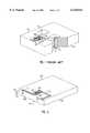
- FIG. 2is an isometric view of a slider in which in the present invention is embodied
- FIG. 3is an isometric view of the slider of FIG. 2 showing a configured air bearing surface
- FIG. 4is a view of the trailing end of the slider shown in FIG. 2.
- FIG. 1illustrates a prior art air bearing slider 100 formed from a nonmagnetic ceramic substrate having a leading end 118 and a trailing end 119.
- the sliderhas an air bearing surface (ABS) extending between said ends (not shown in FIG. 1) that flies closely adjacent to the surface of a magnetic recording disk.
- a thin film magnetic transduceris formed on a surface of the slider.
- the transducercomprises a first pole layer P1, a second pole layer P2, and a transducing gap between the P1 and P2 pole layers.
- Conductive coils 102, 103are disposed between and electrically insulated from the P1 and P2 pole layers.
- the pole layersform a magnetic yoke 105 around the insulated coils.
- the ends 104, 106 of the coil 102 and 103respectively are connected to interconnect traces 108, 110 that provide a route in the plane of the coil to a point of contact with vertical metal vias 112, 114.
- the viasprovide a vertical electrical path to the top surface 116 (which is opposite to the air bearing surface) of the slider.
- Metalis deposited on the surface 116 to provide a bond pad 120 that is electrically connected to the via 114, shown in the cutaway shaded portion of FIG. 1.
- metalis deposited on the surface 116 to provide a bond pad (not shown) that is electrically connected to the via 112.
- a wire harness(not shown) is soldered to the bond pads thereby connecting external read write circuitry to the coil.
- the disadvantage of this type of connectionis that it is complex to manufacture, the vias tend to protrude, and the bond pads on the surface 116 of the slider are subject to breakage.
- an air bearing slider 200 of an inductive magnetic headconstructed in accordance with this invention, has an air bearing surface 202 that is shown in FIG. 3.
- the slideris shown top side down, the top surface 204 being opposite to the ABS.
- the sliderhas a trailing end 206 joining the ABS and the opposite surface 204.
- First and second spaced magnetic pole layersdefine a magnetic yoke region 205.
- Coil structure 201, 203is disposed in a plane between the pole layers and insulated therefrom.
- First and second copper traces 212, 214are deposited to provide a route from the coil structure to the trailing end 206 of the slider.
- First and second gold foil bond pads 216, 218,are attached to the ends 220, 222 of the copper traces, with silver epoxy for example.
- the ABS 202may be formed on a diamond-like carbon (DLC) layer that is deposited above the transducer and interconnect traces and configured with etched rails 224.
- DLCdiamond-like carbon
- the sliderwith gold pads 216, 218 attached, is shown in FIG. 3.
- the electrical connection between the transducer and the read/write driver electronicsmay be made by twisted wires which run the length of the suspension load beam and extend over the flexure and slider. In this case, the ends of the wires can be soldered or ultrasonically bonded to the gold pads 216 and 218 on the slider.
- a flexure with embedded wires and bonding padscan be used.
- the conductive tracesterminate in conductive pads at a forward section of the flexure for connection to the corresponding gold pads 216 and 218 on the slider.
- the connectionscan be made by known techniques such as stitch bonding or ultrasonic welding.
- FIG. 4is a view of the trailing end 206 of the slider shown in FIG. 2.
- the coil structure 201, 203,copper traces 212, 214, and the ends thereof, 220, 222,are shown by broken lines as the structure is embedded in the slider 200.
- the bond pads 216, 218,measure about 0.004 inch ⁇ 0.006 inch and are spaced 0.002 inch from the sides of the slider and 0.0015 inch from the ABS surface 202.
- the slider heightis about 0.012 inch.
- any known method of forming a coil structure in a magnetic transducermay be used to form the coil structure described herein.
- a method of manufacturing a thin film magnetic transducer in which a layer of photoresist material is used to pattern the turns of a bi-level electrical coilis described in U.S. Pat. No. 5,472,736 "Method of making a bi-level coil for a thin film magnetic transducer" issued Dec. 5, 1995 to Barr et al.
- U.S. Pat. No. 5,173,826Thin film head with coils of varying thickness
- a thin film head assemblyincludes a coil structure having a thin coil layer that extends within and beyond the magnetic yoke area delineated between opposing magnetic pole layers, and an additional coil layer formed as a step segment adjacent to the thin layer.
- the additional layeris spaced away from the pole layers and the magnetic yoke area and provides a thickened coil area which affords a significant reduction in coil resistance.
- a suitable substrateis first prepared. Then, a first magnetic pole layer defining a first pole of magnetic yoke region 205 is deposited on the substrate in a first plane of the transducer. Next a conductive material is plated in a pattern to form coil structure 201, 203 disposed in a second plane above the first plane.
- the coil structurehas first and second traces 212, 214, extending in the second plane to a trailing end 206 of the substrate.
- the first and second traces of the coil structureare substantially planar and extend beyond the magnetic yoke region 205 to the trailing end 206 of the substrate.
- the first and second tracesprovide, respectively, first and second exposed ends 220, 222, of the coil at the trailing end 206.
- a second magnetic pole layeris deposited over a suitable insulating layer defining a second pole of the magnetic yoke region 205 in a third plane above the coil structure.
- First and second bonding pads 216, 218, made of gold foil, for example,are attached, respectively, to the first and second exposed ends 220, 222 of the coil traces 212, 214 at the trailing end 206 with a metal adhesive, such as silver epoxy.
- Rails 224are configured by etching a DLC layer 230 of about 120 microinches up to 100 microinches above the transducer and interconnect traces.
Landscapes
- Magnetic Heads (AREA)
- Adjustment Of The Magnetic Head Position Track Following On Tapes (AREA)
Abstract
Description
Claims (10)
Priority Applications (1)
| Application Number | Priority Date | Filing Date | Title |
|---|---|---|---|
| US09/105,598US6125014A (en) | 1998-06-26 | 1998-06-26 | Via-less connection using interconnect traces between bond pads and a transducer coil of a magnetic head slider |
Applications Claiming Priority (1)
| Application Number | Priority Date | Filing Date | Title |
|---|---|---|---|
| US09/105,598US6125014A (en) | 1998-06-26 | 1998-06-26 | Via-less connection using interconnect traces between bond pads and a transducer coil of a magnetic head slider |
Publications (1)
| Publication Number | Publication Date |
|---|---|
| US6125014Atrue US6125014A (en) | 2000-09-26 |
Family
ID=22306738
Family Applications (1)
| Application Number | Title | Priority Date | Filing Date |
|---|---|---|---|
| US09/105,598Expired - Fee RelatedUS6125014A (en) | 1998-06-26 | 1998-06-26 | Via-less connection using interconnect traces between bond pads and a transducer coil of a magnetic head slider |
Country Status (1)
| Country | Link |
|---|---|
| US (1) | US6125014A (en) |
Cited By (44)
| Publication number | Priority date | Publication date | Assignee | Title |
|---|---|---|---|---|
| US6542339B1 (en)* | 1997-01-25 | 2003-04-01 | Tdk Corporation | Inverted hybrid thin film magnetic head and method of manufacturing the same |
| US20030142444A1 (en)* | 2002-01-26 | 2003-07-31 | Bin Hua Tan | Method and apparatus for the prevention of electrostatic discharge (ESD) by a hard drive magnetic head involving the utilization of anisotropic conductive paste (ACP) in the securement to a head-gimbal assembly (HGA) |
| US20060044689A1 (en)* | 2004-08-26 | 2006-03-02 | Lille Jeffrey S | Slider with bonding pads opposite the air bearing surface and method for producing the same |
| US7116523B2 (en)* | 1998-12-21 | 2006-10-03 | Hitachi Global Storage Technologies Netherlands B.V. | Interconnect module for use in a suspension assembly |
| US20090168247A1 (en)* | 2007-12-28 | 2009-07-02 | Christian Rene Bonhote | Magnetic head with embedded solder connection and method for manufacture thereof |
| US7593190B1 (en) | 2001-12-21 | 2009-09-22 | Western Digital (Fremont), Llc | Flexure design and assembly process for attachment of slider using solder and laser reflow |
| US7729089B1 (en) | 2006-10-13 | 2010-06-01 | Western Digital Technologies, Inc. | Head-gimbal assembly including a flexure tongue with stand-offs arranged to facilitate lateral light entry |
| US7995310B1 (en) | 2006-11-09 | 2011-08-09 | Western Digital Technologies, Inc. | Head-gimbal assembly including a flexure tongue with adhesive receptacles disposed adjacent to stand-offs |
| US8164858B1 (en) | 2009-11-04 | 2012-04-24 | Western Digital (Fremont), Llc | Read head having conductive filler in insulated hole through substrate |
| US8218268B1 (en) | 2009-05-27 | 2012-07-10 | Western Digital Technologies, Inc. | Head gimbal assembly having a load beam aperature over conductive heating pads that are offset from head bonding pads |
| US8929180B1 (en) | 2013-04-25 | 2015-01-06 | Western Digital Technologies, Inc. | Energy-assisted magnetic recording device having laser driving signal and magnetic write signal sharing same electrical conductor |
| US8934199B1 (en) | 2014-03-31 | 2015-01-13 | Western Digital Technologies, Inc. | Disk drive head suspension tail with bond pad edge alignment features |
| US8976491B1 (en) | 2013-05-09 | 2015-03-10 | Western Digital Technologies, Inc. | Disk drive head suspension distal non-op shock limiter with branched arms |
| US8988830B1 (en) | 2013-05-13 | 2015-03-24 | Western Digital (Fremont), Llc | Air bearing design to mitigate lube waterfall effect |
| US9042048B1 (en) | 2014-09-30 | 2015-05-26 | Western Digital (Fremont), Llc | Laser-ignited reactive HAMR bonding |
| US9064513B1 (en) | 2014-03-07 | 2015-06-23 | Western Digital Technologies, Inc. | Disk drive suspension assembly with flexure having dual conductive layers with staggered traces |
| US9070387B1 (en) | 2013-08-23 | 2015-06-30 | Western Digital Technologies, Inc. | Integrated heat-assisted magnetic recording head/laser assembly |
| US9093102B1 (en) | 2013-03-12 | 2015-07-28 | Western Digital Technologies, Inc. | Systems and methods for tuning seed layer hardness in components of magnetic recording systems |
| US9099145B1 (en) | 2013-12-24 | 2015-08-04 | Western Digital (Fremont), Llc | High contrast alignment marker |
| US9105282B1 (en) | 2013-05-20 | 2015-08-11 | Western Digital Technologies, Inc. | Head gimbal assembly carrier with adjustable protective bar |
| US9135935B1 (en) | 2013-10-11 | 2015-09-15 | Western Digital Technologies, Inc. | Customized head gimbal assembly bonding skew angle for adjusting two-dimensional magnetic recording reader alignment |
| US9165579B1 (en) | 2014-09-26 | 2015-10-20 | Western Digital (Fremont), Llc | Air bearing area configuration for reducing flying height hump across a stroke |
| US9171562B1 (en) | 2015-03-19 | 2015-10-27 | Western Digital (Fremont), Llc | Patterned metal layer to control solder connection between laser and submount in a magnetic head |
| US9183859B1 (en) | 2014-11-11 | 2015-11-10 | Western Digital (Fremont), Llc | HAMR writer pole length characterization |
| US9190089B1 (en) | 2014-12-24 | 2015-11-17 | Western Digital (Fremont), Llc | Air bearing area configuration for contaminating particle removal |
| US9190090B1 (en) | 2014-12-24 | 2015-11-17 | Western Digital (Fremont), Llc | Multi step lube blocking air bearing area configuration |
| US9202478B1 (en) | 2015-02-10 | 2015-12-01 | Western Digital (Fremont), Llc | Method and structure for soldering a laser submount to a mounting face of a slider |
| US9230580B1 (en) | 2010-06-30 | 2016-01-05 | Western Digital Technologies, Inc. | Suspension assembly having a microactuator grounded to a flexure |
| US9242340B1 (en) | 2013-03-12 | 2016-01-26 | Western Digital Technologies, Inc. | Method to stress relieve a magnetic recording head transducer utilizing ultrasonic cavitation |
| US9257138B1 (en) | 2014-10-28 | 2016-02-09 | Western Digital (Fremont), Llc | Slider assembly and method of manufacturing same |
| US9293157B1 (en) | 2012-06-28 | 2016-03-22 | Western Digital Technologies, Inc. | Automated active feedback slice and view milling of magnetic head cross-sections |
| US9315008B1 (en) | 2013-07-16 | 2016-04-19 | Western Digital Technologies, Inc. | Method and apparatus for aligning an illumination unit to a slider for a magnetic recording device |
| US9343084B2 (en) | 2012-03-14 | 2016-05-17 | Western Digital Technologies, Inc. | Systems and methods for correcting slider parallelism error using compensation lapping |
| US9361916B1 (en) | 2014-03-13 | 2016-06-07 | Western Digital (Fremont) | Electrical lapping guide for dimensional control of back side of heat assisted magnetic recording device |
| US9368139B1 (en) | 2015-03-20 | 2016-06-14 | Western Digital (Fremont), Llc | Slider back side etching to increase shear strength between suspension and slider |
| US9372078B1 (en) | 2014-06-20 | 2016-06-21 | Western Digital (Fremont), Llc | Detecting thickness variation and quantitative depth utilizing scanning electron microscopy with a surface profiler |
| US9387568B1 (en) | 2013-02-27 | 2016-07-12 | Western Digital Technologies, Inc. | Systems and methods for correcting fabrication error in magnetic recording heads using magnetic write width measurements |
| US9431044B1 (en) | 2014-05-07 | 2016-08-30 | Western Digital (Fremont), Llc | Slider having shock and particle resistance |
| US9431037B2 (en) | 2013-03-12 | 2016-08-30 | Western Digitatl (Fremont), LLC | Systems and methods for monitoring the power of a light source utilized in energy-assisted magnetic recording |
| US9659587B1 (en) | 2015-11-06 | 2017-05-23 | Western Digital (Fremont), Llc | Magnetic head having a reader overcoat with DLC and a recessed writer overcoat without DLC |
| US9659589B2 (en) | 2015-09-29 | 2017-05-23 | Western Digital (Fremont), Llc | Free-standing reflector usable in heat assisted magnetic recording technology |
| US9685187B1 (en) | 2014-09-26 | 2017-06-20 | Western Digital (Fremont), Llc | Bonding tool and method for high accuracy chip-to-chip bonding |
| US9805748B1 (en) | 2014-06-24 | 2017-10-31 | Western Digital (Fremont), Llc | System and method for providing a protective layer having a graded intermediate layer |
| US9870788B2 (en) | 2014-01-08 | 2018-01-16 | Western Digital (Fremont), Llc | Method of adjusting tilt using magnetic erase width feedback |
Citations (7)
| Publication number | Priority date | Publication date | Assignee | Title |
|---|---|---|---|---|
| US5590005A (en)* | 1992-12-10 | 1996-12-31 | Nec Corporation | Thin film magnetic head |
| US5721651A (en)* | 1995-08-02 | 1998-02-24 | Tdk Corporation | Thin film magnetic head and manufacturing method of the same |
| US5781377A (en)* | 1996-02-20 | 1998-07-14 | Seagate Technology, Inc. | Slider with protective DLC or nonhygroscopic coating on the trailing edge face |
| US5786962A (en)* | 1996-01-24 | 1998-07-28 | Sony Corporation | Magnetic head assembly |
| US5796549A (en)* | 1996-07-03 | 1998-08-18 | Seagate Technology, Inc. | Universal bond pad configuration |
| US5894380A (en)* | 1995-12-15 | 1999-04-13 | Hitachi, Ltd. | Recording/reproducing separation type magnetic head |
| US5896248A (en)* | 1997-09-05 | 1999-04-20 | Read-Rite Corporation | Bond pads for metal welding of flexure to air bearing slider and grounding configuration thereof |
- 1998
- 1998-06-26USUS09/105,598patent/US6125014A/ennot_activeExpired - Fee Related
Patent Citations (7)
| Publication number | Priority date | Publication date | Assignee | Title |
|---|---|---|---|---|
| US5590005A (en)* | 1992-12-10 | 1996-12-31 | Nec Corporation | Thin film magnetic head |
| US5721651A (en)* | 1995-08-02 | 1998-02-24 | Tdk Corporation | Thin film magnetic head and manufacturing method of the same |
| US5894380A (en)* | 1995-12-15 | 1999-04-13 | Hitachi, Ltd. | Recording/reproducing separation type magnetic head |
| US5786962A (en)* | 1996-01-24 | 1998-07-28 | Sony Corporation | Magnetic head assembly |
| US5781377A (en)* | 1996-02-20 | 1998-07-14 | Seagate Technology, Inc. | Slider with protective DLC or nonhygroscopic coating on the trailing edge face |
| US5796549A (en)* | 1996-07-03 | 1998-08-18 | Seagate Technology, Inc. | Universal bond pad configuration |
| US5896248A (en)* | 1997-09-05 | 1999-04-20 | Read-Rite Corporation | Bond pads for metal welding of flexure to air bearing slider and grounding configuration thereof |
Cited By (49)
| Publication number | Priority date | Publication date | Assignee | Title |
|---|---|---|---|---|
| US6542339B1 (en)* | 1997-01-25 | 2003-04-01 | Tdk Corporation | Inverted hybrid thin film magnetic head and method of manufacturing the same |
| US7116523B2 (en)* | 1998-12-21 | 2006-10-03 | Hitachi Global Storage Technologies Netherlands B.V. | Interconnect module for use in a suspension assembly |
| US7593190B1 (en) | 2001-12-21 | 2009-09-22 | Western Digital (Fremont), Llc | Flexure design and assembly process for attachment of slider using solder and laser reflow |
| US8159790B2 (en) | 2002-01-26 | 2012-04-17 | Sae Magnetics (H.K.) Ltd. | Method and apparatus for the prevention of electrostatic discharge (ESD) by a hard drive magnetic head involving the utilization of anisotropic conductive paste (ACP) in the securement to a head-gimbal assembly (HGA) |
| US20030142444A1 (en)* | 2002-01-26 | 2003-07-31 | Bin Hua Tan | Method and apparatus for the prevention of electrostatic discharge (ESD) by a hard drive magnetic head involving the utilization of anisotropic conductive paste (ACP) in the securement to a head-gimbal assembly (HGA) |
| US20060044689A1 (en)* | 2004-08-26 | 2006-03-02 | Lille Jeffrey S | Slider with bonding pads opposite the air bearing surface and method for producing the same |
| US7535676B2 (en)* | 2004-08-26 | 2009-05-19 | Hitachi Global Storage Technologies B.V. | Slider with bonding pads opposite the air bearing surface |
| US7729089B1 (en) | 2006-10-13 | 2010-06-01 | Western Digital Technologies, Inc. | Head-gimbal assembly including a flexure tongue with stand-offs arranged to facilitate lateral light entry |
| US7995310B1 (en) | 2006-11-09 | 2011-08-09 | Western Digital Technologies, Inc. | Head-gimbal assembly including a flexure tongue with adhesive receptacles disposed adjacent to stand-offs |
| US20090168247A1 (en)* | 2007-12-28 | 2009-07-02 | Christian Rene Bonhote | Magnetic head with embedded solder connection and method for manufacture thereof |
| US8218268B1 (en) | 2009-05-27 | 2012-07-10 | Western Digital Technologies, Inc. | Head gimbal assembly having a load beam aperature over conductive heating pads that are offset from head bonding pads |
| US8325447B1 (en) | 2009-05-27 | 2012-12-04 | Western Digital Technologies, Inc. | Head gimbal assembly having a load beam aperature over conductive heating pads that are offset from head bonding pads |
| US8164858B1 (en) | 2009-11-04 | 2012-04-24 | Western Digital (Fremont), Llc | Read head having conductive filler in insulated hole through substrate |
| US8756795B1 (en) | 2009-11-04 | 2014-06-24 | Western Digital (Fremont), Llc | Method for manufacturing a read head having conductive filler in insulated hole through substrate |
| US9230580B1 (en) | 2010-06-30 | 2016-01-05 | Western Digital Technologies, Inc. | Suspension assembly having a microactuator grounded to a flexure |
| US9343084B2 (en) | 2012-03-14 | 2016-05-17 | Western Digital Technologies, Inc. | Systems and methods for correcting slider parallelism error using compensation lapping |
| US9293157B1 (en) | 2012-06-28 | 2016-03-22 | Western Digital Technologies, Inc. | Automated active feedback slice and view milling of magnetic head cross-sections |
| US9387568B1 (en) | 2013-02-27 | 2016-07-12 | Western Digital Technologies, Inc. | Systems and methods for correcting fabrication error in magnetic recording heads using magnetic write width measurements |
| US9242340B1 (en) | 2013-03-12 | 2016-01-26 | Western Digital Technologies, Inc. | Method to stress relieve a magnetic recording head transducer utilizing ultrasonic cavitation |
| US9449631B2 (en) | 2013-03-12 | 2016-09-20 | Western Digital Technologies, Inc. | Slider for magnetic recording system |
| US9431037B2 (en) | 2013-03-12 | 2016-08-30 | Western Digitatl (Fremont), LLC | Systems and methods for monitoring the power of a light source utilized in energy-assisted magnetic recording |
| US9093102B1 (en) | 2013-03-12 | 2015-07-28 | Western Digital Technologies, Inc. | Systems and methods for tuning seed layer hardness in components of magnetic recording systems |
| US8929180B1 (en) | 2013-04-25 | 2015-01-06 | Western Digital Technologies, Inc. | Energy-assisted magnetic recording device having laser driving signal and magnetic write signal sharing same electrical conductor |
| US8976491B1 (en) | 2013-05-09 | 2015-03-10 | Western Digital Technologies, Inc. | Disk drive head suspension distal non-op shock limiter with branched arms |
| US8988830B1 (en) | 2013-05-13 | 2015-03-24 | Western Digital (Fremont), Llc | Air bearing design to mitigate lube waterfall effect |
| US9105282B1 (en) | 2013-05-20 | 2015-08-11 | Western Digital Technologies, Inc. | Head gimbal assembly carrier with adjustable protective bar |
| US9315008B1 (en) | 2013-07-16 | 2016-04-19 | Western Digital Technologies, Inc. | Method and apparatus for aligning an illumination unit to a slider for a magnetic recording device |
| US9070387B1 (en) | 2013-08-23 | 2015-06-30 | Western Digital Technologies, Inc. | Integrated heat-assisted magnetic recording head/laser assembly |
| US9135935B1 (en) | 2013-10-11 | 2015-09-15 | Western Digital Technologies, Inc. | Customized head gimbal assembly bonding skew angle for adjusting two-dimensional magnetic recording reader alignment |
| US9099145B1 (en) | 2013-12-24 | 2015-08-04 | Western Digital (Fremont), Llc | High contrast alignment marker |
| US9870788B2 (en) | 2014-01-08 | 2018-01-16 | Western Digital (Fremont), Llc | Method of adjusting tilt using magnetic erase width feedback |
| US9064513B1 (en) | 2014-03-07 | 2015-06-23 | Western Digital Technologies, Inc. | Disk drive suspension assembly with flexure having dual conductive layers with staggered traces |
| US9361916B1 (en) | 2014-03-13 | 2016-06-07 | Western Digital (Fremont) | Electrical lapping guide for dimensional control of back side of heat assisted magnetic recording device |
| US8934199B1 (en) | 2014-03-31 | 2015-01-13 | Western Digital Technologies, Inc. | Disk drive head suspension tail with bond pad edge alignment features |
| US9431044B1 (en) | 2014-05-07 | 2016-08-30 | Western Digital (Fremont), Llc | Slider having shock and particle resistance |
| US9372078B1 (en) | 2014-06-20 | 2016-06-21 | Western Digital (Fremont), Llc | Detecting thickness variation and quantitative depth utilizing scanning electron microscopy with a surface profiler |
| US9805748B1 (en) | 2014-06-24 | 2017-10-31 | Western Digital (Fremont), Llc | System and method for providing a protective layer having a graded intermediate layer |
| US9685187B1 (en) | 2014-09-26 | 2017-06-20 | Western Digital (Fremont), Llc | Bonding tool and method for high accuracy chip-to-chip bonding |
| US9165579B1 (en) | 2014-09-26 | 2015-10-20 | Western Digital (Fremont), Llc | Air bearing area configuration for reducing flying height hump across a stroke |
| US9042048B1 (en) | 2014-09-30 | 2015-05-26 | Western Digital (Fremont), Llc | Laser-ignited reactive HAMR bonding |
| US9257138B1 (en) | 2014-10-28 | 2016-02-09 | Western Digital (Fremont), Llc | Slider assembly and method of manufacturing same |
| US9183859B1 (en) | 2014-11-11 | 2015-11-10 | Western Digital (Fremont), Llc | HAMR writer pole length characterization |
| US9190090B1 (en) | 2014-12-24 | 2015-11-17 | Western Digital (Fremont), Llc | Multi step lube blocking air bearing area configuration |
| US9190089B1 (en) | 2014-12-24 | 2015-11-17 | Western Digital (Fremont), Llc | Air bearing area configuration for contaminating particle removal |
| US9202478B1 (en) | 2015-02-10 | 2015-12-01 | Western Digital (Fremont), Llc | Method and structure for soldering a laser submount to a mounting face of a slider |
| US9171562B1 (en) | 2015-03-19 | 2015-10-27 | Western Digital (Fremont), Llc | Patterned metal layer to control solder connection between laser and submount in a magnetic head |
| US9368139B1 (en) | 2015-03-20 | 2016-06-14 | Western Digital (Fremont), Llc | Slider back side etching to increase shear strength between suspension and slider |
| US9659589B2 (en) | 2015-09-29 | 2017-05-23 | Western Digital (Fremont), Llc | Free-standing reflector usable in heat assisted magnetic recording technology |
| US9659587B1 (en) | 2015-11-06 | 2017-05-23 | Western Digital (Fremont), Llc | Magnetic head having a reader overcoat with DLC and a recessed writer overcoat without DLC |
Similar Documents
| Publication | Publication Date | Title |
|---|---|---|
| US6125014A (en) | Via-less connection using interconnect traces between bond pads and a transducer coil of a magnetic head slider | |
| US8045295B2 (en) | Method and apparatus for providing an additional ground pad and electrical connection for grounding a magnetic recording head | |
| US6275358B1 (en) | Conductor trace array having passive stub conductors | |
| US4616279A (en) | Electrical connections for thin film transducer heads | |
| US8792213B1 (en) | Tethered gimbal on suspension for improved flyability | |
| JP2713762B2 (en) | Head support device | |
| US6229673B1 (en) | Magnetic head assembly with contact-type head chip mounting and electrically connecting arrangements | |
| US6587310B1 (en) | Magnetic head suspension with single layer preshaped trace interconnect | |
| US6833978B2 (en) | Micro-actuator integrated lead suspension head terminations | |
| US7059868B1 (en) | Connection of trace circuitry in a computer disk drive system | |
| KR100336739B1 (en) | Converter Suspension System | |
| JP2006503402A5 (en) | ||
| JP2001118216A (en) | Magnetic writing head having divided coil structure, thin-film magnetic writing head and its manufacturing method | |
| JPH103633A (en) | Spacer device for slider/suspension and space control method | |
| JP2001501762A (en) | Flex circuit flexure with integrated high compliance gimbal | |
| US4796132A (en) | Thin film magnetic head having Au ultrasonic connection structure | |
| JP3342638B2 (en) | Head gimbal assembly and information storage system | |
| CN108962287A (en) | The circuit block of disk drive suspension | |
| JP2005502195A (en) | Wireless suspension for multi-drive | |
| WO2000030081A1 (en) | Record/reproduce head support mechanism and record/reproduce apparatus | |
| US5771138A (en) | Head gimbal assembly with transducer wires attached at two points to slider | |
| JP3196954B2 (en) | Magnetic head device | |
| JP3731731B2 (en) | Manufacturing method of magnetic head device | |
| JP3241448B2 (en) | Magnetic head device | |
| JPH06187612A (en) | Magnetic head assembly |
Legal Events
| Date | Code | Title | Description |
|---|---|---|---|
| AS | Assignment | Owner name:READ-RITE CORPORATION, CALIFORNIA Free format text:ASSIGNMENT OF ASSIGNORS INTEREST;ASSIGNOR:RIEDLIN, VERNON M. JR.;REEL/FRAME:009295/0286 Effective date:19980617 | |
| AS | Assignment | Owner name:CANADIAN IMPERIAL BANK OF COMMERCE NEW YORK AGENCY Free format text:SECURITY AGREEMENT;ASSIGNOR:READ-RITE CORPORATION, A DELAWARE CORPORATION;REEL/FRAME:009529/0876 Effective date:19980814 | |
| AS | Assignment | Owner name:READ-RITE CORPORATION, CALIFORNIA Free format text:ASSIGNMENT AND RELEASE OF INTELLECTUAL PROPERTY SECURITY AGREEMENT;ASSIGNOR:CANADIAN IMPERIAL BANK OF COMMERCE, NEW YORK AGENCY, AS AGENT;REEL/FRAME:011680/0538 Effective date:20010326 | |
| AS | Assignment | Owner name:TENNENBAUM CAPITAL PARTNERS, LLC, CALIFORNIA Free format text:SECURITY INTEREST;ASSIGNOR:READ-RITE CORPORATION;REEL/FRAME:013616/0399 Effective date:20021224 | |
| AS | Assignment | Owner name:WESTERN DIGITAL (FREMONT), INC., CALIFORNIA Free format text:ASSIGNMENT OF ASSIGNORS INTEREST;ASSIGNOR:READ-RITE CORPORATION;REEL/FRAME:014506/0765 Effective date:20030731 | |
| AS | Assignment | Owner name:READ-RITE CORPORATION, CALIFORNIA Free format text:RELEASE OF SECURITY INTEREST;ASSIGNOR:TENNENBAUM CAPITAL PARTNERS, LLC;REEL/FRAME:014499/0476 Effective date:20030731 | |
| FPAY | Fee payment | Year of fee payment:4 | |
| AS | Assignment | Owner name:GENERAL ELECTRIC CAPITAL CORPORATION, AS AGENT, CA Free format text:SECURITY INTEREST;ASSIGNORS:WESTERN DIGITAL TECHNOLOGIES, INC.;WESTERN DIGITAL (FREMONT), INC.;REEL/FRAME:014830/0957 Effective date:20030919 | |
| FPAY | Fee payment | Year of fee payment:8 | |
| AS | Assignment | Owner name:WESTERN DIGITAL TECHNOLOGIES, INC., CALIFORNIA Free format text:RELEASE BY SECURED PARTY;ASSIGNOR:GENERAL ELECTRIC CAPITAL CORPORATION, AS AGENT;REEL/FRAME:020599/0489 Effective date:20070809 Owner name:WESTERN DIGITAL (FREMONT), INC., CALIFORNIA Free format text:RELEASE BY SECURED PARTY;ASSIGNOR:GENERAL ELECTRIC CAPITAL CORPORATION, AS AGENT;REEL/FRAME:020599/0489 Effective date:20070809 | |
| REMI | Maintenance fee reminder mailed | ||
| LAPS | Lapse for failure to pay maintenance fees | ||
| STCH | Information on status: patent discontinuation | Free format text:PATENT EXPIRED DUE TO NONPAYMENT OF MAINTENANCE FEES UNDER 37 CFR 1.362 | |
| FP | Lapsed due to failure to pay maintenance fee | Effective date:20120926 | |
| AS | Assignment | Owner name:WESTERN DIGITAL TECHNOLOGIES, INC., CALIFORNIA Free format text:ASSIGNMENT OF ASSIGNORS INTEREST;ASSIGNOR:WESTERN DIGITAL (FREMONT), LLC;REEL/FRAME:050450/0582 Effective date:20190508 |