US6123985A - Method of fabricating a membrane-actuated charge controlled mirror (CCM) - Google Patents
Method of fabricating a membrane-actuated charge controlled mirror (CCM)Download PDFInfo
- Publication number
- US6123985A US6123985AUS09/179,860US17986098AUS6123985AUS 6123985 AUS6123985 AUS 6123985AUS 17986098 AUS17986098 AUS 17986098AUS 6123985 AUS6123985 AUS 6123985A
- Authority
- US
- United States
- Prior art keywords
- membrane
- mirror
- array
- glass panel
- micromirrors
- Prior art date
- Legal status (The legal status is an assumption and is not a legal conclusion. Google has not performed a legal analysis and makes no representation as to the accuracy of the status listed.)
- Expired - Lifetime
Links
- 238000004519manufacturing processMethods0.000titleclaimsabstractdescription33
- 239000012528membraneSubstances0.000claimsabstractdescription75
- 239000011521glassSubstances0.000claimsabstractdescription35
- 238000000034methodMethods0.000claimsabstractdescription32
- 229920000642polymerPolymers0.000claimsabstractdescription15
- 229910052751metalInorganic materials0.000claimsdescription19
- 239000002184metalSubstances0.000claimsdescription19
- 239000004020conductorSubstances0.000claimsdescription8
- 239000002861polymer materialSubstances0.000claimsdescription5
- 238000000059patterningMethods0.000claims11
- 239000011810insulating materialSubstances0.000claims2
- 238000012545processingMethods0.000abstractdescription10
- 230000000873masking effectEffects0.000abstractdescription4
- 201000000760cerebral cavernous malformationDiseases0.000abstract2
- 239000000758substrateSubstances0.000description21
- 238000010894electron beam technologyMethods0.000description9
- 229910052782aluminiumInorganic materials0.000description5
- XAGFODPZIPBFFR-UHFFFAOYSA-NaluminiumChemical compound[Al]XAGFODPZIPBFFR-UHFFFAOYSA-N0.000description5
- 239000000463materialSubstances0.000description5
- 238000001020plasma etchingMethods0.000description5
- VYPSYNLAJGMNEJ-UHFFFAOYSA-NSilicium dioxideChemical compoundO=[Si]=OVYPSYNLAJGMNEJ-UHFFFAOYSA-N0.000description4
- 239000010408filmSubstances0.000description4
- 239000004952PolyamideSubstances0.000description3
- 238000003491arrayMethods0.000description3
- 229920003229poly(methyl methacrylate)Polymers0.000description3
- 229920002647polyamidePolymers0.000description3
- 239000004926polymethyl methacrylateSubstances0.000description3
- 235000012431wafersNutrition0.000description3
- XUIMIQQOPSSXEZ-UHFFFAOYSA-NSiliconChemical compound[Si]XUIMIQQOPSSXEZ-UHFFFAOYSA-N0.000description2
- 238000000151depositionMethods0.000description2
- 239000003989dielectric materialSubstances0.000description2
- 239000011159matrix materialSubstances0.000description2
- 230000003287optical effectEffects0.000description2
- 238000002161passivationMethods0.000description2
- 238000000623plasma-assisted chemical vapour depositionMethods0.000description2
- 238000002310reflectometryMethods0.000description2
- 229910052594sapphireInorganic materials0.000description2
- 239000010980sapphireSubstances0.000description2
- 238000007789sealingMethods0.000description2
- 229910052710siliconInorganic materials0.000description2
- 239000010703siliconSubstances0.000description2
- 239000000377silicon dioxideSubstances0.000description2
- 230000003068static effectEffects0.000description2
- 238000012546transferMethods0.000description2
- 101100269850Caenorhabditis elegans mask-1 geneProteins0.000description1
- 238000005411Van der Waals forceMethods0.000description1
- 238000004380ashingMethods0.000description1
- 238000000576coating methodMethods0.000description1
- 229910052681coesiteInorganic materials0.000description1
- 229910052906cristobaliteInorganic materials0.000description1
- 230000008021depositionEffects0.000description1
- 238000013461designMethods0.000description1
- 238000011161developmentMethods0.000description1
- 238000005530etchingMethods0.000description1
- 230000003993interactionEffects0.000description1
- 238000005304joiningMethods0.000description1
- 229910001338liquidmetalInorganic materials0.000description1
- 238000001459lithographyMethods0.000description1
- 230000000149penetrating effectEffects0.000description1
- 238000000206photolithographyMethods0.000description1
- 239000011148porous materialSubstances0.000description1
- 239000011435rockSubstances0.000description1
- 239000004065semiconductorSubstances0.000description1
- 235000012239silicon dioxideNutrition0.000description1
- 125000006850spacer groupChemical group0.000description1
- 238000004544sputter depositionMethods0.000description1
- 229910052682stishoviteInorganic materials0.000description1
- 239000010409thin filmSubstances0.000description1
- 238000000427thin-film depositionMethods0.000description1
- 229910052905tridymiteInorganic materials0.000description1
Images


Classifications
- G—PHYSICS
- G02—OPTICS
- G02B—OPTICAL ELEMENTS, SYSTEMS OR APPARATUS
- G02B26/00—Optical devices or arrangements for the control of light using movable or deformable optical elements
- G02B26/08—Optical devices or arrangements for the control of light using movable or deformable optical elements for controlling the direction of light
- G02B26/0816—Optical devices or arrangements for the control of light using movable or deformable optical elements for controlling the direction of light by means of one or more reflecting elements
- G02B26/0833—Optical devices or arrangements for the control of light using movable or deformable optical elements for controlling the direction of light by means of one or more reflecting elements the reflecting element being a micromechanical device, e.g. a MEMS mirror, DMD
- G02B26/0841—Optical devices or arrangements for the control of light using movable or deformable optical elements for controlling the direction of light by means of one or more reflecting elements the reflecting element being a micromechanical device, e.g. a MEMS mirror, DMD the reflecting element being moved or deformed by electrostatic means
Definitions
- This inventionrelates to electrostatically-actuated light modulators and more specifically to a method of fabricating a micromirror faceplate using a combination of flat-panel manufacturing and MicroElectroMechanical Systems (MEMS) fabrication techniques.
- MEMSMicroElectroMechanical Systems
- a beam of lightis directed towards a light valve target that, in response to a video addressing signal, imparts a modulation onto the beam in proportion to the amplitude of the deflection of the individual reflective elements, e.g. a reflective thin-film or an array of micromirrors.
- the amplitude or phase modulated beamis then passed through projection optics to form the image.
- the targetproduces attractive electrostatic forces between the underlying substrate and the individual reflective elements that pull them inward toward the substrate.
- the amplitude of deflectioncorresponds to the pixel intensity in the video signal. It is well known that optical performance of the light modulator is closely tied to deflection range, electrostatic instability and resolution.
- RCAdeveloped a new Schlieren light valve that used a high energy scanning electron beam in a vacuum to address a thin metal film that is stretched over a support grid in close proximity to a glass substrate, which is described in J. A. van Raalte, "A New Schlieren Light Valve for Television Projection", Applied Optics Vol. 9, No. 10, (Oct. 1970), p. 2225.
- the electron beampenetrates the metal film and deposits charge on the glass substrate in proportion to the intensity of the video signal.
- the deposited chargeproduces an attractive force that deforms the metal film inward towards the substrate, which causes a portion of the reflected light to miss the stop, thereby increasing screen brightness until all the light reaches the screen.
- each pixeldeforms parabolically so that light incident on the central portion of each pixel element is not deflected. This limits fill factor and optical efficiency.
- deflection rangeis limited to about 20% to maintain parabolic deformation.
- CTPcharge transfer plate
- An array of insulating posts formed in or on the CTPsupport a deformable reflecting membrane that spans the wells.
- the CTPserves as a high-density multi-feedthrough vacuum-to-air interface that both decouples the electron beam interaction from the membrane and provides the structural support required to hold off atmospheric pressure.
- the vacuum-to-air interfaceallows the reflective membrane to be built and operated in air rather than a vacuum.
- Warde's membrane light modulatoris fabricated by either a) removing material from the CTP's feedthroughs to form an array of recessed wells or b) photolithographically defining insulating spacers on the CTP to define the recessed wells.
- a polymeric membraneis deposited on the CTP over the wells such that a reliable bond between the two dielectric surfaces is established due to Van der Waals forces.
- the fabrication of the CTPis described in detail in U.S. Pat. Nos. 4,794,296 and 4,863,759.
- the high spatial resolution charge transfer feedthrough plate production assemblyconsists essentially of a liquid metal extruder that receives a porous insulative substrate and operates at elevated temperatures to fill each of the pores with a conductive metal. Since the production assembly must assure high resolution parallel conductors that are not shorted together and provide a very high precision vacuum seal between the feedthroughs and the insulating substrate, the process requires specially designed equipment and processing techniques that are far more expensive and less reliable than standard photolithographic techniques.
- the siliconis isotropically wet-etched until the oxide is undercut, leaving four oxide cantilever beams within each pixel supported by a central silicon support post.
- the cloverleaf arrayis then metallized with aluminum for reflectivity.
- the aluminum deposited on the sapphire substrateforms a reference grid electrode near the edges of the mirrors that is held at a d.c. bias.
- a field meshis supported above the mirrors to collect any secondary electrons that are emitted from the mirrors in response to the incident primary electrons.
- the deviceis addressed by a low energy scanning electron beam that deposits a charge pattern on the cloverleaf beams, causing the beams to be deformed toward the reference grid electrode on the substrate by electrostatic actuation.
- Texas Instrumentshas pioneered the development of the digital-mode light modulator with its digital micromirror device (DMD) that uses the pull-in problem to its advantage.
- the DMDemploys a torsional micromirror that is fabricated on a SRAM integrated circuit and rocks back-and-forth between binary positions with the tips of the mirror being pulled down to the base electrodes.
- Time division multiplexingTDM
- the electronics for implementing a TDM addressing schemeare much more complex and expensive than those required for analog modulation.
- Fabrication of the SRAMrequires the normal 14 mask levels on a 4-5" wafer in a CMOS process.
- the fabrication of the 16 ⁇ m ⁇ 16 ⁇ m micromirrors in a large arrayrequires an additional 8 mask levels. The low yield from this complex processing results in a high unit cost. Furthermore, anti-stick coatings complicate the device and increase production costs significantly.
- the present inventionprovides a low cost method of fabricating multiple membrane-actuated charge controlled mirrors (CCMs) on a single glass panel that exhibit increased deflection range, reduced beam current and improved electrostatic stability by combining large area flat panel manufacturing along with traditional MEMS techniques.
- CCMscharge controlled mirrors
- the membrane-actuated CCMincludes a micromirror array that is mounted on a glass substrate and a thin insulating membrane that decouples the micromirror array from the electron beam.
- the membraneis supported by an array of insulating posts and is preferably patterned with an array of attractor pads that improve the field uniformity seen by each of the underlying micromirrors.
- the mirrorsare all connected to a reference potential by an conductive grid on an equipotential layer, which also serves to shield the mirrors from any static or stray charge on the substrate that could otherwise cause instability problems.
- the electron beamwrites a charge pattern onto the attractor pads that causes the micromirrors to deflect toward the membrane.
- the membrane-actuated CCMis fabricated using large area flat panel manufacturing along with traditional MEMS techniques. More specifically, a unique combination of five masking layers is used to fabricate the CCM on a glass panel that is coated with a conductive material. A polymer release layer is patterned on the panel and coated with aluminum that is patterned to define the mirror array. Another thicker polymer release layer is patterned over the mirror array and coated with a low stress dielectric material to define the membrane. A metal layer is then patterned to define the attractor pads.
- the glass panelis diced into individual CCMs. Thereafter, the mirror and post-membrane structures are simultaneously released through vent holes in the membrane to leave the free-standing CCM on a glass substrate.
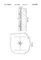
- FIG. 1is a sectional view of a membrane-actuated CCM with a cloverleaf mirror structure and perforated membrane;
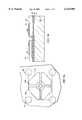
- FIG. 2is view along section 2--2 of FIG. 1 showing a plan view of a cloverleaf mirror configuration
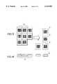
- FIG. 3is a view along section 3--3 of FIG. 1 showing a plane view of a freestanding membrane
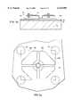
- FIGS. 4a through 4gare sectional views of the fabrication process of the membrane-actuated CCM shown in FIGS. 1-3;
- FIGS. 5a through 5gare plan views of the fabrication process of the membrane-actuated CCM shown in FIGS. 1-3.
- MEMSMicroElectroMechanical Systems
- CCMcharge controlled mirror
- the primary structure built on a glass substrateis a metallic hinged mirror that is decoupled from the electron beam by an insulating membrane. Decoupling also allows the mirror to be designed to optimize reflectivity and exhibit a higher resonant frequency for better video performance.
- the membrane-actuated CCMis preferably fabricated using processing equipment found in active matrix LCD flat panel display manufacturing.
- This equipmentis ideally suited to high volume, low cost manufacturing.
- the technical demands of the micromirror designare such that they do not require leading edge processing equipment.
- Lower cost equipmentthat is one or two generations old relative to the state of the art will meet our technical requirements.
- the process flow for the production of our imagerconsists of two major steps: (1) fabricating the CCM on a glass faceplate and (2) joining and sealing the faceplate to the vacuum cell that houses the electron beam source, e.g. a CRT or flat-panel source such as a field emitter array (FEA).
- a CRT or flat-panel sourcesuch as a field emitter array (FEA).
- the production equipment needed to complete Step 1, fabrication of the micromirror arrayincludes conventional photolithography equipment, conventional thin film deposition equipment and conventional etching equipment.
- the production equipment needed for Step 2while not unusual, is specialized.
- a vacuum assembly and sealing stationmust be designed to bring the three elements (CCM faceplate, seal perform and the vacuum) into the vacuum chamber, align them together with moderate precision and then heat the assembly to form the seal.
- FIGS. 1, 2 and 3A currently preferred embodiment of one pixel of a membrane-actuated CCM faceplate 8 is depicted in FIGS. 1, 2 and 3.
- a thin insulating membrane 10decouples an array of cantilevered micromirrors 12 on a glass substrate 14 from a source of primary electrons.
- Substrate 14is preferably coated with a passivation layer 16 and a thin conducting oxide (TCO) or film (TCF) 18 that holds all of the micromirrors at anode potential and shields them from any static or stray charge that may accumulate on the substrate.
- TCOthin conducting oxide
- TCFfilm
- a conductive gridis preferably patterned on oxide 18 to ensure the electrical continuity of the micromirrors.
- the mirror layeris patterned in a cloverleaf array of four centrally joined cantilever beams 20a, 20b, 20c and 20d that are joined to a common post region 22 by hinges 24a, 24b, 24c and 24d.
- Membrane 10is formed with an integral gull-wing shaped structure in which posts 26 are supported on substrate 14 in the mirrors' common post region 22. Attractor pads 28a-28d on membrane 10 above the corresponding cantilevered beams improve the uniformity of any charge deposited on the membrane. A number of vent holes 30 in membrane 10 that are spaced between cloverleaf arrays are formed during processing to simultaneously release the micromirrors and membrane. This configuration allows the post to be relatively large in diameter with a smaller aspect ratio, which is desirable for fabrication considerations, without significantly reducing fill factor. Other multi-petal configurations are certainly within the scope of the invention. For example, a color display may use three petal RGB structures.
- the diagonal of the attractor padsis approximately 60% of that of the underlying cantilever beam. This allows the cantilever beam to be deflected over approximately 80% of the mirror-to-membrane spacing without snap-over.
- the top attractor padsare coated with a secondary emission material 32 that exhibits an emission coefficient greater than one at the desired beam energy.
- a corresponding array of attractor padscan be formed on the underside of membrane 10 to effectively move deposited charge closer to the mirrors.
- each cloverleaf structurerepresents four distinct pixels.
- the sourceemits primary electrons that are accelerated through collector grid 34, which is biased at a positive potential V G with respect to anode potential V A , and strike the attractor pads on membrane 10 causing secondary electrons to be ejected and collected by the collector grid.
- a thick rim 35 around the mirror arrayprovides support for the mirrors during fabrication and may be used to hold grid 34.
- the sourceis operated at a beam energy between the coated attractor pads' first and second crossover points so that the deposition of charge onto membrane 10 modulates the potential of each pixel with respect to the reference potential.
- the charge patternexhibits a net positive charge that increases the localized membrane potentials with respect to the mirror array's anode potential, which in turn produces attractive forces that tend to pivot and deflect the mirrors towards the membrane.
- the attractive forceis opposed by the hinge's spring force and the amount of deflection is determined by the force rebalance equation for a given geometry.
- the mirror deflectionin turn imparts a modulation onto a beam of light.
- the membrane-actuated CCM faceplateis fabricated using large area flat panel manufacturing along with traditional MEMS techniques as shown in FIGS. 4a-4g and 5a-5g. More specifically, a unique combination of five masking layers are used to fabricate the micromirror arrays on a glass substrate 14 that has is coated with passivation layer 16 and TCO or TCF 18. As shown in FIGS. 4a and 5a, a polymer material, preferably a photodefinable polymer such as PMMA or polyamide, is patterned on glass substrate 14 using mask 1, a mirror release mask, to form a release layer 40 for the micromirror array. The patterned release layer 40 is suitably a few microns thick and exposes a post region 42 approximately 15-20 microns wide.
- a polymer materialpreferably a photodefinable polymer such as PMMA or polyamide
- Release layer 40is then coated with a few hundred nanometers of low stress metal, e.g. aluminum and patterned using mask 2, a mirror metal mask, to define the micromirrors 12 and conductive grid as shown in FIGS. 4b and 5b.
- the metalis suitably patterned using standard wet etch or reactive ion etching (RIE) processes.
- RIEreactive ion etching
- the mirror layeris patterned in a cloverleaf array of four centrally joined cantilever beams 20a, 20b, 20c and 20d that are joined to common post region 22 by hinges 24a, 24b, 24c and 24d.
- a second polymer materialsuch as PMMA or polyamide is patterned using mask 3, a membrane release mask, to form a membrane release layer 44 for the post-membrane structure.
- the patterned release layer 44is suitably 5-15 microns thick and exposes a common post region 46 that is aligned to and slightly narrower than post region 42 defined in the first masking step. It may be possible to use a photodefinable polymer such as PMMA or SU-8 and standard wet etch techniques to form release layer 44. However, due to its thickness, release layer 44 will tend to exhibit a lot of stress. As a result, it may be necessary to use RIE to etch a polymer such as polyamide through a hard mask in order to achieve the desired flatness and definition.
- the membrane layeris coated with a thin aluminum layer and patterned using mask 4, an attractor pad mask, to define top attractor pads 28 that are aligned with the underlying micromirrors 12. This may be done using either a wet etch or RIE. Note that prior to depositing the membrane layer, bottom attractor pads may be patterned on the release layer using the same mask 4. When released, the bottom attractor pads would adhere to membrane 10 and serve to move the deposited charge closer to the micromirrors.
- the devicemay be coated with a secondary emission material (SEM) such as MgO to enhance secondary emission.
- SEMsecondary emission material
- vent holes 30are patterned in membrane 10 between micromirrors 12 using mask 5, a membrane vent mask, and standard wet etch or RIE processing as shown in FIGS. 4e and 5e.
- the glass panel 14is diced into individual CCMs 8 as shown in FIGS. 4f and 5f.
- the ability to fabricate several devices on a single glass panelis critical to reducing the cost of each CCM.
- the micromirror and post-membrane polymer release layers, 40 and 44are simultaneously released by ashing to leave the free-standing CCM on a glass substrate as shown in FIGS. 4g and 5g.
Landscapes
- Physics & Mathematics (AREA)
- General Physics & Mathematics (AREA)
- Optics & Photonics (AREA)
- Mechanical Light Control Or Optical Switches (AREA)
Abstract
Description
Claims (15)
Priority Applications (1)
| Application Number | Priority Date | Filing Date | Title |
|---|---|---|---|
| US09/179,860US6123985A (en) | 1998-10-28 | 1998-10-28 | Method of fabricating a membrane-actuated charge controlled mirror (CCM) |
Applications Claiming Priority (1)
| Application Number | Priority Date | Filing Date | Title |
|---|---|---|---|
| US09/179,860US6123985A (en) | 1998-10-28 | 1998-10-28 | Method of fabricating a membrane-actuated charge controlled mirror (CCM) |
Publications (1)
| Publication Number | Publication Date |
|---|---|
| US6123985Atrue US6123985A (en) | 2000-09-26 |
Family
ID=22658288
Family Applications (1)
| Application Number | Title | Priority Date | Filing Date |
|---|---|---|---|
| US09/179,860Expired - LifetimeUS6123985A (en) | 1998-10-28 | 1998-10-28 | Method of fabricating a membrane-actuated charge controlled mirror (CCM) |
Country Status (1)
| Country | Link |
|---|---|
| US (1) | US6123985A (en) |
Cited By (102)
| Publication number | Priority date | Publication date | Assignee | Title |
|---|---|---|---|---|
| WO2002039171A1 (en)* | 2000-10-30 | 2002-05-16 | Trustees Of Boston University | Mems-based spatial-light modulator with integrated electronics |
| US6404534B1 (en)* | 1999-10-29 | 2002-06-11 | Samsung Electronics Co., Ltd. | Micro-mirror device and driving method |
| US6407844B1 (en)* | 2001-02-09 | 2002-06-18 | Nayna Networks, Inc. | Device for fabricating improved mirror arrays for physical separation |
| US6433933B1 (en) | 2001-03-29 | 2002-08-13 | Palm, Inc. | Internal diffuser for a charge controlled mirror screen display |
| WO2002012925A3 (en)* | 2000-08-03 | 2002-09-06 | Reflectivity Inc | Micromirror elements, package for the micromirror elements, and protection system therefor |
| US20030035215A1 (en)* | 2001-08-15 | 2003-02-20 | Silicon Light Machines | Blazed grating light valve |
| US6525864B1 (en) | 2000-07-20 | 2003-02-25 | Nayna Networks, Inc. | Integrated mirror array and circuit device |
| US6523961B2 (en)* | 2000-08-30 | 2003-02-25 | Reflectivity, Inc. | Projection system and mirror elements for improved contrast ratio in spatial light modulators |
| WO2003023849A1 (en)* | 2001-09-13 | 2003-03-20 | Silicon Light Machines | Microelectronic mechanical system and methods |
| US6567574B1 (en) | 2000-10-06 | 2003-05-20 | Omm, Inc. | Modular three-dimensional optical switch |
| US6597491B2 (en) | 2000-08-01 | 2003-07-22 | Cheetah Omni, Llc | Micromechanical optical switch |
| US6614580B2 (en) | 2001-04-10 | 2003-09-02 | Silicon Light Machines | Modulation of light out of the focal plane in a light modulator based projection system |
| US6633426B2 (en)* | 2001-05-10 | 2003-10-14 | Analog Devices, Inc. | Optical-electrical MEMS devices and method |
| US6707591B2 (en) | 2001-04-10 | 2004-03-16 | Silicon Light Machines | Angled illumination for a single order light modulator based projection system |
| US6714337B1 (en) | 2002-06-28 | 2004-03-30 | Silicon Light Machines | Method and device for modulating a light beam and having an improved gamma response |
| US6712480B1 (en) | 2002-09-27 | 2004-03-30 | Silicon Light Machines | Controlled curvature of stressed micro-structures |
| US6728023B1 (en) | 2002-05-28 | 2004-04-27 | Silicon Light Machines | Optical device arrays with optimized image resolution |
| US20040100638A1 (en)* | 2002-11-27 | 2004-05-27 | The Regents Of The University Of California. | Correcting surface contour of a non-rigid object through control of surface residual stress |
| US20040125346A1 (en)* | 1998-09-24 | 2004-07-01 | Huibers Andrew G | Micromirror elements, package for the micromirror elements, and projection system therefor |
| US6764875B2 (en) | 1998-07-29 | 2004-07-20 | Silicon Light Machines | Method of and apparatus for sealing an hermetic lid to a semiconductor die |
| US6767751B2 (en) | 2002-05-28 | 2004-07-27 | Silicon Light Machines, Inc. | Integrated driver process flow |
| US6771851B1 (en) | 2001-06-19 | 2004-08-03 | Nayna Networks | Fast switching method for a micro-mirror device for optical switching applications |
| US20040150871A1 (en)* | 2001-06-12 | 2004-08-05 | Yang Eui Hyeok | Pzt unimrphed based, deformable mirror with continuous membrane |
| US6782205B2 (en) | 2001-06-25 | 2004-08-24 | Silicon Light Machines | Method and apparatus for dynamic equalization in wavelength division multiplexing |
| US6795605B1 (en) | 2000-08-01 | 2004-09-21 | Cheetah Omni, Llc | Micromechanical optical switch |
| US6800238B1 (en) | 2002-01-15 | 2004-10-05 | Silicon Light Machines, Inc. | Method for domain patterning in low coercive field ferroelectrics |
| US6801354B1 (en) | 2002-08-20 | 2004-10-05 | Silicon Light Machines, Inc. | 2-D diffraction grating for substantially eliminating polarization dependent losses |
| US6806997B1 (en) | 2003-02-28 | 2004-10-19 | Silicon Light Machines, Inc. | Patterned diffractive light modulator ribbon for PDL reduction |
| US6813059B2 (en) | 2002-06-28 | 2004-11-02 | Silicon Light Machines, Inc. | Reduced formation of asperities in contact micro-structures |
| US6822797B1 (en) | 2002-05-31 | 2004-11-23 | Silicon Light Machines, Inc. | Light modulator structure for producing high-contrast operation using zero-order light |
| US6829077B1 (en) | 2003-02-28 | 2004-12-07 | Silicon Light Machines, Inc. | Diffractive light modulator with dynamically rotatable diffraction plane |
| US6829258B1 (en) | 2002-06-26 | 2004-12-07 | Silicon Light Machines, Inc. | Rapidly tunable external cavity laser |
| US20050047010A1 (en)* | 2001-08-16 | 2005-03-03 | Nobuyuki Ishiwata | Thin film electromagnet and switching device comprising it |
| US6865346B1 (en) | 2001-06-05 | 2005-03-08 | Silicon Light Machines Corporation | Fiber optic transceiver |
| US6872984B1 (en) | 1998-07-29 | 2005-03-29 | Silicon Light Machines Corporation | Method of sealing a hermetic lid to a semiconductor die at an angle |
| US6908201B2 (en) | 2002-06-28 | 2005-06-21 | Silicon Light Machines Corporation | Micro-support structures |
| US6922273B1 (en) | 2003-02-28 | 2005-07-26 | Silicon Light Machines Corporation | PDL mitigation structure for diffractive MEMS and gratings |
| US6922272B1 (en) | 2003-02-14 | 2005-07-26 | Silicon Light Machines Corporation | Method and apparatus for leveling thermal stress variations in multi-layer MEMS devices |
| US6927891B1 (en) | 2002-12-23 | 2005-08-09 | Silicon Light Machines Corporation | Tilt-able grating plane for improved crosstalk in 1×N blaze switches |
| US6928207B1 (en) | 2002-12-12 | 2005-08-09 | Silicon Light Machines Corporation | Apparatus for selectively blocking WDM channels |
| US6934070B1 (en) | 2002-12-18 | 2005-08-23 | Silicon Light Machines Corporation | Chirped optical MEM device |
| US6943925B1 (en) | 2001-02-02 | 2005-09-13 | Cheetah Omni, Llc | Optical logic gate based optical router |
| US6947613B1 (en) | 2003-02-11 | 2005-09-20 | Silicon Light Machines Corporation | Wavelength selective switch and equalizer |
| US20050206773A1 (en)* | 2004-03-22 | 2005-09-22 | Kim Tae H | Optical tracking system using variable focal length lens |
| US6956995B1 (en) | 2001-11-09 | 2005-10-18 | Silicon Light Machines Corporation | Optical communication arrangement |
| US6956878B1 (en) | 2000-02-07 | 2005-10-18 | Silicon Light Machines Corporation | Method and apparatus for reducing laser speckle using polarization averaging |
| US20050280883A1 (en)* | 2004-06-18 | 2005-12-22 | Angstrom Inc. & Stereo Display Inc. | Discretely controlled micromirror with multi-level positions |
| US20060007301A1 (en)* | 2004-07-08 | 2006-01-12 | Cho Gyoung I | 3D television broadcasting system |
| US6987600B1 (en) | 2002-12-17 | 2006-01-17 | Silicon Light Machines Corporation | Arbitrary phase profile for better equalization in dynamic gain equalizer |
| US7027202B1 (en) | 2003-02-28 | 2006-04-11 | Silicon Light Machines Corp | Silicon substrate as a light modulator sacrificial layer |
| US20060094143A1 (en)* | 2004-10-21 | 2006-05-04 | Haluzak Charles C | Micro-displays and their manufacture |
| US20060092379A1 (en)* | 2004-02-13 | 2006-05-04 | Stereo Display, Inc. | Image-guided microsurgery system and method |
| US7042611B1 (en) | 2003-03-03 | 2006-05-09 | Silicon Light Machines Corporation | Pre-deflected bias ribbons |
| US7054515B1 (en) | 2002-05-30 | 2006-05-30 | Silicon Light Machines Corporation | Diffractive light modulator-based dynamic equalizer with integrated spectral monitor |
| US7057795B2 (en) | 2002-08-20 | 2006-06-06 | Silicon Light Machines Corporation | Micro-structures with individually addressable ribbon pairs |
| US7057819B1 (en) | 2002-12-17 | 2006-06-06 | Silicon Light Machines Corporation | High contrast tilting ribbon blazed grating |
| US20060120706A1 (en)* | 2004-02-13 | 2006-06-08 | Stereo Display, Inc. | Three-dimensional endoscope imaging and display system |
| US7068372B1 (en) | 2003-01-28 | 2006-06-27 | Silicon Light Machines Corporation | MEMS interferometer-based reconfigurable optical add-and-drop multiplexor |
| US20060146391A1 (en)* | 2004-12-30 | 2006-07-06 | Au Optronics Corp. | Optical microelectromechanical device and fabrication method thereof |
| US20060152792A1 (en)* | 2004-06-18 | 2006-07-13 | Stereo Display, Inc. | Programmable micromirror motion control system |
| US20060158432A1 (en)* | 2004-04-12 | 2006-07-20 | Stereo Dispaly, Inc. | Three-dimensional optical mouse system |
| US20060198011A1 (en)* | 2005-03-04 | 2006-09-07 | Stereo Display, Inc. | Volumetric three-dimensional device using two-dimensional scanning device |
| US20060198012A1 (en)* | 2005-03-04 | 2006-09-07 | Stereo Display, Inc. | Fine control of rotation and translation of discretely controlled micromirror |
| US20060198038A1 (en)* | 2005-03-04 | 2006-09-07 | Stereo Display, Inc. | Wiring for micromirror array lens |
| US20060203117A1 (en)* | 2005-03-10 | 2006-09-14 | Stereo Display, Inc. | Video monitoring system using variable focal length lens |
| US20060209423A1 (en)* | 2004-03-22 | 2006-09-21 | Angstrom Inc. & Stereo Display Inc. | Small and fast zoom system using micromirror array lens |
| US20060209439A1 (en)* | 2004-04-12 | 2006-09-21 | Stereo Display, Inc. | Three-dimensional imaging system |
| US20060221179A1 (en)* | 2004-04-12 | 2006-10-05 | Stereo Display, Inc. | Three-dimensional camcorder |
| US20060232498A1 (en)* | 2004-02-13 | 2006-10-19 | Stereo Display, Inc. | Three-dimensional display using variable focal length micromirror array lens |
| US20060245067A1 (en)* | 2004-05-27 | 2006-11-02 | Stereo Display, Inc. | Micromirror array lens with fixed focal length |
| US7145704B1 (en) | 2003-11-25 | 2006-12-05 | Cheetah Omni, Llc | Optical logic gate based optical router |
| US7177081B2 (en) | 2001-03-08 | 2007-02-13 | Silicon Light Machines Corporation | High contrast grating light valve type device |
| US20070041077A1 (en)* | 2005-08-19 | 2007-02-22 | Stereo Display, Inc. | Pocket-sized two-dimensional image projection system |
| US20070040924A1 (en)* | 2005-08-19 | 2007-02-22 | Stereo Display, Inc. | Cellular phone camera with three-dimensional imaging function |
| US20070115261A1 (en)* | 2005-11-23 | 2007-05-24 | Stereo Display, Inc. | Virtual Keyboard input system using three-dimensional motion detection by variable focal length lens |
| US20070182276A1 (en)* | 2006-02-04 | 2007-08-09 | Stereo Display, Inc. | Multi-step microactuator |
| US20070188883A1 (en)* | 2004-03-22 | 2007-08-16 | Stereo Display, Inc. | Three-dimensional imaging system for robot vision |
| US7286764B1 (en) | 2003-02-03 | 2007-10-23 | Silicon Light Machines Corporation | Reconfigurable modulator-based optical add-and-drop multiplexer |
| US20080037102A1 (en)* | 2006-08-10 | 2008-02-14 | Stereo Display, Inc. | Micromirror with multi-axis rotation and translation |
| US20080049291A1 (en)* | 2004-11-08 | 2008-02-28 | Stereo Display, Inc. | Micromirror arry lens with optical surface profiles |
| US7339714B1 (en) | 2001-02-02 | 2008-03-04 | Cheetah Omni, Llc | Variable blazed grating based signal processing |
| US20080068697A1 (en)* | 2004-10-29 | 2008-03-20 | Haluzak Charles C | Micro-Displays and Their Manufacture |
| US20080074726A1 (en)* | 2006-09-22 | 2008-03-27 | Stereo Display, Inc. | Micromirror array lens with encapsulation of reflective metal layer and method of making the same |
| US20080074727A1 (en)* | 2006-09-22 | 2008-03-27 | Stereo Display, Inc. | Micromirror array device comprising encapsulated reflective metal layer and method of making the same |
| US7354167B2 (en) | 2004-05-27 | 2008-04-08 | Angstrom, Inc. | Beam focusing and scanning system using micromirror array lens |
| US20080101748A1 (en)* | 2006-10-26 | 2008-05-01 | Hewlett-Packard Development Company Lp | Mems device lever |
| US7391973B1 (en) | 2003-02-28 | 2008-06-24 | Silicon Light Machines Corporation | Two-stage gain equalizer |
| US20080225369A1 (en)* | 2007-03-12 | 2008-09-18 | Stereo Display, Inc. | Discretely controlled micromirror device having multiple motions |
| US20080291519A1 (en)* | 2006-08-09 | 2008-11-27 | Funai Electric Co., Ltd. | Manufacturing method for variable shape mirror |
| US20080309190A1 (en)* | 2007-06-13 | 2008-12-18 | Stereo Display, Inc. | Mems actuator with discretely controlled multiple motions |
| US20080316579A1 (en)* | 2006-04-12 | 2008-12-25 | Texas Instruments Incorporated | System and Method for Increasing Image Quality in a Display System |
| US7471441B1 (en) | 2006-06-09 | 2008-12-30 | Hewlett-Packard Development Company, L.P. | Flexures |
| US20090027780A1 (en)* | 2007-07-23 | 2009-01-29 | Stereo Display, Inc. | Compact image taking lens system with a lens-surfaced prism |
| US7488082B2 (en) | 2006-12-12 | 2009-02-10 | Angstrom, Inc. | Discretely controlled micromirror array device with segmented electrodes |
| US7489434B2 (en) | 2007-05-02 | 2009-02-10 | Angstrom, Inc. | Hybrid micromirror array lens for reducing chromatic aberration |
| US20090040586A1 (en)* | 2007-08-10 | 2009-02-12 | Stereo Display, Inc. | Micromirror arry with iris function |
| US20090237783A1 (en)* | 2008-03-18 | 2009-09-24 | Stereo Display, Inc. | Binoculars with micromirror array lenses |
| US20090290244A1 (en)* | 2008-05-20 | 2009-11-26 | Stereo Display, Inc. | Micromirror array lens with self-tilted micromirrors |
| US20090303569A1 (en)* | 2008-05-20 | 2009-12-10 | Stereo Didplay, Inc. | Self-tilted micromirror device |
| US7667896B2 (en) | 2004-05-27 | 2010-02-23 | Angstrom, Inc. | DVD recording and reproducing system |
| US9736346B2 (en) | 2006-05-09 | 2017-08-15 | Stereo Display, Inc | Imaging system improving image resolution of the system with low resolution image sensor |
| CN110501812A (en)* | 2019-09-05 | 2019-11-26 | 上海汽车集团股份有限公司 | A MEMS scanning mirror |
Citations (56)
| Publication number | Priority date | Publication date | Assignee | Title |
|---|---|---|---|---|
| US2681380A (en)* | 1951-09-26 | 1954-06-15 | Us Air Force | Color television projection system |
| US2682010A (en)* | 1951-08-07 | 1954-06-22 | Us Air Force | Cathode-ray projection tube |
| US2733501A (en)* | 1956-02-07 | Electrostatic shutter mosaic and method of manufacture | ||
| US3517126A (en)* | 1966-11-17 | 1970-06-23 | Tokyo Shibaura Electric Co | Light value image projection system with deformable membrane and thin film target electrode |
| US3600798A (en)* | 1969-02-25 | 1971-08-24 | Texas Instruments Inc | Process for fabricating a panel array of electromechanical light valves |
| US3678196A (en)* | 1970-10-20 | 1972-07-18 | Solo S Roth | Means for projecting an enlarged television image |
| US3746911A (en)* | 1971-04-13 | 1973-07-17 | Westinghouse Electric Corp | Electrostatically deflectable light valves for projection displays |
| US3886310A (en)* | 1973-08-22 | 1975-05-27 | Westinghouse Electric Corp | Electrostatically deflectable light valve with improved diffraction properties |
| US3896338A (en)* | 1973-11-01 | 1975-07-22 | Westinghouse Electric Corp | Color video display system comprising electrostatically deflectable light valves |
| US4229732A (en)* | 1978-12-11 | 1980-10-21 | International Business Machines Corporation | Micromechanical display logic and array |
| US4387964A (en)* | 1980-10-21 | 1983-06-14 | Mcdonnell Douglas Corporation | Electron addressed liquid crystal light valve |
| US4441791A (en)* | 1980-09-02 | 1984-04-10 | Texas Instruments Incorporated | Deformable mirror light modulator |
| US4592628A (en)* | 1981-07-01 | 1986-06-03 | International Business Machines | Mirror array light valve |
| US4615595A (en)* | 1984-10-10 | 1986-10-07 | Texas Instruments Incorporated | Frame addressed spatial light modulator |
| US4680579A (en)* | 1983-09-08 | 1987-07-14 | Texas Instruments Incorporated | Optical system for projection display using spatial light modulator device |
| US4698602A (en)* | 1985-10-09 | 1987-10-06 | The United States Of America As Represented By The Secretary Of The Air Force | Micromirror spatial light modulator |
| US4710732A (en)* | 1984-07-31 | 1987-12-01 | Texas Instruments Incorporated | Spatial light modulator and method |
| US4728174A (en)* | 1986-11-06 | 1988-03-01 | Hughes Aircraft Company | Electron beam addressed liquid crystal light valve |
| US4744636A (en)* | 1987-05-05 | 1988-05-17 | Tektronix, Inc. | Electron beam-addressed liquid crystal cell having coating layer for secondary electron emission |
| US4765717A (en)* | 1987-05-05 | 1988-08-23 | Tektronix, Inc. | Liquid crystal light valve with electrically switchable secondary electron collector electrode |
| US4784883A (en)* | 1987-05-05 | 1988-11-15 | Tektronix, Inc. | Liquid crystal cell and method of assembly of same |
| US4786149A (en)* | 1986-05-22 | 1988-11-22 | Siemens Aktiengesellschaft | Arrangement for optical image processing |
| US4794296A (en)* | 1986-03-18 | 1988-12-27 | Optron System, Inc. | Charge transfer signal processor |
| US4805038A (en)* | 1987-07-30 | 1989-02-14 | Eastman Kodak Company | Imaging apparatus which includes a light-valve array having electrostatically deflectable elements |
| US4826293A (en)* | 1987-03-03 | 1989-05-02 | Hughes Aircraft Company | Electron beam addressed liquid crystal light valve with input sheet conductor |
| US4863759A (en)* | 1987-02-17 | 1989-09-05 | Optron Systems, Inc. | Charge transfer signal processor and charge transfer feedthrough plate fabrication assembly and method |
| US4884874A (en)* | 1987-05-05 | 1989-12-05 | Tektronix, Inc. | Method of addressing display regions in an electron beam-addressed liquid crystal light valve |
| US4956619A (en)* | 1988-02-19 | 1990-09-11 | Texas Instruments Incorporated | Spatial light modulator |
| US5083857A (en)* | 1990-06-29 | 1992-01-28 | Texas Instruments Incorporated | Multi-level deformable mirror device |
| US5142405A (en)* | 1990-06-29 | 1992-08-25 | Texas Instruments Incorporated | Bistable dmd addressing circuit and method |
| US5172262A (en)* | 1985-10-30 | 1992-12-15 | Texas Instruments Incorporated | Spatial light modulator and method |
| US5196767A (en)* | 1991-01-04 | 1993-03-23 | Optron Systems, Inc. | Spatial light modulator assembly |
| US5280277A (en)* | 1990-06-29 | 1994-01-18 | Texas Instruments Incorporated | Field updated deformable mirror device |
| US5287215A (en)* | 1991-07-17 | 1994-02-15 | Optron Systems, Inc. | Membrane light modulation systems |
| US5416514A (en)* | 1990-12-27 | 1995-05-16 | North American Philips Corporation | Single panel color projection video display having control circuitry for synchronizing the color illumination system with reading/writing of the light valve |
| US5442414A (en)* | 1994-05-10 | 1995-08-15 | U. S. Philips Corporation | High contrast illumination system for video projector |
| US5444566A (en)* | 1994-03-07 | 1995-08-22 | Texas Instruments Incorporated | Optimized electronic operation of digital micromirror devices |
| US5448314A (en)* | 1994-01-07 | 1995-09-05 | Texas Instruments | Method and apparatus for sequential color imaging |
| US5452024A (en)* | 1993-11-01 | 1995-09-19 | Texas Instruments Incorporated | DMD display system |
| US5493439A (en)* | 1992-09-29 | 1996-02-20 | Engle; Craig D. | Enhanced surface deformation light modulator |
| US5504614A (en)* | 1995-01-31 | 1996-04-02 | Texas Instruments Incorporated | Method for fabricating a DMD spatial light modulator with a hardened hinge |
| US5535047A (en)* | 1995-04-18 | 1996-07-09 | Texas Instruments Incorporated | Active yoke hidden hinge digital micromirror device |
| US5552925A (en)* | 1993-09-07 | 1996-09-03 | John M. Baker | Electro-micro-mechanical shutters on transparent substrates |
| US5557177A (en)* | 1994-01-18 | 1996-09-17 | Engle; Craig D. | Enhanced electron beam addressed storage target |
| US5567334A (en)* | 1995-02-27 | 1996-10-22 | Texas Instruments Incorporated | Method for creating a digital micromirror device using an aluminum hard mask |
| US5579151A (en)* | 1995-02-17 | 1996-11-26 | Texas Instruments Incorporated | Spatial light modulator |
| US5631782A (en)* | 1994-11-02 | 1997-05-20 | Texas Instruments Incorporated | Support post architecture for micromechanical devices |
| US5650881A (en)* | 1994-11-02 | 1997-07-22 | Texas Instruments Incorporated | Support post architecture for micromechanical devices |
| US5669687A (en)* | 1994-10-31 | 1997-09-23 | Daewoo Electronics Co., Ltd. | Optical projection system |
| US5677784A (en)* | 1995-07-24 | 1997-10-14 | Ellis D. Harris Sr. Family Trust | Array of pellicle optical gates |
| US5706061A (en)* | 1995-03-31 | 1998-01-06 | Texas Instruments Incorporated | Spatial light image display system with synchronized and modulated light source |
| US5768009A (en)* | 1997-04-18 | 1998-06-16 | E-Beam | Light valve target comprising electrostatically-repelled micro-mirrors |
| US5774196A (en)* | 1996-06-13 | 1998-06-30 | Texas Instruments Incorporated | Method and apparatus of aligning color modulation data to color wheel filter segments |
| US5991066A (en)* | 1998-10-15 | 1999-11-23 | Memsolutions, Inc. | Membrane-actuated charge controlled mirror |
| US6031657A (en)* | 1998-10-15 | 2000-02-29 | Memsolutions, Inc. | Membrane-actuated charge controlled mirror (CCM) projection display |
| US6034810A (en)* | 1997-04-18 | 2000-03-07 | Memsolutions, Inc. | Field emission charge controlled mirror (FEA-CCM) |
- 1998
- 1998-10-28USUS09/179,860patent/US6123985A/ennot_activeExpired - Lifetime
Patent Citations (59)
| Publication number | Priority date | Publication date | Assignee | Title |
|---|---|---|---|---|
| US2733501A (en)* | 1956-02-07 | Electrostatic shutter mosaic and method of manufacture | ||
| US2682010A (en)* | 1951-08-07 | 1954-06-22 | Us Air Force | Cathode-ray projection tube |
| US2681380A (en)* | 1951-09-26 | 1954-06-15 | Us Air Force | Color television projection system |
| US3517126A (en)* | 1966-11-17 | 1970-06-23 | Tokyo Shibaura Electric Co | Light value image projection system with deformable membrane and thin film target electrode |
| US3600798A (en)* | 1969-02-25 | 1971-08-24 | Texas Instruments Inc | Process for fabricating a panel array of electromechanical light valves |
| US3678196A (en)* | 1970-10-20 | 1972-07-18 | Solo S Roth | Means for projecting an enlarged television image |
| US3746911A (en)* | 1971-04-13 | 1973-07-17 | Westinghouse Electric Corp | Electrostatically deflectable light valves for projection displays |
| US3886310A (en)* | 1973-08-22 | 1975-05-27 | Westinghouse Electric Corp | Electrostatically deflectable light valve with improved diffraction properties |
| US3896338A (en)* | 1973-11-01 | 1975-07-22 | Westinghouse Electric Corp | Color video display system comprising electrostatically deflectable light valves |
| US4229732A (en)* | 1978-12-11 | 1980-10-21 | International Business Machines Corporation | Micromechanical display logic and array |
| US4441791A (en)* | 1980-09-02 | 1984-04-10 | Texas Instruments Incorporated | Deformable mirror light modulator |
| US4387964A (en)* | 1980-10-21 | 1983-06-14 | Mcdonnell Douglas Corporation | Electron addressed liquid crystal light valve |
| US4592628A (en)* | 1981-07-01 | 1986-06-03 | International Business Machines | Mirror array light valve |
| US4680579A (en)* | 1983-09-08 | 1987-07-14 | Texas Instruments Incorporated | Optical system for projection display using spatial light modulator device |
| US4710732A (en)* | 1984-07-31 | 1987-12-01 | Texas Instruments Incorporated | Spatial light modulator and method |
| US4615595A (en)* | 1984-10-10 | 1986-10-07 | Texas Instruments Incorporated | Frame addressed spatial light modulator |
| US4698602A (en)* | 1985-10-09 | 1987-10-06 | The United States Of America As Represented By The Secretary Of The Air Force | Micromirror spatial light modulator |
| US5172262A (en)* | 1985-10-30 | 1992-12-15 | Texas Instruments Incorporated | Spatial light modulator and method |
| US4794296A (en)* | 1986-03-18 | 1988-12-27 | Optron System, Inc. | Charge transfer signal processor |
| US4786149A (en)* | 1986-05-22 | 1988-11-22 | Siemens Aktiengesellschaft | Arrangement for optical image processing |
| US4728174A (en)* | 1986-11-06 | 1988-03-01 | Hughes Aircraft Company | Electron beam addressed liquid crystal light valve |
| US4863759A (en)* | 1987-02-17 | 1989-09-05 | Optron Systems, Inc. | Charge transfer signal processor and charge transfer feedthrough plate fabrication assembly and method |
| US4826293A (en)* | 1987-03-03 | 1989-05-02 | Hughes Aircraft Company | Electron beam addressed liquid crystal light valve with input sheet conductor |
| US4784883A (en)* | 1987-05-05 | 1988-11-15 | Tektronix, Inc. | Liquid crystal cell and method of assembly of same |
| US4765717A (en)* | 1987-05-05 | 1988-08-23 | Tektronix, Inc. | Liquid crystal light valve with electrically switchable secondary electron collector electrode |
| US4884874A (en)* | 1987-05-05 | 1989-12-05 | Tektronix, Inc. | Method of addressing display regions in an electron beam-addressed liquid crystal light valve |
| US4744636A (en)* | 1987-05-05 | 1988-05-17 | Tektronix, Inc. | Electron beam-addressed liquid crystal cell having coating layer for secondary electron emission |
| US4805038A (en)* | 1987-07-30 | 1989-02-14 | Eastman Kodak Company | Imaging apparatus which includes a light-valve array having electrostatically deflectable elements |
| US4956619A (en)* | 1988-02-19 | 1990-09-11 | Texas Instruments Incorporated | Spatial light modulator |
| US5083857A (en)* | 1990-06-29 | 1992-01-28 | Texas Instruments Incorporated | Multi-level deformable mirror device |
| US5280277A (en)* | 1990-06-29 | 1994-01-18 | Texas Instruments Incorporated | Field updated deformable mirror device |
| US5600383A (en)* | 1990-06-29 | 1997-02-04 | Texas Instruments Incorporated | Multi-level deformable mirror device with torsion hinges placed in a layer different from the torsion beam layer |
| US5142405A (en)* | 1990-06-29 | 1992-08-25 | Texas Instruments Incorporated | Bistable dmd addressing circuit and method |
| US5508738A (en)* | 1990-12-27 | 1996-04-16 | North American Philips Corporation | Single panel color porjection video display having control circuitry for synchronizing the color illumination system with reading/writing of the light |
| US5416514A (en)* | 1990-12-27 | 1995-05-16 | North American Philips Corporation | Single panel color projection video display having control circuitry for synchronizing the color illumination system with reading/writing of the light valve |
| US5196767A (en)* | 1991-01-04 | 1993-03-23 | Optron Systems, Inc. | Spatial light modulator assembly |
| US5287215A (en)* | 1991-07-17 | 1994-02-15 | Optron Systems, Inc. | Membrane light modulation systems |
| US5471341A (en)* | 1991-07-17 | 1995-11-28 | Optron Systems, Inc. | Membrane light modulating systems |
| US5493439A (en)* | 1992-09-29 | 1996-02-20 | Engle; Craig D. | Enhanced surface deformation light modulator |
| US5552925A (en)* | 1993-09-07 | 1996-09-03 | John M. Baker | Electro-micro-mechanical shutters on transparent substrates |
| US5452024A (en)* | 1993-11-01 | 1995-09-19 | Texas Instruments Incorporated | DMD display system |
| US5448314A (en)* | 1994-01-07 | 1995-09-05 | Texas Instruments | Method and apparatus for sequential color imaging |
| US5557177A (en)* | 1994-01-18 | 1996-09-17 | Engle; Craig D. | Enhanced electron beam addressed storage target |
| US5444566A (en)* | 1994-03-07 | 1995-08-22 | Texas Instruments Incorporated | Optimized electronic operation of digital micromirror devices |
| US5442414A (en)* | 1994-05-10 | 1995-08-15 | U. S. Philips Corporation | High contrast illumination system for video projector |
| US5669687A (en)* | 1994-10-31 | 1997-09-23 | Daewoo Electronics Co., Ltd. | Optical projection system |
| US5650881A (en)* | 1994-11-02 | 1997-07-22 | Texas Instruments Incorporated | Support post architecture for micromechanical devices |
| US5631782A (en)* | 1994-11-02 | 1997-05-20 | Texas Instruments Incorporated | Support post architecture for micromechanical devices |
| US5504614A (en)* | 1995-01-31 | 1996-04-02 | Texas Instruments Incorporated | Method for fabricating a DMD spatial light modulator with a hardened hinge |
| US5579151A (en)* | 1995-02-17 | 1996-11-26 | Texas Instruments Incorporated | Spatial light modulator |
| US5567334A (en)* | 1995-02-27 | 1996-10-22 | Texas Instruments Incorporated | Method for creating a digital micromirror device using an aluminum hard mask |
| US5706061A (en)* | 1995-03-31 | 1998-01-06 | Texas Instruments Incorporated | Spatial light image display system with synchronized and modulated light source |
| US5535047A (en)* | 1995-04-18 | 1996-07-09 | Texas Instruments Incorporated | Active yoke hidden hinge digital micromirror device |
| US5677784A (en)* | 1995-07-24 | 1997-10-14 | Ellis D. Harris Sr. Family Trust | Array of pellicle optical gates |
| US5774196A (en)* | 1996-06-13 | 1998-06-30 | Texas Instruments Incorporated | Method and apparatus of aligning color modulation data to color wheel filter segments |
| US5768009A (en)* | 1997-04-18 | 1998-06-16 | E-Beam | Light valve target comprising electrostatically-repelled micro-mirrors |
| US6034810A (en)* | 1997-04-18 | 2000-03-07 | Memsolutions, Inc. | Field emission charge controlled mirror (FEA-CCM) |
| US5991066A (en)* | 1998-10-15 | 1999-11-23 | Memsolutions, Inc. | Membrane-actuated charge controlled mirror |
| US6031657A (en)* | 1998-10-15 | 2000-02-29 | Memsolutions, Inc. | Membrane-actuated charge controlled mirror (CCM) projection display |
Non-Patent Citations (4)
| Title |
|---|
| J.A. van Raalte, "A New Schlieren Light Valve for Television Projection," Applied Optics vol. 9, No. 10. (Oct. 1970), p. 2225. |
| J.A. van Raalte, A New Schlieren Light Valve for Television Projection, Applied Optics vol. 9, No. 10. (Oct. 1970), p. 2225.* |
| R. Noel Thomas et al., "The Mirror-Matrix Tube: A Novel Light Valve for Projection Displays," IEEE Transactions on Electron Devices, vol. ED-22, No. 9, Sep. 1975, p. 765. |
| R. Noel Thomas et al., The Mirror Matrix Tube: A Novel Light Valve for Projection Displays, IEEE Transactions on Electron Devices, vol. ED 22, No. 9, Sep. 1975, p. 765.* |
Cited By (152)
| Publication number | Priority date | Publication date | Assignee | Title |
|---|---|---|---|---|
| US6872984B1 (en) | 1998-07-29 | 2005-03-29 | Silicon Light Machines Corporation | Method of sealing a hermetic lid to a semiconductor die at an angle |
| US6764875B2 (en) | 1998-07-29 | 2004-07-20 | Silicon Light Machines | Method of and apparatus for sealing an hermetic lid to a semiconductor die |
| US20040125346A1 (en)* | 1998-09-24 | 2004-07-01 | Huibers Andrew G | Micromirror elements, package for the micromirror elements, and projection system therefor |
| US6962419B2 (en)* | 1998-09-24 | 2005-11-08 | Reflectivity, Inc | Micromirror elements, package for the micromirror elements, and projection system therefor |
| US6529311B1 (en) | 1999-10-28 | 2003-03-04 | The Trustees Of Boston University | MEMS-based spatial-light modulator with integrated electronics |
| US6404534B1 (en)* | 1999-10-29 | 2002-06-11 | Samsung Electronics Co., Ltd. | Micro-mirror device and driving method |
| US6956878B1 (en) | 2000-02-07 | 2005-10-18 | Silicon Light Machines Corporation | Method and apparatus for reducing laser speckle using polarization averaging |
| US6525864B1 (en) | 2000-07-20 | 2003-02-25 | Nayna Networks, Inc. | Integrated mirror array and circuit device |
| US6611366B2 (en) | 2000-08-01 | 2003-08-26 | Cheetah Omni, Llc | Micromechanical optical switch |
| US6795605B1 (en) | 2000-08-01 | 2004-09-21 | Cheetah Omni, Llc | Micromechanical optical switch |
| US6597491B2 (en) | 2000-08-01 | 2003-07-22 | Cheetah Omni, Llc | Micromechanical optical switch |
| US6859301B1 (en) | 2000-08-01 | 2005-02-22 | Cheetah Omni, Llc | Micromechanical optical switch |
| US20050275932A1 (en)* | 2000-08-01 | 2005-12-15 | Islam Mohammed N | Micromechanical optical switch |
| US20050073737A1 (en)* | 2000-08-01 | 2005-04-07 | Cheetah Omni, Inc., A Texas Limited Liability Company | Micromechanical optical switch |
| US20050024708A1 (en)* | 2000-08-01 | 2005-02-03 | Cheetah Omni, Inc., A Texas Limited Partnership | Micromechanical optical switch |
| US6654157B2 (en) | 2000-08-01 | 2003-11-25 | Che Tah Omni, Llc | Micromechanical optical switch |
| US6950225B2 (en) | 2000-08-01 | 2005-09-27 | Cheetah Omni, Llc | Micromechanical optical switch |
| US7142347B2 (en) | 2000-08-01 | 2006-11-28 | Cheetah Omni, Llc | Method and system for processing photonic systems using semiconductor devices |
| WO2002012925A3 (en)* | 2000-08-03 | 2002-09-06 | Reflectivity Inc | Micromirror elements, package for the micromirror elements, and protection system therefor |
| US6523961B2 (en)* | 2000-08-30 | 2003-02-25 | Reflectivity, Inc. | Projection system and mirror elements for improved contrast ratio in spatial light modulators |
| US6567574B1 (en) | 2000-10-06 | 2003-05-20 | Omm, Inc. | Modular three-dimensional optical switch |
| WO2002039171A1 (en)* | 2000-10-30 | 2002-05-16 | Trustees Of Boston University | Mems-based spatial-light modulator with integrated electronics |
| US6943925B1 (en) | 2001-02-02 | 2005-09-13 | Cheetah Omni, Llc | Optical logic gate based optical router |
| US7522836B2 (en) | 2001-02-02 | 2009-04-21 | Cheetah Omni, Llc | Optical logic gate based optical router |
| US7339714B1 (en) | 2001-02-02 | 2008-03-04 | Cheetah Omni, Llc | Variable blazed grating based signal processing |
| US6407844B1 (en)* | 2001-02-09 | 2002-06-18 | Nayna Networks, Inc. | Device for fabricating improved mirror arrays for physical separation |
| US7177081B2 (en) | 2001-03-08 | 2007-02-13 | Silicon Light Machines Corporation | High contrast grating light valve type device |
| US6433933B1 (en) | 2001-03-29 | 2002-08-13 | Palm, Inc. | Internal diffuser for a charge controlled mirror screen display |
| US6707591B2 (en) | 2001-04-10 | 2004-03-16 | Silicon Light Machines | Angled illumination for a single order light modulator based projection system |
| US6614580B2 (en) | 2001-04-10 | 2003-09-02 | Silicon Light Machines | Modulation of light out of the focal plane in a light modulator based projection system |
| US6633426B2 (en)* | 2001-05-10 | 2003-10-14 | Analog Devices, Inc. | Optical-electrical MEMS devices and method |
| US6865346B1 (en) | 2001-06-05 | 2005-03-08 | Silicon Light Machines Corporation | Fiber optic transceiver |
| US7336412B2 (en)* | 2001-06-12 | 2008-02-26 | California Institute Of Technology | PZT unimorph based, high stroke mems deformable mirror with continuous membrane and method of making the same |
| US20040150871A1 (en)* | 2001-06-12 | 2004-08-05 | Yang Eui Hyeok | Pzt unimrphed based, deformable mirror with continuous membrane |
| US6771851B1 (en) | 2001-06-19 | 2004-08-03 | Nayna Networks | Fast switching method for a micro-mirror device for optical switching applications |
| US6782205B2 (en) | 2001-06-25 | 2004-08-24 | Silicon Light Machines | Method and apparatus for dynamic equalization in wavelength division multiplexing |
| US6829092B2 (en)* | 2001-08-15 | 2004-12-07 | Silicon Light Machines, Inc. | Blazed grating light valve |
| US20030035215A1 (en)* | 2001-08-15 | 2003-02-20 | Silicon Light Machines | Blazed grating light valve |
| US20050047010A1 (en)* | 2001-08-16 | 2005-03-03 | Nobuyuki Ishiwata | Thin film electromagnet and switching device comprising it |
| US7042319B2 (en) | 2001-08-16 | 2006-05-09 | Denso Corporation | Thin film electromagnet and switching device comprising it |
| US20030138986A1 (en)* | 2001-09-13 | 2003-07-24 | Mike Bruner | Microelectronic mechanical system and methods |
| US6991953B1 (en) | 2001-09-13 | 2006-01-31 | Silicon Light Machines Corporation | Microelectronic mechanical system and methods |
| US7049164B2 (en) | 2001-09-13 | 2006-05-23 | Silicon Light Machines Corporation | Microelectronic mechanical system and methods |
| US6930364B2 (en)* | 2001-09-13 | 2005-08-16 | Silicon Light Machines Corporation | Microelectronic mechanical system and methods |
| WO2003023849A1 (en)* | 2001-09-13 | 2003-03-20 | Silicon Light Machines | Microelectronic mechanical system and methods |
| US6956995B1 (en) | 2001-11-09 | 2005-10-18 | Silicon Light Machines Corporation | Optical communication arrangement |
| US6800238B1 (en) | 2002-01-15 | 2004-10-05 | Silicon Light Machines, Inc. | Method for domain patterning in low coercive field ferroelectrics |
| US6767751B2 (en) | 2002-05-28 | 2004-07-27 | Silicon Light Machines, Inc. | Integrated driver process flow |
| US6728023B1 (en) | 2002-05-28 | 2004-04-27 | Silicon Light Machines | Optical device arrays with optimized image resolution |
| US7054515B1 (en) | 2002-05-30 | 2006-05-30 | Silicon Light Machines Corporation | Diffractive light modulator-based dynamic equalizer with integrated spectral monitor |
| US6822797B1 (en) | 2002-05-31 | 2004-11-23 | Silicon Light Machines, Inc. | Light modulator structure for producing high-contrast operation using zero-order light |
| US6829258B1 (en) | 2002-06-26 | 2004-12-07 | Silicon Light Machines, Inc. | Rapidly tunable external cavity laser |
| US6813059B2 (en) | 2002-06-28 | 2004-11-02 | Silicon Light Machines, Inc. | Reduced formation of asperities in contact micro-structures |
| US6714337B1 (en) | 2002-06-28 | 2004-03-30 | Silicon Light Machines | Method and device for modulating a light beam and having an improved gamma response |
| US6908201B2 (en) | 2002-06-28 | 2005-06-21 | Silicon Light Machines Corporation | Micro-support structures |
| US6801354B1 (en) | 2002-08-20 | 2004-10-05 | Silicon Light Machines, Inc. | 2-D diffraction grating for substantially eliminating polarization dependent losses |
| US7057795B2 (en) | 2002-08-20 | 2006-06-06 | Silicon Light Machines Corporation | Micro-structures with individually addressable ribbon pairs |
| US6712480B1 (en) | 2002-09-27 | 2004-03-30 | Silicon Light Machines | Controlled curvature of stressed micro-structures |
| US20040100638A1 (en)* | 2002-11-27 | 2004-05-27 | The Regents Of The University Of California. | Correcting surface contour of a non-rigid object through control of surface residual stress |
| US6928207B1 (en) | 2002-12-12 | 2005-08-09 | Silicon Light Machines Corporation | Apparatus for selectively blocking WDM channels |
| US6987600B1 (en) | 2002-12-17 | 2006-01-17 | Silicon Light Machines Corporation | Arbitrary phase profile for better equalization in dynamic gain equalizer |
| US7057819B1 (en) | 2002-12-17 | 2006-06-06 | Silicon Light Machines Corporation | High contrast tilting ribbon blazed grating |
| US6934070B1 (en) | 2002-12-18 | 2005-08-23 | Silicon Light Machines Corporation | Chirped optical MEM device |
| US6927891B1 (en) | 2002-12-23 | 2005-08-09 | Silicon Light Machines Corporation | Tilt-able grating plane for improved crosstalk in 1×N blaze switches |
| US7068372B1 (en) | 2003-01-28 | 2006-06-27 | Silicon Light Machines Corporation | MEMS interferometer-based reconfigurable optical add-and-drop multiplexor |
| US7286764B1 (en) | 2003-02-03 | 2007-10-23 | Silicon Light Machines Corporation | Reconfigurable modulator-based optical add-and-drop multiplexer |
| US6947613B1 (en) | 2003-02-11 | 2005-09-20 | Silicon Light Machines Corporation | Wavelength selective switch and equalizer |
| US6922272B1 (en) | 2003-02-14 | 2005-07-26 | Silicon Light Machines Corporation | Method and apparatus for leveling thermal stress variations in multi-layer MEMS devices |
| US6922273B1 (en) | 2003-02-28 | 2005-07-26 | Silicon Light Machines Corporation | PDL mitigation structure for diffractive MEMS and gratings |
| US7391973B1 (en) | 2003-02-28 | 2008-06-24 | Silicon Light Machines Corporation | Two-stage gain equalizer |
| US6829077B1 (en) | 2003-02-28 | 2004-12-07 | Silicon Light Machines, Inc. | Diffractive light modulator with dynamically rotatable diffraction plane |
| US6806997B1 (en) | 2003-02-28 | 2004-10-19 | Silicon Light Machines, Inc. | Patterned diffractive light modulator ribbon for PDL reduction |
| US7027202B1 (en) | 2003-02-28 | 2006-04-11 | Silicon Light Machines Corp | Silicon substrate as a light modulator sacrificial layer |
| US7042611B1 (en) | 2003-03-03 | 2006-05-09 | Silicon Light Machines Corporation | Pre-deflected bias ribbons |
| US7145704B1 (en) | 2003-11-25 | 2006-12-05 | Cheetah Omni, Llc | Optical logic gate based optical router |
| US7350922B2 (en) | 2004-02-13 | 2008-04-01 | Angstrom, Inc. | Three-dimensional display using variable focal length micromirror array lens |
| US20060120706A1 (en)* | 2004-02-13 | 2006-06-08 | Stereo Display, Inc. | Three-dimensional endoscope imaging and display system |
| US20060092379A1 (en)* | 2004-02-13 | 2006-05-04 | Stereo Display, Inc. | Image-guided microsurgery system and method |
| US7580178B2 (en) | 2004-02-13 | 2009-08-25 | Angstrom, Inc. | Image-guided microsurgery system and method |
| US20060232498A1 (en)* | 2004-02-13 | 2006-10-19 | Stereo Display, Inc. | Three-dimensional display using variable focal length micromirror array lens |
| US7751694B2 (en) | 2004-02-13 | 2010-07-06 | Angstrom, Inc. | Three-dimensional endoscope imaging and display system |
| US20050206773A1 (en)* | 2004-03-22 | 2005-09-22 | Kim Tae H | Optical tracking system using variable focal length lens |
| US20060209423A1 (en)* | 2004-03-22 | 2006-09-21 | Angstrom Inc. & Stereo Display Inc. | Small and fast zoom system using micromirror array lens |
| US20070188883A1 (en)* | 2004-03-22 | 2007-08-16 | Stereo Display, Inc. | Three-dimensional imaging system for robot vision |
| US7768571B2 (en) | 2004-03-22 | 2010-08-03 | Angstrom, Inc. | Optical tracking system using variable focal length lens |
| US7339746B2 (en) | 2004-03-22 | 2008-03-04 | Angstrom, Inc. | Small and fast zoom system using micromirror array lens |
| US7410266B2 (en) | 2004-03-22 | 2008-08-12 | Angstrom, Inc. | Three-dimensional imaging system for robot vision |
| US7619614B2 (en) | 2004-04-12 | 2009-11-17 | Angstrom, Inc. | Three-dimensional optical mouse system |
| US20060158432A1 (en)* | 2004-04-12 | 2006-07-20 | Stereo Dispaly, Inc. | Three-dimensional optical mouse system |
| US8049776B2 (en) | 2004-04-12 | 2011-11-01 | Angstrom, Inc. | Three-dimensional camcorder |
| US20060221179A1 (en)* | 2004-04-12 | 2006-10-05 | Stereo Display, Inc. | Three-dimensional camcorder |
| US20060209439A1 (en)* | 2004-04-12 | 2006-09-21 | Stereo Display, Inc. | Three-dimensional imaging system |
| US7742232B2 (en) | 2004-04-12 | 2010-06-22 | Angstrom, Inc. | Three-dimensional imaging system |
| US7667896B2 (en) | 2004-05-27 | 2010-02-23 | Angstrom, Inc. | DVD recording and reproducing system |
| US7777959B2 (en) | 2004-05-27 | 2010-08-17 | Angstrom, Inc. | Micromirror array lens with fixed focal length |
| US20060245067A1 (en)* | 2004-05-27 | 2006-11-02 | Stereo Display, Inc. | Micromirror array lens with fixed focal length |
| US7354167B2 (en) | 2004-05-27 | 2008-04-08 | Angstrom, Inc. | Beam focusing and scanning system using micromirror array lens |
| US20070064301A1 (en)* | 2004-06-18 | 2007-03-22 | Stereo Display, Inc. | Discretely controlled micromirror with multi-level positions |
| US7400437B2 (en) | 2004-06-18 | 2008-07-15 | Angstrom, Inc. | Discretely controlled micromirror with multi-level positions |
| US7382516B2 (en) | 2004-06-18 | 2008-06-03 | Angstrom, Inc. | Discretely controlled micromirror with multi-level positions |
| US20050280883A1 (en)* | 2004-06-18 | 2005-12-22 | Angstrom Inc. & Stereo Display Inc. | Discretely controlled micromirror with multi-level positions |
| US20060152792A1 (en)* | 2004-06-18 | 2006-07-13 | Stereo Display, Inc. | Programmable micromirror motion control system |
| US7474454B2 (en) | 2004-06-18 | 2009-01-06 | Angstrom, Inc. | Programmable micromirror motion control system |
| US8537204B2 (en) | 2004-07-08 | 2013-09-17 | Gyoung Il Cho | 3D television broadcasting system |
| US20060007301A1 (en)* | 2004-07-08 | 2006-01-12 | Cho Gyoung I | 3D television broadcasting system |
| US20060094143A1 (en)* | 2004-10-21 | 2006-05-04 | Haluzak Charles C | Micro-displays and their manufacture |
| US7320899B2 (en) | 2004-10-21 | 2008-01-22 | Hewlett-Packard Development Company, L.P. | Micro-displays and their manufacture |
| US20080068697A1 (en)* | 2004-10-29 | 2008-03-20 | Haluzak Charles C | Micro-Displays and Their Manufacture |
| US20080049291A1 (en)* | 2004-11-08 | 2008-02-28 | Stereo Display, Inc. | Micromirror arry lens with optical surface profiles |
| US7619807B2 (en) | 2004-11-08 | 2009-11-17 | Angstrom, Inc. | Micromirror array lens with optical surface profiles |
| US20060146391A1 (en)* | 2004-12-30 | 2006-07-06 | Au Optronics Corp. | Optical microelectromechanical device and fabrication method thereof |
| US7164524B2 (en)* | 2004-12-30 | 2007-01-16 | Au Optronics Corp. | Optical microelectromechanical device and fabrication method thereof |
| US20060198011A1 (en)* | 2005-03-04 | 2006-09-07 | Stereo Display, Inc. | Volumetric three-dimensional device using two-dimensional scanning device |
| US20060198012A1 (en)* | 2005-03-04 | 2006-09-07 | Stereo Display, Inc. | Fine control of rotation and translation of discretely controlled micromirror |
| US7330297B2 (en) | 2005-03-04 | 2008-02-12 | Angstrom, Inc | Fine control of rotation and translation of discretely controlled micromirror |
| WO2006096594A3 (en)* | 2005-03-04 | 2007-04-05 | Stereo Display Inc | Wiring for micromirror array lens |
| US20060198038A1 (en)* | 2005-03-04 | 2006-09-07 | Stereo Display, Inc. | Wiring for micromirror array lens |
| US20060203117A1 (en)* | 2005-03-10 | 2006-09-14 | Stereo Display, Inc. | Video monitoring system using variable focal length lens |
| US20070040924A1 (en)* | 2005-08-19 | 2007-02-22 | Stereo Display, Inc. | Cellular phone camera with three-dimensional imaging function |
| US20070041077A1 (en)* | 2005-08-19 | 2007-02-22 | Stereo Display, Inc. | Pocket-sized two-dimensional image projection system |
| US20070115261A1 (en)* | 2005-11-23 | 2007-05-24 | Stereo Display, Inc. | Virtual Keyboard input system using three-dimensional motion detection by variable focal length lens |
| US20070182276A1 (en)* | 2006-02-04 | 2007-08-09 | Stereo Display, Inc. | Multi-step microactuator |
| US7898144B2 (en) | 2006-02-04 | 2011-03-01 | Angstrom, Inc. | Multi-step microactuator providing multi-step displacement to a controlled object |
| US20080316579A1 (en)* | 2006-04-12 | 2008-12-25 | Texas Instruments Incorporated | System and Method for Increasing Image Quality in a Display System |
| US9736346B2 (en) | 2006-05-09 | 2017-08-15 | Stereo Display, Inc | Imaging system improving image resolution of the system with low resolution image sensor |
| US7471441B1 (en) | 2006-06-09 | 2008-12-30 | Hewlett-Packard Development Company, L.P. | Flexures |
| CN101122677B (en)* | 2006-08-09 | 2010-09-29 | 船井电机株式会社 | Method for manufacturing deformable mirror |
| EP1887408A3 (en)* | 2006-08-09 | 2009-01-21 | Funai Electric Co., Ltd. | Manufacturing method for variable shape mirror |
| US7635191B2 (en) | 2006-08-09 | 2009-12-22 | Funai Electric Co., Ltd. | Manufacturing method for variable shape mirror |
| US20080291519A1 (en)* | 2006-08-09 | 2008-11-27 | Funai Electric Co., Ltd. | Manufacturing method for variable shape mirror |
| US20080037102A1 (en)* | 2006-08-10 | 2008-02-14 | Stereo Display, Inc. | Micromirror with multi-axis rotation and translation |
| US20080074726A1 (en)* | 2006-09-22 | 2008-03-27 | Stereo Display, Inc. | Micromirror array lens with encapsulation of reflective metal layer and method of making the same |
| US7589885B2 (en) | 2006-09-22 | 2009-09-15 | Angstrom, Inc. | Micromirror array device comprising encapsulated reflective metal layer and method of making the same |
| US7589884B2 (en) | 2006-09-22 | 2009-09-15 | Angstrom, Inc. | Micromirror array lens with encapsulation of reflective metal layer and method of making the same |
| US20080074727A1 (en)* | 2006-09-22 | 2008-03-27 | Stereo Display, Inc. | Micromirror array device comprising encapsulated reflective metal layer and method of making the same |
| US20080101748A1 (en)* | 2006-10-26 | 2008-05-01 | Hewlett-Packard Development Company Lp | Mems device lever |
| US7488082B2 (en) | 2006-12-12 | 2009-02-10 | Angstrom, Inc. | Discretely controlled micromirror array device with segmented electrodes |
| US20080225369A1 (en)* | 2007-03-12 | 2008-09-18 | Stereo Display, Inc. | Discretely controlled micromirror device having multiple motions |
| US7535618B2 (en) | 2007-03-12 | 2009-05-19 | Angstrom, Inc. | Discretely controlled micromirror device having multiple motions |
| US7489434B2 (en) | 2007-05-02 | 2009-02-10 | Angstrom, Inc. | Hybrid micromirror array lens for reducing chromatic aberration |
| US9505606B2 (en) | 2007-06-13 | 2016-11-29 | Angstrom, Inc. | MEMS actuator with discretely controlled multiple motions |
| US20080309190A1 (en)* | 2007-06-13 | 2008-12-18 | Stereo Display, Inc. | Mems actuator with discretely controlled multiple motions |
| US7605988B2 (en) | 2007-07-23 | 2009-10-20 | Angstrom, Inc. | Compact image taking lens system with a lens-surfaced prism |
| US20090027780A1 (en)* | 2007-07-23 | 2009-01-29 | Stereo Display, Inc. | Compact image taking lens system with a lens-surfaced prism |
| US20090040586A1 (en)* | 2007-08-10 | 2009-02-12 | Stereo Display, Inc. | Micromirror arry with iris function |
| US7589916B2 (en) | 2007-08-10 | 2009-09-15 | Angstrom, Inc. | Micromirror array with iris function |
| US8810908B2 (en) | 2008-03-18 | 2014-08-19 | Stereo Display, Inc. | Binoculars with micromirror array lenses |
| US20090237783A1 (en)* | 2008-03-18 | 2009-09-24 | Stereo Display, Inc. | Binoculars with micromirror array lenses |
| US20090303569A1 (en)* | 2008-05-20 | 2009-12-10 | Stereo Didplay, Inc. | Self-tilted micromirror device |
| US8622557B2 (en) | 2008-05-20 | 2014-01-07 | Stereo Display, Inc. | Micromirror array lens with self-tilted micromirrors |
| US20090290244A1 (en)* | 2008-05-20 | 2009-11-26 | Stereo Display, Inc. | Micromirror array lens with self-tilted micromirrors |
| CN110501812A (en)* | 2019-09-05 | 2019-11-26 | 上海汽车集团股份有限公司 | A MEMS scanning mirror |
Similar Documents
| Publication | Publication Date | Title |
|---|---|---|
| US6123985A (en) | Method of fabricating a membrane-actuated charge controlled mirror (CCM) | |
| US3886310A (en) | Electrostatically deflectable light valve with improved diffraction properties | |
| US5768009A (en) | Light valve target comprising electrostatically-repelled micro-mirrors | |
| US6034810A (en) | Field emission charge controlled mirror (FEA-CCM) | |
| US3746911A (en) | Electrostatically deflectable light valves for projection displays | |
| US5991066A (en) | Membrane-actuated charge controlled mirror | |
| US20040207768A1 (en) | Electron-beam controlled micromirror (ECM) projection display system | |
| US4954789A (en) | Spatial light modulator | |
| US7009745B2 (en) | Coating for optical MEMS devices | |
| US4662746A (en) | Spatial light modulator and method | |
| US6903860B2 (en) | Vacuum packaged micromirror arrays and methods of manufacturing the same | |
| US6031657A (en) | Membrane-actuated charge controlled mirror (CCM) projection display | |
| US5287215A (en) | Membrane light modulation systems | |
| US5576596A (en) | Optical devices such as flat-panel cathode ray tube, having raised black matrix | |
| US5714837A (en) | Vertical field emission devices and methods of fabrication with applications to flat panel displays | |
| JPH0784196A (en) | Optical deflector and display device using the same | |
| US6031656A (en) | Beam-addressed micromirror direct view display | |
| US6028696A (en) | Charge controlled mirror with improved frame time utilization and method of addressing the same | |
| US20050157370A1 (en) | Deformable mirror device (DMD) spatial light modulator (SLM) with dual counter-opposed deflection electrodes | |
| KR100273899B1 (en) | Apparatus and fabricating method of actuated mirror arrays | |
| Liu et al. | A new electron beam-addressed reflective spatial light modulator and projection system for HWIL scene generation | |
| JP2003016919A (en) | Electron emitting element, electron source, electron source assembly, and image forming apparatus | |
| KR100267466B1 (en) | Apparatus and fabricating method of actuated mirror arrays | |
| JP2000228158A (en) | Image display device |
Legal Events
| Date | Code | Title | Description |
|---|---|---|---|
| AS | Assignment | Owner name:MEMSOLUTIONS, INC., CALIFORNIA Free format text:ASSIGNMENT OF ASSIGNORS INTEREST;ASSIGNORS:ROBINSON, WILLIAM P.;HACKETT, LEROY H.;REIF, PHILIP G.;REEL/FRAME:009544/0355 Effective date:19981026 | |
| AS | Assignment | Owner name:SOLUS MICRO TECHNOLOGIES, INC., CALIFORNIA Free format text:CERTIFICATE OF AMENDMENT OF RESTATED CERTIFICATE OF INCORPORATION OF MEMSOLUTIONS, INC., A DELAWARE CORPORATION;ASSIGNOR:MEMSOLUTIONS, INC.;REEL/FRAME:010572/0092 Effective date:19991104 | |
| STCF | Information on status: patent grant | Free format text:PATENTED CASE | |
| AS | Assignment | Owner name:MEMSOLUTIONS, INC., CALIFORNIA Free format text:MERGER AND CHANGE OF NAME;ASSIGNOR:SOLUS MICRO TECHNOLOGIES, INC.;REEL/FRAME:011461/0645 Effective date:20001215 | |
| AS | Assignment | Owner name:INTEL CORPORATION, CALIFORNIA Free format text:PATENT PURCHASE AGREEMENT;ASSIGNOR:MEMSOLUTIONS, INC.;REEL/FRAME:011806/0971 Effective date:20010410 | |
| FEPP | Fee payment procedure | Free format text:PAYOR NUMBER ASSIGNED (ORIGINAL EVENT CODE: ASPN); ENTITY STATUS OF PATENT OWNER: LARGE ENTITY | |
| FPAY | Fee payment | Year of fee payment:4 | |
| FEPP | Fee payment procedure | Free format text:PAYER NUMBER DE-ASSIGNED (ORIGINAL EVENT CODE: RMPN); ENTITY STATUS OF PATENT OWNER: LARGE ENTITY Free format text:PAYOR NUMBER ASSIGNED (ORIGINAL EVENT CODE: ASPN); ENTITY STATUS OF PATENT OWNER: LARGE ENTITY | |
| FPAY | Fee payment | Year of fee payment:8 | |
| FPAY | Fee payment | Year of fee payment:12 |