US6123705A - Interbody spinal fusion implants - Google Patents
Interbody spinal fusion implantsDownload PDFInfo
- Publication number
- US6123705A US6123705AUS08/723,597US72359796AUS6123705AUS 6123705 AUS6123705 AUS 6123705AUS 72359796 AUS72359796 AUS 72359796AUS 6123705 AUS6123705 AUS 6123705A
- Authority
- US
- United States
- Prior art keywords
- implant
- spinal fusion
- fusion implant
- adjacent vertebrae
- implants
- Prior art date
- Legal status (The legal status is an assumption and is not a legal conclusion. Google has not performed a legal analysis and makes no representation as to the accuracy of the status listed.)
- Expired - Lifetime
Links
- 239000007943implantSubstances0.000titleclaimsabstractdescription402
- 230000004927fusionEffects0.000titleclaimsabstractdescription274
- 239000000463materialSubstances0.000claimsabstractdescription33
- 238000007788rougheningMethods0.000claimsabstractdescription30
- 238000002513implantationMethods0.000claimsabstractdescription10
- 230000001737promoting effectEffects0.000claimsabstractdescription8
- 210000000988bone and boneAnatomy0.000claimsdescription53
- 229910052751metalInorganic materials0.000claimsdescription6
- 239000002184metalSubstances0.000claimsdescription6
- 230000008468bone growthEffects0.000claimsdescription5
- 239000012237artificial materialSubstances0.000claims4
- 238000003780insertionMethods0.000abstractdescription14
- 230000037431insertionEffects0.000abstractdescription14
- 230000002708enhancing effectEffects0.000abstractdescription4
- 230000000278osteoconductive effectEffects0.000abstractdescription4
- 230000002188osteogenic effectEffects0.000abstractdescription4
- 230000002138osteoinductive effectEffects0.000abstractdescription4
- 239000000126substanceSubstances0.000abstractdescription4
- 238000000605extractionMethods0.000abstractdescription2
- 230000033001locomotionEffects0.000description6
- 238000000034methodMethods0.000description6
- 238000005553drillingMethods0.000description5
- 229910052588hydroxylapatiteInorganic materials0.000description5
- XYJRXVWERLGGKC-UHFFFAOYSA-Dpentacalcium;hydroxide;triphosphateChemical compound[OH-].[Ca+2].[Ca+2].[Ca+2].[Ca+2].[Ca+2].[O-]P([O-])([O-])=O.[O-]P([O-])([O-])=O.[O-]P([O-])([O-])=OXYJRXVWERLGGKC-UHFFFAOYSA-D0.000description5
- 238000007499fusion processingMethods0.000description4
- 230000001976improved effectEffects0.000description4
- 230000001965increasing effectEffects0.000description4
- 210000004705lumbosacral regionAnatomy0.000description4
- 230000003247decreasing effectEffects0.000description3
- 230000001939inductive effectEffects0.000description3
- 125000006850spacer groupChemical group0.000description3
- 238000001356surgical procedureMethods0.000description3
- 238000013459approachMethods0.000description2
- 239000001506calcium phosphateSubstances0.000description2
- 230000006835compressionEffects0.000description2
- 238000007906compressionMethods0.000description2
- 230000001788irregularEffects0.000description2
- 238000010079rubber tappingMethods0.000description2
- 230000008093supporting effectEffects0.000description2
- 210000000115thoracic cavityAnatomy0.000description2
- QORWJWZARLRLPR-UHFFFAOYSA-Htricalcium bis(phosphate)Chemical compound[Ca+2].[Ca+2].[Ca+2].[O-]P([O-])([O-])=O.[O-]P([O-])([O-])=OQORWJWZARLRLPR-UHFFFAOYSA-H0.000description2
- 229940078499tricalcium phosphateDrugs0.000description2
- 229910000391tricalcium phosphateInorganic materials0.000description2
- 235000019731tricalcium phosphateNutrition0.000description2
- RTAQQCXQSZGOHL-UHFFFAOYSA-NTitaniumChemical compound[Ti]RTAQQCXQSZGOHL-UHFFFAOYSA-N0.000description1
- 230000004308accommodationEffects0.000description1
- 238000005422blastingMethods0.000description1
- 238000005266castingMethods0.000description1
- 230000007547defectEffects0.000description1
- 230000002950deficientEffects0.000description1
- 238000013461designMethods0.000description1
- 230000007560devascularizationEffects0.000description1
- 230000003292diminished effectEffects0.000description1
- 230000000694effectsEffects0.000description1
- 230000012010growthEffects0.000description1
- 230000006872improvementEffects0.000description1
- 230000014759maintenance of locationEffects0.000description1
- 238000004519manufacturing processMethods0.000description1
- 238000013508migrationMethods0.000description1
- 230000005012migrationEffects0.000description1
- 230000000921morphogenic effectEffects0.000description1
- 230000001459mortal effectEffects0.000description1
- 102000004169proteins and genesHuman genes0.000description1
- 108090000623proteins and genesProteins0.000description1
- 238000012552reviewMethods0.000description1
- 239000007787solidSubstances0.000description1
- 230000002269spontaneous effectEffects0.000description1
- 230000000087stabilizing effectEffects0.000description1
- 239000000758substrateSubstances0.000description1
- 239000010936titaniumSubstances0.000description1
- 229910052719titaniumInorganic materials0.000description1
Images


Classifications
- A—HUMAN NECESSITIES
- A61—MEDICAL OR VETERINARY SCIENCE; HYGIENE
- A61F—FILTERS IMPLANTABLE INTO BLOOD VESSELS; PROSTHESES; DEVICES PROVIDING PATENCY TO, OR PREVENTING COLLAPSING OF, TUBULAR STRUCTURES OF THE BODY, e.g. STENTS; ORTHOPAEDIC, NURSING OR CONTRACEPTIVE DEVICES; FOMENTATION; TREATMENT OR PROTECTION OF EYES OR EARS; BANDAGES, DRESSINGS OR ABSORBENT PADS; FIRST-AID KITS
- A61F2/00—Filters implantable into blood vessels; Prostheses, i.e. artificial substitutes or replacements for parts of the body; Appliances for connecting them with the body; Devices providing patency to, or preventing collapsing of, tubular structures of the body, e.g. stents
- A61F2/02—Prostheses implantable into the body
- A61F2/30—Joints
- A61F2/46—Special tools for implanting artificial joints
- A61F2/4603—Special tools for implanting artificial joints for insertion or extraction of endoprosthetic joints or of accessories thereof
- A61F2/4611—Special tools for implanting artificial joints for insertion or extraction of endoprosthetic joints or of accessories thereof of spinal prostheses
- A—HUMAN NECESSITIES
- A61—MEDICAL OR VETERINARY SCIENCE; HYGIENE
- A61B—DIAGNOSIS; SURGERY; IDENTIFICATION
- A61B17/00—Surgical instruments, devices or methods
- A61B17/16—Instruments for performing osteoclasis; Drills or chisels for bones; Trepans
- A61B17/1662—Instruments for performing osteoclasis; Drills or chisels for bones; Trepans for particular parts of the body
- A61B17/1671—Instruments for performing osteoclasis; Drills or chisels for bones; Trepans for particular parts of the body for the spine
- A—HUMAN NECESSITIES
- A61—MEDICAL OR VETERINARY SCIENCE; HYGIENE
- A61B—DIAGNOSIS; SURGERY; IDENTIFICATION
- A61B17/00—Surgical instruments, devices or methods
- A61B17/16—Instruments for performing osteoclasis; Drills or chisels for bones; Trepans
- A61B17/17—Guides or aligning means for drills, mills, pins or wires
- A61B17/1739—Guides or aligning means for drills, mills, pins or wires specially adapted for particular parts of the body
- A61B17/1757—Guides or aligning means for drills, mills, pins or wires specially adapted for particular parts of the body for the spine
- A—HUMAN NECESSITIES
- A61—MEDICAL OR VETERINARY SCIENCE; HYGIENE
- A61F—FILTERS IMPLANTABLE INTO BLOOD VESSELS; PROSTHESES; DEVICES PROVIDING PATENCY TO, OR PREVENTING COLLAPSING OF, TUBULAR STRUCTURES OF THE BODY, e.g. STENTS; ORTHOPAEDIC, NURSING OR CONTRACEPTIVE DEVICES; FOMENTATION; TREATMENT OR PROTECTION OF EYES OR EARS; BANDAGES, DRESSINGS OR ABSORBENT PADS; FIRST-AID KITS
- A61F2/00—Filters implantable into blood vessels; Prostheses, i.e. artificial substitutes or replacements for parts of the body; Appliances for connecting them with the body; Devices providing patency to, or preventing collapsing of, tubular structures of the body, e.g. stents
- A61F2/02—Prostheses implantable into the body
- A61F2/30—Joints
- A61F2/44—Joints for the spine, e.g. vertebrae, spinal discs
- A61F2/4455—Joints for the spine, e.g. vertebrae, spinal discs for the fusion of spinal bodies, e.g. intervertebral fusion of adjacent spinal bodies, e.g. fusion cages
- A61F2/446—Joints for the spine, e.g. vertebrae, spinal discs for the fusion of spinal bodies, e.g. intervertebral fusion of adjacent spinal bodies, e.g. fusion cages having a circular or elliptical cross-section substantially parallel to the axis of the spine, e.g. cylinders or frustocones
- A—HUMAN NECESSITIES
- A61—MEDICAL OR VETERINARY SCIENCE; HYGIENE
- A61B—DIAGNOSIS; SURGERY; IDENTIFICATION
- A61B17/00—Surgical instruments, devices or methods
- A61B17/56—Surgical instruments or methods for treatment of bones or joints; Devices specially adapted therefor
- A61B17/58—Surgical instruments or methods for treatment of bones or joints; Devices specially adapted therefor for osteosynthesis, e.g. bone plates, screws or setting implements
- A61B17/88—Osteosynthesis instruments; Methods or means for implanting or extracting internal or external fixation devices
- A61B17/8875—Screwdrivers, spanners or wrenches
- A61B17/8886—Screwdrivers, spanners or wrenches holding the screw head
- A61B17/8888—Screwdrivers, spanners or wrenches holding the screw head at its central region
- A—HUMAN NECESSITIES
- A61—MEDICAL OR VETERINARY SCIENCE; HYGIENE
- A61B—DIAGNOSIS; SURGERY; IDENTIFICATION
- A61B90/00—Instruments, implements or accessories specially adapted for surgery or diagnosis and not covered by any of the groups A61B1/00 - A61B50/00, e.g. for luxation treatment or for protecting wound edges
- A61B90/03—Automatic limiting or abutting means, e.g. for safety
- A61B2090/033—Abutting means, stops, e.g. abutting on tissue or skin
- A61B2090/036—Abutting means, stops, e.g. abutting on tissue or skin abutting on tissue or skin
- A—HUMAN NECESSITIES
- A61—MEDICAL OR VETERINARY SCIENCE; HYGIENE
- A61F—FILTERS IMPLANTABLE INTO BLOOD VESSELS; PROSTHESES; DEVICES PROVIDING PATENCY TO, OR PREVENTING COLLAPSING OF, TUBULAR STRUCTURES OF THE BODY, e.g. STENTS; ORTHOPAEDIC, NURSING OR CONTRACEPTIVE DEVICES; FOMENTATION; TREATMENT OR PROTECTION OF EYES OR EARS; BANDAGES, DRESSINGS OR ABSORBENT PADS; FIRST-AID KITS
- A61F2/00—Filters implantable into blood vessels; Prostheses, i.e. artificial substitutes or replacements for parts of the body; Appliances for connecting them with the body; Devices providing patency to, or preventing collapsing of, tubular structures of the body, e.g. stents
- A61F2/02—Prostheses implantable into the body
- A61F2/30—Joints
- A61F2/30721—Accessories
- A61F2/30744—End caps, e.g. for closing an endoprosthetic cavity
- A—HUMAN NECESSITIES
- A61—MEDICAL OR VETERINARY SCIENCE; HYGIENE
- A61F—FILTERS IMPLANTABLE INTO BLOOD VESSELS; PROSTHESES; DEVICES PROVIDING PATENCY TO, OR PREVENTING COLLAPSING OF, TUBULAR STRUCTURES OF THE BODY, e.g. STENTS; ORTHOPAEDIC, NURSING OR CONTRACEPTIVE DEVICES; FOMENTATION; TREATMENT OR PROTECTION OF EYES OR EARS; BANDAGES, DRESSINGS OR ABSORBENT PADS; FIRST-AID KITS
- A61F2/00—Filters implantable into blood vessels; Prostheses, i.e. artificial substitutes or replacements for parts of the body; Appliances for connecting them with the body; Devices providing patency to, or preventing collapsing of, tubular structures of the body, e.g. stents
- A61F2/02—Prostheses implantable into the body
- A61F2/30—Joints
- A61F2/44—Joints for the spine, e.g. vertebrae, spinal discs
- A61F2/442—Intervertebral or spinal discs, e.g. resilient
- A—HUMAN NECESSITIES
- A61—MEDICAL OR VETERINARY SCIENCE; HYGIENE
- A61F—FILTERS IMPLANTABLE INTO BLOOD VESSELS; PROSTHESES; DEVICES PROVIDING PATENCY TO, OR PREVENTING COLLAPSING OF, TUBULAR STRUCTURES OF THE BODY, e.g. STENTS; ORTHOPAEDIC, NURSING OR CONTRACEPTIVE DEVICES; FOMENTATION; TREATMENT OR PROTECTION OF EYES OR EARS; BANDAGES, DRESSINGS OR ABSORBENT PADS; FIRST-AID KITS
- A61F2/00—Filters implantable into blood vessels; Prostheses, i.e. artificial substitutes or replacements for parts of the body; Appliances for connecting them with the body; Devices providing patency to, or preventing collapsing of, tubular structures of the body, e.g. stents
- A61F2/02—Prostheses implantable into the body
- A61F2/30—Joints
- A61F2/46—Special tools for implanting artificial joints
- A61F2/4603—Special tools for implanting artificial joints for insertion or extraction of endoprosthetic joints or of accessories thereof
- A—HUMAN NECESSITIES
- A61—MEDICAL OR VETERINARY SCIENCE; HYGIENE
- A61F—FILTERS IMPLANTABLE INTO BLOOD VESSELS; PROSTHESES; DEVICES PROVIDING PATENCY TO, OR PREVENTING COLLAPSING OF, TUBULAR STRUCTURES OF THE BODY, e.g. STENTS; ORTHOPAEDIC, NURSING OR CONTRACEPTIVE DEVICES; FOMENTATION; TREATMENT OR PROTECTION OF EYES OR EARS; BANDAGES, DRESSINGS OR ABSORBENT PADS; FIRST-AID KITS
- A61F2/00—Filters implantable into blood vessels; Prostheses, i.e. artificial substitutes or replacements for parts of the body; Appliances for connecting them with the body; Devices providing patency to, or preventing collapsing of, tubular structures of the body, e.g. stents
- A61F2/02—Prostheses implantable into the body
- A61F2/28—Bones
- A61F2002/2835—Bone graft implants for filling a bony defect or an endoprosthesis cavity, e.g. by synthetic material or biological material
- A—HUMAN NECESSITIES
- A61—MEDICAL OR VETERINARY SCIENCE; HYGIENE
- A61F—FILTERS IMPLANTABLE INTO BLOOD VESSELS; PROSTHESES; DEVICES PROVIDING PATENCY TO, OR PREVENTING COLLAPSING OF, TUBULAR STRUCTURES OF THE BODY, e.g. STENTS; ORTHOPAEDIC, NURSING OR CONTRACEPTIVE DEVICES; FOMENTATION; TREATMENT OR PROTECTION OF EYES OR EARS; BANDAGES, DRESSINGS OR ABSORBENT PADS; FIRST-AID KITS
- A61F2/00—Filters implantable into blood vessels; Prostheses, i.e. artificial substitutes or replacements for parts of the body; Appliances for connecting them with the body; Devices providing patency to, or preventing collapsing of, tubular structures of the body, e.g. stents
- A61F2/02—Prostheses implantable into the body
- A61F2/30—Joints
- A61F2002/30001—Additional features of subject-matter classified in A61F2/28, A61F2/30 and subgroups thereof
- A61F2002/30108—Shapes
- A61F2002/3011—Cross-sections or two-dimensional shapes
- A61F2002/30138—Convex polygonal shapes
- A61F2002/30143—Convex polygonal shapes hexagonal
- A—HUMAN NECESSITIES
- A61—MEDICAL OR VETERINARY SCIENCE; HYGIENE
- A61F—FILTERS IMPLANTABLE INTO BLOOD VESSELS; PROSTHESES; DEVICES PROVIDING PATENCY TO, OR PREVENTING COLLAPSING OF, TUBULAR STRUCTURES OF THE BODY, e.g. STENTS; ORTHOPAEDIC, NURSING OR CONTRACEPTIVE DEVICES; FOMENTATION; TREATMENT OR PROTECTION OF EYES OR EARS; BANDAGES, DRESSINGS OR ABSORBENT PADS; FIRST-AID KITS
- A61F2/00—Filters implantable into blood vessels; Prostheses, i.e. artificial substitutes or replacements for parts of the body; Appliances for connecting them with the body; Devices providing patency to, or preventing collapsing of, tubular structures of the body, e.g. stents
- A61F2/02—Prostheses implantable into the body
- A61F2/30—Joints
- A61F2002/30001—Additional features of subject-matter classified in A61F2/28, A61F2/30 and subgroups thereof
- A61F2002/30108—Shapes
- A61F2002/30199—Three-dimensional shapes
- A61F2002/30224—Three-dimensional shapes cylindrical
- A61F2002/30235—Three-dimensional shapes cylindrical tubular, e.g. sleeves
- A—HUMAN NECESSITIES
- A61—MEDICAL OR VETERINARY SCIENCE; HYGIENE
- A61F—FILTERS IMPLANTABLE INTO BLOOD VESSELS; PROSTHESES; DEVICES PROVIDING PATENCY TO, OR PREVENTING COLLAPSING OF, TUBULAR STRUCTURES OF THE BODY, e.g. STENTS; ORTHOPAEDIC, NURSING OR CONTRACEPTIVE DEVICES; FOMENTATION; TREATMENT OR PROTECTION OF EYES OR EARS; BANDAGES, DRESSINGS OR ABSORBENT PADS; FIRST-AID KITS
- A61F2/00—Filters implantable into blood vessels; Prostheses, i.e. artificial substitutes or replacements for parts of the body; Appliances for connecting them with the body; Devices providing patency to, or preventing collapsing of, tubular structures of the body, e.g. stents
- A61F2/02—Prostheses implantable into the body
- A61F2/30—Joints
- A61F2002/30001—Additional features of subject-matter classified in A61F2/28, A61F2/30 and subgroups thereof
- A61F2002/30316—The prosthesis having different structural features at different locations within the same prosthesis; Connections between prosthetic parts; Special structural features of bone or joint prostheses not otherwise provided for
- A61F2002/30329—Connections or couplings between prosthetic parts, e.g. between modular parts; Connecting elements
- A61F2002/30405—Connections or couplings between prosthetic parts, e.g. between modular parts; Connecting elements made by screwing complementary threads machined on the parts themselves
- A—HUMAN NECESSITIES
- A61—MEDICAL OR VETERINARY SCIENCE; HYGIENE
- A61F—FILTERS IMPLANTABLE INTO BLOOD VESSELS; PROSTHESES; DEVICES PROVIDING PATENCY TO, OR PREVENTING COLLAPSING OF, TUBULAR STRUCTURES OF THE BODY, e.g. STENTS; ORTHOPAEDIC, NURSING OR CONTRACEPTIVE DEVICES; FOMENTATION; TREATMENT OR PROTECTION OF EYES OR EARS; BANDAGES, DRESSINGS OR ABSORBENT PADS; FIRST-AID KITS
- A61F2/00—Filters implantable into blood vessels; Prostheses, i.e. artificial substitutes or replacements for parts of the body; Appliances for connecting them with the body; Devices providing patency to, or preventing collapsing of, tubular structures of the body, e.g. stents
- A61F2/02—Prostheses implantable into the body
- A61F2/30—Joints
- A61F2002/30001—Additional features of subject-matter classified in A61F2/28, A61F2/30 and subgroups thereof
- A61F2002/30316—The prosthesis having different structural features at different locations within the same prosthesis; Connections between prosthetic parts; Special structural features of bone or joint prostheses not otherwise provided for
- A61F2002/30535—Special structural features of bone or joint prostheses not otherwise provided for
- A61F2002/30593—Special structural features of bone or joint prostheses not otherwise provided for hollow
- A—HUMAN NECESSITIES
- A61—MEDICAL OR VETERINARY SCIENCE; HYGIENE
- A61F—FILTERS IMPLANTABLE INTO BLOOD VESSELS; PROSTHESES; DEVICES PROVIDING PATENCY TO, OR PREVENTING COLLAPSING OF, TUBULAR STRUCTURES OF THE BODY, e.g. STENTS; ORTHOPAEDIC, NURSING OR CONTRACEPTIVE DEVICES; FOMENTATION; TREATMENT OR PROTECTION OF EYES OR EARS; BANDAGES, DRESSINGS OR ABSORBENT PADS; FIRST-AID KITS
- A61F2/00—Filters implantable into blood vessels; Prostheses, i.e. artificial substitutes or replacements for parts of the body; Appliances for connecting them with the body; Devices providing patency to, or preventing collapsing of, tubular structures of the body, e.g. stents
- A61F2/02—Prostheses implantable into the body
- A61F2/30—Joints
- A61F2/30767—Special external or bone-contacting surface, e.g. coating for improving bone ingrowth
- A61F2/30771—Special external or bone-contacting surface, e.g. coating for improving bone ingrowth applied in original prostheses, e.g. holes or grooves
- A61F2002/30772—Apertures or holes, e.g. of circular cross section
- A61F2002/30774—Apertures or holes, e.g. of circular cross section internally-threaded
- A—HUMAN NECESSITIES
- A61—MEDICAL OR VETERINARY SCIENCE; HYGIENE
- A61F—FILTERS IMPLANTABLE INTO BLOOD VESSELS; PROSTHESES; DEVICES PROVIDING PATENCY TO, OR PREVENTING COLLAPSING OF, TUBULAR STRUCTURES OF THE BODY, e.g. STENTS; ORTHOPAEDIC, NURSING OR CONTRACEPTIVE DEVICES; FOMENTATION; TREATMENT OR PROTECTION OF EYES OR EARS; BANDAGES, DRESSINGS OR ABSORBENT PADS; FIRST-AID KITS
- A61F2/00—Filters implantable into blood vessels; Prostheses, i.e. artificial substitutes or replacements for parts of the body; Appliances for connecting them with the body; Devices providing patency to, or preventing collapsing of, tubular structures of the body, e.g. stents
- A61F2/02—Prostheses implantable into the body
- A61F2/30—Joints
- A61F2/30767—Special external or bone-contacting surface, e.g. coating for improving bone ingrowth
- A61F2/30771—Special external or bone-contacting surface, e.g. coating for improving bone ingrowth applied in original prostheses, e.g. holes or grooves
- A61F2002/30772—Apertures or holes, e.g. of circular cross section
- A61F2002/30784—Plurality of holes
- A61F2002/30785—Plurality of holes parallel
- A—HUMAN NECESSITIES
- A61—MEDICAL OR VETERINARY SCIENCE; HYGIENE
- A61F—FILTERS IMPLANTABLE INTO BLOOD VESSELS; PROSTHESES; DEVICES PROVIDING PATENCY TO, OR PREVENTING COLLAPSING OF, TUBULAR STRUCTURES OF THE BODY, e.g. STENTS; ORTHOPAEDIC, NURSING OR CONTRACEPTIVE DEVICES; FOMENTATION; TREATMENT OR PROTECTION OF EYES OR EARS; BANDAGES, DRESSINGS OR ABSORBENT PADS; FIRST-AID KITS
- A61F2/00—Filters implantable into blood vessels; Prostheses, i.e. artificial substitutes or replacements for parts of the body; Appliances for connecting them with the body; Devices providing patency to, or preventing collapsing of, tubular structures of the body, e.g. stents
- A61F2/02—Prostheses implantable into the body
- A61F2/30—Joints
- A61F2/30767—Special external or bone-contacting surface, e.g. coating for improving bone ingrowth
- A61F2/30771—Special external or bone-contacting surface, e.g. coating for improving bone ingrowth applied in original prostheses, e.g. holes or grooves
- A61F2002/30772—Apertures or holes, e.g. of circular cross section
- A61F2002/30784—Plurality of holes
- A61F2002/30787—Plurality of holes inclined obliquely with respect to each other
- A—HUMAN NECESSITIES
- A61—MEDICAL OR VETERINARY SCIENCE; HYGIENE
- A61F—FILTERS IMPLANTABLE INTO BLOOD VESSELS; PROSTHESES; DEVICES PROVIDING PATENCY TO, OR PREVENTING COLLAPSING OF, TUBULAR STRUCTURES OF THE BODY, e.g. STENTS; ORTHOPAEDIC, NURSING OR CONTRACEPTIVE DEVICES; FOMENTATION; TREATMENT OR PROTECTION OF EYES OR EARS; BANDAGES, DRESSINGS OR ABSORBENT PADS; FIRST-AID KITS
- A61F2/00—Filters implantable into blood vessels; Prostheses, i.e. artificial substitutes or replacements for parts of the body; Appliances for connecting them with the body; Devices providing patency to, or preventing collapsing of, tubular structures of the body, e.g. stents
- A61F2/02—Prostheses implantable into the body
- A61F2/30—Joints
- A61F2/30767—Special external or bone-contacting surface, e.g. coating for improving bone ingrowth
- A61F2/30771—Special external or bone-contacting surface, e.g. coating for improving bone ingrowth applied in original prostheses, e.g. holes or grooves
- A61F2002/3085—Special external or bone-contacting surface, e.g. coating for improving bone ingrowth applied in original prostheses, e.g. holes or grooves with a threaded, e.g. self-tapping, bone-engaging surface, e.g. external surface
- A—HUMAN NECESSITIES
- A61—MEDICAL OR VETERINARY SCIENCE; HYGIENE
- A61F—FILTERS IMPLANTABLE INTO BLOOD VESSELS; PROSTHESES; DEVICES PROVIDING PATENCY TO, OR PREVENTING COLLAPSING OF, TUBULAR STRUCTURES OF THE BODY, e.g. STENTS; ORTHOPAEDIC, NURSING OR CONTRACEPTIVE DEVICES; FOMENTATION; TREATMENT OR PROTECTION OF EYES OR EARS; BANDAGES, DRESSINGS OR ABSORBENT PADS; FIRST-AID KITS
- A61F2/00—Filters implantable into blood vessels; Prostheses, i.e. artificial substitutes or replacements for parts of the body; Appliances for connecting them with the body; Devices providing patency to, or preventing collapsing of, tubular structures of the body, e.g. stents
- A61F2/02—Prostheses implantable into the body
- A61F2/30—Joints
- A61F2/44—Joints for the spine, e.g. vertebrae, spinal discs
- A61F2002/448—Joints for the spine, e.g. vertebrae, spinal discs comprising multiple adjacent spinal implants within the same intervertebral space or within the same vertebra, e.g. comprising two adjacent spinal implants
- A—HUMAN NECESSITIES
- A61—MEDICAL OR VETERINARY SCIENCE; HYGIENE
- A61F—FILTERS IMPLANTABLE INTO BLOOD VESSELS; PROSTHESES; DEVICES PROVIDING PATENCY TO, OR PREVENTING COLLAPSING OF, TUBULAR STRUCTURES OF THE BODY, e.g. STENTS; ORTHOPAEDIC, NURSING OR CONTRACEPTIVE DEVICES; FOMENTATION; TREATMENT OR PROTECTION OF EYES OR EARS; BANDAGES, DRESSINGS OR ABSORBENT PADS; FIRST-AID KITS
- A61F2/00—Filters implantable into blood vessels; Prostheses, i.e. artificial substitutes or replacements for parts of the body; Appliances for connecting them with the body; Devices providing patency to, or preventing collapsing of, tubular structures of the body, e.g. stents
- A61F2/02—Prostheses implantable into the body
- A61F2/30—Joints
- A61F2/46—Special tools for implanting artificial joints
- A61F2/4603—Special tools for implanting artificial joints for insertion or extraction of endoprosthetic joints or of accessories thereof
- A61F2002/4619—Special tools for implanting artificial joints for insertion or extraction of endoprosthetic joints or of accessories thereof for extraction
- A—HUMAN NECESSITIES
- A61—MEDICAL OR VETERINARY SCIENCE; HYGIENE
- A61F—FILTERS IMPLANTABLE INTO BLOOD VESSELS; PROSTHESES; DEVICES PROVIDING PATENCY TO, OR PREVENTING COLLAPSING OF, TUBULAR STRUCTURES OF THE BODY, e.g. STENTS; ORTHOPAEDIC, NURSING OR CONTRACEPTIVE DEVICES; FOMENTATION; TREATMENT OR PROTECTION OF EYES OR EARS; BANDAGES, DRESSINGS OR ABSORBENT PADS; FIRST-AID KITS
- A61F2/00—Filters implantable into blood vessels; Prostheses, i.e. artificial substitutes or replacements for parts of the body; Appliances for connecting them with the body; Devices providing patency to, or preventing collapsing of, tubular structures of the body, e.g. stents
- A61F2/02—Prostheses implantable into the body
- A61F2/30—Joints
- A61F2/46—Special tools for implanting artificial joints
- A61F2/4603—Special tools for implanting artificial joints for insertion or extraction of endoprosthetic joints or of accessories thereof
- A61F2002/4629—Special tools for implanting artificial joints for insertion or extraction of endoprosthetic joints or of accessories thereof connected to the endoprosthesis or implant via a threaded connection
- A—HUMAN NECESSITIES
- A61—MEDICAL OR VETERINARY SCIENCE; HYGIENE
- A61F—FILTERS IMPLANTABLE INTO BLOOD VESSELS; PROSTHESES; DEVICES PROVIDING PATENCY TO, OR PREVENTING COLLAPSING OF, TUBULAR STRUCTURES OF THE BODY, e.g. STENTS; ORTHOPAEDIC, NURSING OR CONTRACEPTIVE DEVICES; FOMENTATION; TREATMENT OR PROTECTION OF EYES OR EARS; BANDAGES, DRESSINGS OR ABSORBENT PADS; FIRST-AID KITS
- A61F2/00—Filters implantable into blood vessels; Prostheses, i.e. artificial substitutes or replacements for parts of the body; Appliances for connecting them with the body; Devices providing patency to, or preventing collapsing of, tubular structures of the body, e.g. stents
- A61F2/02—Prostheses implantable into the body
- A61F2/30—Joints
- A61F2/46—Special tools for implanting artificial joints
- A61F2002/4681—Special tools for implanting artificial joints by applying mechanical shocks, e.g. by hammering
- A—HUMAN NECESSITIES
- A61—MEDICAL OR VETERINARY SCIENCE; HYGIENE
- A61F—FILTERS IMPLANTABLE INTO BLOOD VESSELS; PROSTHESES; DEVICES PROVIDING PATENCY TO, OR PREVENTING COLLAPSING OF, TUBULAR STRUCTURES OF THE BODY, e.g. STENTS; ORTHOPAEDIC, NURSING OR CONTRACEPTIVE DEVICES; FOMENTATION; TREATMENT OR PROTECTION OF EYES OR EARS; BANDAGES, DRESSINGS OR ABSORBENT PADS; FIRST-AID KITS
- A61F2220/00—Fixations or connections for prostheses classified in groups A61F2/00 - A61F2/26 or A61F2/82 or A61F9/00 or A61F11/00 or subgroups thereof
- A61F2220/0025—Connections or couplings between prosthetic parts, e.g. between modular parts; Connecting elements
- A—HUMAN NECESSITIES
- A61—MEDICAL OR VETERINARY SCIENCE; HYGIENE
- A61F—FILTERS IMPLANTABLE INTO BLOOD VESSELS; PROSTHESES; DEVICES PROVIDING PATENCY TO, OR PREVENTING COLLAPSING OF, TUBULAR STRUCTURES OF THE BODY, e.g. STENTS; ORTHOPAEDIC, NURSING OR CONTRACEPTIVE DEVICES; FOMENTATION; TREATMENT OR PROTECTION OF EYES OR EARS; BANDAGES, DRESSINGS OR ABSORBENT PADS; FIRST-AID KITS
- A61F2230/00—Geometry of prostheses classified in groups A61F2/00 - A61F2/26 or A61F2/82 or A61F9/00 or A61F11/00 or subgroups thereof
- A61F2230/0002—Two-dimensional shapes, e.g. cross-sections
- A61F2230/0017—Angular shapes
- A—HUMAN NECESSITIES
- A61—MEDICAL OR VETERINARY SCIENCE; HYGIENE
- A61F—FILTERS IMPLANTABLE INTO BLOOD VESSELS; PROSTHESES; DEVICES PROVIDING PATENCY TO, OR PREVENTING COLLAPSING OF, TUBULAR STRUCTURES OF THE BODY, e.g. STENTS; ORTHOPAEDIC, NURSING OR CONTRACEPTIVE DEVICES; FOMENTATION; TREATMENT OR PROTECTION OF EYES OR EARS; BANDAGES, DRESSINGS OR ABSORBENT PADS; FIRST-AID KITS
- A61F2230/00—Geometry of prostheses classified in groups A61F2/00 - A61F2/26 or A61F2/82 or A61F9/00 or A61F11/00 or subgroups thereof
- A61F2230/0063—Three-dimensional shapes
- A61F2230/0069—Three-dimensional shapes cylindrical
Definitions
- the present inventionrelates to artificial spinal fusion implants to be placed across the intervertebral space left after the removal of a damaged spinal disc, and in particular to an improved, at least partially cylindrical, spinal fusion implant for implantation where two threaded cylindrical implants of requisite height would not fit within the transverse width of the spine.
- Cloward, Wilterberger, Crock, Viche, Bagby, Brantigan, Michelson and othershave taught various methods involving the drilling of holes across the disc space between two adjacent vertebrae of the spine for the purpose of causing an interbody spinal fusion.
- Clowardtaught placing a dowel of bone within that drilled hole for the purpose of bridging the defect and to be incorporated into the fusion.
- Vichetaught the threading of that bone dowel.
- Bagbytaught the placing of the bone graft into a metal bucket otherwise smooth on its surface, except for rows of radially placed holes communicative to the interior of the basket and to the bone graft.
- the Bagby devicewas disclosed as capable of being used in a horse.
- Brantigantaught the use of inert blocks preferably made of metal and having that metal at its external surface imitate the porosity of bone.
- Brantigantheorized that the bone dowel could be replaced entirely with a metal plug, that, while not itself active in the fusion, would nevertheless serve to support the vertebrae from within the disc space while allowing fusion to occur around it.
- U.S. Pat. No. 3,844,601issued to Ma et al. on Nov. 19, 1974, teaches a method and instrumentation for preparing rectangular spaces across the disc space into the adjacent vertebrae and for preparing a rectangular graft of the bone itself that is inserted in the rectangular spaces.
- U.S. Pat. No. 5,015,247 issued to Michelson on May 14, 1991teaches the use of a thin-walled, highly perforated, threaded, hollow cylindrical implant closed or closable at both ends, so as to be compressably loaded with bone or other fusion promoting materials. Additionally, the Michelson device may then be coated with a bone production inducing chemical such as hydroxyapatite.
- the Michelson patentalso discloses an improved method of drilling holes across the disc space and into the two adjacent vertebrae and safely installing cylindrical implants such that the entire surgical procedure may be conducted through a hollow cylindrical tube.
- the hollow cylindrical tubemay be left in place throughout the surgical procedure and serves to hold the adjacent vertebrae in place relative to each other, permits the guarded drilling of the holes across the disc space, and permits the insertion of the implant through that same tube into the hole drilled across the disc space and into the adjacent vertebrae.
- a spinal fusion implantthat is capable of being inserted into a hole drilled across the disc space between two adjacent vertebrae and partially into the two adjacent vertebrae such that the spinal fusion implant is capable of fitting within the transverse width of the spine when placed side-by-side next to a second of its kind.
- the present inventionis an improved interbody spinal fusion implant that is capable of being inserted into a hole drilled across the disc space between two adjacent vertebrae and into the two adjacent vertebrae such that the spinal fusion implant is capable of fitting within the transverse width of the spine when placed side-by-side next to a second of its kind.
- the spinal fusion implant of the present inventioncomprises a thin-wall, multi-perforate, cylinder or partial cylinder, made of material appropriate for human implantation and having preferably, but not necessarily, one closed end and one end capable of being closed, such that an internal chamber can be filled and hold any natural or artificial osteoconductive, osteoinductive, osteogenic, or other fusion enhancing material.
- the spinal fusion implant of the present inventionrelies on roughenings of the outer surface to enhance its stability.
- the spinal fusion implant of the present inventionmay have one or more flat sides to reduce the width of the spinal fusion implant.
- the spinal fusion implant of the present inventionincorporates at its rear end, an engagement means to facilitate insertion or extraction of the implant, preferably at its rear end.
- the implant of the present inventionmay be made of, filled with and/or coated with fusion promoting substances. Further, the spinal fusion implant of the present invention does not require rotation for its insertion and can be seated by linear advancement.
- the spinal fusion implant of the present inventionis generally effective, and is safer and more effective than the cylindrical implants of the prior art for the special instance when it is desirable to insert two implants side-by-side into cylindrically prepared channels, and where the height of the disc space between two adjacent vertebrae is so great relative to the transverse width of the spine, that two implants of the requisite height will not fit within the transverse width of the spine.
- Prior arthas taught those knowledgeable in the art of spinal surgery, that the likelihood of obtaining a spinal fusion is proportionate to three factors: 1) the surface area of the implant 2) the quality and quantity of the graft material and 3) the stability of the fusion construct.
- the spinal fusion implant of the present inventionincreases each of these three factors by making it possible to use two implants side-by-side across a disc space that would otherwise lack sufficient width to accept more than one.
- the spinal fusion implant of the present inventionis more efficacious than the prior art on an individual implant basis for the following reasons;
- the spinal fusion implant of the present inventionbecause of its surface roughenings has greater surface area for engaging the adjacent vertebrae than an implant with smooth external surfaces. The presence or absence of holes does not materially affect this, so far as the holes are filled with material effectively contributing to the area of contact at the surface.
- the arced portions of the partially cylindrical implant of the present inventionare in contact with the adjacent vertebrae and provide a greater surface area than is possible with a flat portion from a non-cylindrical implant.
- the quantity and quality of graft material presentedAs the spinal fusion implant of the present invention is not screwed in, it need not be constructed to resist the torquing therewith associated. Thus, the implant of the present invention may be thinner walled and thereby, for a given diameter, have greater internal volume.
- the spinal fusion implant, of the present inventionhas arced portions making the implant stronger in compression than an implant lacking upper and lower curved supporting surfaces such that the wall of the implant can be relatively thinner than such implants. A thinner wall is easier for bone to grow through. Also, the interpore bridges may be smaller allowing for greater porosity and thereby greater exposure to the internal graft material.
- the spinal fusion implant of the present inventionmay be constructed of and/or coated with, and/or loaded with a variety of materials and/or chemical substrates known to actively participate in the bone fusion process.
- the spinal fusion implant of the present inventionoffers greater surface area, and greater internal volume for its outside diameter, it offers the opportunity for presenting a greater surface area and volume of these fusion materials.
- the implant of the present inventionoffers greater stability than the prior art implants.
- the least stable implantsare the implants lacking surface roughenings. Surface holes increase implant stability by increasing the interference of the implant to the opposed surfaces.
- the spinal fusion implant of the present inventionis a further improvement over the prior art in that the surface roughenings of the spinal fusion implant of the present invention resist motion in all directions. Further, all implants are subject to the possibility of backing out, by retracing the path by which they were inserted.
- the spinal fusion implant of the present inventioncan have a surface configured to urge the spinal fusion implant forward as to offer increased resistance against such undesirable backward migration. Further, the arced portions of the implant of the present invention provide a greater support area to better distribute the compression forces through the vertebrae.
- the spinal fusion implant of the present inventionis easier to use as it occupies less space, does not require pre-tapping, and can be inserted without the need to rotate an instrument within the closed confines of the spinal wound. Further, the spinal fusion implant of the present invention is easier to insert than implants lacking upper and lower curved supporting surfaces that are arcs of the same circle and which implants are to be inserted across the disc space and into the adjacent vertebrae as it is easier to prepare a round hole than a square hole, as a round hole can be drilled in a single step.
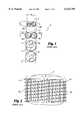
- FIG. 1is a diagrammatic representation of a segment of the human spinal column comprising several vertebrae with various cylindrical threaded implants inserted across the disc space and into the two adjacent vertebrae to illustrate the problems encountered by those implants.
- FIG. 2is a top plan view along lines 2--2 of FIG. 1 with the top vertebrae removed, of two cylindrical threaded implants illustrating the minimum distance possible between the two threaded implants when placed beside each other across the disc space.
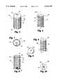
- FIG. 3is a perspective side view of an embodiment of the spinal fusion implant, of the present invention having surface roughenings in the form of ratchetings.
- FIG. 4is a first side elevational view of the spinal fusion implant of FIG. 3.
- FIG. 5is a top plan view of two spinal fusion implants of FIG. 3 illustrating the minimum distance possible between the two implants when placed beside each other across the disc space.
- FIG. 6is a second side elevational view of the spinal fusion implant of FIG. 3.
- FIG. 7is a cross sectional view along lines 7--7 of the spinal fusion implant; of FIG. 6.
- FIG. 8is a cross sectional view along lines 8--8 of the spinal fusion implant of FIG. 6.
- FIG. 9is a top end view of the spinal fusion implant of FIG. 3.
- FIG. 10is a bottom end view of the spinal fusion implant of FIG. 3.
- FIG. 11is a side perspective view of an alternative embodiment of the spinal fusion implant of the present invention.
- FIG. 12is a first side elevational view of the spinal fusion implant of FIG. 11.
- FIG. 13is a second side elevational view of the spinal fusion implant of FIG. 11.
- FIG. 14is cross sectional view along lines 14--14 of the spinal fusion implant of FIG. 13.
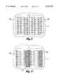
- FIG. 15is a perspective side view of an alternative embodiment of the spinal fusion implant of the present invention having surface roughenings in the form of knurling.
- FIG. 16is a first side elevational view of the spinal fusion implant of FIG. 15.
- FIG. 17is a top plan view of two spinal fusion implants of FIG. 15 illustrating the minimum distance possible between the two implant when placed beside each other across the disc space.
- FIG. 18is an enlarged fragmentary view along line 18 of FIG. 16 showing the surface configuration of the implant of FIG. 15.
- FIG. 19is a second side elevational view of the spinal fusion implant of FIG. 15.
- FIG. 20is a cross sectional view along lines 20--20 of the spinal fusion implant of FIG. 16.
- FIG. 21is a top end view of the spinal fusion implant of FIG. 15.
- FIG. 22is a bottom end view of the spinal fusion implant of FIG. 15.
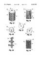
- FIG. 23is a perspective side view of an alternative embodiment of the spinal fusion implant of the present invention having flat sides and surface roughenings in the form of ratchetings.
- FIG. 24is a first side elevational view of the spinal fusion implant of FIG. 23.
- FIG. 25is a diagrammatic representation of a segment of the human spinal column showing two implants of FIG. 23 the present invention inserted within the spine.
- FIG. 26is a top plan view along lines 26--26 of FIG. 25 with the top vertebrae removed, illustrating the minimum distance possible between two spinal fusion implants of FIG. 23 placed beside each other across the disc space.
- FIG. 27is a top end view of the spinal fusion implant of FIG. 23.
- FIG. 28is a bottom end view of the spinal fusion implant of FIG. 23.
- FIG. 29is a second side elevational view of the spinal fusion implant of FIG. 23.
- FIG. 30is a cross sectional view along lines 30--30 of the spinal fusion implant of FIG. 29.
- FIG. 30Ais cross sectional view of an alternative embodiment of the spinal fusion implant of the present invention having only one flat side.
- FIG. 31is a perspective side view of an alternative embodiment of the spinal fusion implant of the present invention having flat sides and surface roughenings in the form of ratchetings.
- FIG. 32is a first side elevational view of the spinal fusion implant of FIG. 31.
- FIG. 33is a second side elevational view of the spinal fusion implant of FIG. 31.
- FIG. 34is a cross sectional view along lines 34--34 of the spinal fusion implant of FIG. 33.
- FIG. 35is a cross sectional view along lines 35--35 of the spinal fusion implant of FIG. 33.
- FIG. 36is a perspective side view of an alternative embodiment of the spinal fusion implant of the present invention having flat sides and having surface roughenings in the form of knurling.
- FIG. 37is a first side elevational view of the spinal fusion implant of FIG. 36.
- FIG. 38is a second side elevational view of the spinal fusion implant of FIG. 36.
- FIG. 39is a cross sectional view along lines 39--39 of the spinal fusion implant of FIG. 38.
- FIG. 40is an enlarged fragmentary view along line 40 of FIG. 37 showing the surface configuration of the spinal fusion implant of FIG. 36.
- FIG. 41is a perspective side view of an alternative embodiment of the spinal fusion implant of the present invention having surface roughenings comprising of a blasted external surface.
- FIG. 42is a perspective side view of an alternative embodiment of the spinal fusion implant of the present invention having flat sides and openings in the form of vertical and horizontal slots.
- FIG. 43is an elevational side view of a segment of the spinal column with an alternative embodiment of two spinal fusion implants of the present invention having corresponding concave and convex sides inserted across one disc space and an alternative embodiment of a single spinal fusion implant of the present invention having a two cylindrical portions inserted across one disc space.
- FIG. 1a diagrammatic representation of a segment of the human spinal column generally referred to by the letter S is shown.
- the segment of the spinal column Scomprises several vertebrae V and a disc space D between two adjacent vertebrae V.
- Various cylindrical threaded spinal fusion implants, each having different diameters,are shown inserted across the disc space D.
- each implant 10a and 10bprotrudes from the sides of the spinal column S and could cause severe and perhaps mortal damage to the patient as delicate and vital structures lie adjacent to that area of the spinal column S such that the use of two cylindrical spinal fusion implants 10a and 10b would not be desirable.
- spinal fusion implant 12awould have a diameter that is significantly greater than the height H s of the disc space D, such that the vertebrae V would have to be substantially bored out to accommodate the large diameter of the spinal fusion implant 12a. As a result, a large part of the vertebrae V would be removed, and thus the overall structural integrity of the vertebrae V would be substantially weakened.
- spinal fusion implants 14a and 14beach having a sufficiently sized diameter such that when placed side-by-side in the disc space D, the combined overall width of the spinal fusion implants 14a and 14b just fills the transverse width W s of the spinal column S, the diameter of each of the spinal fusion implants 14a and 14b will not be sufficient to cross the disc space D to engage the vertebrae V. Therefore, while the spinal fusion implants 14a and 14b will not protrude from the sides of the spinal column S, the spinal fusion implants 14a and 14b cannot reach and engage the bone of the vertebrae V and thus cannot function to stabilize the adjacent vertebrae V.
- FIG. 2a top plan view, taken along line 2--2 of FIG. 1 with the upper vertebrae V removed, of two cylindrical threaded implants 10a and 10b placed across the disc space D is shown.
- the threaded implants 10a and 10bhave an external thread 11a and 11b which must have a minimum height that is proportional to the size of the threaded implant to be effective.
- the thread 11a and 11b of the threaded implants 10a and 10bconverts torque to linear motion, such that the threads 11a and 11b need to be of a sufficient height to overcome the resistance of the material, such as bone, in which the threaded implants 10a and 10b are being inserted, such resistance being proportional to the surface area and diameter of each of threaded implant 10a and 10b.
- each threaded implant 10a and 10bis such that when two threaded implants 10a and 10b are implanted across the disc space D and into the adjacent vertebrae V, there must be a minimum distance between the two threaded implants 10a and 10b to allow for the height of the threads 11a and 11b. This would be true even if the threads 11a and 11b were interdigitated, the threaded implants 10a and 10b would still be offset by at least the height of the thread of at least one of the threaded implants 10a and 10b. Such a minimum distance between the two threaded implants 10a and 10b increases the combined overall width of the two threaded implants 10a and 10b when inserted.
- a cylindrical spinal fusion implantin order for a cylindrical spinal fusion implant to be used in the spinal fusion process where the height H s of the disc space D between two adjacent vertebrae V is large relative to its width W s , it is necessary to have an implant that can be implanted adjacent to a second of its kind in closer contact than is possible with threaded implants, while still providing for an implant surface that will provide mechanical stability in engagement to the adjacent vertebrae V.
- the use of a cylindrical implantis desirable as it is easy to prepare the recipient site by drilling a cylindrical hole across the disc space D and into the adjacent vertebrae V.
- the curved surface of the cylindrical holes drilled into the vertebrae Vhave increased surface area compared to a flat surface and also provides for the possibility of tight congruency when the cylindrical hole is fitted with an implant having corresponding cylindrical portions of matched diameter.
- the spinal fusion implant 100has a substantially cylindrical configuration having a thin outer wall 112 surrounding an internal chamber 114 and a longitudinal central axis L.
- the exterior of the spinal fusion implant 100comprises surface roughenings that provide a surface suitable for engaging the vertebrae V to stabilize the spinal fusion implant 100 across the disc space D and into the adjacent vertebrae V once surgically implanted.
- the surface rougheningscomprise a plurality of ratchetings 120 along the circumference of said spinal fusion implant. Each of the plurality of ratchetings 120 has a bone engaging edge 122 and an angled segment 124.
- Each of the plurality of ratchetings 120has a height that is substantially less than the height of a requisite thread for a cylindrical threaded implant of the same size.
- the requisite height of the threadis proportional to the surface area and diameter of the implant and must be sufficient to pull a cylindrical implant having a diameter sufficient to cross the disc space D through a material as dense as bone.
- the ratchetings 120have a height that is significantly less than the requisite height of a thread of a same sized threaded implant since the spinal fusion implant 100 is implanted across the disc space D and into the adjacent vertebrae V by linear advancement.
- the spinal fusion implant 100may be pushed into the cylindrical disc space D by direct, linear advancement since it requires no thread to pull it forward through the spine. As no torque is required to advance the spinal fusion implant 100 there is no minimum requisite height of the surface roughenings. The only surface feature necessary is that which gives the spinal fusion implant 100 stability once implanted.
- the ratchetings 120may face in one direction, the direction in which the spinal fusion implant 100 is inserted, and function to prevent the spinal fusion implant 100 from backing out of the disc space D in a direction opposite to the direction of insertion once inserted between the two adjacent vertebrae V.
- the ratchetings 120urge the spinal fusion implant 100 forward against the unremoved bone of the vertebrae V. Since implants generally want to back out along the same path in which they are inserted, such as repeated movement of the patient's body over time and which would cause some other design of implant to come loose (e.g. cause a threaded cylindrical implant to possibly unscrew), the ratchetings 120 tend to urge the spinal fusion implant 100 forward against the solid unremoved bone further resisting dislodgement and controlling motion resulting in an exceedingly stable implantation.
- the bone engaging edges 122 of the ratchetings 120that have a height at a highest point measured from the root diameter of the spinal fusion implant 100 that is approximately 0.35 mm. in this manner the spinal fusion implant 100 may be placed beside a second of its kind at a distance of approximately 0.7 mm apart or if offset even closer, substantially reducing the combined overall width of the two spinal fusion implants 100 once surgically implanted.
- the ratchetings 120may have a height in the range of 0.25-1.5 mm, with the preferred height range being 0.35-0.75 mm.
- two spinal fusion implants 100a and 100bare shown inserted across the disc space D having the same dimensions of the disc space D shown in FIG. 2.
- the two spinal fusion implants 100a and 100bhave a decreased overall combined width when compared to two threaded spinal fusion implants placed side by side previously described and illustrated in FIG. 2.
- the decreased combined overall width of the two spinal fusion implants 100a and 100bis the difference between the root and major diameters of the spinal fusion implants 100a and 100b and is achieved by utilizing surface roughenings such as ratchetings 120 for stability.
- the surface rougheningsallow the two spinal fusion implants 100a and 100b to come into considerably closer approximation to one another and require less total transverse width for their insertion than is possible for two threaded cylindrical implants having identical root diameters because of the requisite thread height of such threaded implants. Reducing the offset between implants allows for the uses of larger diameter implants which can then still fit within the transverse width W s of the spinal column and achieve more substantial engagement into the adjacent vertebrae V.
- FIG. 7a cross section of the spinal fusion implant 100 is shown wherein the wall 112 has openings 128 passing therethrough to communicate with the internal chamber 114.
- the internal chamber 114may be filled with bone material or any natural or artificial bone growth material or fusion promoting material such that bone growth occurs from the vertebrae V through the openings 128 to the material within internal chamber 114.
- the openings 128have been shown in the drawings as being circular, it is appreciated that the openings 128 may have any shape, size, or form suitable for use in a spinal fusion implant without departing from the scope of the present invention. Also, the number of openings may be varied or no openings may be present on the spinal fusion implant.
- the spinal fusion implant 100has a cap 130 with a thread 132 that threadably attaches to one end of the spinal fusion implant 100.
- the edge 136acts as an additional ratcheting 120 to further stabilize the spinal fusion implant 100 once it is implanted across the disc space D.
- the cap 130is removable to provide access to the internal chamber 114, such that the internal chamber 114 can be filled and hold any natural or artificial osteoconductive, osteoinductive, osteogenic, or other fusion enhancing material.
- Some examples of such materialsare bone harvested from the patient, or bone growth inducing material such as, but not limited to, hydroxyapatite, hydroxyapatite tricalcium phosphate; or bone morphogenic protein.
- the cap 130 and/or the spinal fusion implant 100 itselfis made of material appropriate for human implantation such as titanium and/or may be made of, and/or filled and/or coated with a bone ingrowth inducing material such as, but not limited to, hydroxyapatite or hydroxyapatite tricalcium phosphate or any other osteoconductive, osteoinductive, osteogenic, or other fusion enhancing material.
- a bone ingrowth inducing materialsuch as, but not limited to, hydroxyapatite or hydroxyapatite tricalcium phosphate or any other osteoconductive, osteoinductive, osteogenic, or other fusion enhancing material.
- the cap 130amay be "bullet"-shaped to facilitate insertion.
- the cap 130ahas at its greatest diameter a diameter equal to the root diameter of the spinal fusion implant 100 such that no additional ratchetings 120 are formed.
- the spinal fusion implant 100has an engagement means at one end in the form of a rectangular slot 140 for engaging a driver instrument having a removable engagement means for intimately engaging the rectangular slot 140.
- a threaded portion of the driver instrumentwhich in one embodiment extends as a rod through a hollow tubular member and can be rotationally controlled, screws into a threaded aperture 142 in the slot 140 and binds the implant 100 and the driver instrument together.
- the spinal fusion implant 100may be then introduced through a hollow cylindrical tube and driven into the cylindrical hole that has been drilled across the disc space D.
- the implant driver instrumentmay then be impacted by a mallet, or similar device, to linearly advance the spinal fusion implant 100 across the disc space D.
- FIGS. 11-14an alternative embodiment of the spinal fusion implant of the present invention, generally referred to by the numeral 200 is shown.
- the spinal fusion implant 200is similar to the spinal fusion implant 100 except that the openings 228 are bisected by the bone engaging edge 222 of the plurality of ratchetings 220. In this manner, the bone engaging edges are interrupted by the openings 228 to provide a "tooth-like" edge that engages the bone of the vertebrae V and creates an interference fit to prevent the backing out of the implant 200 once inserted. It is appreciated that the number of openings 228 and the number of bone engaging edges 222 may be varied and that the opening 228 can be placed in any orientation relative to the ratchetings 220 or other surface roughening without departing from the scope of the present invention.
- the spinal fusion implant 300has a substantially cylindrical configuration having surface roughenings for stabilizing the implant 300 within the intervertebral space D.
- the surface rougheningscomprise a surface knurling 320 such as, but not limited to, the diamond-shaped bone engaging pattern shown.
- the spinal fusion implant 300may have surface knurling 320 throughout the entire external surface of the spinal fusion implant 300, throughout only a portion of the external surface, or any combination thereof, without departing from the scope of the present invention.
- surface knurling 320is preferred as it produces an exceedingly high interference fit with the bone of the vertebrae V and resists motion equally in all directions and without the tendency to urge itself forward.
- two spinal fusion implants 300a and 300bmay be placed side by side across the disc space D having the same dimensions of the disc space D shown in FIG. 2, such that the two spinal fusion implants 300a and 300b are touching each other and thus reducing the overall combined width of the two spinal implants 300a and 300b to the minimum distance possible with a substantially cylindrical implant having a roughened surface.
- two cylindrical spinal fusion implants 300a and 300b having a sufficient diameter to cross the height H s of the disc space Dcan be placed across the disc space D without exceeding the transverse width W s of the spinal column S.
- the spinal fusion implants 300a and 300bare inserted by linear advancement as described above for spinal fusion implant 100.
- spinal fusion implants 300a and 300bmay be placed closer together to substantially reduce the overall combined width of two such implants.
- the spinal fusion implant 400has a similar configuration to that of the spinal fusion implant 200, except that it comprises a partially cylindrical member having arcuate portions 402 and 404 which are arcs of the same circle with portions of its outer wall 405 that are flattened so as to present a first flat side 406 and a second flat side 408.
- the spinal fusion implant 400has a major diameter M equal to the distance between two diametrically opposite non-flattened segments, such as arcuate portions 402 and 404 which are arcs of the same circle.
- the width W i of the spinal fusion implant 400is equal to the distance between a flattened segment and a point diametrically opposite the flattened segment, such as the distance between the first and second flat sides 406 and 408.
- FIG. 25a diagrammatic representation of a segment of a spinal column S comprising several vertebrae V is shown having two spinal fusion implants 400a and 400b inserted across the disc space D between the two adjacent vertebrae V.
- the spinal fusion implants 400a and 400bare identical and each has a first arcuate portion 402a and 402b, respectively; a second arcuate portion 404a and 404b, respectively; a first flat side 406a and 406b, respectively; and a second flat side 408a and 408b, respectively.
- the spinal fusion implants 400a and 400bare implanted across the disc space D with the second flat side 408a of spinal fusion implant 400a facing and adjacent to the first flat side 408b of spinal fusion implant 400b such that the combined overall width of the two spinal fusion implants 400a and 400b is less than twice the maximum diameter M of the implants.
- the spinal fusion implants 400a and 400bare inserted by linear advancement as described above for spinal fusion implant 100.
- two partially overlapping cylindrical holesare drilled across the disc space D and into the adjacent vertebrae V.
- the holesare drilled sufficiently overlapping to allow the two spinal fusion implants 400a and 400b to be implanted with the flat sides perpendicular to the plane of the disc space D, the disc space D being in a plane perpendicular to the longitudinal vertical axis A of the spinal column S as shown in FIG. 25.
- the spinal fusion implants 400a and 400bmay be inserted separately such that once a first spinal fusion implant 400a is inserted across the disc space D, a second spinal fusion implant 400b is driven across the disc space D so that the flat side 402 or 404 of each spinal fusion implant 400 are adjacent to each other and are touching. In this manner, the two spinal fusion implants 400a and 400b are implanted across the disc space D and engage the bone of the adjacent vertebrae V without exceeding the transverse width W s of the spinal column S.
- the two spinal fusion implants 400a and 400bmay be implanted across the disc space D simultaneously by placing them adjacent and facing each other, in the orientation described above, prior to implantation. The two spinal fusion implants 400a and 400b are then linearly advanced into the drilled holes across the disc space D.
- the effect of having first and second flat sides 406 and 408is that the overall width W i of the spinal fusion implant 400 is substantially reduced while the height of the spinal fusion implant 400 remains the maximum diameter M of the cylindrical portion of the spinal fusion implant 400.
- each spinal fusion implant 400a and 400bengages the bone of the adjacent vertebrae V while the combined width of the two spinal fusion implant 100 does not exceed the transverse width W s of the spinal column S.
- the advantages of placing two cylindrical implants side by side across the disc space Dmay be obtained without exceeding the width W s of the spinal column S.
- the two spinal fusion implants 400a and 400bcan be inserted across the disc space D, having the same dimensions as the disc space D shown in FIG. 2, and can be placed much closer together as a result of the first flat side 408b placed adjacent to the second flat side 408a while continuing to engage the adjacent vertebrae V.
- the spinal fusion implant 400has a hollow internal central chamber 414 and has a series of openings 428 passing through the outer wall 405 and into the central chamber 414 of the spinal fusion implant 400.
- the openings 428may also be present on the first and second flat sides 406 and 408.
- Said openings 428 while shown as round holes for example,may be any other workable configuration consistent with their purpose and may include, but is not limited to, ovals, slots, grooves and holes that are not round as is true for any of the cylindrical implants disclosed above.
- the spinal fusion implant 400'could have only one flat side so as to provide only a first flat side 406'. This configuration is appropriate where the width W i of the spinal fusion implant 400 need only be slightly reduced with respect to its maximum diameter M, to prevent the combined overall width of two such implants from exceeding the transverse width W s of the spinal column S.
- the spinal fusion implant 400 of the present inventionhas a plurality of ratchetings 420 facing one direction, as described above for spinal fusion implant 100, along the outer surface of the cylindrical portion of the circumference of the spinal fusion implant 400.
- the ratchetings 420have a bone engaging edges 422 and the angled configuration of the ratchetings 420 provide for a "one-way" insertion of the spinal fusion implant 400 as the movement of the spinal fusion implant 400 in the opposite way is prevented by the engagement or the engaging edges 422 with the vertebrae V.
- the flat sides 402 and 404are preferably smooth and have a flat surface so as to allow placement in the closest possible proximity of the two spinal fusion implants 400a and 400b.
- the bone engaging edge 422 of each ratcheting 420bisects the holes 428 to increase the stability of the spinal fusion implant 400 once implanted.
- the spinal fusion implants 100-600each have an overall length in the range of 20 mm to 30 mm, with 25 mm being preferred, and a maximum diameter M in the range of 14 mm to 24 mm, with 18 mm being preferred when inserted in the lumbar spine from the posterior approach, and 20 mm being preferred when inserted in the lumbar spine from the anterior approach.
- the spinal fusion implant 400is quite appropriate for use in the cervical and thoracic spine as well. In the cervical spine such implants would have a length in the range of 10-18 mm preferred 12 mm and a maximum diameter M in the range of 12-20 mm, with the preferred diameter being 16 mm.
- spinal fusion implants 400-600have a width W i for use in the cervical spine in the range of 8-16 mm, with the preferred width W i being 10-14 mm; for use in the lumbar spine in the range of 18-26 mm, with the preferred width W s being 18-20 mm; and for use in the lumbar spine in the range of 18-26 mm, with the preferred width W i being 20-24 mm.
- the spinal fusion implant 400 of the present inventionhas externally the geometrical configuration of a circle with a portion of each side tangentially amputated vertically to form the first and second flat sides 406 and 408.
- the cap 430extends beyond the narrowest diameter of the wall 412 along the first and second arcuate portions 402 and 404 at the end of the spinal fusion implant 400 and acts as an additional ratcheting 420 with an engaging edge 436.
- the additional ratcheting 420functions to further increase the stability of the spinal fusion implant 400 once inserted between the adjacent vertebrae V and to further prevent the dislodgement of the spinal fusion implant 400 from the disc space D.
- the cap 430is flush with the flat sides 406 and 408 to preserve the flat surfaces of flat sides 406 and 408.
- the cap 430further has a sloping sides 438a and 438b corresponding position with the flat sides 406 and 408 to facilitate insertion of the spinal fusion implant 400 and to permit for close side by side placement of two spinal fusion implants 400.
- the cap 430can be flush all the way around with the root diameter of the spinal fusion implant 400 to further facilitate insertion for a longer ramp length.
- the spinal fusion implant 400has surface roughenings such as, but not limited to, ratchetings 420 such that the outer surface of the spinal fusion implant 400 may have a plurality of other surface roughenings to enhance the stability of the spinal fusion implant 400 and to resist dislodgement once implanted across the disc space D.
- the spinal fusion implant 400may have an irregular outer surface that may be created by blasting or rough casting and the like. Such an irregular surface may be used alone or in combination with other surface roughenings such as ratchetings and/or knurling and as already discussed, the openings 428 may be holes, grooves, slots or other.
- the spinal fusion implant 500is substantially the same as the spinal fusion implant 400, except that the openings 528 are positioned on the ratcheting 520 such that the openings 528 are positioned between the bone engaging edges 522 and are not bisected by the bone engaging edges 522. In this manner the bone engaging edges 522 are continuous and uninterrupted to engage the bone of the vertebrae V and prevent the backing out of the implant 500 once inserted.
- the spinal fusion implant 600is substantially identical to the spinal fusion implant 400 described above except that in place of ratchetings 420, it has surface knurling 620 such as, but not limited to, the diamond-shaped bone engaging pattern shown in FIG. 40.
- the surface knurling 620assists in the retaining of the spinal fusion implant 600 once it is inserted across the disc space D between two adjacent vertebrae V.
- the surface knurling 620 of the implant 600may be combined with any of a number of other surface roughenings such as, but not limited to, ratchetings to assist in retaining the spinal fusion implant 600 ac ross the disc space D.
- the cap 630 of the spinal fusion implant 600has sloping sides 660 and 662 corresponding with the first and second flat sides 606 and 608 to facilitate insertion of the spinal fusion implant 600 and to permit for close side by side placement of two spinal fusion implants 600.
- the implant inventionmay include any and all surface roughening configuration that either increase the surface are a or interference fit of the implant and the vertebrae V. It is appreciated that the ratchetings described above for the various embodiments of the spinal fusion implants of the present invention may also comprise a knurled or other surface roughenings in combination with the ratchetings to further enhance the retention of the spinal fusion implant across the disc space D once inserted.
- the spinal fusion implant 700has surface roughenings comprising of a blasted external surface 701 to provide an engagement surface for the vertebrae V when inserted across the disc space D.
- the spinal fusion implanthas a plurality of openings 728, a removable cap 730 with a hex slot 734 for engaging a hex tool.
- FIG. 42an alternative embodiment of the spinal fusion implant of the present invention generally referred to by the numeral 800 is shown.
- the spinal fusion implant 800is similar to spinal fusion implant 400 described above except that it has openings in the form of horizontal slots 828 on the flat side 806 and vertical slots 829 on the cylindrical portion of the spinal fusion implant 800.
- the spinal implants of the present inventionmay have any configuration such that the combined overall width of the two such spinal fusion implants is less than twice the maximum diameter M of those implants without departing from the scope of the present invention.
- a segment of the spinal column Sis shown with an alternative embodiment of two spinal fusion implants 900a and 900b inserted across disc space D 1 is shown.
- Spinal fusion implant 900ahas a concave surface 902 which is correspondingly shaped for receiving the convex surface 904 of spinal fusion implant 900b.
- the concave surface 902mates with the convex surface 904 such that the combined overall width of the two spinal fusion implants is less than twice the maximum diameter M of those implants.
- the spinal fusion implant 1000comprises a first cylindrical portion 1010 and a second cylindrical portion 1012 and may have any of the surface roughenings described above in reference to the embodiments set forth above.
- the spinal fusion implant 1000is inserted by linear advancement into two overlapping cylindrical holes drilled across the disc space D 2 .
Landscapes
- Health & Medical Sciences (AREA)
- Engineering & Computer Science (AREA)
- Biomedical Technology (AREA)
- Orthopedic Medicine & Surgery (AREA)
- Life Sciences & Earth Sciences (AREA)
- Surgery (AREA)
- Oral & Maxillofacial Surgery (AREA)
- Heart & Thoracic Surgery (AREA)
- Veterinary Medicine (AREA)
- Animal Behavior & Ethology (AREA)
- General Health & Medical Sciences (AREA)
- Public Health (AREA)
- Transplantation (AREA)
- Neurology (AREA)
- Cardiology (AREA)
- Dentistry (AREA)
- Nuclear Medicine, Radiotherapy & Molecular Imaging (AREA)
- Vascular Medicine (AREA)
- Medical Informatics (AREA)
- Molecular Biology (AREA)
- Physical Education & Sports Medicine (AREA)
- Prostheses (AREA)
Abstract
Description
Claims (24)
Priority Applications (2)
| Application Number | Priority Date | Filing Date | Title |
|---|---|---|---|
| US08/723,597US6123705A (en) | 1988-06-13 | 1996-10-01 | Interbody spinal fusion implants |
| US09/641,865US6758849B1 (en) | 1995-02-17 | 2000-08-18 | Interbody spinal fusion implants |
Applications Claiming Priority (5)
| Application Number | Priority Date | Filing Date | Title |
|---|---|---|---|
| US07/205,935US5015247A (en) | 1988-06-13 | 1988-06-13 | Threaded spinal implant |
| US69867491A | 1991-05-10 | 1991-05-10 | |
| US07/968,240US5741253A (en) | 1988-06-13 | 1992-10-29 | Method for inserting spinal implants |
| US48283795A | 1995-06-07 | 1995-06-07 | |
| US08/723,597US6123705A (en) | 1988-06-13 | 1996-10-01 | Interbody spinal fusion implants |
Related Parent Applications (3)
| Application Number | Title | Priority Date | Filing Date |
|---|---|---|---|
| US07/968,240Continuation-In-PartUS5741253A (en) | 1988-06-13 | 1992-10-29 | Method for inserting spinal implants |
| US08/390,131DivisionUS5593409A (en) | 1988-06-13 | 1995-02-17 | Interbody spinal fusion implants |
| US48283795AContinuation | 1988-06-13 | 1995-06-07 |
Related Child Applications (1)
| Application Number | Title | Priority Date | Filing Date |
|---|---|---|---|
| US09/641,865ContinuationUS6758849B1 (en) | 1995-02-17 | 2000-08-18 | Interbody spinal fusion implants |
Publications (1)
| Publication Number | Publication Date |
|---|---|
| US6123705Atrue US6123705A (en) | 2000-09-26 |
Family
ID=27498595
Family Applications (1)
| Application Number | Title | Priority Date | Filing Date |
|---|---|---|---|
| US08/723,597Expired - LifetimeUS6123705A (en) | 1988-06-13 | 1996-10-01 | Interbody spinal fusion implants |
Country Status (1)
| Country | Link |
|---|---|
| US (1) | US6123705A (en) |
Cited By (215)
| Publication number | Priority date | Publication date | Assignee | Title |
|---|---|---|---|---|
| USD458373S1 (en) | 2000-09-21 | 2002-06-04 | Roger P. Jackson | Interbody spinal implant |
| US6436141B2 (en) | 2000-04-07 | 2002-08-20 | Surgical Dynamics, Inc. | Apparatus for fusing adjacent bone structures |
| US20020116066A1 (en)* | 1996-09-13 | 2002-08-22 | Jean-Luc Chauvin | Expandable osteosynthesis cage |
| US6440170B1 (en)* | 2000-12-04 | 2002-08-27 | Roger P. Jackson | Threaded interbody device |
| US20020138147A1 (en)* | 2001-03-22 | 2002-09-26 | Surgical Dynamics, Inc. | Apparatus for fusing adjacent bone structures |
| US6544265B2 (en) | 2000-11-08 | 2003-04-08 | The Cleveland Clinic Foundation | Apparatus for implantation into bone related applications |
| US6551319B2 (en) | 2000-11-08 | 2003-04-22 | The Cleveland Clinic Foundation | Apparatus for implantation into bone |
| US6558386B1 (en) | 2000-02-16 | 2003-05-06 | Trans1 Inc. | Axial spinal implant and method and apparatus for implanting an axial spinal implant within the vertebrae of the spine |
| US6558390B2 (en) | 2000-02-16 | 2003-05-06 | Axiamed, Inc. | Methods and apparatus for performing therapeutic procedures in the spine |
| US20030097181A1 (en)* | 1999-04-07 | 2003-05-22 | Salvatore Castro | Low profile fusion cage and insertion set |
| US6575981B1 (en) | 1999-02-04 | 2003-06-10 | Sdgi Holdings, Inc. | Methods and instrumentation for vertebral interbody fusion |
| US6582437B2 (en) | 1999-08-26 | 2003-06-24 | Sdgi Holdings, Inc. | Devices and methods for implanting fusion cages |
| US20030181913A1 (en)* | 2000-10-05 | 2003-09-25 | The Cleveland Clinic Foundation | Apparatus for implantation into bone |
| US6648895B2 (en) | 2000-02-04 | 2003-11-18 | Sdgi Holdings, Inc. | Methods and instrumentation for vertebral interbody fusion |
| US20030233145A1 (en)* | 2002-03-11 | 2003-12-18 | Landry Michael E. | Instrumentation and procedure for implanting spinal implant devices |
| US6689168B2 (en) | 2000-10-05 | 2004-02-10 | The Cleveland Clinic Foundation | Method and apparatus for stabilizing adjacent bones |
| US6726722B2 (en)* | 2000-10-24 | 2004-04-27 | Howmedica Osteonics Corp. | Threaded apparatus for fusing adjacent bone structure |
| US6740090B1 (en) | 2000-02-16 | 2004-05-25 | Trans1 Inc. | Methods and apparatus for forming shaped axial bores through spinal vertebrae |
| US6743234B2 (en) | 1999-02-04 | 2004-06-01 | Sdgi Holdings, Inc. | Methods and instrumentation for vertebral interbody fusion |
| US6758849B1 (en) | 1995-02-17 | 2004-07-06 | Sdgi Holdings, Inc. | Interbody spinal fusion implants |
| US20040162616A1 (en)* | 2002-10-21 | 2004-08-19 | Simonton T. Andrew | Systems and techniques for restoring and maintaining intervertebral anatomy |
| US20040167628A1 (en)* | 2002-10-21 | 2004-08-26 | Foley Kevin T. | Systems and techniques for restoring and maintaining intervertebral anatomy |
| US6783547B2 (en) | 2002-04-05 | 2004-08-31 | Howmedica Corp. | Apparatus for fusing adjacent bone structures |
| US20050049587A1 (en)* | 2003-08-27 | 2005-03-03 | Jackson Roger P. | Threaded device for implantation between vertebrae |
| US20050049704A1 (en)* | 2003-08-29 | 2005-03-03 | Jackson Roger P. | Convex spinal fusion interbody spacer |
| US20050065606A1 (en)* | 2003-09-18 | 2005-03-24 | Jackson Roger P. | Threaded center line cage with winged end cap |
| USD503801S1 (en) | 2004-04-05 | 2005-04-05 | Roger P. Jackson | Interbody spacer for spinal implantation |
| US6899716B2 (en) | 2000-02-16 | 2005-05-31 | Trans1, Inc. | Method and apparatus for spinal augmentation |
| US6902581B2 (en)* | 2000-10-24 | 2005-06-07 | Kowmedica Osteonics Corp. | Apparatus for fusing adjacent bone structure |
| US20050149188A1 (en)* | 2002-02-07 | 2005-07-07 | Cook Stephen D. | Anterior spinal implant |
| US6942698B1 (en) | 2004-04-23 | 2005-09-13 | Roger P. Jackson | Spinal fusion interbody spacer |
| US20050222681A1 (en)* | 2002-06-17 | 2005-10-06 | Richard Richley | Devices and methods for minimally invasive treatment of degenerated spinal discs |
| US20050244451A1 (en)* | 2004-05-03 | 2005-11-03 | Robert Diaz | Method and device for reducing susceptibility to fractures in vertebral bodies |
| US20050244499A1 (en)* | 2004-05-03 | 2005-11-03 | Robert Diaz | Method and device for reducing susceptibility to fractures in long bones |
| US20050251258A1 (en)* | 2004-05-10 | 2005-11-10 | Jackson Roger P | Vertebral interbody spacer |
| US6966910B2 (en) | 2002-04-05 | 2005-11-22 | Stephen Ritland | Dynamic fixation device and method of use |
| US6966929B2 (en) | 2002-10-29 | 2005-11-22 | St. Francis Medical Technologies, Inc. | Artificial vertebral disk replacement implant with a spacer |
| US6979353B2 (en) | 2001-12-03 | 2005-12-27 | Howmedica Osteonics Corp. | Apparatus for fusing adjacent bone structures |
| US20060004450A1 (en)* | 1997-12-10 | 2006-01-05 | Mckay William F | Osteogenic fusion device |
| US6991632B2 (en) | 2001-09-28 | 2006-01-31 | Stephen Ritland | Adjustable rod and connector device and method of use |
| US20060085077A1 (en)* | 2004-10-18 | 2006-04-20 | Ebi, L.P. | Intervertebral implant and associated method |
| US20060089642A1 (en)* | 2004-10-27 | 2006-04-27 | Diaz Robert L | Prefracture spinal implant for osteoporotic unfractured bone |
| US20060111714A1 (en)* | 1999-10-20 | 2006-05-25 | Foley Kevin T | Instruments and methods for stabilization of bony structures |
| US20060142858A1 (en)* | 2004-12-16 | 2006-06-29 | Dennis Colleran | Expandable implants for spinal disc replacement |
| US7083649B2 (en) | 2002-10-29 | 2006-08-01 | St. Francis Medical Technologies, Inc. | Artificial vertebral disk replacement implant with translating pivot point |
| US7087058B2 (en) | 2000-02-16 | 2006-08-08 | Trans1, Inc. | Method and apparatus for providing posterior or anterior trans-sacral access to spinal vertebrae |
| US7166073B2 (en) | 2000-09-29 | 2007-01-23 | Stephen Ritland | Method and device for microsurgical intermuscular spinal surgery |
| US7207992B2 (en) | 2001-09-28 | 2007-04-24 | Stephen Ritland | Connection rod for screw or hook polyaxial system and method of use |
| US7214186B2 (en) | 2000-09-29 | 2007-05-08 | Stephen Ritland | Method and device for retractor for microsurgical intermuscular lumbar arthrodesis |
| US20070173938A1 (en)* | 2006-01-26 | 2007-07-26 | Spinal Generations, Llc | Interbody cage system |
| US7273496B2 (en) | 2002-10-29 | 2007-09-25 | St. Francis Medical Technologies, Inc. | Artificial vertebral disk replacement implant with crossbar spacer and method |
| US7291170B2 (en) | 2000-05-18 | 2007-11-06 | Ldr Medical | Intersomatic cage with unified grafts |
| US7320707B2 (en) | 2003-11-05 | 2008-01-22 | St. Francis Medical Technologies, Inc. | Method of laterally inserting an artificial vertebral disk replacement implant with crossbar spacer |
| US20080082172A1 (en)* | 2006-09-29 | 2008-04-03 | Jackson Roger P | Interspinous process spacer |
| US20080133015A1 (en)* | 2004-04-26 | 2008-06-05 | Beat Lechmann | Intervertebral Prosthesis or Disk Prosthesis |
| US20080262623A1 (en)* | 2005-05-06 | 2008-10-23 | Titan Spine, Llc | Composite interbody spinal implant having openings of predetermined size and shape |
| US20080269901A1 (en)* | 2007-04-27 | 2008-10-30 | Baynham Bret O | Spinal implant |
| US20080275506A1 (en)* | 2007-04-27 | 2008-11-06 | Baynham Bret O | Spinal implant |
| US7455639B2 (en) | 2004-09-20 | 2008-11-25 | Stephen Ritland | Opposing parallel bladed retractor and method of use |
| US7481839B2 (en) | 2003-12-02 | 2009-01-27 | Kyphon Sarl | Bioresorbable interspinous process implant for use with intervertebral disk remediation or replacement implants and procedures |
| US7481840B2 (en) | 2004-09-29 | 2009-01-27 | Kyphon Sarl | Multi-piece artificial spinal disk replacement device with selectably positioning articulating element |
| US20090036927A1 (en)* | 2007-05-22 | 2009-02-05 | Tov Vestgaarden | Method and apparatus for spinal facet fusion |
| US7497859B2 (en) | 2002-10-29 | 2009-03-03 | Kyphon Sarl | Tools for implanting an artificial vertebral disk |
| US20090062916A1 (en)* | 2007-08-27 | 2009-03-05 | Biomedical Enterprises, Inc. | Method and apparatus for an osteotomy fixation or arthrodesis cage |
| US7500977B2 (en) | 2003-10-23 | 2009-03-10 | Trans1 Inc. | Method and apparatus for manipulating material in the spine |
| US7503935B2 (en) | 2003-12-02 | 2009-03-17 | Kyphon Sarl | Method of laterally inserting an artificial vertebral disk replacement with translating pivot point |
| US7537616B1 (en)* | 1999-10-20 | 2009-05-26 | Warsaw Orthopedic, Inc. | Impacted orthopedic bone support implant |
| US7544208B1 (en) | 2004-05-03 | 2009-06-09 | Theken Spine, Llc | Adjustable corpectomy apparatus |
| US7547317B2 (en) | 2000-02-16 | 2009-06-16 | Trans1 Inc. | Methods of performing procedures in the spine |
| US7575600B2 (en) | 2004-09-29 | 2009-08-18 | Kyphon Sarl | Artificial vertebral disk replacement implant with translating articulation contact surface and method |
| US7594931B2 (en) | 2001-07-13 | 2009-09-29 | Ldr Medical | Vertebral cage device with modular fixation |
| US7608077B2 (en) | 2000-02-16 | 2009-10-27 | Trans1 Inc. | Method and apparatus for spinal distraction and fusion |
| US7641657B2 (en) | 2003-06-10 | 2010-01-05 | Trans1, Inc. | Method and apparatus for providing posterior or anterior trans-sacral access to spinal vertebrae |
| US7662185B2 (en) | 1999-12-30 | 2010-02-16 | Osteotech, Inc. | Intervertebral implants |
| US7666227B2 (en) | 2005-08-16 | 2010-02-23 | Benvenue Medical, Inc. | Devices for limiting the movement of material introduced between layers of spinal tissue |
| US7670377B2 (en) | 2003-11-21 | 2010-03-02 | Kyphon Sarl | Laterally insertable artifical vertebral disk replacement implant with curved spacer |
| US7682375B2 (en) | 2002-05-08 | 2010-03-23 | Stephen Ritland | Dynamic fixation device and method of use |
| US7726002B2 (en) | 2001-12-05 | 2010-06-01 | Osteotech, Inc. | Processes for making spinal intervertebral implant, interconnections for such implant |
| US7727263B2 (en) | 2000-02-16 | 2010-06-01 | Trans1, Inc. | Articulating spinal implant |
| US7736380B2 (en) | 2004-12-21 | 2010-06-15 | Rhausler, Inc. | Cervical plate system |
| US7753939B2 (en) | 2000-06-30 | 2010-07-13 | Stephen Ritland | Polyaxial connection device and method |
| US7763047B2 (en) | 2002-02-20 | 2010-07-27 | Stephen Ritland | Pedicle screw connector apparatus and method |
| US7780708B2 (en) | 2000-10-20 | 2010-08-24 | Osteotech, Inc. | Implant retaining device |
| US7780676B2 (en) | 2006-07-11 | 2010-08-24 | Ebi, Llc | Intervertebral implantation apparatus |
| US20100228296A1 (en)* | 2009-03-04 | 2010-09-09 | Robert Tod Vraney | Implant for mammalian bony segment stabilization |
| USD623746S1 (en)* | 2008-06-25 | 2010-09-14 | Globus Medical, Inc. | Spinal implant |
| US7837732B2 (en) | 2003-11-20 | 2010-11-23 | Warsaw Orthopedic, Inc. | Intervertebral body fusion cage with keels and implantation methods |
| US7905908B2 (en) | 2000-02-16 | 2011-03-15 | Trans1, Inc. | Spinal mobility preservation method |
| US7918876B2 (en) | 2003-03-24 | 2011-04-05 | Theken Spine, Llc | Spinal implant adjustment device |
| US7959564B2 (en) | 2006-07-08 | 2011-06-14 | Stephen Ritland | Pedicle seeker and retractor, and methods of use |
| US7976549B2 (en) | 2006-03-23 | 2011-07-12 | Theken Spine, Llc | Instruments for delivering spinal implants |
| US7988695B2 (en) | 2005-12-21 | 2011-08-02 | Theken Spine, Llc | Articulated delivery instrument |
| US8021399B2 (en) | 2005-07-19 | 2011-09-20 | Stephen Ritland | Rod extension for extending fusion construct |
| US20110238183A1 (en)* | 2009-09-26 | 2011-09-29 | Maly Richard S | Interbody Fusion Device |
| US8142508B1 (en) | 2007-07-02 | 2012-03-27 | Theken Spine, Llc | Spinal cage having deployable member which is removable |
| US8241359B2 (en) | 2006-02-15 | 2012-08-14 | Ldr Medical | Transforaminal intersomatic cage for an intervertebral fusion graft and an instrument for implanting the cage |
| US8262571B2 (en) | 2003-05-22 | 2012-09-11 | Stephen Ritland | Intermuscular guide for retractor insertion and method of use |
| US8267997B2 (en) | 2007-11-12 | 2012-09-18 | Theken Spine, Llc | Vertebral interbody compression implant |
| US8292958B1 (en) | 2007-07-02 | 2012-10-23 | Theken Spine, Llc | Spinal cage having deployable member |
| US8313528B1 (en) | 2008-03-27 | 2012-11-20 | Spinelogik, Inc. | Intervertebral fusion device and method of use |
| US8333985B2 (en) | 2004-01-27 | 2012-12-18 | Warsaw Orthopedic, Inc. | Non-glycerol stabilized bone graft |
| US8333804B1 (en) | 2008-03-27 | 2012-12-18 | Spinelogik, Inc. | Intervertebral fusion device and method of use |
| US8343219B2 (en) | 2007-06-08 | 2013-01-01 | Ldr Medical | Intersomatic cage, intervertebral prosthesis, anchoring device and implantation instruments |
| US8366773B2 (en) | 2005-08-16 | 2013-02-05 | Benvenue Medical, Inc. | Apparatus and method for treating bone |
| US8372157B2 (en) | 2007-02-12 | 2013-02-12 | Warsaw Orthopedic, Inc. | Joint revision implant |
| US8403991B2 (en) | 2005-05-06 | 2013-03-26 | Titan Spine Llc | Implant with critical ratio of load bearing surface area to central opening area |
| US8435302B2 (en) | 2005-05-06 | 2013-05-07 | Titan Spine, Llc | Instruments and interbody spinal implants enhancing disc space distraction |
| US8454617B2 (en) | 2005-08-16 | 2013-06-04 | Benvenue Medical, Inc. | Devices for treating the spine |
| US8480749B2 (en) | 2005-05-06 | 2013-07-09 | Titan Spine, Llc | Friction fit and vertebral endplate-preserving spinal implant |
| US8480715B2 (en) | 2007-05-22 | 2013-07-09 | Zimmer Spine, Inc. | Spinal implant system and method |
| US8480745B2 (en) | 1997-08-26 | 2013-07-09 | Warsaw Orthopedic, Inc. | Spinal implant and cutting tool preparation accessory for mounting the implant |
| US8506636B2 (en) | 2006-09-08 | 2013-08-13 | Theken Spine, Llc | Offset radius lordosis |
| US8535327B2 (en) | 2009-03-17 | 2013-09-17 | Benvenue Medical, Inc. | Delivery apparatus for use with implantable medical devices |
| US8545562B1 (en) | 2007-07-02 | 2013-10-01 | Theken Spine, Llc | Deployable member for use with an intervertebral cage |
| US8545568B2 (en) | 2005-05-06 | 2013-10-01 | Titan Spine, Llc | Method of using instruments and interbody spinal implants to enhance distraction |
| US8551176B2 (en) | 2005-05-06 | 2013-10-08 | Titan Spine, Llc | Spinal implant having a passage for enhancing contact between bone graft material and cortical endplate bone |
| US8562685B2 (en) | 2005-05-06 | 2013-10-22 | Titan Spine, Llc | Spinal implant and integration plate for optimizing vertebral endplate contact load-bearing edges |
| US8562684B2 (en) | 2005-05-06 | 2013-10-22 | Titan Spine, Llc | Endplate-preserving spinal implant with an integration plate having a roughened surface topography |
| US8585766B2 (en) | 2005-05-06 | 2013-11-19 | Titan Spine, Llc | Endplate-preserving spinal implant with an integration plate having durable connectors |
| US8585767B2 (en) | 2005-05-06 | 2013-11-19 | Titan Spine, Llc | Endplate-preserving spinal implant with an integration plate having durable connectors |
| US8585765B2 (en) | 2005-05-06 | 2013-11-19 | Titan Spine, Llc | Endplate-preserving spinal implant having a raised expulsion-resistant edge |
| US8591590B2 (en) | 2005-05-06 | 2013-11-26 | Titan Spine, Llc | Spinal implant having a transverse aperture |
| US8591583B2 (en) | 2005-08-16 | 2013-11-26 | Benvenue Medical, Inc. | Devices for treating the spine |
| USD696399S1 (en) | 2008-02-06 | 2013-12-24 | Kleiner Intellectual Property, Llc | Spinal distraction instrument |
| US8617248B2 (en) | 2005-05-06 | 2013-12-31 | Titan Spine, Llc | Spinal implant having variable ratios of the integration surface area to the axial passage area |
| US8679189B1 (en)* | 2013-02-11 | 2014-03-25 | Amendia Inc. | Bone growth enhancing implant |
| US8685031B2 (en) | 2009-09-18 | 2014-04-01 | Spinal Surgical Strategies, Llc | Bone graft delivery system |
| US8721722B2 (en) | 2004-10-18 | 2014-05-13 | Ebi, Llc | Intervertebral implant and associated method |
| US8740983B1 (en) | 2009-11-11 | 2014-06-03 | Nuvasive, Inc. | Spinal fusion implants and related methods |
| US8758442B2 (en) | 2005-05-06 | 2014-06-24 | Titan Spine, Llc | Composite implants having integration surfaces composed of a regular repeating pattern |
| US8758443B2 (en) | 2005-05-06 | 2014-06-24 | Titan Spine, Llc | Implants with integration surfaces having regular repeating surface patterns |
| US20140188225A1 (en)* | 2012-12-14 | 2014-07-03 | Facet-Link Inc. | Intervertebral cage expandable in steps |
| US8808294B2 (en) | 2008-09-09 | 2014-08-19 | William Casey Fox | Method and apparatus for a multiple transition temperature implant |
| US8814939B2 (en) | 2005-05-06 | 2014-08-26 | Titan Spine, Llc | Implants having three distinct surfaces |
| US8814873B2 (en) | 2011-06-24 | 2014-08-26 | Benvenue Medical, Inc. | Devices and methods for treating bone tissue |
| US8840668B1 (en) | 2009-11-11 | 2014-09-23 | Nuvasive, Inc. | Spinal implants, instruments and related methods |
| US8864829B1 (en) | 2007-07-02 | 2014-10-21 | Theken Spine, Llc | Spinal cage having deployable member |
| US8870882B2 (en) | 2008-12-05 | 2014-10-28 | Jeffrey KLEINER | Apparatus and method of spinal implant and fusion |
| US8906028B2 (en) | 2009-09-18 | 2014-12-09 | Spinal Surgical Strategies, Llc | Bone graft delivery device and method of using the same |
| USD723682S1 (en) | 2013-05-03 | 2015-03-03 | Spinal Surgical Strategies, Llc | Bone graft delivery tool |
| US8992619B2 (en) | 2011-11-01 | 2015-03-31 | Titan Spine, Llc | Microstructured implant surfaces |
| US8992622B2 (en) | 2005-05-06 | 2015-03-31 | Titan Spine, Llc | Interbody spinal implant having a roughened surface topography |
| US9039774B2 (en) | 2012-02-24 | 2015-05-26 | Ldr Medical | Anchoring device and system for an intervertebral implant, intervertebral implant and implantation instrument |
| US9044284B2 (en) | 2010-09-29 | 2015-06-02 | Spinal Generations, Llc | Intervertebral insert system |
| US9044337B2 (en) | 2009-12-31 | 2015-06-02 | Ldr Medical | Anchoring device and system for an intervertebral implant, intervertebral implant and implantation instrument |
| US9060877B2 (en) | 2009-09-18 | 2015-06-23 | Spinal Surgical Strategies, Llc | Fusion cage with combined biological delivery system |
| US9125756B2 (en) | 2005-05-06 | 2015-09-08 | Titan Spine, Llc | Processes for producing regular repeating patterns on surfaces of interbody devices |
| US9168147B2 (en) | 2005-05-06 | 2015-10-27 | Titan Spine, Llc | Self-deploying locking screw retention device |
| US9173694B2 (en) | 2009-09-18 | 2015-11-03 | Spinal Surgical Strategies, Llc | Fusion cage with combined biological delivery system |
| US9186193B2 (en) | 2009-09-18 | 2015-11-17 | Spinal Surgical Strategies, Llc | Fusion cage with combined biological delivery system |
| USD745159S1 (en) | 2013-10-10 | 2015-12-08 | Nuvasive, Inc. | Intervertebral implant |
| US9216096B2 (en) | 2010-03-16 | 2015-12-22 | Pinnacle Spine Group, Llc | Intervertebral implants and related tools |
| US9247943B1 (en) | 2009-02-06 | 2016-02-02 | Kleiner Intellectual Property, Llc | Devices and methods for preparing an intervertebral workspace |
| USD750249S1 (en) | 2014-10-20 | 2016-02-23 | Spinal Surgical Strategies, Llc | Expandable fusion cage |
| US9314348B2 (en) | 2014-06-04 | 2016-04-19 | Wenzel Spine, Inc. | Bilaterally expanding intervertebral body fusion device |
| US9380932B1 (en) | 2011-11-02 | 2016-07-05 | Pinnacle Spine Group, Llc | Retractor devices for minimally invasive access to the spine |
| US9427324B1 (en) | 2010-02-22 | 2016-08-30 | Spinelogik, Inc. | Intervertebral fusion device and method of use |
| US9463091B2 (en) | 2009-09-17 | 2016-10-11 | Ldr Medical | Intervertebral implant having extendable bone fixation members |
| US9498349B2 (en) | 2012-10-09 | 2016-11-22 | Titan Spine, Llc | Expandable spinal implant with expansion wedge and anchor |
| US9597194B2 (en) | 2005-09-23 | 2017-03-21 | Ldr Medical | Intervertebral disc prosthesis |
| US9615935B2 (en) | 2014-01-30 | 2017-04-11 | Titan Spine, Llc | Thermally activated shape memory spring assemblies for implant expansion |
| US9629729B2 (en) | 2009-09-18 | 2017-04-25 | Spinal Surgical Strategies, Llc | Biological delivery system with adaptable fusion cage interface |
| US9642721B2 (en) | 2012-10-02 | 2017-05-09 | Titan Spine, Llc | Implants with self-deploying anchors |
| US9655745B2 (en) | 2005-05-06 | 2017-05-23 | Titan Spine, Llc | Methods for manufacturing implants having integration surfaces |
| US9730802B1 (en) | 2014-01-14 | 2017-08-15 | Nuvasive, Inc. | Spinal fusion implant and related methods |
| USD797290S1 (en) | 2015-10-19 | 2017-09-12 | Spinal Surgical Strategies, Llc | Bone graft delivery tool |
| US9788963B2 (en) | 2003-02-14 | 2017-10-17 | DePuy Synthes Products, Inc. | In-situ formed intervertebral fusion device and method |
| US9814598B2 (en) | 2013-03-14 | 2017-11-14 | Quandary Medical, Llc | Spinal implants and implantation system |
| US9848995B2 (en) | 2012-03-20 | 2017-12-26 | Titan Spine Llc | Process for fabricating bioactive vertebral endplate bone-contacting surfaces on a spinal implant |
| CN107854197A (en)* | 2017-11-01 | 2018-03-30 | 四川大学华西医院 | Cervical vertebra interbody fusion cage |
| US10034690B2 (en) | 2014-12-09 | 2018-07-31 | John A. Heflin | Spine alignment system |
| US10070970B2 (en) | 2013-03-14 | 2018-09-11 | Pinnacle Spine Group, Llc | Interbody implants and graft delivery systems |
| US10085783B2 (en) | 2013-03-14 | 2018-10-02 | Izi Medical Products, Llc | Devices and methods for treating bone tissue |
| US10245159B1 (en) | 2009-09-18 | 2019-04-02 | Spinal Surgical Strategies, Llc | Bone graft delivery system and method for using same |
| US20190183537A1 (en)* | 2013-03-18 | 2019-06-20 | Fitzbionics Limited | Spinal implant assembly |
| US10342674B2 (en) | 2007-07-02 | 2019-07-09 | Theken Spine, Llc | Spinal cage having deployable member |
| USD858769S1 (en) | 2014-11-20 | 2019-09-03 | Nuvasive, Inc. | Intervertebral implant |
| US10660676B2 (en) | 2017-02-20 | 2020-05-26 | Paragon 28, Inc. | Implants, devices, instruments, systems and methods of forming and implanting |
| US10838406B2 (en) | 2013-02-11 | 2020-11-17 | The Aerospace Corporation | Systems and methods for the patterning of material substrates |
| US10888433B2 (en) | 2016-12-14 | 2021-01-12 | DePuy Synthes Products, Inc. | Intervertebral implant inserter and related methods |
| US10940016B2 (en) | 2017-07-05 | 2021-03-09 | Medos International Sarl | Expandable intervertebral fusion cage |
| US10966840B2 (en) | 2010-06-24 | 2021-04-06 | DePuy Synthes Products, Inc. | Enhanced cage insertion assembly |
| US10973652B2 (en) | 2007-06-26 | 2021-04-13 | DePuy Synthes Products, Inc. | Highly lordosed fusion cage |
| US10973656B2 (en) | 2009-09-18 | 2021-04-13 | Spinal Surgical Strategies, Inc. | Bone graft delivery system and method for using same |
| US11096796B2 (en) | 2005-05-06 | 2021-08-24 | Titan Spine, Llc | Interbody spinal implant having a roughened surface topography on one or more internal surfaces |
| US20210401581A1 (en)* | 2010-07-27 | 2021-12-30 | Tenon Medical, Inc. | Sacroiliac Joint Stabilization Prostheses |
| US11219531B2 (en) | 2019-04-10 | 2022-01-11 | Wenzel Spine, Inc. | Rotatable intervertebral spacing implant |
| US11273050B2 (en) | 2006-12-07 | 2022-03-15 | DePuy Synthes Products, Inc. | Intervertebral implant |
| US11344424B2 (en) | 2017-06-14 | 2022-05-31 | Medos International Sarl | Expandable intervertebral implant and related methods |
| US11426290B2 (en) | 2015-03-06 | 2022-08-30 | DePuy Synthes Products, Inc. | Expandable intervertebral implant, system, kit and method |
| US11426286B2 (en) | 2020-03-06 | 2022-08-30 | Eit Emerging Implant Technologies Gmbh | Expandable intervertebral implant |
| US20220287847A1 (en)* | 2021-03-15 | 2022-09-15 | Kamran Aflatoon | Disc prosthesis for controlled fusion |
| US11446156B2 (en) | 2018-10-25 | 2022-09-20 | Medos International Sarl | Expandable intervertebral implant, inserter instrument, and related methods |
| US11446155B2 (en) | 2017-05-08 | 2022-09-20 | Medos International Sarl | Expandable cage |
| US11452607B2 (en) | 2010-10-11 | 2022-09-27 | DePuy Synthes Products, Inc. | Expandable interspinous process spacer implant |
| US11497619B2 (en) | 2013-03-07 | 2022-11-15 | DePuy Synthes Products, Inc. | Intervertebral implant |
| US11510788B2 (en) | 2016-06-28 | 2022-11-29 | Eit Emerging Implant Technologies Gmbh | Expandable, angularly adjustable intervertebral cages |
| US11596522B2 (en) | 2016-06-28 | 2023-03-07 | Eit Emerging Implant Technologies Gmbh | Expandable and angularly adjustable intervertebral cages with articulating joint |
| US11602438B2 (en) | 2008-04-05 | 2023-03-14 | DePuy Synthes Products, Inc. | Expandable intervertebral implant |
| US11607321B2 (en) | 2009-12-10 | 2023-03-21 | DePuy Synthes Products, Inc. | Bellows-like expandable interbody fusion cage |
| US11612491B2 (en) | 2009-03-30 | 2023-03-28 | DePuy Synthes Products, Inc. | Zero profile spinal fusion cage |
| US11654033B2 (en) | 2010-06-29 | 2023-05-23 | DePuy Synthes Products, Inc. | Distractible intervertebral implant |
| US11666455B2 (en) | 2009-09-18 | 2023-06-06 | Spinal Surgical Strategies, Inc., A Nevada Corporation | Bone graft delivery devices, systems and kits |
| US11737881B2 (en) | 2008-01-17 | 2023-08-29 | DePuy Synthes Products, Inc. | Expandable intervertebral implant and associated method of manufacturing the same |
| US11737884B2 (en) | 2016-06-23 | 2023-08-29 | VGI Medical, LLC | Method and apparatus for spinal facet fusion |
| US11752009B2 (en) | 2021-04-06 | 2023-09-12 | Medos International Sarl | Expandable intervertebral fusion cage |
| US11850160B2 (en) | 2021-03-26 | 2023-12-26 | Medos International Sarl | Expandable lordotic intervertebral fusion cage |
| US11911287B2 (en) | 2010-06-24 | 2024-02-27 | DePuy Synthes Products, Inc. | Lateral spondylolisthesis reduction cage |
| US11957598B2 (en) | 2004-02-04 | 2024-04-16 | Ldr Medical | Intervertebral disc prosthesis |
| USRE49973E1 (en) | 2013-02-28 | 2024-05-21 | DePuy Synthes Products, Inc. | Expandable intervertebral implant, system, kit and method |
| US12090064B2 (en) | 2022-03-01 | 2024-09-17 | Medos International Sarl | Stabilization members for expandable intervertebral implants, and related systems and methods |
| US12186201B2 (en) | 2007-07-02 | 2025-01-07 | Theken Spine, Llc | Spinal cage having deployable member |
| US12207827B2 (en) | 2019-11-15 | 2025-01-28 | Paragon 28, Inc. | Instruments, systems, and methods of using |
| US12279972B2 (en) | 2008-05-22 | 2025-04-22 | Spinal Surgical Strategies, Inc. | Spinal fusion cage system with inserter |
| US12440346B2 (en) | 2023-03-31 | 2025-10-14 | DePuy Synthes Products, Inc. | Expandable intervertebral implant |
Citations (219)
| Publication number | Priority date | Publication date | Assignee | Title |
|---|---|---|---|---|
| US31865A (en)* | 1861-04-02 | Improvement in harrow-frames | ||
| US34871A (en)* | 1862-04-08 | Improvement in cooking-stoves | ||
| US350420A (en)* | 1886-10-05 | Staple-driving implement | ||
| US1137585A (en)* | 1915-02-05 | 1915-04-27 | Thornton Craig Jr | Dental appliance. |
| US2065659A (en)* | 1934-08-04 | 1936-12-29 | Arthur V Cullen | Fastening method and means |
| US2181746A (en)* | 1939-02-04 | 1939-11-28 | John R Siebrandt | Combination bone clamp and adjustable drill guide |
| US2243718A (en)* | 1938-11-05 | 1941-05-27 | Moreira Francisco Elias Godoy | Surgical drill |
| US2372622A (en)* | 1943-01-28 | 1945-03-27 | Courtaulds Ltd | Manufacture and production of artificial threads, filaments, and the like |
| US2514665A (en)* | 1949-01-11 | 1950-07-11 | Myller Ernest | Medical instrument |
| US2537070A (en)* | 1948-12-27 | 1951-01-09 | Puy Mfg Company Inc De | Surgical appliance and method for fixation of bone fragments |
| US2543780A (en)* | 1946-12-09 | 1951-03-06 | Herbert E Hipps | Bone graft apparatus |
| US2677369A (en)* | 1952-03-26 | 1954-05-04 | Fred L Knowles | Apparatus for treatment of the spinal column |
| US2774350A (en)* | 1952-09-08 | 1956-12-18 | Jr Carl S Cleveland | Spinal clamp or splint |
| US2789558A (en)* | 1953-09-17 | 1957-04-23 | Leslie V Rush | Medullary in driver and extractor |
| US2832343A (en)* | 1955-04-12 | 1958-04-29 | Mose Clara Emilie Marie | Dilators |
| US2842131A (en)* | 1957-05-27 | 1958-07-08 | George W Smith | Automatic drill |
| US2878809A (en)* | 1958-01-23 | 1959-03-24 | Richards Mfg Company | Surgical drill attachment |
| US3128768A (en)* | 1961-11-24 | 1964-04-14 | Rosemount Eng Co Ltd | Surgical drill |
| US3298372A (en)* | 1963-12-17 | 1967-01-17 | Feinberg Maurice | Surgical hydrocephalus shunt sleeve for placement in a vertebra |
| DE1961531U (en) | 1962-06-04 | 1967-06-08 | Auxiliaire De Gestion Charbonn | FURNACE FOR THERMAL TREATMENT OF FUEL BRIQUETTES OR CLASSIFIED COAL. |
| US3426364A (en)* | 1966-08-25 | 1969-02-11 | Colorado State Univ Research F | Prosthetic appliance for replacing one or more natural vertebrae |
| US3486505A (en)* | 1967-05-22 | 1969-12-30 | Gordon M Morrison | Orthopedic surgical instrument |
| US3604487A (en)* | 1969-03-10 | 1971-09-14 | Richard S Gilbert | Orthopedic screw driving means |
| US3605123A (en)* | 1969-04-29 | 1971-09-20 | Melpar Inc | Bone implant |
| US3618611A (en)* | 1969-03-05 | 1971-11-09 | Julius C Urban | Vacuum rotary dissector |
| US3709219A (en)* | 1970-11-27 | 1973-01-09 | W Halloran | Bone compression device |
| US3720959A (en)* | 1970-08-26 | 1973-03-20 | G Hahn | Mandibular prosthetic apparatus |
| US3750652A (en)* | 1971-03-05 | 1973-08-07 | J Sherwin | Knee retractor |
| US3848601A (en)* | 1972-06-14 | 1974-11-19 | G Ma | Method for interbody fusion of the spine |
| US3855638A (en)* | 1970-06-04 | 1974-12-24 | Ontario Research Foundation | Surgical prosthetic device with porous metal coating |
| US3867950A (en)* | 1971-06-18 | 1975-02-25 | Univ Johns Hopkins | Fixed rate rechargeable cardiac pacemaker |
| US3867728A (en)* | 1971-12-30 | 1975-02-25 | Cutter Lab | Prosthesis for spinal repair |
| DE2446039A1 (en) | 1973-09-27 | 1975-04-03 | Pacesetter Syst | BATTERY CHARGING SYSTEM FOR IMPLANTED TISSUE STIMULATORS |
| US3875595A (en)* | 1974-04-15 | 1975-04-08 | Edward C Froning | Intervertebral disc prosthesis and instruments for locating same |
| US3888260A (en)* | 1972-06-28 | 1975-06-10 | Univ Johns Hopkins | Rechargeable demand inhibited cardiac pacer and tissue stimulator |
| US3892232A (en)* | 1973-09-24 | 1975-07-01 | Alonzo J Neufeld | Method and apparatus for performing percutaneous bone surgery |
| US3905047A (en)* | 1973-06-27 | 1975-09-16 | Posta Jr John J | Implantable ceramic bone prosthesis |
| US3915151A (en)* | 1973-03-23 | 1975-10-28 | Werner Kraus | Apparatus for promoting healing processes |
| US3916907A (en)* | 1974-06-21 | 1975-11-04 | Wendell C Peterson | Spreader instrument for use in performing a spinal fusion |
| US3918440A (en)* | 1973-03-09 | 1975-11-11 | Werner Kraus | Device for promoting formation of bone material |
| US3942535A (en)* | 1973-09-27 | 1976-03-09 | G. D. Searle & Co. | Rechargeable tissue stimulating system |
| US3948262A (en)* | 1969-04-01 | 1976-04-06 | Alza Corporation | Novel drug delivery device |
| US3952334A (en)* | 1974-11-29 | 1976-04-27 | General Atomic Company | Biocompatible carbon prosthetic devices |
| US3987499A (en)* | 1973-08-10 | 1976-10-26 | Sybron Corporation | Surgical implant and method for its production |
| US4016651A (en)* | 1974-09-25 | 1977-04-12 | Kyoto Ceramic Co., Ltd. | Device for implanting an artificial endosseous element of ceramics and an implant method for use of the device |
| US4027392A (en)* | 1976-05-10 | 1977-06-07 | Interface Biomedical Laboratories Corporation | Endosteal bionic tooth and implantation method |
| USD245259S (en) | 1976-01-29 | 1977-08-02 | Zimmer U.S.A. Inc. | Tibial prosthesis |
| US4051905A (en)* | 1974-03-28 | 1977-10-04 | Gerbruder Heller | Drill for percussion drilling machines |
| US4059115A (en)* | 1976-06-14 | 1977-11-22 | Georgy Stepanovich Jumashev | Surgical instrument for operation of anterior fenestrated spondylodessis in vertebral osteochondrosis |
| US4070514A (en)* | 1973-06-05 | 1978-01-24 | The United States Of America As Represented By The United States Department Of Energy | Method of fabricating graphite for use as a skeletal prosthesis and product thereof |
| US4082097A (en)* | 1976-05-20 | 1978-04-04 | Pacesetter Systems Inc. | Multimode recharging system for living tissue stimulators |
| US4086701A (en)* | 1975-04-07 | 1978-05-02 | Kyoto Ceramic Kabushiki Kaisha | Device for implanting an artificial endosseous element of ceramics and an implant method for use of the same |
| US4124026A (en)* | 1976-05-14 | 1978-11-07 | Deutsche Gardner-Denver Gmbh | Procedure and apparatus for screwing implants into bones |
| US4142517A (en)* | 1976-07-23 | 1979-03-06 | Contreras Guerrero De Stavropo | Apparatus for extracting bone marrow specimens |
| FR2295729B1 (en) | 1974-12-27 | 1979-04-06 | Mahay Et Cie | |
| US4168326A (en)* | 1975-10-18 | 1979-09-18 | Ernst Leitz Wetzlar, Gmbh | Prosthesis parts provided with a coating of a bio-active material, process of making same, and method of using them for bone replacement |
| US4175555A (en)* | 1977-02-24 | 1979-11-27 | Interfix Limited | Bone screw |
| US4177524A (en)* | 1976-05-14 | 1979-12-11 | Pfaudler-Werke A.G. | Medical securement element with abrasive grains on thread surface |
| US4181457A (en)* | 1978-02-10 | 1980-01-01 | Holmes Horace D | Tapping tool for making vibration resistant prevailing torque fastener |
| US4197850A (en)* | 1978-11-03 | 1980-04-15 | Pacesetter Systems, Inc. | Implantable human tissue stimulator with memory protect means |
| US4206516A (en)* | 1976-12-15 | 1980-06-10 | Ontario Research Foundation | Surgical prosthetic device or implant having pure metal porous coating |
| US4222128A (en)* | 1977-05-20 | 1980-09-16 | Kureha Kagaku Kogyo Kabushiki Kaisha | Composite implant materials and process for preparing same |
| USD257511S (en) | 1975-09-08 | 1980-11-11 | Olin Corporation | Drill tool or the like |
| US4232679A (en)* | 1977-01-26 | 1980-11-11 | Pacesetter Systems, Inc. | Programmable human tissue stimulator |
| US4237948A (en)* | 1976-03-31 | 1980-12-09 | Rubery Owen Fasteners Limited | Screw threaded members and their manufacture |
| US4258716A (en)* | 1978-02-06 | 1981-03-31 | The University Of Melbourne | Microsurgical instruments |
| US4259072A (en)* | 1977-04-04 | 1981-03-31 | Kyoto Ceramic Co., Ltd. | Ceramic endosseous implant |
| US4262369A (en)* | 1978-06-21 | 1981-04-21 | Christiane Roux | Artificial joints, in particular coxo-femoral joints |
| US4271832A (en)* | 1978-07-20 | 1981-06-09 | National Research Development Corporation | Post-fracture stability of limbs |
| USD260525S (en) | 1978-12-04 | 1981-09-01 | Lassiter Will M | Channel drill and bolt combination |
| US4289123A (en)* | 1980-03-31 | 1981-09-15 | Dunn Harold K | Orthopedic appliance |
| US4293962A (en)* | 1980-02-14 | 1981-10-13 | Zimmer Usa, Inc. | Bone plug inserting system |
| GB2076657A (en) | 1980-05-31 | 1981-12-09 | Atkins Brian Norman | Apparatus for external fixation of part of the human or animal skeletal structure |
| US4309777A (en)* | 1980-11-13 | 1982-01-12 | Patil Arun A | Artificial intervertebral disc |
| US4328593A (en)* | 1979-12-22 | 1982-05-11 | Institut Straumann Ag | Universal joint prosthesis with cap |
| US4333469A (en)* | 1979-07-20 | 1982-06-08 | Telectronics Pty. Ltd. | Bone growth stimulator |
| US4341206A (en)* | 1978-12-19 | 1982-07-27 | Synthes Ag | Device for producing a hole in a bone |
| US4349921A (en)* | 1980-06-13 | 1982-09-21 | Kuntz J David | Intervertebral disc prosthesis |
| US4356572A (en)* | 1979-07-12 | 1982-11-02 | Etablissement Public Dit: Agence Nationale De Valorisation De La Recherche (Anvar) | Biodegradable implant useable as a bone prosthesis |
| EP0077159A1 (en) | 1981-10-14 | 1983-04-20 | Brian Norman Atkins | Vertebrae spreader |
| US4401112A (en)* | 1980-09-15 | 1983-08-30 | Rezaian Seyed M | Spinal fixator |
| US4405319A (en)* | 1980-04-08 | 1983-09-20 | Renal Systems, Inc. | Porous titanium coating for blood access device |
| US4414979A (en)* | 1981-02-23 | 1983-11-15 | Telectronics Pty. Ltd. | Monitorable bone growth stimulator |
| US4423721A (en)* | 1978-09-04 | 1984-01-03 | Schwarzkopf Development Corporation | Device for insertion and extraction of medullary nails |
| GB2082754B (en) | 1980-08-23 | 1984-03-14 | Steinmueller Gmbh L & C | Burner system |
| GB2126094A (en) | 1982-08-26 | 1984-03-21 | Brian Norman Atkins | Device for holding the bones of the wrist and forearm after setting or during arthrodesis of the wrist |
| US4439152A (en)* | 1982-03-04 | 1984-03-27 | Small Irwin A | Method of jawbone abutment implant for dental prostheses and implant device |
| US4450834A (en)* | 1979-10-18 | 1984-05-29 | Ace Orthopedic Manufacturing, Inc. | External fixation device |
| US4484570A (en)* | 1980-05-28 | 1984-11-27 | Synthes Ltd. | Device comprising an implant and screws for fastening said implant to a bone, and a device for connecting two separated pieces of bone |
| US4492226A (en)* | 1979-10-10 | 1985-01-08 | Vsesojuzny Nauchno-Issledovatelsky I Ispytatelny Institut Meditsinskoi Tekhniki | Device for uniting bone fragments |
| US4497320A (en)* | 1983-02-14 | 1985-02-05 | Rudolph Beaver, Inc. | Surgical blade unit |
| US4501269A (en)* | 1981-12-11 | 1985-02-26 | Washington State University Research Foundation, Inc. | Process for fusing bone joints |
| US4507112A (en)* | 1982-04-05 | 1985-03-26 | Ipco Corporation | Infusion monitor |
| US4530360A (en)* | 1981-11-19 | 1985-07-23 | Duarte Luiz R | Method for healing bone fractures with ultrasound |
| US4535374A (en)* | 1982-11-04 | 1985-08-13 | Amcodyne Incorporated | Whitney-type head loading/unloading apparatus |
| US4535485A (en)* | 1982-03-12 | 1985-08-20 | Medical Biological Sciences, Inc. | Polymeric acrylic prothesis |
| US4542539A (en)* | 1982-03-12 | 1985-09-24 | Artech Corp. | Surgical implant having a graded porous coating |
| US4545374A (en)* | 1982-09-03 | 1985-10-08 | Jacobson Robert E | Method and instruments for performing a percutaneous lumbar diskectomy |
| US4549547A (en)* | 1982-07-27 | 1985-10-29 | Trustees Of The University Of Pennsylvania | Implantable bone growth stimulator |
| US4552200A (en)* | 1982-09-30 | 1985-11-12 | Southwire Company | Control in continuous casting to enhance feeding |
| US4553273A (en)* | 1983-11-23 | 1985-11-19 | Henry Ford Hospital | Vertebral body prosthesis and spine stabilizing method |
| US4554914A (en)* | 1983-10-04 | 1985-11-26 | Kapp John P | Prosthetic vertebral body |
| ES283078Y (en) | 1984-11-30 | 1985-12-16 | Otero Vich Jose M. | BONE INSERT FOR CERVICAL INTERSOMATIC ARTHRODESIS |
| USD281814S (en) | 1983-07-13 | 1985-12-17 | Techmedica, Inc. | Osteotomy staple |
| US4570624A (en)* | 1983-08-10 | 1986-02-18 | Henry Ford Hospital | Universal guide for inserting parallel pins |
| US4570623A (en)* | 1983-06-02 | 1986-02-18 | Pfizer Hospital Products Group Inc. | Arched bridge staple |
| GB2164277A (en) | 1984-09-12 | 1986-03-19 | Univ Manchester | A bone drill |
| US4592346A (en)* | 1985-04-08 | 1986-06-03 | Jurgutis John A | Orthopedic staple |
| US4599086A (en)* | 1985-06-07 | 1986-07-08 | Doty James R | Spine stabilization device and method |
| US4600000A (en)* | 1982-09-16 | 1986-07-15 | Edwards Charles C | External fixation system |
| US4602638A (en)* | 1984-10-03 | 1986-07-29 | Eddie Adams | Apparatus and method for invasive electrical stimulation of bone fractures |
| US4604995A (en)* | 1984-03-30 | 1986-08-12 | Stephens David C | Spinal stabilizer |
| US4608052A (en)* | 1984-04-25 | 1986-08-26 | Minnesota Mining And Manufacturing Company | Implant with attachment surface |
| US4611581A (en) | 1983-12-16 | 1986-09-16 | Acromed Corporation | Apparatus for straightening spinal columns |
| US4619264A (en) | 1984-06-14 | 1986-10-28 | Singh Om P | Method and apparatus for treatment of fresh fractures, delayed unions and non-unions of living bone |
| US4628921A (en) | 1983-10-03 | 1986-12-16 | Mauricio Rousso | Unilateral external fixation system for small bones |
| US4634720A (en) | 1985-02-19 | 1987-01-06 | The Dow Chemical Company | Process for the preparation of hard tissue prosthetics |
| US4636526A (en) | 1985-02-19 | 1987-01-13 | The Dow Chemical Company | Composites of unsintered calcium phosphates and synthetic biodegradable polymers useful as hard tissue prosthetics |
| US4636217A (en) | 1985-04-23 | 1987-01-13 | Regents Of The University Of Minnesota | Anterior spinal implant |
| US4645503A (en) | 1985-08-27 | 1987-02-24 | Orthomatrix Inc. | Moldable bone-implant material |
| US4653486A (en) | 1984-04-12 | 1987-03-31 | Coker Tom P | Fastener, particularly suited for orthopedic use |
| US4653509A (en) | 1985-07-03 | 1987-03-31 | The United States Of America As Represented By The Secretary Of The Air Force | Guided trephine samples for skeletal bone studies |
| US4655777A (en) | 1983-12-19 | 1987-04-07 | Southern Research Institute | Method of producing biodegradable prosthesis and products therefrom |
| US4661536A (en) | 1985-02-19 | 1987-04-28 | The Dow Chemical Company | Process for the preparation of hard tissue prosthetics |
| US4664567A (en) | 1986-02-06 | 1987-05-12 | Bijur Lubricating Corp. | Drill bit |
| US4665920A (en) | 1984-11-28 | 1987-05-19 | Minnesota Mining And Manufacturing Company | Skeletal tissue stimulator and a low voltage oscillator circuit for use therein |
| US4677972A (en) | 1985-02-07 | 1987-07-07 | Alain Tornier | Coupling assembly for joining an implant tool to a bone implant |
| US4677883A (en) | 1986-06-09 | 1987-07-07 | Lee Wen Hsin | Cork screw |
| US4693721A (en) | 1984-10-17 | 1987-09-15 | Paul Ducheyne | Porous flexible metal fiber material for surgical implantation |
| US4696290A (en) | 1983-12-16 | 1987-09-29 | Acromed Corporation | Apparatus for straightening spinal columns |
| US4698375A (en) | 1985-02-19 | 1987-10-06 | The Dow Chemical Company | Composites of unsintered calcium phosphates and synthetic biodegradable polymers useful as hard tissue prosthetics |
| US4710075A (en) | 1986-10-01 | 1987-12-01 | Boehringer Mannheim Corporation | Adjustable drill gauge |
| US4713004A (en) | 1986-09-04 | 1987-12-15 | Vent Plant Corporation | Submergible screw-type dental implant and method of utilization |
| US4714469A (en) | 1987-02-26 | 1987-12-22 | Pfizer Hospital Products Group, Inc. | Spinal implant |
| US4721103A (en) | 1985-01-31 | 1988-01-26 | Yosef Freedland | Orthopedic device |
| US4736738A (en) | 1984-07-09 | 1988-04-12 | Matej Lipovsek | Instrument kit and procedure for performing posterior lumbar interbody fusion |
| US4743256A (en) | 1985-10-04 | 1988-05-10 | Brantigan John W | Surgical prosthetic implant facilitating vertebral interbody fusion and method |
| US4743260A (en) | 1985-06-10 | 1988-05-10 | Burton Charles V | Method for a flexible stabilization system for a vertebral column |
| EP0162005B1 (en) | 1984-04-13 | 1988-06-22 | BIOTRONIK Mess- und Therapiegeräte GmbH & Co Ingenieurbüro Berlin | Screw-in cup for an artificial hip joint |
| US4759766A (en) | 1984-09-04 | 1988-07-26 | Humboldt-Universitaet Zu Berlin | Intervertebral disc endoprosthesis |
| US4759769A (en) | 1987-02-12 | 1988-07-26 | Health & Research Services Inc. | Artificial spinal disc |
| US4769881A (en) | 1986-09-02 | 1988-09-13 | Pedigo Irby R | High precision tens apparatus and method of use |
| US4781591A (en) | 1987-04-06 | 1988-11-01 | Allen James P | Endosteal implant and method for performing implantation thereof |
| US4790303A (en) | 1987-03-11 | 1988-12-13 | Acromed Corporation | Apparatus and method for securing bone graft |
| US4805602A (en) | 1986-11-03 | 1989-02-21 | Danninger Medical Technology | Transpedicular screw and rod system |
| US4820305A (en) | 1986-11-03 | 1989-04-11 | Harms Juergen | Place holder, in particular for a vertebra body |
| FR2581336B1 (en) | 1985-05-02 | 1989-05-05 | Collomb Jean | WRENCH FOR SCREWING A PART WITH A HEAD WITH A SIZE AND A THREADED BORE |
| US4830000A (en) | 1987-12-31 | 1989-05-16 | Aspen Laboratories, Inc. | Surgical drill |
| US4834757A (en) | 1987-01-22 | 1989-05-30 | Brantigan John W | Prosthetic implant |
| US4848327A (en) | 1988-05-23 | 1989-07-18 | Perdue Kevin D | Apparatus and procedure for blind alignment of fasteners extended through transverse holes in an orthopedic locking nail |
| US4851008A (en) | 1988-02-01 | 1989-07-25 | Orthomet, Inc. | Bone implant prosthesis with substantially stress-free outer surface |
| US4863476A (en) | 1986-08-29 | 1989-09-05 | Shepperd John A N | Spinal implant |
| US4863477A (en) | 1987-05-12 | 1989-09-05 | Monson Gary L | Synthetic intervertebral disc prosthesis |
| US4865603A (en) | 1988-02-04 | 1989-09-12 | Joint Medical Products Corporation | Metallic prosthetic devices having micro-textured outer surfaces |
| US4877020A (en) | 1984-11-30 | 1989-10-31 | Vich Jose M O | Apparatus for bone graft |
| US4904261A (en) | 1987-08-06 | 1990-02-27 | A. W. Showell (Surgicraft) Limited | Spinal implants |
| US4903882A (en) | 1986-03-10 | 1990-02-27 | Long Gregory T | Driving tool for an electrical staple |
| US4904260A (en) | 1987-08-20 | 1990-02-27 | Cedar Surgical, Inc. | Prosthetic disc containing therapeutic material |
| US4911718A (en) | 1988-06-10 | 1990-03-27 | University Of Medicine & Dentistry Of N.J. | Functional and biocompatible intervertebral disc spacer |
| US4913144A (en) | 1988-08-03 | 1990-04-03 | D.A.O. S.R.L. | Adjustable staple |
| US4936848A (en) | 1989-09-22 | 1990-06-26 | Bagby George W | Implant for vertebrae |
| US4943291A (en) | 1987-12-18 | 1990-07-24 | Zimmer S.A. | Drilling feeler, in particular for positioning and securing a medullary nail |
| US4955908A (en) | 1987-07-09 | 1990-09-11 | Sulzer Brothers Limited | Metallic intervertebral prosthesis |
| US4955885A (en) | 1988-12-21 | 1990-09-11 | Zimmer, Inc. | Surgical slider instrument and method of using instrument |
| US4957495A (en) | 1987-04-01 | 1990-09-18 | Patrick Kluger | Device for setting the spinal column |
| US4960420A (en) | 1988-08-23 | 1990-10-02 | Marlowe Goble E | Channel ligament clamp and system |
| US4961740A (en) | 1988-10-17 | 1990-10-09 | Surgical Dynamics, Inc. | V-thread fusion cage and method of fusing a bone joint |
| US4968316A (en) | 1988-12-12 | 1990-11-06 | Hergenroeder Patrick T | Arthroscopic ankle joint distraction method |
| US4969888A (en) | 1989-02-09 | 1990-11-13 | Arie Scholten | Surgical protocol for fixation of osteoporotic bone using inflatable device |
| US4987904A (en) | 1990-03-22 | 1991-01-29 | Wilson James T | Method and apparatus for bone size gauging |
| US5015247A (en) | 1988-06-13 | 1991-05-14 | Michelson Gary K | Threaded spinal implant |
| US5015255A (en) | 1989-05-10 | 1991-05-14 | Spine-Tech, Inc. | Spinal stabilization method |
| US5030236A (en) | 1989-06-19 | 1991-07-09 | Intermedics Orthopedics, Inc. | Apparatus for enhancing biointegration of bony and endoprosthesis structures |
| US5055104A (en) | 1989-11-06 | 1991-10-08 | Surgical Dynamics, Inc. | Surgically implanting threaded fusion cages between adjacent low-back vertebrae by an anterior approach |
| US5059193A (en) | 1989-11-20 | 1991-10-22 | Spine-Tech, Inc. | Expandable spinal implant and surgical method |
| US5071437A (en) | 1989-02-15 | 1991-12-10 | Acromed Corporation | Artificial disc |
| US5084050A (en) | 1984-12-14 | 1992-01-28 | Klaus Draenert | Implant for bone reinforcement and for anchoring bone screws, implants and implant parts |
| US5102414A (en) | 1988-12-10 | 1992-04-07 | Imz Fertigungs-Und Vertriebsgesellschaft Fur Dentale Technologie Mbh | Implantable fixing device for extraoral applications |
| US5105819A (en) | 1988-09-01 | 1992-04-21 | Kon-Tron Elektronik AG | Ultrasound endoscope device |
| US5108422A (en) | 1990-10-22 | 1992-04-28 | United States Surgical Corporation | Skin fastener |
| US5112336A (en) | 1991-05-14 | 1992-05-12 | Intermedics Orthopedics, Inc. | Drill guide and template for prosthetic devices |
| US5116304A (en) | 1987-01-28 | 1992-05-26 | Cadwell Industries, Inc. | Magnetic stimulator with skullcap-shaped coil |
| US5122130A (en) | 1988-03-23 | 1992-06-16 | Waldemar Link Gmbh & Co. | Forceps for inserting intervertebral device |
| US5123926A (en) | 1991-02-22 | 1992-06-23 | Madhavan Pisharodi | Artificial spinal prosthesis |
| US5171278A (en) | 1991-02-22 | 1992-12-15 | Madhavan Pisharodi | Middle expandable intervertebral disk implants |
| US5192327A (en) | 1991-03-22 | 1993-03-09 | Brantigan John W | Surgical prosthetic implant for vertebrae |
| US5246458A (en) | 1992-10-07 | 1993-09-21 | Graham Donald V | Artificial disk |
| US5258031A (en) | 1992-01-06 | 1993-11-02 | Danek Medical | Intervertebral disk arthroplasty |
| US5263953A (en) | 1991-12-31 | 1993-11-23 | Spine-Tech, Inc. | Apparatus and system for fusing bone joints |
| US5292252A (en) | 1992-12-14 | 1994-03-08 | Impla-Med, Inc. | Stimulator healing cap |
| US5306309A (en) | 1992-05-04 | 1994-04-26 | Calcitek, Inc. | Spinal disk implant and implantation kit |
| US5314427A (en) | 1992-10-13 | 1994-05-24 | Marlowe Goble E | Channel ligament clamp |
| US5324295A (en) | 1992-04-24 | 1994-06-28 | Shapiro Michael R | Drill guide for surgical pins |
| US5352229A (en) | 1993-05-12 | 1994-10-04 | Marlowe Goble E | Arbor press staple and washer and method for its use |
| US5360430A (en) | 1993-07-29 | 1994-11-01 | Lin Chih I | Intervertebral locking device |
| US5364399A (en) | 1993-02-05 | 1994-11-15 | Danek Medical, Inc. | Anterior cervical plating system |
| US5370662A (en) | 1993-06-23 | 1994-12-06 | Kevin R. Stone | Suture anchor assembly |
| US5370697A (en) | 1992-04-21 | 1994-12-06 | Sulzer Medizinaltechnik Ag | Artificial intervertebral disk member |
| US5393036A (en) | 1989-11-17 | 1995-02-28 | Sheridan; Thomas L. | Continuously engaged tangential driving tool |
| US5395372A (en) | 1993-09-07 | 1995-03-07 | Danek Medical, Inc. | Spinal strut graft holding staple |
| USRE34871E (en) | 1989-05-15 | 1995-03-07 | Mcguire; David A. | Process of endosteal fixation of a ligament |
| US5396880A (en) | 1992-04-08 | 1995-03-14 | Danek Medical, Inc. | Endoscope for direct visualization of the spine and epidural space |
| US5397364A (en) | 1993-10-12 | 1995-03-14 | Danek Medical, Inc. | Anterior interbody fusion device |
| US5425772A (en) | 1993-09-20 | 1995-06-20 | Brantigan; John W. | Prosthetic implant for intervertebral spinal fusion |
| US5435723A (en) | 1993-08-18 | 1995-07-25 | O'brien; Gary R. | Endosseous dental implant system |
| US5441527A (en) | 1992-02-20 | 1995-08-15 | Amei Technologies Inc. | Implantable bone growth stimulator and method of operation |
| US5443514A (en) | 1993-10-01 | 1995-08-22 | Acromed Corporation | Method for using spinal implants |
| US5458638A (en) | 1989-07-06 | 1995-10-17 | Spine-Tech, Inc. | Non-threaded spinal implant |
| US5489307A (en) | 1993-02-10 | 1996-02-06 | Spine-Tech, Inc. | Spinal stabilization surgical method |
| USD368777S (en) | 1993-09-15 | 1996-04-09 | Zimmer, Inc. | Orthopaedic washer |
| US5571109A (en) | 1993-08-26 | 1996-11-05 | Man Ceramics Gmbh | System for the immobilization of vertebrae |
| US5593409A (en) | 1988-06-13 | 1997-01-14 | Sofamor Danek Group, Inc. | Interbody spinal fusion implants |
| US5609636A (en) | 1994-05-23 | 1997-03-11 | Spine-Tech, Inc. | Spinal implant |
| US5645598A (en) | 1996-01-16 | 1997-07-08 | Smith & Nephew, Inc. | Spinal fusion device with porous material |
| FR2703580B1 (en) | 1993-03-03 | 1997-10-17 | Gilles Robert | Cervical interbody fusion cage. |
| US5683463A (en) | 1993-08-06 | 1997-11-04 | Advanced Technical Fabrication | Intersomatic vertebral column implant |
| US5766252A (en) | 1995-01-24 | 1998-06-16 | Osteonics Corp. | Interbody spinal prosthetic implant and method |
| USD397439S (en) | 1994-07-22 | 1998-08-25 | Tibor Koros | Spinal implant |
| US5800547A (en) | 1994-08-20 | 1998-09-01 | Schafer Micomed Gmbh | Ventral intervertebral implant |
- 1996
- 1996-10-01USUS08/723,597patent/US6123705A/ennot_activeExpired - Lifetime
Patent Citations (229)
| Publication number | Priority date | Publication date | Assignee | Title |
|---|---|---|---|---|
| US31865A (en)* | 1861-04-02 | Improvement in harrow-frames | ||
| US34871A (en)* | 1862-04-08 | Improvement in cooking-stoves | ||
| US350420A (en)* | 1886-10-05 | Staple-driving implement | ||
| US1137585A (en)* | 1915-02-05 | 1915-04-27 | Thornton Craig Jr | Dental appliance. |
| US2065659A (en)* | 1934-08-04 | 1936-12-29 | Arthur V Cullen | Fastening method and means |
| US2243718A (en)* | 1938-11-05 | 1941-05-27 | Moreira Francisco Elias Godoy | Surgical drill |
| US2181746A (en)* | 1939-02-04 | 1939-11-28 | John R Siebrandt | Combination bone clamp and adjustable drill guide |
| US2372622A (en)* | 1943-01-28 | 1945-03-27 | Courtaulds Ltd | Manufacture and production of artificial threads, filaments, and the like |
| US2543780A (en)* | 1946-12-09 | 1951-03-06 | Herbert E Hipps | Bone graft apparatus |
| US2537070A (en)* | 1948-12-27 | 1951-01-09 | Puy Mfg Company Inc De | Surgical appliance and method for fixation of bone fragments |
| US2514665A (en)* | 1949-01-11 | 1950-07-11 | Myller Ernest | Medical instrument |
| US2677369A (en)* | 1952-03-26 | 1954-05-04 | Fred L Knowles | Apparatus for treatment of the spinal column |
| US2774350A (en)* | 1952-09-08 | 1956-12-18 | Jr Carl S Cleveland | Spinal clamp or splint |
| US2789558A (en)* | 1953-09-17 | 1957-04-23 | Leslie V Rush | Medullary in driver and extractor |
| US2832343A (en)* | 1955-04-12 | 1958-04-29 | Mose Clara Emilie Marie | Dilators |
| US2842131A (en)* | 1957-05-27 | 1958-07-08 | George W Smith | Automatic drill |
| US2878809A (en)* | 1958-01-23 | 1959-03-24 | Richards Mfg Company | Surgical drill attachment |
| US3128768A (en)* | 1961-11-24 | 1964-04-14 | Rosemount Eng Co Ltd | Surgical drill |
| DE1961531U (en) | 1962-06-04 | 1967-06-08 | Auxiliaire De Gestion Charbonn | FURNACE FOR THERMAL TREATMENT OF FUEL BRIQUETTES OR CLASSIFIED COAL. |
| US3298372A (en)* | 1963-12-17 | 1967-01-17 | Feinberg Maurice | Surgical hydrocephalus shunt sleeve for placement in a vertebra |
| US3426364A (en)* | 1966-08-25 | 1969-02-11 | Colorado State Univ Research F | Prosthetic appliance for replacing one or more natural vertebrae |
| US3486505A (en)* | 1967-05-22 | 1969-12-30 | Gordon M Morrison | Orthopedic surgical instrument |
| US3618611A (en)* | 1969-03-05 | 1971-11-09 | Julius C Urban | Vacuum rotary dissector |
| US3604487A (en)* | 1969-03-10 | 1971-09-14 | Richard S Gilbert | Orthopedic screw driving means |
| US3948262A (en)* | 1969-04-01 | 1976-04-06 | Alza Corporation | Novel drug delivery device |
| US3605123A (en)* | 1969-04-29 | 1971-09-20 | Melpar Inc | Bone implant |
| US3855638A (en)* | 1970-06-04 | 1974-12-24 | Ontario Research Foundation | Surgical prosthetic device with porous metal coating |
| US3720959A (en)* | 1970-08-26 | 1973-03-20 | G Hahn | Mandibular prosthetic apparatus |
| US3709219A (en)* | 1970-11-27 | 1973-01-09 | W Halloran | Bone compression device |
| US3750652A (en)* | 1971-03-05 | 1973-08-07 | J Sherwin | Knee retractor |
| US3867950A (en)* | 1971-06-18 | 1975-02-25 | Univ Johns Hopkins | Fixed rate rechargeable cardiac pacemaker |
| US3867728A (en)* | 1971-12-30 | 1975-02-25 | Cutter Lab | Prosthesis for spinal repair |
| US3848601A (en)* | 1972-06-14 | 1974-11-19 | G Ma | Method for interbody fusion of the spine |
| US3888260A (en)* | 1972-06-28 | 1975-06-10 | Univ Johns Hopkins | Rechargeable demand inhibited cardiac pacer and tissue stimulator |
| US3918440A (en)* | 1973-03-09 | 1975-11-11 | Werner Kraus | Device for promoting formation of bone material |
| US3915151A (en)* | 1973-03-23 | 1975-10-28 | Werner Kraus | Apparatus for promoting healing processes |
| US4070514A (en)* | 1973-06-05 | 1978-01-24 | The United States Of America As Represented By The United States Department Of Energy | Method of fabricating graphite for use as a skeletal prosthesis and product thereof |
| US3905047A (en)* | 1973-06-27 | 1975-09-16 | Posta Jr John J | Implantable ceramic bone prosthesis |
| US3987499A (en)* | 1973-08-10 | 1976-10-26 | Sybron Corporation | Surgical implant and method for its production |
| US3892232A (en)* | 1973-09-24 | 1975-07-01 | Alonzo J Neufeld | Method and apparatus for performing percutaneous bone surgery |
| US3942535A (en)* | 1973-09-27 | 1976-03-09 | G. D. Searle & Co. | Rechargeable tissue stimulating system |
| DE2446039A1 (en) | 1973-09-27 | 1975-04-03 | Pacesetter Syst | BATTERY CHARGING SYSTEM FOR IMPLANTED TISSUE STIMULATORS |
| US4051905A (en)* | 1974-03-28 | 1977-10-04 | Gerbruder Heller | Drill for percussion drilling machines |
| US3875595A (en)* | 1974-04-15 | 1975-04-08 | Edward C Froning | Intervertebral disc prosthesis and instruments for locating same |
| US3916907A (en)* | 1974-06-21 | 1975-11-04 | Wendell C Peterson | Spreader instrument for use in performing a spinal fusion |
| US4016651A (en)* | 1974-09-25 | 1977-04-12 | Kyoto Ceramic Co., Ltd. | Device for implanting an artificial endosseous element of ceramics and an implant method for use of the device |
| US3952334A (en)* | 1974-11-29 | 1976-04-27 | General Atomic Company | Biocompatible carbon prosthetic devices |
| FR2295729B1 (en) | 1974-12-27 | 1979-04-06 | Mahay Et Cie | |
| US4086701A (en)* | 1975-04-07 | 1978-05-02 | Kyoto Ceramic Kabushiki Kaisha | Device for implanting an artificial endosseous element of ceramics and an implant method for use of the same |
| USD257511S (en) | 1975-09-08 | 1980-11-11 | Olin Corporation | Drill tool or the like |
| US4168326A (en)* | 1975-10-18 | 1979-09-18 | Ernst Leitz Wetzlar, Gmbh | Prosthesis parts provided with a coating of a bio-active material, process of making same, and method of using them for bone replacement |
| USD245259S (en) | 1976-01-29 | 1977-08-02 | Zimmer U.S.A. Inc. | Tibial prosthesis |
| US4237948A (en)* | 1976-03-31 | 1980-12-09 | Rubery Owen Fasteners Limited | Screw threaded members and their manufacture |
| US4027392A (en)* | 1976-05-10 | 1977-06-07 | Interface Biomedical Laboratories Corporation | Endosteal bionic tooth and implantation method |
| US4177524A (en)* | 1976-05-14 | 1979-12-11 | Pfaudler-Werke A.G. | Medical securement element with abrasive grains on thread surface |
| US4124026A (en)* | 1976-05-14 | 1978-11-07 | Deutsche Gardner-Denver Gmbh | Procedure and apparatus for screwing implants into bones |
| US4082097A (en)* | 1976-05-20 | 1978-04-04 | Pacesetter Systems Inc. | Multimode recharging system for living tissue stimulators |
| US4059115A (en)* | 1976-06-14 | 1977-11-22 | Georgy Stepanovich Jumashev | Surgical instrument for operation of anterior fenestrated spondylodessis in vertebral osteochondrosis |
| US4142517A (en)* | 1976-07-23 | 1979-03-06 | Contreras Guerrero De Stavropo | Apparatus for extracting bone marrow specimens |
| US4206516A (en)* | 1976-12-15 | 1980-06-10 | Ontario Research Foundation | Surgical prosthetic device or implant having pure metal porous coating |
| US4232679A (en)* | 1977-01-26 | 1980-11-11 | Pacesetter Systems, Inc. | Programmable human tissue stimulator |
| US4232679B1 (en)* | 1977-01-26 | 1988-05-31 | ||
| US4175555A (en)* | 1977-02-24 | 1979-11-27 | Interfix Limited | Bone screw |
| US4259072A (en)* | 1977-04-04 | 1981-03-31 | Kyoto Ceramic Co., Ltd. | Ceramic endosseous implant |
| US4222128A (en)* | 1977-05-20 | 1980-09-16 | Kureha Kagaku Kogyo Kabushiki Kaisha | Composite implant materials and process for preparing same |
| US4258716A (en)* | 1978-02-06 | 1981-03-31 | The University Of Melbourne | Microsurgical instruments |
| US4181457A (en)* | 1978-02-10 | 1980-01-01 | Holmes Horace D | Tapping tool for making vibration resistant prevailing torque fastener |
| USRE31865E (en) | 1978-06-21 | 1985-04-16 | Artificial joints, in particular coxo-femoral joints | |
| US4262369A (en)* | 1978-06-21 | 1981-04-21 | Christiane Roux | Artificial joints, in particular coxo-femoral joints |
| US4271832A (en)* | 1978-07-20 | 1981-06-09 | National Research Development Corporation | Post-fracture stability of limbs |
| US4423721A (en)* | 1978-09-04 | 1984-01-03 | Schwarzkopf Development Corporation | Device for insertion and extraction of medullary nails |
| US4197850A (en)* | 1978-11-03 | 1980-04-15 | Pacesetter Systems, Inc. | Implantable human tissue stimulator with memory protect means |
| USD260525S (en) | 1978-12-04 | 1981-09-01 | Lassiter Will M | Channel drill and bolt combination |
| US4341206A (en)* | 1978-12-19 | 1982-07-27 | Synthes Ag | Device for producing a hole in a bone |
| US4356572A (en)* | 1979-07-12 | 1982-11-02 | Etablissement Public Dit: Agence Nationale De Valorisation De La Recherche (Anvar) | Biodegradable implant useable as a bone prosthesis |
| US4333469A (en)* | 1979-07-20 | 1982-06-08 | Telectronics Pty. Ltd. | Bone growth stimulator |
| US4492226A (en)* | 1979-10-10 | 1985-01-08 | Vsesojuzny Nauchno-Issledovatelsky I Ispytatelny Institut Meditsinskoi Tekhniki | Device for uniting bone fragments |
| US4450834A (en)* | 1979-10-18 | 1984-05-29 | Ace Orthopedic Manufacturing, Inc. | External fixation device |
| US4328593A (en)* | 1979-12-22 | 1982-05-11 | Institut Straumann Ag | Universal joint prosthesis with cap |
| US4293962A (en)* | 1980-02-14 | 1981-10-13 | Zimmer Usa, Inc. | Bone plug inserting system |
| US4289123A (en)* | 1980-03-31 | 1981-09-15 | Dunn Harold K | Orthopedic appliance |
| US4405319A (en)* | 1980-04-08 | 1983-09-20 | Renal Systems, Inc. | Porous titanium coating for blood access device |
| US4484570A (en)* | 1980-05-28 | 1984-11-27 | Synthes Ltd. | Device comprising an implant and screws for fastening said implant to a bone, and a device for connecting two separated pieces of bone |
| GB2076657A (en) | 1980-05-31 | 1981-12-09 | Atkins Brian Norman | Apparatus for external fixation of part of the human or animal skeletal structure |
| US4349921A (en)* | 1980-06-13 | 1982-09-21 | Kuntz J David | Intervertebral disc prosthesis |
| GB2082754B (en) | 1980-08-23 | 1984-03-14 | Steinmueller Gmbh L & C | Burner system |
| US4401112A (en)* | 1980-09-15 | 1983-08-30 | Rezaian Seyed M | Spinal fixator |
| US4309777A (en)* | 1980-11-13 | 1982-01-12 | Patil Arun A | Artificial intervertebral disc |
| US4414979A (en)* | 1981-02-23 | 1983-11-15 | Telectronics Pty. Ltd. | Monitorable bone growth stimulator |
| EP0077159A1 (en) | 1981-10-14 | 1983-04-20 | Brian Norman Atkins | Vertebrae spreader |
| US4530360A (en)* | 1981-11-19 | 1985-07-23 | Duarte Luiz R | Method for healing bone fractures with ultrasound |
| US4501269A (en)* | 1981-12-11 | 1985-02-26 | Washington State University Research Foundation, Inc. | Process for fusing bone joints |
| US4439152A (en)* | 1982-03-04 | 1984-03-27 | Small Irwin A | Method of jawbone abutment implant for dental prostheses and implant device |
| US4535485A (en)* | 1982-03-12 | 1985-08-20 | Medical Biological Sciences, Inc. | Polymeric acrylic prothesis |
| US4542539A (en)* | 1982-03-12 | 1985-09-24 | Artech Corp. | Surgical implant having a graded porous coating |
| US4507112A (en)* | 1982-04-05 | 1985-03-26 | Ipco Corporation | Infusion monitor |
| US4549547A (en)* | 1982-07-27 | 1985-10-29 | Trustees Of The University Of Pennsylvania | Implantable bone growth stimulator |
| GB2126094A (en) | 1982-08-26 | 1984-03-21 | Brian Norman Atkins | Device for holding the bones of the wrist and forearm after setting or during arthrodesis of the wrist |
| US4545374A (en)* | 1982-09-03 | 1985-10-08 | Jacobson Robert E | Method and instruments for performing a percutaneous lumbar diskectomy |
| US4600000A (en)* | 1982-09-16 | 1986-07-15 | Edwards Charles C | External fixation system |
| US4552200A (en)* | 1982-09-30 | 1985-11-12 | Southwire Company | Control in continuous casting to enhance feeding |
| US4535374A (en)* | 1982-11-04 | 1985-08-13 | Amcodyne Incorporated | Whitney-type head loading/unloading apparatus |
| US4497320A (en)* | 1983-02-14 | 1985-02-05 | Rudolph Beaver, Inc. | Surgical blade unit |
| US4570623A (en)* | 1983-06-02 | 1986-02-18 | Pfizer Hospital Products Group Inc. | Arched bridge staple |
| USD281814S (en) | 1983-07-13 | 1985-12-17 | Techmedica, Inc. | Osteotomy staple |
| US4570624A (en)* | 1983-08-10 | 1986-02-18 | Henry Ford Hospital | Universal guide for inserting parallel pins |
| US4628921A (en) | 1983-10-03 | 1986-12-16 | Mauricio Rousso | Unilateral external fixation system for small bones |
| US4554914A (en)* | 1983-10-04 | 1985-11-26 | Kapp John P | Prosthetic vertebral body |
| US4553273A (en)* | 1983-11-23 | 1985-11-19 | Henry Ford Hospital | Vertebral body prosthesis and spine stabilizing method |
| US4696290A (en) | 1983-12-16 | 1987-09-29 | Acromed Corporation | Apparatus for straightening spinal columns |
| US4611581A (en) | 1983-12-16 | 1986-09-16 | Acromed Corporation | Apparatus for straightening spinal columns |
| US4655777A (en) | 1983-12-19 | 1987-04-07 | Southern Research Institute | Method of producing biodegradable prosthesis and products therefrom |
| US4604995A (en)* | 1984-03-30 | 1986-08-12 | Stephens David C | Spinal stabilizer |
| US4653486A (en) | 1984-04-12 | 1987-03-31 | Coker Tom P | Fastener, particularly suited for orthopedic use |
| EP0162005B1 (en) | 1984-04-13 | 1988-06-22 | BIOTRONIK Mess- und Therapiegeräte GmbH & Co Ingenieurbüro Berlin | Screw-in cup for an artificial hip joint |
| US4608052A (en)* | 1984-04-25 | 1986-08-26 | Minnesota Mining And Manufacturing Company | Implant with attachment surface |
| US4619264A (en) | 1984-06-14 | 1986-10-28 | Singh Om P | Method and apparatus for treatment of fresh fractures, delayed unions and non-unions of living bone |
| US4736738A (en) | 1984-07-09 | 1988-04-12 | Matej Lipovsek | Instrument kit and procedure for performing posterior lumbar interbody fusion |
| US4759766A (en) | 1984-09-04 | 1988-07-26 | Humboldt-Universitaet Zu Berlin | Intervertebral disc endoprosthesis |
| GB2164277A (en) | 1984-09-12 | 1986-03-19 | Univ Manchester | A bone drill |
| US4602638A (en)* | 1984-10-03 | 1986-07-29 | Eddie Adams | Apparatus and method for invasive electrical stimulation of bone fractures |
| US4693721A (en) | 1984-10-17 | 1987-09-15 | Paul Ducheyne | Porous flexible metal fiber material for surgical implantation |
| US4665920A (en) | 1984-11-28 | 1987-05-19 | Minnesota Mining And Manufacturing Company | Skeletal tissue stimulator and a low voltage oscillator circuit for use therein |
| US4877020A (en) | 1984-11-30 | 1989-10-31 | Vich Jose M O | Apparatus for bone graft |
| ES283078Y (en) | 1984-11-30 | 1985-12-16 | Otero Vich Jose M. | BONE INSERT FOR CERVICAL INTERSOMATIC ARTHRODESIS |
| US5084050A (en) | 1984-12-14 | 1992-01-28 | Klaus Draenert | Implant for bone reinforcement and for anchoring bone screws, implants and implant parts |
| US4721103A (en) | 1985-01-31 | 1988-01-26 | Yosef Freedland | Orthopedic device |
| US4677972A (en) | 1985-02-07 | 1987-07-07 | Alain Tornier | Coupling assembly for joining an implant tool to a bone implant |
| US4661536A (en) | 1985-02-19 | 1987-04-28 | The Dow Chemical Company | Process for the preparation of hard tissue prosthetics |
| US4698375A (en) | 1985-02-19 | 1987-10-06 | The Dow Chemical Company | Composites of unsintered calcium phosphates and synthetic biodegradable polymers useful as hard tissue prosthetics |
| US4634720A (en) | 1985-02-19 | 1987-01-06 | The Dow Chemical Company | Process for the preparation of hard tissue prosthetics |
| US4636526A (en) | 1985-02-19 | 1987-01-13 | The Dow Chemical Company | Composites of unsintered calcium phosphates and synthetic biodegradable polymers useful as hard tissue prosthetics |
| US4592346A (en)* | 1985-04-08 | 1986-06-03 | Jurgutis John A | Orthopedic staple |
| US4636217A (en) | 1985-04-23 | 1987-01-13 | Regents Of The University Of Minnesota | Anterior spinal implant |
| FR2581336B1 (en) | 1985-05-02 | 1989-05-05 | Collomb Jean | WRENCH FOR SCREWING A PART WITH A HEAD WITH A SIZE AND A THREADED BORE |
| US4599086A (en)* | 1985-06-07 | 1986-07-08 | Doty James R | Spine stabilization device and method |
| US4743260A (en) | 1985-06-10 | 1988-05-10 | Burton Charles V | Method for a flexible stabilization system for a vertebral column |
| US4653509A (en) | 1985-07-03 | 1987-03-31 | The United States Of America As Represented By The Secretary Of The Air Force | Guided trephine samples for skeletal bone studies |
| US4645503A (en) | 1985-08-27 | 1987-02-24 | Orthomatrix Inc. | Moldable bone-implant material |
| US4743256A (en) | 1985-10-04 | 1988-05-10 | Brantigan John W | Surgical prosthetic implant facilitating vertebral interbody fusion and method |
| US4664567A (en) | 1986-02-06 | 1987-05-12 | Bijur Lubricating Corp. | Drill bit |
| US4903882A (en) | 1986-03-10 | 1990-02-27 | Long Gregory T | Driving tool for an electrical staple |
| US4677883A (en) | 1986-06-09 | 1987-07-07 | Lee Wen Hsin | Cork screw |
| EP0260044B1 (en) | 1986-08-29 | 1991-05-22 | John Anthony Norman Shepperd | Spinal implant |
| US4863476A (en) | 1986-08-29 | 1989-09-05 | Shepperd John A N | Spinal implant |
| US4769881A (en) | 1986-09-02 | 1988-09-13 | Pedigo Irby R | High precision tens apparatus and method of use |
| US4713004A (en) | 1986-09-04 | 1987-12-15 | Vent Plant Corporation | Submergible screw-type dental implant and method of utilization |
| US4710075A (en) | 1986-10-01 | 1987-12-01 | Boehringer Mannheim Corporation | Adjustable drill gauge |
| US4820305A (en) | 1986-11-03 | 1989-04-11 | Harms Juergen | Place holder, in particular for a vertebra body |
| US4805602A (en) | 1986-11-03 | 1989-02-21 | Danninger Medical Technology | Transpedicular screw and rod system |
| US4834757A (en) | 1987-01-22 | 1989-05-30 | Brantigan John W | Prosthetic implant |
| US4878915A (en) | 1987-01-22 | 1989-11-07 | Brantigan John W | Surgical prosthetic implant facilitating vertebral interbody fusion |
| US5116304A (en) | 1987-01-28 | 1992-05-26 | Cadwell Industries, Inc. | Magnetic stimulator with skullcap-shaped coil |
| US4759769A (en) | 1987-02-12 | 1988-07-26 | Health & Research Services Inc. | Artificial spinal disc |
| US4714469A (en) | 1987-02-26 | 1987-12-22 | Pfizer Hospital Products Group, Inc. | Spinal implant |
| US4790303A (en) | 1987-03-11 | 1988-12-13 | Acromed Corporation | Apparatus and method for securing bone graft |
| US4957495A (en) | 1987-04-01 | 1990-09-18 | Patrick Kluger | Device for setting the spinal column |
| US4781591A (en) | 1987-04-06 | 1988-11-01 | Allen James P | Endosteal implant and method for performing implantation thereof |
| US4863477A (en) | 1987-05-12 | 1989-09-05 | Monson Gary L | Synthetic intervertebral disc prosthesis |
| US4955908A (en) | 1987-07-09 | 1990-09-11 | Sulzer Brothers Limited | Metallic intervertebral prosthesis |
| US4904261A (en) | 1987-08-06 | 1990-02-27 | A. W. Showell (Surgicraft) Limited | Spinal implants |
| US4904260A (en) | 1987-08-20 | 1990-02-27 | Cedar Surgical, Inc. | Prosthetic disc containing therapeutic material |
| EP0307241B1 (en) | 1987-09-11 | 1992-12-23 | John W. Brantigan | Surgical prosthetic implant |
| US4943291A (en) | 1987-12-18 | 1990-07-24 | Zimmer S.A. | Drilling feeler, in particular for positioning and securing a medullary nail |
| US4830000A (en) | 1987-12-31 | 1989-05-16 | Aspen Laboratories, Inc. | Surgical drill |
| US4851008A (en) | 1988-02-01 | 1989-07-25 | Orthomet, Inc. | Bone implant prosthesis with substantially stress-free outer surface |
| US4865603A (en) | 1988-02-04 | 1989-09-12 | Joint Medical Products Corporation | Metallic prosthetic devices having micro-textured outer surfaces |
| US5122130A (en) | 1988-03-23 | 1992-06-16 | Waldemar Link Gmbh & Co. | Forceps for inserting intervertebral device |
| US4848327A (en) | 1988-05-23 | 1989-07-18 | Perdue Kevin D | Apparatus and procedure for blind alignment of fasteners extended through transverse holes in an orthopedic locking nail |
| US4911718A (en) | 1988-06-10 | 1990-03-27 | University Of Medicine & Dentistry Of N.J. | Functional and biocompatible intervertebral disc spacer |
| US5593409A (en) | 1988-06-13 | 1997-01-14 | Sofamor Danek Group, Inc. | Interbody spinal fusion implants |
| US5015247A (en) | 1988-06-13 | 1991-05-14 | Michelson Gary K | Threaded spinal implant |
| US4913144A (en) | 1988-08-03 | 1990-04-03 | D.A.O. S.R.L. | Adjustable staple |
| US4960420A (en) | 1988-08-23 | 1990-10-02 | Marlowe Goble E | Channel ligament clamp and system |
| US5105819A (en) | 1988-09-01 | 1992-04-21 | Kon-Tron Elektronik AG | Ultrasound endoscope device |
| US4961740A (en) | 1988-10-17 | 1990-10-09 | Surgical Dynamics, Inc. | V-thread fusion cage and method of fusing a bone joint |
| US5026373A (en) | 1988-10-17 | 1991-06-25 | Surgical Dynamics, Inc. | Surgical method and apparatus for fusing adjacent bone structures |
| US4961740B1 (en) | 1988-10-17 | 1997-01-14 | Surgical Dynamics Inc | V-thread fusion cage and method of fusing a bone joint |
| US5102414A (en) | 1988-12-10 | 1992-04-07 | Imz Fertigungs-Und Vertriebsgesellschaft Fur Dentale Technologie Mbh | Implantable fixing device for extraoral applications |
| US4968316A (en) | 1988-12-12 | 1990-11-06 | Hergenroeder Patrick T | Arthroscopic ankle joint distraction method |
| US4955885A (en) | 1988-12-21 | 1990-09-11 | Zimmer, Inc. | Surgical slider instrument and method of using instrument |
| US4969888A (en) | 1989-02-09 | 1990-11-13 | Arie Scholten | Surgical protocol for fixation of osteoporotic bone using inflatable device |
| US5071437A (en) | 1989-02-15 | 1991-12-10 | Acromed Corporation | Artificial disc |
| US5015255A (en) | 1989-05-10 | 1991-05-14 | Spine-Tech, Inc. | Spinal stabilization method |
| US5062845A (en) | 1989-05-10 | 1991-11-05 | Spine-Tech, Inc. | Method of making an intervertebral reamer |
| USRE34871E (en) | 1989-05-15 | 1995-03-07 | Mcguire; David A. | Process of endosteal fixation of a ligament |
| US5030236A (en) | 1989-06-19 | 1991-07-09 | Intermedics Orthopedics, Inc. | Apparatus for enhancing biointegration of bony and endoprosthesis structures |
| US5458638A (en) | 1989-07-06 | 1995-10-17 | Spine-Tech, Inc. | Non-threaded spinal implant |
| US5489308A (en) | 1989-07-06 | 1996-02-06 | Spine-Tech, Inc. | Spinal implant |
| US4936848A (en) | 1989-09-22 | 1990-06-26 | Bagby George W | Implant for vertebrae |
| US5055104A (en) | 1989-11-06 | 1991-10-08 | Surgical Dynamics, Inc. | Surgically implanting threaded fusion cages between adjacent low-back vertebrae by an anterior approach |
| US5393036A (en) | 1989-11-17 | 1995-02-28 | Sheridan; Thomas L. | Continuously engaged tangential driving tool |
| US5059193A (en) | 1989-11-20 | 1991-10-22 | Spine-Tech, Inc. | Expandable spinal implant and surgical method |
| US4987904A (en) | 1990-03-22 | 1991-01-29 | Wilson James T | Method and apparatus for bone size gauging |
| US5108422A (en) | 1990-10-22 | 1992-04-28 | United States Surgical Corporation | Skin fastener |
| US5171278A (en) | 1991-02-22 | 1992-12-15 | Madhavan Pisharodi | Middle expandable intervertebral disk implants |
| US5123926A (en) | 1991-02-22 | 1992-06-23 | Madhavan Pisharodi | Artificial spinal prosthesis |
| US5192327A (en) | 1991-03-22 | 1993-03-09 | Brantigan John W | Surgical prosthetic implant for vertebrae |
| US5112336A (en) | 1991-05-14 | 1992-05-12 | Intermedics Orthopedics, Inc. | Drill guide and template for prosthetic devices |
| US5263953A (en) | 1991-12-31 | 1993-11-23 | Spine-Tech, Inc. | Apparatus and system for fusing bone joints |
| US5258031A (en) | 1992-01-06 | 1993-11-02 | Danek Medical | Intervertebral disk arthroplasty |
| US5441527A (en) | 1992-02-20 | 1995-08-15 | Amei Technologies Inc. | Implantable bone growth stimulator and method of operation |
| US5396880A (en) | 1992-04-08 | 1995-03-14 | Danek Medical, Inc. | Endoscope for direct visualization of the spine and epidural space |
| US5370697A (en) | 1992-04-21 | 1994-12-06 | Sulzer Medizinaltechnik Ag | Artificial intervertebral disk member |
| US5324295A (en) | 1992-04-24 | 1994-06-28 | Shapiro Michael R | Drill guide for surgical pins |
| US5306309A (en) | 1992-05-04 | 1994-04-26 | Calcitek, Inc. | Spinal disk implant and implantation kit |
| US5246458A (en) | 1992-10-07 | 1993-09-21 | Graham Donald V | Artificial disk |
| US5314427A (en) | 1992-10-13 | 1994-05-24 | Marlowe Goble E | Channel ligament clamp |
| US5292252A (en) | 1992-12-14 | 1994-03-08 | Impla-Med, Inc. | Stimulator healing cap |
| US5364399A (en) | 1993-02-05 | 1994-11-15 | Danek Medical, Inc. | Anterior cervical plating system |
| US5489307A (en) | 1993-02-10 | 1996-02-06 | Spine-Tech, Inc. | Spinal stabilization surgical method |
| FR2703580B1 (en) | 1993-03-03 | 1997-10-17 | Gilles Robert | Cervical interbody fusion cage. |
| US5352229A (en) | 1993-05-12 | 1994-10-04 | Marlowe Goble E | Arbor press staple and washer and method for its use |
| US5370662A (en) | 1993-06-23 | 1994-12-06 | Kevin R. Stone | Suture anchor assembly |
| US5360430A (en) | 1993-07-29 | 1994-11-01 | Lin Chih I | Intervertebral locking device |
| US5683463A (en) | 1993-08-06 | 1997-11-04 | Advanced Technical Fabrication | Intersomatic vertebral column implant |
| US5435723A (en) | 1993-08-18 | 1995-07-25 | O'brien; Gary R. | Endosseous dental implant system |
| US5571109A (en) | 1993-08-26 | 1996-11-05 | Man Ceramics Gmbh | System for the immobilization of vertebrae |
| US5395372A (en) | 1993-09-07 | 1995-03-07 | Danek Medical, Inc. | Spinal strut graft holding staple |
| USD368777S (en) | 1993-09-15 | 1996-04-09 | Zimmer, Inc. | Orthopaedic washer |
| US5425772A (en) | 1993-09-20 | 1995-06-20 | Brantigan; John W. | Prosthetic implant for intervertebral spinal fusion |
| US5443514A (en) | 1993-10-01 | 1995-08-22 | Acromed Corporation | Method for using spinal implants |
| US5397364A (en) | 1993-10-12 | 1995-03-14 | Danek Medical, Inc. | Anterior interbody fusion device |
| US5609636A (en) | 1994-05-23 | 1997-03-11 | Spine-Tech, Inc. | Spinal implant |
| US5658337A (en) | 1994-05-23 | 1997-08-19 | Spine-Tech, Inc. | Intervertebral fusion implant |
| USD397439S (en) | 1994-07-22 | 1998-08-25 | Tibor Koros | Spinal implant |
| US5800547A (en) | 1994-08-20 | 1998-09-01 | Schafer Micomed Gmbh | Ventral intervertebral implant |
| US5766252A (en) | 1995-01-24 | 1998-06-16 | Osteonics Corp. | Interbody spinal prosthetic implant and method |
| US5645598A (en) | 1996-01-16 | 1997-07-08 | Smith & Nephew, Inc. | Spinal fusion device with porous material |
Non-Patent Citations (68)
| Title |
|---|
| Adams, et al.; Outline of Orthopaedics, Eleventh Edition; Trunk and Spine, p. 194.* |
| Albrektsson, T., et al.; Osseointegrated Titanium Implants; Acta. Orthop. Scand.; vol. 52:155 170 (1981).* |
| Albrektsson, T., et al.; Osseointegrated Titanium Implants; Acta. Orthop. Scand.; vol. 52:155-170 (1981). |
| Badby, George W.; Wobbler Syndrome in Horses (the Ataxic Horse); Spokane County Medical Society Bulletin; Spring 1979.* |
| Bagby, G. W. Arthrodesis by the Distraction Compression Method Using a Stainless Steel Implant; Orthopedics, vol. II, No. 6, pp. 931 34 (Jun. 1987).* |
| Bagby, G. W. Arthrodesis by the Distraction-Compression Method Using a Stainless Steel Implant; Orthopedics, vol. II, No. 6, pp. 931-34 (Jun. 1987). |
| Bagby, G. W.; Basket Implant Facilitates Spinal Fusion; Orthopedics Today, vol. 7, No. 10, (Oct. 1987).* |
| Brandt, L., et al.; A Dowel Inserter for Anterior Cervical Interbody Fusion; J. Neurosurg. 61:793 794 (Oct. 1984).* |
| Brandt, L., et al.; A Dowel Inserter for Anterior Cervical Interbody Fusion; J. Neurosurg. 61:793-794 (Oct. 1984). |
| Butts, M. K. et al.; Biomechanical Analysis of a New Method for Spinal Interbody Fixation; 1987 Symposium, American Society of Mechanical Engineers, "Advances in Bioengineering", Boston, MA (Dec. 13-18, 1987). |
| Butts, M. K. et al.; Biomechanical Analysis of a New Method for Spinal Interbody Fixation; 1987 Symposium, American Society of Mechanical Engineers, Advances in Bioengineering , Boston, MA (Dec. 13 18, 1987).* |
| Crawley et al.; A Modified Cloward s Technique for Arthrodesis of the Normal Metacarpophalangeal Joint in the Horse; Veterinary Surgery, vol. 17, No. 3, pp.117 127 (1988).* |
| Crawley et al.; A Modified Cloward's Technique for Arthrodesis of the Normal Metacarpophalangeal Joint in the Horse; Veterinary Surgery, vol. 17, No. 3, pp.117-127 (1988). |
| Crock, H. V.; Practice of Spinal Surgery; Springer Verlag/Wien, New York (1983).* |
| Crock, H. V.; Practice of Spinal Surgery; Springer-Verlag/Wien, New York (1983). |
| DeBowes, R. M., et al.; Study of Bovine. . .Steel Baskets; Transactions of the 29th Annual Meeting; Orthopaedic Research Society, vol. 8, p.407, Mar. 8 10 (1983).* |
| DeBowes, R. M., et al.; Study of Bovine. . .Steel Baskets; Transactions of the 29th Annual Meeting; Orthopaedic Research Society, vol. 8, p.407, Mar. 8-10 (1983). |
| Fusion of the Lumbar Spine; Anterior Monosegmental Fusion L5 S1, Atlas of Spinal Operations, Thieme, pp. 270 274 (1993).* |
| Fusion of the Lumbar Spine; Anterior Monosegmental Fusion L5-S1, Atlas of Spinal Operations, Thieme, pp. 270-274 (1993). |
| Gillingham, F. J. et al.; Head Injuries; Proceedings of the 18 th World Congress of the International College of Surgeons, Rome, pp. 68 71 (May 28 31, 1972).* |
| Gillingham, F. J. et al.; Head Injuries; Proceedings of the 18th World Congress of the International College of Surgeons, Rome, pp. 68-71 (May 28-31, 1972). |
| Gillingham, F. J., et al.; Automatic Patient Monitoring in the Ward; Brit. J. Surg., vol. 53, No. 10, pp.864 866 (Oct. 1966).* |
| Gillingham, F. J., et al.; Automatic Patient Monitoring in the Ward; Brit. J. Surg., vol. 53, No. 10, pp.864-866 (Oct. 1966). |
| Goldthwaite, N. et al.; Toward Percutaneous Spine Fusion; Ch. 45; Lumbar Spine Surgery; C. V. Mosby Company, pp. 512 522 (1987).* |
| Goldthwaite, N. et al.; Toward Percutaneous Spine Fusion; Ch. 45; Lumbar Spine Surgery; C. V. Mosby Company, pp. 512-522 (1987). |
| Harris, P., et al.; Spinal Deformity After Spinal Cord Injury; Paraplegia, vol.6, No. 4, pp. 232 238 (Feb. 1969).* |
| Harris, P., et al.; Spinal Deformity After Spinal Cord Injury; Paraplegia, vol.6, No. 4, pp. 232-238 (Feb. 1969). |
| Itoman, M., et al.; Banked Bone Grafting for Bone Defect Repair Clinical Evaluation of Bone Union and Graft Incorporation; J. Jpn. Orthop. Assoc. 62:461 469 (1988).* |
| Itoman, M., et al.; Banked Bone Grafting for Bone Defect Repair--Clinical Evaluation of Bone Union and Graft Incorporation; J. Jpn. Orthop. Assoc. 62:461-469 (1988). |
| Kane, W. J.; Direct Current Electrical Bone Growth Stimulation for Spinal Fusion; Spine, vol. 13, No. 3, pp. 363 365 (Mar. 1988).* |
| Kane, W. J.; Direct Current Electrical Bone Growth Stimulation for Spinal Fusion; Spine, vol. 13, No. 3, pp. 363-365 (Mar. 1988). |
| Lumbar Spine Surgery, Techniques & Complications; History of Lumbar Spine Surgery (1994) pp. 11 15; 27; 30; 35 45; 265 268.* |
| Lumbar Spine Surgery, Techniques & Complications; History of Lumbar Spine Surgery (1994) pp. 11-15; 27; 30; 35-45; 265-268. |
| Maloney, A. F. J., et al.; Clinical and Pathological Observations in Fatal Head Injuries, Brit. J. Surg., vol. 56, No. 1, pp. 23 31 (Jan. 1969).* |
| Maloney, A. F. J., et al.; Clinical and Pathological Observations in Fatal Head Injuries, Brit. J. Surg., vol. 56, No. 1, pp. 23-31 (Jan. 1969). |
| Morscher, E., et al.; Die vordere Verplattung der Halswirbels a ule mit dem Hohlschrauben Plattensystem aus Titanium, Der Chirurg, vol. 57, pp. 702 707 (1986) with English Translation .* |
| Morscher, E., et al.; Die vordere Verplattung der Halswirbelsaule mit dem Hohlschrauben-Plattensystem aus Titanium, Der Chirurg, vol. 57, pp. 702-707(1986) with English Translation . |
| Muschler, et al.; The Biology of Spinal Fusion; Spinal Fusion Science and Technique, Cotler and Cotler, pp. 9 13.* |
| Muschler, et al.; The Biology of Spinal Fusion; Spinal Fusion Science and Technique, Cotler and Cotler, pp. 9-13. |
| Mylonas, C., et al.; Anterior Cervical Decompression and Fusion Using the Coventry Cervical Spreader and Dowel Inserter; British Journal of Neurosurgery, 7:545 549 (1993).* |
| Mylonas, C., et al.; Anterior Cervical Decompression and Fusion Using the Coventry Cervical Spreader and Dowel Inserter; British Journal of Neurosurgery, 7:545-549 (1993). |
| O Neill, P., et al.; Spinal Meningoceles in Association with Neurofibromatosis; Neurosurgery, vol. 13, No. 1, pp. 82 84 (Jul. 1983).* |
| O'Neill, P., et al.; Spinal Meningoceles in Association with Neurofibromatosis; Neurosurgery, vol. 13, No. 1, pp. 82-84 (Jul. 1983). |
| Otero Vich, Jose M.; Anterior Cervical Interbody Fusion with Threaded Cylindrical Bone; J. Neurosurg 63:750 753 (Nov. 1985).* |
| Otero-Vich, Jose M.; Anterior Cervical Interbody Fusion with Threaded Cylindrical Bone; J. Neurosurg 63:750-753 (Nov. 1985). |
| Rathke, F. W., et al.; Surgery of the Spine; Atlas of Orthopaedic Operations, vol. 1, p. 137, W. B. Saunders Co., Philadelphia (1979).* |
| Raveh, J. et al.; Surgical Procedures for Reconstruction of the Lower Jaw Using the Titanium Coated Hollow Screw Reconstruction Plate Systems: Bridging of Defects; Otolaryngologic Clinics of North America; vol.20, No. 3 (Aug. 1987).* |
| Raveh, J. et al.; Surgical Procedures for Reconstruction of the Lower Jaw Using the Titanium-Coated Hollow-Screw Reconstruction Plate Systems: Bridging of Defects; Otolaryngologic Clinics of North America; vol.20, No. 3 (Aug. 1987). |
| Raveh, J., et al.; Neue Rekonstruktionsmoglichkeiten des Unterkiefers bei knochernen Defekten nach Tumorresektionen; Der Chirurg vol. 53:459 467 (1982).* |
| Raveh, J., et al.; Neue Rekonstruktionsmoglichkeiten des Unterkiefers bei knochernen Defekten nach Tumorresektionen; Der Chirurg vol. 53:459-467 (1982). |
| Raveh, J., et al.; Use of the Titanium coated Hollow Screw and Reconstruction Plate System in Bridging of Lower Jaw Defects; J. Oral Maxillofac Surg. 42:281 294 (1984).* |
| Raveh, J., et al.; Use of the Titanium-coated Hollow Screw and Reconstruction Plate System in Bridging of Lower Jaw Defects; J. Oral Maxillofac Surg. 42:281-294 (1984). |
| Schmitz et al.; Performance of Alloplastic Materials and Design of an Artifical Disc; The Artificial Disc, Brock, Mayer, Weigel; pp. 23 34 (1991).* |
| Schmitz et al.; Performance of Alloplastic Materials and Design of an Artifical Disc; The Artificial Disc, Brock, Mayer, Weigel; pp. 23-34 (1991). |
| Spine Basics, Danek Group, Inc. Glossary (1993).* |
| The SpF T Spinal Fusion Stimulator: An Efficacious Adjunct that Meets the Diverse Needs of Spine Patients; EBI Medical Systems; (Aug 1991).* |
| The SpF-T Spinal Fusion Stimulator: An Efficacious Adjunct that Meets the Diverse Needs of Spine Patients; EBI Medical Systems; (Aug 1991). |
| The Use of Direct Current for Electrically Induced Osteogenesis; The Positive Effect of an Electronegative charge on Bone Growth; EBI Medical Systems (Feb. 1993).* |
| Whatmore, W. J. et al.; The Coventry Cervical Spreader and Dowel Inserter; ACTA Neurochirurgica, vol. 70, FASC. 1 2 (1984).* |
| Whatmore, W. J. et al.; The Coventry Cervical Spreader and Dowel Inserter; ACTA Neurochirurgica, vol. 70, FASC. 1-2 (1984). |
| Whatmore, W. J.; Meningioma Following Trauma; Brit. J. Surg., vol. 60, No. 6, pp. 496 498 (Jun. 1973).* |
| Whatmore, W. J.; Meningioma Following Trauma; Brit. J. Surg., vol. 60, No. 6, pp. 496-498 (Jun. 1973). |
| Whatmore, W. J.; Proceedings of the Society of British Neurological Surgeons, Journal of Neurology, Neurosurgery, and Psychiatry, 50:1093 1100 (1987).* |
| Whatmore, W. J.; Proceedings of the Society of British Neurological Surgeons, Journal of Neurology, Neurosurgery, and Psychiatry, 50:1093-1100 (1987). |
| Whatmore, W. J.; Sincipital Encephalomeningoceles; Brit. J Surg., vol. 60, No. 4, pp. 261 270 (Apr. 1973).* |
| Whatmore, W. J.; Sincipital Encephalomeningoceles; Brit. J Surg., vol. 60, No. 4, pp. 261-270 (Apr. 1973). |
| Zindrick, et al.; Lumbar Spine Fusion: Different Types and Indications; The Lumbar Spine, vol. 1, Second Edition, pp. 588 593 (1996).* |
| Zindrick, et al.; Lumbar Spine Fusion: Different Types and Indications; The Lumbar Spine, vol. 1, Second Edition, pp. 588-593 (1996). |
Cited By (449)
| Publication number | Priority date | Publication date | Assignee | Title |
|---|---|---|---|---|
| US6758849B1 (en) | 1995-02-17 | 2004-07-06 | Sdgi Holdings, Inc. | Interbody spinal fusion implants |
| US20060241774A1 (en)* | 1996-09-13 | 2006-10-26 | David Attali | Apparatus for providing proper vertebral spacing |
| US20020116066A1 (en)* | 1996-09-13 | 2002-08-22 | Jean-Luc Chauvin | Expandable osteosynthesis cage |
| US7828848B2 (en) | 1996-09-13 | 2010-11-09 | Wenzel Spine, Inc. | Expandable osteosynthesis cage |
| US8992621B2 (en) | 1996-09-13 | 2015-03-31 | Liliane Attali | Expandable osteosynthesis cage |
| US8435299B2 (en) | 1996-09-13 | 2013-05-07 | Wenzel Spine, Inc. | Expandable osteosynthesis cage |
| US8790407B2 (en) | 1996-09-13 | 2014-07-29 | Liliane Attali | Expandable osteosynthesis cage |
| US20110009972A1 (en)* | 1996-09-13 | 2011-01-13 | Jean-Luc Chauvin | Expandable osteosynthesis cage |
| US8480745B2 (en) | 1997-08-26 | 2013-07-09 | Warsaw Orthopedic, Inc. | Spinal implant and cutting tool preparation accessory for mounting the implant |
| US8685102B2 (en) | 1997-12-10 | 2014-04-01 | Warsaw Orthopedic, Inc. | Osteogenic fusion device |
| US7763079B2 (en)* | 1997-12-10 | 2010-07-27 | Warsaw Orthopedic, Inc. | Osteogenic fusion device |
| US20060004450A1 (en)* | 1997-12-10 | 2006-01-05 | Mckay William F | Osteogenic fusion device |
| US8177848B2 (en) | 1997-12-10 | 2012-05-15 | Warsaw Orthopedic, Inc. | Osteogenic fusion device |
| US20100234953A1 (en)* | 1997-12-10 | 2010-09-16 | Mckay William F | Osteogenic fusion device |
| US6743234B2 (en) | 1999-02-04 | 2004-06-01 | Sdgi Holdings, Inc. | Methods and instrumentation for vertebral interbody fusion |
| US20070288007A1 (en)* | 1999-02-04 | 2007-12-13 | Burkus J K | Methods and instrument for vertebral interbody fusion |
| US20040024408A1 (en)* | 1999-02-04 | 2004-02-05 | Burkus J. Kenneth | Methods and instrumentation for vertebral interbody fusion |
| US8579909B2 (en) | 1999-02-04 | 2013-11-12 | Warsaw Orthopedic, Inc | Methods and instrument for vertebral interbody fusion |
| US6575981B1 (en) | 1999-02-04 | 2003-06-10 | Sdgi Holdings, Inc. | Methods and instrumentation for vertebral interbody fusion |
| US7244258B2 (en) | 1999-02-04 | 2007-07-17 | Warsaw Orthopedic, Inc. | Methods and instrumentation for vertebral interbody fusion |
| US20030195520A1 (en)* | 1999-02-04 | 2003-10-16 | Boyd Lawrence M. | Methods and instrumentation for vertebral interbody fusion |
| US20040176775A1 (en)* | 1999-02-04 | 2004-09-09 | Burkus J. Kenneth | Methods and instrumentation for vertebral interbody fusion |
| US20030097181A1 (en)* | 1999-04-07 | 2003-05-22 | Salvatore Castro | Low profile fusion cage and insertion set |
| US7070621B2 (en) | 1999-04-07 | 2006-07-04 | Howmedica Osteonics Corp. | Low profile fusion cage and insertion set |
| US20050228499A1 (en)* | 1999-04-07 | 2005-10-13 | Howmedica Osteonics Corp. | Low profile fusion cage and insertion set |
| US6723096B1 (en) | 1999-08-26 | 2004-04-20 | Sdgi Holdings, Inc. | Devices and methods for implanting fusion cages |
| US6582437B2 (en) | 1999-08-26 | 2003-06-24 | Sdgi Holdings, Inc. | Devices and methods for implanting fusion cages |
| US20040172037A1 (en)* | 1999-08-26 | 2004-09-02 | Dorchak John D. | Devices and methods for implanting fusion cages |
| US8083744B2 (en) | 1999-08-26 | 2011-12-27 | Warsaw Orthopedic, Inc. | Devices and methods for implanting fusion cages |
| US7316686B2 (en) | 1999-08-26 | 2008-01-08 | Warsaw Orthopedic, Inc. | Devices and methods for implanting fusion cages |
| US6719760B2 (en) | 1999-08-26 | 2004-04-13 | Sdgi Holdings, Inc. | Devices and methods for implanting fusion cages |
| US8361124B2 (en) | 1999-10-20 | 2013-01-29 | Warsaw Orthopedic, Inc. | Instruments and methods for stabilization of bony structures |
| US7763055B2 (en) | 1999-10-20 | 2010-07-27 | Warsaw Orthopedic, Inc. | Instruments and methods for stabilization of bony structures |
| US8721685B2 (en) | 1999-10-20 | 2014-05-13 | Kevin T. Foley | Instruments and methods for stabilization of bony structures |
| US7717944B2 (en) | 1999-10-20 | 2010-05-18 | Warsaw Orthopedic, Inc. | Instruments and methods for stabilization of bony structures |
| US9597127B2 (en) | 1999-10-20 | 2017-03-21 | Warsaw Orthopedic, Inc. | Instruments and methods for stabilization of bony structures |
| US7537616B1 (en)* | 1999-10-20 | 2009-05-26 | Warsaw Orthopedic, Inc. | Impacted orthopedic bone support implant |
| US7867259B2 (en) | 1999-10-20 | 2011-01-11 | Warsaw Orthopedic, Inc. | Instruments and methods for stabilization of bony structures |
| US20060111714A1 (en)* | 1999-10-20 | 2006-05-25 | Foley Kevin T | Instruments and methods for stabilization of bony structures |
| US8961524B2 (en) | 1999-10-20 | 2015-02-24 | Warsaw Orthopedic, Inc. | Instruments and methods for stabilization of bony structures |
| US8900275B2 (en) | 1999-10-20 | 2014-12-02 | Warsaw Orthopedic, Inc. | Instruments and methods for stabilization of bony structures |
| US20090299474A1 (en)* | 1999-10-20 | 2009-12-03 | Branch Charles L | Impacted orthopedic support implant |
| US9918754B2 (en) | 1999-10-20 | 2018-03-20 | Warsaw Orthopedic, Inc. | Instruments and methods for stabilization of bony structures |
| US7862595B2 (en) | 1999-10-20 | 2011-01-04 | Warsaw Orthopedic, Inc. | Instruments and methods for stabilization of bony structures |
| US8034055B2 (en) | 1999-12-13 | 2011-10-11 | Trans1 Inc. | Method and apparatus for providing access to a presacral space |
| US7662185B2 (en) | 1999-12-30 | 2010-02-16 | Osteotech, Inc. | Intervertebral implants |
| US6648895B2 (en) | 2000-02-04 | 2003-11-18 | Sdgi Holdings, Inc. | Methods and instrumentation for vertebral interbody fusion |
| US7547317B2 (en) | 2000-02-16 | 2009-06-16 | Trans1 Inc. | Methods of performing procedures in the spine |
| US8317867B2 (en) | 2000-02-16 | 2012-11-27 | Trans1 Inc. | Methods and apparatus for performing therapeutic procedures in the spine |
| US7905905B2 (en) | 2000-02-16 | 2011-03-15 | Trans1, Inc. | Spinal mobility preservation apparatus |
| US6790210B1 (en) | 2000-02-16 | 2004-09-14 | Trans1, Inc. | Methods and apparatus for forming curved axial bores through spinal vertebrae |
| US8292928B2 (en) | 2000-02-16 | 2012-10-23 | Trans1 Inc. | Method and apparatus for spinal distraction and fusion |
| US8105365B2 (en) | 2000-02-16 | 2012-01-31 | Trans1 Inc. | Methods and apparatus for performing therapeutic procedures in the spine |
| US7794463B2 (en) | 2000-02-16 | 2010-09-14 | Trans1 Inc. | Methods and apparatus for performing therapeutic procedures in the spine |
| US8709087B2 (en) | 2000-02-16 | 2014-04-29 | Baxano Surgical, Inc. | Methods and apparatus for performing therapeutic procedures in the spine |
| US7569056B2 (en) | 2000-02-16 | 2009-08-04 | Trans1 Inc. | Methods and apparatus for forming shaped axial bores through spinal vertebrae |
| US7905908B2 (en) | 2000-02-16 | 2011-03-15 | Trans1, Inc. | Spinal mobility preservation method |
| US6740090B1 (en) | 2000-02-16 | 2004-05-25 | Trans1 Inc. | Methods and apparatus for forming shaped axial bores through spinal vertebrae |
| US6921403B2 (en) | 2000-02-16 | 2005-07-26 | Trans1 Inc. | Method and apparatus for spinal distraction and fusion |
| US7087058B2 (en) | 2000-02-16 | 2006-08-08 | Trans1, Inc. | Method and apparatus for providing posterior or anterior trans-sacral access to spinal vertebrae |
| US7744599B2 (en) | 2000-02-16 | 2010-06-29 | Trans1 Inc. | Articulating spinal implant |
| US6558386B1 (en) | 2000-02-16 | 2003-05-06 | Trans1 Inc. | Axial spinal implant and method and apparatus for implanting an axial spinal implant within the vertebrae of the spine |
| US7727263B2 (en) | 2000-02-16 | 2010-06-01 | Trans1, Inc. | Articulating spinal implant |
| US6899716B2 (en) | 2000-02-16 | 2005-05-31 | Trans1, Inc. | Method and apparatus for spinal augmentation |
| US6558390B2 (en) | 2000-02-16 | 2003-05-06 | Axiamed, Inc. | Methods and apparatus for performing therapeutic procedures in the spine |
| US7309338B2 (en) | 2000-02-16 | 2007-12-18 | Trans1 Inc. | Methods and apparatus for performing therapeutic procedures in the spine |
| US7608077B2 (en) | 2000-02-16 | 2009-10-27 | Trans1 Inc. | Method and apparatus for spinal distraction and fusion |
| US6436141B2 (en) | 2000-04-07 | 2002-08-20 | Surgical Dynamics, Inc. | Apparatus for fusing adjacent bone structures |
| US8623087B2 (en) | 2000-05-18 | 2014-01-07 | Ldr Medical | Intersomatic cage with unified grafts |
| US7291170B2 (en) | 2000-05-18 | 2007-11-06 | Ldr Medical | Intersomatic cage with unified grafts |
| US7753939B2 (en) | 2000-06-30 | 2010-07-13 | Stephen Ritland | Polyaxial connection device and method |
| USD458373S1 (en) | 2000-09-21 | 2002-06-04 | Roger P. Jackson | Interbody spinal implant |
| US7214186B2 (en) | 2000-09-29 | 2007-05-08 | Stephen Ritland | Method and device for retractor for microsurgical intermuscular lumbar arthrodesis |
| US7166073B2 (en) | 2000-09-29 | 2007-01-23 | Stephen Ritland | Method and device for microsurgical intermuscular spinal surgery |
| US6953462B2 (en) | 2000-10-05 | 2005-10-11 | The Cleveland Clinic Foundation | Apparatus for implantation into bone |
| US20030181913A1 (en)* | 2000-10-05 | 2003-09-25 | The Cleveland Clinic Foundation | Apparatus for implantation into bone |
| US6689168B2 (en) | 2000-10-05 | 2004-02-10 | The Cleveland Clinic Foundation | Method and apparatus for stabilizing adjacent bones |
| US7601167B2 (en) | 2000-10-05 | 2009-10-13 | The Cleveland Clinic Foundation | Apparatus for implantation into bone |
| US8672980B2 (en) | 2000-10-20 | 2014-03-18 | Warsaw Orthopedic, Inc. | Implant retaining device |
| US7780708B2 (en) | 2000-10-20 | 2010-08-24 | Osteotech, Inc. | Implant retaining device |
| US6902581B2 (en)* | 2000-10-24 | 2005-06-07 | Kowmedica Osteonics Corp. | Apparatus for fusing adjacent bone structure |
| US20050159816A1 (en)* | 2000-10-24 | 2005-07-21 | Howmedica Osteonics Corp. | Barrel-shaped apparatus for fusing adjacent bone structure |
| US6726722B2 (en)* | 2000-10-24 | 2004-04-27 | Howmedica Osteonics Corp. | Threaded apparatus for fusing adjacent bone structure |
| US8870956B2 (en) | 2000-10-24 | 2014-10-28 | Howmedica Osteonics Corp. | Barrel-shaped apparatus for fusing adjacent bone structure |
| US6544265B2 (en) | 2000-11-08 | 2003-04-08 | The Cleveland Clinic Foundation | Apparatus for implantation into bone related applications |
| US6551319B2 (en) | 2000-11-08 | 2003-04-22 | The Cleveland Clinic Foundation | Apparatus for implantation into bone |
| US6440170B1 (en)* | 2000-12-04 | 2002-08-27 | Roger P. Jackson | Threaded interbody device |
| US20020138147A1 (en)* | 2001-03-22 | 2002-09-26 | Surgical Dynamics, Inc. | Apparatus for fusing adjacent bone structures |
| US7594931B2 (en) | 2001-07-13 | 2009-09-29 | Ldr Medical | Vertebral cage device with modular fixation |
| US9622790B2 (en) | 2001-09-19 | 2017-04-18 | Warsaw Orthopedic, Inc. | Rod extension for extending fusion construct |
| US7207992B2 (en) | 2001-09-28 | 2007-04-24 | Stephen Ritland | Connection rod for screw or hook polyaxial system and method of use |
| US7695498B2 (en) | 2001-09-28 | 2010-04-13 | Stephen Ritland | Connection rod for screw or hook polyaxial system and method of use |
| US6991632B2 (en) | 2001-09-28 | 2006-01-31 | Stephen Ritland | Adjustable rod and connector device and method of use |
| US7655025B2 (en) | 2001-09-28 | 2010-02-02 | Stephen Ritland | Adjustable rod and connector device and method of use |
| US7985245B2 (en) | 2001-09-28 | 2011-07-26 | Stephen Ritland | Connection rod for screw or hook polyaxial system and method of use |
| US6979353B2 (en) | 2001-12-03 | 2005-12-27 | Howmedica Osteonics Corp. | Apparatus for fusing adjacent bone structures |
| US7726002B2 (en) | 2001-12-05 | 2010-06-01 | Osteotech, Inc. | Processes for making spinal intervertebral implant, interconnections for such implant |
| US20050149188A1 (en)* | 2002-02-07 | 2005-07-07 | Cook Stephen D. | Anterior spinal implant |
| US7763047B2 (en) | 2002-02-20 | 2010-07-27 | Stephen Ritland | Pedicle screw connector apparatus and method |
| US8221459B2 (en) | 2002-02-20 | 2012-07-17 | Stephen Ritland | Pedicle screw connector apparatus and method |
| US20030233145A1 (en)* | 2002-03-11 | 2003-12-18 | Landry Michael E. | Instrumentation and procedure for implanting spinal implant devices |
| US7637952B2 (en) | 2002-03-11 | 2009-12-29 | Zimmer Spine, Inc. | Instrumentation and procedure for implanting spinal implant devices |
| US8932334B2 (en) | 2002-04-05 | 2015-01-13 | Stephen Ritland | Dynamic fixation device and method of use |
| US6783547B2 (en) | 2002-04-05 | 2004-08-31 | Howmedica Corp. | Apparatus for fusing adjacent bone structures |
| US6966910B2 (en) | 2002-04-05 | 2005-11-22 | Stephen Ritland | Dynamic fixation device and method of use |
| US8685062B2 (en) | 2002-05-08 | 2014-04-01 | Stephen Ritland | Dynamic fixation device and method of use |
| US7682375B2 (en) | 2002-05-08 | 2010-03-23 | Stephen Ritland | Dynamic fixation device and method of use |
| US8486111B2 (en) | 2002-05-08 | 2013-07-16 | Stephen Ritland | Dynamic fixation device and method of use |
| US9918744B2 (en) | 2002-05-08 | 2018-03-20 | Stephen Ritland | Dynamic fixation device and method of use |
| US8585739B2 (en) | 2002-05-08 | 2013-11-19 | Stephen Ritland | Dynamic fixation device and method of use |
| US8690922B2 (en) | 2002-05-08 | 2014-04-08 | Stephen Ritland | Dynamic fixation device and method of use |
| US9232967B2 (en) | 2002-05-08 | 2016-01-12 | Stephen Ritland | Dynamic fixation device and method of use |
| US20050222681A1 (en)* | 2002-06-17 | 2005-10-06 | Richard Richley | Devices and methods for minimally invasive treatment of degenerated spinal discs |
| US7476252B2 (en) | 2002-10-21 | 2009-01-13 | Warsaw Orthopedic, Inc. | System and techniques for restoring and maintaining intervertebral anatomy |
| US8349011B2 (en) | 2002-10-21 | 2013-01-08 | Warsaw Orthopedic, Inc. | Systems and techniques for restoring and maintaining intervertebral anatomy |
| US11399955B2 (en) | 2002-10-21 | 2022-08-02 | Warsaw Orthopedic, Inc. | Systems and techniques for restoring and maintaining intervertebral anatomy |
| US10420655B2 (en) | 2002-10-21 | 2019-09-24 | Warsaw Orthopedic, Inc. | Systems and techniques for restoring and maintaining intervertebral anatomy |
| US20070032872A1 (en)* | 2002-10-21 | 2007-02-08 | Warsaw Orthopedic, Inc. (Successor in interest to SDGI Holdings, Inc.) | Systems and techniques for restoring and maintaining intervertebral anatomy |
| US6991654B2 (en) | 2002-10-21 | 2006-01-31 | Sdgi Holdings, Inc. | Systems and techniques for restoring and maintaining intervertebral anatomy |
| US9737415B2 (en) | 2002-10-21 | 2017-08-22 | Warsaw Orthopedic, Inc. | Systems and techniques for restoring and maintaining intervertebral anatomy |
| US20040162616A1 (en)* | 2002-10-21 | 2004-08-19 | Simonton T. Andrew | Systems and techniques for restoring and maintaining intervertebral anatomy |
| US7125425B2 (en) | 2002-10-21 | 2006-10-24 | Sdgi Holdings, Inc. | Systems and techniques for restoring and maintaining intervertebral anatomy |
| US20060235522A1 (en)* | 2002-10-21 | 2006-10-19 | Foley Kevin T | System and techniques for restoring and maintaining intervertebral anatomy |
| US20060229727A1 (en)* | 2002-10-21 | 2006-10-12 | Foley Kevin T | Systems and techniques for restoring and maintaining intervertebral anatomy |
| US9011541B2 (en) | 2002-10-21 | 2015-04-21 | Warsaw Orthopedic, Inc. | Systems and techniques for restoring and maintaining intervertebral anatomy |
| US7063725B2 (en) | 2002-10-21 | 2006-06-20 | Sdgi Holdings, Inc. | Systems and techniques for restoring and maintaining intervertebral anatomy |
| US20040167628A1 (en)* | 2002-10-21 | 2004-08-26 | Foley Kevin T. | Systems and techniques for restoring and maintaining intervertebral anatomy |
| US7452379B2 (en) | 2002-10-29 | 2008-11-18 | Kyphon Sarl | Artificial vertebral disk replacement implant with crossbar spacer and method |
| US7083649B2 (en) | 2002-10-29 | 2006-08-01 | St. Francis Medical Technologies, Inc. | Artificial vertebral disk replacement implant with translating pivot point |
| US7273496B2 (en) | 2002-10-29 | 2007-09-25 | St. Francis Medical Technologies, Inc. | Artificial vertebral disk replacement implant with crossbar spacer and method |
| US7497859B2 (en) | 2002-10-29 | 2009-03-03 | Kyphon Sarl | Tools for implanting an artificial vertebral disk |
| US6966929B2 (en) | 2002-10-29 | 2005-11-22 | St. Francis Medical Technologies, Inc. | Artificial vertebral disk replacement implant with a spacer |
| US10583013B2 (en) | 2003-02-14 | 2020-03-10 | DePuy Synthes Products, Inc. | In-situ formed intervertebral fusion device and method |
| US10786361B2 (en) | 2003-02-14 | 2020-09-29 | DePuy Synthes Products, Inc. | In-situ formed intervertebral fusion device and method |
| US10492918B2 (en) | 2003-02-14 | 2019-12-03 | DePuy Synthes Products, Inc. | In-situ formed intervertebral fusion device and method |
| US10555817B2 (en) | 2003-02-14 | 2020-02-11 | DePuy Synthes Products, Inc. | In-situ formed intervertebral fusion device and method |
| US10433971B2 (en) | 2003-02-14 | 2019-10-08 | DePuy Synthes Products, Inc. | In-situ formed intervertebral fusion device and method |
| US10575959B2 (en) | 2003-02-14 | 2020-03-03 | DePuy Synthes Products, Inc. | In-situ formed intervertebral fusion device and method |
| US11096794B2 (en) | 2003-02-14 | 2021-08-24 | DePuy Synthes Products, Inc. | In-situ formed intervertebral fusion device and method |
| US11432938B2 (en) | 2003-02-14 | 2022-09-06 | DePuy Synthes Products, Inc. | In-situ intervertebral fusion device and method |
| US9788963B2 (en) | 2003-02-14 | 2017-10-17 | DePuy Synthes Products, Inc. | In-situ formed intervertebral fusion device and method |
| US10639164B2 (en) | 2003-02-14 | 2020-05-05 | DePuy Synthes Products, Inc. | In-situ formed intervertebral fusion device and method |
| US9801729B2 (en) | 2003-02-14 | 2017-10-31 | DePuy Synthes Products, Inc. | In-situ formed intervertebral fusion device and method |
| US9808351B2 (en) | 2003-02-14 | 2017-11-07 | DePuy Synthes Products, Inc. | In-situ formed intervertebral fusion device and method |
| US10420651B2 (en) | 2003-02-14 | 2019-09-24 | DePuy Synthes Products, Inc. | In-situ formed intervertebral fusion device and method |
| US9814589B2 (en) | 2003-02-14 | 2017-11-14 | DePuy Synthes Products, Inc. | In-situ formed intervertebral fusion device and method |
| US10405986B2 (en) | 2003-02-14 | 2019-09-10 | DePuy Synthes Products, Inc. | In-situ formed intervertebral fusion device and method |
| US10376372B2 (en) | 2003-02-14 | 2019-08-13 | DePuy Synthes Products, Inc. | In-situ formed intervertebral fusion device and method |
| US10085843B2 (en) | 2003-02-14 | 2018-10-02 | DePuy Synthes Products, Inc. | In-situ formed intervertebral fusion device and method |
| US9814590B2 (en) | 2003-02-14 | 2017-11-14 | DePuy Synthes Products, Inc. | In-situ formed intervertebral fusion device and method |
| US11207187B2 (en) | 2003-02-14 | 2021-12-28 | DePuy Synthes Products, Inc. | In-situ formed intervertebral fusion device and method |
| US9925060B2 (en) | 2003-02-14 | 2018-03-27 | DePuy Synthes Products, Inc. | In-situ formed intervertebral fusion device and method |
| US7918876B2 (en) | 2003-03-24 | 2011-04-05 | Theken Spine, Llc | Spinal implant adjustment device |
| US8262571B2 (en) | 2003-05-22 | 2012-09-11 | Stephen Ritland | Intermuscular guide for retractor insertion and method of use |
| US7641657B2 (en) | 2003-06-10 | 2010-01-05 | Trans1, Inc. | Method and apparatus for providing posterior or anterior trans-sacral access to spinal vertebrae |
| US20050049587A1 (en)* | 2003-08-27 | 2005-03-03 | Jackson Roger P. | Threaded device for implantation between vertebrae |
| US20060276898A1 (en)* | 2003-08-29 | 2006-12-07 | Jackson Roger P | Convex spinal fusion interbody spacer |
| US7195643B2 (en) | 2003-08-29 | 2007-03-27 | Jackson Roger P | Convex spinal fusion interbody spacer |
| US8257436B2 (en) | 2003-08-29 | 2012-09-04 | Jackson Roger P | Convex spinal fusion interbody spacer |
| US20050049704A1 (en)* | 2003-08-29 | 2005-03-03 | Jackson Roger P. | Convex spinal fusion interbody spacer |
| US7235105B2 (en) | 2003-09-18 | 2007-06-26 | Jackson Roger P | Threaded center line cage with winged end gap |
| US20050065606A1 (en)* | 2003-09-18 | 2005-03-24 | Jackson Roger P. | Threaded center line cage with winged end cap |
| US7914535B2 (en) | 2003-10-23 | 2011-03-29 | Trans1 Inc. | Method and apparatus for manipulating material in the spine |
| US8308777B2 (en) | 2003-10-23 | 2012-11-13 | Trans1 Inc. | Method and apparatus for removable spinal implant extending between at least two adjacent vertebral bodies |
| US7500977B2 (en) | 2003-10-23 | 2009-03-10 | Trans1 Inc. | Method and apparatus for manipulating material in the spine |
| US7520899B2 (en) | 2003-11-05 | 2009-04-21 | Kyphon Sarl | Laterally insertable artificial vertebral disk replacement implant with crossbar spacer |
| US7320707B2 (en) | 2003-11-05 | 2008-01-22 | St. Francis Medical Technologies, Inc. | Method of laterally inserting an artificial vertebral disk replacement implant with crossbar spacer |
| US8491653B2 (en) | 2003-11-20 | 2013-07-23 | Warsaw Orthopedic, Inc. | Intervertebral body fusion cage with keels and implantation methods |
| US7837732B2 (en) | 2003-11-20 | 2010-11-23 | Warsaw Orthopedic, Inc. | Intervertebral body fusion cage with keels and implantation methods |
| US7670377B2 (en) | 2003-11-21 | 2010-03-02 | Kyphon Sarl | Laterally insertable artifical vertebral disk replacement implant with curved spacer |
| US7691146B2 (en) | 2003-11-21 | 2010-04-06 | Kyphon Sarl | Method of laterally inserting an artificial vertebral disk replacement implant with curved spacer |
| US7481839B2 (en) | 2003-12-02 | 2009-01-27 | Kyphon Sarl | Bioresorbable interspinous process implant for use with intervertebral disk remediation or replacement implants and procedures |
| US7503935B2 (en) | 2003-12-02 | 2009-03-17 | Kyphon Sarl | Method of laterally inserting an artificial vertebral disk replacement with translating pivot point |
| US8333985B2 (en) | 2004-01-27 | 2012-12-18 | Warsaw Orthopedic, Inc. | Non-glycerol stabilized bone graft |
| US11957598B2 (en) | 2004-02-04 | 2024-04-16 | Ldr Medical | Intervertebral disc prosthesis |
| USD503801S1 (en) | 2004-04-05 | 2005-04-05 | Roger P. Jackson | Interbody spacer for spinal implantation |
| US6942698B1 (en) | 2004-04-23 | 2005-09-13 | Roger P. Jackson | Spinal fusion interbody spacer |
| US9408719B2 (en) | 2004-04-26 | 2016-08-09 | DePuy Synthes Products, Inc. | Intervertebral prosthesis or disk prosthesis |
| US10653532B2 (en) | 2004-04-26 | 2020-05-19 | DePuy Synthes Products, Inc. | Intervertebral prosthesis or disk prosthesis |
| US9700432B2 (en) | 2004-04-26 | 2017-07-11 | DePuy Synthes Products, Inc. | Intervertebral prosthesis or disk prosthesis |
| US8992618B2 (en)* | 2004-04-26 | 2015-03-31 | DePuy Synthes Products, LLC | Intervertebral prosthesis or disk prosthesis |
| US20080133015A1 (en)* | 2004-04-26 | 2008-06-05 | Beat Lechmann | Intervertebral Prosthesis or Disk Prosthesis |
| US10085851B2 (en) | 2004-04-26 | 2018-10-02 | DePuy Synthes Products, Inc. | Intervertebral prosthesis or disk prosthesis |
| US10646353B2 (en) | 2004-04-26 | 2020-05-12 | DePuy Synthes Products, Inc. | Intervertebral prosthesis or disk prosthesis |
| US20050244451A1 (en)* | 2004-05-03 | 2005-11-03 | Robert Diaz | Method and device for reducing susceptibility to fractures in vertebral bodies |
| US20050244499A1 (en)* | 2004-05-03 | 2005-11-03 | Robert Diaz | Method and device for reducing susceptibility to fractures in long bones |
| US7544208B1 (en) | 2004-05-03 | 2009-06-09 | Theken Spine, Llc | Adjustable corpectomy apparatus |
| US20080051800A1 (en)* | 2004-05-03 | 2008-02-28 | Robert Diaz | Method and device for reducing susceptibility to fractures in vertebral bodies |
| US20050251258A1 (en)* | 2004-05-10 | 2005-11-10 | Jackson Roger P | Vertebral interbody spacer |
| US8535378B2 (en) | 2004-05-10 | 2013-09-17 | Roger P. Jackson | Vertebral interbody spacer |
| US7455639B2 (en) | 2004-09-20 | 2008-11-25 | Stephen Ritland | Opposing parallel bladed retractor and method of use |
| US7575600B2 (en) | 2004-09-29 | 2009-08-18 | Kyphon Sarl | Artificial vertebral disk replacement implant with translating articulation contact surface and method |
| US7481840B2 (en) | 2004-09-29 | 2009-01-27 | Kyphon Sarl | Multi-piece artificial spinal disk replacement device with selectably positioning articulating element |
| US20060085077A1 (en)* | 2004-10-18 | 2006-04-20 | Ebi, L.P. | Intervertebral implant and associated method |
| US8721722B2 (en) | 2004-10-18 | 2014-05-13 | Ebi, Llc | Intervertebral implant and associated method |
| US20060089642A1 (en)* | 2004-10-27 | 2006-04-27 | Diaz Robert L | Prefracture spinal implant for osteoporotic unfractured bone |
| US20060142858A1 (en)* | 2004-12-16 | 2006-06-29 | Dennis Colleran | Expandable implants for spinal disc replacement |
| US7736380B2 (en) | 2004-12-21 | 2010-06-15 | Rhausler, Inc. | Cervical plate system |
| US8545568B2 (en) | 2005-05-06 | 2013-10-01 | Titan Spine, Llc | Method of using instruments and interbody spinal implants to enhance distraction |
| US9655745B2 (en) | 2005-05-06 | 2017-05-23 | Titan Spine, Llc | Methods for manufacturing implants having integration surfaces |
| US8940053B2 (en) | 2005-05-06 | 2015-01-27 | Titan Spine, Llc | Spinal implant and integration plate for optimizing vertebral endplate contact load-bearing edges |
| US8496710B2 (en) | 2005-05-06 | 2013-07-30 | Titan Spine, Llc | Interbody spinal implant having a roughened surface topography |
| US8551176B2 (en) | 2005-05-06 | 2013-10-08 | Titan Spine, Llc | Spinal implant having a passage for enhancing contact between bone graft material and cortical endplate bone |
| US11096796B2 (en) | 2005-05-06 | 2021-08-24 | Titan Spine, Llc | Interbody spinal implant having a roughened surface topography on one or more internal surfaces |
| US8992622B2 (en) | 2005-05-06 | 2015-03-31 | Titan Spine, Llc | Interbody spinal implant having a roughened surface topography |
| US8562685B2 (en) | 2005-05-06 | 2013-10-22 | Titan Spine, Llc | Spinal implant and integration plate for optimizing vertebral endplate contact load-bearing edges |
| US8562684B2 (en) | 2005-05-06 | 2013-10-22 | Titan Spine, Llc | Endplate-preserving spinal implant with an integration plate having a roughened surface topography |
| US8480749B2 (en) | 2005-05-06 | 2013-07-09 | Titan Spine, Llc | Friction fit and vertebral endplate-preserving spinal implant |
| US8585766B2 (en) | 2005-05-06 | 2013-11-19 | Titan Spine, Llc | Endplate-preserving spinal implant with an integration plate having durable connectors |
| US8585767B2 (en) | 2005-05-06 | 2013-11-19 | Titan Spine, Llc | Endplate-preserving spinal implant with an integration plate having durable connectors |
| US9011546B2 (en) | 2005-05-06 | 2015-04-21 | Titan Spine, Llc | Composite implants having integration surfaces composed of a regular repeating pattern |
| US8585765B2 (en) | 2005-05-06 | 2013-11-19 | Titan Spine, Llc | Endplate-preserving spinal implant having a raised expulsion-resistant edge |
| US8591590B2 (en) | 2005-05-06 | 2013-11-26 | Titan Spine, Llc | Spinal implant having a transverse aperture |
| US8262737B2 (en) | 2005-05-06 | 2012-09-11 | Titan Spine, Llc | Composite interbody spinal implant having openings of predetermined size and shape |
| US8758443B2 (en) | 2005-05-06 | 2014-06-24 | Titan Spine, Llc | Implants with integration surfaces having regular repeating surface patterns |
| US8617248B2 (en) | 2005-05-06 | 2013-12-31 | Titan Spine, Llc | Spinal implant having variable ratios of the integration surface area to the axial passage area |
| US8435302B2 (en) | 2005-05-06 | 2013-05-07 | Titan Spine, Llc | Instruments and interbody spinal implants enhancing disc space distraction |
| US9125756B2 (en) | 2005-05-06 | 2015-09-08 | Titan Spine, Llc | Processes for producing regular repeating patterns on surfaces of interbody devices |
| US8834571B2 (en) | 2005-05-06 | 2014-09-16 | Titan Spine, Llc | Interbody spinal implant having a roughened surface topography |
| US9168147B2 (en) | 2005-05-06 | 2015-10-27 | Titan Spine, Llc | Self-deploying locking screw retention device |
| US9433511B2 (en) | 2005-05-06 | 2016-09-06 | Titan Spine, Llc | Interbody spinal implant having a roughened surface topography |
| US8814939B2 (en) | 2005-05-06 | 2014-08-26 | Titan Spine, Llc | Implants having three distinct surfaces |
| US8403991B2 (en) | 2005-05-06 | 2013-03-26 | Titan Spine Llc | Implant with critical ratio of load bearing surface area to central opening area |
| US20080262623A1 (en)* | 2005-05-06 | 2008-10-23 | Titan Spine, Llc | Composite interbody spinal implant having openings of predetermined size and shape |
| US8758442B2 (en) | 2005-05-06 | 2014-06-24 | Titan Spine, Llc | Composite implants having integration surfaces composed of a regular repeating pattern |
| US9327051B2 (en) | 2005-05-06 | 2016-05-03 | Titan Spine, Llc | Implants with integration surfaces having regular repeating surface patterns |
| US8021399B2 (en) | 2005-07-19 | 2011-09-20 | Stephen Ritland | Rod extension for extending fusion construct |
| US8845694B2 (en) | 2005-07-19 | 2014-09-30 | Warsaw Orthopedic, Inc. | Rod extension for extending fusion construct |
| US7666227B2 (en) | 2005-08-16 | 2010-02-23 | Benvenue Medical, Inc. | Devices for limiting the movement of material introduced between layers of spinal tissue |
| US9259326B2 (en) | 2005-08-16 | 2016-02-16 | Benvenue Medical, Inc. | Spinal tissue distraction devices |
| US9788974B2 (en) | 2005-08-16 | 2017-10-17 | Benvenue Medical, Inc. | Spinal tissue distraction devices |
| US8057544B2 (en) | 2005-08-16 | 2011-11-15 | Benvenue Medical, Inc. | Methods of distracting tissue layers of the human spine |
| US8801787B2 (en) | 2005-08-16 | 2014-08-12 | Benvenue Medical, Inc. | Methods of distracting tissue layers of the human spine |
| US8454617B2 (en) | 2005-08-16 | 2013-06-04 | Benvenue Medical, Inc. | Devices for treating the spine |
| US8979929B2 (en) | 2005-08-16 | 2015-03-17 | Benvenue Medical, Inc. | Spinal tissue distraction devices |
| US8808376B2 (en) | 2005-08-16 | 2014-08-19 | Benvenue Medical, Inc. | Intravertebral implants |
| US10028840B2 (en) | 2005-08-16 | 2018-07-24 | Izi Medical Products, Llc | Spinal tissue distraction devices |
| US7666226B2 (en) | 2005-08-16 | 2010-02-23 | Benvenue Medical, Inc. | Spinal tissue distraction devices |
| US8366773B2 (en) | 2005-08-16 | 2013-02-05 | Benvenue Medical, Inc. | Apparatus and method for treating bone |
| US7670375B2 (en) | 2005-08-16 | 2010-03-02 | Benvenue Medical, Inc. | Methods for limiting the movement of material introduced between layers of spinal tissue |
| US7670374B2 (en) | 2005-08-16 | 2010-03-02 | Benvenue Medical, Inc. | Methods of distracting tissue layers of the human spine |
| US9326866B2 (en) | 2005-08-16 | 2016-05-03 | Benvenue Medical, Inc. | Devices for treating the spine |
| US7967865B2 (en) | 2005-08-16 | 2011-06-28 | Benvenue Medical, Inc. | Devices for limiting the movement of material introduced between layers of spinal tissue |
| US7963993B2 (en) | 2005-08-16 | 2011-06-21 | Benvenue Medical, Inc. | Methods of distracting tissue layers of the human spine |
| US7955391B2 (en) | 2005-08-16 | 2011-06-07 | Benvenue Medical, Inc. | Methods for limiting the movement of material introduced between layers of spinal tissue |
| US8591583B2 (en) | 2005-08-16 | 2013-11-26 | Benvenue Medical, Inc. | Devices for treating the spine |
| US8882836B2 (en) | 2005-08-16 | 2014-11-11 | Benvenue Medical, Inc. | Apparatus and method for treating bone |
| US8556978B2 (en) | 2005-08-16 | 2013-10-15 | Benvenue Medical, Inc. | Devices and methods for treating the vertebral body |
| US7785368B2 (en) | 2005-08-16 | 2010-08-31 | Benvenue Medical, Inc. | Spinal tissue distraction devices |
| US7967864B2 (en) | 2005-08-16 | 2011-06-28 | Benvenue Medical, Inc. | Spinal tissue distraction devices |
| US9066808B2 (en) | 2005-08-16 | 2015-06-30 | Benvenue Medical, Inc. | Method of interdigitating flowable material with bone tissue |
| US9044338B2 (en) | 2005-08-16 | 2015-06-02 | Benvenue Medical, Inc. | Spinal tissue distraction devices |
| US8961609B2 (en) | 2005-08-16 | 2015-02-24 | Benvenue Medical, Inc. | Devices for distracting tissue layers of the human spine |
| US10492919B2 (en) | 2005-09-23 | 2019-12-03 | Ldr Medical | Intervertebral disc prosthesis |
| US11872138B2 (en) | 2005-09-23 | 2024-01-16 | Ldr Medical | Intervertebral disc prosthesis |
| US9597194B2 (en) | 2005-09-23 | 2017-03-21 | Ldr Medical | Intervertebral disc prosthesis |
| US7988695B2 (en) | 2005-12-21 | 2011-08-02 | Theken Spine, Llc | Articulated delivery instrument |
| US8419795B2 (en) | 2006-01-26 | 2013-04-16 | Spinal Generations, Llc | Interbody cage system |
| US7588599B2 (en) | 2006-01-26 | 2009-09-15 | Spinal Generations, Llc | Interbody cage system |
| US20070173938A1 (en)* | 2006-01-26 | 2007-07-26 | Spinal Generations, Llc | Interbody cage system |
| US20090248164A1 (en)* | 2006-01-26 | 2009-10-01 | Spinal Generations, Llc | Interbody cage system |
| US8409288B2 (en) | 2006-02-15 | 2013-04-02 | Ldr Medical | Transforaminal intersomatic cage for an intervertebral fusion graft and an instrument for implanting the cage |
| US8241359B2 (en) | 2006-02-15 | 2012-08-14 | Ldr Medical | Transforaminal intersomatic cage for an intervertebral fusion graft and an instrument for implanting the cage |
| US10758363B2 (en) | 2006-02-15 | 2020-09-01 | Ldr Medical | Transforaminal intersomatic cage for an intervertebral fusion graft and an instrument for implanting the cage |
| US7976549B2 (en) | 2006-03-23 | 2011-07-12 | Theken Spine, Llc | Instruments for delivering spinal implants |
| US7959564B2 (en) | 2006-07-08 | 2011-06-14 | Stephen Ritland | Pedicle seeker and retractor, and methods of use |
| US7780676B2 (en) | 2006-07-11 | 2010-08-24 | Ebi, Llc | Intervertebral implantation apparatus |
| US8506636B2 (en) | 2006-09-08 | 2013-08-13 | Theken Spine, Llc | Offset radius lordosis |
| US20080082172A1 (en)* | 2006-09-29 | 2008-04-03 | Jackson Roger P | Interspinous process spacer |
| US11432942B2 (en) | 2006-12-07 | 2022-09-06 | DePuy Synthes Products, Inc. | Intervertebral implant |
| US11273050B2 (en) | 2006-12-07 | 2022-03-15 | DePuy Synthes Products, Inc. | Intervertebral implant |
| US11642229B2 (en) | 2006-12-07 | 2023-05-09 | DePuy Synthes Products, Inc. | Intervertebral implant |
| US11712345B2 (en) | 2006-12-07 | 2023-08-01 | DePuy Synthes Products, Inc. | Intervertebral implant |
| US11660206B2 (en) | 2006-12-07 | 2023-05-30 | DePuy Synthes Products, Inc. | Intervertebral implant |
| US11497618B2 (en) | 2006-12-07 | 2022-11-15 | DePuy Synthes Products, Inc. | Intervertebral implant |
| US8372157B2 (en) | 2007-02-12 | 2013-02-12 | Warsaw Orthopedic, Inc. | Joint revision implant |
| US10285821B2 (en) | 2007-02-21 | 2019-05-14 | Benvenue Medical, Inc. | Devices for treating the spine |
| US10575963B2 (en) | 2007-02-21 | 2020-03-03 | Benvenue Medical, Inc. | Devices for treating the spine |
| US8968408B2 (en) | 2007-02-21 | 2015-03-03 | Benvenue Medical, Inc. | Devices for treating the spine |
| US9642712B2 (en) | 2007-02-21 | 2017-05-09 | Benvenue Medical, Inc. | Methods for treating the spine |
| US10426629B2 (en) | 2007-02-21 | 2019-10-01 | Benvenue Medical, Inc. | Devices for treating the spine |
| US8083799B2 (en) | 2007-04-27 | 2011-12-27 | Atlas Spine, Inc. | Spinal implant |
| US20080275506A1 (en)* | 2007-04-27 | 2008-11-06 | Baynham Bret O | Spinal implant |
| US8172905B2 (en) | 2007-04-27 | 2012-05-08 | Atlas Spine, Inc. | Spinal implant |
| US20080269901A1 (en)* | 2007-04-27 | 2008-10-30 | Baynham Bret O | Spinal implant |
| US20090036927A1 (en)* | 2007-05-22 | 2009-02-05 | Tov Vestgaarden | Method and apparatus for spinal facet fusion |
| US8480715B2 (en) | 2007-05-22 | 2013-07-09 | Zimmer Spine, Inc. | Spinal implant system and method |
| US8162981B2 (en) | 2007-05-22 | 2012-04-24 | Vg Innovations, Llc | Method and apparatus for spinal facet fusion |
| US8343219B2 (en) | 2007-06-08 | 2013-01-01 | Ldr Medical | Intersomatic cage, intervertebral prosthesis, anchoring device and implantation instruments |
| US10751187B2 (en) | 2007-06-08 | 2020-08-25 | Ldr Medical | Intersomatic cage, intervertebral prosthesis, anchoring device and implantation instruments |
| US11622868B2 (en) | 2007-06-26 | 2023-04-11 | DePuy Synthes Products, Inc. | Highly lordosed fusion cage |
| US10973652B2 (en) | 2007-06-26 | 2021-04-13 | DePuy Synthes Products, Inc. | Highly lordosed fusion cage |
| US10342674B2 (en) | 2007-07-02 | 2019-07-09 | Theken Spine, Llc | Spinal cage having deployable member |
| US12186201B2 (en) | 2007-07-02 | 2025-01-07 | Theken Spine, Llc | Spinal cage having deployable member |
| US11090169B2 (en) | 2007-07-02 | 2021-08-17 | Theken Spine, Llc | Spinal cage having deployable member |
| US8366774B1 (en) | 2007-07-02 | 2013-02-05 | Theken Spine, Llc | Spinal cage having deployable member |
| US8864829B1 (en) | 2007-07-02 | 2014-10-21 | Theken Spine, Llc | Spinal cage having deployable member |
| US8545562B1 (en) | 2007-07-02 | 2013-10-01 | Theken Spine, Llc | Deployable member for use with an intervertebral cage |
| US9522069B1 (en) | 2007-07-02 | 2016-12-20 | Theken Spine, Llc | Spinal cage having deployable member |
| US8292958B1 (en) | 2007-07-02 | 2012-10-23 | Theken Spine, Llc | Spinal cage having deployable member |
| US8142508B1 (en) | 2007-07-02 | 2012-03-27 | Theken Spine, Llc | Spinal cage having deployable member which is removable |
| US20090062916A1 (en)* | 2007-08-27 | 2009-03-05 | Biomedical Enterprises, Inc. | Method and apparatus for an osteotomy fixation or arthrodesis cage |
| US8808380B2 (en) | 2007-08-27 | 2014-08-19 | William Casey Fox | Method and apparatus for an osteotomy fixation or arthrodesis cage |
| US8267997B2 (en) | 2007-11-12 | 2012-09-18 | Theken Spine, Llc | Vertebral interbody compression implant |
| US11737881B2 (en) | 2008-01-17 | 2023-08-29 | DePuy Synthes Products, Inc. | Expandable intervertebral implant and associated method of manufacturing the same |
| US11129730B2 (en) | 2008-02-06 | 2021-09-28 | Spinal Surgical Strategies, Inc., a Nevada corpora | Spinal fusion cage system with inserter |
| US9439782B2 (en) | 2008-02-06 | 2016-09-13 | Jeffrey B. Kleiner | Spinal fusion cage system with inserter |
| US8808305B2 (en) | 2008-02-06 | 2014-08-19 | Jeffrey B. Kleiner | Spinal fusion cage system with inserter |
| US10179054B2 (en) | 2008-02-06 | 2019-01-15 | Jeffrey B. Kleiner | Spinal fusion cage system with inserter |
| USD696399S1 (en) | 2008-02-06 | 2013-12-24 | Kleiner Intellectual Property, Llc | Spinal distraction instrument |
| US9028549B1 (en) | 2008-03-27 | 2015-05-12 | Spinelogik, Inc. | Intervertebral fusion device and method of use |
| US8333804B1 (en) | 2008-03-27 | 2012-12-18 | Spinelogik, Inc. | Intervertebral fusion device and method of use |
| US8551175B1 (en) | 2008-03-27 | 2013-10-08 | Spinelogik, Inc. | Method and apparatus for retaining a fusion member while delivering the fusion member between two vertebral bodies |
| US9730805B1 (en) | 2008-03-27 | 2017-08-15 | Spinelogik, Inc. | Intervertebral fusion device and method or use |
| US8382839B1 (en) | 2008-03-27 | 2013-02-26 | Spinelogik, Inc. | Intervertebral fusion device and method of use |
| US8523945B1 (en) | 2008-03-27 | 2013-09-03 | Spinelogik, Inc. | Method and apparatus for affixing a fusion member to vertebral bodies |
| US9717600B1 (en) | 2008-03-27 | 2017-08-01 | Spinelogik, Inc. | Bioabsorbable anchoring member for insertion into a vertebral body |
| US8313528B1 (en) | 2008-03-27 | 2012-11-20 | Spinelogik, Inc. | Intervertebral fusion device and method of use |
| US8460385B1 (en) | 2008-03-27 | 2013-06-11 | Spinelogik, Inc. | Fusion member for insertion between vertebral bodies |
| US12011361B2 (en) | 2008-04-05 | 2024-06-18 | DePuy Synthes Products, Inc. | Expandable intervertebral implant |
| US11602438B2 (en) | 2008-04-05 | 2023-03-14 | DePuy Synthes Products, Inc. | Expandable intervertebral implant |
| US11617655B2 (en) | 2008-04-05 | 2023-04-04 | DePuy Synthes Products, Inc. | Expandable intervertebral implant |
| US11712341B2 (en) | 2008-04-05 | 2023-08-01 | DePuy Synthes Products, Inc. | Expandable intervertebral implant |
| US11707359B2 (en) | 2008-04-05 | 2023-07-25 | DePuy Synthes Products, Inc. | Expandable intervertebral implant |
| US11712342B2 (en) | 2008-04-05 | 2023-08-01 | DePuy Synthes Products, Inc. | Expandable intervertebral implant |
| US12023255B2 (en) | 2008-04-05 | 2024-07-02 | DePuy Synthes Products, Inc. | Expandable inter vertebral implant |
| US11701234B2 (en) | 2008-04-05 | 2023-07-18 | DePuy Synthes Products, Inc. | Expandable intervertebral implant |
| US12279972B2 (en) | 2008-05-22 | 2025-04-22 | Spinal Surgical Strategies, Inc. | Spinal fusion cage system with inserter |
| USD623746S1 (en)* | 2008-06-25 | 2010-09-14 | Globus Medical, Inc. | Spinal implant |
| US8808294B2 (en) | 2008-09-09 | 2014-08-19 | William Casey Fox | Method and apparatus for a multiple transition temperature implant |
| US9861496B2 (en) | 2008-12-05 | 2018-01-09 | Jeffrey B. Kleiner | Apparatus and method of spinal implant and fusion |
| US9427264B2 (en) | 2008-12-05 | 2016-08-30 | Jeffrey KLEINER | Apparatus and method of spinal implant and fusion |
| US8870882B2 (en) | 2008-12-05 | 2014-10-28 | Jeffrey KLEINER | Apparatus and method of spinal implant and fusion |
| US9247943B1 (en) | 2009-02-06 | 2016-02-02 | Kleiner Intellectual Property, Llc | Devices and methods for preparing an intervertebral workspace |
| US10201355B2 (en) | 2009-02-06 | 2019-02-12 | Kleiner Intellectual Property, Llc | Angled surgical tool for removing tissue from within an intervertebral space |
| US9826988B2 (en) | 2009-02-06 | 2017-11-28 | Kleiner Intellectual Property, Llc | Devices and methods for preparing an intervertebral workspace |
| US8870957B2 (en) | 2009-03-04 | 2014-10-28 | Amendia, Inc. | Implant for mammalian bony segment stabilization |
| US20100228296A1 (en)* | 2009-03-04 | 2010-09-09 | Robert Tod Vraney | Implant for mammalian bony segment stabilization |
| US8535327B2 (en) | 2009-03-17 | 2013-09-17 | Benvenue Medical, Inc. | Delivery apparatus for use with implantable medical devices |
| US12097124B2 (en) | 2009-03-30 | 2024-09-24 | DePuy Synthes Products, Inc. | Zero profile spinal fusion cage |
| US11612491B2 (en) | 2009-03-30 | 2023-03-28 | DePuy Synthes Products, Inc. | Zero profile spinal fusion cage |
| US9463091B2 (en) | 2009-09-17 | 2016-10-11 | Ldr Medical | Intervertebral implant having extendable bone fixation members |
| US11666455B2 (en) | 2009-09-18 | 2023-06-06 | Spinal Surgical Strategies, Inc., A Nevada Corporation | Bone graft delivery devices, systems and kits |
| US9629729B2 (en) | 2009-09-18 | 2017-04-25 | Spinal Surgical Strategies, Llc | Biological delivery system with adaptable fusion cage interface |
| US9060877B2 (en) | 2009-09-18 | 2015-06-23 | Spinal Surgical Strategies, Llc | Fusion cage with combined biological delivery system |
| US10973656B2 (en) | 2009-09-18 | 2021-04-13 | Spinal Surgical Strategies, Inc. | Bone graft delivery system and method for using same |
| US9173694B2 (en) | 2009-09-18 | 2015-11-03 | Spinal Surgical Strategies, Llc | Fusion cage with combined biological delivery system |
| US10245159B1 (en) | 2009-09-18 | 2019-04-02 | Spinal Surgical Strategies, Llc | Bone graft delivery system and method for using same |
| US9186193B2 (en) | 2009-09-18 | 2015-11-17 | Spinal Surgical Strategies, Llc | Fusion cage with combined biological delivery system |
| US12053393B2 (en) | 2009-09-18 | 2024-08-06 | Spinal Surgical Strategies, Inc. | Bone graft delivery system and method for use |
| US10195053B2 (en) | 2009-09-18 | 2019-02-05 | Spinal Surgical Strategies, Llc | Bone graft delivery system and method for using same |
| US11660208B2 (en) | 2009-09-18 | 2023-05-30 | Spinal Surgical Strategies, Inc. | Bone graft delivery system and method for using same |
| US8709088B2 (en) | 2009-09-18 | 2014-04-29 | Spinal Surgical Strategies, Llc | Fusion cage with combined biological delivery system |
| US8685031B2 (en) | 2009-09-18 | 2014-04-01 | Spinal Surgical Strategies, Llc | Bone graft delivery system |
| US12167971B2 (en) | 2009-09-18 | 2024-12-17 | Spinal Surgical Strategies, Inc. | Bone graft delivery devices, systems and kits |
| US8906028B2 (en) | 2009-09-18 | 2014-12-09 | Spinal Surgical Strategies, Llc | Bone graft delivery device and method of using the same |
| US20110238183A1 (en)* | 2009-09-26 | 2011-09-29 | Maly Richard S | Interbody Fusion Device |
| US8840668B1 (en) | 2009-11-11 | 2014-09-23 | Nuvasive, Inc. | Spinal implants, instruments and related methods |
| US8740983B1 (en) | 2009-11-11 | 2014-06-03 | Nuvasive, Inc. | Spinal fusion implants and related methods |
| US11607321B2 (en) | 2009-12-10 | 2023-03-21 | DePuy Synthes Products, Inc. | Bellows-like expandable interbody fusion cage |
| US10531961B2 (en) | 2009-12-31 | 2020-01-14 | Ldr Medical | Anchoring device and system for an intervertebral implant, intervertebral implant and implantation instrument |
| US9044337B2 (en) | 2009-12-31 | 2015-06-02 | Ldr Medical | Anchoring device and system for an intervertebral implant, intervertebral implant and implantation instrument |
| US11246715B2 (en) | 2009-12-31 | 2022-02-15 | Ldr Medical | Anchoring device and system for an intervertebral implant, intervertebral implant and implantation instrument |
| US9833331B2 (en) | 2009-12-31 | 2017-12-05 | Ldr Medical | Anchoring device and system for an intervertebral implant, intervertebral implant and implantation instrument |
| US10195046B2 (en) | 2009-12-31 | 2019-02-05 | Ldr Medical | Instruments and methods for removing fixation devices from intervertebral implants |
| US9427324B1 (en) | 2010-02-22 | 2016-08-30 | Spinelogik, Inc. | Intervertebral fusion device and method of use |
| US9788973B2 (en) | 2010-03-16 | 2017-10-17 | Pinnacle Spine Group, Llc | Spinal implant |
| US9216096B2 (en) | 2010-03-16 | 2015-12-22 | Pinnacle Spine Group, Llc | Intervertebral implants and related tools |
| US9649203B2 (en) | 2010-03-16 | 2017-05-16 | Pinnacle Spine Group, Llc | Methods of post-filling an intervertebral implant |
| US10966840B2 (en) | 2010-06-24 | 2021-04-06 | DePuy Synthes Products, Inc. | Enhanced cage insertion assembly |
| US12318304B2 (en) | 2010-06-24 | 2025-06-03 | DePuy Synthes Products, Inc. | Lateral spondylolisthesis reduction cage |
| US11872139B2 (en) | 2010-06-24 | 2024-01-16 | DePuy Synthes Products, Inc. | Enhanced cage insertion assembly |
| US11911287B2 (en) | 2010-06-24 | 2024-02-27 | DePuy Synthes Products, Inc. | Lateral spondylolisthesis reduction cage |
| US11654033B2 (en) | 2010-06-29 | 2023-05-23 | DePuy Synthes Products, Inc. | Distractible intervertebral implant |
| US20210401581A1 (en)* | 2010-07-27 | 2021-12-30 | Tenon Medical, Inc. | Sacroiliac Joint Stabilization Prostheses |
| US12115076B2 (en)* | 2010-07-27 | 2024-10-15 | Tenon Medical, Inc. | Sacroiliac joint stabilization prostheses |
| US12115075B2 (en)* | 2010-07-27 | 2024-10-15 | Tenon Medical, Inc. | Sacroiliac joint stabilization prostheses |
| US20210401580A1 (en)* | 2010-07-27 | 2021-12-30 | Tenon Medical, Inc. | Sacroiliac Joint Stabilization Prostheses |
| US9808355B2 (en) | 2010-09-29 | 2017-11-07 | Spinal Generations, Llc | Insertion tool for intervertebral insert |
| US9044284B2 (en) | 2010-09-29 | 2015-06-02 | Spinal Generations, Llc | Intervertebral insert system |
| US11452607B2 (en) | 2010-10-11 | 2022-09-27 | DePuy Synthes Products, Inc. | Expandable interspinous process spacer implant |
| US8814873B2 (en) | 2011-06-24 | 2014-08-26 | Benvenue Medical, Inc. | Devices and methods for treating bone tissue |
| US9314252B2 (en) | 2011-06-24 | 2016-04-19 | Benvenue Medical, Inc. | Devices and methods for treating bone tissue |
| US8992619B2 (en) | 2011-11-01 | 2015-03-31 | Titan Spine, Llc | Microstructured implant surfaces |
| US9380932B1 (en) | 2011-11-02 | 2016-07-05 | Pinnacle Spine Group, Llc | Retractor devices for minimally invasive access to the spine |
| US9039774B2 (en) | 2012-02-24 | 2015-05-26 | Ldr Medical | Anchoring device and system for an intervertebral implant, intervertebral implant and implantation instrument |
| US11273056B2 (en) | 2012-02-24 | 2022-03-15 | Ldr Medical | Anchoring device and system for an intervertebral implant, intervertebral implant and implantation instrument |
| US10245156B2 (en) | 2012-02-24 | 2019-04-02 | Ldr Medical | Anchoring device and system for an intervertebral implant, intervertebral implant and implantation instrument |
| US10350083B2 (en) | 2012-02-24 | 2019-07-16 | Ldr Medical | Anchoring device and system for an intervertebral implant, intervertebral implant and implantation instrument |
| US9848995B2 (en) | 2012-03-20 | 2017-12-26 | Titan Spine Llc | Process for fabricating bioactive vertebral endplate bone-contacting surfaces on a spinal implant |
| US9642721B2 (en) | 2012-10-02 | 2017-05-09 | Titan Spine, Llc | Implants with self-deploying anchors |
| US9498349B2 (en) | 2012-10-09 | 2016-11-22 | Titan Spine, Llc | Expandable spinal implant with expansion wedge and anchor |
| US20140188225A1 (en)* | 2012-12-14 | 2014-07-03 | Facet-Link Inc. | Intervertebral cage expandable in steps |
| US10838406B2 (en) | 2013-02-11 | 2020-11-17 | The Aerospace Corporation | Systems and methods for the patterning of material substrates |
| US8679189B1 (en)* | 2013-02-11 | 2014-03-25 | Amendia Inc. | Bone growth enhancing implant |
| USRE49973E1 (en) | 2013-02-28 | 2024-05-21 | DePuy Synthes Products, Inc. | Expandable intervertebral implant, system, kit and method |
| US11850164B2 (en) | 2013-03-07 | 2023-12-26 | DePuy Synthes Products, Inc. | Intervertebral implant |
| US11497619B2 (en) | 2013-03-07 | 2022-11-15 | DePuy Synthes Products, Inc. | Intervertebral implant |
| US9913728B2 (en) | 2013-03-14 | 2018-03-13 | Quandary Medical, Llc | Spinal implants and implantation system |
| US9814598B2 (en) | 2013-03-14 | 2017-11-14 | Quandary Medical, Llc | Spinal implants and implantation system |
| US10085783B2 (en) | 2013-03-14 | 2018-10-02 | Izi Medical Products, Llc | Devices and methods for treating bone tissue |
| US10070970B2 (en) | 2013-03-14 | 2018-09-11 | Pinnacle Spine Group, Llc | Interbody implants and graft delivery systems |
| US20190183537A1 (en)* | 2013-03-18 | 2019-06-20 | Fitzbionics Limited | Spinal implant assembly |
| USD723682S1 (en) | 2013-05-03 | 2015-03-03 | Spinal Surgical Strategies, Llc | Bone graft delivery tool |
| USD767137S1 (en) | 2013-10-10 | 2016-09-20 | Nuvasive, Inc. | Intervertebral implant |
| USD745159S1 (en) | 2013-10-10 | 2015-12-08 | Nuvasive, Inc. | Intervertebral implant |
| USD794796S1 (en) | 2013-10-10 | 2017-08-15 | Nuvasive, Inc. | Intervertebral implant |
| US9730802B1 (en) | 2014-01-14 | 2017-08-15 | Nuvasive, Inc. | Spinal fusion implant and related methods |
| US12127948B2 (en) | 2014-01-14 | 2024-10-29 | Globus Medical Inc. | System for implanting a spinal fusion implant and related methods |
| US10335287B2 (en) | 2014-01-14 | 2019-07-02 | Nuvasive, Inc. | Spinal fusion implant and related methods |
| US11497621B2 (en) | 2014-01-14 | 2022-11-15 | Nuvasive, Inc. | Inserter for implanting a spinal implant |
| US9615935B2 (en) | 2014-01-30 | 2017-04-11 | Titan Spine, Llc | Thermally activated shape memory spring assemblies for implant expansion |
| US10945857B2 (en) | 2014-06-04 | 2021-03-16 | Wenzel Spine, Inc. | Bilaterally expanding intervertebral body fusion device |
| US10098756B2 (en) | 2014-06-04 | 2018-10-16 | Wenzel Spine, Inc. | Bilaterally expanding intervertebral body fusion device |
| US9707095B2 (en) | 2014-06-04 | 2017-07-18 | Wenzel Spine, Inc. | Bilaterally expanding intervertebral body fusion device |
| US9314348B2 (en) | 2014-06-04 | 2016-04-19 | Wenzel Spine, Inc. | Bilaterally expanding intervertebral body fusion device |
| USD750249S1 (en) | 2014-10-20 | 2016-02-23 | Spinal Surgical Strategies, Llc | Expandable fusion cage |
| USD858769S1 (en) | 2014-11-20 | 2019-09-03 | Nuvasive, Inc. | Intervertebral implant |
| US11419637B2 (en) | 2014-12-09 | 2022-08-23 | John A. Heflin | Spine alignment system |
| US10034690B2 (en) | 2014-12-09 | 2018-07-31 | John A. Heflin | Spine alignment system |
| US10736668B2 (en) | 2014-12-09 | 2020-08-11 | John A. Heflin | Spine alignment system |
| US11426290B2 (en) | 2015-03-06 | 2022-08-30 | DePuy Synthes Products, Inc. | Expandable intervertebral implant, system, kit and method |
| USD797290S1 (en) | 2015-10-19 | 2017-09-12 | Spinal Surgical Strategies, Llc | Bone graft delivery tool |
| US12409042B2 (en) | 2016-06-23 | 2025-09-09 | VGI Medical, LLC | Method and apparatus for spinal facet fusion |
| US11737884B2 (en) | 2016-06-23 | 2023-08-29 | VGI Medical, LLC | Method and apparatus for spinal facet fusion |
| US11596522B2 (en) | 2016-06-28 | 2023-03-07 | Eit Emerging Implant Technologies Gmbh | Expandable and angularly adjustable intervertebral cages with articulating joint |
| US12390343B2 (en) | 2016-06-28 | 2025-08-19 | Eit Emerging Implant Technologies Gmbh | Expandable, angularly adjustable intervertebral cages |
| US12433757B2 (en) | 2016-06-28 | 2025-10-07 | Eit Emerging Implant Technologies Gmbh | Expandable, angularly adjustable and articulating intervertebral cages |
| US11596523B2 (en) | 2016-06-28 | 2023-03-07 | Eit Emerging Implant Technologies Gmbh | Expandable and angularly adjustable articulating intervertebral cages |
| US11510788B2 (en) | 2016-06-28 | 2022-11-29 | Eit Emerging Implant Technologies Gmbh | Expandable, angularly adjustable intervertebral cages |
| US10888433B2 (en) | 2016-12-14 | 2021-01-12 | DePuy Synthes Products, Inc. | Intervertebral implant inserter and related methods |
| US10660676B2 (en) | 2017-02-20 | 2020-05-26 | Paragon 28, Inc. | Implants, devices, instruments, systems and methods of forming and implanting |
| US12427031B2 (en) | 2017-05-08 | 2025-09-30 | Medos International Sarl | Expandable cage |
| US11446155B2 (en) | 2017-05-08 | 2022-09-20 | Medos International Sarl | Expandable cage |
| US11344424B2 (en) | 2017-06-14 | 2022-05-31 | Medos International Sarl | Expandable intervertebral implant and related methods |
| US10940016B2 (en) | 2017-07-05 | 2021-03-09 | Medos International Sarl | Expandable intervertebral fusion cage |
| CN107854197A (en)* | 2017-11-01 | 2018-03-30 | 四川大学华西医院 | Cervical vertebra interbody fusion cage |
| CN107854197B (en)* | 2017-11-01 | 2023-08-04 | 四川大学华西医院 | A cervical intervertebral fusion device |
| US11446156B2 (en) | 2018-10-25 | 2022-09-20 | Medos International Sarl | Expandable intervertebral implant, inserter instrument, and related methods |
| US11219531B2 (en) | 2019-04-10 | 2022-01-11 | Wenzel Spine, Inc. | Rotatable intervertebral spacing implant |
| US12207827B2 (en) | 2019-11-15 | 2025-01-28 | Paragon 28, Inc. | Instruments, systems, and methods of using |
| US11426286B2 (en) | 2020-03-06 | 2022-08-30 | Eit Emerging Implant Technologies Gmbh | Expandable intervertebral implant |
| US11806245B2 (en) | 2020-03-06 | 2023-11-07 | Eit Emerging Implant Technologies Gmbh | Expandable intervertebral implant |
| US20220287847A1 (en)* | 2021-03-15 | 2022-09-15 | Kamran Aflatoon | Disc prosthesis for controlled fusion |
| US11850160B2 (en) | 2021-03-26 | 2023-12-26 | Medos International Sarl | Expandable lordotic intervertebral fusion cage |
| US12023258B2 (en) | 2021-04-06 | 2024-07-02 | Medos International Sarl | Expandable intervertebral fusion cage |
| US11752009B2 (en) | 2021-04-06 | 2023-09-12 | Medos International Sarl | Expandable intervertebral fusion cage |
| US12090064B2 (en) | 2022-03-01 | 2024-09-17 | Medos International Sarl | Stabilization members for expandable intervertebral implants, and related systems and methods |
| US12440346B2 (en) | 2023-03-31 | 2025-10-14 | DePuy Synthes Products, Inc. | Expandable intervertebral implant |
Similar Documents
| Publication | Publication Date | Title |
|---|---|---|
| US6123705A (en) | Interbody spinal fusion implants | |
| US5593409A (en) | Interbody spinal fusion implants | |
| US6758849B1 (en) | Interbody spinal fusion implants | |
| EP1302182B1 (en) | Translateral spinal implant | |
| US5860973A (en) | Translateral spinal implant | |
| EP1147751B1 (en) | Interbody fusion device | |
| US20050267578A1 (en) | Ratcheted bone dowel having smooth sides and method for use thereof | |
| US6923810B1 (en) | Frusto-conical interbody spinal fusion implants | |
| US7066961B2 (en) | Spinal implant | |
| AU705930B2 (en) | Interbody fusion device and method for restoration of normal spinal anatomy | |
| AU752060B2 (en) | Improved interbody spinal fusion implants | |
| AU733248B2 (en) | Translateral spinal implant | |
| AU4893702A (en) | Osteogenic fusion device | |
| AU4733899A (en) | Interbody fusion device and method for restoration of normal spinal anatomy |
Legal Events
| Date | Code | Title | Description |
|---|---|---|---|
| AS | Assignment | Owner name:SDGI HOLDINGS, INC., DELAWARE Free format text:ASSIGNMENT OF ASSIGNORS INTEREST;ASSIGNOR:MICHELSON, GARY KARLIN;REEL/FRAME:010901/0852 Effective date:20000619 | |
| STCF | Information on status: patent grant | Free format text:PATENTED CASE | |
| CC | Certificate of correction | ||
| FPAY | Fee payment | Year of fee payment:4 | |
| AS | Assignment | Owner name:SOFAMOR DANEK GROUP, INC., TENNESSEE Free format text:ASSIGNMENT OF ASSIGNORS INTEREST;ASSIGNOR:MICHELSON, GARY KARLIN;REEL/FRAME:014506/0331 Effective date:19960202 | |
| AS | Assignment | Owner name:SDGI HOLDINGS, INC., DELAWARE Free format text:ASSIGNMENT OF ASSIGNORS INTEREST;ASSIGNOR:METRONIC SOFAMOR DANEK, INC. (FORMERLY KNOWN AS SOFAMOR DANEK GROUP, INC.);REEL/FRAME:014532/0027 Effective date:19960202 | |
| AS | Assignment | Owner name:WARSAW ORTHOPEDIC, INC., INDIANA Free format text:MERGER;ASSIGNORS:SDGI HOLDINGS, INC.;SOFAMOR DANEK HOLDINGS, INC.;REEL/FRAME:018323/0173 Effective date:20060428 | |
| FPAY | Fee payment | Year of fee payment:8 | |
| REMI | Maintenance fee reminder mailed | ||
| FPAY | Fee payment | Year of fee payment:12 |