US6123673A - Method of making an ultrasound transducer assembly - Google Patents
Method of making an ultrasound transducer assemblyDownload PDFInfo
- Publication number
- US6123673A US6123673AUS09/324,692US32469299AUS6123673AUS 6123673 AUS6123673 AUS 6123673AUS 32469299 AUS32469299 AUS 32469299AUS 6123673 AUS6123673 AUS 6123673A
- Authority
- US
- United States
- Prior art keywords
- ultrasound transducer
- backing material
- transducer assembly
- transducer
- catheter
- Prior art date
- Legal status (The legal status is an assumption and is not a legal conclusion. Google has not performed a legal analysis and makes no representation as to the accuracy of the status listed.)
- Expired - Lifetime
Links
Images


Classifications
- A—HUMAN NECESSITIES
- A61—MEDICAL OR VETERINARY SCIENCE; HYGIENE
- A61B—DIAGNOSIS; SURGERY; IDENTIFICATION
- A61B8/00—Diagnosis using ultrasonic, sonic or infrasonic waves
- A61B8/06—Measuring blood flow
- A—HUMAN NECESSITIES
- A61—MEDICAL OR VETERINARY SCIENCE; HYGIENE
- A61B—DIAGNOSIS; SURGERY; IDENTIFICATION
- A61B8/00—Diagnosis using ultrasonic, sonic or infrasonic waves
- A61B8/12—Diagnosis using ultrasonic, sonic or infrasonic waves in body cavities or body tracts, e.g. by using catheters
- A—HUMAN NECESSITIES
- A61—MEDICAL OR VETERINARY SCIENCE; HYGIENE
- A61B—DIAGNOSIS; SURGERY; IDENTIFICATION
- A61B8/00—Diagnosis using ultrasonic, sonic or infrasonic waves
- A61B8/44—Constructional features of the ultrasonic, sonic or infrasonic diagnostic device
- A61B8/4483—Constructional features of the ultrasonic, sonic or infrasonic diagnostic device characterised by features of the ultrasound transducer
- A61B8/4488—Constructional features of the ultrasonic, sonic or infrasonic diagnostic device characterised by features of the ultrasound transducer the transducer being a phased array
- A—HUMAN NECESSITIES
- A61—MEDICAL OR VETERINARY SCIENCE; HYGIENE
- A61B—DIAGNOSIS; SURGERY; IDENTIFICATION
- A61B8/00—Diagnosis using ultrasonic, sonic or infrasonic waves
- A61B8/44—Constructional features of the ultrasonic, sonic or infrasonic diagnostic device
- A61B8/4483—Constructional features of the ultrasonic, sonic or infrasonic diagnostic device characterised by features of the ultrasound transducer
- A61B8/4494—Constructional features of the ultrasonic, sonic or infrasonic diagnostic device characterised by features of the ultrasound transducer characterised by the arrangement of the transducer elements
- B—PERFORMING OPERATIONS; TRANSPORTING
- B06—GENERATING OR TRANSMITTING MECHANICAL VIBRATIONS IN GENERAL
- B06B—METHODS OR APPARATUS FOR GENERATING OR TRANSMITTING MECHANICAL VIBRATIONS OF INFRASONIC, SONIC, OR ULTRASONIC FREQUENCY, e.g. FOR PERFORMING MECHANICAL WORK IN GENERAL
- B06B1/00—Methods or apparatus for generating mechanical vibrations of infrasonic, sonic, or ultrasonic frequency
- B06B1/02—Methods or apparatus for generating mechanical vibrations of infrasonic, sonic, or ultrasonic frequency making use of electrical energy
- B06B1/06—Methods or apparatus for generating mechanical vibrations of infrasonic, sonic, or ultrasonic frequency making use of electrical energy operating with piezoelectric effect or with electrostriction
- B06B1/0607—Methods or apparatus for generating mechanical vibrations of infrasonic, sonic, or ultrasonic frequency making use of electrical energy operating with piezoelectric effect or with electrostriction using multiple elements
- B06B1/0622—Methods or apparatus for generating mechanical vibrations of infrasonic, sonic, or ultrasonic frequency making use of electrical energy operating with piezoelectric effect or with electrostriction using multiple elements on one surface
- B06B1/0633—Cylindrical array
- B—PERFORMING OPERATIONS; TRANSPORTING
- B06—GENERATING OR TRANSMITTING MECHANICAL VIBRATIONS IN GENERAL
- B06B—METHODS OR APPARATUS FOR GENERATING OR TRANSMITTING MECHANICAL VIBRATIONS OF INFRASONIC, SONIC, OR ULTRASONIC FREQUENCY, e.g. FOR PERFORMING MECHANICAL WORK IN GENERAL
- B06B1/00—Methods or apparatus for generating mechanical vibrations of infrasonic, sonic, or ultrasonic frequency
- B06B1/02—Methods or apparatus for generating mechanical vibrations of infrasonic, sonic, or ultrasonic frequency making use of electrical energy
- B06B1/06—Methods or apparatus for generating mechanical vibrations of infrasonic, sonic, or ultrasonic frequency making use of electrical energy operating with piezoelectric effect or with electrostriction
- B06B1/0644—Methods or apparatus for generating mechanical vibrations of infrasonic, sonic, or ultrasonic frequency making use of electrical energy operating with piezoelectric effect or with electrostriction using a single piezoelectric element
- B06B1/0662—Methods or apparatus for generating mechanical vibrations of infrasonic, sonic, or ultrasonic frequency making use of electrical energy operating with piezoelectric effect or with electrostriction using a single piezoelectric element with an electrode on the sensitive surface
- B06B1/067—Methods or apparatus for generating mechanical vibrations of infrasonic, sonic, or ultrasonic frequency making use of electrical energy operating with piezoelectric effect or with electrostriction using a single piezoelectric element with an electrode on the sensitive surface which is used as, or combined with, an impedance matching layer
- B—PERFORMING OPERATIONS; TRANSPORTING
- B06—GENERATING OR TRANSMITTING MECHANICAL VIBRATIONS IN GENERAL
- B06B—METHODS OR APPARATUS FOR GENERATING OR TRANSMITTING MECHANICAL VIBRATIONS OF INFRASONIC, SONIC, OR ULTRASONIC FREQUENCY, e.g. FOR PERFORMING MECHANICAL WORK IN GENERAL
- B06B1/00—Methods or apparatus for generating mechanical vibrations of infrasonic, sonic, or ultrasonic frequency
- B06B1/02—Methods or apparatus for generating mechanical vibrations of infrasonic, sonic, or ultrasonic frequency making use of electrical energy
- B06B1/06—Methods or apparatus for generating mechanical vibrations of infrasonic, sonic, or ultrasonic frequency making use of electrical energy operating with piezoelectric effect or with electrostriction
- B06B1/0644—Methods or apparatus for generating mechanical vibrations of infrasonic, sonic, or ultrasonic frequency making use of electrical energy operating with piezoelectric effect or with electrostriction using a single piezoelectric element
- B06B1/0662—Methods or apparatus for generating mechanical vibrations of infrasonic, sonic, or ultrasonic frequency making use of electrical energy operating with piezoelectric effect or with electrostriction using a single piezoelectric element with an electrode on the sensitive surface
- B06B1/0674—Methods or apparatus for generating mechanical vibrations of infrasonic, sonic, or ultrasonic frequency making use of electrical energy operating with piezoelectric effect or with electrostriction using a single piezoelectric element with an electrode on the sensitive surface and a low impedance backing, e.g. air
- G—PHYSICS
- G01—MEASURING; TESTING
- G01S—RADIO DIRECTION-FINDING; RADIO NAVIGATION; DETERMINING DISTANCE OR VELOCITY BY USE OF RADIO WAVES; LOCATING OR PRESENCE-DETECTING BY USE OF THE REFLECTION OR RERADIATION OF RADIO WAVES; ANALOGOUS ARRANGEMENTS USING OTHER WAVES
- G01S15/00—Systems using the reflection or reradiation of acoustic waves, e.g. sonar systems
- G01S15/88—Sonar systems specially adapted for specific applications
- G01S15/89—Sonar systems specially adapted for specific applications for mapping or imaging
- G01S15/8906—Short-range imaging systems; Acoustic microscope systems using pulse-echo techniques
- G01S15/8909—Short-range imaging systems; Acoustic microscope systems using pulse-echo techniques using a static transducer configuration
- G01S15/8915—Short-range imaging systems; Acoustic microscope systems using pulse-echo techniques using a static transducer configuration using a transducer array
- G01S15/892—Short-range imaging systems; Acoustic microscope systems using pulse-echo techniques using a static transducer configuration using a transducer array the array being curvilinear
- G—PHYSICS
- G01—MEASURING; TESTING
- G01S—RADIO DIRECTION-FINDING; RADIO NAVIGATION; DETERMINING DISTANCE OR VELOCITY BY USE OF RADIO WAVES; LOCATING OR PRESENCE-DETECTING BY USE OF THE REFLECTION OR RERADIATION OF RADIO WAVES; ANALOGOUS ARRANGEMENTS USING OTHER WAVES
- G01S15/00—Systems using the reflection or reradiation of acoustic waves, e.g. sonar systems
- G01S15/88—Sonar systems specially adapted for specific applications
- G01S15/89—Sonar systems specially adapted for specific applications for mapping or imaging
- G01S15/8906—Short-range imaging systems; Acoustic microscope systems using pulse-echo techniques
- G01S15/8979—Combined Doppler and pulse-echo imaging systems
- G—PHYSICS
- G01—MEASURING; TESTING
- G01S—RADIO DIRECTION-FINDING; RADIO NAVIGATION; DETERMINING DISTANCE OR VELOCITY BY USE OF RADIO WAVES; LOCATING OR PRESENCE-DETECTING BY USE OF THE REFLECTION OR RERADIATION OF RADIO WAVES; ANALOGOUS ARRANGEMENTS USING OTHER WAVES
- G01S15/00—Systems using the reflection or reradiation of acoustic waves, e.g. sonar systems
- G01S15/88—Sonar systems specially adapted for specific applications
- G01S15/89—Sonar systems specially adapted for specific applications for mapping or imaging
- G01S15/8906—Short-range imaging systems; Acoustic microscope systems using pulse-echo techniques
- G01S15/899—Combination of imaging systems with ancillary equipment
- G—PHYSICS
- G10—MUSICAL INSTRUMENTS; ACOUSTICS
- G10K—SOUND-PRODUCING DEVICES; METHODS OR DEVICES FOR PROTECTING AGAINST, OR FOR DAMPING, NOISE OR OTHER ACOUSTIC WAVES IN GENERAL; ACOUSTICS NOT OTHERWISE PROVIDED FOR
- G10K11/00—Methods or devices for transmitting, conducting or directing sound in general; Methods or devices for protecting against, or for damping, noise or other acoustic waves in general
- G10K11/004—Mounting transducers, e.g. provided with mechanical moving or orienting device
- G10K11/006—Transducer mounting in underwater equipment, e.g. sonobuoys
- G10K11/008—Arrays of transducers
- A—HUMAN NECESSITIES
- A61—MEDICAL OR VETERINARY SCIENCE; HYGIENE
- A61B—DIAGNOSIS; SURGERY; IDENTIFICATION
- A61B8/00—Diagnosis using ultrasonic, sonic or infrasonic waves
- A61B8/44—Constructional features of the ultrasonic, sonic or infrasonic diagnostic device
- A61B8/4444—Constructional features of the ultrasonic, sonic or infrasonic diagnostic device related to the probe
- A61B8/445—Details of catheter construction
- B—PERFORMING OPERATIONS; TRANSPORTING
- B06—GENERATING OR TRANSMITTING MECHANICAL VIBRATIONS IN GENERAL
- B06B—METHODS OR APPARATUS FOR GENERATING OR TRANSMITTING MECHANICAL VIBRATIONS OF INFRASONIC, SONIC, OR ULTRASONIC FREQUENCY, e.g. FOR PERFORMING MECHANICAL WORK IN GENERAL
- B06B2201/00—Indexing scheme associated with B06B1/0207 for details covered by B06B1/0207 but not provided for in any of its subgroups
- B06B2201/70—Specific application
- B06B2201/76—Medical, dental
- G—PHYSICS
- G01—MEASURING; TESTING
- G01S—RADIO DIRECTION-FINDING; RADIO NAVIGATION; DETERMINING DISTANCE OR VELOCITY BY USE OF RADIO WAVES; LOCATING OR PRESENCE-DETECTING BY USE OF THE REFLECTION OR RERADIATION OF RADIO WAVES; ANALOGOUS ARRANGEMENTS USING OTHER WAVES
- G01S15/00—Systems using the reflection or reradiation of acoustic waves, e.g. sonar systems
- G01S15/88—Sonar systems specially adapted for specific applications
- G01S15/89—Sonar systems specially adapted for specific applications for mapping or imaging
- G01S15/8906—Short-range imaging systems; Acoustic microscope systems using pulse-echo techniques
- G01S15/8979—Combined Doppler and pulse-echo imaging systems
- G01S15/8981—Discriminating between fixed and moving objects or between objects moving at different speeds, e.g. wall clutter filter
- Y—GENERAL TAGGING OF NEW TECHNOLOGICAL DEVELOPMENTS; GENERAL TAGGING OF CROSS-SECTIONAL TECHNOLOGIES SPANNING OVER SEVERAL SECTIONS OF THE IPC; TECHNICAL SUBJECTS COVERED BY FORMER USPC CROSS-REFERENCE ART COLLECTIONS [XRACs] AND DIGESTS
- Y10—TECHNICAL SUBJECTS COVERED BY FORMER USPC
- Y10T—TECHNICAL SUBJECTS COVERED BY FORMER US CLASSIFICATION
- Y10T29/00—Metal working
- Y10T29/42—Piezoelectric device making
Definitions
- the present inventionrelates generally to the field of ultrasonic imaging, and more particularly to ultrasonic imaging to determine various characteristics of relatively small cavities and surrounding fluids and structures.
- Diagnosis and treatment of fully or partially blocked arteries of the heartis essential in the medical profession's endeavor to prevent heart attacks.
- Balloon angioplastyinvolves carefully threading a catheter into the affected portion of the artery. After the balloon portion is determined to be properly positioned in the artery, the physician inflates the expandable portion of the catheter in order to broaden the blocked or narrowed passage in the blood vessel caused by the deposition of plaque upon the artery wall.
- an imaging deviceto produce treatment and diagnostic quality images of small enclosed areas such as human blood vessels on a diagnostic video display device. It is known to use a very small ultrasonic imaging device mounted at the end of a catheter to produce a real-time image of the internal walls of a coronary artery. This device is referred to herein as an ultrasound catheter.
- the same materialis used for the electronics carrier upon which a set of electronic components are mounted and for the backing material for the transducer assembly.
- a drawback to the known ultrasound cathetersis the difficulty in finding a carrier/backing material which provides the physical and acoustic qualities desired for advantageous use as the carrier for the electronics and the backing material for a transducer assembly comprising a highly sensitive transducer material.
- the known ultrasonic catheter structurethough providing the advantage of design and construction simplicity, exhibits certain drawbacks attributable to the particular and mutually incompatible requirements for the backing material and the electronics carrier. It is desirable that the electronics carrier for the electronics body be rigid and capable of withstanding the elevated temperatures produced by the electronics. However, the known electronics carrier materials which satisfy the requirements for the electronics body are not suitable backing materials for the presently preferred transducer assemblies comprising highly sensitive lead zirconate titanate (PZT) composites.
- PZTlead zirconate titanate
- the transducer electrodesare coupled to the transducer layer through a capacitive glue layer.
- PZT compositeshaving a relatively high degree of sensitivity to acoustic signals are being considered for replacement of the previously used, less sensitive, ferroelectric polymer transducer materials. While the PZT composites exhibit superior sensitivity in comparison to the ferroelectric copolymers, they also have a higher dielectric constant. The reduced impedance (or increased capacitance) associated with the new PZT composites significantly negates the improved signal sensitivity provided by the PZT composites when coupled to the transducer electrodes through the capacitive glue layer.
- a catheter probe assembly of the present inventioncomprising a multi-sectioned body for insertion into a cavity.
- the multi-sectioned bodyis characterized by separate and distinct carrier/backing materials for an electronics body and a transducer assembly.
- the present inventioncomprises a probe assembly for an ultrasound catheter generally of the type described in Proudian deceased et al. U.S. Pat. No. 4,917,097 and Eberle et al. U.S. Pat. No. 5,167,233 for producing substantially real-time images of small cavities and their surrounding tissue.
- the transducer assemblycomprising an array of transducers is mounted upon a first section of the multi-sectioned body.
- the transducer arraytransmits ultrasonic acoustic waves to the cavity and generates electrical signals in response to reflected ultrasonic acoustic waves received by the transducers.
- the backing material for the transducer assemblyis specifically selected for its characteristic low acoustic impedance and high absorption.
- the low acoustic impedance backing materialabsorbs signals coupled into the backing material and reduces the presence of ringing in the transducer assembly.
- a set of transducer electrodesare directly bonded to the transducer material thereby eliminating a capacitive glue layer previously associated with the transducer circuits.
- Integrated circuitsare mounted upon a second section of the multi-sectioned body.
- the second sectionacoustically isolated from the first section, comprises a carrier material having a low thermal expansion coefficient.
- the integrated circuitsreceive a set of first electrical signals from the transducer array by means of electrical conductors interconnecting the transducer assembly electrodes and the pads of the integrated circuits.
- the electrical conductorsare also used to transmit excitation signals from the integrated circuits to the transducer assembly.
- the integrated circuitsconvert the received first electrical signals into a second set of electrical signals. Then the integrated circuits transmit the second set of signals to a signal processor located outside the environment of the cavity by means of a cable.
- the unique, multi-sectioned, structure of the probe assemblyenables the designer of the probe assembly to separately select a material exhibiting the preferred structural and acoustic characteristic for the carrier of the integrated circuit components and the backing material for the transducer elements.
- these two portions of the ultrasound catheter probe assemblyare separately manufactured and linked during the final stages of fabrication of the ultrasonic catheter.
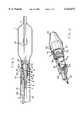
- FIG. 1is a side cross-sectional view of the tip of a catheter illustrating the electronics body, the transducer assembly, and the balloon section of a balloon angioplasty ultrasound imaging catheter embodying the present invention
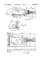
- FIG. 2is a perspective view of the tip of a partially constructed diagnostic imaging catheter prior to joining the signal paths between the separated electronics body and transducer assembly;
- FIG. 3is a detailed side cross-sectional view of the tip of the imaging device portion of the catheter showing the composition of the imaging device;
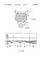
- FIG. 4is a cross-sectional view of the transducer assembly taken along line 4--4 in FIG. 1;
- FIGS. 5a and 5billustratively depict an alternative embodiment of the ultrasound catheter wherein the conducting electrodes in the transducer assembly extend beyond the backing material and the transducer material;
- FIG. 6is a side cross-sectional view of the tip of a catheter illustrating the electronics body, transducer assembly, and nose assembly of an ultrasound diagnostic imaging catheter embodying the present invention
- FIGS. 7a and 7bshow cross-sectional and side-sectional views of an alternative embodiment of the present invention wherein the transducer array is configured to provide a "side-looking" view;
- FIGS. 8a, 8b and 8cshow side, forward, and top cross-sectional views of an alternative embodiment of the present invention wherein the transducer array is configured to provide a "forward-looking" view.
- the inventionwill be described in connection with a catheter used for angioplasty, it will be understood that it is not intended to be limited to such use. On the contrary, the invention is intended to cover all applications which may require imaging in a small cavity.
- An example of such an alternativewould be the use of the present invention on a catheter without the balloon. In such a case, the catheter acts as a diagnostic or monitoring device.
- Another specific alternative use of the present inventionis for measuring blood flow rates using Doppler sound imaging in conjunction with the present invention.
- the present inventionmay also be used to produce internal images of a number of ducts within a body such as the monitoring of gall stones in the bile ducts and for examination and treatment in the area of urology and gynecology.
- Another example of an application of the present inventionis the use of the ultrasound catheter for providing an image of a vessel or duct during application of laser treatment or during the removal of plaque from the walls of a vessel during an antherectomy procedure.
- the present inventionconcerns the structure of the carrier/backing material for the electronics body and transducer assembly and changes to the physical layers of the transducer assembly
- the inventionis intended to be incorporated in general into an ultrasound catheter imaging system of the type described in Proudian, deceased et al. U.S. Pat. No. 4,917,097 the teachings of which are incorporated herein by reference.
- the present ultrasound cathetermay be used to obtain images using a number of different imaging techniques including, for example, the imaging technique described in O'Donnell et al. U.S. application Ser. No. 08/234,848, filed Apr. 28, 1994 (issue fee paid), the teachings of which are expressly incorporated herein by reference.
- FIG. 1A cross-sectional view of a catheter embodying the present invention is illustratively depicted in FIG. 1.
- the catheter shown in FIG. 1 carrying a balloon 1is of the type which is generally used for angioplasty; however, the invention can be used in conjunction with a number of catheter designs such as those illustratively depicted in FIGS. 6, 7 and 8 to provide diagnostic images and deliver treatment to small cavities of the body.
- Conventional guide wire lumens 2 and 3are telescopically fitted over a mating radiopaque guide wire lumen 4 forming a central bore 6 for a catheter guide wire during a normal catheterization procedure.
- An encapsulant 8composed of an epoxy material secures an imaging device 10 comprising the electronics body 12 and the transducer assembly 14 to the end of a catheter shaft 16.
- the imaging device 10in accordance with the present invention contains a multi-sectioned body comprising separate and distinct materials for a carrier 20 and a transducer backing material 24.
- the encapsulant 8protects and insulates a set of integrated circuits (IC's) 18 mounted upon the carrier 20.
- IC'sintegrated circuits
- the imaging device 10is positioned within a proximal sleeve 19 of the balloon 1.
- the transducer assembly 14, described hereinafter in greater detail in conjunction with FIG. 3,generally comprises a set of transducer elements 22.
- the transducer elements 22are supported in a cylindrical shape about the backing material 24.
- other transducer element configurationswill be known to those skilled in the area of transducer devices in view of the present description and in view of the state of the art.
- the balloon 1is positioned adjacent the imaging device 10 and is isolated from ambient conditions by sealing the two ends of the balloon 1 to the catheter shaft 16 and the lumen 3 in a conventional manner.
- a tube 26is embedded within the encapsulant 8 for communicating a fluid between the balloon 1 and an inflation source.
- a radiopaque marker band 27is within the expandable portion of the balloon 1 and attached to the lumen 3 to assist in locating the position of the catheter on a fluoroscope.
- a cable 28comprising an inner and outer set of wires carries electronic data and control signals between the IC's 18 and a control station computer.
- Each inner wire in the cable 28is formed from a solid conductor protected by an insulating coating.
- the outer wiresare spiraled a number of times around the cable 28 in order to shield the signals carried by the inner wires of the cable 28.
- the cableis coated with an insulating material.
- FIG. 2a perspective view is provided of the tip of a partially constructed diagnostic imaging catheter 10 prior to joining the signal paths between the separated electronics body 12 and transducer assembly 14 in order to show the distinct first and second portions of the imaging device 10 comprising the transducer assembly 14 and the electronics body 12.
- the proximal sleeve 19 and the epoxy encapsulant 8 covering the imaging device 10have been removed to expose the integrated circuit chips 18 and associated electronic constructions.
- a nose cone 25provides a blunted lead surface for the ultrasound imaging catheter in order to prevent damage to a vessel as the catheter is guided through the vessel.
- the radiopaque guide wire lumen 4aids in the positioning of the catheter.
- the radiopaque guide wire lumen 4also holds both the electronics body 12 and the transducer assembly 14.
- the outer diameter of the radiopaque guide wire lumen 4is approximately 0.5 millimeters.
- the radiopaque guide wire lumen 4provides the additional function of acting as a guide for precisely positioning the electronics body 12 and transducer assembly 14 in order to mate a set of 64 conductor lines 30 from the IC's 18 mounted upon the electronics body 12 to a set of 64 transducer contacts 32 of the transducer assembly 14 in a manner shown in FIG. 3.
- the gap between the radiopaque guide wire lumen 4 and both the carrier 20 and the backing material 24must be very small and should not be greater than approximately 25 ⁇ m. This minimized gap ensures proper radial alignment of the conductor lines 30 and transducer contacts 32.
- the four IC's 18are of an inverted chip design known to those skilled in the area of the semiconductor chip fabrication art and are bonded to a set of conductive pads 34 formed on the carrier 20.
- the conductive pads 34interconnect the IC's 18 to their neighboring chips and provide a connection between the IC's 18 and the cable 28 that communicatively couples the IC's 18 to a signal processor located outside the patient.
- the padsalso connect the IC's 18 to the conductor lines 30.
- the conductor lines 30link the IC's 18 to a set of 64 electrodes that define the transducer elements in the transducer assembly 14.
- Each of the IC's 18has 16 channels associated with 16 transducer elements defined by 16 transducer electrodes in the transducer assembly 14. Each of the four IC's 18 is responsible for sequentially transmitting and receiving electrical signals in the ultrasonic frequency range on one or more of its 16 channels linked by conductor lines 30 to an associated transducer element in the transducer assembly 14.
- the four IC's 18provide a multiplexing function that distributes excitation pulses from a signal processor to one or more of the transducer elements. At any given time one or more of the 16 channels on each of the IC's 18 is free to be excited by an excitation signal or to receive reflections or echoes by means of activation control signals stored on the IC's 18.
- the electrical signals generated from the reflections impinging on the active transducer elementsare amplified and sent via the transmission cable line 28 to the external signal processor.
- FIG. 3a detailed side cross-sectional view of the imaging portion of the catheter of FIG. 1 is illustrated to show the structure and materials of the imaging device 10.
- the electronics body 12 and the transducer assembly 14are shown in their mated state as they would exist in the final construction of the imaging catheter.
- the layers of the transducer assemblyare shown in detail in FIG. 3 it will be helpful to refer to FIG. 4, a cross section view of the transducer assembly taken along line 4--4 of FIG. 2, during the description of the ringed layers of the transducer assembly 14.
- the carrier 20is bonded to the radiopaque guide wire lumen 4 by means of a glue layer 36 comprising any commercially available medical grade cyanoacrylate epoxy.
- a glue layer 36comprising any commercially available medical grade cyanoacrylate epoxy.
- Onemay substitute any material or structure that satisfactorily immobilizes the electronics body 12 for the glue layer 36.
- the space between the radiopaque guide wire lumen 4 and the carrier 20 filled by the glue layer 36must be very small in order for the radiopaque guide wire lumen 4 to assist in the matching of the electrical contacts between the electronics body 12 and the transducer assembly 14.
- the carrier 20 in the preferred embodiment of the inventionis formed from a rigid, strong material having a low thermal expansion coefficient.
- the carrier 20must be capable of withstanding temperatures in excess of 200 degrees Celsius to which the electronics body 12 is subjected during the process of bonding the set of IC's 18 to the carrier 20. Furthermore, during operation of the ultrasound catheter, self-heating of the IC's 18 may cause expansion of the carrier 20. If the thermal expansion of the carrier 20 is too great, shear forces exerted by the carrier 20 upon the conductive pads 34 create a substantial risk of failure of the electrical connection between the contacts of the IC's 18 and the conductor lines 30.
- Aluminum oxide(Al 2 O 3 ) possesses the aforementioned desired characteristics for the carrier 20; however, other suitable substitutes for this material are well known to those skilled in the art of hybrid circuits.
- Aluminum oxideis also characterized by a very high acoustic impedance (approximately 40 MRayls) and relatively low loss. As will be explained below, these acoustical properties make Aluminum oxide a poor candidate for use as the transducer backing material for applications involving highly sensitive transducer elements.
- An encapsulant 8is applied to the outer surface of the electronics body 12 in order to provide a more cylindrical shape to the catheter assembly and to insulate the electronic circuitry.
- the encapsulant 8generally comprises any commercially available medical grade UV-curable acrylic.
- the outside of the electronics bodymay be covered by a protective layer.
- the protective layeris made of, for example, parylene. Other suitable materials for the protective layer will be known to those skilled in the art of ultrasound catheters or other medical instruments which are inserted within the body.
- the protective layerconsists of the proximal sleeve 19 in the balloon angioplasty catheter shown in FIG. 1 or a sheath 38 in the case of a diagnostic imaging catheter such as the one illustrated in FIG. 6.
- the backing material 24 for the transducer assembly 14is preferably formed from a material characterized by a relatively low acoustic impedance ( ⁇ 10 MRayls) and high loss coefficient (on the order of 20 to 40 dB/mm). This is necessitated by the use of highly sensitive transducer materials such as the PZT composites used for a transducer material 40 whose superior signal sensitivity is otherwise negated by the ringing effect caused by a backing material having a high acoustic impedance and low loss. For this reason, Aluminum oxide is not a preferred material for the backing material 24 for the transducer assembly 14.
- a separate and different materialis used to form the backing material 24 for the ultrasound catheter of the present invention.
- a preferred material for the backing material 24is an epoxy resin filled with either rubber particles or glass microspheres.
- An example of such a resinis "light-weld" 183-M by Dymax Corp., Torrington, Connecticut.
- Other suitable materials having low acoustic impedance and high losswill be known to those of ordinary skill in the art of ultrasound imaging.
- airis an ideal backing material, transducer assemblies using an air backing are difficult to achieve in practice.
- the ultrasound catheter of the present inventionis characterized by an imaging device 10 having separate and distinct carrier/backing materials that exhibit greatly contrasting characteristics.
- the two distinct materialsprovide desirable structural and acoustical characteristics for satisfying the dissimilar requirements for the electronics body 12 and the transducer assembly 14.
- the outer layers of the transducer assembly 14are separately manufactured as a planar sheet. They comprise a first set of 64 conducting electrodes 42, the transducer material 40, a continuous layer conducting electrode 44, and a matching layer 46. After the layers are fabricated, the planar sheet of transducer elements 22 is wrapped around the backing material 24 and bonded by means of a glue layer 48. Depending on the mechanical and acoustic properties of the transducer assembly 14, physical isolation of the transducer elements 22 from one another may be desirable.
- the outer diameter of the backing material 24must be manufactured within very close tolerances so that the ends of the planar sheet of transducer elements, when joined to form a cylinder around the backing material 24, meet with minimal gap or overlap.
- the planar transducer assembly 14may be formed into a cylinder of exact outer diameter concentrically around the radiopaque lumen 4 and the gap between the lumen 4 and the transducer assembly 14 is filled with the backing material 24. This ensures that the spacing between the transducer array elements at the opposite ends of the cylindrically wrapped planar sheet have the same spacing as the other transducer array elements.
- the error in the circumference of the transducer sheet, when wrapped around the lumen 4,should be less than (plus or minus) 8 ⁇ m.
- the inner diameter of the backing material 24must closely match the outer diameter of the radiopaque guide wire lumen 4 in order to facilitate the mating of electrical contacts between the electronics body 12 and the transducer assembly 14.
- the concentric rings comprising the afore-described layers of the transducer assembly 14are illustratively depicted in FIG. 4 showing a cross-sectional view of the transducer assembly taken on line 4--4 of FIG. 1.
- An advantage of the planar sheet transducer element fabrication methodis the absence of capacitive glue layers previously present between the transducer material 40 and each of the conducting electrodes 42 and 44. If the capacitive glue layer remained in the presently described ultrasound catheter, an increased capacitance attributable to the higher dielectric constant of the PZT composite transducer material 40 would negate the improved signal sensitivity of the preferred transducer material.
- the capability of fabricating the transducer material 40 as individual elementsis an important factor when choosing a particular fabrication method in view of the desirability of low cross-talk (less than -30dB), which may necessitate such a separation of elements.
- Some of the possible manufacturers of the planar sheets comprising the transducer elementsare: Precision Acoustic Devices, Fremont, Calif.; Acoustic Imaging, Phoenix, Ariz.; Echo Ultrasound, Lewistown, Pa.; Vermon S.A., Tours, France; and Imasonic, Besancon, France.
- the transducer materialmay be polarized by means of a high voltage on the order of 5,000 Volts applied between the first set of conducting electrodes 42 and the continuous conducting electrode 44. Therefore, it is desirable to perform the polarization procedure on a separated assembly to isolate the transducer assembly 14 from the electronics body 12 since application of such a high voltage to the IC's 18 would destroy the electronic circuitry of the IC's 18.
- the layer of glue 48bonds the backing material 24 to the first set of conducting electrodes 42 spaced evenly about the circumference of the backing material 24.
- the first set of conducting electrodes 42defines the individual transducer elements in the transducer array.
- the first set of conducting electrodes 42is attached to the set of 64 transducer contacts 32.
- Connection material 50electrically couples each one of the transducer contacts 32, corresponding to a single transducer element, to a corresponding one of the conductor lines 30, thereby providing an electronic signal path between the transducer elements 22 and the IC's 18.
- the connection materialcomprises any of several known suitable conductors such as silver or gold loaded epoxy droplets, solder or gold bumps, or solder tape.
- FIGS. 5A and 5Billustratively depict an alternative embodiment of the ultrasound catheter wherein copper conducting electrodes 42 of the transducer assembly 14 extend beyond the backing material 24 and the transducer material 40.
- the portion of the conducting electrodes 42 extending beyond the backing material 24 and overlapping the conductor lines 30 when the transducer assembly 14 is joined to the electronics body 12facilitates the use of a well known gap welder to fuse the individual conductor lines 30 to the corresponding conducting electrodes 42.
- FIG. 5Ashows a cross-sectional view of a partially constructed ultrasound catheter to show the above described connection scheme.
- the use of a gap weldereliminates the need to deposit individual drops of solder material 50 as shown in FIG. 3.
- the elimination of solder dropletspotentially simplifies the design of the electronics carrier 20 that may otherwise require scalloping of the carrier at the end proximate the transducer assembly 14 in order to facilitate proper deposition of the droplets to fuse the conductor lines 30 and the transducer contacts 32.
- Other advantages of this connection schemeinclude better bonding of the conductors, simpler assembly techniques, and enhanced mechanical stability.
- connection scheme portrayed in FIGS. 5A and 5Bis the potential to automate the process of bonding the conducting electrodes 42 to the conductor lines 30.
- the conductor lines 30are matched to the conducting electrodes 42.
- a tip 70 of a gap welderis placed above one of the matched lines.
- the tip 70presses a conducting electrode 42a to a corresponding conductor line 30a.
- a low voltage, high electrical currentpasses between the electrodes of the tip 70.
- the electrical currentfuses the conducting electrode 42a to the conductor line 30a.
- the catheter assemblyis rotated so that a next matched set of lines (42b and 30b) is below the tip 70 and the welding process is repeated. The welding continues until all the lines have been fused.
- the efficiency rating of the transducer materialis high (greater than 50%); the bandwidth should be high (greater than 50% of center frequency); there should be good matching among the transducer elements; there should be low insertion loss (less than -40dB); and the center frequency should be around 20 MHz. Therefore, in the preferred embodiment of the present invention, the transducer material 24 is any one of many known suitable PZT composites.
- the radial thickness of the transducer layer 40is preferably one-half wavelength thickness or an odd multiple of half wavelengths of the intended center operating frequency of the ultrasound catheter. As explained in Biomedical Ultrasonics, at page 53, this enables the transducer to resonate at the center operating frequency of the ultrasound catheter. In the present embodiment, the radial thickness of the transducer material 24 is approximately 0.1 millimeters.
- the backing material 24In order to take advantage of the superior signal sensitivity of transducers formed from PZT composites, the backing material 24 must have a low acoustic impedance. Therefore, the aluminum oxide carrier 20 having a high acoustic impedance should not be used as the backing material 24. Instead the previous monolithic carrier for both the electronics body 12 and the transducer assembly 14 is replaced by the separated carrier/backing sections 20 and 24.
- the continuous conducting electrode 44 covering the outer surface of the transducer material 40is the ground plane for the transducer elements 22. It is preferably a layer of gold metal deposited upon the surface of the matching layer 46 by means of sputtering. However, other suitable conductors and methods to deposit the conductor will be known to those skilled in the art of transducers fabrication. Though not essential to the proper operation of the ultrasound catheter, it is preferred to connect in a known manner the continuous conducting electrode 44 to a ground line provided by the cable 28. The ground line runs along the electronics carrier 20 and is connected to the continuous conducting electrode after the electronics body 12 and the transducer assembly 14 have been joined. One possible way to connect the ground wire is shown in FIG. 2 of the Proudian, deceased et al. U.S. Pat. No. 4,917,097.
- the transducer elements 22are enclosed by a matching layer 46.
- a matching layer 46As explained in Biomedical Ultrasonics, by P.N.T. Wells, Academic Press 1977, at page 54, the efficiency of transmission into the load may be increased by an impedance matching layer of quarter wavelength thickness.
- the matching layer 46comprises a loaded epoxy and is approximately 0.06 mm. thick.
- Alternative appropriate matching layer materials and their thicknesseswill be apparent to those of ordinary skill in the art of ultrasonic imaging.
- the electronics body 12 and the transducer assembly 14are bonded together by a layer of glue 52 and the electrical connections between the electronics body 12 and the transducer assembly 14 are electrically coupled in a manner previously described.
- the cable 28 containing the leads from the signal processor for the ultrasound catheter(previously described in the Proudian et al. '097 patent) are bonded to the conductive pads 34 on the carrier 20 in a known manner.
- FIG. 6shows an alternative embodiment of the present invention, wherein the imaging device 10 is included in a diagnostic imaging catheter that does not contain a balloon 1. Portions of the diagnostic imaging catheter have been removed to reveal the cable 28 and the lumen 2. Since there is no balloon 1 in the imaging catheter shown in FIG. 6, there is of course no tube 26 for filling and draining a fluid from the balloon. Instead, the catheter is fitted with a nose cone 25. The nose cone 25 provides a blunted lead surface for the ultrasound imaging catheter in order to prevent damage to the walls of a cavity as the catheter is inserted. A sheath 38 covers the epoxy resin 8 thereby guarding against contamination of a patient's blood and possibly electrical shock.
- the sheath 38is preferably constructed of parylene, though other suitable substitutes will be known to those skilled in the art of medical instruments that are inserted within a body.
- the structure of the imaging catheter shown in FIG. 6is otherwise unchanged from the structure of the balloon angioplasty ultrasound imaging catheter illustrated in FIG. 1.
- transducer arrayconfigured as a cylinder about a cylindrical core
- FIGS. 7 and 8Examples of such configurations are shown in FIGS. 7 and 8.
- Other configurations of transducer arrays for an ultrasound catheterwill be known to those skilled in the art in view of the present description of this invention.
- FIGS. 7A and 7Billustrate side and cross-sectional views of a side-looking linear array imaging catheter.
- the transducer elements 22are arranged in a plane and perpendicular to the direction of insertion of the imaging catheter. This arrangement provides an image along the length of a cavity.
- the IC's 18are connected to the cable 28 in the same manner as the previously described embodiments of the invention.
- the IC's 18are mounted upon an electronics carrier 20 of the type previously described in connection with the preferred embodiment of the invention shown in FIG. 1.
- the IC'sare electrically coupled to the transducer elements 22 by conductor lines 30.
- the backing material for the transducer elements 22forms the encapsulant 8 in this case.
- FIGS. 8A, 8B and 8Cillustrate side, forward, and top cross-sectional views of a forward-looking "endfire" imaging catheter shown in FIG. 1.
- the encapsulant 8which is also the backing material for the transducers 22, has been partially removed to reveal the placement and orientation of the electronics portion.
- the transducer elements 22are arranged as a planar array mounted upon the leading face of the catheter.
- the guide wire lumen 4is mounted adjacent the ultrasonic imaging device. The diameter of the guide wire lumen 4 is approximately 0.3 mm or about one-third the diameter of the imaging catheter.
- This arrangementprovides a forward looking view of a cavity.
- the dimensions of the field of vieware determined by the size of the array, the number of elements, the element dimensions and frequency.
- the IC's 18are connected to the cable 28 in the same manner as the previously described embodiments of the invention.
- the IC's 18are mounted upon a carrier 20 of the type previously described in connection with the preferred embodiment of the invention shown in FIG. 1.
- the IC'sare electrically coupled to the transducer elements 22 by conductor lines 30.
- the encapsulant 8may form the backing material for the transducer elements 22.
Landscapes
- Health & Medical Sciences (AREA)
- Engineering & Computer Science (AREA)
- Physics & Mathematics (AREA)
- Life Sciences & Earth Sciences (AREA)
- Radar, Positioning & Navigation (AREA)
- Remote Sensing (AREA)
- Acoustics & Sound (AREA)
- Molecular Biology (AREA)
- Heart & Thoracic Surgery (AREA)
- Veterinary Medicine (AREA)
- Public Health (AREA)
- Biophysics (AREA)
- Nuclear Medicine, Radiotherapy & Molecular Imaging (AREA)
- Pathology (AREA)
- Radiology & Medical Imaging (AREA)
- Biomedical Technology (AREA)
- General Health & Medical Sciences (AREA)
- Medical Informatics (AREA)
- Animal Behavior & Ethology (AREA)
- Surgery (AREA)
- Computer Networks & Wireless Communication (AREA)
- General Physics & Mathematics (AREA)
- Gynecology & Obstetrics (AREA)
- Mechanical Engineering (AREA)
- Multimedia (AREA)
- Hematology (AREA)
- Ultra Sonic Daignosis Equipment (AREA)
Abstract
Description
Claims (16)
Priority Applications (5)
| Application Number | Priority Date | Filing Date | Title |
|---|---|---|---|
| US09/324,692US6123673A (en) | 1993-02-01 | 1999-06-02 | Method of making an ultrasound transducer assembly |
| US09/658,323US6283920B1 (en) | 1993-02-01 | 2000-09-08 | Ultrasound transducer assembly |
| US09/906,302US6962567B2 (en) | 1993-02-01 | 2001-07-16 | Ultrasound transducer assembly |
| US11/221,165US20060058681A1 (en) | 1993-02-01 | 2005-09-07 | Ultrasound transducer assembly |
| US11/431,129US20070016071A1 (en) | 1993-02-01 | 2006-05-09 | Ultrasound transducer assembly |
Applications Claiming Priority (6)
| Application Number | Priority Date | Filing Date | Title |
|---|---|---|---|
| US08/012,251US5368037A (en) | 1993-02-01 | 1993-02-01 | Ultrasound catheter |
| US08/234,848US5453575A (en) | 1993-02-01 | 1994-04-28 | Apparatus and method for detecting blood flow in intravascular ultrasonic imaging |
| US08/516,538US5603327A (en) | 1993-02-01 | 1995-08-18 | Ultrasound catheter probe |
| US08/712,166US5779644A (en) | 1993-02-01 | 1996-09-11 | Ultrasound catheter probe |
| US08/935,930US5938615A (en) | 1993-02-01 | 1997-09-23 | Ultrasound catheter probe |
| US09/324,692US6123673A (en) | 1993-02-01 | 1999-06-02 | Method of making an ultrasound transducer assembly |
Related Parent Applications (1)
| Application Number | Title | Priority Date | Filing Date |
|---|---|---|---|
| US08/935,930ContinuationUS5938615A (en) | 1993-02-01 | 1997-09-23 | Ultrasound catheter probe |
Related Child Applications (1)
| Application Number | Title | Priority Date | Filing Date |
|---|---|---|---|
| US09/658,323ContinuationUS6283920B1 (en) | 1993-02-01 | 2000-09-08 | Ultrasound transducer assembly |
Publications (1)
| Publication Number | Publication Date |
|---|---|
| US6123673Atrue US6123673A (en) | 2000-09-26 |
Family
ID=22883065
Family Applications (8)
| Application Number | Title | Priority Date | Filing Date |
|---|---|---|---|
| US08/234,848Expired - LifetimeUS5453575A (en) | 1993-02-01 | 1994-04-28 | Apparatus and method for detecting blood flow in intravascular ultrasonic imaging |
| US08/516,538Expired - LifetimeUS5603327A (en) | 1993-02-01 | 1995-08-18 | Ultrasound catheter probe |
| US08/712,166Expired - LifetimeUS5779644A (en) | 1993-02-01 | 1996-09-11 | Ultrasound catheter probe |
| US08/935,930Expired - LifetimeUS5938615A (en) | 1993-02-01 | 1997-09-23 | Ultrasound catheter probe |
| US09/324,692Expired - LifetimeUS6123673A (en) | 1993-02-01 | 1999-06-02 | Method of making an ultrasound transducer assembly |
| US09/658,323Expired - LifetimeUS6283920B1 (en) | 1993-02-01 | 2000-09-08 | Ultrasound transducer assembly |
| US09/906,302Expired - Fee RelatedUS6962567B2 (en) | 1993-02-01 | 2001-07-16 | Ultrasound transducer assembly |
| US11/221,165AbandonedUS20060058681A1 (en) | 1993-02-01 | 2005-09-07 | Ultrasound transducer assembly |
Family Applications Before (4)
| Application Number | Title | Priority Date | Filing Date |
|---|---|---|---|
| US08/234,848Expired - LifetimeUS5453575A (en) | 1993-02-01 | 1994-04-28 | Apparatus and method for detecting blood flow in intravascular ultrasonic imaging |
| US08/516,538Expired - LifetimeUS5603327A (en) | 1993-02-01 | 1995-08-18 | Ultrasound catheter probe |
| US08/712,166Expired - LifetimeUS5779644A (en) | 1993-02-01 | 1996-09-11 | Ultrasound catheter probe |
| US08/935,930Expired - LifetimeUS5938615A (en) | 1993-02-01 | 1997-09-23 | Ultrasound catheter probe |
Family Applications After (3)
| Application Number | Title | Priority Date | Filing Date |
|---|---|---|---|
| US09/658,323Expired - LifetimeUS6283920B1 (en) | 1993-02-01 | 2000-09-08 | Ultrasound transducer assembly |
| US09/906,302Expired - Fee RelatedUS6962567B2 (en) | 1993-02-01 | 2001-07-16 | Ultrasound transducer assembly |
| US11/221,165AbandonedUS20060058681A1 (en) | 1993-02-01 | 2005-09-07 | Ultrasound transducer assembly |
Country Status (6)
| Country | Link |
|---|---|
| US (8) | US5453575A (en) |
| EP (1) | EP0707453B1 (en) |
| JP (1) | JP3188470B2 (en) |
| CA (1) | CA2163213C (en) |
| DE (1) | DE69533183T2 (en) |
| WO (1) | WO1995029633A1 (en) |
Cited By (73)
| Publication number | Priority date | Publication date | Assignee | Title |
|---|---|---|---|---|
| US6551247B2 (en)* | 2000-03-07 | 2003-04-22 | Matsushita Electric Industrial Co., Ltd. | Ultrasonic probe |
| US6609430B1 (en)* | 2000-05-09 | 2003-08-26 | Shrinivas G. Joshi | Low profile transducer for flow meters |
| US20040054287A1 (en)* | 2002-08-29 | 2004-03-18 | Stephens Douglas Neil | Ultrasonic imaging devices and methods of fabrication |
| US20040067000A1 (en)* | 2002-10-07 | 2004-04-08 | Bates Kenneth N. | Systems and methods for minimally-invasive optical-acoustic imaging |
| US20040082844A1 (en)* | 1998-03-05 | 2004-04-29 | Vardi Gil M. | Optical-acoustic imaging device |
| US6962567B2 (en)* | 1993-02-01 | 2005-11-08 | Volcano Therapeutics, Inc. | Ultrasound transducer assembly |
| US20060066184A1 (en)* | 2003-04-01 | 2006-03-30 | Olympus Corporation | Ultrasonic transducer and manufacturing method thereof |
| US20070116408A1 (en)* | 2005-11-22 | 2007-05-24 | Eberle Michael J | Optical imaging probe connector |
| US20070163710A1 (en)* | 2005-12-23 | 2007-07-19 | 3M Innovative Properties Company | Fluorochemical ketone compounds and processes for their use |
| US20090261690A1 (en)* | 2006-09-25 | 2009-10-22 | Tomoaki Mashimo | Ultrasonic wave handling device and a microscopic in-tube inspection system |
| US20100087732A1 (en)* | 2008-10-02 | 2010-04-08 | Vascular Imaging Corporation | Optical ultrasound receiver |
| US7830069B2 (en) | 2004-04-20 | 2010-11-09 | Sunnybrook Health Sciences Centre | Arrayed ultrasonic transducer |
| US7901358B2 (en) | 2005-11-02 | 2011-03-08 | Visualsonics Inc. | High frequency array ultrasound system |
| US8316518B2 (en) | 2008-09-18 | 2012-11-27 | Visualsonics Inc. | Methods for manufacturing ultrasound transducers and other components |
| WO2015116944A1 (en) | 2014-01-30 | 2015-08-06 | Volcano Corporation | Devices and methods for treating fistulas |
| US9173047B2 (en) | 2008-09-18 | 2015-10-27 | Fujifilm Sonosite, Inc. | Methods for manufacturing ultrasound transducers and other components |
| US9184369B2 (en) | 2008-09-18 | 2015-11-10 | Fujifilm Sonosite, Inc. | Methods for manufacturing ultrasound transducers and other components |
| US9286673B2 (en) | 2012-10-05 | 2016-03-15 | Volcano Corporation | Systems for correcting distortions in a medical image and methods of use thereof |
| US9292918B2 (en) | 2012-10-05 | 2016-03-22 | Volcano Corporation | Methods and systems for transforming luminal images |
| US9295447B2 (en) | 2011-08-17 | 2016-03-29 | Volcano Corporation | Systems and methods for identifying vascular borders |
| US9301687B2 (en) | 2013-03-13 | 2016-04-05 | Volcano Corporation | System and method for OCT depth calibration |
| US9307926B2 (en) | 2012-10-05 | 2016-04-12 | Volcano Corporation | Automatic stent detection |
| US9324141B2 (en) | 2012-10-05 | 2016-04-26 | Volcano Corporation | Removal of A-scan streaking artifact |
| US9360630B2 (en) | 2011-08-31 | 2016-06-07 | Volcano Corporation | Optical-electrical rotary joint and methods of use |
| US9367965B2 (en) | 2012-10-05 | 2016-06-14 | Volcano Corporation | Systems and methods for generating images of tissue |
| US9383263B2 (en) | 2012-12-21 | 2016-07-05 | Volcano Corporation | Systems and methods for narrowing a wavelength emission of light |
| US9478940B2 (en) | 2012-10-05 | 2016-10-25 | Volcano Corporation | Systems and methods for amplifying light |
| US9486143B2 (en) | 2012-12-21 | 2016-11-08 | Volcano Corporation | Intravascular forward imaging device |
| US9596993B2 (en) | 2007-07-12 | 2017-03-21 | Volcano Corporation | Automatic calibration systems and methods of use |
| US9612105B2 (en) | 2012-12-21 | 2017-04-04 | Volcano Corporation | Polarization sensitive optical coherence tomography system |
| US9622706B2 (en) | 2007-07-12 | 2017-04-18 | Volcano Corporation | Catheter for in vivo imaging |
| US9709379B2 (en) | 2012-12-20 | 2017-07-18 | Volcano Corporation | Optical coherence tomography system that is reconfigurable between different imaging modes |
| US9730613B2 (en) | 2012-12-20 | 2017-08-15 | Volcano Corporation | Locating intravascular images |
| US9770172B2 (en) | 2013-03-07 | 2017-09-26 | Volcano Corporation | Multimodal segmentation in intravascular images |
| WO2017198800A1 (en) | 2016-05-20 | 2017-11-23 | Koninklijke Philips N.V. | Devices and methods for stratification of patients for renal denervation based on intravascular pressure and cross-sectional lumen measurements |
| US9858668B2 (en) | 2012-10-05 | 2018-01-02 | Volcano Corporation | Guidewire artifact removal in images |
| US9867530B2 (en) | 2006-08-14 | 2018-01-16 | Volcano Corporation | Telescopic side port catheter device with imaging system and method for accessing side branch occlusions |
| US10058284B2 (en) | 2012-12-21 | 2018-08-28 | Volcano Corporation | Simultaneous imaging, monitoring, and therapy |
| US10070827B2 (en) | 2012-10-05 | 2018-09-11 | Volcano Corporation | Automatic image playback |
| US10080491B2 (en) | 2011-12-08 | 2018-09-25 | Volcano Corporation | Devices, systems, and methods for visualizing an occluded vessel |
| US10166003B2 (en) | 2012-12-21 | 2019-01-01 | Volcano Corporation | Ultrasound imaging with variable line density |
| US10191220B2 (en) | 2012-12-21 | 2019-01-29 | Volcano Corporation | Power-efficient optical circuit |
| US10219887B2 (en) | 2013-03-14 | 2019-03-05 | Volcano Corporation | Filters with echogenic characteristics |
| US10219780B2 (en) | 2007-07-12 | 2019-03-05 | Volcano Corporation | OCT-IVUS catheter for concurrent luminal imaging |
| US10226597B2 (en) | 2013-03-07 | 2019-03-12 | Volcano Corporation | Guidewire with centering mechanism |
| US10238367B2 (en) | 2012-12-13 | 2019-03-26 | Volcano Corporation | Devices, systems, and methods for targeted cannulation |
| US10292677B2 (en) | 2013-03-14 | 2019-05-21 | Volcano Corporation | Endoluminal filter having enhanced echogenic properties |
| US10332228B2 (en) | 2012-12-21 | 2019-06-25 | Volcano Corporation | System and method for graphical processing of medical data |
| US10413317B2 (en) | 2012-12-21 | 2019-09-17 | Volcano Corporation | System and method for catheter steering and operation |
| WO2019174984A1 (en) | 2018-03-15 | 2019-09-19 | Koninklijke Philips N.V. | Variable intraluminal ultrasound transmit pulse generation and control devices, systems, and methods |
| US10420530B2 (en) | 2012-12-21 | 2019-09-24 | Volcano Corporation | System and method for multipath processing of image signals |
| US10426590B2 (en) | 2013-03-14 | 2019-10-01 | Volcano Corporation | Filters with echogenic characteristics |
| WO2020002061A1 (en) | 2018-06-27 | 2020-01-02 | Koninklijke Philips N.V. | Dynamic resource reconfiguration for patient interface module (pim) in intraluminal medical ultrasound imaging |
| US10568586B2 (en) | 2012-10-05 | 2020-02-25 | Volcano Corporation | Systems for indicating parameters in an imaging data set and methods of use |
| US10595820B2 (en) | 2012-12-20 | 2020-03-24 | Philips Image Guided Therapy Corporation | Smooth transition catheters |
| WO2020070021A1 (en) | 2018-10-04 | 2020-04-09 | Koninklijke Philips N.V. | Fluid flow detection for ultrasound imaging devices, systems, and methods |
| US10638939B2 (en) | 2013-03-12 | 2020-05-05 | Philips Image Guided Therapy Corporation | Systems and methods for diagnosing coronary microvascular disease |
| US10724082B2 (en) | 2012-10-22 | 2020-07-28 | Bio-Rad Laboratories, Inc. | Methods for analyzing DNA |
| US10758207B2 (en) | 2013-03-13 | 2020-09-01 | Philips Image Guided Therapy Corporation | Systems and methods for producing an image from a rotational intravascular ultrasound device |
| US10942022B2 (en) | 2012-12-20 | 2021-03-09 | Philips Image Guided Therapy Corporation | Manual calibration of imaging system |
| US10939826B2 (en) | 2012-12-20 | 2021-03-09 | Philips Image Guided Therapy Corporation | Aspirating and removing biological material |
| WO2021069216A1 (en) | 2019-10-10 | 2021-04-15 | Koninklijke Philips N.V. | Vascular tissue characterization devices, systems, and methods |
| US10993694B2 (en) | 2012-12-21 | 2021-05-04 | Philips Image Guided Therapy Corporation | Rotational ultrasound imaging catheter with extended catheter body telescope |
| US11026591B2 (en) | 2013-03-13 | 2021-06-08 | Philips Image Guided Therapy Corporation | Intravascular pressure sensor calibration |
| US11040140B2 (en) | 2010-12-31 | 2021-06-22 | Philips Image Guided Therapy Corporation | Deep vein thrombosis therapeutic methods |
| US11141063B2 (en) | 2010-12-23 | 2021-10-12 | Philips Image Guided Therapy Corporation | Integrated system architectures and methods of use |
| US11154313B2 (en) | 2013-03-12 | 2021-10-26 | The Volcano Corporation | Vibrating guidewire torquer and methods of use |
| US11272845B2 (en) | 2012-10-05 | 2022-03-15 | Philips Image Guided Therapy Corporation | System and method for instant and automatic border detection |
| US11406498B2 (en) | 2012-12-20 | 2022-08-09 | Philips Image Guided Therapy Corporation | Implant delivery system and implants |
| US11445998B2 (en) | 2013-03-14 | 2022-09-20 | Philips Image Guided Therapy Corporation | System and method of adventitial tissue characterization |
| US11596469B2 (en) | 2012-12-21 | 2023-03-07 | Philips Image Guided Therapy Corporation | Device, system, and method for imaging and tissue characterization of ablated tissue |
| US12201477B2 (en) | 2012-10-05 | 2025-01-21 | Philips Image Guided Therapy Corporation | Methods and systems for establishing parameters for three-dimensional imaging |
| US12343198B2 (en) | 2013-03-14 | 2025-07-01 | Philips Image Guided Therapy Corporation | Delivery catheter having imaging capabilities |
Families Citing this family (294)
| Publication number | Priority date | Publication date | Assignee | Title |
|---|---|---|---|---|
| GB2301892B (en)* | 1992-07-14 | 1997-02-26 | Intravascular Res Ltd | Methods and apparatus for the examination and treatment of internal organs |
| GB2296565B (en)* | 1994-12-23 | 1999-06-16 | Intravascular Res Ltd | Ultrasound imaging |
| GB2293240B (en)* | 1994-09-15 | 1998-05-20 | Intravascular Res Ltd | Ultrasonic visualisation method and apparatus |
| US6210356B1 (en) | 1998-08-05 | 2001-04-03 | Ekos Corporation | Ultrasound assembly for use with a catheter |
| US6176842B1 (en)* | 1995-03-08 | 2001-01-23 | Ekos Corporation | Ultrasound assembly for use with light activated drugs |
| US6254542B1 (en) | 1995-07-17 | 2001-07-03 | Intravascular Research Limited | Ultrasonic visualization method and apparatus |
| AU6857796A (en) | 1995-08-24 | 1997-03-19 | Interventional Innovations Corporation | X-ray catheter |
| US6377846B1 (en) | 1997-02-21 | 2002-04-23 | Medtronic Ave, Inc. | Device for delivering localized x-ray radiation and method of manufacture |
| US5706819A (en)* | 1995-10-10 | 1998-01-13 | Advanced Technology Laboratories, Inc. | Ultrasonic diagnostic imaging with harmonic contrast agents |
| JPH09103431A (en) | 1995-10-13 | 1997-04-22 | Olympus Optical Co Ltd | Ultrasonic diagnostic device |
| US7226417B1 (en)* | 1995-12-26 | 2007-06-05 | Volcano Corporation | High resolution intravascular ultrasound transducer assembly having a flexible substrate |
| US5724974A (en)* | 1996-03-22 | 1998-03-10 | Acuson Corporation | Two-dimensional ultrasound display system |
| US5916170A (en)* | 1996-09-24 | 1999-06-29 | The Board Of Trustees Of The Leland Stanford Junior University | Method and apparatus for curvature detection in vessels from phase shifts of a plurality of input electrical signals |
| US5824879A (en)* | 1996-10-04 | 1998-10-20 | Rosemount Inc. | Method of calibrating an ultrasonic flow meter |
| US5752518A (en)* | 1996-10-28 | 1998-05-19 | Ep Technologies, Inc. | Systems and methods for visualizing interior regions of the body |
| DE69735927T2 (en)* | 1996-11-26 | 2007-05-24 | ATL Ultrasound, Inc., Bothell | Diagnostic imaging by means of ultrasound of different transmission and reception frequencies |
| US5857974A (en)* | 1997-01-08 | 1999-01-12 | Endosonics Corporation | High resolution intravascular ultrasound transducer assembly having a flexible substrate |
| US5954654A (en)* | 1997-01-31 | 1999-09-21 | Acuson Corporation | Steering mechanism and steering line for a catheter-mounted ultrasonic transducer |
| USD455210S1 (en) | 1997-01-31 | 2002-04-02 | Acuson Corporation | Ultrasonic transducer assembly controller |
| US5938616A (en) | 1997-01-31 | 1999-08-17 | Acuson Corporation | Steering mechanism and steering line for a catheter-mounted ultrasonic transducer |
| EP2264428B1 (en) | 1997-01-31 | 2017-05-03 | Xy, Llc | Optical apparatus with focussing reflector for converging radiation onto a flow of particles |
| US6464645B1 (en) | 1997-01-31 | 2002-10-15 | Acuson Corporation | Ultrasonic transducer assembly controller |
| EP0860181B1 (en)* | 1997-02-21 | 2004-04-28 | Medtronic Ave, Inc. | X-ray device having a dilatation structure for delivering localized radiation to an interior of a body |
| US6309339B1 (en) | 1997-03-28 | 2001-10-30 | Endosonics Corporation | Intravascular radiation delivery device |
| US5800358A (en)* | 1997-03-31 | 1998-09-01 | Hewlett Packard Company | Undersampled omnidirectional ultrasonic flow detector |
| US5921931A (en) | 1997-04-08 | 1999-07-13 | Endosonics Corporation | Method and apparatus for creating a color blood flow image based upon ultrasonic echo signals received by an intravascular ultrasound imaging probe |
| US6676626B1 (en)* | 1998-05-01 | 2004-01-13 | Ekos Corporation | Ultrasound assembly with increased efficacy |
| US6001069A (en)* | 1997-05-01 | 1999-12-14 | Ekos Corporation | Ultrasound catheter for providing a therapeutic effect to a vessel of a body |
| US6723063B1 (en)* | 1998-06-29 | 2004-04-20 | Ekos Corporation | Sheath for use with an ultrasound element |
| US6582392B1 (en)* | 1998-05-01 | 2003-06-24 | Ekos Corporation | Ultrasound assembly for use with a catheter |
| US6095976A (en)* | 1997-06-19 | 2000-08-01 | Medinol Ltd. | Method for enhancing an image derived from reflected ultrasound signals produced by an ultrasound transmitter and detector inserted in a bodily lumen |
| JP3857788B2 (en)* | 1997-09-01 | 2006-12-13 | テルモ株式会社 | Cardiovascular information measurement system |
| US6049159A (en)* | 1997-10-06 | 2000-04-11 | Albatros Technologies, Inc. | Wideband acoustic transducer |
| US6050943A (en) | 1997-10-14 | 2000-04-18 | Guided Therapy Systems, Inc. | Imaging, therapy, and temperature monitoring ultrasonic system |
| US5924993A (en)* | 1997-10-15 | 1999-07-20 | Advanced Coronary Intervention, Inc. | Intravascular ultrasound mixed signal multiplexer/pre-amplifier asic |
| WO1999022644A1 (en)* | 1997-11-03 | 1999-05-14 | Barzell Whitmore Maroon Bells, Inc. | Ultrasound interface control system |
| US5876344A (en)* | 1997-12-09 | 1999-03-02 | Endosonics Corporation | Modular imaging/treatment catheter assembly and method |
| US6149867A (en) | 1997-12-31 | 2000-11-21 | Xy, Inc. | Sheath fluids and collection systems for sex-specific cytometer sorting of sperm |
| US6071689A (en) | 1997-12-31 | 2000-06-06 | Xy, Inc. | System for improving yield of sexed embryos in mammals |
| US6108402A (en)* | 1998-01-16 | 2000-08-22 | Medtronic Ave, Inc. | Diamond vacuum housing for miniature x-ray device |
| USD465024S1 (en) | 1998-01-31 | 2002-10-29 | Acuson Corporation | Ultrasonic transducer assembly controller |
| US6069938A (en)* | 1998-03-06 | 2000-05-30 | Chornenky; Victor Ivan | Method and x-ray device using pulse high voltage source |
| US6074348A (en)* | 1998-03-31 | 2000-06-13 | General Electric Company | Method and apparatus for enhanced flow imaging in B-mode ultrasound |
| US6295680B1 (en)* | 1998-07-05 | 2001-10-02 | The Regents Of The University Of Michigan | Method for detecting early atherosclerosis and vascular damage using radioactive tracers and intravascular radiation detection devices |
| US7772005B1 (en) | 1998-07-30 | 2010-08-10 | Xy, Llc | Method of establishing an equine artificial insemination sample |
| US6036650A (en)* | 1998-09-15 | 2000-03-14 | Endosonics Corporation | Ultrasonic imaging system and method with ringdown reduction |
| US6312402B1 (en) | 1998-09-24 | 2001-11-06 | Ekos Corporation | Ultrasound catheter for improving blood flow to the heart |
| US6126599A (en)* | 1998-10-01 | 2000-10-03 | Atl Ultrasound, Inc. | Ultrasonic diagnostic imaging system with real time spatial compounding processor |
| US6102862A (en) | 1998-10-02 | 2000-08-15 | Scimed Life Systems, Inc. | Adaptive cancellation of ring-down artifact in IVUS imaging |
| DE19922056A1 (en)* | 1999-05-14 | 2000-11-23 | Heinz Lehr | Medical instrument for internal examinations using ultrasonic or electromagnetic transducers, has drive connected to transducer at remote end of instrument so that it can be rotated |
| US6645152B1 (en) | 1999-06-02 | 2003-11-11 | Matthew T. Jung | Apparatus for the intravascular ultrasound-guided placement of a vena cava filter |
| US6440077B1 (en) | 1999-06-02 | 2002-08-27 | Matthew T. Jung | Apparatus and method for the intravascular ultrasound-guided placement of a vena cava filter |
| JP4223629B2 (en) | 1999-06-16 | 2009-02-12 | 日本特殊陶業株式会社 | Transceiver for ultrasonic probe, method for manufacturing the same, and ultrasonic probe using the transducer |
| US6685645B1 (en) | 2001-10-20 | 2004-02-03 | Zonare Medical Systems, Inc. | Broad-beam imaging |
| US6371915B1 (en) | 1999-11-02 | 2002-04-16 | Scimed Life Systems, Inc. | One-twelfth wavelength impedence matching transformer |
| US7208265B1 (en) | 1999-11-24 | 2007-04-24 | Xy, Inc. | Method of cryopreserving selected sperm cells |
| US6457365B1 (en)* | 2000-02-09 | 2002-10-01 | Endosonics Corporation | Method and apparatus for ultrasonic imaging |
| AU5468301A (en) | 2000-03-15 | 2001-09-24 | Boston Scientific Limited | Ablation and imaging catheter |
| ITSV20000018A1 (en)* | 2000-05-05 | 2001-11-05 | Esaote Spa | METHOD AND APPARATUS FOR DETECTION OF ECHOGRAPHIC IMAGES, IN PARTICULAR OF MOVING BODIES OF FLOW OR SIMILAR FABRICS |
| DK2258168T3 (en) | 2000-05-09 | 2019-10-07 | Xy Llc | Apparatus for isolating X-chromosome-bearing and Y-chromosome-bearing populations of spermatozoa |
| AU7046601A (en)* | 2000-05-30 | 2001-12-17 | Patrik Rogalla | Method for the combined representation of morphology and dynamics in split-imageand volume-image methods |
| GB2365127A (en)* | 2000-07-20 | 2002-02-13 | Jomed Imaging Ltd | Catheter |
| US6974416B2 (en) | 2000-08-16 | 2005-12-13 | Cook Vascular Incorporated | Doppler probe with shapeable portion |
| US6416477B1 (en) | 2000-08-22 | 2002-07-09 | Koninklijke Philips Electronics N.V. | Ultrasonic diagnostic systems with spatial compounded panoramic imaging |
| JP4798826B2 (en)* | 2000-08-25 | 2011-10-19 | 古野電気株式会社 | Beam angle control method and control apparatus for cylindrical transducer |
| CA2822983C (en)* | 2000-11-29 | 2017-05-09 | Xy, Llc | System to separate frozen-thawed spermatozoa into x-chromosome bearing and y-chromosome bearing populations |
| US7713687B2 (en) | 2000-11-29 | 2010-05-11 | Xy, Inc. | System to separate frozen-thawed spermatozoa into x-chromosome bearing and y-chromosome bearing populations |
| WO2002043593A1 (en) | 2000-12-01 | 2002-06-06 | The Cleveland Clinic Foundation | Miniature ultrasound transducer |
| GB0030449D0 (en)* | 2000-12-13 | 2001-01-24 | Deltex Guernsey Ltd | Improvements in or relating to doppler haemodynamic monitors |
| US7914453B2 (en) | 2000-12-28 | 2011-03-29 | Ardent Sound, Inc. | Visual imaging system for ultrasonic probe |
| US20030060731A1 (en)* | 2001-01-26 | 2003-03-27 | Fleischhacker Mark G. | Non-metallic guide wire |
| US6589182B1 (en) | 2001-02-12 | 2003-07-08 | Acuson Corporation | Medical diagnostic ultrasound catheter with first and second tip portions |
| US6936009B2 (en)* | 2001-02-27 | 2005-08-30 | General Electric Company | Matching layer having gradient in impedance for ultrasound transducers |
| US7387612B2 (en)* | 2001-03-28 | 2008-06-17 | Cybersonics, Inc. | Floating probe for ultrasonic transducers |
| US6689087B2 (en) | 2001-03-28 | 2004-02-10 | Cybersonics, Inc. | Floating probe for ultrasonic transducers |
| US6866631B2 (en)* | 2001-05-31 | 2005-03-15 | Zonare Medical Systems, Inc. | System for phase inversion ultrasonic imaging |
| US6728571B1 (en)* | 2001-07-16 | 2004-04-27 | Scimed Life Systems, Inc. | Electronically scanned optical coherence tomography with frequency modulated signals |
| US6795732B2 (en) | 2001-10-30 | 2004-09-21 | Medtronic, Inc. | Implantable medical device employing sonomicrometer output signals for detection and measurement of cardiac mechanical function |
| US20040019318A1 (en)* | 2001-11-07 | 2004-01-29 | Wilson Richard R. | Ultrasound assembly for use with a catheter |
| EP1647232B1 (en) | 2001-12-03 | 2011-08-17 | Ekos Corporation | Catheter with multiple ultrasound radiating members |
| US6979293B2 (en)* | 2001-12-14 | 2005-12-27 | Ekos Corporation | Blood flow reestablishment determination |
| US20030125959A1 (en)* | 2001-12-31 | 2003-07-03 | Palmquist Robert D. | Translation device with planar microphone array |
| US20030195415A1 (en)* | 2002-02-14 | 2003-10-16 | Iddan Gavriel J. | Device, system and method for accoustic in-vivo measuring |
| US8226629B1 (en) | 2002-04-01 | 2012-07-24 | Ekos Corporation | Ultrasonic catheter power control |
| US7617005B2 (en)* | 2002-04-08 | 2009-11-10 | Ardian, Inc. | Methods and apparatus for thermally-induced renal neuromodulation |
| EP2284256A3 (en) | 2002-08-01 | 2012-08-29 | Xy, Llc | Low pressure sperm separation system |
| US8486618B2 (en) | 2002-08-01 | 2013-07-16 | Xy, Llc | Heterogeneous inseminate system |
| MXPA05001654A (en) | 2002-08-15 | 2005-10-18 | Xy Inc | High resolution flow cytometer. |
| US6712767B2 (en) | 2002-08-29 | 2004-03-30 | Volcano Therapeutics, Inc. | Ultrasonic imaging devices and methods of fabrication |
| US7169548B2 (en) | 2002-09-13 | 2007-01-30 | Xy, Inc. | Sperm cell processing and preservation systems |
| US20040068190A1 (en)* | 2002-10-04 | 2004-04-08 | Cespedes Eduardo Ignacio | Imaging catheter with indicia and methods of use |
| US6921371B2 (en)* | 2002-10-14 | 2005-07-26 | Ekos Corporation | Ultrasound radiating members for catheter |
| JP2004230033A (en)* | 2003-01-31 | 2004-08-19 | Toshiba Corp | Ultrasonic probe repolarizing device, ultrasonic probe and ultrasonic diagnostic device |
| MX350776B (en) | 2003-03-28 | 2017-09-15 | Inguran Llc * | Apparatus, methods and processes for sorting particles and for providing sex-sorted animal sperm. |
| US7314448B2 (en)* | 2003-03-28 | 2008-01-01 | Scimed Life Systems, Inc. | Imaging transducer assembly |
| NZ544103A (en) | 2003-05-15 | 2010-10-29 | Xy Llc | Efficient haploid cell sorting for flow cytometer systems |
| US8282561B2 (en)* | 2003-05-23 | 2012-10-09 | Arizona Board Of Regents | Piezo micro-markers for ultrasound medical diagnostics |
| US8335555B2 (en) | 2003-05-30 | 2012-12-18 | Lawrence Livermore National Security, Llc | Radial reflection diffraction tomography |
| US20040254471A1 (en)* | 2003-06-13 | 2004-12-16 | Andreas Hadjicostis | Miniature ultrasonic phased array for intracardiac and intracavity applications |
| US6958540B2 (en)* | 2003-06-23 | 2005-10-25 | International Business Machines Corporation | Dual damascene interconnect structures having different materials for line and via conductors |
| US7670335B2 (en)* | 2003-07-21 | 2010-03-02 | Biosense Webster, Inc. | Ablation device with spiral array ultrasound transducer |
| US8147486B2 (en)* | 2003-09-22 | 2012-04-03 | St. Jude Medical, Atrial Fibrillation Division, Inc. | Medical device with flexible printed circuit |
| US7229437B2 (en)* | 2003-09-22 | 2007-06-12 | St. Jude Medical, Atrial Fibrillation Division, Inc. | Medical device having integral traces and formed electrodes |
| US7234225B2 (en)* | 2003-09-22 | 2007-06-26 | St. Jude Medical, Atrial Fibrillation Division, Inc. | Method for manufacturing medical device having embedded traces and formed electrodes |
| US20050251127A1 (en)* | 2003-10-15 | 2005-11-10 | Jared Brosch | Miniature ultrasonic transducer with focusing lens for intracardiac and intracavity applications |
| US7946991B2 (en)* | 2003-10-17 | 2011-05-24 | Panasonic Corporation | Ultrasonic doppler blood flow measuring device |
| US7951081B2 (en) | 2003-10-20 | 2011-05-31 | Boston Scientific Scimed, Inc. | Transducer/sensor assembly |
| US8206304B1 (en)* | 2003-12-16 | 2012-06-26 | Vascular Technology Incorporated | Doppler transceiver and probe for use in minimally invasive procedures |
| US7431698B2 (en) | 2004-01-13 | 2008-10-07 | Ge Medical Systems Global Technology Company, Llc | Apparatus and method for controlling an ultrasound probe |
| US20080051660A1 (en)* | 2004-01-16 | 2008-02-28 | The University Of Houston System | Methods and apparatuses for medical imaging |
| EP1713537A4 (en) | 2004-01-29 | 2009-04-29 | Ekos Corp | Method and apparatus for detecting vascular conditions with a catheter |
| NZ550196A (en) | 2004-03-29 | 2010-11-26 | Inguran Llc | Method for sorting sperm cells into X or Y chromosome-bearing enriched populations comprising a composition which inhibits motility and a DNA-selective dye |
| US20070222339A1 (en)* | 2004-04-20 | 2007-09-27 | Mark Lukacs | Arrayed ultrasonic transducer |
| AU2005266930B2 (en) | 2004-07-22 | 2010-09-16 | Inguran, Llc | Process for enriching a population of sperm cells |
| JP4621452B2 (en)* | 2004-08-20 | 2011-01-26 | 富士フイルム株式会社 | Ultrasound endoscope and ultrasound endoscope apparatus |
| US7672706B2 (en)* | 2004-08-23 | 2010-03-02 | Boston Scientific Scimed, Inc. | Systems and methods for measuring pulse wave velocity with an intravascular device |
| US9011336B2 (en) | 2004-09-16 | 2015-04-21 | Guided Therapy Systems, Llc | Method and system for combined energy therapy profile |
| US7824348B2 (en) | 2004-09-16 | 2010-11-02 | Guided Therapy Systems, L.L.C. | System and method for variable depth ultrasound treatment |
| US7393325B2 (en) | 2004-09-16 | 2008-07-01 | Guided Therapy Systems, L.L.C. | Method and system for ultrasound treatment with a multi-directional transducer |
| US8535228B2 (en) | 2004-10-06 | 2013-09-17 | Guided Therapy Systems, Llc | Method and system for noninvasive face lifts and deep tissue tightening |
| US8444562B2 (en) | 2004-10-06 | 2013-05-21 | Guided Therapy Systems, Llc | System and method for treating muscle, tendon, ligament and cartilage tissue |
| US10864385B2 (en) | 2004-09-24 | 2020-12-15 | Guided Therapy Systems, Llc | Rejuvenating skin by heating tissue for cosmetic treatment of the face and body |
| US20120165848A1 (en) | 2010-08-02 | 2012-06-28 | Guided Therapy Systems, Llc | System and method for treating cartilage |
| US9694212B2 (en) | 2004-10-06 | 2017-07-04 | Guided Therapy Systems, Llc | Method and system for ultrasound treatment of skin |
| US20060111744A1 (en) | 2004-10-13 | 2006-05-25 | Guided Therapy Systems, L.L.C. | Method and system for treatment of sweat glands |
| US11883688B2 (en) | 2004-10-06 | 2024-01-30 | Guided Therapy Systems, Llc | Energy based fat reduction |
| US8133180B2 (en) | 2004-10-06 | 2012-03-13 | Guided Therapy Systems, L.L.C. | Method and system for treating cellulite |
| US11235179B2 (en) | 2004-10-06 | 2022-02-01 | Guided Therapy Systems, Llc | Energy based skin gland treatment |
| US8690779B2 (en) | 2004-10-06 | 2014-04-08 | Guided Therapy Systems, Llc | Noninvasive aesthetic treatment for tightening tissue |
| JP5094402B2 (en) | 2004-10-06 | 2012-12-12 | ガイデッド セラピー システムズ, エル.エル.シー. | Method and system for ultrasonic tissue processing |
| US7758524B2 (en) | 2004-10-06 | 2010-07-20 | Guided Therapy Systems, L.L.C. | Method and system for ultra-high frequency ultrasound treatment |
| US9827449B2 (en) | 2004-10-06 | 2017-11-28 | Guided Therapy Systems, L.L.C. | Systems for treating skin laxity |
| JP2008522642A (en) | 2004-10-06 | 2008-07-03 | ガイデッド セラピー システムズ, エル.エル.シー. | Method and system for beauty enhancement |
| US11724133B2 (en) | 2004-10-07 | 2023-08-15 | Guided Therapy Systems, Llc | Ultrasound probe for treatment of skin |
| US11207548B2 (en) | 2004-10-07 | 2021-12-28 | Guided Therapy Systems, L.L.C. | Ultrasound probe for treating skin laxity |
| US20060184070A1 (en)* | 2004-11-12 | 2006-08-17 | Hansmann Douglas R | External ultrasonic therapy |
| US20060173387A1 (en)* | 2004-12-10 | 2006-08-03 | Douglas Hansmann | Externally enhanced ultrasonic therapy |
| US7930014B2 (en) | 2005-01-11 | 2011-04-19 | Volcano Corporation | Vascular image co-registration |
| CA2603495A1 (en)* | 2005-04-01 | 2006-10-12 | Visualsonics Inc. | System and method for 3-d visualization of vascular structures using ultrasound |
| WO2006116480A2 (en) | 2005-04-25 | 2006-11-02 | Guided Therapy Systems, L.L.C. | Method and system for enhancing computer peripheral saftey |
| US20070016056A1 (en)* | 2005-07-15 | 2007-01-18 | Scott Kerwin | Methods and systems for providing control components in an ultrasound system |
| US8446071B2 (en)* | 2005-07-20 | 2013-05-21 | Ust, Inc. | Thermally enhanced ultrasound transducer system |
| US7618770B2 (en) | 2005-07-29 | 2009-11-17 | Xy, Inc. | Methods and apparatus for reducing protein content in sperm cell extenders |
| CN100445488C (en)* | 2005-08-01 | 2008-12-24 | 邱则有 | A cavity component for cast-in-place concrete molding |
| US8784336B2 (en) | 2005-08-24 | 2014-07-22 | C. R. Bard, Inc. | Stylet apparatuses and methods of manufacture |
| JP5443760B2 (en)* | 2005-11-10 | 2014-03-19 | ブラッコ・シュイス・ソシエテ・アノニム | Detection of immobilized contrast agents in medical imaging applications based on rheological analysis |
| US8764664B2 (en) | 2005-11-28 | 2014-07-01 | Vizyontech Imaging, Inc. | Methods and apparatus for conformable medical data acquisition pad and configurable imaging system |
| US20070167826A1 (en)* | 2005-11-30 | 2007-07-19 | Warren Lee | Apparatuses for thermal management of actuated probes, such as catheter distal ends |
| US20070167825A1 (en)* | 2005-11-30 | 2007-07-19 | Warren Lee | Apparatus for catheter tips, including mechanically scanning ultrasound probe catheter tip |
| US20070167824A1 (en)* | 2005-11-30 | 2007-07-19 | Warren Lee | Method of manufacture of catheter tips, including mechanically scanning ultrasound probe catheter tip, and apparatus made by the method |
| US20070167821A1 (en)* | 2005-11-30 | 2007-07-19 | Warren Lee | Rotatable transducer array for volumetric ultrasound |
| US7867169B2 (en)* | 2005-12-02 | 2011-01-11 | Abbott Cardiovascular Systems Inc. | Echogenic needle catheter configured to produce an improved ultrasound image |
| KR100875413B1 (en)* | 2005-12-06 | 2008-12-23 | 주식회사 메디슨 | Image Processing System and Method for Adjusting Gain of Color Flow Image |
| US7750536B2 (en) | 2006-03-02 | 2010-07-06 | Visualsonics Inc. | High frequency ultrasonic transducer and matching layer comprising cyanoacrylate |
| EP2015846A2 (en) | 2006-04-24 | 2009-01-21 | Ekos Corporation | Ultrasound therapy system |
| US7794402B2 (en)* | 2006-05-15 | 2010-09-14 | Advanced Cardiovascular Systems, Inc. | Echogenic needle catheter configured to produce an improved ultrasound image |
| US10018712B2 (en)* | 2006-05-26 | 2018-07-10 | Queen's University At Kingston | Method for improved ultrasonic detection |
| US9566454B2 (en) | 2006-09-18 | 2017-02-14 | Guided Therapy Systems, Llc | Method and sysem for non-ablative acne treatment and prevention |
| US20080091228A1 (en)* | 2006-10-06 | 2008-04-17 | Vascular Technology Inc. | Doppler enabled soft tissue dissector |
| US7794407B2 (en) | 2006-10-23 | 2010-09-14 | Bard Access Systems, Inc. | Method of locating the tip of a central venous catheter |
| US8388546B2 (en) | 2006-10-23 | 2013-03-05 | Bard Access Systems, Inc. | Method of locating the tip of a central venous catheter |
| US8192363B2 (en) | 2006-10-27 | 2012-06-05 | Ekos Corporation | Catheter with multiple ultrasound radiating members |
| US8077939B2 (en)* | 2006-11-22 | 2011-12-13 | General Electric Company | Methods and systems for enhanced plaque visualization |
| US10182833B2 (en) | 2007-01-08 | 2019-01-22 | Ekos Corporation | Power parameters for ultrasonic catheter |
| ES2538110T3 (en) | 2007-01-08 | 2015-06-17 | Ekos Corporation | Power parameters for ultrasonic catheter |
| US20080221448A1 (en)* | 2007-03-07 | 2008-09-11 | Khuri-Yakub Butrus T | Image-guided delivery of therapeutic tools duing minimally invasive surgeries and interventions |
| US8103125B2 (en)* | 2007-03-13 | 2012-01-24 | International Business Machines Corporation | Generating an amalgamated image including a static image and a dynamic image |
| US20150174388A1 (en) | 2007-05-07 | 2015-06-25 | Guided Therapy Systems, Llc | Methods and Systems for Ultrasound Assisted Delivery of a Medicant to Tissue |
| JP2010526589A (en) | 2007-05-07 | 2010-08-05 | ガイデッド セラピー システムズ, エル.エル.シー. | Method and system for modulating a mediant using acoustic energy |
| US8463361B2 (en) | 2007-05-24 | 2013-06-11 | Lifewave, Inc. | System and method for non-invasive instantaneous and continuous measurement of cardiac chamber volume |
| EP2170181B1 (en)* | 2007-06-22 | 2014-04-16 | Ekos Corporation | Method and apparatus for treatment of intracranial hemorrhages |
| US8702609B2 (en)* | 2007-07-27 | 2014-04-22 | Meridian Cardiovascular Systems, Inc. | Image-guided intravascular therapy catheters |
| US8781555B2 (en) | 2007-11-26 | 2014-07-15 | C. R. Bard, Inc. | System for placement of a catheter including a signal-generating stylet |
| ES2465915T3 (en) | 2007-11-26 | 2014-06-09 | C.R. Bard, Inc. | Integrated system for intravascular catheter placement |
| US10751509B2 (en) | 2007-11-26 | 2020-08-25 | C. R. Bard, Inc. | Iconic representations for guidance of an indwelling medical device |
| US10449330B2 (en) | 2007-11-26 | 2019-10-22 | C. R. Bard, Inc. | Magnetic element-equipped needle assemblies |
| US10524691B2 (en) | 2007-11-26 | 2020-01-07 | C. R. Bard, Inc. | Needle assembly including an aligned magnetic element |
| US9649048B2 (en) | 2007-11-26 | 2017-05-16 | C. R. Bard, Inc. | Systems and methods for breaching a sterile field for intravascular placement of a catheter |
| US9636031B2 (en) | 2007-11-26 | 2017-05-02 | C.R. Bard, Inc. | Stylets for use with apparatus for intravascular placement of a catheter |
| US9521961B2 (en) | 2007-11-26 | 2016-12-20 | C. R. Bard, Inc. | Systems and methods for guiding a medical instrument |
| US8849382B2 (en) | 2007-11-26 | 2014-09-30 | C. R. Bard, Inc. | Apparatus and display methods relating to intravascular placement of a catheter |
| US20100312117A1 (en)* | 2007-11-28 | 2010-12-09 | Koninklijke Philips Electronics N.V. | Ultrasonic visualization of percutaneous needles, intravascular catheters and other invasive devices |
| US20090187137A1 (en)* | 2007-12-14 | 2009-07-23 | Kim Volz | Ultrasound pulse shaping |
| US20090183350A1 (en)* | 2008-01-17 | 2009-07-23 | Wetsco, Inc. | Method for Ultrasound Probe Repair |
| US8478382B2 (en) | 2008-02-11 | 2013-07-02 | C. R. Bard, Inc. | Systems and methods for positioning a catheter |
| US7969866B2 (en)* | 2008-03-31 | 2011-06-28 | Telefonaktiebolaget L M Ericsson (Publ) | Hierarchical virtual private LAN service hub connectivity failure recovery |
| US10368838B2 (en) | 2008-03-31 | 2019-08-06 | Intuitive Surgical Operations, Inc. | Surgical tools for laser marking and laser cutting |
| US8197413B2 (en)* | 2008-06-06 | 2012-06-12 | Boston Scientific Scimed, Inc. | Transducers, devices and systems containing the transducers, and methods of manufacture |
| US12102473B2 (en) | 2008-06-06 | 2024-10-01 | Ulthera, Inc. | Systems for ultrasound treatment |
| KR20110091832A (en) | 2008-06-06 | 2011-08-12 | 얼테라, 인크 | Tissue Imaging and Treatment Systems |
| WO2009150563A2 (en)* | 2008-06-12 | 2009-12-17 | Koninklijke Philips Electronics N.V. | Biopsy device with acoustic element |
| CN101606848A (en)* | 2008-06-20 | 2009-12-23 | Ge医疗系统环球技术有限公司 | Data entry device and supersonic imaging device |
| US9901714B2 (en) | 2008-08-22 | 2018-02-27 | C. R. Bard, Inc. | Catheter assembly including ECG sensor and magnetic assemblies |
| US8437833B2 (en) | 2008-10-07 | 2013-05-07 | Bard Access Systems, Inc. | Percutaneous magnetic gastrostomy |
| US20100114184A1 (en)* | 2008-10-07 | 2010-05-06 | Brainsgate Ltd. | Flexible tools for preparing bony canals |
| US20100171395A1 (en)* | 2008-10-24 | 2010-07-08 | University Of Southern California | Curved ultrasonic array transducers |
| US8583218B2 (en) | 2008-10-31 | 2013-11-12 | Vascular Imaging Corporation | Optical imaging probe connector |
| CA2748362A1 (en) | 2008-12-24 | 2010-07-01 | Michael H. Slayton | Methods and systems for fat reduction and/or cellulite treatment |
| US20100168572A1 (en)* | 2008-12-30 | 2010-07-01 | Sliwa John W | Apparatus and Methods for Acoustic Monitoring of Ablation Procedures |
| WO2010080905A2 (en)* | 2009-01-08 | 2010-07-15 | The Board Of Regents Of The University Of Texas System | Real-time in vivo radiation dosimetry using scintillation detectors |
| US9366938B1 (en) | 2009-02-17 | 2016-06-14 | Vescent Photonics, Inc. | Electro-optic beam deflector device |
| US9002427B2 (en)* | 2009-03-30 | 2015-04-07 | Lifewave Biomedical, Inc. | Apparatus and method for continuous noninvasive measurement of respiratory function and events |
| US20100274145A1 (en) | 2009-04-22 | 2010-10-28 | Tupin Jr Joe Paul | Fetal monitoring device and methods |
| US20100305442A1 (en)* | 2009-05-29 | 2010-12-02 | Boston Scientific Scimed, Inc. | Systems and methods for implementing a data management system for catheter-based imaging systems |
| US9532724B2 (en) | 2009-06-12 | 2017-01-03 | Bard Access Systems, Inc. | Apparatus and method for catheter navigation using endovascular energy mapping |
| JP5795576B2 (en) | 2009-06-12 | 2015-10-14 | バード・アクセス・システムズ,インコーポレーテッド | Method of operating a computer-based medical device that uses an electrocardiogram (ECG) signal to position an intravascular device in or near the heart |
| PL2448636T3 (en) | 2009-07-03 | 2014-11-28 | Ekos Corp | Power parameters for ultrasonic catheter |
| EP2464407A4 (en) | 2009-08-10 | 2014-04-02 | Bard Access Systems Inc | Devices and methods for endovascular electrography |
| WO2011044421A1 (en) | 2009-10-08 | 2011-04-14 | C. R. Bard, Inc. | Spacers for use with an ultrasound probe |
| CN102665569B (en)* | 2009-10-12 | 2015-05-13 | 硅谷医疗器械有限公司 | Intravascular ultrasound system for co-registered imaging |
| US8715186B2 (en) | 2009-11-24 | 2014-05-06 | Guided Therapy Systems, Llc | Methods and systems for generating thermal bubbles for improved ultrasound imaging and therapy |
| WO2011097312A1 (en) | 2010-02-02 | 2011-08-11 | C.R. Bard, Inc. | Apparatus and method for catheter navigation and tip location |
| FR2958434B1 (en)* | 2010-04-02 | 2012-05-11 | Gen Electric | METHOD FOR PROCESSING RADIOLOGICAL IMAGES |
| EP4122385A1 (en) | 2010-05-28 | 2023-01-25 | C. R. Bard, Inc. | Insertion guidance system for needles and medical components |
| EP2912999B1 (en) | 2010-05-28 | 2022-06-29 | C. R. Bard, Inc. | Apparatus for use with needle insertion guidance system |
| JP5918234B2 (en)* | 2010-08-02 | 2016-05-18 | ライフウェーブ,インコーポレーテッド | Impedance transformer pad and patient monitoring system using the same |
| US9504446B2 (en) | 2010-08-02 | 2016-11-29 | Guided Therapy Systems, Llc | Systems and methods for coupling an ultrasound source to tissue |
| CN103228219B (en) | 2010-08-09 | 2016-04-27 | C·R·巴德股份有限公司 | Support and Covering Structures for Ultrasound Probe Heads |
| BR112013002431B1 (en) | 2010-08-20 | 2021-06-29 | C.R. Bard, Inc | SYSTEM FOR RECONFIRMING THE POSITION OF A CATHETER INSIDE A PATIENT |
| JP6291253B2 (en) | 2010-08-27 | 2018-03-14 | イーコス・コーポレイシヨン | Ultrasound catheter |
| US8801693B2 (en) | 2010-10-29 | 2014-08-12 | C. R. Bard, Inc. | Bioimpedance-assisted placement of a medical device |
| US8857438B2 (en) | 2010-11-08 | 2014-10-14 | Ulthera, Inc. | Devices and methods for acoustic shielding |
| EP2637566B1 (en)* | 2010-11-12 | 2015-03-25 | Boston Scientific Scimed, Inc. | Systems and computer program for making and using rotational transducers for concurrently imaging blood flow and tissue |
| US11458290B2 (en) | 2011-05-11 | 2022-10-04 | Ekos Corporation | Ultrasound system |
| CN103959043B (en)* | 2011-05-31 | 2016-11-02 | 光学实验室成像公司 | Multimodal imaging systems, devices and methods |
| RU2609203C2 (en) | 2011-07-06 | 2017-01-30 | Си.Ар. Бард, Инк. | Determination and calibration of needle length for needle guidance system |
| US20130012816A1 (en) | 2011-07-10 | 2013-01-10 | Guided Therapy Systems, Llc | Methods and systems for controlling acoustic energy deposition into a medium |
| WO2013012641A1 (en) | 2011-07-11 | 2013-01-24 | Guided Therapy Systems, Llc | Systems and methods for coupling an ultrasound source to tissue |
| USD699359S1 (en) | 2011-08-09 | 2014-02-11 | C. R. Bard, Inc. | Ultrasound probe head |
| USD724745S1 (en) | 2011-08-09 | 2015-03-17 | C. R. Bard, Inc. | Cap for an ultrasound probe |
| US9211107B2 (en) | 2011-11-07 | 2015-12-15 | C. R. Bard, Inc. | Ruggedized ultrasound hydrogel insert |
| US9263663B2 (en) | 2012-04-13 | 2016-02-16 | Ardent Sound, Inc. | Method of making thick film transducer arrays |
| CA2873391A1 (en)* | 2012-05-11 | 2013-11-14 | Volcano Corporation | Device and system for imaging and blood flow velocity measurement |
| WO2013177577A2 (en) | 2012-05-25 | 2013-11-28 | Eberle Michael J | Optical fiber pressure sensor |
| WO2013181376A1 (en) | 2012-05-31 | 2013-12-05 | Lifewave, Inc. | Medical radar system for guiding cardiac resuscitation |
| EP2861153A4 (en) | 2012-06-15 | 2016-10-19 | Bard Inc C R | Apparatus and methods for detection of a removable cap on an ultrasound probe |
| US9510802B2 (en) | 2012-09-21 | 2016-12-06 | Guided Therapy Systems, Llc | Reflective ultrasound technology for dermatological treatments |
| US9936881B2 (en) | 2012-10-04 | 2018-04-10 | Vascular Imaging Corporation | Polarization scrambling for intra-body fiber optic sensor |
| WO2014100579A1 (en) | 2012-12-21 | 2014-06-26 | David Anderson | Functional gain measurement technique and representation |
| CN104027893B (en) | 2013-03-08 | 2021-08-31 | 奥赛拉公司 | Apparatus and method for multifocal ultrasound therapy |
| WO2014159702A2 (en) | 2013-03-14 | 2014-10-02 | Vascular Imaging Corporation | Optical fiber ribbon imaging guidewire and methods |
| WO2014159274A1 (en) | 2013-03-14 | 2014-10-02 | Ekos Corporation | Method and apparatus for drug delivery to a target site |
| WO2014146022A2 (en) | 2013-03-15 | 2014-09-18 | Guided Therapy Systems Llc | Ultrasound treatment device and methods of use |
| WO2015051003A1 (en) | 2013-10-04 | 2015-04-09 | Vascular Imaging Corporation | Imaging techniques using an imaging guidewire |
| US9675796B2 (en) | 2013-11-10 | 2017-06-13 | Brainsgate Ltd. | Implant and delivery system for neural stimulator |
| WO2015074036A2 (en) | 2013-11-18 | 2015-05-21 | Jeremy Stigall | Methods and devices for thrombus dispersal |
| JP6517832B2 (en) | 2013-11-18 | 2019-05-22 | コーニンクレッカ フィリップス エヌ ヴェKoninklijke Philips N.V. | Guided thrombus dispersion catheter |
| US10537255B2 (en) | 2013-11-21 | 2020-01-21 | Phyzhon Health Inc. | Optical fiber pressure sensor |
| US10575822B2 (en) | 2014-01-10 | 2020-03-03 | Philips Image Guided Therapy Corporation | Detecting endoleaks associated with aneurysm repair |
| CN105899142B (en)* | 2014-01-10 | 2020-04-10 | 火山公司 | Detecting endoleaks associated with aneurysm repair |
| US11260160B2 (en) | 2014-01-14 | 2022-03-01 | Philips Image Guided Therapy Corporation | Systems and methods for improving an AV access site |
| JP2017509366A (en) | 2014-01-14 | 2017-04-06 | ボルケーノ コーポレイション | Catheter assembly for vascular access site creation |
| WO2015108941A1 (en) | 2014-01-14 | 2015-07-23 | Volcano Corporation | Devices and methods for forming vascular access |
| US20150297097A1 (en) | 2014-01-14 | 2015-10-22 | Volcano Corporation | Vascular access evaluation and treatment |
| US10874409B2 (en) | 2014-01-14 | 2020-12-29 | Philips Image Guided Therapy Corporation | Methods and systems for clearing thrombus from a vascular access site |
| EP3094241B1 (en) | 2014-01-14 | 2018-07-04 | Volcano Corporation | Systems and methods for evaluating hemodialysis arteriovenous fistula maturation |
| WO2015120256A2 (en) | 2014-02-06 | 2015-08-13 | C.R. Bard, Inc. | Systems and methods for guidance and placement of an intravascular device |
| JP2017507736A (en) | 2014-03-12 | 2017-03-23 | フジフィルム ソノサイト インコーポレイテッド | High frequency ultrasonic transducer with ultrasonic lens with integrated center matching layer |
| WO2015156945A1 (en) | 2014-04-11 | 2015-10-15 | Jeremy Stigall | Imaging and treatment device |
| TWI643601B (en) | 2014-04-18 | 2018-12-11 | 美商蝴蝶網路公司 | Ultrasonic imaging compression method and device |
| WO2015160708A1 (en) | 2014-04-18 | 2015-10-22 | Ulthera, Inc. | Band transducer ultrasound therapy |
| US10542954B2 (en)* | 2014-07-14 | 2020-01-28 | Volcano Corporation | Devices, systems, and methods for improved accuracy model of vessel anatomy |
| JP6400826B2 (en) | 2014-07-15 | 2018-10-03 | コーニンクレッカ フィリップス エヌ ヴェKoninklijke Philips N.V. | Device and method for intrahepatic shunt |
| EP3182920B1 (en) | 2014-08-21 | 2024-03-13 | Koninklijke Philips N.V. | Device for crossing occlusions |
| US10092742B2 (en) | 2014-09-22 | 2018-10-09 | Ekos Corporation | Catheter system |
| US10258240B1 (en) | 2014-11-24 | 2019-04-16 | Vascular Imaging Corporation | Optical fiber pressure sensor |
| US10973584B2 (en) | 2015-01-19 | 2021-04-13 | Bard Access Systems, Inc. | Device and method for vascular access |
| US20160240435A1 (en)* | 2015-02-17 | 2016-08-18 | Intel Corporation | Microelectronic interconnect adaptor |
| EP3258863B1 (en) | 2015-02-20 | 2020-09-16 | Koninklijke Philips N.V. | Atherectomy apparatus with imaging |
| EP3285653B1 (en) | 2015-04-20 | 2019-12-18 | Koninklijke Philips N.V. | Dual lumen diagnostic catheter |
| US10271907B2 (en) | 2015-05-13 | 2019-04-30 | Brainsgate Ltd. | Implant and delivery system for neural stimulator |
| CN107708581B (en) | 2015-06-10 | 2021-11-19 | Ekos公司 | Ultrasonic wave guide tube |
| WO2016210325A1 (en) | 2015-06-26 | 2016-12-29 | C.R. Bard, Inc. | Connector interface for ecg-based catheter positioning system |
| US11369337B2 (en) | 2015-12-11 | 2022-06-28 | Acist Medical Systems, Inc. | Detection of disturbed blood flow |
| ES2939604T3 (en) | 2016-01-18 | 2023-04-25 | Ulthera Inc | Compact ultrasonic device having an annular ultrasonic array peripherally electrically connected to a flexible printed circuit board |
| US11000207B2 (en) | 2016-01-29 | 2021-05-11 | C. R. Bard, Inc. | Multiple coil system for tracking a medical device |
| WO2017136746A1 (en) | 2016-02-03 | 2017-08-10 | Cormetrics Llc | Modular sensing guidewire |
| JP6998317B2 (en)* | 2016-03-30 | 2022-01-18 | コーニンクレッカ フィリップス エヌ ヴェ | Conductive Support Members and Related Devices, Systems and Methods for Intravascular Imaging Devices |
| PL3981466T3 (en) | 2016-08-16 | 2023-11-20 | Ulthera, Inc. | Systems and methods for cosmetic ultrasound treatment of skin |
| US10492760B2 (en) | 2017-06-26 | 2019-12-03 | Andreas Hadjicostis | Image guided intravascular therapy catheter utilizing a thin chip multiplexor |
| US11109909B1 (en) | 2017-06-26 | 2021-09-07 | Andreas Hadjicostis | Image guided intravascular therapy catheter utilizing a thin ablation electrode |
| US10188368B2 (en) | 2017-06-26 | 2019-01-29 | Andreas Hadjicostis | Image guided intravascular therapy catheter utilizing a thin chip multiplexor |
| US20190209132A1 (en)* | 2018-01-11 | 2019-07-11 | Beijing East Whale Image Technology Co., Ltd. | Transesophageal ultrasonic probe |
| TWI797235B (en) | 2018-01-26 | 2023-04-01 | 美商奧賽拉公司 | Systems and methods for simultaneous multi-focus ultrasound therapy in multiple dimensions |
| US11944849B2 (en) | 2018-02-20 | 2024-04-02 | Ulthera, Inc. | Systems and methods for combined cosmetic treatment of cellulite with ultrasound |
| WO2020002179A1 (en) | 2018-06-28 | 2020-01-02 | Koninklijke Philips N.V. | External targeted delivery of active therapeutic agents |
| EP3813674A1 (en) | 2018-06-28 | 2021-05-05 | Koninklijke Philips N.V. | Internal ultrasound assisted local therapeutic delivery |
| US11125867B2 (en)* | 2018-10-10 | 2021-09-21 | Shenzhen Mindray Bio-Medical Electronics Co., Ltd. | Adaptive weighting for adaptive ultrasound imaging |
| US10992079B2 (en) | 2018-10-16 | 2021-04-27 | Bard Access Systems, Inc. | Safety-equipped connection systems and methods thereof for establishing electrical connections |
| US12336788B2 (en) | 2018-11-21 | 2025-06-24 | Brian Donald Luizzi | Methods and systems for facilitating diagnosing of a central or peripheral vasculature disorder using intravascular imaging |
| US11024034B2 (en) | 2019-07-02 | 2021-06-01 | Acist Medical Systems, Inc. | Image segmentation confidence determination |
| US12377293B2 (en) | 2019-07-15 | 2025-08-05 | Ulthera, Inc. | Systems and methods for measuring elasticity with imaging of ultrasound multi-focus shearwaves in multiple dimensions |
| US12364456B2 (en)* | 2019-12-19 | 2025-07-22 | GE Precision Healthcare LLC | Air filled chamber in an ultrasound probe |
| US20220175269A1 (en) | 2020-12-07 | 2022-06-09 | Frond Medical Inc. | Methods and Systems for Body Lumen Medical Device Location |
Citations (69)
| Publication number | Priority date | Publication date | Assignee | Title |
|---|---|---|---|---|
| US3605723A (en)* | 1969-09-03 | 1971-09-20 | Hoffmann La Roche | Blood pressure monitor |
| US3827115A (en)* | 1972-02-22 | 1974-08-06 | Univ Erasmus | Method of manufacturing a catheter |
| US3938502A (en)* | 1972-02-22 | 1976-02-17 | Nicolaas Bom | Apparatus with a catheter for examining hollow organs or bodies with the ultrasonic waves |
| JPS54149615A (en)* | 1978-05-17 | 1979-11-24 | Oki Electric Ind Co Ltd | Production of ultrasonic oscillator of curved arrangement type |
| US4191193A (en)* | 1976-02-29 | 1980-03-04 | Mitsubishi Petrochemical Co. Ltd. | Catheter head-type transducer |
| US4211949A (en)* | 1978-11-08 | 1980-07-08 | General Electric Company | Wear plate for piezoelectric ultrasonic transducer arrays |
| US4237900A (en)* | 1979-02-14 | 1980-12-09 | Pacesetter Systems, Inc. | Implantable calibration means and calibration method for an implantable body transducer |
| US4274423A (en)* | 1977-12-15 | 1981-06-23 | Kabushiki Kaisha Toyota Chuo Kenkyusho | Catheter tip pressure transducer |
| US4325257A (en)* | 1980-02-20 | 1982-04-20 | Kino Gordon S | Real-time digital, synthetic-focus, acoustic imaging system |
| JPS57121400A (en)* | 1981-01-20 | 1982-07-28 | Matsushita Electric Ind Co Ltd | Ultrasonic probe |
| US4456013A (en)* | 1981-09-08 | 1984-06-26 | Brown University Research Foundation | Catheter |
| US4505156A (en)* | 1983-06-21 | 1985-03-19 | Sound Products Company L.P. | Method and apparatus for switching multi-element transducer arrays |
| EP0145429A2 (en)* | 1983-12-08 | 1985-06-19 | Kabushiki Kaisha Toshiba | Curvilinear array of ultrasonic transducers |
| US4576177A (en)* | 1983-02-18 | 1986-03-18 | Webster Wilton W Jr | Catheter for removing arteriosclerotic plaque |
| US4582067A (en)* | 1983-02-14 | 1986-04-15 | Washington Research Foundation | Method for endoscopic blood flow detection by the use of ultrasonic energy |
| US4589419A (en)* | 1984-11-01 | 1986-05-20 | University Of Iowa Research Foundation | Catheter for treating arterial occlusion |
| US4641657A (en)* | 1985-02-08 | 1987-02-10 | University Patents, Inc. | Probe swivel mechanism |
| US4645961A (en)* | 1983-04-05 | 1987-02-24 | The Charles Stark Draper Laboratory, Inc. | Dynamoelectric machine having a large magnetic gap and flexible printed circuit phase winding |
| US4665331A (en)* | 1985-02-01 | 1987-05-12 | Kangyo Denkikiki Kabushiki Kaisha | Brushless DC micromotor |
| US4665925A (en)* | 1985-09-13 | 1987-05-19 | Pfizer Hospital Products Group, Inc. | Doppler catheter |
| US4671293A (en)* | 1985-10-15 | 1987-06-09 | North American Philips Corporation | Biplane phased array for ultrasonic medical imaging |
| US4728834A (en)* | 1985-05-28 | 1988-03-01 | Autotech Corporation | Compact digital resolver/encoder assembly with flexible circuit board |
| US4771788A (en)* | 1986-07-18 | 1988-09-20 | Pfizer Hospital Products Group, Inc. | Doppler tip wire guide |
| US4771782A (en)* | 1986-11-14 | 1988-09-20 | Millar Instruments, Inc. | Method and assembly for introducing multiple catheters into a biological vessel |
| WO1988009150A1 (en)* | 1987-05-26 | 1988-12-01 | Inter Therapy, Inc. | Ultrasonic imaging array and balloon catheter assembly |
| US4794931A (en)* | 1986-02-28 | 1989-01-03 | Cardiovascular Imaging Systems, Inc. | Catheter apparatus, system and method for intravascular two-dimensional ultrasonography |
| GB2208138A (en)* | 1987-06-19 | 1989-03-01 | Circulation Res Ltd | Ultrasonic transducer array around a flexible tube |
| US4817616A (en)* | 1987-10-30 | 1989-04-04 | Wayne State University | Auto switch biplane prostate probe |
| US4821731A (en)* | 1986-04-25 | 1989-04-18 | Intra-Sonix, Inc. | Acoustic image system and method |
| WO1989004142A1 (en)* | 1987-11-11 | 1989-05-18 | Circulation Research Limited | Methods and apparatus for the examination and treatment of internal organs |
| EP0346891A2 (en)* | 1988-06-15 | 1989-12-20 | Matsushita Electric Industrial Co., Ltd. | Ultrasonic probe and method of manufacturing the same |
| US4917097A (en)* | 1987-10-27 | 1990-04-17 | Endosonics Corporation | Apparatus and method for imaging small cavities |
| US4951677A (en)* | 1988-03-21 | 1990-08-28 | Prutech Research And Development Partnership Ii | Acoustic imaging catheter and the like |
| US4962329A (en)* | 1987-08-03 | 1990-10-09 | Minebea Co., Ltd. | Spirally layered and aligned printed-circuit armature coil |
| US4975607A (en)* | 1988-07-11 | 1990-12-04 | Kabushiki Kaisha Sankyo Seiki Seisakusho | Frequency generator with superimposed generation coil |
| WO1991007928A1 (en)* | 1989-11-24 | 1991-06-13 | Martin Terry Rothman | Angioplasty stent for use with a catheter |
| US5046503A (en)* | 1989-04-26 | 1991-09-10 | Advanced Cardiovascular Systems, Inc. | Angioplasty autoperfusion catheter flow measurement method and apparatus |
| WO1991017785A1 (en)* | 1988-11-10 | 1991-11-28 | Circulation Research Limited | Catheters |
| US5109861A (en)* | 1989-04-28 | 1992-05-05 | Thomas Jefferson University | Intravascular, ultrasonic imaging catheters and methods for making same |
| US5117831A (en)* | 1990-03-28 | 1992-06-02 | Cardiovascular Imaging Systems, Inc. | Vascular catheter having tandem imaging and dilatation components |
| US5167233A (en)* | 1991-01-07 | 1992-12-01 | Endosonics Corporation | Dilating and imaging apparatus |
| US5174296A (en)* | 1990-03-29 | 1992-12-29 | Fujitsu Limited | Ultrasonic probe having a piezoelectrical element |
| US5176141A (en)* | 1989-10-16 | 1993-01-05 | Du-Med B.V. | Disposable intra-luminal ultrasonic instrument |
| US5183048A (en)* | 1991-06-24 | 1993-02-02 | Endosonics Corporation | Method and apparatus for removing artifacts from an ultrasonically generated image of a small cavity |
| US5186177A (en)* | 1991-12-05 | 1993-02-16 | General Electric Company | Method and apparatus for applying synthetic aperture focusing techniques to a catheter based system for high frequency ultrasound imaging of small vessels |
| WO1993002809A1 (en)* | 1991-07-30 | 1993-02-18 | Intravascular Research Limited | Ultrasonic transducer arrangement and catheter |
| US5199437A (en)* | 1991-09-09 | 1993-04-06 | Sensor Electronics, Inc. | Ultrasonic imager |
| US5226847A (en)* | 1989-12-15 | 1993-07-13 | General Electric Company | Apparatus and method for acquiring imaging signals with reduced number of interconnect wires |
| WO1993015419A1 (en)* | 1992-01-30 | 1993-08-05 | Intravascular Research Limited | Ultrasound imaging and catheters for use therein |
| WO1993014803A1 (en)* | 1992-01-30 | 1993-08-05 | Intravascular Research Limited | Guide wire for a catheter with position indicating means |
| GB2264236A (en)* | 1992-02-11 | 1993-08-25 | Martin Terry Rothman | Catheter and stent used therewith |
| US5240003A (en)* | 1989-10-16 | 1993-08-31 | Du-Med B.V. | Ultrasonic instrument with a micro motor having stator coils on a flexible circuit board |
| US5243988A (en)* | 1991-03-13 | 1993-09-14 | Scimed Life Systems, Inc. | Intravascular imaging apparatus and methods for use and manufacture |
| US5257629A (en)* | 1989-05-26 | 1993-11-02 | Intravascular Research Limited | Methods and apparatus for the examination and treatment of internal organs |
| US5273045A (en)* | 1991-05-23 | 1993-12-28 | Fujitsu Limited | Ultrasonic equipment and its catheter-type ultrasonic probe |
| WO1994001786A2 (en)* | 1992-07-14 | 1994-01-20 | Intravascular Research Limited | Methods and apparatus for the examination of internal organs |
| US5320104A (en)* | 1991-04-17 | 1994-06-14 | Hewlett-Packard Company | Transesophageal ultrasound probe |
| US5327894A (en)* | 1993-03-01 | 1994-07-12 | General Electric Company | Wall filter using circular convolution for a color flow imaging system |
| GB2274736A (en)* | 1993-01-28 | 1994-08-03 | Intravascular Res Ltd | A micro-coaxial cable |
| US5351691A (en)* | 1990-08-02 | 1994-10-04 | B.V. Optische Inductrie "De Oude Delft" | Endoscopic probe |
| US5368037A (en)* | 1993-02-01 | 1994-11-29 | Endosonics Corporation | Ultrasound catheter |
| US5402791A (en)* | 1993-08-06 | 1995-04-04 | Kabushiki Kaisha Toshiba | Piezoelectric single crystal, ultrasonic probe, and array-type ultrasonic probe |
| US5467779A (en)* | 1994-07-18 | 1995-11-21 | General Electric Company | Multiplanar probe for ultrasonic imaging |
| US5479930A (en)* | 1993-11-19 | 1996-01-02 | Advanced Technology Laboratories, Inc. | Ultrasonic transesophageal probe with articulation control for the imaging and diagnosis of multiple scan planes |
| US5488957A (en)* | 1994-11-21 | 1996-02-06 | General Electric Company | System and method for promoting adhesion between lens and matching layer of ultrasonic transducer |
| US5493541A (en)* | 1994-12-30 | 1996-02-20 | General Electric Company | Ultrasonic transducer array having laser-drilled vias for electrical connection of electrodes |
| US5792058A (en)* | 1993-09-07 | 1998-08-11 | Acuson Corporation | Broadband phased array transducer with wide bandwidth, high sensitivity and reduced cross-talk and method for manufacture thereof |
| US5876345A (en)* | 1997-02-27 | 1999-03-02 | Acuson Corporation | Ultrasonic catheter, system and method for two dimensional imaging or three-dimensional reconstruction |
| US5938615A (en)* | 1993-02-01 | 1999-08-17 | Endosonics Corporation | Ultrasound catheter probe |
Family Cites Families (29)
| Publication number | Priority date | Publication date | Assignee | Title |
|---|---|---|---|---|
| US1225193A (en) | 1916-10-26 | 1917-05-08 | James W Vittetoe | Cotton-picker. |
| US3837115A (en)* | 1972-02-22 | 1974-09-24 | Columbia Broadcasting Syst Inc | Noisemaking amusement device |
| DE3021449A1 (en)* | 1980-06-06 | 1981-12-24 | Siemens AG, 1000 Berlin und 8000 München | ULTRASONIC TRANSDUCER ARRANGEMENT AND METHOD FOR THE PRODUCTION THEREOF |
| EP0119855B2 (en)* | 1983-03-17 | 1992-06-10 | Matsushita Electric Industrial Co., Ltd. | Ultrasonic transducers having improved acoustic impedance matching layers |
| FR2734376B1 (en)* | 1984-05-15 | 1998-01-16 | Serel | IMPROVED SERVICED AND STABILIZED PLATFORM |
| US4637401A (en)* | 1984-11-01 | 1987-01-20 | Johnston G Gilbert | Volumetric flow rate determination in conduits not directly accessible |
| JPS61161446A (en)* | 1985-01-10 | 1986-07-22 | Terumo Corp | Ultrasonic wave probe and its production |
| DE3616498A1 (en) | 1986-05-16 | 1987-11-19 | Siemens Ag | METHOD AND DEVICE FOR DIGITAL DELAY OF ULTRASONIC SIGNALS IN RECEIVED CASE |
| FR2607591B1 (en)* | 1986-11-28 | 1989-12-08 | Thomson Cgr | CURVED BAR PROBE FOR ECHOGRAPH |
| FR2607631B1 (en)* | 1986-11-28 | 1989-02-17 | Thomson Cgr | PROBE FOR ULTRASONIC APPARATUS HAVING A CONCEIVED ARRANGEMENT OF PIEZOELECTRIC ELEMENTS |
| JP2545861B2 (en)* | 1987-06-12 | 1996-10-23 | 富士通株式会社 | Ultrasonic probe manufacturing method |
| US4869263A (en)* | 1988-02-04 | 1989-09-26 | Cardiometrics, Inc. | Device and method for measuring volumetric blood flow in a vessel |
| JP2738953B2 (en) | 1989-04-06 | 1998-04-08 | オリンパス光学工業株式会社 | Ultrasound endoscope |
| JP2738952B2 (en) | 1989-04-06 | 1998-04-08 | オリンパス光学工業株式会社 | Ultrasound endoscope |
| JP2790253B2 (en) | 1989-04-13 | 1998-08-27 | オリンパス光学工業株式会社 | Electronic scanning ultrasonic probe |
| US5240004A (en)* | 1989-04-28 | 1993-08-31 | Thomas Jefferson University | Intravascular, ultrasonic imaging catheters and methods for making same |
| JP2789234B2 (en)* | 1989-10-02 | 1998-08-20 | 株式会社日立メディコ | Ultrasound diagnostic equipment |
| JPH03153198A (en) | 1989-11-10 | 1991-07-01 | Fujitsu Ltd | Ultrasonic probe |
| US5161537A (en)* | 1990-03-26 | 1992-11-10 | Matsushita Electric Industrial Co., Ltd. | Ultrasonic diagnostic system |
| US5044053A (en)* | 1990-05-21 | 1991-09-03 | Acoustic Imaging Technologies Corporation | Method of manufacturing a curved array ultrasonic transducer assembly |
| US5156157A (en)* | 1991-03-08 | 1992-10-20 | Telectronics Pacing Systems, Inc. | Catheter-mounted doppler ultrasound transducer and signal processor |
| US5353798A (en)* | 1991-03-13 | 1994-10-11 | Scimed Life Systems, Incorporated | Intravascular imaging apparatus and methods for use and manufacture |
| US5203337A (en)* | 1991-05-08 | 1993-04-20 | Brigham And Women's Hospital, Inc. | Coronary artery imaging system |
| US5271403A (en)* | 1991-09-05 | 1993-12-21 | Paulos John J | Ultrasound imaging system |
| US5329496A (en)* | 1992-10-16 | 1994-07-12 | Duke University | Two-dimensional array ultrasonic transducers |
| US5405337A (en)* | 1993-02-24 | 1995-04-11 | The Board Of Trustees Of The Leland Stanford Junior University | Spatially distributed SMA actuator film providing unrestricted movement in three dimensional space |
| US5359760A (en)* | 1993-04-16 | 1994-11-01 | The Curators Of The University Of Missouri On Behalf Of The University Of Missouri-Rolla | Method of manufacture of multiple-element piezoelectric transducer |
| US5398691A (en)* | 1993-09-03 | 1995-03-21 | University Of Washington | Method and apparatus for three-dimensional translumenal ultrasonic imaging |
| US5363850A (en)* | 1994-01-26 | 1994-11-15 | Cardiovascular Imaging Systems, Inc. | Method for recognition and reduction of blood speckle in blood vessel imaging system |
- 1994
- 1994-04-28USUS08/234,848patent/US5453575A/ennot_activeExpired - Lifetime
- 1995
- 1995-04-19DEDE69533183Tpatent/DE69533183T2/ennot_activeExpired - Lifetime
- 1995-04-19WOPCT/US1995/004776patent/WO1995029633A1/enactiveIP Right Grant
- 1995-04-19JPJP52828095Apatent/JP3188470B2/ennot_activeExpired - Lifetime
- 1995-04-19EPEP95917583Apatent/EP0707453B1/ennot_activeExpired - Lifetime
- 1995-04-19CACA002163213Apatent/CA2163213C/ennot_activeExpired - Fee Related
- 1995-08-18USUS08/516,538patent/US5603327A/ennot_activeExpired - Lifetime
- 1996
- 1996-09-11USUS08/712,166patent/US5779644A/ennot_activeExpired - Lifetime
- 1997
- 1997-09-23USUS08/935,930patent/US5938615A/ennot_activeExpired - Lifetime
- 1999
- 1999-06-02USUS09/324,692patent/US6123673A/ennot_activeExpired - Lifetime
- 2000
- 2000-09-08USUS09/658,323patent/US6283920B1/ennot_activeExpired - Lifetime
- 2001
- 2001-07-16USUS09/906,302patent/US6962567B2/ennot_activeExpired - Fee Related
- 2005
- 2005-09-07USUS11/221,165patent/US20060058681A1/ennot_activeAbandoned
Patent Citations (73)
| Publication number | Priority date | Publication date | Assignee | Title |
|---|---|---|---|---|
| US3605723A (en)* | 1969-09-03 | 1971-09-20 | Hoffmann La Roche | Blood pressure monitor |
| US3827115A (en)* | 1972-02-22 | 1974-08-06 | Univ Erasmus | Method of manufacturing a catheter |
| GB1402192A (en)* | 1972-02-22 | 1975-08-06 | Univ Erasmus | Apparatus for ultrasonically examining a hollow organ |
| US3938502A (en)* | 1972-02-22 | 1976-02-17 | Nicolaas Bom | Apparatus with a catheter for examining hollow organs or bodies with the ultrasonic waves |
| US4191193A (en)* | 1976-02-29 | 1980-03-04 | Mitsubishi Petrochemical Co. Ltd. | Catheter head-type transducer |
| US4274423A (en)* | 1977-12-15 | 1981-06-23 | Kabushiki Kaisha Toyota Chuo Kenkyusho | Catheter tip pressure transducer |
| JPS54149615A (en)* | 1978-05-17 | 1979-11-24 | Oki Electric Ind Co Ltd | Production of ultrasonic oscillator of curved arrangement type |
| US4211949A (en)* | 1978-11-08 | 1980-07-08 | General Electric Company | Wear plate for piezoelectric ultrasonic transducer arrays |
| US4237900A (en)* | 1979-02-14 | 1980-12-09 | Pacesetter Systems, Inc. | Implantable calibration means and calibration method for an implantable body transducer |
| US4325257A (en)* | 1980-02-20 | 1982-04-20 | Kino Gordon S | Real-time digital, synthetic-focus, acoustic imaging system |
| JPS57121400A (en)* | 1981-01-20 | 1982-07-28 | Matsushita Electric Ind Co Ltd | Ultrasonic probe |
| US4456013A (en)* | 1981-09-08 | 1984-06-26 | Brown University Research Foundation | Catheter |
| US4582067A (en)* | 1983-02-14 | 1986-04-15 | Washington Research Foundation | Method for endoscopic blood flow detection by the use of ultrasonic energy |
| US4576177A (en)* | 1983-02-18 | 1986-03-18 | Webster Wilton W Jr | Catheter for removing arteriosclerotic plaque |
| US4645961A (en)* | 1983-04-05 | 1987-02-24 | The Charles Stark Draper Laboratory, Inc. | Dynamoelectric machine having a large magnetic gap and flexible printed circuit phase winding |
| US4505156A (en)* | 1983-06-21 | 1985-03-19 | Sound Products Company L.P. | Method and apparatus for switching multi-element transducer arrays |
| EP0145429A2 (en)* | 1983-12-08 | 1985-06-19 | Kabushiki Kaisha Toshiba | Curvilinear array of ultrasonic transducers |
| US4589419A (en)* | 1984-11-01 | 1986-05-20 | University Of Iowa Research Foundation | Catheter for treating arterial occlusion |
| US4665331A (en)* | 1985-02-01 | 1987-05-12 | Kangyo Denkikiki Kabushiki Kaisha | Brushless DC micromotor |
| US4641657A (en)* | 1985-02-08 | 1987-02-10 | University Patents, Inc. | Probe swivel mechanism |
| US4728834A (en)* | 1985-05-28 | 1988-03-01 | Autotech Corporation | Compact digital resolver/encoder assembly with flexible circuit board |
| US4665925A (en)* | 1985-09-13 | 1987-05-19 | Pfizer Hospital Products Group, Inc. | Doppler catheter |
| US4671293A (en)* | 1985-10-15 | 1987-06-09 | North American Philips Corporation | Biplane phased array for ultrasonic medical imaging |
| US4794931A (en)* | 1986-02-28 | 1989-01-03 | Cardiovascular Imaging Systems, Inc. | Catheter apparatus, system and method for intravascular two-dimensional ultrasonography |
| US4821731A (en)* | 1986-04-25 | 1989-04-18 | Intra-Sonix, Inc. | Acoustic image system and method |
| US4771788A (en)* | 1986-07-18 | 1988-09-20 | Pfizer Hospital Products Group, Inc. | Doppler tip wire guide |
| US4771782A (en)* | 1986-11-14 | 1988-09-20 | Millar Instruments, Inc. | Method and assembly for introducing multiple catheters into a biological vessel |
| WO1988009150A1 (en)* | 1987-05-26 | 1988-12-01 | Inter Therapy, Inc. | Ultrasonic imaging array and balloon catheter assembly |
| US4841977A (en)* | 1987-05-26 | 1989-06-27 | Inter Therapy, Inc. | Ultra-thin acoustic transducer and balloon catheter using same in imaging array subassembly |
| GB2208138A (en)* | 1987-06-19 | 1989-03-01 | Circulation Res Ltd | Ultrasonic transducer array around a flexible tube |
| US4962329A (en)* | 1987-08-03 | 1990-10-09 | Minebea Co., Ltd. | Spirally layered and aligned printed-circuit armature coil |
| US4917097A (en)* | 1987-10-27 | 1990-04-17 | Endosonics Corporation | Apparatus and method for imaging small cavities |
| US4817616A (en)* | 1987-10-30 | 1989-04-04 | Wayne State University | Auto switch biplane prostate probe |
| WO1989004142A1 (en)* | 1987-11-11 | 1989-05-18 | Circulation Research Limited | Methods and apparatus for the examination and treatment of internal organs |
| US5081993A (en)* | 1987-11-11 | 1992-01-21 | Circulation Research Limited | Methods and apparatus for the examination and treatment of internal organs |
| US4951677A (en)* | 1988-03-21 | 1990-08-28 | Prutech Research And Development Partnership Ii | Acoustic imaging catheter and the like |
| EP0346891A2 (en)* | 1988-06-15 | 1989-12-20 | Matsushita Electric Industrial Co., Ltd. | Ultrasonic probe and method of manufacturing the same |
| US4975607A (en)* | 1988-07-11 | 1990-12-04 | Kabushiki Kaisha Sankyo Seiki Seisakusho | Frequency generator with superimposed generation coil |
| WO1991017785A1 (en)* | 1988-11-10 | 1991-11-28 | Circulation Research Limited | Catheters |
| US5046503A (en)* | 1989-04-26 | 1991-09-10 | Advanced Cardiovascular Systems, Inc. | Angioplasty autoperfusion catheter flow measurement method and apparatus |
| US5109861A (en)* | 1989-04-28 | 1992-05-05 | Thomas Jefferson University | Intravascular, ultrasonic imaging catheters and methods for making same |
| US5257629A (en)* | 1989-05-26 | 1993-11-02 | Intravascular Research Limited | Methods and apparatus for the examination and treatment of internal organs |
| US5240003A (en)* | 1989-10-16 | 1993-08-31 | Du-Med B.V. | Ultrasonic instrument with a micro motor having stator coils on a flexible circuit board |
| US5176141A (en)* | 1989-10-16 | 1993-01-05 | Du-Med B.V. | Disposable intra-luminal ultrasonic instrument |
| WO1991007928A1 (en)* | 1989-11-24 | 1991-06-13 | Martin Terry Rothman | Angioplasty stent for use with a catheter |
| US5226847A (en)* | 1989-12-15 | 1993-07-13 | General Electric Company | Apparatus and method for acquiring imaging signals with reduced number of interconnect wires |
| US5117831A (en)* | 1990-03-28 | 1992-06-02 | Cardiovascular Imaging Systems, Inc. | Vascular catheter having tandem imaging and dilatation components |
| US5174296A (en)* | 1990-03-29 | 1992-12-29 | Fujitsu Limited | Ultrasonic probe having a piezoelectrical element |
| US5351691A (en)* | 1990-08-02 | 1994-10-04 | B.V. Optische Inductrie "De Oude Delft" | Endoscopic probe |
| US5167233A (en)* | 1991-01-07 | 1992-12-01 | Endosonics Corporation | Dilating and imaging apparatus |
| US5243988A (en)* | 1991-03-13 | 1993-09-14 | Scimed Life Systems, Inc. | Intravascular imaging apparatus and methods for use and manufacture |
| US5320104A (en)* | 1991-04-17 | 1994-06-14 | Hewlett-Packard Company | Transesophageal ultrasound probe |
| US5273045A (en)* | 1991-05-23 | 1993-12-28 | Fujitsu Limited | Ultrasonic equipment and its catheter-type ultrasonic probe |
| US5183048A (en)* | 1991-06-24 | 1993-02-02 | Endosonics Corporation | Method and apparatus for removing artifacts from an ultrasonically generated image of a small cavity |
| WO1993002809A1 (en)* | 1991-07-30 | 1993-02-18 | Intravascular Research Limited | Ultrasonic transducer arrangement and catheter |
| US5199437A (en)* | 1991-09-09 | 1993-04-06 | Sensor Electronics, Inc. | Ultrasonic imager |
| US5186177A (en)* | 1991-12-05 | 1993-02-16 | General Electric Company | Method and apparatus for applying synthetic aperture focusing techniques to a catheter based system for high frequency ultrasound imaging of small vessels |
| WO1993014803A1 (en)* | 1992-01-30 | 1993-08-05 | Intravascular Research Limited | Guide wire for a catheter with position indicating means |
| WO1993015419A1 (en)* | 1992-01-30 | 1993-08-05 | Intravascular Research Limited | Ultrasound imaging and catheters for use therein |
| GB2264236A (en)* | 1992-02-11 | 1993-08-25 | Martin Terry Rothman | Catheter and stent used therewith |
| WO1994001786A2 (en)* | 1992-07-14 | 1994-01-20 | Intravascular Research Limited | Methods and apparatus for the examination of internal organs |
| WO1994016624A1 (en)* | 1993-01-28 | 1994-08-04 | Intravascular Research Limited | Improvements in electrical connections and methods of manufacturing them |
| GB2274736A (en)* | 1993-01-28 | 1994-08-03 | Intravascular Res Ltd | A micro-coaxial cable |
| US5368037A (en)* | 1993-02-01 | 1994-11-29 | Endosonics Corporation | Ultrasound catheter |
| US5938615A (en)* | 1993-02-01 | 1999-08-17 | Endosonics Corporation | Ultrasound catheter probe |
| US5327894A (en)* | 1993-03-01 | 1994-07-12 | General Electric Company | Wall filter using circular convolution for a color flow imaging system |
| US5402791A (en)* | 1993-08-06 | 1995-04-04 | Kabushiki Kaisha Toshiba | Piezoelectric single crystal, ultrasonic probe, and array-type ultrasonic probe |
| US5792058A (en)* | 1993-09-07 | 1998-08-11 | Acuson Corporation | Broadband phased array transducer with wide bandwidth, high sensitivity and reduced cross-talk and method for manufacture thereof |
| US5479930A (en)* | 1993-11-19 | 1996-01-02 | Advanced Technology Laboratories, Inc. | Ultrasonic transesophageal probe with articulation control for the imaging and diagnosis of multiple scan planes |
| US5467779A (en)* | 1994-07-18 | 1995-11-21 | General Electric Company | Multiplanar probe for ultrasonic imaging |
| US5488957A (en)* | 1994-11-21 | 1996-02-06 | General Electric Company | System and method for promoting adhesion between lens and matching layer of ultrasonic transducer |
| US5493541A (en)* | 1994-12-30 | 1996-02-20 | General Electric Company | Ultrasonic transducer array having laser-drilled vias for electrical connection of electrodes |
| US5876345A (en)* | 1997-02-27 | 1999-03-02 | Acuson Corporation | Ultrasonic catheter, system and method for two dimensional imaging or three-dimensional reconstruction |
Non-Patent Citations (26)
| Title |
|---|
| Black et al., "CMOS Chips for Invasive Ultrasound Imaging," IEEE Journal of Solid-State Circuits, 29 (11) 1381-1387 (1994). |
| Black et al., CMOS Chips for Invasive Ultrasound Imaging, IEEE Journal of Solid State Circuits , 29 (11) 1381 1387 (1994).* |
| Bom, N. et al., "Early and Recent Intraluminal Ultrasound Devices," International Journal of Cardiac Imaging, vol. 4, pp. 79-88, (1989). |
| Bom, N. et al., Early and Recent Intraluminal Ultrasound Devices, International Journal of Cardiac Imaging , vol. 4, pp. 79 88, (1989).* |
| EPO Application EP 96202546 Notification of European Publication Number and Information on the Application of Article 67(3) EPC, dated Nov. 20, 1996, including European Seasrch Report, dated Oct. 23, 1996.* |
| EPO Application EP 96202546--Notification of European Publication Number and Information on the Application of Article 67(3) EPC, dated Nov. 20, 1996, including European Seasrch Report, dated Oct. 23, 1996. |
| Kino, "Acoustic Waves: Devices Imaging and Analog Signal Processing", pp. 554-559 (1987). |
| Kino, Acoustic Waves: Devices Imaging and Analog Signal Processing , pp. 554 559 (1987).* |
| Lockwood et al., "A 45 to 55 MHz Needle-Based Ultrasound System for Invasive Imaging." Ultrasonic Imaging, vol. 15, No. 1, pp. 1-13, (Jan. 1993). |
| Lockwood et al., A 45 to 55 MHz Needle Based Ultrasound System for Invasive Imaging. Ultrasonic Imaging , vol. 15, No. 1, pp. 1 13, (Jan. 1993).* |
| Martin et al., "An Ultrasonic Catheter for Intravascular Measurement of Blood Flow: Technical Details," IEEE, vol. Su-27, No. 6, pp. 277-286, (Nov. 1980). |
| Martin et al., "Signal Enhancement for Automatic Identification of Arterial Wall Echos From An Intravessel Scanner," Ultrasound in Medicine, vol. 4, pp. 417-431, (New York 1978). |
| Martin et al., An Ultrasonic Catheter for Intravascular Measurement of Blood Flow: Technical Details, IEEE , vol. Su 27, No. 6, pp. 277 286, (Nov. 1980).* |
| Martin et al., Signal Enhancement for Automatic Identification of Arterial Wall Echos From An Intravessel Scanner, Ultrasound in Medicine , vol. 4, pp. 417 431, (New York 1978).* |
| O Donnell et al., Experimental Studies on an Efficient Catheter Array Imaging System, Ultrasonic Imaging , 17 (2), 83 94 (1995).* |
| O'Donnell et al., "Experimental Studies on an Efficient Catheter Array Imaging System," Ultrasonic Imaging, 17 (2), 83-94 (1995). |
| Ohigashi et al., "Piezoelectric & Ferroelectric Properties of P (VDF-TeFE) CoPolymers & Their Application to Ultrasonic Transducers," Ferroelectrics, vol. 60, pp. 263-276, (1984). |
| Ohigashi et al., Piezoelectric & Ferroelectric Properties of P (VDF TeFE) CoPolymers & Their Application to Ultrasonic Transducers, Ferroelectrics , vol. 60, pp. 263 276, (1984).* |
| Pasterkamp, G., et al., "Discrimination of the Intravascular Lumen and Dissections In A Single 30-MHz US Image: Use of `Confounding` Blood Backscatter To Advantage," Radiology, vol. 187, No. 3, pp. 871-872 (Jun. 1993). |
| Pasterkamp, G., et al., Discrimination of the Intravascular Lumen and Dissections In A Single 30 MHz US Image: Use of Confounding Blood Backscatter To Advantage, Radiology , vol. 187, No. 3, pp. 871 872 (Jun. 1993).* |
| PCT International Search Report for Application PCT/US96/20655, mailed May 14, 1997.* |
| Swartz et al., "On the Generation of High-Frequency Acoustic Energy with Polyvinylidene Flouride," IEEE, SU #27, (Nov. 1980). |
| Swartz et al., On the Generation of High Frequency Acoustic Energy with Polyvinylidene Flouride, IEEE , SU 27, (Nov. 1980).* |
| Weinstein, Polyvinylidine Flouride Acoustic Transducers and Imaging Arrays, Ph.D. Thesis, Stanford University, (Oct. 1982).* |
| Wells, "Biomedical Ultrasonics," pp. 49-55, (1977). |
| Wells, Biomedical Ultrasonics, pp. 49 55, (1977).* |
Cited By (122)
| Publication number | Priority date | Publication date | Assignee | Title |
|---|---|---|---|---|
| US6962567B2 (en)* | 1993-02-01 | 2005-11-08 | Volcano Therapeutics, Inc. | Ultrasound transducer assembly |
| US20060058681A1 (en)* | 1993-02-01 | 2006-03-16 | Volcano Corporation | Ultrasound transducer assembly |
| US9532766B2 (en) | 1998-03-05 | 2017-01-03 | Vascular Imaging Corporation | Optical-acoustic imaging device |
| US8926519B2 (en) | 1998-03-05 | 2015-01-06 | Vascular Imaging Corporation | Opitcal-acoustic imaging device |
| US20040082844A1 (en)* | 1998-03-05 | 2004-04-29 | Vardi Gil M. | Optical-acoustic imaging device |
| US7527594B2 (en) | 1998-03-05 | 2009-05-05 | Vascular Imaging Corporation | Optical-acoustic imaging device |
| US6551247B2 (en)* | 2000-03-07 | 2003-04-22 | Matsushita Electric Industrial Co., Ltd. | Ultrasonic probe |
| US6609430B1 (en)* | 2000-05-09 | 2003-08-26 | Shrinivas G. Joshi | Low profile transducer for flow meters |
| US20040054287A1 (en)* | 2002-08-29 | 2004-03-18 | Stephens Douglas Neil | Ultrasonic imaging devices and methods of fabrication |
| US7447388B2 (en) | 2002-10-07 | 2008-11-04 | Vascular Imaging Corporation | Systems and methods for minimally-invasive optical-acoustic imaging |
| US9339192B2 (en) | 2002-10-07 | 2016-05-17 | Vascular Imaging Corporation | Systems and methods for minimally-invasive optical-acoustic imaging |
| US8391652B2 (en) | 2002-10-07 | 2013-03-05 | Vascular Imaging Corporation | Systems and methods for minimally-invasive optical-acoustic imaging |
| US8059923B2 (en) | 2002-10-07 | 2011-11-15 | Vascular Imaging Corporation | Systems and methods for minimally-invasive optical-acoustic imaging |
| US20090059727A1 (en)* | 2002-10-07 | 2009-03-05 | Vascular Imaging Corporation | Systems and methods for minimally-invasive optical-acoustic imaging |
| US8731340B2 (en) | 2002-10-07 | 2014-05-20 | Vascular Imaging Corporation | Systems and methods for minimally-invasive optical-acoustic imaging |
| US20100135111A1 (en)* | 2002-10-07 | 2010-06-03 | Vascular Imaging Corporation | Systems and methods for minimally-invasive optical-acoustic imaging |
| US7245789B2 (en) | 2002-10-07 | 2007-07-17 | Vascular Imaging Corporation | Systems and methods for minimally-invasive optical-acoustic imaging |
| US9192307B2 (en) | 2002-10-07 | 2015-11-24 | Vascular Imaging Corporation | Systems and methods for minimally-invasive optical-acoustic imaging |
| US7660492B2 (en) | 2002-10-07 | 2010-02-09 | Vascular Imaging Corporation | Systems and methods for minimally-invasive optical-acoustic imaging |
| US20040067000A1 (en)* | 2002-10-07 | 2004-04-08 | Bates Kenneth N. | Systems and methods for minimally-invasive optical-acoustic imaging |
| US20060066184A1 (en)* | 2003-04-01 | 2006-03-30 | Olympus Corporation | Ultrasonic transducer and manufacturing method thereof |
| US7285898B2 (en) | 2003-04-01 | 2007-10-23 | Olympus Corporation | Ultrasonic transducer and manufacturing method thereof |
| US7830069B2 (en) | 2004-04-20 | 2010-11-09 | Sunnybrook Health Sciences Centre | Arrayed ultrasonic transducer |
| USRE46185E1 (en) | 2005-11-02 | 2016-10-25 | Fujifilm Sonosite, Inc. | High frequency array ultrasound system |
| US7901358B2 (en) | 2005-11-02 | 2011-03-08 | Visualsonics Inc. | High frequency array ultrasound system |
| US9198581B2 (en) | 2005-11-22 | 2015-12-01 | Vascular Imaging Corporation | Optical imaging probe |
| US20100014810A1 (en)* | 2005-11-22 | 2010-01-21 | Vascular Imaging Corporation | Optical imaging probe connector |
| US8320723B2 (en) | 2005-11-22 | 2012-11-27 | Vascular Imaging Corporation | Optical imaging probe connector |
| US20110123154A1 (en)* | 2005-11-22 | 2011-05-26 | Vascular Imaging Corporation | Optical imaging probe connector |
| US20070116408A1 (en)* | 2005-11-22 | 2007-05-24 | Eberle Michael J | Optical imaging probe connector |
| US7881573B2 (en) | 2005-11-22 | 2011-02-01 | Vascular Imaging Corporation | Optical imaging probe connector |
| US8861908B2 (en) | 2005-11-22 | 2014-10-14 | Vascular Imaging Corporation | Optical imaging probe |
| US7599588B2 (en) | 2005-11-22 | 2009-10-06 | Vascular Imaging Corporation | Optical imaging probe connector |
| US9557490B2 (en) | 2005-11-22 | 2017-01-31 | Vascular Imaging Corporation | Optical imaging probe |
| US20070163710A1 (en)* | 2005-12-23 | 2007-07-19 | 3M Innovative Properties Company | Fluorochemical ketone compounds and processes for their use |
| US9867530B2 (en) | 2006-08-14 | 2018-01-16 | Volcano Corporation | Telescopic side port catheter device with imaging system and method for accessing side branch occlusions |
| US20090261690A1 (en)* | 2006-09-25 | 2009-10-22 | Tomoaki Mashimo | Ultrasonic wave handling device and a microscopic in-tube inspection system |
| US11350906B2 (en) | 2007-07-12 | 2022-06-07 | Philips Image Guided Therapy Corporation | OCT-IVUS catheter for concurrent luminal imaging |
| US10219780B2 (en) | 2007-07-12 | 2019-03-05 | Volcano Corporation | OCT-IVUS catheter for concurrent luminal imaging |
| US9596993B2 (en) | 2007-07-12 | 2017-03-21 | Volcano Corporation | Automatic calibration systems and methods of use |
| US9622706B2 (en) | 2007-07-12 | 2017-04-18 | Volcano Corporation | Catheter for in vivo imaging |
| US12029131B2 (en) | 2008-09-18 | 2024-07-02 | Fujifilm Sonosite, Inc. | Methods for patterning electrodes of ultrasound transducers and other components |
| US10596597B2 (en) | 2008-09-18 | 2020-03-24 | Fujifilm Sonosite, Inc. | Methods for manufacturing ultrasound transducers and other components |
| US11094875B2 (en) | 2008-09-18 | 2021-08-17 | Fujifilm Sonosite, Inc. | Methods for manufacturing ultrasound transducers and other components |
| US11845108B2 (en) | 2008-09-18 | 2023-12-19 | Fujifilm Sonosite, Inc. | Methods for manufacturing ultrasound transducers and other components |
| US9555443B2 (en) | 2008-09-18 | 2017-01-31 | Fujifilm Sonosite, Inc. | Methods for manufacturing ultrasound transducers and other components |
| US9173047B2 (en) | 2008-09-18 | 2015-10-27 | Fujifilm Sonosite, Inc. | Methods for manufacturing ultrasound transducers and other components |
| US9184369B2 (en) | 2008-09-18 | 2015-11-10 | Fujifilm Sonosite, Inc. | Methods for manufacturing ultrasound transducers and other components |
| US9935254B2 (en) | 2008-09-18 | 2018-04-03 | Fujifilm Sonosite, Inc. | Methods for manufacturing ultrasound transducers and other components |
| US8316518B2 (en) | 2008-09-18 | 2012-11-27 | Visualsonics Inc. | Methods for manufacturing ultrasound transducers and other components |
| US9579026B2 (en) | 2008-10-02 | 2017-02-28 | Vascular Imaging Corporation | Optical ultrasound receiver |
| US9078561B2 (en) | 2008-10-02 | 2015-07-14 | Vascular Imaging Corporation | Optical ultrasound receiver |
| US20100087732A1 (en)* | 2008-10-02 | 2010-04-08 | Vascular Imaging Corporation | Optical ultrasound receiver |
| US8560048B2 (en) | 2008-10-02 | 2013-10-15 | Vascular Imaging Corporation | Optical ultrasound receiver |
| US11141063B2 (en) | 2010-12-23 | 2021-10-12 | Philips Image Guided Therapy Corporation | Integrated system architectures and methods of use |
| US11040140B2 (en) | 2010-12-31 | 2021-06-22 | Philips Image Guided Therapy Corporation | Deep vein thrombosis therapeutic methods |
| US9295447B2 (en) | 2011-08-17 | 2016-03-29 | Volcano Corporation | Systems and methods for identifying vascular borders |
| US9360630B2 (en) | 2011-08-31 | 2016-06-07 | Volcano Corporation | Optical-electrical rotary joint and methods of use |
| US11000185B2 (en) | 2011-12-08 | 2021-05-11 | Philips Image Guided Therapy Corporation | Devices, systems, and methods for visualizing an occluded vessel |
| US10080491B2 (en) | 2011-12-08 | 2018-09-25 | Volcano Corporation | Devices, systems, and methods for visualizing an occluded vessel |
| US9478940B2 (en) | 2012-10-05 | 2016-10-25 | Volcano Corporation | Systems and methods for amplifying light |
| US10070827B2 (en) | 2012-10-05 | 2018-09-11 | Volcano Corporation | Automatic image playback |
| US11272845B2 (en) | 2012-10-05 | 2022-03-15 | Philips Image Guided Therapy Corporation | System and method for instant and automatic border detection |
| US9858668B2 (en) | 2012-10-05 | 2018-01-02 | Volcano Corporation | Guidewire artifact removal in images |
| US11864870B2 (en) | 2012-10-05 | 2024-01-09 | Philips Image Guided Therapy Corporation | System and method for instant and automatic border detection |
| US11890117B2 (en) | 2012-10-05 | 2024-02-06 | Philips Image Guided Therapy Corporation | Systems for indicating parameters in an imaging data set and methods of use |
| US9367965B2 (en) | 2012-10-05 | 2016-06-14 | Volcano Corporation | Systems and methods for generating images of tissue |
| US11510632B2 (en) | 2012-10-05 | 2022-11-29 | Philips Image Guided Therapy Corporation | Systems for indicating parameters in an imaging data set and methods of use |
| US9324141B2 (en) | 2012-10-05 | 2016-04-26 | Volcano Corporation | Removal of A-scan streaking artifact |
| US9307926B2 (en) | 2012-10-05 | 2016-04-12 | Volcano Corporation | Automatic stent detection |
| US9292918B2 (en) | 2012-10-05 | 2016-03-22 | Volcano Corporation | Methods and systems for transforming luminal images |
| US9286673B2 (en) | 2012-10-05 | 2016-03-15 | Volcano Corporation | Systems for correcting distortions in a medical image and methods of use thereof |
| US10568586B2 (en) | 2012-10-05 | 2020-02-25 | Volcano Corporation | Systems for indicating parameters in an imaging data set and methods of use |
| US12201477B2 (en) | 2012-10-05 | 2025-01-21 | Philips Image Guided Therapy Corporation | Methods and systems for establishing parameters for three-dimensional imaging |
| US10724082B2 (en) | 2012-10-22 | 2020-07-28 | Bio-Rad Laboratories, Inc. | Methods for analyzing DNA |
| US10238367B2 (en) | 2012-12-13 | 2019-03-26 | Volcano Corporation | Devices, systems, and methods for targeted cannulation |
| US9730613B2 (en) | 2012-12-20 | 2017-08-15 | Volcano Corporation | Locating intravascular images |
| US10942022B2 (en) | 2012-12-20 | 2021-03-09 | Philips Image Guided Therapy Corporation | Manual calibration of imaging system |
| US11406498B2 (en) | 2012-12-20 | 2022-08-09 | Philips Image Guided Therapy Corporation | Implant delivery system and implants |
| US11141131B2 (en) | 2012-12-20 | 2021-10-12 | Philips Image Guided Therapy Corporation | Smooth transition catheters |
| US9709379B2 (en) | 2012-12-20 | 2017-07-18 | Volcano Corporation | Optical coherence tomography system that is reconfigurable between different imaging modes |
| US11892289B2 (en) | 2012-12-20 | 2024-02-06 | Philips Image Guided Therapy Corporation | Manual calibration of imaging system |
| US10939826B2 (en) | 2012-12-20 | 2021-03-09 | Philips Image Guided Therapy Corporation | Aspirating and removing biological material |
| US10595820B2 (en) | 2012-12-20 | 2020-03-24 | Philips Image Guided Therapy Corporation | Smooth transition catheters |
| US10993694B2 (en) | 2012-12-21 | 2021-05-04 | Philips Image Guided Therapy Corporation | Rotational ultrasound imaging catheter with extended catheter body telescope |
| US10420530B2 (en) | 2012-12-21 | 2019-09-24 | Volcano Corporation | System and method for multipath processing of image signals |
| US11253225B2 (en) | 2012-12-21 | 2022-02-22 | Philips Image Guided Therapy Corporation | System and method for multipath processing of image signals |
| US10058284B2 (en) | 2012-12-21 | 2018-08-28 | Volcano Corporation | Simultaneous imaging, monitoring, and therapy |
| US10413317B2 (en) | 2012-12-21 | 2019-09-17 | Volcano Corporation | System and method for catheter steering and operation |
| US9486143B2 (en) | 2012-12-21 | 2016-11-08 | Volcano Corporation | Intravascular forward imaging device |
| US10332228B2 (en) | 2012-12-21 | 2019-06-25 | Volcano Corporation | System and method for graphical processing of medical data |
| US11786213B2 (en) | 2012-12-21 | 2023-10-17 | Philips Image Guided Therapy Corporation | System and method for multipath processing of image signals |
| US9612105B2 (en) | 2012-12-21 | 2017-04-04 | Volcano Corporation | Polarization sensitive optical coherence tomography system |
| US9383263B2 (en) | 2012-12-21 | 2016-07-05 | Volcano Corporation | Systems and methods for narrowing a wavelength emission of light |
| US11596469B2 (en) | 2012-12-21 | 2023-03-07 | Philips Image Guided Therapy Corporation | Device, system, and method for imaging and tissue characterization of ablated tissue |
| US10191220B2 (en) | 2012-12-21 | 2019-01-29 | Volcano Corporation | Power-efficient optical circuit |
| US10166003B2 (en) | 2012-12-21 | 2019-01-01 | Volcano Corporation | Ultrasound imaging with variable line density |
| US9770172B2 (en) | 2013-03-07 | 2017-09-26 | Volcano Corporation | Multimodal segmentation in intravascular images |
| US10226597B2 (en) | 2013-03-07 | 2019-03-12 | Volcano Corporation | Guidewire with centering mechanism |
| US11154313B2 (en) | 2013-03-12 | 2021-10-26 | The Volcano Corporation | Vibrating guidewire torquer and methods of use |
| US10638939B2 (en) | 2013-03-12 | 2020-05-05 | Philips Image Guided Therapy Corporation | Systems and methods for diagnosing coronary microvascular disease |
| US12350018B2 (en) | 2013-03-12 | 2025-07-08 | Philips Image Guided Therapy Corporation | Systems and methods for diagnosing coronary microvascular disease |
| US10758207B2 (en) | 2013-03-13 | 2020-09-01 | Philips Image Guided Therapy Corporation | Systems and methods for producing an image from a rotational intravascular ultrasound device |
| US11026591B2 (en) | 2013-03-13 | 2021-06-08 | Philips Image Guided Therapy Corporation | Intravascular pressure sensor calibration |
| US9301687B2 (en) | 2013-03-13 | 2016-04-05 | Volcano Corporation | System and method for OCT depth calibration |
| US10292677B2 (en) | 2013-03-14 | 2019-05-21 | Volcano Corporation | Endoluminal filter having enhanced echogenic properties |
| US10219887B2 (en) | 2013-03-14 | 2019-03-05 | Volcano Corporation | Filters with echogenic characteristics |
| US12343198B2 (en) | 2013-03-14 | 2025-07-01 | Philips Image Guided Therapy Corporation | Delivery catheter having imaging capabilities |
| US11445998B2 (en) | 2013-03-14 | 2022-09-20 | Philips Image Guided Therapy Corporation | System and method of adventitial tissue characterization |
| US10426590B2 (en) | 2013-03-14 | 2019-10-01 | Volcano Corporation | Filters with echogenic characteristics |
| WO2015116944A1 (en) | 2014-01-30 | 2015-08-06 | Volcano Corporation | Devices and methods for treating fistulas |
| WO2017198800A1 (en) | 2016-05-20 | 2017-11-23 | Koninklijke Philips N.V. | Devices and methods for stratification of patients for renal denervation based on intravascular pressure and cross-sectional lumen measurements |
| US11517291B2 (en) | 2018-03-15 | 2022-12-06 | Philips Image Guided Therapy Corporation | Variable intraluminal ultrasound transmit pulse generation and control devices systems and methods |
| WO2019174984A1 (en) | 2018-03-15 | 2019-09-19 | Koninklijke Philips N.V. | Variable intraluminal ultrasound transmit pulse generation and control devices, systems, and methods |
| EP4275609A2 (en) | 2018-03-15 | 2023-11-15 | Koninklijke Philips N.V. | Variable intraluminal ultrasound transmit pulse generation and control devices, systems, and methods |
| US12171619B2 (en) | 2018-03-15 | 2024-12-24 | Philips Image Guided Therapy Corporation | Variable intraluminal ultrasound transmit pulse generation and control devices, systems, and methods |
| EP4386708A2 (en) | 2018-06-27 | 2024-06-19 | Koninklijke Philips N.V. | Dynamic resource reconfiguration for patient interface module (pim) in intraluminal medical ultrasound imaging |
| WO2020002061A1 (en) | 2018-06-27 | 2020-01-02 | Koninklijke Philips N.V. | Dynamic resource reconfiguration for patient interface module (pim) in intraluminal medical ultrasound imaging |
| US12310796B2 (en) | 2018-06-27 | 2025-05-27 | Philips Image Guided Therapy Corporation | Dynamic resource reconfiguration for patient interface module (PIM) in intraluminal medical ultrasound imaging |
| US11771405B2 (en) | 2018-06-27 | 2023-10-03 | Philips Image Guided Therapy Corporation | Dynamic resource reconfiguration for patient interface module (PIM) in intraluminal medical ultrasound imaging |
| WO2020070021A1 (en) | 2018-10-04 | 2020-04-09 | Koninklijke Philips N.V. | Fluid flow detection for ultrasound imaging devices, systems, and methods |
| WO2021069216A1 (en) | 2019-10-10 | 2021-04-15 | Koninklijke Philips N.V. | Vascular tissue characterization devices, systems, and methods |
Also Published As
| Publication number | Publication date |
|---|---|
| EP0707453A4 (en) | 1998-05-13 |
| US20010041842A1 (en) | 2001-11-15 |
| US5779644A (en) | 1998-07-14 |
| WO1995029633A1 (en) | 1995-11-09 |
| EP0707453A1 (en) | 1996-04-24 |
| JPH08511982A (en) | 1996-12-17 |
| CA2163213C (en) | 1999-05-25 |
| CA2163213A1 (en) | 1995-11-09 |
| US6962567B2 (en) | 2005-11-08 |
| DE69533183T2 (en) | 2005-07-07 |
| DE69533183D1 (en) | 2004-07-29 |
| US5938615A (en) | 1999-08-17 |
| EP0707453B1 (en) | 2004-06-23 |
| US5603327A (en) | 1997-02-18 |
| US20060058681A1 (en) | 2006-03-16 |
| US6283920B1 (en) | 2001-09-04 |
| US5453575A (en) | 1995-09-26 |
| JP3188470B2 (en) | 2001-07-16 |
Similar Documents
| Publication | Publication Date | Title |
|---|---|---|
| US6123673A (en) | Method of making an ultrasound transducer assembly | |
| US5368037A (en) | Ultrasound catheter | |
| US20070016071A1 (en) | Ultrasound transducer assembly | |
| US7846101B2 (en) | High resolution intravascular ultrasound transducer assembly having a flexible substrate | |
| US5857974A (en) | High resolution intravascular ultrasound transducer assembly having a flexible substrate | |
| AU599818B2 (en) | Ultrasonic imaging array and balloon catheter assembly | |
| US5947905A (en) | Ultrasound transducer array probe for intraluminal imaging catheter | |
| US5109861A (en) | Intravascular, ultrasonic imaging catheters and methods for making same | |
| US5240004A (en) | Intravascular, ultrasonic imaging catheters and methods for making same | |
| Piel Jr et al. | Phased array transesophageal endoscope for pediatrics |
Legal Events
| Date | Code | Title | Description |
|---|---|---|---|
| STCF | Information on status: patent grant | Free format text:PATENTED CASE | |
| FEPP | Fee payment procedure | Free format text:PAT HOLDER NO LONGER CLAIMS SMALL ENTITY STATUS, ENTITY STATUS SET TO UNDISCOUNTED (ORIGINAL EVENT CODE: STOL); ENTITY STATUS OF PATENT OWNER: LARGE ENTITY | |
| AS | Assignment | Owner name:JOMED INC., CALIFORNIA Free format text:CHANGE OF NAME;ASSIGNOR:ENDOSONICS CORPORATION;REEL/FRAME:012884/0106 Effective date:20001122 | |
| FEPP | Fee payment procedure | Free format text:PAT HOLDER CLAIMS SMALL ENTITY STATUS, ENTITY STATUS SET TO SMALL (ORIGINAL EVENT CODE: LTOS); ENTITY STATUS OF PATENT OWNER: LARGE ENTITY | |
| AS | Assignment | Owner name:VOLCANO THERAPEUTICS, INC., CALIFORNIA Free format text:ASSIGNMENT OF ASSIGNORS INTEREST;ASSIGNOR:JOMED INC.;REEL/FRAME:014539/0729 Effective date:20030717 Owner name:VOLCANO THERAPEUTICS, INC.,CALIFORNIA Free format text:ASSIGNMENT OF ASSIGNORS INTEREST;ASSIGNOR:JOMED INC.;REEL/FRAME:014539/0729 Effective date:20030717 | |
| FPAY | Fee payment | Year of fee payment:4 | |
| AS | Assignment | Owner name:VOLCANO CORPORATION,CALIFORNIA Free format text:ASSIGNMENT OF ASSIGNORS INTEREST;ASSIGNOR:VOLCANO THERAPEUTICS, INC.;REEL/FRAME:017759/0057 Effective date:20041021 Owner name:VOLCANO CORPORATION, CALIFORNIA Free format text:ASSIGNMENT OF ASSIGNORS INTEREST;ASSIGNOR:VOLCANO THERAPEUTICS, INC.;REEL/FRAME:017759/0057 Effective date:20041021 | |
| AS | Assignment | Owner name:VOLCANO CORPORATION A DELAWARE CORPORATION,CALIFOR Free format text:CHANGE OF NAME;ASSIGNOR:VOLCANO THERAPEUTICS, INC.;REEL/FRAME:017575/0094 Effective date:20041014 Owner name:VOLCANO CORPORATION A DELAWARE CORPORATION, CALIFO Free format text:CHANGE OF NAME;ASSIGNOR:VOLCANO THERAPEUTICS, INC.;REEL/FRAME:017575/0094 Effective date:20041014 | |
| FEPP | Fee payment procedure | Free format text:PAT HOLDER NO LONGER CLAIMS SMALL ENTITY STATUS, ENTITY STATUS SET TO UNDISCOUNTED (ORIGINAL EVENT CODE: STOL); ENTITY STATUS OF PATENT OWNER: LARGE ENTITY | |
| REMI | Maintenance fee reminder mailed | ||
| FPAY | Fee payment | Year of fee payment:8 | |
| SULP | Surcharge for late payment | Year of fee payment:7 | |
| FPAY | Fee payment | Year of fee payment:12 |