US6123466A - Electromagnetic displacement means - Google Patents
Electromagnetic displacement meansDownload PDFInfo
- Publication number
- US6123466A US6123466AUS09/355,694US35569499AUS6123466AUS 6123466 AUS6123466 AUS 6123466AUS 35569499 AUS35569499 AUS 35569499AUS 6123466 AUS6123466 AUS 6123466A
- Authority
- US
- United States
- Prior art keywords
- armature
- end positions
- spring
- stator
- biasing
- Prior art date
- Legal status (The legal status is an assumption and is not a legal conclusion. Google has not performed a legal analysis and makes no representation as to the accuracy of the status listed.)
- Expired - Lifetime
Links
Images


Classifications
- G—PHYSICS
- G03—PHOTOGRAPHY; CINEMATOGRAPHY; ANALOGOUS TECHNIQUES USING WAVES OTHER THAN OPTICAL WAVES; ELECTROGRAPHY; HOLOGRAPHY
- G03B—APPARATUS OR ARRANGEMENTS FOR TAKING PHOTOGRAPHS OR FOR PROJECTING OR VIEWING THEM; APPARATUS OR ARRANGEMENTS EMPLOYING ANALOGOUS TECHNIQUES USING WAVES OTHER THAN OPTICAL WAVES; ACCESSORIES THEREFOR
- G03B9/00—Exposure-making shutters; Diaphragms
Definitions
- the present inventionrelates to an electromagnetic displacement means for effecting cyclic displacement of a mechanical system, such as a shutter mechanism, mirror mechanism, and the like, in a camera, between two end positions.
- Most camerasare provided with one or more mechanical systems which, during the sequence of taking a picture, are displaced from one end position to another, and thereafter returned to the first end position in readiness for the taking of a subsequent picture.
- Such systemsinclude, for example, the viewing mirror mechanism of a single lens reflex camera, and/or the shutter mechanism and/or the diaphragm mechanism.
- a common displacement meansincludes a return setting member, a mirror-up spring and an associated return spring, a latch and a mirror-up mechanism.
- a shutter charging operationenergizes both the mirror-up spring and the return spring while bringing the return setting member to its set position, where it is locked by the latch.
- a shutter releasecauses the mirror-up member to be initially actuated under the influence of the mirror-up spring to drive the mirror upward.
- the return setting memberis unlocked from the latch, thereby allowing the setting member to be returned under the influence of the return spring until the mirror returns to its original position.
- the above-described mechanismsuffers from many disadvantages. Firstly, to guarantee that the mirror will indeed reach its end positions, even if the camera in which it is fitted is operated in an inverted state, the two springs must be sufficiently tensioned to overcome mechanical losses so that the mirror arrives at the end positions with at least some tension remaining in the springs. This results in the mirror being accelerated during its entire movement and therefore reaching its end positions at a maximum velocity for that movement. At the end positions the kinetic energy of the mirror and driving mechanism must be absorbed and, due to the relatively high velocity, the deceleration forces can be sufficiently high to cause the camera to shake, thereby giving rise to a blurred picture. The high velocity of the mirror also creates problems with latching of the mirror at its end positions, since the mirror can bounce back before the latch engages. The requisite high deceleration forces lead to increased noise levels and vibration while decreasing the lifespan of the camera.
- PCT Application No. WO 93/025935provides a solution for effecting cyclic displacement of a mechanical system, such as a mirror mechanism, shutter mechanism, and the like in a camera, between two end positions, which avoids the risk of bounce, requires a minimal amount of energy and which is simpler than previous solutions.
- Thisis achieved by including spring means for biasing the system towards a neutral position or zone between these end positions, and drive means, activated during displacement of the system, for ensuring that the system sequentially reaches these end positions.
- This arrangementcan also be used for cyclic displacement of a mechanical system, such as a mirror mechanism, shutter mechanism, and the like in a camera, between two end positions.
- the solutionconsists of the following steps:
- U.S. Pat. No. 5,532,785describes a system which uses a light emitting diode (LED) and a photo transistor (PTR) placed in proximity to the shutter curtains to measure the actual exposure times. The difference between the control exposure time, which is based upon the brightness value of the subject to be photographed and the film sensitivity, and the measured exposure time, is determined. The control exposure time for the next session can then be corrected based upon this difference.
- This systemmeasures the time between passing of the front curtain and the rear curtain of a shutter made up of two shutter curtains by detecting reflected light bounced from the LED by means of a curtain blade to the PTR.
- apparatus for the cyclic displacement of a camera mechanism between first and second end positionscomprising electromagnetic means for displacing the camera mechanism, the electromagnetic means comprising a pivotable armature pivotable between first and second end positions, a plurality of blade members, a rocker arm connected to the armature, linking means connecting the rocker arm to the plurality of blade members whereby the pivoting of the armature can be translated into rotary movement of the plurality of blade members, biasing means for biasing the armature towards a neutral position between the first and second end positions, drive means for insuring that the armature reaches the first and second end positions, the drive means comprising permanent magnet means for holding the armature in either of the first and second end positions and counteracting the biasing means, and at least one coil for exerting a force on the armature upon activation of the at least one coil, the force being sufficient to overcome the permanent magnet means and the biasing means.
- the electromagnetic meanscomprising a pivotable armature pivotable between first and second end positions, a pluralit
- the camera mechanismcomprises a viewing mirror. In another embodiment, the camera mechanism comprises a shutter mechanism.
- the biasing meanscomprises spring means, preferably a pair of opposed spring members.
- the spring meanscan also comprise a leaf spring, a tension spring, or a compression spring.
- the pivotable armatureincludes a pair of surfaces, each of the pair of surfaces including a plurality of tapered surfaces
- the electromagnetic meansincludes a stator having a pair of ends proximate to the pair of surfaces of the pivotable armature, each of the pair of ends of the stator including a plurality of tapered surfaces whereby one of the plurality of tapered surfaces of the armature contacts one of the plurality of tapered surfaces of the stator when the stator is at the first and second end positions.
- the objects of the present inventionare achieved by means of arranging permanent magnets so that they cooperate to pull the system towards the end positions, exerting a force which, when the system is at one of the end positions, is higher than the force of the bias means towards the neutral position.
- a further objective of the present inventionis to provide a means for obtaining information as to the actual position of the shutter blades at any chosen time in the interval from start of exposure to end of exposure, i.e. going from a fully closed shutter to a fully open shutter and back to a fully closed shutter.
- FIG. 1is a front, elevational, partially schematic view of an embodiment of an electromagnetic displacement means according to the present invention
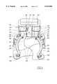
- FIG. 2is a rear, elevational, partially schematic view, from a viewing position directly opposite that of FIG. 1. and with certain features omitted, of the embodiment of FIG. 1;
- FIG. 3is a front, elevational, partially schematic view, from a viewing position corresponding to that of FIG. 1. and with certain features omitted, of the embodiment of FIG. 1;
- FIG. 4is a front, elevational, partially schematic view of the embodiment of the present invention shown in FIG. 1, illustrating the system in a first end position;
- FIG. 5is a front, elevational, partially schematic view of the embodiment of the present invention shown in FIG. 4, with the system in a neutral position;
- FIG. 6is a front, elevational, partially schematic view of the embodiment shown in FIG. 4 with the system in a second end position;
- FIG. 7is a partial, top, schematic detailed view of one embodiment of an armature and stator design in accordance with the present invention.
- FIG. 8is a top, schematic detailed view of another embodiment of the armature and stator design of the present invention.
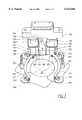
- FIG. 1shows an electromagnetic camera shutter arrangement according to one embodiment of the present invention.
- An armature 100is arranged to pivot around an axis 108.
- the armature 100is connected to a rocker arm 105 which, in turn and in a known manner, transmits the rocking movement of the armature 100 to a rotating movement of a plurality of shutter blades 200. This is achieved by the rocker arm being connected to the shutter blades 200 through linking rods 202, parallel rods 201, shutter blade levers 204 and shutter blade lever discs 205.
- sensor tabs 300Protruding from the parallel rods 201 are sensor tabs 300.
- the position of these sensor tabs 300are detected by sensors 301, for example opto-electronic sensors such as photo-interrupters of the reflective type.
- sensors 301for example opto-electronic sensors such as photo-interrupters of the reflective type.
- the leading edges of these sensor tabs 300are inclined with respect to the direction of travel of the sensor tabs 300. This increases the sensitivity of the detection.
- the sensors 301detect the overall mechanical movement of the sensor tabs 300, and not only the end positions, i.e. the positions corresponding to the end positions of the armature 100.
- the armature 100is situated midway between the open ends 109 and 110 of a stator arrangement 101 forming part of the electromagnetic means.
- the stator 101is generally U-shaped, and has at least one electromagnetic coil 102 arranged close to the open ends, 109 and 110, of the stator 101.
- the open ends, 109 and 110, of the statorare extensions to the U-shape, and are perpendicular to the general plane of the U-shape.
- the armature 100is, furthermore, biased towards a neutral position or zone between the two open ends, 109 and 110, of the stator 101 by a force exerted by a biasing means 104.
- This biasing means 104can comprise any linear or non-linear means for biasing the system towards a neutral zone, for example, one or more torsion springs, leaf springs, tension springs or compression springs, supplementary permanent magnet or magnets, or any kind of elastic means such as rubber means.
- permanent magnets 103Arranged close to the open ends, 109 and 110, of the stator 101 are permanent magnets 103. These permanent magnets 103, create a magnetic field which flows in opposite directions towards the armature 100. One field flows from a first permanent magnet 103 which is situated at the particular end position which the armature 100 is occupying when it is at a first end position, through the armature 100 and then through that open end 109 of the stator 101 which is in contact with the armature 100 back to the permanent magnet 103.
- the other fieldflows from a second permanent magnet 103, which is arranged on the opposite side of the stator 101 compared to the first permanent magnet 103, through the armature 100 and then through the same open end 109 of the stator 101 back to the second permanent magnet 103, but by means of the closed end 107 of the stator 103 (which is visible in FIG. 2 but covered by a holder 106 in FIG. 1).
- the combined force of these two fieldsholds the armature in either of its two end positions, while completely counteracting the force of the biasing means 104, which strives to return the armature 100 to the neutral position.
- a further improved embodimentcomprises a two capacitor discharge system where two voltages are applied in succession over the coils 102.
- a smaller capacity, high voltage capacitorprovides a higher voltage during the initial stage of the process. This yields a high current so that the current quickly reaches a sufficient level.
- the armature 100starts to move, this current can be driven by a lower voltage supply due to the decreased inductance of the system.
- a higher capacity, lower voltage capacitorwhich either has been discharging since the smaller capacity, high voltage capacitor started discharging, or which starts discharging when the smaller capacity, high voltage capacitor has lost its charge, provides the voltage needed towards the end phase of the process when the armature has to reach its opposite end position to that from which it started.
- Control means for controlling the mechanical movement system when displacement of the system diverges from the expectedis also present but not indicated in the figures.
- the control meanscan be of any known type, e.g. integrated in a camera's electronic control system.
- a holder 106is visible.
- This holderserves, inter alia, as a holding means for the biasing means 104.
- FIG. 2shows more clearly the relative arrangement of the armature 100 and the open ends, 109 and 110, of the stator 101, and, furthermore, shows one embodiment of the biasing means 104 in more detail. Also visible is the closed end 107 of the stator 101.
- FIG. 3corresponds to FIG. 1, but with several details removed for clarity.
- FIG. 4shows the electromagnetic camera shutter arrangement according to FIG. 1 (with the holder 106 removed), but with the shutter blades 200 in a closed position. This is the shutter position which is used during periods between film frame exposures.
- FIG. 5shows the same electromagnetic camera shutter arrangement as in FIG. 4, but where the armature 100 is in the neutral position and, thus, the shutter blades 200 are in a midway position between fully closed and fully opened positions.
- FIG. 6shows the same electromagnetic camera shutter arrangement as in FIGS. 4 and 5, but now the shutter blades 200 have reached the fully opened position. After a predetermined time, which depends upon the desired total opening time of the shutter, the armature 100 is released and travels back to the position it had in FIG. 4.
- FIG. 7A preferred embodiment of armature design is shown in FIG. 7, where the armature top surface is tapered in two steps, 100A and 100B, respectively.
- the two open ends, 109 and 110, of the stator 101are correspondingly negatively tapered into different surfaces, 109A, 109B, 110A, and 110B, so that the armature 100 at its two end positions is contacting the stator open ends, 109 and 110, at the surfaces, 109A and 110A, which correspond to one of the armature taper surfaces 100A.
- the remaining stator open end surfaces, 109B and 110Bare not in contact with the armature 100 when the armature 100 is at either of its end positions.
- FIG. 8A further preferred embodiment of armature design is shown in FIG. 8, where the two open ends, 109 and 110, of the stator 101 are tapered into different surfaces, 109A, 109B, 110A and 110B, and the armature top surface is correspondingly negatively tapered into different surfaces, 100A and 100B.
- the function of the armature/stator interactionis the same as for FIG. 7.
- the present inventionis not restricted to the embodiments described above or shown in the drawings, but may be varied within the scope of the appended claims. While the examples have been directed towards shutters, it is to be understood that the principles of the present invention may advantageously be applied to any camera system or optical viewing device. For example, the present invention may also be applied to the aperture, diaphragm or viewing mirror mechanisms of a camera. Also, different types of shutters are suitable for the invention, such as lens shutters or focal plane shutters. While the spring means have been described as biasing the mechanical system towards a neutral position, it is to be understood that the neutral position may in fact be a neutral zone between the end positions, such a neutral zone being defined as a zone in which the resultant force from the spring means an the mechanical system is zero.
Landscapes
- Physics & Mathematics (AREA)
- General Physics & Mathematics (AREA)
- Shutters For Cameras (AREA)
- Reciprocating, Oscillating Or Vibrating Motors (AREA)
Abstract
Description
The present invention relates to an electromagnetic displacement means for effecting cyclic displacement of a mechanical system, such as a shutter mechanism, mirror mechanism, and the like, in a camera, between two end positions.
Most cameras are provided with one or more mechanical systems which, during the sequence of taking a picture, are displaced from one end position to another, and thereafter returned to the first end position in readiness for the taking of a subsequent picture. Such systems include, for example, the viewing mirror mechanism of a single lens reflex camera, and/or the shutter mechanism and/or the diaphragm mechanism.
In terms of the viewing mirror mechanism, a common displacement means includes a return setting member, a mirror-up spring and an associated return spring, a latch and a mirror-up mechanism. A shutter charging operation energizes both the mirror-up spring and the return spring while bringing the return setting member to its set position, where it is locked by the latch. A shutter release causes the mirror-up member to be initially actuated under the influence of the mirror-up spring to drive the mirror upward. Immediately after termination of shutter operation the return setting member is unlocked from the latch, thereby allowing the setting member to be returned under the influence of the return spring until the mirror returns to its original position.
The above-described mechanism suffers from many disadvantages. Firstly, to guarantee that the mirror will indeed reach its end positions, even if the camera in which it is fitted is operated in an inverted state, the two springs must be sufficiently tensioned to overcome mechanical losses so that the mirror arrives at the end positions with at least some tension remaining in the springs. This results in the mirror being accelerated during its entire movement and therefore reaching its end positions at a maximum velocity for that movement. At the end positions the kinetic energy of the mirror and driving mechanism must be absorbed and, due to the relatively high velocity, the deceleration forces can be sufficiently high to cause the camera to shake, thereby giving rise to a blurred picture. The high velocity of the mirror also creates problems with latching of the mirror at its end positions, since the mirror can bounce back before the latch engages. The requisite high deceleration forces lead to increased noise levels and vibration while decreasing the lifespan of the camera.
Many partial solutions to the above-described problem have been proposed. For example, PCT Application No. WO 93/025935 provides a solution for effecting cyclic displacement of a mechanical system, such as a mirror mechanism, shutter mechanism, and the like in a camera, between two end positions, which avoids the risk of bounce, requires a minimal amount of energy and which is simpler than previous solutions. This is achieved by including spring means for biasing the system towards a neutral position or zone between these end positions, and drive means, activated during displacement of the system, for ensuring that the system sequentially reaches these end positions. This arrangement can also be used for cyclic displacement of a mechanical system, such as a mirror mechanism, shutter mechanism, and the like in a camera, between two end positions. The solution consists of the following steps:
I) biasing the system towards a neutral position or zone between the end positions;
II) retaining the system at one of the two end positions;
III) releasing the system from the one end position;
IV) providing an additional force to the system above that due to the biasing to ensure that the system reaches the other of the two end positions;
V) retaining the system at the other end position;
VI) releasing the system from the other end position; and
VII) providing an additional force to the system above that due to the biasing to ensure that the system reaches the one end position.
Since the system is biased towards a neutral position or zone between the end positions, the maximum velocity of the component occurs at this neutral position or zone during movement from one end position to the other. Similarly, the velocity of the system, and therefore its kinetic energy, tends to zero when approaching the end positions. As such, no complicated braking or damping system is necessitated and latching is simplified.
One disadvantage of this solution is its relative lack of speed, i.e. the system cannot react fast enough when a rapid movement is required. This is desired for fast shutter speeds in camera shutters, for example, where high speed movement of the shutter blades or curtains are essential.
Shutter operation detection devices of different types are known. U.S. Pat. No. 5,532,785 describes a system which uses a light emitting diode (LED) and a photo transistor (PTR) placed in proximity to the shutter curtains to measure the actual exposure times. The difference between the control exposure time, which is based upon the brightness value of the subject to be photographed and the film sensitivity, and the measured exposure time, is determined. The control exposure time for the next session can then be corrected based upon this difference. This system measures the time between passing of the front curtain and the rear curtain of a shutter made up of two shutter curtains by detecting reflected light bounced from the LED by means of a curtain blade to the PTR.
One disadvantage with this system is that no information is obtained as to the actual position of the shutter blades at any chosen time in the interval from start of exposure to end of exposure, ie. going from fully closed shutter to fully open shutter and back to fully closed shutter.
It is therefore an object of the present invention to provide an electromagnetic displacement means for effecting cyclic displacement of a mechanical system, such as a shutter mechanism, mirror mechanism, and the like in a camera, between two end positions, which means is capable of high speed movements with repeatability and stability, while requiring a minimal amount of energy and which is simple in construction.
In accordance with the present invention, this and other objects have now been achieved by the discovery of apparatus for the cyclic displacement of a camera mechanism between first and second end positions comprising electromagnetic means for displacing the camera mechanism, the electromagnetic means comprising a pivotable armature pivotable between first and second end positions, a plurality of blade members, a rocker arm connected to the armature, linking means connecting the rocker arm to the plurality of blade members whereby the pivoting of the armature can be translated into rotary movement of the plurality of blade members, biasing means for biasing the armature towards a neutral position between the first and second end positions, drive means for insuring that the armature reaches the first and second end positions, the drive means comprising permanent magnet means for holding the armature in either of the first and second end positions and counteracting the biasing means, and at least one coil for exerting a force on the armature upon activation of the at least one coil, the force being sufficient to overcome the permanent magnet means and the biasing means. In a preferred embodiment, the apparatus includes monitoring means for monitoring the displacement of the camera mechanism and control means for controlling the drive means in response to the monitoring means.
In accordance with one embodiment of the apparatus of the present invention, the camera mechanism comprises a viewing mirror. In another embodiment, the camera mechanism comprises a shutter mechanism.
In accordance with one embodiment of the apparatus of the present invention, the biasing means comprises spring means, preferably a pair of opposed spring members. The spring means can also comprise a leaf spring, a tension spring, or a compression spring.
In accordance with another embodiment of the apparatus of the present invention, the pivotable armature includes a pair of surfaces, each of the pair of surfaces including a plurality of tapered surfaces, and wherein the electromagnetic means includes a stator having a pair of ends proximate to the pair of surfaces of the pivotable armature, each of the pair of ends of the stator including a plurality of tapered surfaces whereby one of the plurality of tapered surfaces of the armature contacts one of the plurality of tapered surfaces of the stator when the stator is at the first and second end positions.
The objects of the present invention are achieved by means of arranging permanent magnets so that they cooperate to pull the system towards the end positions, exerting a force which, when the system is at one of the end positions, is higher than the force of the bias means towards the neutral position.
A further objective of the present invention is to provide a means for obtaining information as to the actual position of the shutter blades at any chosen time in the interval from start of exposure to end of exposure, i.e. going from a fully closed shutter to a fully open shutter and back to a fully closed shutter.
This object is achieved in accordance with the present invention by means of arranging sensor tabs suitably placed, e.g. on the linkage system which transmits the movement to the shutter blades, which sensor tabs position is detected by sensors.
The present invention will be described in more detail in the following detailed descrition, and with reference to the attached drawings, in which:
FIG. 1 is a front, elevational, partially schematic view of an embodiment of an electromagnetic displacement means according to the present invention;
FIG. 2 is a rear, elevational, partially schematic view, from a viewing position directly opposite that of FIG. 1. and with certain features omitted, of the embodiment of FIG. 1;
FIG. 3 is a front, elevational, partially schematic view, from a viewing position corresponding to that of FIG. 1. and with certain features omitted, of the embodiment of FIG. 1;
FIG. 4 is a front, elevational, partially schematic view of the embodiment of the present invention shown in FIG. 1, illustrating the system in a first end position;
FIG. 5 is a front, elevational, partially schematic view of the embodiment of the present invention shown in FIG. 4, with the system in a neutral position;
FIG. 6 is a front, elevational, partially schematic view of the embodiment shown in FIG. 4 with the system in a second end position;
FIG. 7 is a partial, top, schematic detailed view of one embodiment of an armature and stator design in accordance with the present invention; and
FIG. 8 is a top, schematic detailed view of another embodiment of the armature and stator design of the present invention.
FIG. 1 shows an electromagnetic camera shutter arrangement according to one embodiment of the present invention. Anarmature 100 is arranged to pivot around anaxis 108. Thearmature 100 is connected to arocker arm 105 which, in turn and in a known manner, transmits the rocking movement of thearmature 100 to a rotating movement of a plurality ofshutter blades 200. This is achieved by the rocker arm being connected to theshutter blades 200 through linkingrods 202,parallel rods 201, shutter blade levers 204 and shutterblade lever discs 205.
Protruding from theparallel rods 201 aresensor tabs 300. The position of thesesensor tabs 300 are detected bysensors 301, for example opto-electronic sensors such as photo-interrupters of the reflective type. Advantageously, the leading edges of thesesensor tabs 300 are inclined with respect to the direction of travel of thesensor tabs 300. This increases the sensitivity of the detection. Thesensors 301 detect the overall mechanical movement of thesensor tabs 300, and not only the end positions, i.e. the positions corresponding to the end positions of thearmature 100.
Thearmature 100 is situated midway between the open ends 109 and 110 of astator arrangement 101 forming part of the electromagnetic means. Thestator 101 is generally U-shaped, and has at least oneelectromagnetic coil 102 arranged close to the open ends, 109 and 110, of thestator 101. The open ends, 109 and 110, of the stator are extensions to the U-shape, and are perpendicular to the general plane of the U-shape. Thearmature 100 is, furthermore, biased towards a neutral position or zone between the two open ends, 109 and 110, of thestator 101 by a force exerted by a biasing means 104. This biasing means 104 can comprise any linear or non-linear means for biasing the system towards a neutral zone, for example, one or more torsion springs, leaf springs, tension springs or compression springs, supplementary permanent magnet or magnets, or any kind of elastic means such as rubber means.
Arranged close to the open ends, 109 and 110, of thestator 101 arepermanent magnets 103. Thesepermanent magnets 103, create a magnetic field which flows in opposite directions towards thearmature 100. One field flows from a firstpermanent magnet 103 which is situated at the particular end position which thearmature 100 is occupying when it is at a first end position, through thearmature 100 and then through thatopen end 109 of thestator 101 which is in contact with thearmature 100 back to thepermanent magnet 103. The other field flows from a secondpermanent magnet 103, which is arranged on the opposite side of thestator 101 compared to the firstpermanent magnet 103, through thearmature 100 and then through the sameopen end 109 of thestator 101 back to the secondpermanent magnet 103, but by means of theclosed end 107 of the stator 103 (which is visible in FIG. 2 but covered by aholder 106 in FIG. 1). The combined force of these two fields holds the armature in either of its two end positions, while completely counteracting the force of the biasing means 104, which strives to return thearmature 100 to the neutral position.
In order to move thearmature 100 from either of its end positions, a current is applied incoils 102, so that the force of thepermanent magnets 103 is overcome. Because of the bias means 104 pressing towards the neutral position of thearmature 100, the necessary force, and thus necessary current, is lower than if the bias means 104 had not been present.
A further improved embodiment comprises a two capacitor discharge system where two voltages are applied in succession over thecoils 102. A smaller capacity, high voltage capacitor provides a higher voltage during the initial stage of the process. This yields a high current so that the current quickly reaches a sufficient level. When thearmature 100 starts to move, this current can be driven by a lower voltage supply due to the decreased inductance of the system. A higher capacity, lower voltage capacitor, which either has been discharging since the smaller capacity, high voltage capacitor started discharging, or which starts discharging when the smaller capacity, high voltage capacitor has lost its charge, provides the voltage needed towards the end phase of the process when the armature has to reach its opposite end position to that from which it started.
This improves the shutter response because a smaller amount of energy has to be charged into the capacitors before the process of shutter blade movement can start, which means that the delay between pressing the shutter release button and the shutter starting its movement is decreased. The total energy consumption of the electromagnetic shutter system is also lowered.
Control means for controlling the mechanical movement system when displacement of the system diverges from the expected is also present but not indicated in the figures. The control means can be of any known type, e.g. integrated in a camera's electronic control system.
In FIG. 1, furthermore, aholder 106 is visible. This holder serves, inter alia, as a holding means for the biasing means 104.
FIG. 2 shows more clearly the relative arrangement of thearmature 100 and the open ends, 109 and 110, of thestator 101, and, furthermore, shows one embodiment of the biasing means 104 in more detail. Also visible is theclosed end 107 of thestator 101.
FIG. 3 corresponds to FIG. 1, but with several details removed for clarity.
FIG. 4 shows the electromagnetic camera shutter arrangement according to FIG. 1 (with theholder 106 removed), but with theshutter blades 200 in a closed position. This is the shutter position which is used during periods between film frame exposures.
FIG. 5 shows the same electromagnetic camera shutter arrangement as in FIG. 4, but where thearmature 100 is in the neutral position and, thus, theshutter blades 200 are in a midway position between fully closed and fully opened positions.
FIG. 6 shows the same electromagnetic camera shutter arrangement as in FIGS. 4 and 5, but now theshutter blades 200 have reached the fully opened position. After a predetermined time, which depends upon the desired total opening time of the shutter, thearmature 100 is released and travels back to the position it had in FIG. 4.
A preferred embodiment of armature design is shown in FIG. 7, where the armature top surface is tapered in two steps, 100A and 100B, respectively. The two open ends, 109 and 110, of thestator 101 are correspondingly negatively tapered into different surfaces, 109A, 109B, 110A, and 110B, so that thearmature 100 at its two end positions is contacting the stator open ends, 109 and 110, at the surfaces, 109A and 110A, which correspond to one of the armature taper surfaces 100A. The remaining stator open end surfaces, 109B and 110B, are not in contact with thearmature 100 when thearmature 100 is at either of its end positions. This has the effect that the magnetic field holding thearmature 100 is initially concentrated to asmaller surface 100A, when thearmature 100 makes contact with the stator open ends, 109 and 110, but after the release of electric current in thecoils 102, thearmature 100 loses contact with the stator open ends, 109 and 110, thus enlarging the magnetic field area to include also the surface, 109B and 110B, of the stator open ends, albeit with an air gap in-between which lowers the strength of the field further.
A further preferred embodiment of armature design is shown in FIG. 8, where the two open ends, 109 and 110, of thestator 101 are tapered into different surfaces, 109A, 109B, 110A and 110B, and the armature top surface is correspondingly negatively tapered into different surfaces, 100A and 100B. The function of the armature/stator interaction is the same as for FIG. 7.
The present invention is not restricted to the embodiments described above or shown in the drawings, but may be varied within the scope of the appended claims. While the examples have been directed towards shutters, it is to be understood that the principles of the present invention may advantageously be applied to any camera system or optical viewing device. For example, the present invention may also be applied to the aperture, diaphragm or viewing mirror mechanisms of a camera. Also, different types of shutters are suitable for the invention, such as lens shutters or focal plane shutters. While the spring means have been described as biasing the mechanical system towards a neutral position, it is to be understood that the neutral position may in fact be a neutral zone between the end positions, such a neutral zone being defined as a zone in which the resultant force from the spring means an the mechanical system is zero.
Although the invention herein has been described with reference to particular embodiments, it is to be understood that these embodiments are merely illustrative of the principles and applications of the present invention. It is therefore to be understood that numerous modifications may be made to the illustrative embodiments and that other arrangements may be devised without departing from the spirit and scope of the present invention as defined by the appended claims.
Claims (10)
1. Apparatus for the cyclic displacement of a camera mechanism between first and second end positions comprising electromagnetic means for displacing said camera mechanism, said electromagnetic means comprising a pivotable armature pivotable between first and second end positions, a plurality of blade members, a rocker arm connected to said armature, linking means connecting said rocker arm to said plurality of blade members whereby said pivoting of said armature can be translated into rotary movement of said plurality of blade members, biasing means for biasing said armature towards a neutral position between said first and second end positions, drive means for insuring that said armature reaches said first and second end positions, said drive means comprising permanent magnet means for holding said armature in either of said first and second end positions and counteracting said biasing means, and at least one coil for exerting a force on said armature upon activation of said at least one coil, said force being sufficient to overcome said permanent magnet means and said biasing means.
2. The apparatus of claim 1 including monitoring means for monitoring said displacement of said camera mechanism and control means for controlling said drive means in response to said monitoring means.
3. The apparatus of claim 1 wherein said camera mechanism comprises a viewing mirror.
4. The apparatus of claim 1 wherein said camera mechanism comprises a shutter mechanism.
5. The apparatus of claim 1 wherein said biasing means comprises spring means.
6. The apparatus of claim 5 wherein said spring means comprises a pair of opposed spring members.
7. The apparatus of claim 5 wherein said spring means comprises a leaf spring.
8. The apparatus of claim 5 wherein said spring means comprises a tension spring.
9. The apparatus of claim 5 wherein said spring means comprises a compression spring.
10. The apparatus of claim 1 wherein said pivotable armature includes a pair of surfaces, each of said pair of surfaces including a plurality of tapered surfaces, and wherein said electromagnetic means includes a stator having a pair of ends proximate to said pair of surfaces of said pivotable armature, each of said pair of ends of said stator including a plurality of tapered surfaces whereby one of said plurality of tapered surfaces of said armature contacts one of said plurality of tapered surfaces of said stator when said stator is at said first and second end positions.
Applications Claiming Priority (3)
| Application Number | Priority Date | Filing Date | Title |
|---|---|---|---|
| SE9700434ASE9700434L (en) | 1997-02-06 | 1997-02-06 | Electromagnetic displacement means |
| SE9700434 | 1997-02-06 | ||
| PCT/SE1998/000147WO1998035268A1 (en) | 1997-02-06 | 1998-02-02 | Electromagnetic displacement means |
Publications (1)
| Publication Number | Publication Date |
|---|---|
| US6123466Atrue US6123466A (en) | 2000-09-26 |
Family
ID=20405715
Family Applications (1)
| Application Number | Title | Priority Date | Filing Date |
|---|---|---|---|
| US09/355,694Expired - LifetimeUS6123466A (en) | 1997-02-06 | 1998-02-02 | Electromagnetic displacement means |
Country Status (5)
| Country | Link |
|---|---|
| US (1) | US6123466A (en) |
| JP (1) | JP3944751B2 (en) |
| DE (1) | DE19881927T1 (en) |
| SE (1) | SE9700434L (en) |
| WO (1) | WO1998035268A1 (en) |
Cited By (26)
| Publication number | Priority date | Publication date | Assignee | Title |
|---|---|---|---|---|
| US6899472B2 (en)* | 2001-09-26 | 2005-05-31 | Olympus Optical Co., Ltd. | Electromagnetic drive |
| US20070146537A1 (en)* | 2005-11-07 | 2007-06-28 | Canon Kabushiki Kaisha | Apparatus and method for controlling diaphragm of imaging apparatus |
| US20070255273A1 (en)* | 2006-04-29 | 2007-11-01 | Board Of Regents, The University Of Texas System | Devices for use in Transluminal and Endoluminal Surgery |
| WO2008034439A3 (en)* | 2006-09-21 | 2008-05-08 | Rollei Gmbh | Mirror drive for a camera |
| US20080269779A1 (en)* | 2003-12-02 | 2008-10-30 | Board Of Regents, The University Of Texas System | Surgical anchor and system |
| US20090074398A1 (en)* | 2004-04-09 | 2009-03-19 | Vision Iii Imaging, Inc. | Optical Element Parallax Scanning Device |
| US10172669B2 (en) | 2009-10-09 | 2019-01-08 | Ethicon Llc | Surgical instrument comprising an energy trigger lockout |
| US10314638B2 (en) | 2015-04-07 | 2019-06-11 | Ethicon Llc | Articulating radio frequency (RF) tissue seal with articulating state sensing |
| US10603117B2 (en) | 2017-06-28 | 2020-03-31 | Ethicon Llc | Articulation state detection mechanisms |
| US10751109B2 (en) | 2014-12-22 | 2020-08-25 | Ethicon Llc | High power battery powered RF amplifier topology |
| US10751117B2 (en) | 2016-09-23 | 2020-08-25 | Ethicon Llc | Electrosurgical instrument with fluid diverter |
| US10779876B2 (en) | 2011-10-24 | 2020-09-22 | Ethicon Llc | Battery powered surgical instrument |
| US10799284B2 (en) | 2017-03-15 | 2020-10-13 | Ethicon Llc | Electrosurgical instrument with textured jaws |
| US10856934B2 (en) | 2016-04-29 | 2020-12-08 | Ethicon Llc | Electrosurgical instrument with electrically conductive gap setting and tissue engaging members |
| US10959806B2 (en) | 2015-12-30 | 2021-03-30 | Ethicon Llc | Energized medical device with reusable handle |
| US10959771B2 (en) | 2015-10-16 | 2021-03-30 | Ethicon Llc | Suction and irrigation sealing grasper |
| US10987156B2 (en) | 2016-04-29 | 2021-04-27 | Ethicon Llc | Electrosurgical instrument with electrically conductive gap setting member and electrically insulative tissue engaging members |
| CN112882315A (en)* | 2019-11-15 | 2021-06-01 | 台湾东电化股份有限公司 | Optical element driving mechanism |
| US11033325B2 (en) | 2017-02-16 | 2021-06-15 | Cilag Gmbh International | Electrosurgical instrument with telescoping suction port and debris cleaner |
| US11033323B2 (en) | 2017-09-29 | 2021-06-15 | Cilag Gmbh International | Systems and methods for managing fluid and suction in electrosurgical systems |
| US11090103B2 (en) | 2010-05-21 | 2021-08-17 | Cilag Gmbh International | Medical device |
| WO2022033632A1 (en)* | 2020-08-12 | 2022-02-17 | Jenoptik Optical Systems Gmbh | Camera shutter device having a two-armed lever |
| US11484358B2 (en) | 2017-09-29 | 2022-11-01 | Cilag Gmbh International | Flexible electrosurgical instrument |
| US11490951B2 (en) | 2017-09-29 | 2022-11-08 | Cilag Gmbh International | Saline contact with electrodes |
| US11497546B2 (en) | 2017-03-31 | 2022-11-15 | Cilag Gmbh International | Area ratios of patterned coatings on RF electrodes to reduce sticking |
| US11957342B2 (en) | 2021-11-01 | 2024-04-16 | Cilag Gmbh International | Devices, systems, and methods for detecting tissue and foreign objects during a surgical operation |
Citations (9)
| Publication number | Priority date | Publication date | Assignee | Title |
|---|---|---|---|---|
| US3595153A (en)* | 1969-07-28 | 1971-07-27 | Tektronix Inc | Electrically operated shutter |
| US4279485A (en)* | 1979-01-04 | 1981-07-21 | Ernst Krull & Co. Gmbh | Electromagnetic drive system for photographic shutters |
| US4326786A (en)* | 1979-11-16 | 1982-04-27 | Canon Kabushiki Kaisha | Electromagnetically driven shutter |
| US4564278A (en)* | 1983-03-31 | 1986-01-14 | Fuji Photo Film Co., Ltd. | Exposure control device for camera |
| US4881093A (en)* | 1988-04-21 | 1989-11-14 | Eastman Kodak Company | Electromagnetic shutter apparatus |
| DE4203750A1 (en)* | 1991-02-12 | 1992-08-13 | Martin Heinze | Electromagnetically operable central shutter for photographic camera - has springs for shutter blades free from tension when armatures are abutted against permanently magnetised stops |
| WO1993025935A1 (en)* | 1992-06-09 | 1993-12-23 | Victor Hasselblad Ab | Camera mechanism displacement means |
| WO1996002018A1 (en)* | 1994-07-09 | 1996-01-25 | Martin Heinze | Electromagnetically actuatable central shutter for photographic camera |
| US5532785A (en)* | 1993-03-12 | 1996-07-02 | Nikon Corporation | Camera having means for correcting shutter time by measuring the actual exposure time |
- 1997
- 1997-02-06SESE9700434Apatent/SE9700434L/ennot_activeApplication Discontinuation
- 1998
- 1998-02-02DEDE19881927Tpatent/DE19881927T1/ennot_activeWithdrawn
- 1998-02-02JPJP53424398Apatent/JP3944751B2/ennot_activeExpired - Fee Related
- 1998-02-02USUS09/355,694patent/US6123466A/ennot_activeExpired - Lifetime
- 1998-02-02WOPCT/SE1998/000147patent/WO1998035268A1/enactiveApplication Filing
Patent Citations (10)
| Publication number | Priority date | Publication date | Assignee | Title |
|---|---|---|---|---|
| US3595153A (en)* | 1969-07-28 | 1971-07-27 | Tektronix Inc | Electrically operated shutter |
| US4279485A (en)* | 1979-01-04 | 1981-07-21 | Ernst Krull & Co. Gmbh | Electromagnetic drive system for photographic shutters |
| US4326786A (en)* | 1979-11-16 | 1982-04-27 | Canon Kabushiki Kaisha | Electromagnetically driven shutter |
| US4564278A (en)* | 1983-03-31 | 1986-01-14 | Fuji Photo Film Co., Ltd. | Exposure control device for camera |
| US4881093A (en)* | 1988-04-21 | 1989-11-14 | Eastman Kodak Company | Electromagnetic shutter apparatus |
| DE4203750A1 (en)* | 1991-02-12 | 1992-08-13 | Martin Heinze | Electromagnetically operable central shutter for photographic camera - has springs for shutter blades free from tension when armatures are abutted against permanently magnetised stops |
| WO1993025935A1 (en)* | 1992-06-09 | 1993-12-23 | Victor Hasselblad Ab | Camera mechanism displacement means |
| US5598244A (en)* | 1992-06-09 | 1997-01-28 | Victor Hasselblad Ab | Camera mechanism displacement means |
| US5532785A (en)* | 1993-03-12 | 1996-07-02 | Nikon Corporation | Camera having means for correcting shutter time by measuring the actual exposure time |
| WO1996002018A1 (en)* | 1994-07-09 | 1996-01-25 | Martin Heinze | Electromagnetically actuatable central shutter for photographic camera |
Cited By (40)
| Publication number | Priority date | Publication date | Assignee | Title |
|---|---|---|---|---|
| US6899472B2 (en)* | 2001-09-26 | 2005-05-31 | Olympus Optical Co., Ltd. | Electromagnetic drive |
| US9033957B2 (en) | 2003-12-02 | 2015-05-19 | Board Of Regents, The University Of Texas System | Surgical anchor and system |
| US20080269779A1 (en)* | 2003-12-02 | 2008-10-30 | Board Of Regents, The University Of Texas System | Surgical anchor and system |
| US7832949B2 (en)* | 2004-04-09 | 2010-11-16 | Vision Iii Imaging, Inc. | Optical element parallax scanning device |
| US20090074398A1 (en)* | 2004-04-09 | 2009-03-19 | Vision Iii Imaging, Inc. | Optical Element Parallax Scanning Device |
| US7675568B2 (en)* | 2005-11-07 | 2010-03-09 | Canon Kabushiki Kaisha | Apparatus and method for controlling diaphragm of imaging apparatus |
| US20070146537A1 (en)* | 2005-11-07 | 2007-06-28 | Canon Kabushiki Kaisha | Apparatus and method for controlling diaphragm of imaging apparatus |
| US7691103B2 (en) | 2006-04-29 | 2010-04-06 | Board Of Regents, The University Of Texas System | Devices for use in transluminal and endoluminal surgery |
| US8480668B2 (en) | 2006-04-29 | 2013-07-09 | Board Of Regents Of The University Of Texas System | Devices for use in transluminal and endoluminal surgery |
| US20070255273A1 (en)* | 2006-04-29 | 2007-11-01 | Board Of Regents, The University Of Texas System | Devices for use in Transluminal and Endoluminal Surgery |
| US20100027984A1 (en)* | 2006-09-21 | 2010-02-04 | Hartung Hans-Juergen | Mirror drive for a camera |
| WO2008034439A3 (en)* | 2006-09-21 | 2008-05-08 | Rollei Gmbh | Mirror drive for a camera |
| US10172669B2 (en) | 2009-10-09 | 2019-01-08 | Ethicon Llc | Surgical instrument comprising an energy trigger lockout |
| US11090103B2 (en) | 2010-05-21 | 2021-08-17 | Cilag Gmbh International | Medical device |
| US10779876B2 (en) | 2011-10-24 | 2020-09-22 | Ethicon Llc | Battery powered surgical instrument |
| US10751109B2 (en) | 2014-12-22 | 2020-08-25 | Ethicon Llc | High power battery powered RF amplifier topology |
| US10314638B2 (en) | 2015-04-07 | 2019-06-11 | Ethicon Llc | Articulating radio frequency (RF) tissue seal with articulating state sensing |
| US10959771B2 (en) | 2015-10-16 | 2021-03-30 | Ethicon Llc | Suction and irrigation sealing grasper |
| US10959806B2 (en) | 2015-12-30 | 2021-03-30 | Ethicon Llc | Energized medical device with reusable handle |
| US10856934B2 (en) | 2016-04-29 | 2020-12-08 | Ethicon Llc | Electrosurgical instrument with electrically conductive gap setting and tissue engaging members |
| US10987156B2 (en) | 2016-04-29 | 2021-04-27 | Ethicon Llc | Electrosurgical instrument with electrically conductive gap setting member and electrically insulative tissue engaging members |
| US10751117B2 (en) | 2016-09-23 | 2020-08-25 | Ethicon Llc | Electrosurgical instrument with fluid diverter |
| US12295644B2 (en) | 2016-09-23 | 2025-05-13 | Cilag Gmbh International | Electrosurgical instrument with fluid diverter |
| US11839422B2 (en) | 2016-09-23 | 2023-12-12 | Cilag Gmbh International | Electrosurgical instrument with fluid diverter |
| US11033325B2 (en) | 2017-02-16 | 2021-06-15 | Cilag Gmbh International | Electrosurgical instrument with telescoping suction port and debris cleaner |
| US10799284B2 (en) | 2017-03-15 | 2020-10-13 | Ethicon Llc | Electrosurgical instrument with textured jaws |
| US12023087B2 (en) | 2017-03-15 | 2024-07-02 | Cilag Gmbh International | Electrosurgical instrument with textured jaws |
| US11497546B2 (en) | 2017-03-31 | 2022-11-15 | Cilag Gmbh International | Area ratios of patterned coatings on RF electrodes to reduce sticking |
| US10603117B2 (en) | 2017-06-28 | 2020-03-31 | Ethicon Llc | Articulation state detection mechanisms |
| US11490951B2 (en) | 2017-09-29 | 2022-11-08 | Cilag Gmbh International | Saline contact with electrodes |
| US11484358B2 (en) | 2017-09-29 | 2022-11-01 | Cilag Gmbh International | Flexible electrosurgical instrument |
| US11033323B2 (en) | 2017-09-29 | 2021-06-15 | Cilag Gmbh International | Systems and methods for managing fluid and suction in electrosurgical systems |
| US12390264B2 (en) | 2017-09-29 | 2025-08-19 | Cilag Gmbh International | Systems and methods for managing fluid and suction in electrosurgical systems |
| US11852886B2 (en) | 2019-11-15 | 2023-12-26 | Tdk Taiwan Corp. | Optical element driving mechanism |
| CN112882315B (en)* | 2019-11-15 | 2024-06-11 | 台湾东电化股份有限公司 | Optical element drive mechanism |
| US12222576B2 (en) | 2019-11-15 | 2025-02-11 | Tdk Taiwan Corp. | Optical element driving mechanism |
| CN112882315A (en)* | 2019-11-15 | 2021-06-01 | 台湾东电化股份有限公司 | Optical element driving mechanism |
| WO2022033632A1 (en)* | 2020-08-12 | 2022-02-17 | Jenoptik Optical Systems Gmbh | Camera shutter device having a two-armed lever |
| US12228851B2 (en) | 2020-08-12 | 2025-02-18 | Jenoptik Optical Systems Gmbh | Camera shutter device having a two-armed lever |
| US11957342B2 (en) | 2021-11-01 | 2024-04-16 | Cilag Gmbh International | Devices, systems, and methods for detecting tissue and foreign objects during a surgical operation |
Also Published As
| Publication number | Publication date |
|---|---|
| SE9700434L (en) | 1998-08-07 |
| JP3944751B2 (en) | 2007-07-18 |
| WO1998035268A1 (en) | 1998-08-13 |
| DE19881927T1 (en) | 1999-12-23 |
| SE9700434D0 (en) | 1997-02-06 |
| JP2001510591A (en) | 2001-07-31 |
Similar Documents
| Publication | Publication Date | Title |
|---|---|---|
| US6123466A (en) | Electromagnetic displacement means | |
| JP2836827B2 (en) | Photo camera | |
| US6350068B1 (en) | Quantity-of-light adjusting device and optical apparatus having the same | |
| KR101490754B1 (en) | Shutter device | |
| US5598244A (en) | Camera mechanism displacement means | |
| KR101491631B1 (en) | Shutter device | |
| KR101437910B1 (en) | Shutter device capable of preventing foreign matter from adhering to magnetic sticking surface and camera including shutter device | |
| JP6526173B2 (en) | Shutter device and imaging device provided with shutter device | |
| US6640056B2 (en) | Camera for driving lens unit removably attached thereto and method for controlling drive therebetween | |
| JPS5846329A (en) | Camera count switch using photo interrupter | |
| US4720718A (en) | Reflex camera | |
| US4306797A (en) | Electromagnetically driven shutter | |
| JPH11288015A (en) | Image stabilizer | |
| JPH044573B2 (en) | ||
| US6006040A (en) | Shutter device for camera | |
| CA1115107A (en) | Electromagnet controlled scanning shutter blade arrangement | |
| US5144353A (en) | Optical system driving device of camera | |
| CN102749792B (en) | Camera | |
| US4355874A (en) | Program EE camera | |
| US4600289A (en) | Aperture control system for cameras | |
| JP2545354B2 (en) | Aperture controller for single-lens reflex camera | |
| JP4012314B2 (en) | Shutter device | |
| JPS5846330A (en) | Flash auto-system of camera using photointerrupter | |
| JP2717691B2 (en) | Electric shutter | |
| JPH0239775B2 (en) | SHATSUTAAKINOOJUSURUSAABOJIDOSHIBORISOCHI |
Legal Events
| Date | Code | Title | Description |
|---|---|---|---|
| AS | Assignment | Owner name:VICTOR HASSELBLAD AB, SWEDEN Free format text:ASSIGNMENT OF ASSIGNORS INTEREST;ASSIGNORS:PERSSON, KJELL-ANDERS;WIHLANDER, JOHAN;JOHANSSON, TOMAS;REEL/FRAME:010268/0658 Effective date:19990802 | |
| STCF | Information on status: patent grant | Free format text:PATENTED CASE | |
| FEPP | Fee payment procedure | Free format text:PAYOR NUMBER ASSIGNED (ORIGINAL EVENT CODE: ASPN); ENTITY STATUS OF PATENT OWNER: LARGE ENTITY | |
| FPAY | Fee payment | Year of fee payment:4 | |
| FPAY | Fee payment | Year of fee payment:8 | |
| AS | Assignment | Owner name:HASSELBLAD A/S, DENMARK Free format text:ASSIGNMENT OF ASSIGNORS INTEREST;ASSIGNOR:VICTOR HASSELBLAD AB;REEL/FRAME:021985/0175 Effective date:20081001 | |
| FPAY | Fee payment | Year of fee payment:12 | |
| AS | Assignment | Owner name:HASSELBLAD S.A.R.L., LUXEMBOURG Free format text:ASSIGNMENT OF ASSIGNORS INTEREST;ASSIGNOR:HASSELBLAD A/S;REEL/FRAME:030316/0232 Effective date:20130403 |