US6123434A - Fluorescent angle light - Google Patents
Fluorescent angle lightDownload PDFInfo
- Publication number
- US6123434A US6123434AUS09/236,528US23652899AUS6123434AUS 6123434 AUS6123434 AUS 6123434AUS 23652899 AUS23652899 AUS 23652899AUS 6123434 AUS6123434 AUS 6123434A
- Authority
- US
- United States
- Prior art keywords
- lens
- housing
- fluorescent
- lamp
- worklight
- Prior art date
- Legal status (The legal status is an assumption and is not a legal conclusion. Google has not performed a legal analysis and makes no representation as to the accuracy of the status listed.)
- Expired - Fee Related
Links
- 230000000295complement effectEffects0.000claims4
- 229920002457flexible plasticPolymers0.000claims1
- 239000004033plasticSubstances0.000description8
- 238000005286illuminationMethods0.000description6
- 239000000463materialSubstances0.000description3
- 238000012986modificationMethods0.000description2
- 230000004048modificationEffects0.000description2
- 230000006735deficitEffects0.000description1
- 238000003780insertionMethods0.000description1
- 230000037431insertionEffects0.000description1
- 239000000615nonconductorSubstances0.000description1
- 230000001681protective effectEffects0.000description1
Images


Classifications
- F—MECHANICAL ENGINEERING; LIGHTING; HEATING; WEAPONS; BLASTING
- F21—LIGHTING
- F21V—FUNCTIONAL FEATURES OR DETAILS OF LIGHTING DEVICES OR SYSTEMS THEREOF; STRUCTURAL COMBINATIONS OF LIGHTING DEVICES WITH OTHER ARTICLES, NOT OTHERWISE PROVIDED FOR
- F21V21/00—Supporting, suspending, or attaching arrangements for lighting devices; Hand grips
- F21V21/14—Adjustable mountings
- F21V21/145—Adjustable mountings for portable lighting devices
- F—MECHANICAL ENGINEERING; LIGHTING; HEATING; WEAPONS; BLASTING
- F21—LIGHTING
- F21L—LIGHTING DEVICES OR SYSTEMS THEREOF, BEING PORTABLE OR SPECIALLY ADAPTED FOR TRANSPORTATION
- F21L14/00—Electric lighting devices without a self-contained power source, e.g. for mains connection
- F21L14/02—Electric lighting devices without a self-contained power source, e.g. for mains connection capable of hand-held use, e.g. inspection lamps
- F21L14/026—Electric lighting devices without a self-contained power source, e.g. for mains connection capable of hand-held use, e.g. inspection lamps having a linear light source
- F—MECHANICAL ENGINEERING; LIGHTING; HEATING; WEAPONS; BLASTING
- F21—LIGHTING
- F21V—FUNCTIONAL FEATURES OR DETAILS OF LIGHTING DEVICES OR SYSTEMS THEREOF; STRUCTURAL COMBINATIONS OF LIGHTING DEVICES WITH OTHER ARTICLES, NOT OTHERWISE PROVIDED FOR
- F21V17/00—Fastening of component parts of lighting devices, e.g. shades, globes, refractors, reflectors, filters, screens, grids or protective cages
- F21V17/02—Fastening of component parts of lighting devices, e.g. shades, globes, refractors, reflectors, filters, screens, grids or protective cages with provision for adjustment
- F—MECHANICAL ENGINEERING; LIGHTING; HEATING; WEAPONS; BLASTING
- F21—LIGHTING
- F21V—FUNCTIONAL FEATURES OR DETAILS OF LIGHTING DEVICES OR SYSTEMS THEREOF; STRUCTURAL COMBINATIONS OF LIGHTING DEVICES WITH OTHER ARTICLES, NOT OTHERWISE PROVIDED FOR
- F21V19/00—Fastening of light sources or lamp holders
- F21V19/0075—Fastening of light sources or lamp holders of tubular light sources, e.g. ring-shaped fluorescent light sources
- F21V19/0095—Fastening of light sources or lamp holders of tubular light sources, e.g. ring-shaped fluorescent light sources of U-shaped tubular light sources, e.g. compact fluorescent tubes
- F—MECHANICAL ENGINEERING; LIGHTING; HEATING; WEAPONS; BLASTING
- F21—LIGHTING
- F21V—FUNCTIONAL FEATURES OR DETAILS OF LIGHTING DEVICES OR SYSTEMS THEREOF; STRUCTURAL COMBINATIONS OF LIGHTING DEVICES WITH OTHER ARTICLES, NOT OTHERWISE PROVIDED FOR
- F21V19/00—Fastening of light sources or lamp holders
- F21V19/02—Fastening of light sources or lamp holders with provision for adjustment, e.g. for focusing
- F—MECHANICAL ENGINEERING; LIGHTING; HEATING; WEAPONS; BLASTING
- F21—LIGHTING
- F21V—FUNCTIONAL FEATURES OR DETAILS OF LIGHTING DEVICES OR SYSTEMS THEREOF; STRUCTURAL COMBINATIONS OF LIGHTING DEVICES WITH OTHER ARTICLES, NOT OTHERWISE PROVIDED FOR
- F21V19/00—Fastening of light sources or lamp holders
- F21V19/04—Fastening of light sources or lamp holders with provision for changing light source, e.g. turret
- F—MECHANICAL ENGINEERING; LIGHTING; HEATING; WEAPONS; BLASTING
- F21—LIGHTING
- F21Y—INDEXING SCHEME ASSOCIATED WITH SUBCLASSES F21K, F21L, F21S and F21V, RELATING TO THE FORM OR THE KIND OF THE LIGHT SOURCES OR OF THE COLOUR OF THE LIGHT EMITTED
- F21Y2103/00—Elongate light sources, e.g. fluorescent tubes
- F21Y2103/30—Elongate light sources, e.g. fluorescent tubes curved
- F21Y2103/37—U-shaped
Definitions
- the present inventionrelates to a fluorescent worklight and, more particularly, a fluorescent worklight having the lamp socket as an integral part of an adjustable lampholder lens.
- This lampholder lensallows for positioning of the lamp towards the worksight and for simple replacement and removal of the lamp.
- Worklightscan be either of the incandescent or fluorescent lamp varieties. Where the fluorescent type worklight is employed, it is known in the art that a clear plastic lens is used which covers the entire fluorescent lamp as part of the light housing. The lens protects the delicate fluorescent lamp which is typically configured as an elonganted tube. Usually, the lens is attached to the housing by screws, plastic tabs or clips and must be removed entirely to provide access to the lamp for removal or replacement. Thus several inconvenient steps are necessary in the task of replacing a fluorescent lamp. This is further exacerbated in the fluorescent worklight in the known art because one end of the fluorescent lamp is connected to an electrical socket within the worklight housing and the other end is held in place within the housing, commonly by a rubber gasket or similar device.
- the lensalso confines the fluoresecent lamp within the housing and does not allow for positioning of the lamp itself with relation to the worksight. That is, the direction of illumination of the worksight is limited to the positioning of the worklight itself, which can be quite awkward and inefficient in a tightly confined workspace. Even if the lens were removed, it would be impractical to angle the fluorescent lamp to provide better illumination because the lamp is fixed in the socket in the handle of the worklight and held in position by the rubber gasket. Removal of the lens would also remove the protective features of the lens with respect to the lamp.
- the present inventionrelates to a fluorescent worklight and, more particularly, a fluorescent worklight having the lamp socket as an integral part of an adjustable lampholder lens.
- two cooperating half shells attached to one another by fastenersform a worklight housing.
- About half of the length of the worklight housingis configured as a handle.
- the other "half" of the length of the worklight housingconsists of a large opening for accommodating the fluorescent lamp.
- the opening in the worklight housing containing the fluorescent lampis covered by an adjustable lampholder lens.
- One end of the lampholder lenshas tabs or clips for removably fastening the lens to the worklight housing at one end of the opening.
- the other end of the lensis extended beyond the length of the housing opening and is inserted into the housing at the opposite end of the housing opening.
- the lensis designed to have a "U" -shaped cross-section so that the sides of the U-shape parallel the configuration of the inside of the worklight housing.
- Each "side" of the extended part of the lampholder lenscontains a curved flange on its outer surface, the surface facing the interior wall of the worklight housing.
- Each curved flangeis inserted into an arcuate track located on the inside of each of the half shells near the end of the opening for receiving the extended end of the lampholder lens.
- the extended end of the lampholder lensis also configured as the socket into which the fluorescent lamp is connected, forming an integral lens/socket unit. Electrical contacts for receiving the plug end of the lamp are contained within the lens/socket unit. When the lamp is inserted into the socket end of the lampholder lens, the lamp and lens also act as an integral unit. This is important for the proper operation of the adjustable lampholder lens to achieve the desired objectives.
- the usercan attain easy access to the fluorescent lamp for removal or replacement, or to postion the fluorescent lamp more advantageously, by disengaging the distant end of the lampholder lens removably attached at the distant end of the housing opening.
- the lampholder lensmay then pivot away from the worklight housing by the movement of the curved flanges on the socket end of the lampholder lens within the arcuate tracks on the inside of the worklight housing.
- the lampholder lensmay be pivoted from the worklight housing in this manner in an arc of varying degrees, with 90 degrees being a practical limitation.
- the lamp socketis an integral part of the lampholder lens
- the lampwhen plugged into the socket, moves in conjunction with the lens. In this manner, the lamp is positionable in an arc of up to 90 degrees with respect to the worklight housing to provide angled illumination to the work. Also, when the worklight is opened in this manner, the lamp may be easily accessed and replaced.
- FIG. 1is a perspective view of the fluorescent angle worklight in accordance with the present invention.
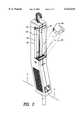
- FIG. 2is a further view of the fluorescent angle worklight of FIG. 1 with the lampholder lens in an open position;
- FIG. 3is an interior sectional view of the left housing section taken along line 3--3 of FIG. 2;
- FIG. 4is an interior sectional view of the right housing section taken along line 3--3 of FIG. 2;
- FIG. 5is a frontal view of the lampholder lens/lamp socket integral unit
- FIG. 5ais an inside view the lampholder lens/lamp socket integral unit with the lamp inserted
- FIG. 5bis an inside view of the lampholder lens/lamp socket integral unit with the lamp in a pre-insertable position
- FIG. 6is an exploded view of the left and right housing sections and a side view the lens/socket unit
- FIG. 1a fluorescent worklight 10, including a worklight housing 12, comprised of a right half shell 14 and a left half shell 16, a handle portion 18, a fluorescent lamp 20, a lampholder lens 22, a hook for hanging the worklight 26, an electrical receptacle 28 and an electric power cord 30.
- a worklight housing 12comprised of a right half shell 14 and a left half shell 16, a handle portion 18, a fluorescent lamp 20, a lampholder lens 22, a hook for hanging the worklight 26, an electrical receptacle 28 and an electric power cord 30.
- the worklight housing 12is constructed of an electrical insulator material such as plastic, for example, and is configured as an elongated, hollow structure which houses the electrical components.
- the hollow structure of the housingcould have any of a number of cross-sectional configurations such as round, oval, rectangular or, as shown, square.
- One end of the worklight housing, which comprises about half of its length,serves as a handle portion 18.
- the handle portion 18may consist of a cross-hatch pattern, or similar design, molded into the plastic of the housing to afford the user with a gripping surface.
- the length of the housing 12 opposite the handle portion 18is configured as an opening 32 for housing the fluorescent lamp 20 (see FIG. 2).
- the preferred embodiment of this inventionis designed to accommodate the common type of fluorescent lamp having a double tubular design and electrical prongs on one end. Accordingly, the housing opening 32 is also elongated to accommodate the lamp, and extends over most of the remaining length of the worklight housing that is opposite the handle portion.
- the lamp 20is connected to the worklight by plugging the prongs into a lamp socket 24 located inside the housing 16 and formed as an integral part of the lampholder lens 22 (see FIG. 5), further described below.
- the lampholder lens 22is designed to fit into the entire housing opening 32, essentially becoming part of worklight housing 12.
- the lampholder lens 22has a "U"-shape configuration to fit over the fluorescent lamp and provide protection therefor. Made of clear plastic material, the lens allows illumination from the lamp to pass through.
- the lampholder lens 22is removably attachable to the worklight housing 12 at the end of the opening 32 distant from the lens socket end 24, by means of tabs or clips 34.
- the tabs or clips 34are constructed as part of the lampholder lens 22 and are of the same material.
- the lampholder lens 22being plastic, has an inherent degree of flexibility which allows the tabs 34 to be compressed towards each other by the user, such that the tabs 34 can be inserted into the housing opening 32, holding the lens secure at that point.
- the end of the lampholder lens 22 opposite the end having the tabs 34extends beyond the length of the housing opening 32 and is configured as a socket for receiving the prongs of lamp 20.
- This socket end 24 of the lens 22fits into the worklight housing 12 at the near end of housing opening 32 when the worklight is assembled.
- the socket end 24 of the lens 22has the same U-shape as the lens 22, forming a compartment for holding the lamp 20.
- the interior of the compartmentcan be of any suitable design for accommodating and holding the lamp 20.
- the prongs 49 of the fluorescent lamp 20are plugged into electrical connectors 38 that are inserted into the socket end 24 of the lampholder lens 22.
- FIGS. 5a and 5bshow the lampholder lens 22 with lamp 20 inserted into socket end 24.
- FIG. 5bshows the lamp 20 prior to insertion or just after removal from the socket end 24.
- the two outer sides of the socket end 24each contain a curved flange 40 facing outwardly and toward the inner sides 42, 44 of the housing half shells 14, 16.
- the curve flanges 40fit into two corresponding arcuate tracks 46, 48 located on the interior sides 42,44 of half shells 14, 16.
- the arcuate tracks 46, 48are positioned at the end 50 of the opening 32 in a manner such that they receive the corresponding flanges 40 of the lampholder lens 22 when the lampholder lens 22 is in a closed position covering the housing opening 32.
- the closed positionis seen in FIG. 1.
- Both the flanges 40 and the arcuate tracks 46, 48have the same radius of curvature. This feature allows the flanges 40 to slide smoothly within the tracks 46, 48.
- the radiusacts as a pivot allowing the lens 22 to swing away from the worklight housing 12.
- the lampholder lensmay theoretically pivot any number of desired degrees from the housing, a practical limit may be 90 degrees as determined by the profile of the housing opening. In the embodiment shown, the lampholder lens 22 may pivot from 0 to 90 degrees to allow access to the fluorescent lamp or to position the lamp more advantageously.
Landscapes
- Engineering & Computer Science (AREA)
- General Engineering & Computer Science (AREA)
- Fastening Of Light Sources Or Lamp Holders (AREA)
Abstract
Description
Claims (6)
Priority Applications (1)
| Application Number | Priority Date | Filing Date | Title |
|---|---|---|---|
| US09/236,528US6123434A (en) | 1998-07-10 | 1999-01-25 | Fluorescent angle light |
Applications Claiming Priority (2)
| Application Number | Priority Date | Filing Date | Title |
|---|---|---|---|
| US9242798P | 1998-07-10 | 1998-07-10 | |
| US09/236,528US6123434A (en) | 1998-07-10 | 1999-01-25 | Fluorescent angle light |
Publications (1)
| Publication Number | Publication Date |
|---|---|
| US6123434Atrue US6123434A (en) | 2000-09-26 |
Family
ID=26785662
Family Applications (1)
| Application Number | Title | Priority Date | Filing Date |
|---|---|---|---|
| US09/236,528Expired - Fee RelatedUS6123434A (en) | 1998-07-10 | 1999-01-25 | Fluorescent angle light |
Country Status (1)
| Country | Link |
|---|---|
| US (1) | US6123434A (en) |
Cited By (29)
| Publication number | Priority date | Publication date | Assignee | Title |
|---|---|---|---|---|
| USD458400S1 (en) | 2001-03-13 | 2002-06-04 | Alert Safety Lite Products Co., Inc. | Double lamp utility light |
| US20030095404A1 (en)* | 2001-10-19 | 2003-05-22 | Becks Eric R. | Impact resistant trouble light |
| USD477888S1 (en) | 2002-05-15 | 2003-07-29 | Alert Safety Lite Products Co., Inc. | Light handle with circuit breaker and magnetic holder |
| US20030206413A1 (en)* | 2001-08-14 | 2003-11-06 | Kovacik James D. | Double lamp utility light |
| US20040042221A1 (en)* | 2002-08-29 | 2004-03-04 | Jetland David W. | Utility lamp system |
| USD501687S1 (en) | 2004-05-28 | 2005-02-08 | Alert Safety Lite Products Co, Inc. | Fluorescent utility light with halogen spotlight |
| USD501688S1 (en) | 2004-05-28 | 2005-02-08 | Alert Safety Lite Products Co., Inc | Fluorescent utility light |
| US20050083684A1 (en)* | 2003-10-20 | 2005-04-21 | Kovacik James D. | Utility light with brackets |
| US20050265032A1 (en)* | 2004-05-28 | 2005-12-01 | Kovacik James D | Fluorescent utility light |
| US20060120090A1 (en)* | 2004-12-07 | 2006-06-08 | Black & Decker Inc. | Fluorescent flashlight |
| US20060139927A1 (en)* | 2004-05-28 | 2006-06-29 | Alert Safety Lite Products Co., Inc. | Rechargeable fluorescent utility light |
| US20060221615A1 (en)* | 2005-04-01 | 2006-10-05 | Bijan Bayat | Impact resistant housing system for a fluorescent task lamp |
| US20060250791A1 (en)* | 2005-03-24 | 2006-11-09 | Miller Thomas J | Hand-held portable drop light |
| US7152997B1 (en) | 2005-10-04 | 2006-12-26 | Alert Safety Lite Products Co., Inc. | LED utility light with stand |
| USD538457S1 (en) | 2006-02-17 | 2007-03-13 | Alert Safety Lite Products Co, Inc. | Rechargeable fluorescent utility light |
| DE102005055680A1 (en)* | 2005-11-22 | 2007-05-31 | Hiever Co., Ltd. | Adjustable working light for use in automobile or machine repair work, has magnet provided within one end of cylindrical shell-like base member to attach it to magnetic surface e.g. iron desk |
| US7229185B1 (en)* | 2005-01-04 | 2007-06-12 | National Electric Manufacturing Corporation | Light source apparatus, with positive support |
| USD545469S1 (en) | 2005-09-02 | 2007-06-26 | Black & Decker Inc. | Fluorescent flashlight |
| USD549859S1 (en) | 2005-10-04 | 2007-08-28 | Alert Safety Lite Products Co., Inc | LED utility light with stand |
| US20090109679A1 (en)* | 2007-10-26 | 2009-04-30 | Wai-Shing Peter Ko | Adjustable utility light and methods of use thereof |
| EP2145595A3 (en)* | 2001-01-05 | 2010-03-03 | Stryker Spine | Pedicle screw assembly |
| US20100196214A1 (en)* | 2009-02-05 | 2010-08-05 | Eugene Graff | Air purifying luminaire |
| USD647653S1 (en)* | 2011-01-21 | 2011-10-25 | Coleman Cable, Inc. | Hand-held work light |
| USD647652S1 (en)* | 2011-01-21 | 2011-10-25 | Coleman Cable, Inc. | Hand-held work light |
| USD647651S1 (en)* | 2011-01-20 | 2011-10-25 | Coleman Cable, Inc. | Hand-held work light |
| US20110284516A1 (en)* | 2008-12-23 | 2011-11-24 | Burda Worldwide Technologies Gmbh | Modular heating and lighting system for the construction of lighting and heating elements |
| USD655431S1 (en)* | 2011-01-21 | 2012-03-06 | Coleman Cable, Inc. | Hand-held work light |
| USD689640S1 (en)* | 2011-01-20 | 2013-09-10 | Coleman Cable, Inc. | Hand-held work light |
| USD1067483S1 (en)* | 2023-03-20 | 2025-03-18 | Starforce Incorporated | Handheld light |
Citations (5)
| Publication number | Priority date | Publication date | Assignee | Title |
|---|---|---|---|---|
| US4321657A (en)* | 1979-10-19 | 1982-03-23 | Freezinhot Bottle Co., Ltd. | Torch |
| US4432043A (en)* | 1981-12-23 | 1984-02-14 | Parly Tools Manufacturing Limited | Combined fluorescent lamp and spotlight |
| US5467258A (en)* | 1992-12-21 | 1995-11-14 | The Coleman Company, Inc. | Flashlight apparatus |
| US5649759A (en)* | 1995-03-03 | 1997-07-22 | Korte; Heinrich | Lamp for fluorescent tubes |
| US5921658A (en)* | 1997-03-25 | 1999-07-13 | Alert Safety Lite Products Co., Inc. | Fluorescent utility light |
- 1999
- 1999-01-25USUS09/236,528patent/US6123434A/ennot_activeExpired - Fee Related
Patent Citations (5)
| Publication number | Priority date | Publication date | Assignee | Title |
|---|---|---|---|---|
| US4321657A (en)* | 1979-10-19 | 1982-03-23 | Freezinhot Bottle Co., Ltd. | Torch |
| US4432043A (en)* | 1981-12-23 | 1984-02-14 | Parly Tools Manufacturing Limited | Combined fluorescent lamp and spotlight |
| US5467258A (en)* | 1992-12-21 | 1995-11-14 | The Coleman Company, Inc. | Flashlight apparatus |
| US5649759A (en)* | 1995-03-03 | 1997-07-22 | Korte; Heinrich | Lamp for fluorescent tubes |
| US5921658A (en)* | 1997-03-25 | 1999-07-13 | Alert Safety Lite Products Co., Inc. | Fluorescent utility light |
Cited By (40)
| Publication number | Priority date | Publication date | Assignee | Title |
|---|---|---|---|---|
| EP2145595A3 (en)* | 2001-01-05 | 2010-03-03 | Stryker Spine | Pedicle screw assembly |
| USD458400S1 (en) | 2001-03-13 | 2002-06-04 | Alert Safety Lite Products Co., Inc. | Double lamp utility light |
| US20030206413A1 (en)* | 2001-08-14 | 2003-11-06 | Kovacik James D. | Double lamp utility light |
| US6663265B2 (en) | 2001-08-14 | 2003-12-16 | Alert Safety Lite Products Co, Inc. | Double lamp utility light |
| US6722774B2 (en) | 2001-08-14 | 2004-04-20 | Alert Safety Lite Products Co, Inc | Double lamp utility light |
| US20030095404A1 (en)* | 2001-10-19 | 2003-05-22 | Becks Eric R. | Impact resistant trouble light |
| USD477888S1 (en) | 2002-05-15 | 2003-07-29 | Alert Safety Lite Products Co., Inc. | Light handle with circuit breaker and magnetic holder |
| US20040042221A1 (en)* | 2002-08-29 | 2004-03-04 | Jetland David W. | Utility lamp system |
| US7111960B2 (en)* | 2002-08-29 | 2006-09-26 | Jetland David W | Utility lamp system |
| US20050083684A1 (en)* | 2003-10-20 | 2005-04-21 | Kovacik James D. | Utility light with brackets |
| US20050265032A1 (en)* | 2004-05-28 | 2005-12-01 | Kovacik James D | Fluorescent utility light |
| USD501687S1 (en) | 2004-05-28 | 2005-02-08 | Alert Safety Lite Products Co, Inc. | Fluorescent utility light with halogen spotlight |
| US20060139927A1 (en)* | 2004-05-28 | 2006-06-29 | Alert Safety Lite Products Co., Inc. | Rechargeable fluorescent utility light |
| US7090381B2 (en) | 2004-05-28 | 2006-08-15 | Alert Safety Lite Products 6, Inc. | Fluorescent utility light |
| USD501688S1 (en) | 2004-05-28 | 2005-02-08 | Alert Safety Lite Products Co., Inc | Fluorescent utility light |
| US7527392B2 (en)* | 2004-05-28 | 2009-05-05 | Alert Safety Lite Products Co., Inc. | Rechargeable fluorescent utility light |
| US20060120090A1 (en)* | 2004-12-07 | 2006-06-08 | Black & Decker Inc. | Fluorescent flashlight |
| US7246927B2 (en) | 2004-12-07 | 2007-07-24 | Black & Decker Inc. | Fluorescent flashlight |
| US7229185B1 (en)* | 2005-01-04 | 2007-06-12 | National Electric Manufacturing Corporation | Light source apparatus, with positive support |
| US20060250791A1 (en)* | 2005-03-24 | 2006-11-09 | Miller Thomas J | Hand-held portable drop light |
| US7367698B2 (en)* | 2005-03-24 | 2008-05-06 | Miller Thomas J | Hand-held portable drop light |
| US7370989B2 (en)* | 2005-04-01 | 2008-05-13 | Bayco Products, Ltd. | Impact resistant housing system for a fluorescent task lamp |
| US20060221615A1 (en)* | 2005-04-01 | 2006-10-05 | Bijan Bayat | Impact resistant housing system for a fluorescent task lamp |
| USD545469S1 (en) | 2005-09-02 | 2007-06-26 | Black & Decker Inc. | Fluorescent flashlight |
| USD549859S1 (en) | 2005-10-04 | 2007-08-28 | Alert Safety Lite Products Co., Inc | LED utility light with stand |
| US7152997B1 (en) | 2005-10-04 | 2006-12-26 | Alert Safety Lite Products Co., Inc. | LED utility light with stand |
| DE102005055680B4 (en)* | 2005-11-22 | 2008-04-24 | Hiever Co., Ltd. | Adjustable work light with magnet |
| DE102005055680A1 (en)* | 2005-11-22 | 2007-05-31 | Hiever Co., Ltd. | Adjustable working light for use in automobile or machine repair work, has magnet provided within one end of cylindrical shell-like base member to attach it to magnetic surface e.g. iron desk |
| USD538457S1 (en) | 2006-02-17 | 2007-03-13 | Alert Safety Lite Products Co, Inc. | Rechargeable fluorescent utility light |
| US7648261B2 (en) | 2007-10-26 | 2010-01-19 | Wai-Shing Peter Ko | Adjustable utility light and methods of use thereof |
| US20090109679A1 (en)* | 2007-10-26 | 2009-04-30 | Wai-Shing Peter Ko | Adjustable utility light and methods of use thereof |
| US20110284516A1 (en)* | 2008-12-23 | 2011-11-24 | Burda Worldwide Technologies Gmbh | Modular heating and lighting system for the construction of lighting and heating elements |
| US20100196214A1 (en)* | 2009-02-05 | 2010-08-05 | Eugene Graff | Air purifying luminaire |
| US9308289B2 (en)* | 2009-02-05 | 2016-04-12 | Koninklijke Philips N.V. | Air purifying luminaire |
| USD647651S1 (en)* | 2011-01-20 | 2011-10-25 | Coleman Cable, Inc. | Hand-held work light |
| USD689640S1 (en)* | 2011-01-20 | 2013-09-10 | Coleman Cable, Inc. | Hand-held work light |
| USD647653S1 (en)* | 2011-01-21 | 2011-10-25 | Coleman Cable, Inc. | Hand-held work light |
| USD647652S1 (en)* | 2011-01-21 | 2011-10-25 | Coleman Cable, Inc. | Hand-held work light |
| USD655431S1 (en)* | 2011-01-21 | 2012-03-06 | Coleman Cable, Inc. | Hand-held work light |
| USD1067483S1 (en)* | 2023-03-20 | 2025-03-18 | Starforce Incorporated | Handheld light |
Similar Documents
| Publication | Publication Date | Title |
|---|---|---|
| US6123434A (en) | Fluorescent angle light | |
| US5921658A (en) | Fluorescent utility light | |
| US6390652B1 (en) | Portable mounting light unit | |
| US6722774B2 (en) | Double lamp utility light | |
| US7527392B2 (en) | Rechargeable fluorescent utility light | |
| US6135618A (en) | Electrical fixture and method of installing an electrical fixture | |
| US20060083008A1 (en) | Clamp lamp | |
| US5944407A (en) | Flashlight/area table lamp having a flexible neck | |
| US5510970A (en) | Lamp | |
| WO2006062988A2 (en) | Portable light with retractable hoook assembly | |
| US20070297186A1 (en) | Clamp light | |
| US7367698B2 (en) | Hand-held portable drop light | |
| US5975719A (en) | Fluorescent work light cover and rotatable socket | |
| US7090381B2 (en) | Fluorescent utility light | |
| US4935852A (en) | Decorative bulbholder | |
| US6357895B1 (en) | Arm-mounted luminaire with clamping elements | |
| US4086482A (en) | Nonconductive light guard | |
| US5993028A (en) | Lamp holder | |
| US20030067788A1 (en) | Bulb holder | |
| CA2257178A1 (en) | Device for electrically powering a plurality of user items provided with their own electrical feed and data transfer cables, to at least partially contain these cables during saidfeed | |
| US4010336A (en) | Hand lamp | |
| CN219063280U (en) | Lighting lamp convenient to assemble | |
| US20030112625A1 (en) | Lighting assembly | |
| JP3563900B2 (en) | Lighting fixture mounting device | |
| JP3542747B2 (en) | lighting equipment |
Legal Events
| Date | Code | Title | Description |
|---|---|---|---|
| AS | Assignment | Owner name:U.S. ASIAN MANUFACTURING CORP., NEW YORK Free format text:ASSIGNMENT OF ASSIGNORS INTEREST;ASSIGNOR:EDWARD MELTZER, EDWARD;REEL/FRAME:009734/0259 Effective date:19990118 | |
| AS | Assignment | Owner name:U.S. ASIAN MANUFACTURING CORP., NEW YORK Free format text:CORRECTIVE ASSIGNMENT TO CORRECT THE NAME OF THE ASSIGNOR FILED ON 1-25-99 RECORDED ON REEL 9734 FRAME 0259;ASSIGNOR:MELTZER, EDWARD;REEL/FRAME:010119/0308 Effective date:19990118 | |
| AS | Assignment | Owner name:AMERICAN ELECTRIC CORD INTERNATIONAL LTD., VIRGIN Free format text:ASSIGNMENT OF ASSIGNORS INTEREST;ASSIGNOR:U.S. ASIAN MANUFACTURING CORP.;REEL/FRAME:010806/0737 Effective date:20000330 | |
| FPAY | Fee payment | Year of fee payment:4 | |
| REMI | Maintenance fee reminder mailed | ||
| LAPS | Lapse for failure to pay maintenance fees | ||
| STCH | Information on status: patent discontinuation | Free format text:PATENT EXPIRED DUE TO NONPAYMENT OF MAINTENANCE FEES UNDER 37 CFR 1.362 | |
| FP | Lapsed due to failure to pay maintenance fee | Effective date:20080926 |