US6123398A - Running stablizing apparatus to be mounted on vehicle - Google Patents
Running stablizing apparatus to be mounted on vehicleDownload PDFInfo
- Publication number
- US6123398A US6123398AUS09/154,166US15416698AUS6123398AUS 6123398 AUS6123398 AUS 6123398AUS 15416698 AUS15416698 AUS 15416698AUS 6123398 AUS6123398 AUS 6123398A
- Authority
- US
- United States
- Prior art keywords
- vehicle
- state
- slip angle
- power
- wheels
- Prior art date
- Legal status (The legal status is an assumption and is not a legal conclusion. Google has not performed a legal analysis and makes no representation as to the accuracy of the status listed.)
- Expired - Lifetime
Links
- 230000000087stabilizing effectEffects0.000claimsdescription16
- 230000000881depressing effectEffects0.000claims1
- 241000282472Canis lupus familiarisSpecies0.000description8
- 230000001771impaired effectEffects0.000description5
- 238000010586diagramMethods0.000description4
- 230000001133accelerationEffects0.000description3
- 230000005540biological transmissionEffects0.000description3
- 230000007935neutral effectEffects0.000description3
- 239000000969carrierSubstances0.000description2
- 230000000452restraining effectEffects0.000description2
- 238000010276constructionMethods0.000description1
- 230000003247decreasing effectEffects0.000description1
- 230000004048modificationEffects0.000description1
- 238000012986modificationMethods0.000description1
- 239000007858starting materialSubstances0.000description1
Images


Classifications
- B—PERFORMING OPERATIONS; TRANSPORTING
- B60—VEHICLES IN GENERAL
- B60T—VEHICLE BRAKE CONTROL SYSTEMS OR PARTS THEREOF; BRAKE CONTROL SYSTEMS OR PARTS THEREOF, IN GENERAL; ARRANGEMENT OF BRAKING ELEMENTS ON VEHICLES IN GENERAL; PORTABLE DEVICES FOR PREVENTING UNWANTED MOVEMENT OF VEHICLES; VEHICLE MODIFICATIONS TO FACILITATE COOLING OF BRAKES
- B60T8/00—Arrangements for adjusting wheel-braking force to meet varying vehicular or ground-surface conditions, e.g. limiting or varying distribution of braking force
- B60T8/17—Using electrical or electronic regulation means to control braking
- B60T8/1755—Brake regulation specially adapted to control the stability of the vehicle, e.g. taking into account yaw rate or transverse acceleration in a curve
- B60T8/17552—Brake regulation specially adapted to control the stability of the vehicle, e.g. taking into account yaw rate or transverse acceleration in a curve responsive to the tyre sideslip angle or the vehicle body slip angle
- B—PERFORMING OPERATIONS; TRANSPORTING
- B60—VEHICLES IN GENERAL
- B60T—VEHICLE BRAKE CONTROL SYSTEMS OR PARTS THEREOF; BRAKE CONTROL SYSTEMS OR PARTS THEREOF, IN GENERAL; ARRANGEMENT OF BRAKING ELEMENTS ON VEHICLES IN GENERAL; PORTABLE DEVICES FOR PREVENTING UNWANTED MOVEMENT OF VEHICLES; VEHICLE MODIFICATIONS TO FACILITATE COOLING OF BRAKES
- B60T2230/00—Monitoring, detecting special vehicle behaviour; Counteracting thereof
- B60T2230/02—Side slip angle, attitude angle, floating angle, drift angle
Definitions
- the present inventionrelates to a running (or driving) stabilizing apparatus to be mounted on a vehicle such as a motor vehicle in which one of the front and rear wheels are driving wheels to be driven by an engine and the other thereof are idler wheels.
- a slip angle of the vehiclei.e., an inclination of the vehicle relative to the travel (or running) direction of the vehicle is detected.
- Left and right brakes of the vehicleare independently operated depending on the slip angle.
- a yawing momentwhich reduces the slip angle by the difference in the left and right braking forces is generated.
- the inclination of the vehicleis thus corrected to thereby improve the running stability of the vehicle.
- the brakesare operated depending on the slip angle of the vehicle even in a so-called power-on state in which the accelerator pedal is pressed on to thereby positively drive the driving wheels by the engine. Therefore, the load on the brakes becomes large and the durability thereof becomes poor. Further, the deceleration force is applied to the vehicle as a whole and the driving comfort at the time of acceleration becomes poor.
- the present inventionhas an object of providing a running stabilizing apparatus which can correct the inclination of the vehicle without operating the brakes at the time of power-on state.
- a running stabilizing apparatusto be mounted on a vehicle in which one of front wheels and rear wheels are driving wheels to be driven by an engine and the other thereof are idler wheels
- the running stabilizing apparatuscomprising: a difference rotation generating apparatus for generating difference rotation between the left and right idler wheels by an output torque of an electric motor; means for detecting a slip angle of the vehicle; means for discriminating whether a driving condition of the vehicle is a power-on state in which the driving wheels are positively driven by the engine or a power-off state in which the positive driving of the driving wheels by the engine is stopped; and control means for independently operating left and right brakes of the vehicle in the power-off state and for operating said difference rotation generating apparatus in the power-on state such that a yawing moment to decrease the slip angle is generated depending on the slip angle of the vehicle.
- the difference rotation generating apparatusWhen the difference rotation generating apparatus is operated, there are applied by the output torque of the electric motor a driving force to accelerate one of the left and right idler wheels and a braking force to decelerate the other of the left and right idler wheels.
- the yawing moment to decrease the slip angle by the operation of the difference rotation generating apparatusis generated to thereby correct the inclination of the vehicle. Therefore, no undue force is applied to the brakes and they are prevented from being impaired in durability.
- the braking force to be applied to the idler wheel on one sideis canceled by the driving force to be applied to the idler wheel on the other side. A braking force is therefore not operated when the idler wheels are taken as a whole. The driving comfort at the time of acceleration is therefore not impaired.
- FIG. 1is a skeleton diagram showing one example of the running stabilizing apparatus of the present invention
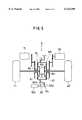
- FIG. 2is a skeleton diagram showing the construction of the difference rotation generating apparatus
- FIG. 3is a schematic diagram showing a condition in which a slip angle has occurred
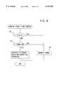
- FIG. 4is a flow chart showing the contents of running stabilizing control.
- FIG. 5is a skeleton diagram showing another embodiment of the difference rotation generating apparatus.
- FIG. 1shows a front-wheel-drive vehicle in which left and right front wheels 3L, 3R are driven by an engine 1 via a transmission 2. Between left and right rear wheels 4L, 4R which are idler wheels, there is disposed a difference rotation generating apparatus 5.
- the difference rotation generating apparatus 5is provided, as shown in FIG. 2, with a pair of left and right differential gears 6L, 6R and an electric motor 7 which is made up of a small-sized DC brush motor to be used as a starter or the like.
- Each of the differential gears 6L, 6Ris constituted by a bevel gear type of differential gear which is made up by rotatably supporting, on a differential gear case 6a, a pair of left and right side gears 6b, 6c which are made up of bevel gears, as well as pinions 6d which are engaged with both the side gears 6b, 6c.
- the first side gears 6b, 6bwhich lie on an axially inner side of both the differential gears 6L, 6R are coupled to each other.
- the electric motor 7is connected to the differential gear case 6a of one, e.g., the differential gear 6R on the right side, of both the differential gears 6L, 6R.
- the right rear wheel 4Ris connected to the axially outside second side gear 6c of the differential gear 6R.
- the differential gear case 6a of the differential gear 6L on the left sideis fixed to the casing 5a of the difference rotation generating apparatus 5.
- the left rear wheel 4Lis selectively connected through a switching means 8 to the first side gear 6b on an axially inner side of the differential gear 6L and the second side gear 6c on an axially outer side thereof.
- the switching means 8is constituted by a movable dog 8a which is connected to the left rear wheel 4L and which is axially movable back and forth, and stationary dogs 8b, 8c which are respectively mounted on the first side gear 6b and the second side gear 6c of the differential gear 6L on the left side.
- the movable dog 8ais moved back and forth by means of a solenoid 8d so as to be selectively engaged with both the stationary dogs 8b, 8c.
- the left rear wheel 4LWhen the left rear wheel 4L is connected to the first side gear 6b of the differential gear 6L on the left side, the left rear wheel 4L becomes a state of being directly connected to the first side gear 6b of the differential gear 6R on the right side.
- the differential gear case 6a of the differential gear 6R on the right sideis rotated by the electric motor 7, both the left and right rear wheels 6L, 6R are driven for rotation in the same direction.
- the first side gear 6bis rotated together with the left rear wheel 4L at the same rotational speed in the opposite direction.
- the differential gear case 6a of the differential gear 6R on the right sidewill not rotate.
- the second side gear 6c of the differential gear 6R on the right sideis rotated with increasing speed relative to the first side gear 6b.
- the right rear wheel 4Ris thus rotated with increasing speed than is the left rear wheel 4L.
- the output torque of the electric motor 7is thus transmitted to the right rear wheel 4R as a driving force and to the left rear wheel 4L as a braking force, whereby a yawing moment toward the left is generated.
- the differential gear case 6a of the differential gear 6R on the right sideis rotated by the electric motor 7 in the reverse direction
- the first side gear 6b of the differential gear 6R on the right sideis rotated with increasing speed relative to the second side gear 6c.
- the left rear wheel 4Lis thus rotated with increasing speed than is the right rear wheel 4R.
- the output torque of the electric motor 7is thus transmitted to the left rear wheel 4L as a driving force and to the right rear wheel 4R as a braking force, whereby a yawing moment toward the right is generated.
- the vehiclehas mounted thereon a controller 10 having a control section 10a which controls the brake 9 of each of the wheels 3L, 3R, 4L, 4R and a control section 10b which controls the electric motor 7 and the switching means 8 of the difference rotation generating apparatus 5.
- the controller 10there are inputted the following signals, i.e., signals from sensors 11L, 11R which detect the rotational speeds of the left and right front wheels 3L, 3R, sensors 12L, 12R which detect the rotational speeds of the left and right rear wheels 4L, 4R, a brake switch 13 which is switched on by pressing on a brake pedal, an accelerator pedal switch 14, a neutral switch 15 which detects whether the transmission 2 is in the neutral state of not, a steering angle sensor 16, and a yaw rate sensor 17.
- the starting assistance control, the cornering assistance control, and the running stabilizing controlare performed as described hereinbelow.
- the starting assistance controlis performed in the following manner. Namely, by making the switching means 8 to a state in which the left rear wheel 4L is connected to the first side gear 6b of the differential gear 6L on the left side, the electric motor 7 is rotated in the normal direction or in the reverse direction. The left and right rear wheels are thus rotated either in the normal direction or in the reverse direction, whereby the starting assistance for forward running or reverse running is performed.
- the following four conditionsi.e., that the brake switch 13 is switched off, that the accelerator switch 14 is switched on, that the transmission 2 is in the non-neutral state, and that the vehicle speed (rear wheel speed) is below a predetermined value, a judgement is made that the vehicle is in a state ready to start.
- the starting assistance controlis performed.
- the switching means 8is switched and held to the state in which the left rear wheel 4L is connected to the second side gear 6c of the differential gear 6L on the left side, and the driving of the electric motor 7 is once stopped.
- the cornering assistance controlis performed at the time of turning or cornering of the vehicle.
- the electric motor 7is driven so that the rear wheel on the outer side, between the left and right rear wheels 4L, 4R, is rotated with increasing speed.
- a yawing moment in the cornering directionis generated by giving a driving force to the outer wheel and a braking force to the inner wheel, thereby assisting the cornering movement of the vehicle.
- the running stabilizing controlis performed when the vehicle has inclined relative to the running direction as shown in FIG. 3.
- the contents of the controlare as shown in FIG. 4. An explanation will be made in more detail about it.
- a discriminationis made first as to whether the slip angle ⁇ of the vehicle is above a predetermined value ⁇ s or not (S1).
- the slip angle ⁇is computed by a comparison between a reference yaw rate of the vehicle which is computed by the vehicle speed and the steering angle, and the actual yaw rate which is detected by the yaw rate sensor 17.
- a discriminationis made as to whether the accelerator switch 14 has been switched on as a result of the pressing on of the accelerator pedal, i.e., whether the driving condition of the vehicle is in a so-called power-on state in which the front wheels 3L, 3R are positively driven by the engine 1 (S2).
- the accelerator switch 14is switched off, i.e., when the vehicle is in a so-called power-off state in which the positive driving of the front wheels 3L, 3R by the engine 1 is stopped, the left and right brakes 9 are independently operated so that the yawing moment to reduce the slip angle ⁇ can be generated (S3).
- the brakes 9 of the right front and rear wheels 3R, 4Rare operated. If the slip angle ⁇ shows an inclination toward the right, the brakes 9 of the left front and rear wheels 3L, 4L are operated. Also when ⁇ s, the left and right brakes 9 are operated independently.
- the difference rotation generating apparatus 5is operated to thereby generate the yawing moment to reduce the slip angle ⁇ .
- the slip angle ⁇shows an inclination toward the left, the electric motor 7 is driven in the reverse direction.
- the left rear wheel 4Lis thus accelerated to thereby generate the yawing moment toward the right. If the slip angle ⁇ shows an inclination toward the right, the electric motor 7 is driven in the normal direction. The right rear wheel 4R is thus accelerated to thereby generate the yawing moment toward the left.
- the difference rotation generating apparatus 5is not limited to the above-described embodiment. As shown in FIG. 5, an arrangement may also be made such that there are provided a pair of left and right differential gears 6L, 6R and a pair of left and right electric motors 7L, 7R.
- each of the differential gears 6L, 6Ris constituted by a planetary type of differential gear having a sun gear 60, a ring gear 61, and a carrier 63 which rotatably supports a planetary pinion 62 which is engaged with both the gears 60, 61.
- Left and right rear wheels 4L, 4Rare respectively connected to the carriers 63, 63 of the left and right differential gears 6L, 6R.
- the left and right electric motors 7L, 7Rare connected to the sun gears 60, 60 of the left and right differential gears 6L, 6R.
- the ring gears 61, 61 of both the left and right differential gears 6L, 6Rare connected to each other.
- a brake means 80 to restrain the rotation of this ring gear 61is provided.
- the brake means 80is constituted by a movable dog 80a which is prevented from rotating relative to the ring gear 61 and which is axially movable back and forth, as well as a stationary dog 80b which is fixed to the casing 5a of the difference rotation generating apparatus 5.
- the movable dog 80ais engaged with, and disengaged from, the stationary dog 80b by the back and forth movement by means of a solenoid 80c. The restraining and releasing of the ring gear 61 are thus performed.
- the ring gearfunctions as a reaction force receiving member.
- the carriers 63, 63 of both the differential gears 6L, 6Rare rotated in the normal or reverse direction.
- the left and right rear wheels 4L, 4Rare thus driven for rotation in the same direction.
- both the electric motors 7L, 7Rare driven in the opposite directions
- the left electric motor 7Lis rotated in the normal direction and the right electric motor 7R is rotated in the reverse direction
- the sun gear 60 of the differential gear 6L on the left sideis rotated in the normal direction and its carrier 63 is rotated in the normal direction relative to the ring gear 61.
- the sun gear 60 of the differential gear 6R on the right sideis rotated in the reverse direction and its carrier 63 is rotated in the reverse direction relative to the ring gear 61.
- the carrier 63 of the differential gear 6L on the left sidei.e., the left rear wheel 4L is accelerated
- the carrier 63 of the differential gear 6R on the right sidei.e., the right rear wheel 4R is decelerated.
- a driving forceis applied to the left rear wheel 4L and a braking force is applied to the right rear wheel 4R, whereby a yawing moment toward the right is generated.
- the starting assistance control and the cornering assistance control, and the running stabilizing controlcan be performed in the same manner as the above-described embodiment.
- the following arrangementmay also be employed. Namely, by deleting the switching means 8 in the embodiment shown in FIG. 2, the left rear wheel 4L is constantly connected to the second side gear 6c of the left differential gear 6L. Further, by deleting the braking means 80 in the embodiment shown in FIG. 5, the ring gear 81 is made constantly free to thereby perform only the cornering assistance control and the running stabilizing control.
- the frequency of operating the brakes in a power-on statebecomes small. Therefore, the brakes can be prevented from being impaired in durability in the running stabilizing control, and the driving comfort at the time of acceleration can also be prevented from being impaired.
Landscapes
- Engineering & Computer Science (AREA)
- Transportation (AREA)
- Mechanical Engineering (AREA)
- Retarders (AREA)
- Regulating Braking Force (AREA)
- Arrangement And Mounting Of Devices That Control Transmission Of Motive Force (AREA)
- Electric Propulsion And Braking For Vehicles (AREA)
- Motor Power Transmission Devices (AREA)
- Hydraulic Control Valves For Brake Systems (AREA)
Abstract
Description
Claims (2)
Applications Claiming Priority (2)
| Application Number | Priority Date | Filing Date | Title |
|---|---|---|---|
| JP25346897AJP3419659B2 (en) | 1997-09-18 | 1997-09-18 | Vehicle running stabilizer |
| JP9-253468 | 1997-09-18 |
Publications (1)
| Publication Number | Publication Date |
|---|---|
| US6123398Atrue US6123398A (en) | 2000-09-26 |
Family
ID=17251813
Family Applications (1)
| Application Number | Title | Priority Date | Filing Date |
|---|---|---|---|
| US09/154,166Expired - LifetimeUS6123398A (en) | 1997-09-18 | 1998-09-16 | Running stablizing apparatus to be mounted on vehicle |
Country Status (7)
| Country | Link |
|---|---|
| US (1) | US6123398A (en) |
| JP (1) | JP3419659B2 (en) |
| KR (1) | KR100505077B1 (en) |
| CA (1) | CA2247185C (en) |
| DE (1) | DE19841108B4 (en) |
| FR (1) | FR2768375B1 (en) |
| GB (1) | GB2332719B (en) |
Cited By (96)
| Publication number | Priority date | Publication date | Assignee | Title |
|---|---|---|---|---|
| US6575282B2 (en)* | 2000-02-10 | 2003-06-10 | Borgwarner, Inc. | Yaw damper for a two wheel drive motor vehicle |
| US20040135527A1 (en)* | 2003-01-15 | 2004-07-15 | Honda Motor Co., Ltd. | Control apparatus for hybrid vehicles |
| US20050252186A1 (en)* | 2004-05-10 | 2005-11-17 | Comac S.P.A. | Self-propelled vehicle particularly for making turns with tight turning radii |
| US20070138887A1 (en)* | 2005-12-14 | 2007-06-21 | Andrea Tonoli | Electromechanical differential module for a wheeled vehicle and a wheeled vehicle equipped with such an electromechanical differential module |
| US20080191650A1 (en)* | 2007-02-09 | 2008-08-14 | Arun Kumar Seksaria | Brake Responsive Vehicle Electric Drive System |
| US20090014226A1 (en)* | 2007-07-11 | 2009-01-15 | Gm Global Technology Operations, Inc. | Torque Differential Modification of a Non-Driven Axle |
| CN102348570A (en)* | 2009-01-16 | 2012-02-08 | 通用汽车环球科技运作有限责任公司 | Drive mechanism that selectively switches drive between propulsion and torque vectoring modes |
| US8127873B1 (en)* | 2007-06-26 | 2012-03-06 | Walsh Robert D | Electric powered automobile/wheel turbine motor |
| CN104709068A (en)* | 2015-03-12 | 2015-06-17 | 济南大学 | Automobile using novel axles |
| US9400502B2 (en) | 2004-09-13 | 2016-07-26 | Deka Products Limited Partnership | Control of a personal transporter based on user position |
| US9545963B2 (en) | 2002-07-12 | 2017-01-17 | DEKA Products Limited Partnership LLP | Control of a transporter based on attitude |
| US10220843B2 (en) | 2016-02-23 | 2019-03-05 | Deka Products Limited Partnership | Mobility device control system |
| US10226376B2 (en) | 2014-03-19 | 2019-03-12 | Purewick Corporation | Apparatus and methods for receiving discharged urine |
| CN109501782A (en)* | 2018-12-12 | 2019-03-22 | 三汽车制造有限公司 | The single brake type wheel undercarriage in left and right and unmanned platform truck |
| USD846452S1 (en) | 2017-05-20 | 2019-04-23 | Deka Products Limited Partnership | Display housing |
| US10376407B2 (en) | 2016-08-16 | 2019-08-13 | Purewick Corporation | Using wicking material to collect urine from a male for transport |
| US10376406B2 (en) | 2016-07-27 | 2019-08-13 | Purewick Corporation | Male urine collection device using wicking material |
| US10390989B2 (en) | 2014-03-19 | 2019-08-27 | Purewick Corporation | Apparatus and methods for receiving discharged urine |
| WO2019212951A1 (en) | 2018-05-01 | 2019-11-07 | Purewick Corporation | Fluid collection devices, systems, and methods |
| WO2019212956A1 (en) | 2018-05-02 | 2019-11-07 | Purewick Corporation | Fluid collection devices, systems, and methods |
| WO2019212952A1 (en) | 2018-05-01 | 2019-11-07 | Purewick Corporation | Fluid collection devices, related systems, and related methods |
| WO2019212950A1 (en) | 2018-05-01 | 2019-11-07 | Purewick Corporation | Fluid collection devices, related systems, and related methods |
| WO2019212955A1 (en) | 2018-05-01 | 2019-11-07 | Purewick Corporation | Fluid collection devices and methods of using the same |
| WO2019212949A1 (en) | 2018-05-01 | 2019-11-07 | Purewick Corporation | Fluid collection devices, systems, and methods |
| WO2019212954A1 (en) | 2018-05-01 | 2019-11-07 | Purewick Corporation | Fluid collection garments |
| US10802495B2 (en) | 2016-04-14 | 2020-10-13 | Deka Products Limited Partnership | User control device for a transporter |
| WO2020242559A1 (en) | 2019-05-29 | 2020-12-03 | Purewick Corporation | Fluid collection devices and systems having a fluid impermeable barrier with a selectively minimal hardness, thickness, and/or modulus of elasticity |
| WO2020256865A1 (en) | 2019-06-21 | 2020-12-24 | Purewick Corporation | Fluid collection devices including a base securement area, and related systems and methods |
| WO2021007345A1 (en) | 2019-07-11 | 2021-01-14 | Purewick Corporation | Fluid collection devices, systems and methods |
| WO2021007349A1 (en) | 2019-07-11 | 2021-01-14 | Purewick Corporation | Fluid collection devices, systems, and methods |
| WO2021016026A1 (en) | 2019-07-19 | 2021-01-28 | Purewick Corporation | Fluid collection devices including at least one shape memory material |
| US10908045B2 (en) | 2016-02-23 | 2021-02-02 | Deka Products Limited Partnership | Mobility device |
| US10926756B2 (en) | 2016-02-23 | 2021-02-23 | Deka Products Limited Partnership | Mobility device |
| US10952889B2 (en) | 2016-06-02 | 2021-03-23 | Purewick Corporation | Using wicking material to collect liquid for transport |
| USD915248S1 (en) | 2017-05-20 | 2021-04-06 | Deka Products Limited Partnership | Set of toggles |
| US10973678B2 (en) | 2016-07-27 | 2021-04-13 | Purewick Corporation | Apparatus and methods for receiving discharged urine |
| US11090183B2 (en) | 2014-11-25 | 2021-08-17 | Purewick Corporation | Container for collecting liquid for transport |
| USD928946S1 (en) | 2016-06-02 | 2021-08-24 | Purewick Corporation | Urine receiving apparatus |
| USD929578S1 (en) | 2019-06-06 | 2021-08-31 | Purewick Corporation | Urine collection assembly |
| WO2021188817A1 (en) | 2020-03-19 | 2021-09-23 | Purewick Corporation | Fluid collection assemblies including one or more movement enhancing features |
| WO2021207621A1 (en) | 2020-04-10 | 2021-10-14 | Purewick Corporation | Fluid collection assemblies including one or more leak prevention features |
| WO2021211799A1 (en) | 2020-04-17 | 2021-10-21 | Purewick Corporation | Fluid collection assemblies including a vaginal implants |
| WO2021211801A1 (en) | 2020-04-17 | 2021-10-21 | Purewick Corporation | Fluid collection assemblies including a fluid impermeable barrier having a sump and a base |
| WO2021211729A1 (en) | 2020-04-17 | 2021-10-21 | Purewick Corporation | Fluid collection devices, systems, and methods securing a protruding portion in position for use |
| WO2021216419A1 (en) | 2020-04-20 | 2021-10-28 | Purewick Corporation | Fluid collection devices, systems, and methods utilizing retention components |
| WO2022006256A1 (en) | 2020-07-02 | 2022-01-06 | Purewick Corporation | Male fluid collection assemblies and systems, methods of using, and methods of manufacturing the same |
| WO2022029662A1 (en) | 2020-08-05 | 2022-02-10 | Purewick Corporation | Fluid collection devices and systems including an adhesive securement feature, and methods of use |
| WO2022031943A1 (en) | 2020-08-06 | 2022-02-10 | Purewick Corporation | A fluid collection system including a garment and a fluid collection device |
| WO2022051360A1 (en) | 2020-09-03 | 2022-03-10 | Purewick Corporation | Fluid collection devices, systems and methods |
| WO2022055957A1 (en) | 2020-09-09 | 2022-03-17 | Purewick Corporation | Fluid collection devices, systems, and methods |
| WO2022066704A1 (en) | 2020-09-23 | 2022-03-31 | Purewick Corporation | Securement systems and methods for fluid collection assemblies |
| WO2022115692A1 (en) | 2020-11-30 | 2022-06-02 | Purewick Corporation | Fluid collection devices with anatomical fit cross-reference to related applications |
| US11376152B2 (en) | 2014-03-19 | 2022-07-05 | Purewick Corporation | Apparatus and methods for receiving discharged urine |
| US11382786B2 (en)* | 2014-03-19 | 2022-07-12 | Purewick Corporation | Apparatus and methods for receiving discharged urine |
| WO2022159392A1 (en) | 2021-01-19 | 2022-07-28 | Purewick Corporation | Variable fit fluid collection devices, systems, and methods |
| US11399995B2 (en) | 2016-02-23 | 2022-08-02 | Deka Products Limited Partnership | Mobility device |
| WO2022216776A1 (en) | 2021-04-09 | 2022-10-13 | Purewick Corporation | Conduits including at least one conduit porous material |
| USD967409S1 (en) | 2020-07-15 | 2022-10-18 | Purewick Corporation | Urine collection apparatus cover |
| US20220331147A1 (en)* | 2021-04-19 | 2022-10-20 | Lyv Life Inc. DBA Cora | Menstrual disc and methods of use |
| WO2022271959A1 (en) | 2021-06-25 | 2022-12-29 | Purewick Corporation | Fluid collection assemblies exhibiting a relatively thin shape |
| US20230049924A1 (en)* | 2020-01-30 | 2023-02-16 | Purewick Corporation | Fluid coolection assemblies including a skirt |
| US11681293B2 (en) | 2018-06-07 | 2023-06-20 | Deka Products Limited Partnership | System and method for distributed utility service execution |
| WO2023146529A1 (en) | 2022-01-28 | 2023-08-03 | Purewick Corporation | Male fluid collection assemblies and systems, methods of using, and methods of manufacturing the same |
| WO2023154390A1 (en) | 2022-02-09 | 2023-08-17 | Purewick Corporation | Fluid collection systems including an on-demand pump, and related methods |
| US20230255815A1 (en)* | 2021-02-26 | 2023-08-17 | Purewick Corporation | Fluid collection devices having a sump between a tube opening and a barrier, and related systems and methods |
| US11801186B2 (en) | 2020-09-10 | 2023-10-31 | Purewick Corporation | Urine storage container handle and lid accessories |
| US11938054B2 (en) | 2021-03-10 | 2024-03-26 | Purewick Corporation | Bodily waste and fluid collection with sacral pad |
| US12029677B2 (en) | 2021-04-06 | 2024-07-09 | Purewick Corporation | Fluid collection devices having a collection bag, and related systems and methods |
| US12042423B2 (en) | 2020-10-07 | 2024-07-23 | Purewick Corporation | Fluid collection systems including at least one tensioning element |
| US12048644B2 (en) | 2020-11-03 | 2024-07-30 | Purewick Corporation | Apparatus for receiving discharged urine |
| US12048643B2 (en) | 2020-05-27 | 2024-07-30 | Purewick Corporation | Fluid collection assemblies including at least one inflation device and methods and systems of using the same |
| US12070432B2 (en) | 2020-11-11 | 2024-08-27 | Purewick Corporation | Urine collection system including a flow meter and related methods |
| WO2024215322A1 (en) | 2023-04-13 | 2024-10-17 | Purewick Corporation | Fluid collection device holders, and related systems and methods |
| USD1047785S1 (en) | 2017-05-20 | 2024-10-22 | Deka Products Limited Partnership | Toggle control device |
| US12150885B2 (en) | 2021-05-26 | 2024-11-26 | Purewick Corporation | Fluid collection system including a cleaning system and methods |
| US12156792B2 (en) | 2020-09-10 | 2024-12-03 | Purewick Corporation | Fluid collection assemblies including at least one inflation device |
| WO2024253655A1 (en) | 2023-06-08 | 2024-12-12 | Purewick Corporation | Fluid collection devices having a fluid permeable body with a hydrophilic material secured to a non-woven material, and methods of manufacture |
| US12178735B2 (en) | 2021-02-09 | 2024-12-31 | Purewick Corporation | Noise reduction for a urine suction system |
| US12208031B2 (en) | 2020-10-21 | 2025-01-28 | Purewick Corporation | Adapters for fluid collection devices |
| WO2025038087A1 (en) | 2023-08-16 | 2025-02-20 | Purewick Corporation | Male fluid collection assemblies and systems, methods of using, and methods of manufacturing the same |
| WO2025038088A1 (en) | 2023-08-16 | 2025-02-20 | Purewick Corporation | Male fluid collection assemblies and systems, methods of using, and methods of manufacturing the same |
| US12233003B2 (en) | 2021-04-29 | 2025-02-25 | Purewick Corporation | Fluid collection assemblies including at least one length adjusting feature |
| WO2025048789A1 (en) | 2023-08-29 | 2025-03-06 | Purewick Corporation | Fluid collection devices with structural support |
| WO2025048822A1 (en) | 2023-08-31 | 2025-03-06 | Purewick Corporation | Fluid collection devices with segmented porous material |
| WO2025048790A1 (en) | 2023-08-29 | 2025-03-06 | Purewick Corporation | Fluid collection device having a conduit including a flow retainer |
| US12245967B2 (en) | 2020-11-18 | 2025-03-11 | Purewick Corporation | Fluid collection assemblies including an adjustable spine |
| US12251333B2 (en) | 2021-05-21 | 2025-03-18 | Purewick Corporation | Fluid collection assemblies including at least one inflation device and methods and systems of using the same |
| US12257173B2 (en) | 2017-01-31 | 2025-03-25 | Purewick Corporation | Apparatus and methods for receiving discharged urine |
| US12257174B2 (en) | 2020-10-21 | 2025-03-25 | Purewick Corporation | Fluid collection assemblies including at least one of a protrusion or at least one expandable material |
| US12268627B2 (en) | 2021-01-06 | 2025-04-08 | Purewick Corporation | Fluid collection assemblies including at least one securement body |
| WO2025085080A1 (en) | 2023-10-18 | 2025-04-24 | Purewick Corporation | Male external catheter device having a body portion and a bag portion, and related systems and methods of use of the catheter device |
| WO2025110991A1 (en) | 2023-11-21 | 2025-05-30 | Purewick Corporation | Fluid collection devices including a coextruded shape memory material |
| US12324767B2 (en) | 2021-05-24 | 2025-06-10 | Purewick Corporation | Fluid collection assembly including a customizable external support and related methods |
| US12350190B2 (en) | 2020-01-03 | 2025-07-08 | Purewick Corporation | Urine collection devices having a relatively wide portion and an elongated portion and related methods |
| US12350187B2 (en) | 2020-08-11 | 2025-07-08 | Purewick Corporation | Fluid collection assemblies defining waist and leg openings |
| US12440401B2 (en) | 2024-05-22 | 2025-10-14 | Deka Products Limited Partnership | Mobility device |
Families Citing this family (5)
| Publication number | Priority date | Publication date | Assignee | Title |
|---|---|---|---|---|
| GB2348253B (en)* | 1999-03-26 | 2003-04-02 | Rover Group | Transmission differential assembly with yaw control |
| JP4759946B2 (en)* | 2004-05-10 | 2011-08-31 | 株式会社ジェイテクト | Left and right wheel drive device, front and rear wheel drive device and control method thereof |
| JP4637136B2 (en) | 2007-05-23 | 2011-02-23 | 本田技研工業株式会社 | Power equipment |
| GB2466968A (en)* | 2009-01-16 | 2010-07-21 | Gm Global Tech Operations Inc | Hybrid vehicle with auxiliary drive member providing an offset torque |
| JP7327098B2 (en)* | 2019-11-15 | 2023-08-16 | 三菱自動車工業株式会社 | drive wheel drive |
Citations (6)
| Publication number | Priority date | Publication date | Assignee | Title |
|---|---|---|---|---|
| US3720863A (en)* | 1969-08-27 | 1973-03-13 | Allis Chalmers | Electrically driven vehicle steered by control of power and speed of tractive elements |
| US5328255A (en)* | 1989-10-09 | 1994-07-12 | Robert Bosch Gmbh | Wheel slip control system |
| US5645326A (en)* | 1995-06-30 | 1997-07-08 | Mitsubishi Jidosha Kogyo Kabushiki Kaisha | Turn control apparatus for a vehicle |
| US5839535A (en)* | 1995-05-01 | 1998-11-24 | Honda Giken Koygo Kabushiki Kaisha | Front wheel- and rear wheel-drive vehicle and apparatus for detecting coefficient of friction on road surface |
| US6024182A (en)* | 1995-09-11 | 2000-02-15 | Honda Giken Kogyo Kabushiki Kaisha | Coupling device between left and right wheels of vehicle |
| US6033040A (en)* | 1996-12-04 | 2000-03-07 | Honda Giken Kogyo Kabushiki Kaisha | Yaw moment control system in vehicle |
Family Cites Families (2)
| Publication number | Priority date | Publication date | Assignee | Title |
|---|---|---|---|---|
| DE3939069C2 (en)* | 1989-11-25 | 2002-07-04 | Bosch Gmbh Robert | motor vehicle |
| CA2484819C (en)* | 1995-09-11 | 2005-09-13 | Honda Giken Kogyo Kabushiki Kaisha | Coupling device between left and right wheels of vehicle |
- 1997
- 1997-09-18JPJP25346897Apatent/JP3419659B2/ennot_activeExpired - Fee Related
- 1998
- 1998-09-09DEDE19841108Apatent/DE19841108B4/ennot_activeExpired - Fee Related
- 1998-09-15CACA002247185Apatent/CA2247185C/ennot_activeExpired - Fee Related
- 1998-09-16GBGB9820186Apatent/GB2332719B/ennot_activeExpired - Fee Related
- 1998-09-16USUS09/154,166patent/US6123398A/ennot_activeExpired - Lifetime
- 1998-09-16KRKR10-1998-0038296Apatent/KR100505077B1/ennot_activeExpired - Fee Related
- 1998-09-17FRFR9811632Apatent/FR2768375B1/ennot_activeExpired - Fee Related
Patent Citations (6)
| Publication number | Priority date | Publication date | Assignee | Title |
|---|---|---|---|---|
| US3720863A (en)* | 1969-08-27 | 1973-03-13 | Allis Chalmers | Electrically driven vehicle steered by control of power and speed of tractive elements |
| US5328255A (en)* | 1989-10-09 | 1994-07-12 | Robert Bosch Gmbh | Wheel slip control system |
| US5839535A (en)* | 1995-05-01 | 1998-11-24 | Honda Giken Koygo Kabushiki Kaisha | Front wheel- and rear wheel-drive vehicle and apparatus for detecting coefficient of friction on road surface |
| US5645326A (en)* | 1995-06-30 | 1997-07-08 | Mitsubishi Jidosha Kogyo Kabushiki Kaisha | Turn control apparatus for a vehicle |
| US6024182A (en)* | 1995-09-11 | 2000-02-15 | Honda Giken Kogyo Kabushiki Kaisha | Coupling device between left and right wheels of vehicle |
| US6033040A (en)* | 1996-12-04 | 2000-03-07 | Honda Giken Kogyo Kabushiki Kaisha | Yaw moment control system in vehicle |
Non-Patent Citations (2)
| Title |
|---|
| Bosch Automotive Handbook, 3rd edition Copyright 1993 pp. 336 339.* |
| Bosch Automotive Handbook, 3rd edition Copyright 1993 pp. 336-339. |
Cited By (163)
| Publication number | Priority date | Publication date | Assignee | Title |
|---|---|---|---|---|
| US9411340B2 (en) | 1999-06-04 | 2016-08-09 | Deka Products Limited Partnership | Control of a personal transporter based on user position |
| US10118661B2 (en) | 1999-06-04 | 2018-11-06 | Deka Products Limited Partnership | Control of a personal transporter based on user position |
| US9442491B2 (en) | 1999-06-04 | 2016-09-13 | Deka Products Limited Partnership | Control of a personal transporter based on user position |
| US9442492B2 (en) | 1999-06-04 | 2016-09-13 | Deka Products Limited Partnership | Control of a personal transporter based on user position |
| US9411336B2 (en) | 1999-06-04 | 2016-08-09 | Deka Products Limited Partnership | Control of a personal transporter based on user position |
| US6575282B2 (en)* | 2000-02-10 | 2003-06-10 | Borgwarner, Inc. | Yaw damper for a two wheel drive motor vehicle |
| US11648995B2 (en) | 2002-07-12 | 2023-05-16 | Deka Products Limited Partnership | Control of a transporter based on attitude |
| US10227098B2 (en) | 2002-07-12 | 2019-03-12 | Deka Products Limited Partnership | Control of a transporter based on attitude |
| US9545963B2 (en) | 2002-07-12 | 2017-01-17 | DEKA Products Limited Partnership LLP | Control of a transporter based on attitude |
| US20040135527A1 (en)* | 2003-01-15 | 2004-07-15 | Honda Motor Co., Ltd. | Control apparatus for hybrid vehicles |
| US20050252186A1 (en)* | 2004-05-10 | 2005-11-17 | Comac S.P.A. | Self-propelled vehicle particularly for making turns with tight turning radii |
| US7328758B2 (en)* | 2004-05-10 | 2008-02-12 | Comac S.P.A. | Self-propelled vehicle particularly for making turns with tight turning radii |
| US9400502B2 (en) | 2004-09-13 | 2016-07-26 | Deka Products Limited Partnership | Control of a personal transporter based on user position |
| US9442486B2 (en) | 2004-09-13 | 2016-09-13 | Deka Products Limited Partnership | Control of a personal transporter based on user position |
| US10370052B2 (en) | 2004-09-13 | 2019-08-06 | Deka Products Limited Partnership | Control of a personal transporter based on user position |
| US9411339B2 (en) | 2004-09-13 | 2016-08-09 | Deka Products Limited Partnership | Control of a personal transporter based on user position |
| US9429955B2 (en) | 2004-09-13 | 2016-08-30 | Deka Products Limited Partnership | Control of a personal transporter based on user position |
| US9983587B2 (en) | 2004-09-13 | 2018-05-29 | Deka Products Limited Partnership | Control of a personal transporter based on user position |
| US9529365B2 (en) | 2004-09-13 | 2016-12-27 | Deka Products Limited Partnership | Control of a personal transporter based on user position |
| US9459627B2 (en) | 2004-09-13 | 2016-10-04 | Deka Products Limited Partership | Control of a personal transporter based on user position |
| US20070138887A1 (en)* | 2005-12-14 | 2007-06-21 | Andrea Tonoli | Electromechanical differential module for a wheeled vehicle and a wheeled vehicle equipped with such an electromechanical differential module |
| US7466091B2 (en)* | 2007-02-09 | 2008-12-16 | Deere & Company | Brake responsive vehicle electric drive system |
| US20080191650A1 (en)* | 2007-02-09 | 2008-08-14 | Arun Kumar Seksaria | Brake Responsive Vehicle Electric Drive System |
| US8127873B1 (en)* | 2007-06-26 | 2012-03-06 | Walsh Robert D | Electric powered automobile/wheel turbine motor |
| US20090014226A1 (en)* | 2007-07-11 | 2009-01-15 | Gm Global Technology Operations, Inc. | Torque Differential Modification of a Non-Driven Axle |
| CN102348570A (en)* | 2009-01-16 | 2012-02-08 | 通用汽车环球科技运作有限责任公司 | Drive mechanism that selectively switches drive between propulsion and torque vectoring modes |
| CN102348570B (en)* | 2009-01-16 | 2015-06-24 | 通用汽车环球科技运作有限责任公司 | Drive mechanism that selectively switches drive between propulsion and torque vectoring modes |
| US12161579B2 (en) | 2014-03-19 | 2024-12-10 | Purewick Corporation | Apparatus and methods for receiving discharged urine |
| US12171685B2 (en) | 2014-03-19 | 2024-12-24 | Purewick Corporation | Apparatus and methods for receiving discharged urine |
| US11382786B2 (en)* | 2014-03-19 | 2022-07-12 | Purewick Corporation | Apparatus and methods for receiving discharged urine |
| US10226376B2 (en) | 2014-03-19 | 2019-03-12 | Purewick Corporation | Apparatus and methods for receiving discharged urine |
| US11376152B2 (en) | 2014-03-19 | 2022-07-05 | Purewick Corporation | Apparatus and methods for receiving discharged urine |
| US12121468B2 (en) | 2014-03-19 | 2024-10-22 | Purewick Corporation | Apparatus and methods for receiving discharged urine |
| US10390989B2 (en) | 2014-03-19 | 2019-08-27 | Purewick Corporation | Apparatus and methods for receiving discharged urine |
| US12138196B2 (en) | 2014-03-19 | 2024-11-12 | Purewick Corporation | Apparatus and methods for receiving discharged urine |
| US11806266B2 (en) | 2014-03-19 | 2023-11-07 | Purewick Corporation | Apparatus and methods for receiving discharged urine |
| US12239567B2 (en) | 2014-03-19 | 2025-03-04 | Purewick Corporation | Apparatus and methods for receiving discharged urine |
| US12324765B2 (en) | 2014-03-19 | 2025-06-10 | Purewick Corporation | Apparatus and methods for receiving discharged urine |
| US11090183B2 (en) | 2014-11-25 | 2021-08-17 | Purewick Corporation | Container for collecting liquid for transport |
| CN104709068A (en)* | 2015-03-12 | 2015-06-17 | 济南大学 | Automobile using novel axles |
| US11794722B2 (en) | 2016-02-23 | 2023-10-24 | Deka Products Limited Partnership | Mobility device |
| US12023285B2 (en) | 2016-02-23 | 2024-07-02 | Deka Products Limited Partnership | Mobility device |
| US10752243B2 (en) | 2016-02-23 | 2020-08-25 | Deka Products Limited Partnership | Mobility device control system |
| US12240440B2 (en) | 2016-02-23 | 2025-03-04 | Deka Products Limited Partnership | Mobility device |
| US11679044B2 (en) | 2016-02-23 | 2023-06-20 | Deka Products Limited Partnership | Mobility device |
| US10926756B2 (en) | 2016-02-23 | 2021-02-23 | Deka Products Limited Partnership | Mobility device |
| US10220843B2 (en) | 2016-02-23 | 2019-03-05 | Deka Products Limited Partnership | Mobility device control system |
| US11399995B2 (en) | 2016-02-23 | 2022-08-02 | Deka Products Limited Partnership | Mobility device |
| US10908045B2 (en) | 2016-02-23 | 2021-02-02 | Deka Products Limited Partnership | Mobility device |
| US12117842B2 (en) | 2016-04-14 | 2024-10-15 | Deka Products Limited Partnership | User control device for a transporter |
| US10802495B2 (en) | 2016-04-14 | 2020-10-13 | Deka Products Limited Partnership | User control device for a transporter |
| US11720115B2 (en) | 2016-04-14 | 2023-08-08 | Deka Products Limited Partnership | User control device for a transporter |
| US10952889B2 (en) | 2016-06-02 | 2021-03-23 | Purewick Corporation | Using wicking material to collect liquid for transport |
| USD928946S1 (en) | 2016-06-02 | 2021-08-24 | Purewick Corporation | Urine receiving apparatus |
| US12193962B2 (en) | 2016-06-02 | 2025-01-14 | Purewick Corporation | Using wicking material to collect liquid for transport |
| US10376406B2 (en) | 2016-07-27 | 2019-08-13 | Purewick Corporation | Male urine collection device using wicking material |
| US12029678B2 (en) | 2016-07-27 | 2024-07-09 | Purewick Corporation | Male urine collection device using wicking material |
| US10973678B2 (en) | 2016-07-27 | 2021-04-13 | Purewick Corporation | Apparatus and methods for receiving discharged urine |
| US11628086B2 (en) | 2016-07-27 | 2023-04-18 | Purewick Corporation | Apparatus and methods for receiving discharged urine |
| US10376407B2 (en) | 2016-08-16 | 2019-08-13 | Purewick Corporation | Using wicking material to collect urine from a male for transport |
| US12257173B2 (en) | 2017-01-31 | 2025-03-25 | Purewick Corporation | Apparatus and methods for receiving discharged urine |
| USD915248S1 (en) | 2017-05-20 | 2021-04-06 | Deka Products Limited Partnership | Set of toggles |
| USD876994S1 (en) | 2017-05-20 | 2020-03-03 | Deka Products Limited Partnership | Display housing |
| USD1047785S1 (en) | 2017-05-20 | 2024-10-22 | Deka Products Limited Partnership | Toggle control device |
| USD846452S1 (en) | 2017-05-20 | 2019-04-23 | Deka Products Limited Partnership | Display housing |
| WO2019212949A1 (en) | 2018-05-01 | 2019-11-07 | Purewick Corporation | Fluid collection devices, systems, and methods |
| WO2019212952A1 (en) | 2018-05-01 | 2019-11-07 | Purewick Corporation | Fluid collection devices, related systems, and related methods |
| US20210236323A1 (en)* | 2018-05-01 | 2021-08-05 | Purewick Corporation | Fluid collection devices, systems, and methods |
| US11938053B2 (en)* | 2018-05-01 | 2024-03-26 | Purewick Corporation | Fluid collection devices, systems, and methods |
| US20240148539A1 (en)* | 2018-05-01 | 2024-05-09 | Purewick Corporation | Fluid collection devices, systems, and methods |
| US20200390591A1 (en)* | 2018-05-01 | 2020-12-17 | Purewick Corporation | Fluid collection garments |
| US12295876B2 (en) | 2018-05-01 | 2025-05-13 | Purewick Corporation | Fluid collection devices and methods of using the same |
| US12285352B2 (en)* | 2018-05-01 | 2025-04-29 | Purewick Corporation | Fluid collection devices, systems, and methods |
| US12274638B2 (en) | 2018-05-01 | 2025-04-15 | Purewick Corporation | Fluid collection devices, related systems, and related methods |
| WO2019212951A1 (en) | 2018-05-01 | 2019-11-07 | Purewick Corporation | Fluid collection devices, systems, and methods |
| US11529252B2 (en)* | 2018-05-01 | 2022-12-20 | Purewick Corporation | Fluid collection garments |
| US11944740B2 (en) | 2018-05-01 | 2024-04-02 | Purewick Corporation | Fluid collection devices, related systems, and related methods |
| WO2019212950A1 (en) | 2018-05-01 | 2019-11-07 | Purewick Corporation | Fluid collection devices, related systems, and related methods |
| WO2019212955A1 (en) | 2018-05-01 | 2019-11-07 | Purewick Corporation | Fluid collection devices and methods of using the same |
| EP4074292A1 (en) | 2018-05-01 | 2022-10-19 | Purewick Corporation | Fluid collection devices, related systems, and related methods |
| WO2019212954A1 (en) | 2018-05-01 | 2019-11-07 | Purewick Corporation | Fluid collection garments |
| WO2019212956A1 (en) | 2018-05-02 | 2019-11-07 | Purewick Corporation | Fluid collection devices, systems, and methods |
| EP4112016A1 (en) | 2018-05-02 | 2023-01-04 | Purewick Corporation | Fluid collection devices, systems, and methods |
| US11681293B2 (en) | 2018-06-07 | 2023-06-20 | Deka Products Limited Partnership | System and method for distributed utility service execution |
| CN109501782A (en)* | 2018-12-12 | 2019-03-22 | 三汽车制造有限公司 | The single brake type wheel undercarriage in left and right and unmanned platform truck |
| CN109501782B (en)* | 2018-12-12 | 2024-06-07 | 湖南省地面无人装备工程研究中心有限责任公司 | Left-right single-brake wheel type chassis and unmanned platform vehicle |
| WO2020242559A1 (en) | 2019-05-29 | 2020-12-03 | Purewick Corporation | Fluid collection devices and systems having a fluid impermeable barrier with a selectively minimal hardness, thickness, and/or modulus of elasticity |
| USD929578S1 (en) | 2019-06-06 | 2021-08-31 | Purewick Corporation | Urine collection assembly |
| US20220339024A1 (en)* | 2019-06-21 | 2022-10-27 | Purewick Corporation | Fluid collection devices including a base securement area, and related systems and methods |
| WO2020256865A1 (en) | 2019-06-21 | 2020-12-24 | Purewick Corporation | Fluid collection devices including a base securement area, and related systems and methods |
| US12419778B2 (en)* | 2019-06-21 | 2025-09-23 | Purewick Corporation | Fluid collection devices including a base securement area, and related systems and methods |
| WO2021007349A1 (en) | 2019-07-11 | 2021-01-14 | Purewick Corporation | Fluid collection devices, systems, and methods |
| WO2021007345A1 (en) | 2019-07-11 | 2021-01-14 | Purewick Corporation | Fluid collection devices, systems and methods |
| EP4311501A2 (en) | 2019-07-11 | 2024-01-31 | Purewick Corporation | Fluid collection devices, systems, and methods |
| EP4406489A2 (en) | 2019-07-19 | 2024-07-31 | Purewick Corporation | Fluid collection devices including at least one shape memory material |
| WO2021016026A1 (en) | 2019-07-19 | 2021-01-28 | Purewick Corporation | Fluid collection devices including at least one shape memory material |
| US12329364B2 (en) | 2019-07-19 | 2025-06-17 | Purewick Corporation | Fluid collection devices including at least one shape memory material |
| US12350190B2 (en) | 2020-01-03 | 2025-07-08 | Purewick Corporation | Urine collection devices having a relatively wide portion and an elongated portion and related methods |
| US20230049924A1 (en)* | 2020-01-30 | 2023-02-16 | Purewick Corporation | Fluid coolection assemblies including a skirt |
| WO2021188817A1 (en) | 2020-03-19 | 2021-09-23 | Purewick Corporation | Fluid collection assemblies including one or more movement enhancing features |
| WO2021207621A1 (en) | 2020-04-10 | 2021-10-14 | Purewick Corporation | Fluid collection assemblies including one or more leak prevention features |
| US20220265462A1 (en)* | 2020-04-10 | 2022-08-25 | Purewick Corporation | Fluid collection assemblies including one or more leak prevention features |
| US12138195B2 (en)* | 2020-04-10 | 2024-11-12 | Purewick Corporation | Fluid collection assemblies including one or more leak prevention features |
| EP4344685A2 (en) | 2020-04-10 | 2024-04-03 | Purewick Corporation | Fluid collection assemblies including one or more leak prevention features |
| WO2021211729A1 (en) | 2020-04-17 | 2021-10-21 | Purewick Corporation | Fluid collection devices, systems, and methods securing a protruding portion in position for use |
| WO2021211801A1 (en) | 2020-04-17 | 2021-10-21 | Purewick Corporation | Fluid collection assemblies including a fluid impermeable barrier having a sump and a base |
| WO2021211799A1 (en) | 2020-04-17 | 2021-10-21 | Purewick Corporation | Fluid collection assemblies including a vaginal implants |
| WO2021216419A1 (en) | 2020-04-20 | 2021-10-28 | Purewick Corporation | Fluid collection devices, systems, and methods utilizing retention components |
| US12048643B2 (en) | 2020-05-27 | 2024-07-30 | Purewick Corporation | Fluid collection assemblies including at least one inflation device and methods and systems of using the same |
| WO2022006256A1 (en) | 2020-07-02 | 2022-01-06 | Purewick Corporation | Male fluid collection assemblies and systems, methods of using, and methods of manufacturing the same |
| USD967409S1 (en) | 2020-07-15 | 2022-10-18 | Purewick Corporation | Urine collection apparatus cover |
| WO2022029662A1 (en) | 2020-08-05 | 2022-02-10 | Purewick Corporation | Fluid collection devices and systems including an adhesive securement feature, and methods of use |
| US20230225898A1 (en)* | 2020-08-06 | 2023-07-20 | Purewick Corporation | A fluid collection system including a garment and a fluid collection device |
| WO2022031943A1 (en) | 2020-08-06 | 2022-02-10 | Purewick Corporation | A fluid collection system including a garment and a fluid collection device |
| US12350187B2 (en) | 2020-08-11 | 2025-07-08 | Purewick Corporation | Fluid collection assemblies defining waist and leg openings |
| WO2022051360A1 (en) | 2020-09-03 | 2022-03-10 | Purewick Corporation | Fluid collection devices, systems and methods |
| WO2022055957A1 (en) | 2020-09-09 | 2022-03-17 | Purewick Corporation | Fluid collection devices, systems, and methods |
| US11801186B2 (en) | 2020-09-10 | 2023-10-31 | Purewick Corporation | Urine storage container handle and lid accessories |
| US12156792B2 (en) | 2020-09-10 | 2024-12-03 | Purewick Corporation | Fluid collection assemblies including at least one inflation device |
| WO2022066704A1 (en) | 2020-09-23 | 2022-03-31 | Purewick Corporation | Securement systems and methods for fluid collection assemblies |
| US12042423B2 (en) | 2020-10-07 | 2024-07-23 | Purewick Corporation | Fluid collection systems including at least one tensioning element |
| US12257174B2 (en) | 2020-10-21 | 2025-03-25 | Purewick Corporation | Fluid collection assemblies including at least one of a protrusion or at least one expandable material |
| US12208031B2 (en) | 2020-10-21 | 2025-01-28 | Purewick Corporation | Adapters for fluid collection devices |
| US12048644B2 (en) | 2020-11-03 | 2024-07-30 | Purewick Corporation | Apparatus for receiving discharged urine |
| US12070432B2 (en) | 2020-11-11 | 2024-08-27 | Purewick Corporation | Urine collection system including a flow meter and related methods |
| US12290485B2 (en) | 2020-11-11 | 2025-05-06 | Purewick Corporation | Urine collection system including a flow meter and related methods |
| US12245967B2 (en) | 2020-11-18 | 2025-03-11 | Purewick Corporation | Fluid collection assemblies including an adjustable spine |
| WO2022115692A1 (en) | 2020-11-30 | 2022-06-02 | Purewick Corporation | Fluid collection devices with anatomical fit cross-reference to related applications |
| US12268627B2 (en) | 2021-01-06 | 2025-04-08 | Purewick Corporation | Fluid collection assemblies including at least one securement body |
| US20220339023A1 (en)* | 2021-01-19 | 2022-10-27 | Purewick Corporation | Variable fit fluid collection devices, systems, and methods |
| US12186229B2 (en) | 2021-01-19 | 2025-01-07 | Purewick Corporation | Variable fit fluid collection devices, systems, and methods |
| WO2022159392A1 (en) | 2021-01-19 | 2022-07-28 | Purewick Corporation | Variable fit fluid collection devices, systems, and methods |
| US11865030B2 (en)* | 2021-01-19 | 2024-01-09 | Purewick Corporation | Variable fit fluid collection devices, systems, and methods |
| EP4349306A2 (en) | 2021-01-19 | 2024-04-10 | Purewick Corporation | Variable fit fluid collection devices |
| US12178735B2 (en) | 2021-02-09 | 2024-12-31 | Purewick Corporation | Noise reduction for a urine suction system |
| US20240164935A1 (en)* | 2021-02-26 | 2024-05-23 | Purewick Corporation | Fluid collection devices having a sump between a tube opening and a barrier, and related systems and methods |
| US20230255815A1 (en)* | 2021-02-26 | 2023-08-17 | Purewick Corporation | Fluid collection devices having a sump between a tube opening and a barrier, and related systems and methods |
| US11925575B2 (en)* | 2021-02-26 | 2024-03-12 | Purewick Corporation | Fluid collection devices having a sump between a tube opening and a barrier, and related systems and methods |
| US12245966B2 (en)* | 2021-02-26 | 2025-03-11 | Purewick Corporation | Fluid collection devices having a sump between a tube opening and a barrier, and related systems and methods |
| US11938054B2 (en) | 2021-03-10 | 2024-03-26 | Purewick Corporation | Bodily waste and fluid collection with sacral pad |
| US12029677B2 (en) | 2021-04-06 | 2024-07-09 | Purewick Corporation | Fluid collection devices having a collection bag, and related systems and methods |
| WO2022216776A1 (en) | 2021-04-09 | 2022-10-13 | Purewick Corporation | Conduits including at least one conduit porous material |
| US20220331147A1 (en)* | 2021-04-19 | 2022-10-20 | Lyv Life Inc. DBA Cora | Menstrual disc and methods of use |
| US11583433B2 (en)* | 2021-04-19 | 2023-02-21 | Lyv Life Inc. | Menstrual disc and methods of use |
| US12233003B2 (en) | 2021-04-29 | 2025-02-25 | Purewick Corporation | Fluid collection assemblies including at least one length adjusting feature |
| US12251333B2 (en) | 2021-05-21 | 2025-03-18 | Purewick Corporation | Fluid collection assemblies including at least one inflation device and methods and systems of using the same |
| US12324767B2 (en) | 2021-05-24 | 2025-06-10 | Purewick Corporation | Fluid collection assembly including a customizable external support and related methods |
| US12150885B2 (en) | 2021-05-26 | 2024-11-26 | Purewick Corporation | Fluid collection system including a cleaning system and methods |
| WO2022271959A1 (en) | 2021-06-25 | 2022-12-29 | Purewick Corporation | Fluid collection assemblies exhibiting a relatively thin shape |
| US12440371B2 (en)* | 2021-08-05 | 2025-10-14 | Purewick Corporation | Fluid collection system including a garment and a fluid collection device |
| US12440370B2 (en) | 2021-10-19 | 2025-10-14 | Purewick Corporation | Apparatus with compressible casing for receiving discharged urine |
| WO2023146529A1 (en) | 2022-01-28 | 2023-08-03 | Purewick Corporation | Male fluid collection assemblies and systems, methods of using, and methods of manufacturing the same |
| WO2023154390A1 (en) | 2022-02-09 | 2023-08-17 | Purewick Corporation | Fluid collection systems including an on-demand pump, and related methods |
| WO2024215322A1 (en) | 2023-04-13 | 2024-10-17 | Purewick Corporation | Fluid collection device holders, and related systems and methods |
| WO2024253655A1 (en) | 2023-06-08 | 2024-12-12 | Purewick Corporation | Fluid collection devices having a fluid permeable body with a hydrophilic material secured to a non-woven material, and methods of manufacture |
| WO2025038088A1 (en) | 2023-08-16 | 2025-02-20 | Purewick Corporation | Male fluid collection assemblies and systems, methods of using, and methods of manufacturing the same |
| WO2025038087A1 (en) | 2023-08-16 | 2025-02-20 | Purewick Corporation | Male fluid collection assemblies and systems, methods of using, and methods of manufacturing the same |
| WO2025048789A1 (en) | 2023-08-29 | 2025-03-06 | Purewick Corporation | Fluid collection devices with structural support |
| WO2025048790A1 (en) | 2023-08-29 | 2025-03-06 | Purewick Corporation | Fluid collection device having a conduit including a flow retainer |
| WO2025048822A1 (en) | 2023-08-31 | 2025-03-06 | Purewick Corporation | Fluid collection devices with segmented porous material |
| WO2025085080A1 (en) | 2023-10-18 | 2025-04-24 | Purewick Corporation | Male external catheter device having a body portion and a bag portion, and related systems and methods of use of the catheter device |
| WO2025110991A1 (en) | 2023-11-21 | 2025-05-30 | Purewick Corporation | Fluid collection devices including a coextruded shape memory material |
| US12440401B2 (en) | 2024-05-22 | 2025-10-14 | Deka Products Limited Partnership | Mobility device |
Also Published As
| Publication number | Publication date |
|---|---|
| JP3419659B2 (en) | 2003-06-23 |
| FR2768375B1 (en) | 2005-04-01 |
| FR2768375A1 (en) | 1999-03-19 |
| GB9820186D0 (en) | 1998-11-11 |
| DE19841108B4 (en) | 2007-12-20 |
| CA2247185A1 (en) | 1999-03-18 |
| JPH1191524A (en) | 1999-04-06 |
| KR19990029863A (en) | 1999-04-26 |
| CA2247185C (en) | 2006-04-25 |
| KR100505077B1 (en) | 2005-10-31 |
| DE19841108A1 (en) | 1999-03-25 |
| GB2332719A (en) | 1999-06-30 |
| GB2332719B (en) | 2001-06-27 |
Similar Documents
| Publication | Publication Date | Title |
|---|---|---|
| US6123398A (en) | Running stablizing apparatus to be mounted on vehicle | |
| JP3261673B2 (en) | Vehicle start assist device | |
| US6125953A (en) | Coupling device between left and right wheels of vehicle | |
| GB2308344A (en) | Coupling device between right and left wheels of a vehicle | |
| JPH0979348A (en) | Connecting device between the left and right wheels of the vehicle | |
| JP2021025551A (en) | Control apparatus and control method | |
| JP3411522B2 (en) | Motor assist drive for automobile | |
| JPS61102328A (en) | 4 wheel drive vehicle | |
| JPH06276603A (en) | Driving force control device for electric vehicle | |
| JPH1191383A (en) | Vehicle turn assist device | |
| JP4087490B2 (en) | Road surface condition detection device | |
| JP6101075B2 (en) | Differential lock controller | |
| JPH036513Y2 (en) | ||
| JP3245413B2 (en) | Travel drive control device for tractor | |
| JPS628334B2 (en) | ||
| JPH1071867A (en) | Vehicle driving force control device | |
| JPH07179135A (en) | Powder transmission device | |
| JP2527936B2 (en) | Torque distribution control device for four-wheel drive vehicle | |
| JP2525607B2 (en) | Lockup clutch control device for four-wheel drive vehicle | |
| JPH036512Y2 (en) | ||
| JPH0511709Y2 (en) | ||
| JPH0790707B2 (en) | 4-wheel drive vehicle with front and rear wheel engagement mechanism control function | |
| JPH01273727A (en) | Four-wheel drive vehicle | |
| JPS62247961A (en) | Brake control device for four-wheel device car | |
| JPS6334240A (en) | Four wheel drive device for automobile |
Legal Events
| Date | Code | Title | Description |
|---|---|---|---|
| AS | Assignment | Owner name:HONDA GIKEN KOGYO KABUSHIKI KAISHA, JAPAN Free format text:ASSIGNMENT OF ASSIGNORS INTEREST;ASSIGNORS:ARAI, KENTARO;HAMADA, TETSURO;REEL/FRAME:009470/0410 Effective date:19980806 | |
| STCF | Information on status: patent grant | Free format text:PATENTED CASE | |
| AS | Assignment | Owner name:VENETEC INTERNATIONAL, INC., CALIFORNIA Free format text:SECURITY INTEREST;ASSIGNOR:INTEREQUITY CAPITAL PARTNERS, L.P.;REEL/FRAME:012302/0657 Effective date:20010806 | |
| FPAY | Fee payment | Year of fee payment:4 | |
| FEPP | Fee payment procedure | Free format text:PAYOR NUMBER ASSIGNED (ORIGINAL EVENT CODE: ASPN); ENTITY STATUS OF PATENT OWNER: LARGE ENTITY | |
| FPAY | Fee payment | Year of fee payment:8 | |
| AS | Assignment | Owner name:VENETEC INTERNATIONAL, INC., CALIFORNIA Free format text:CORRECTIVE ASSIGNMENT TO CORRECT THE ERRONEOUS RECORDATION AGAINST PATENT NO. 6123398 PREVIOUSLY RECORDED ON REEL 012302 FRAME 0657. ASSIGNOR(S) HEREBY CONFIRMS THE CORRECT PATENT NO. IS 6132398.;ASSIGNOR:INTEREQUITY CAPITAL PARTNERS, L.P.;REEL/FRAME:021339/0786 Effective date:20010806 | |
| FPAY | Fee payment | Year of fee payment:12 |