US6123231A - Plastic container with drain back spout and method and apparatus for making same - Google Patents
Plastic container with drain back spout and method and apparatus for making sameDownload PDFInfo
- Publication number
- US6123231A US6123231AUS09/114,481US11448198AUS6123231AUS 6123231 AUS6123231 AUS 6123231AUS 11448198 AUS11448198 AUS 11448198AUS 6123231 AUS6123231 AUS 6123231A
- Authority
- US
- United States
- Prior art keywords
- container
- spout
- web
- wall
- finish
- Prior art date
- Legal status (The legal status is an assumption and is not a legal conclusion. Google has not performed a legal analysis and makes no representation as to the accuracy of the status listed.)
- Expired - Lifetime
Links
Images


Classifications
- B—PERFORMING OPERATIONS; TRANSPORTING
- B65—CONVEYING; PACKING; STORING; HANDLING THIN OR FILAMENTARY MATERIAL
- B65D—CONTAINERS FOR STORAGE OR TRANSPORT OF ARTICLES OR MATERIALS, e.g. BAGS, BARRELS, BOTTLES, BOXES, CANS, CARTONS, CRATES, DRUMS, JARS, TANKS, HOPPERS, FORWARDING CONTAINERS; ACCESSORIES, CLOSURES, OR FITTINGS THEREFOR; PACKAGING ELEMENTS; PACKAGES
- B65D47/00—Closures with filling and discharging, or with discharging, devices
- B65D47/04—Closures with discharging devices other than pumps
- B65D47/06—Closures with discharging devices other than pumps with pouring spouts or tubes; with discharge nozzles or passages
- B65D47/12—Closures with discharging devices other than pumps with pouring spouts or tubes; with discharge nozzles or passages having removable closures
- B65D47/122—Threaded caps
- B—PERFORMING OPERATIONS; TRANSPORTING
- B29—WORKING OF PLASTICS; WORKING OF SUBSTANCES IN A PLASTIC STATE IN GENERAL
- B29C—SHAPING OR JOINING OF PLASTICS; SHAPING OF MATERIAL IN A PLASTIC STATE, NOT OTHERWISE PROVIDED FOR; AFTER-TREATMENT OF THE SHAPED PRODUCTS, e.g. REPAIRING
- B29C45/00—Injection moulding, i.e. forcing the required volume of moulding material through a nozzle into a closed mould; Apparatus therefor
- B29C45/17—Component parts, details or accessories; Auxiliary operations
- B29C45/26—Moulds
- B29C45/2618—Moulds having screw-threaded mould walls
- B—PERFORMING OPERATIONS; TRANSPORTING
- B65—CONVEYING; PACKING; STORING; HANDLING THIN OR FILAMENTARY MATERIAL
- B65D—CONTAINERS FOR STORAGE OR TRANSPORT OF ARTICLES OR MATERIALS, e.g. BAGS, BARRELS, BOTTLES, BOXES, CANS, CARTONS, CRATES, DRUMS, JARS, TANKS, HOPPERS, FORWARDING CONTAINERS; ACCESSORIES, CLOSURES, OR FITTINGS THEREFOR; PACKAGING ELEMENTS; PACKAGES
- B65D23/00—Details of bottles or jars not otherwise provided for
- B65D23/06—Integral drip catchers or drip-preventing means
- B—PERFORMING OPERATIONS; TRANSPORTING
- B29—WORKING OF PLASTICS; WORKING OF SUBSTANCES IN A PLASTIC STATE IN GENERAL
- B29C—SHAPING OR JOINING OF PLASTICS; SHAPING OF MATERIAL IN A PLASTIC STATE, NOT OTHERWISE PROVIDED FOR; AFTER-TREATMENT OF THE SHAPED PRODUCTS, e.g. REPAIRING
- B29C2949/00—Indexing scheme relating to blow-moulding
- B29C2949/07—Preforms or parisons characterised by their configuration
- B29C2949/072—Preforms or parisons characterised by their configuration having variable wall thickness
- B29C2949/0722—Preforms or parisons characterised by their configuration having variable wall thickness at neck portion
- B—PERFORMING OPERATIONS; TRANSPORTING
- B29—WORKING OF PLASTICS; WORKING OF SUBSTANCES IN A PLASTIC STATE IN GENERAL
- B29C—SHAPING OR JOINING OF PLASTICS; SHAPING OF MATERIAL IN A PLASTIC STATE, NOT OTHERWISE PROVIDED FOR; AFTER-TREATMENT OF THE SHAPED PRODUCTS, e.g. REPAIRING
- B29C2949/00—Indexing scheme relating to blow-moulding
- B29C2949/07—Preforms or parisons characterised by their configuration
- B29C2949/073—Preforms or parisons characterised by their configuration having variable diameter
- B29C2949/0731—Preforms or parisons characterised by their configuration having variable diameter at neck portion
- B—PERFORMING OPERATIONS; TRANSPORTING
- B29—WORKING OF PLASTICS; WORKING OF SUBSTANCES IN A PLASTIC STATE IN GENERAL
- B29C—SHAPING OR JOINING OF PLASTICS; SHAPING OF MATERIAL IN A PLASTIC STATE, NOT OTHERWISE PROVIDED FOR; AFTER-TREATMENT OF THE SHAPED PRODUCTS, e.g. REPAIRING
- B29C2949/00—Indexing scheme relating to blow-moulding
- B29C2949/07—Preforms or parisons characterised by their configuration
- B29C2949/076—Preforms or parisons characterised by their configuration characterised by the shape
- B29C2949/0768—Preforms or parisons characterised by their configuration characterised by the shape characterised by the shape of specific parts of preform
- B29C2949/077—Preforms or parisons characterised by their configuration characterised by the shape characterised by the shape of specific parts of preform characterised by the neck
- B29C2949/0772—Closure retaining means
- B29C2949/0773—Threads
- B29C2949/0775—Inner threads
- B—PERFORMING OPERATIONS; TRANSPORTING
- B29—WORKING OF PLASTICS; WORKING OF SUBSTANCES IN A PLASTIC STATE IN GENERAL
- B29C—SHAPING OR JOINING OF PLASTICS; SHAPING OF MATERIAL IN A PLASTIC STATE, NOT OTHERWISE PROVIDED FOR; AFTER-TREATMENT OF THE SHAPED PRODUCTS, e.g. REPAIRING
- B29C2949/00—Indexing scheme relating to blow-moulding
- B29C2949/07—Preforms or parisons characterised by their configuration
- B29C2949/076—Preforms or parisons characterised by their configuration characterised by the shape
- B29C2949/0768—Preforms or parisons characterised by their configuration characterised by the shape characterised by the shape of specific parts of preform
- B29C2949/0778—Preforms or parisons characterised by their configuration characterised by the shape characterised by the shape of specific parts of preform characterised by the flange
- B—PERFORMING OPERATIONS; TRANSPORTING
- B29—WORKING OF PLASTICS; WORKING OF SUBSTANCES IN A PLASTIC STATE IN GENERAL
- B29C—SHAPING OR JOINING OF PLASTICS; SHAPING OF MATERIAL IN A PLASTIC STATE, NOT OTHERWISE PROVIDED FOR; AFTER-TREATMENT OF THE SHAPED PRODUCTS, e.g. REPAIRING
- B29C2949/00—Indexing scheme relating to blow-moulding
- B29C2949/07—Preforms or parisons characterised by their configuration
- B29C2949/079—Auxiliary parts or inserts
- B29C2949/0794—Dispensing spout
- B—PERFORMING OPERATIONS; TRANSPORTING
- B29—WORKING OF PLASTICS; WORKING OF SUBSTANCES IN A PLASTIC STATE IN GENERAL
- B29C—SHAPING OR JOINING OF PLASTICS; SHAPING OF MATERIAL IN A PLASTIC STATE, NOT OTHERWISE PROVIDED FOR; AFTER-TREATMENT OF THE SHAPED PRODUCTS, e.g. REPAIRING
- B29C2949/00—Indexing scheme relating to blow-moulding
- B29C2949/30—Preforms or parisons made of several components
- B29C2949/3032—Preforms or parisons made of several components having components being injected
- B—PERFORMING OPERATIONS; TRANSPORTING
- B29—WORKING OF PLASTICS; WORKING OF SUBSTANCES IN A PLASTIC STATE IN GENERAL
- B29C—SHAPING OR JOINING OF PLASTICS; SHAPING OF MATERIAL IN A PLASTIC STATE, NOT OTHERWISE PROVIDED FOR; AFTER-TREATMENT OF THE SHAPED PRODUCTS, e.g. REPAIRING
- B29C2949/00—Indexing scheme relating to blow-moulding
- B29C2949/30—Preforms or parisons made of several components
- B29C2949/3041—Preforms or parisons made of several components having components being extruded
- B—PERFORMING OPERATIONS; TRANSPORTING
- B29—WORKING OF PLASTICS; WORKING OF SUBSTANCES IN A PLASTIC STATE IN GENERAL
- B29C—SHAPING OR JOINING OF PLASTICS; SHAPING OF MATERIAL IN A PLASTIC STATE, NOT OTHERWISE PROVIDED FOR; AFTER-TREATMENT OF THE SHAPED PRODUCTS, e.g. REPAIRING
- B29C49/00—Blow-moulding, i.e. blowing a preform or parison to a desired shape within a mould; Apparatus therefor
- B29C49/071—Preforms or parisons characterised by their configuration, e.g. geometry, dimensions or physical properties
- B—PERFORMING OPERATIONS; TRANSPORTING
- B29—WORKING OF PLASTICS; WORKING OF SUBSTANCES IN A PLASTIC STATE IN GENERAL
- B29L—INDEXING SCHEME ASSOCIATED WITH SUBCLASS B29C, RELATING TO PARTICULAR ARTICLES
- B29L2001/00—Articles provided with screw threads
- B—PERFORMING OPERATIONS; TRANSPORTING
- B29—WORKING OF PLASTICS; WORKING OF SUBSTANCES IN A PLASTIC STATE IN GENERAL
- B29L—INDEXING SCHEME ASSOCIATED WITH SUBCLASS B29C, RELATING TO PARTICULAR ARTICLES
- B29L2031/00—Other particular articles
- B29L2031/712—Containers; Packaging elements or accessories, Packages
- B29L2031/7158—Bottles
Definitions
- This inventionrelates to plastic containers and more particularly to a plastic container molded in one piece so as to include a drain back spout as molded.
- the dispensing spoutis equal to or greater in diameter than the neck of the container, regardless of which of the methods and type of machine is employed in making the same.
- One such '757 patent containeris made by a type of blow molding characterized as injection-extrusion blow molding utilizing a blow molding machine of the type disclosed in U.S. Pat. No. 2,804,654 (hereinafter "'654 machine") which is in widespread use by the assignee of the present invention.
- the lower or container-interior surface of the web memberextends radially outwardly from the neck of the narrow-shouldered container body and at right angles to the axis A of the neck, whereas the upper or container-exterior surface of the web is slightly inclined in order to promote some limited liquid drainage back to the lowermost portion of the gap in the spout when the container is returned to its upright storage position.
- the self-draining container of U.S. Pat. No. 5,114,659is likewise made by a method performed by the '654 machine in order to produce a one-piece self-draining container.
- the '659 patent containerdiffers in configuration from that of the '757 patent in that the pour spout is smaller in diameter than the neck of the container and hence is better adapted to the broad shoulder type container body shown in the '659 patent and hence is preferred for many applications.
- the '659 patentdiscloses a method of molding which provides internal threads with superior thread definition and lack of distortion by making the thread extend for at least two complete turns, i.e., 720°, so that at any axial section of the neck wall, there will always be at least two thread segments. This overcame the problem of thread distortion when stripping of containers having a thread with less than two full turns that previously resulted in producing containers which, although functionally usable, were less than commercially desirable.
- the bottom or interior surface of the apron webextended radially in a plane perpendicular to the axis of the neck, and hence the upper surface of the web could only be slightly inclined to thereby somewhat promote the aforementioned gravity drain back.
- the inclination of the web upper surface relative to the web lower surfaceis limited as a practical matter because excessive plastic thickness in the web negatively affects the mold cycle time and hence production efficiency.
- Such asymmetric cross-sectional shape of the web wallalso produces some production problems with respect to side loading of the tooling and tooling alignment.
- Another object of the present inventionis to provide an improved method and apparatus for making a container of the aforementioned character on a widely used '654 type machine that is economically retrofitted in accordance with the invention with a minimum of component changes and modifications, that retains the advantages of the method and container of the '659 patent, which eliminates the problems faced in the past with side loading of the tooling and tooling alignment concerns when fashioning the prior web of non-uniform thickness and non-parallel upper and lower surfaces, and that enables an improved container of the aforementioned character to be made in a rapid, reliable and economical manner with already available production equipment.
- the conventional '654 molding machineis modified by constructing and arranging the web forming portion of the injection mold cavity tooling to mold form a generally frustoconical upper surface on the web, and constructing and arranging the end surface of the extrusion die head that closes the injection mold cavity so as to mold form a generally frustoconical lower surface on the web.
- thisis accomplished by recessing the central surface on the mandrel end that mates with the lower end of the injection mold core pin so that these parts meet in a central abutment zone spaced below the annular extruder outlet formed between the upper end of the mandrel and the bushing that surrounds the mandrel in the extrusion tooling.
- a frustoconical surfaceis then formed on the mandrel end so as to encircle the recessed mandrel central surface and to taper upwardly and radially outwardly therefrom to intersect with the plane of the annular extrusion die outlet.
- the lower end of the finish insert sleeve of the injection mold toolingis reconfigured complemental to the mandrel end frustoconical surface so that the mold cavity surfaces define therebetween a mold cavity adapted to form the apron web such that it has a generally frustoconical contour.
- FIG. 1is a perspective view showing a first embodiment of a container constructed according to the present invention, with a cap positioned above the container:
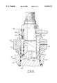
- FIG. 3is a fragmentary view, partially in center axial cross section and partially in elevation, of a '654 type machine modified in accordance with the invention to produce the first embodiment container, and showing the finish portion of the container being extrusion injection molded in accordance with the method of the invention;
- FIG. 4is a fragmentary sectional view similar to that of FIG. 3 but with the extrusion tooling removed from the injection molding tooling and replaced by blow mold halves, FIG. 4 showing a portion of the closed blow-mold with the body portion of the container blown therein;
- FIG. 5is a fragmentary cross-sectional view of the finish portion of a second embodiment of a one-piece self-draining container also constructed in accordance with the invention.
- FIG. 6is a fragmentary cross-sectional view similar to that of FIG. 3 and illustrating a further modification to the tooling of a '654 type machine in accordance with the invention to produce the second embodiment DBS container of FIG. 5.
- FIGS. 1 and 2illustrate a first embodiment of a self-draining container 10 constructed in accordance with the present invention. While the self-draining container 10 as depicted is a plastic bottle specifically designed for liquids, other self-draining containers which fall within the scope of the present invention may be constructed of other materials and used to contain liquids, powders or granules.
- the self-draining container 10includes a body portion 11 of the "broad-shouldered”type which terminates in an opening 12 through which the contents of container 10 can be dispensed.
- a dispensing spout 18is located within and is encircled by wall 16 and includes an upper end pouring lip 20 that extends above a top end edge 22 of wall 16.
- the inner surface of wall 16has formed therein a thread 32 which, in accordance with the aforementioned '659 patent, extends at least two complete turns so that any section cut axially through such wall 16 will have two separate and distinct portions of the thread 32.
- a thread 32which, in accordance with the aforementioned '659 patent, extends at least two complete turns so that any section cut axially through such wall 16 will have two separate and distinct portions of the thread 32.
- forming a container having a spout 18 and an encircling wall 16 with an internal thread 32 of such lengthpermits container 10 to be stripped from the injection mold without causing distortion to thread 32.
- a closure or cap 40includes a top 42 and a depending sidewall 44.
- a sealing ring 46extends radially outwardly from sidewall 44 and a cylindrical skirt 48 depends downwardly below ring 46.
- External threads 49are formed on an exterior surface of skirt 48 and cooperate with threads 32 of the container finish 14 for threadably engaging and removing cap 40 relative to container 10.
- the finish threads 32may be provided on the exterior of wall 18 to mate with cap threads located on the interior of the cap skirt.
- the self-draining container 10may be produced in one-piece within the normal cycle of a blow molding machine of a type known as the aforementioend '654 machine, as modified in accordance with the invention.
- This type of blow moldingmay be characterized as injection/extrusion blow molding and is used by the assignee of the present invention and others with a machine herein designated as the '654 machine. No post-molding container reconfiguring operations are needed to produce the self-draining finish configuration on this type of machine.
- An injection/extrusion tooling portion of a '654 machineis generally indicated by the reference numeral 50 in FIGS. 3 and 4.
- the upper neck or finish portion of the containeris first injection molded in the injection mold tooling of the machine.
- the injection mold toolingis raised away from the orifice of the injection/extrusion die head tooling while a length of heated and plasticized tubing is extruded from the die head.
- the tubingis integrally connected to the injection molded finish and is therefore drawn upwardly as the tubing is extruded.
- blow mold halves of the '654 machineclose around the tubing and air is introduced through the injection mold tooling assembly to expand the tubing in the closed blow mold to form the remainder (i.e., body) of the container.
- the injection stepis shown in FIG. 3 wherein the extrusion die head tooling is generally designated by the numeral 50 and includes a bushing 52 and a mandrel 54 which cooperate to define an annular extrusion orifice 56 through which the heated and plasticized material is expelled upwardly into the injection mold cavity defined by the finish and neck rink assembly injection mold tooling 58 juxtaposed to the extrusion die tooling 50.
- the extrusion die head toolingis generally designated by the numeral 50 and includes a bushing 52 and a mandrel 54 which cooperate to define an annular extrusion orifice 56 through which the heated and plasticized material is expelled upwardly into the injection mold cavity defined by the finish and neck rink assembly injection mold tooling 58 juxtaposed to the extrusion die tooling 50.
- Tooling 58includes a movable neck ring assembly 60 which is mounted (by means not shown) for movement downwardly into engagement with the bushings 52 of the extrusion tooling 50 and in registry with the extrusion orifice 56 during the injection molding step, and for movement upwardly during the extrusion step to thereby draw the oncoming tubing upwardly away from the orifice 56 as it is extruded therefrom.
- the neck ring assembly 60includes neck ring halves 62 and 64 which can open and close radially and which have interior wall portions 66 and 68, respectively, against which the exterior surface of the annular wall 16 of the container finish is molded.
- Core pin 70has an enlarged diameter head portion 80 at its lower end that is contoured on its exterior surface to provide the mold cavity surface for forming the interior surface of container spout 18.
- Core pin 70has a reduced diameter shank portion 82 that extends from head 80 up to a radially protruding collar portion 84.
- a finish insert sleeve subassembly 86made up of a collar part 88 and a sleeve 90 removably fastened to the underside thereof by machine bolts 92, encircles shank 82 of core pin 70 and defines a recessed area 92 extending from the upper edge 94 of core pin head 80 to the undersurface ledge 96 of collar 88 of the finish insert subassembly 86.
- Sleeve 90has a mold-cavity-defining interior surface recess 100 of a configuration to cooperate with exterior surface configuration of core pin 80 to thereby mold form the upper end 20 and the outer surface of spout 18.
- the lower exterior portion of sleeve 90 moldforms the interior surface of wall 16 and has a thread recess 102 in which the thread 32 is molded.
- the length of the thread recess 102is such as to provide at least two complete turns (i.e., 720°) so that in any axial section of the wall 16, there will always be at least two thread segments, regardless of where the axial section is taken throughout the entire 360° circumferential extent of wall 16.
- the mandrel recessed end surface 108is surrounded by an annular frustoconical mandrel surface 112 that is configured to define the injection mold cavity surface that mold forms both the undersurface 114 of web 24 (FIG. 5) and the integral bottom edge 26 of spout 18. This occurs upon mold closure when extrusion die head 50 is oriented to complete the injection mold cavity in cooperation with sleeve 90 and the exterior mold cavity surface of core pin head 80, and with head 80 in abutment with its head face 110 seating tightly on mandrel surface 108.
- FIG. 5illustrates a second embodiment one-piece self-draining container 10' of the invention in which those elements identical to those of container 10 are given like reference numerals, and those elements alike in function are given like reference numerals raised by a prime suffix, and their description not repeated.
- the second embodiment container 10'differs only with respect to the configuration of the apron web wall 24'.
- Web wall 24'is tapered downwardly at a slant so that its lowest region is centered on the spout opening at the gap edges 30' diametrically opposite the pouring lip 20 of spout 18'.
- FIG. 6shows a second embodiment of '654 machine extrusion tooling and neck ring injection tooling as modified in accordance with the invention in order to produce the container 10' of FIG. 5.
- FIG. 5shows that those elements identical to those previously described are given like reference numerals and their description not repeated, and those elements alike in function but modified are given like reference numerals raised by a prime suffix.
- the only changes needed to accomplish the revised embodiment of FIG. 5is to modify the upper end face configuration of mandrel 54' and likewise the corresponding lower surface of finish insert sleeve 104'.
- the lower end head 80' of mold core 70'will fit into a recess in the top surface of mandrel tip 54'.
- the lower finish insert sleeve surface 104' and the top mandrel tip surface 112'have mating slopes to maintain a substantially uniform gap to allow for a consistent material thickness on web 24'.
- the opposing faces 108, 110' of mandrel 54' and head 80'are horizontal rather than angulated, which eliminates any side loading problems that might otherwise occur in the tooling.
- the pour spout 18, 18'is integrally joined to the container, i.e., made in one piece with the container as molded, and is integrally joined to the surrounding container neck by a drip collecting apron web or ledge that is tapered or angulated downwardly at a steep angle throughout its circumference, thereby providing an improved drain gutter contour better promoting product drippage flow toward the reduced diameter pour spout to encourage gravity-induced flow of liquid back into the container.
- this improved container drain gutter configurationis obtained by utilizing the already existing '654 type blow molding machines with only minor modifications thereto. As illustrated in FIGS. 3 and 6, only the upper face of mandrel 54 need be machined and ground to the recessed configuration of either FIG. 3 or FIG. 6. Likewise the head 80 or 80' of the core pin assembly 70 or 70' needs to be replaced with an axially elongated head, the finish insert sleeve 90 or 90' modified by extending the sleeve axially, and contouring the sleeve bottom surface 104 or 104' to correspond with the contour of mandrel tip surface 112 or 112'. All the remaining components of the machine remain unchanged, and the cycle of operation of the machine is not affected Despite the improved configuration of the web wall 24 or 24', the cross sectional thickness of the web wall remains uniform and relatively thin so as to not affect machine cycle time.
Landscapes
- Engineering & Computer Science (AREA)
- Mechanical Engineering (AREA)
- Manufacturing & Machinery (AREA)
- Blow-Moulding Or Thermoforming Of Plastics Or The Like (AREA)
- Moulds For Moulding Plastics Or The Like (AREA)
- Containers Having Bodies Formed In One Piece (AREA)
- Details Of Rigid Or Semi-Rigid Containers (AREA)
- Closures For Containers (AREA)
- Making Paper Articles (AREA)
- Processing And Handling Of Plastics And Other Materials For Molding In General (AREA)
Abstract
Description
Claims (8)
Priority Applications (11)
| Application Number | Priority Date | Filing Date | Title |
|---|---|---|---|
| US09/114,481US6123231A (en) | 1998-07-13 | 1998-07-13 | Plastic container with drain back spout and method and apparatus for making same |
| DE1999627753DE69927753T2 (en) | 1998-07-13 | 1999-07-05 | Plastic container with Rückflussaussgiesser, method and apparatus for its preparation |
| NZ33658899ANZ336588A (en) | 1998-07-13 | 1999-07-05 | Plastic container with drain back spout integrally moulded using injection-extrusion blow moulding |
| EP19990305313EP0972714B1 (en) | 1998-07-13 | 1999-07-05 | Plastic container with drain back spout and method and apparatus for making same |
| AT99305313TATE307063T1 (en) | 1998-07-13 | 1999-07-05 | PLASTIC CONTAINER WITH BACKFLOW SPOUT, METHOD AND DEVICE FOR PRODUCING IT |
| CA 2277258CA2277258C (en) | 1998-07-13 | 1999-07-09 | Plastic container with drain back spout and method and apparatus for making same |
| AU39174/99AAU750546B2 (en) | 1998-07-13 | 1999-07-12 | Plastic container with drain back spout and method and apparatus for making same |
| ZA9904495AZA994495B (en) | 1998-07-13 | 1999-07-12 | Plastic container with drain back spout and method and apparatus for making same. |
| BR9902734ABR9902734A (en) | 1998-07-13 | 1999-07-13 | Plastic container with return drain nozzle and method and apparatus for carrying out the same |
| JP19851999AJP2000079960A (en) | 1998-07-13 | 1999-07-13 | Plastic container with excess liquid return type spout and manufacturing method and apparatus therefor |
| US09/574,855US6500380B1 (en) | 1998-07-13 | 2000-05-19 | Method and apparatus for making a plastic container with drain back spout |
Applications Claiming Priority (1)
| Application Number | Priority Date | Filing Date | Title |
|---|---|---|---|
| US09/114,481US6123231A (en) | 1998-07-13 | 1998-07-13 | Plastic container with drain back spout and method and apparatus for making same |
Related Child Applications (1)
| Application Number | Title | Priority Date | Filing Date |
|---|---|---|---|
| US09/574,855DivisionUS6500380B1 (en) | 1998-07-13 | 2000-05-19 | Method and apparatus for making a plastic container with drain back spout |
Publications (1)
| Publication Number | Publication Date |
|---|---|
| US6123231Atrue US6123231A (en) | 2000-09-26 |
Family
ID=22355490
Family Applications (2)
| Application Number | Title | Priority Date | Filing Date |
|---|---|---|---|
| US09/114,481Expired - LifetimeUS6123231A (en) | 1998-07-13 | 1998-07-13 | Plastic container with drain back spout and method and apparatus for making same |
| US09/574,855Expired - Fee RelatedUS6500380B1 (en) | 1998-07-13 | 2000-05-19 | Method and apparatus for making a plastic container with drain back spout |
Family Applications After (1)
| Application Number | Title | Priority Date | Filing Date |
|---|---|---|---|
| US09/574,855Expired - Fee RelatedUS6500380B1 (en) | 1998-07-13 | 2000-05-19 | Method and apparatus for making a plastic container with drain back spout |
Country Status (10)
| Country | Link |
|---|---|
| US (2) | US6123231A (en) |
| EP (1) | EP0972714B1 (en) |
| JP (1) | JP2000079960A (en) |
| AT (1) | ATE307063T1 (en) |
| AU (1) | AU750546B2 (en) |
| BR (1) | BR9902734A (en) |
| CA (1) | CA2277258C (en) |
| DE (1) | DE69927753T2 (en) |
| NZ (1) | NZ336588A (en) |
| ZA (1) | ZA994495B (en) |
Cited By (27)
| Publication number | Priority date | Publication date | Assignee | Title |
|---|---|---|---|---|
| US6530500B2 (en) | 1999-07-08 | 2003-03-11 | The Sherwin-Williams Company | Storage and dispensing container for viscous fluids, paints and the like, and method of minimizing dripping |
| USD472145S1 (en) | 2001-08-14 | 2003-03-25 | Nottingham-Spirk Partners, Llc | Paint container lid |
| USD473790S1 (en) | 2001-08-14 | 2003-04-29 | Nottingham-Spirk Partners, Llc | Paint container insert |
| USD480973S1 (en) | 2001-08-14 | 2003-10-21 | Nsi Innovation Llp | Design for a round paint container |
| USD482973S1 (en) | 2001-08-14 | 2003-12-02 | Nsi Innovation Llc | Square paint container |
| US20050087548A1 (en)* | 2003-10-24 | 2005-04-28 | Erie County Plastics Corporation | Drain-back snap-on pour spout fitment closure |
| US6896156B2 (en) | 2002-07-03 | 2005-05-24 | The Sherwin-Williams Company | Plastic paint container having a cube-shaped body |
| USD510866S1 (en) | 2001-08-14 | 2005-10-25 | The Sherwin-Williams Company | Round paint container |
| USD511101S1 (en) | 2001-08-14 | 2005-11-01 | The Sherwin-Williams Company | Round paint container with handle |
| US6983862B2 (en) | 2001-04-18 | 2006-01-10 | The Sherwin-Williams Company | Container and lid assembly |
| US7014078B2 (en) | 2001-12-05 | 2006-03-21 | Masterchem Industries Llc | Container |
| US20060073233A1 (en)* | 2003-05-15 | 2006-04-06 | Struble Douglas S | Method and apparatus for blow molding hollow plastic containers |
| USD518731S1 (en) | 2005-01-05 | 2006-04-11 | The Clorox Company | Bottle |
| US7032756B2 (en) | 2000-04-11 | 2006-04-25 | Wylie Arun M | Container |
| US20060097006A1 (en)* | 2005-10-11 | 2006-05-11 | Erie County Plastics Corporation | Pour spout fitment with internal cut off |
| US20060131330A1 (en)* | 2004-12-21 | 2006-06-22 | Erie County Plastics Corporation | Drain-back spout fitment closure with drip-less pour tip |
| US20060163252A1 (en)* | 2005-01-24 | 2006-07-27 | Letica Corporation | Container |
| USD563228S1 (en) | 2001-08-14 | 2008-03-04 | The Sherwin-Williams Company | Container for coating materials |
| US20090045224A1 (en)* | 2007-08-17 | 2009-02-19 | Joel Faaborg | Liquid product pouring and measuring package with drain-back spout fitment and tight-sealing measuring cup assembly |
| USD589348S1 (en)* | 2006-12-05 | 2009-03-31 | The Dial Corporation | Dosing spout/cap |
| CN100497103C (en)* | 2003-07-25 | 2009-06-10 | 马斯特切姆工业有限责任公司 | Insert for a container, container and paint container |
| US20090314738A1 (en)* | 2008-06-23 | 2009-12-24 | Siacunco James P | Bottle cap with internal brush |
| US20100213211A1 (en)* | 2009-02-26 | 2010-08-26 | Whaling Audrey M | Bottle Cap With Dosing and Pretreatment |
| US20110089195A1 (en)* | 2007-05-17 | 2011-04-21 | Amcor Limited | Molded preform and container having integrated pour spout |
| US8663419B2 (en) | 2010-11-30 | 2014-03-04 | Ecologic | Manual container assembly and liner integration fixture for pulp-molded shell with polymer liner container systems |
| US9446885B2 (en) | 2012-11-10 | 2016-09-20 | Kraft Foods Group Brands Llc | Container with a removable measuring cap |
| US20220250782A1 (en)* | 2016-12-12 | 2022-08-11 | OnMyWhey, LLC | Portable Container And Method Of Use |
Families Citing this family (12)
| Publication number | Priority date | Publication date | Assignee | Title |
|---|---|---|---|---|
| US6648188B2 (en)* | 1999-12-21 | 2003-11-18 | Owens-Brockway Plastic Products Inc. | Liquid dispensing package and method of manufacture |
| KR100387563B1 (en)* | 2001-03-14 | 2003-06-18 | 주식회사 엘지생활건강 | manufacturing method for integral structure bottle |
| US8430259B2 (en)* | 2008-04-04 | 2013-04-30 | Stokely-Van Camp, Inc. | Closure with flexible diaphragm |
| US7980403B2 (en)* | 2008-04-04 | 2011-07-19 | Stokely-Van Camp, Inc. | Container closure with internal threading system |
| FR2934519B1 (en)* | 2008-08-01 | 2013-06-28 | Oreal | PROCESS FOR MANUFACTURING A FIRST CONTAINER OF COSMETIC PRODUCT, MOLD, COLLAR AND RECIPIENT |
| CA2741051A1 (en)* | 2008-11-06 | 2010-05-14 | The Procter & Gamble Company | Container and preform with an integrated spout |
| DE102011000902B3 (en)* | 2011-02-23 | 2011-12-22 | Kunststofftechnik Waidhofen An Der Thaya Gmbh | Closure for liquid/powdered laundry detergent bottle, has cap provided with halt screw thread, where increase of thread differs from increase of mounting thread such that output connecting piece is pulled out of closure connecting piece |
| FR3046782A1 (en)* | 2016-01-14 | 2017-07-21 | Lisa Colin | ASSEMBLY COMPRISING A CONTAINER HAVING A SEPARATE THREAD OF THE COLLAR RECEIVING A SCREW CAP |
| EP3587061A1 (en)* | 2018-06-27 | 2020-01-01 | Resilux N.V. | Preform and container adapted for accommodating an insert piece, with methods and apparatus for their production |
| EP3695948B1 (en)* | 2019-02-15 | 2021-11-24 | Tetra Laval Holdings & Finance S.A. | A mould, and tools for such mould |
| RU201343U1 (en)* | 2020-10-16 | 2020-12-11 | Публичное акционерное общество «Татнефть» имени В.Д. Шашина | Device for draining water carriers |
| US20240246726A1 (en)* | 2021-07-30 | 2024-07-25 | Yoshino Kogyosho Co., Ltd. | Liquid container and liquid container with content liquid |
Citations (9)
| Publication number | Priority date | Publication date | Assignee | Title |
|---|---|---|---|---|
| US2804654A (en)* | 1954-03-03 | 1957-09-03 | Owens Illinois Glass Co | Method of forming hollow plastic articles |
| US4640855A (en)* | 1985-10-25 | 1987-02-03 | Owens-Illinois, Inc. | Plastic container with integral spout |
| US4917269A (en)* | 1989-05-10 | 1990-04-17 | Owens-Illinois Closure Inc. | Liquid containing and dispensing package |
| US4989757A (en)* | 1988-02-25 | 1991-02-05 | Owens-Illinois Plastic Products Inc. | Plastic container with self-draining feature |
| US5020692A (en)* | 1986-05-15 | 1991-06-04 | Plastipak Packaging, Inc. | Container including unitary blow molded bottle having drain-back dispensing spout and plastic insert |
| US5114659A (en)* | 1988-02-25 | 1992-05-19 | Owens-Illinois Plastic Products Inc. | Blow molding method for forming a one-piece self-draining container |
| US5207356A (en)* | 1988-02-25 | 1993-05-04 | Owens-Illinois Plastic Products Inc. | Self-draining container |
| US5462202A (en)* | 1994-08-25 | 1995-10-31 | Owens-Illinois Closure Inc. | Liquid containing and dispensing package |
| US5566862A (en)* | 1994-10-24 | 1996-10-22 | Owens-Illinois Closure Inc. | Liquid containing and dispensing package |
Family Cites Families (8)
| Publication number | Priority date | Publication date | Assignee | Title |
|---|---|---|---|---|
| US4929410A (en)* | 1984-12-06 | 1990-05-29 | The Procter & Gamble Company | Method for blow-molding a container having a neck-portion with internal attachment means |
| US4917268A (en)* | 1988-06-20 | 1990-04-17 | The Clorox Company | Liquid dispensing package with drainback spout |
| CH676572A5 (en)* | 1988-12-07 | 1991-02-15 | Claropac Ag | |
| US4941815A (en)* | 1989-01-19 | 1990-07-17 | Sunbeam Plastics Corporation | Injection-blow molding apparatus |
| US5234130A (en)* | 1991-03-22 | 1993-08-10 | Manhattan Products, Inc. | Dispensing package for a pourable material having a bottle, a pour-back spout and a closure |
| ES2079833T3 (en)* | 1991-09-12 | 1996-01-16 | Soplar Sa | CONTAINER MOLDED BY BLOWING, FOR EXAMPLE, PLASTIC BOTTLE, AND CLOSING LID FOR THE CONTAINER. |
| US5435467A (en)* | 1994-04-20 | 1995-07-25 | Phoenix Closures, Inc. | Stackable dispenser closure |
| US5855299A (en)* | 1997-04-04 | 1999-01-05 | Graham Packaging Corporation | Plastic container dispensing fitment |
- 1998
- 1998-07-13USUS09/114,481patent/US6123231A/ennot_activeExpired - Lifetime
- 1999
- 1999-07-05ATAT99305313Tpatent/ATE307063T1/ennot_activeIP Right Cessation
- 1999-07-05DEDE1999627753patent/DE69927753T2/ennot_activeExpired - Fee Related
- 1999-07-05EPEP19990305313patent/EP0972714B1/ennot_activeExpired - Lifetime
- 1999-07-05NZNZ33658899Apatent/NZ336588A/enunknown
- 1999-07-09CACA 2277258patent/CA2277258C/ennot_activeExpired - Fee Related
- 1999-07-12AUAU39174/99Apatent/AU750546B2/ennot_activeCeased
- 1999-07-12ZAZA9904495Apatent/ZA994495B/enunknown
- 1999-07-13BRBR9902734Apatent/BR9902734A/ennot_activeApplication Discontinuation
- 1999-07-13JPJP19851999Apatent/JP2000079960A/enactivePending
- 2000
- 2000-05-19USUS09/574,855patent/US6500380B1/ennot_activeExpired - Fee Related
Patent Citations (9)
| Publication number | Priority date | Publication date | Assignee | Title |
|---|---|---|---|---|
| US2804654A (en)* | 1954-03-03 | 1957-09-03 | Owens Illinois Glass Co | Method of forming hollow plastic articles |
| US4640855A (en)* | 1985-10-25 | 1987-02-03 | Owens-Illinois, Inc. | Plastic container with integral spout |
| US5020692A (en)* | 1986-05-15 | 1991-06-04 | Plastipak Packaging, Inc. | Container including unitary blow molded bottle having drain-back dispensing spout and plastic insert |
| US4989757A (en)* | 1988-02-25 | 1991-02-05 | Owens-Illinois Plastic Products Inc. | Plastic container with self-draining feature |
| US5114659A (en)* | 1988-02-25 | 1992-05-19 | Owens-Illinois Plastic Products Inc. | Blow molding method for forming a one-piece self-draining container |
| US5207356A (en)* | 1988-02-25 | 1993-05-04 | Owens-Illinois Plastic Products Inc. | Self-draining container |
| US4917269A (en)* | 1989-05-10 | 1990-04-17 | Owens-Illinois Closure Inc. | Liquid containing and dispensing package |
| US5462202A (en)* | 1994-08-25 | 1995-10-31 | Owens-Illinois Closure Inc. | Liquid containing and dispensing package |
| US5566862A (en)* | 1994-10-24 | 1996-10-22 | Owens-Illinois Closure Inc. | Liquid containing and dispensing package |
Cited By (41)
| Publication number | Priority date | Publication date | Assignee | Title |
|---|---|---|---|---|
| US7703641B2 (en) | 1999-07-08 | 2010-04-27 | The Sherwin-Williams Company | Storage and dispensing container for paint |
| US7325687B2 (en) | 1999-07-08 | 2008-02-05 | The Sherwin-Williams Company | Storage and dispensing container for paint |
| US6530500B2 (en) | 1999-07-08 | 2003-03-11 | The Sherwin-Williams Company | Storage and dispensing container for viscous fluids, paints and the like, and method of minimizing dripping |
| US6634525B2 (en) | 1999-07-08 | 2003-10-21 | The Sherwin-Williams Company | Storage and dispensing container for paint |
| US7032756B2 (en) | 2000-04-11 | 2006-04-25 | Wylie Arun M | Container |
| US6983862B2 (en) | 2001-04-18 | 2006-01-10 | The Sherwin-Williams Company | Container and lid assembly |
| USD473790S1 (en) | 2001-08-14 | 2003-04-29 | Nottingham-Spirk Partners, Llc | Paint container insert |
| USD480973S1 (en) | 2001-08-14 | 2003-10-21 | Nsi Innovation Llp | Design for a round paint container |
| USD472145S1 (en) | 2001-08-14 | 2003-03-25 | Nottingham-Spirk Partners, Llc | Paint container lid |
| USD573475S1 (en) | 2001-08-14 | 2008-07-22 | The Sherwin-Williams Company | Square paint container |
| USD510866S1 (en) | 2001-08-14 | 2005-10-25 | The Sherwin-Williams Company | Round paint container |
| USD511101S1 (en) | 2001-08-14 | 2005-11-01 | The Sherwin-Williams Company | Round paint container with handle |
| USD563228S1 (en) | 2001-08-14 | 2008-03-04 | The Sherwin-Williams Company | Container for coating materials |
| USD500953S1 (en) | 2001-08-14 | 2005-01-18 | The Sherwin-Williams Company | Container for coating materials |
| USD482973S1 (en) | 2001-08-14 | 2003-12-02 | Nsi Innovation Llc | Square paint container |
| US7036693B2 (en) | 2001-12-05 | 2006-05-02 | Masterchem Industries Llc | Paint container |
| US7014078B2 (en) | 2001-12-05 | 2006-03-21 | Masterchem Industries Llc | Container |
| US7156265B2 (en) | 2001-12-05 | 2007-01-02 | Masterchem Industries Llc | Container |
| US6896156B2 (en) | 2002-07-03 | 2005-05-24 | The Sherwin-Williams Company | Plastic paint container having a cube-shaped body |
| US20060073233A1 (en)* | 2003-05-15 | 2006-04-06 | Struble Douglas S | Method and apparatus for blow molding hollow plastic containers |
| US7153127B2 (en) | 2003-05-15 | 2006-12-26 | Graham Packaging Plastic Products Inc. | Method and apparatus for blow molding hollow plastic containers |
| CN100497103C (en)* | 2003-07-25 | 2009-06-10 | 马斯特切姆工业有限责任公司 | Insert for a container, container and paint container |
| US20050087548A1 (en)* | 2003-10-24 | 2005-04-28 | Erie County Plastics Corporation | Drain-back snap-on pour spout fitment closure |
| US6923341B2 (en) | 2003-10-24 | 2005-08-02 | Erie County Plastics Corporation | Drain-back snap-on pour spout fitment closure |
| US7686188B2 (en) | 2004-12-21 | 2010-03-30 | Berry Plastics Corporation | Drain-back spout fitment closure with drip-less pour tip |
| US20060131330A1 (en)* | 2004-12-21 | 2006-06-22 | Erie County Plastics Corporation | Drain-back spout fitment closure with drip-less pour tip |
| USD518731S1 (en) | 2005-01-05 | 2006-04-11 | The Clorox Company | Bottle |
| US20060163252A1 (en)* | 2005-01-24 | 2006-07-27 | Letica Corporation | Container |
| US20060097006A1 (en)* | 2005-10-11 | 2006-05-11 | Erie County Plastics Corporation | Pour spout fitment with internal cut off |
| USD589348S1 (en)* | 2006-12-05 | 2009-03-31 | The Dial Corporation | Dosing spout/cap |
| US8955716B2 (en)* | 2007-05-17 | 2015-02-17 | Amcor Limited | Molded preform and container having integrated pour spout |
| US20110089195A1 (en)* | 2007-05-17 | 2011-04-21 | Amcor Limited | Molded preform and container having integrated pour spout |
| US7959034B2 (en) | 2007-08-17 | 2011-06-14 | The Dial Corporation | Liquid product pouring and measuring package with drain-back spout fitment and tight-sealing measuring cup assembly |
| US20090045224A1 (en)* | 2007-08-17 | 2009-02-19 | Joel Faaborg | Liquid product pouring and measuring package with drain-back spout fitment and tight-sealing measuring cup assembly |
| US20090314738A1 (en)* | 2008-06-23 | 2009-12-24 | Siacunco James P | Bottle cap with internal brush |
| US20100213211A1 (en)* | 2009-02-26 | 2010-08-26 | Whaling Audrey M | Bottle Cap With Dosing and Pretreatment |
| WO2012061174A3 (en)* | 2010-11-05 | 2012-08-16 | Amcor Limited | Molded preform and container having integrated pour spout |
| US8663419B2 (en) | 2010-11-30 | 2014-03-04 | Ecologic | Manual container assembly and liner integration fixture for pulp-molded shell with polymer liner container systems |
| US9126719B2 (en) | 2010-11-30 | 2015-09-08 | Ecologic | Manual container assembly and liner integration fixture for pulp-molded shell with polymer liner container systems |
| US9446885B2 (en) | 2012-11-10 | 2016-09-20 | Kraft Foods Group Brands Llc | Container with a removable measuring cap |
| US20220250782A1 (en)* | 2016-12-12 | 2022-08-11 | OnMyWhey, LLC | Portable Container And Method Of Use |
Also Published As
| Publication number | Publication date |
|---|---|
| AU750546B2 (en) | 2002-07-18 |
| DE69927753T2 (en) | 2006-06-29 |
| ZA994495B (en) | 2000-01-27 |
| CA2277258C (en) | 2006-10-03 |
| BR9902734A (en) | 2000-03-21 |
| CA2277258A1 (en) | 2000-01-13 |
| ATE307063T1 (en) | 2005-11-15 |
| EP0972714B1 (en) | 2005-10-19 |
| JP2000079960A (en) | 2000-03-21 |
| NZ336588A (en) | 2001-01-26 |
| DE69927753D1 (en) | 2006-03-02 |
| EP0972714A2 (en) | 2000-01-19 |
| EP0972714A3 (en) | 2002-04-17 |
| US6500380B1 (en) | 2002-12-31 |
| AU3917499A (en) | 2000-02-10 |
Similar Documents
| Publication | Publication Date | Title |
|---|---|---|
| US6123231A (en) | Plastic container with drain back spout and method and apparatus for making same | |
| US5429789A (en) | Plastic container with self-draining feature | |
| US5207356A (en) | Self-draining container | |
| US5114659A (en) | Blow molding method for forming a one-piece self-draining container | |
| US4929410A (en) | Method for blow-molding a container having a neck-portion with internal attachment means | |
| US4578028A (en) | Expandable core pin for blow-molding a container having a neck-portion with internal attachment means | |
| EP0329883B1 (en) | Plastic container with self-draining feature | |
| US6685041B1 (en) | Dual-chamber container and closure package | |
| US4806091A (en) | Apparatus for manufacturing a plastic hollow body with a blow-molded body part | |
| US4753591A (en) | Apparatus for forming the neck finish of blow molded containers | |
| US20180281254A1 (en) | Cap Manufacture Methods and Apparatus | |
| US6602459B1 (en) | Dual-chamber container, and method and apparatus for its manufacture | |
| JP3217361B2 (en) | Accumulator head for extrusion blow molding machine | |
| CA1319910C (en) | Self-draining container | |
| US20080241441A1 (en) | Overmolding of a tube head on a skirt end to give a tube with a high restitution rate | |
| HK1000592B (en) | Self-draining container | |
| US6077471A (en) | Mold for forming a container having a continuous neck finish and method for using same | |
| MXPA99006450A (en) | Plastic container with rear screw nozzle and method and apparatus to manufacture the mi | |
| RU2230662C1 (en) | Mould and method for casting of plastic cartridge case | |
| HK1000590B (en) | Plastic container with self-draining feature | |
| NZ235769A (en) | Method for moulding a plastics, self-draining container | |
| CA1296496C (en) | Apparatus for manufacturing a plastic hollow body, which has a slidable mandrel | |
| JP2007520367A (en) | Molding method and apparatus | |
| CN1241522A (en) | Plastic container with drain back spout and method and apparatus for making same |
Legal Events
| Date | Code | Title | Description |
|---|---|---|---|
| AS | Assignment | Owner name:OWENS-BROCKWAY PLASTIC PRODUCTS INC., OHIO Free format text:ASSIGNMENT OF ASSIGNORS INTEREST;ASSIGNOR:GEISINGER, GREGORY A.;REEL/FRAME:009315/0340 Effective date:19980708 | |
| STCF | Information on status: patent grant | Free format text:PATENTED CASE | |
| FPAY | Fee payment | Year of fee payment:4 | |
| AS | Assignment | Owner name:GRAHAM PACKAGING PLASTIC PRODUCTS INC., PENNSYLVAN Free format text:CHANGE OF NAME;ASSIGNOR:OWENS-BROCKWAY PLASTIC PRODUCTS INC.;REEL/FRAME:017946/0345 Effective date:20041021 | |
| AS | Assignment | Owner name:DEUTSCHE BANK AG CAYMAN ISLANDS BRANCH AS SECOND-L Free format text:GRANT OF SECURITY INTEREST;ASSIGNOR:GRAHAM PACKAGING COMPANY, L.P.;REEL/FRAME:015552/0299 Effective date:20041007 Owner name:DEUTSCHE BANK AG CAYMAN ISLANDS BRANCH, NEW JERSEY Free format text:GRANT OF SECURITY INTEREST;ASSIGNOR:GRAHAM PACKAGING COMPANY, L.P.;REEL/FRAME:015980/0213 Effective date:20041007 | |
| AS | Assignment | Owner name:GRAHAM PACKAGING COMPANY, L.P., PENNSYLVANIA Free format text:PATENT RELEASE;ASSIGNOR:DEUTSCHE BANK AG, CAYMAN ISLANDS BRANCH, AS COLLATERAL AGENT;REEL/FRAME:019140/0509 Effective date:20070330 | |
| FPAY | Fee payment | Year of fee payment:8 | |
| REMI | Maintenance fee reminder mailed | ||
| AS | Assignment | Owner name:GRAHAM PACKAGING COMPANY, L.P., PENNSYLVANIA Free format text:RELEASE OF SECURITY INTERESTS;ASSIGNOR:DEUTSCHE BANK AG, GAYMAN ISLANDS BRANCH, AS COLLATERAL AGENT;REEL/FRAME:027011/0572 Effective date:20110908 | |
| AS | Assignment | Owner name:REYNOLDS GROUP HOLDINGS INC., NEW ZEALAND Free format text:SECURITY AGREEMENT;ASSIGNOR:GRAHAM PACKAGING PLASTIC PRODUCTS INC.;REEL/FRAME:026970/0750 Effective date:20110908 | |
| AS | Assignment | Owner name:GRAHAM PACKAGING PLASTIC PRODUCTS INC., PENNSYLVAN Free format text:TERMINATION AND RELEASE OF SECURITY INTEREST IN PATENTS;ASSIGNOR:REYNOLDS GROUP HOLDINGS INC.;REEL/FRAME:027910/0549 Effective date:20120320 Owner name:THE BANK OF NEW YORK MELLON, NEW YORK Free format text:PATENT SECURITY AGREEMENT;ASSIGNOR:GRAHAM PACKAGING PLASTIC PRODUCTS INC.;REEL/FRAME:027910/0639 Effective date:20120320 | |
| FPAY | Fee payment | Year of fee payment:12 | |
| AS | Assignment | Owner name:GRAHAM PACKAGING PLASTIC PRODUCTS INC., PENNSYLVANIA Free format text:RELEASE OF SECURITY INTEREST IN CERTAIN PATENT COLLATERAL;ASSIGNOR:THE BANK OF NEW YORK MELLON, AS THE COLLATERAL AGENT AND TRUSTEE;REEL/FRAME:053396/0696 Effective date:20200804 | |
| AS | Assignment | Owner name:GRAHAM PACKAGING COMPANY, L.P., PENNSYLVANIA Free format text:RELEASE OF SECURITY INTEREST IN CERTAIN PATENT COLLATERAL;ASSIGNOR:DEUTSCHE BANK AG CAYMAN ISLANDS BRANCH, AS COLLATERAL AGENT AND GRANTEE;REEL/FRAME:053414/0001 Effective date:20200805 |