US6122564A - Apparatus and methods for monitoring and controlling multi-layer laser cladding - Google Patents
Apparatus and methods for monitoring and controlling multi-layer laser claddingDownload PDFInfo
- Publication number
- US6122564A US6122564AUS09/107,912US10791298AUS6122564AUS 6122564 AUS6122564 AUS 6122564AUS 10791298 AUS10791298 AUS 10791298AUS 6122564 AUS6122564 AUS 6122564A
- Authority
- US
- United States
- Prior art keywords
- laser
- substrate
- deposit
- height
- article
- Prior art date
- Legal status (The legal status is an assumption and is not a legal conclusion. Google has not performed a legal analysis and makes no representation as to the accuracy of the status listed.)
- Expired - Lifetime
Links
Images


Classifications
- B—PERFORMING OPERATIONS; TRANSPORTING
- B23—MACHINE TOOLS; METAL-WORKING NOT OTHERWISE PROVIDED FOR
- B23K—SOLDERING OR UNSOLDERING; WELDING; CLADDING OR PLATING BY SOLDERING OR WELDING; CUTTING BY APPLYING HEAT LOCALLY, e.g. FLAME CUTTING; WORKING BY LASER BEAM
- B23K26/00—Working by laser beam, e.g. welding, cutting or boring
- B23K26/02—Positioning or observing the workpiece, e.g. with respect to the point of impact; Aligning, aiming or focusing the laser beam
- B23K26/03—Observing, e.g. monitoring, the workpiece
- B23K26/032—Observing, e.g. monitoring, the workpiece using optical means
- G—PHYSICS
- G06—COMPUTING OR CALCULATING; COUNTING
- G06Q—INFORMATION AND COMMUNICATION TECHNOLOGY [ICT] SPECIALLY ADAPTED FOR ADMINISTRATIVE, COMMERCIAL, FINANCIAL, MANAGERIAL OR SUPERVISORY PURPOSES; SYSTEMS OR METHODS SPECIALLY ADAPTED FOR ADMINISTRATIVE, COMMERCIAL, FINANCIAL, MANAGERIAL OR SUPERVISORY PURPOSES, NOT OTHERWISE PROVIDED FOR
- G06Q50/00—Information and communication technology [ICT] specially adapted for implementation of business processes of specific business sectors, e.g. utilities or tourism
- G06Q50/04—Manufacturing
- B—PERFORMING OPERATIONS; TRANSPORTING
- B22—CASTING; POWDER METALLURGY
- B22F—WORKING METALLIC POWDER; MANUFACTURE OF ARTICLES FROM METALLIC POWDER; MAKING METALLIC POWDER; APPARATUS OR DEVICES SPECIALLY ADAPTED FOR METALLIC POWDER
- B22F10/00—Additive manufacturing of workpieces or articles from metallic powder
- B22F10/20—Direct sintering or melting
- B22F10/25—Direct deposition of metal particles, e.g. direct metal deposition [DMD] or laser engineered net shaping [LENS]
- B—PERFORMING OPERATIONS; TRANSPORTING
- B22—CASTING; POWDER METALLURGY
- B22F—WORKING METALLIC POWDER; MANUFACTURE OF ARTICLES FROM METALLIC POWDER; MAKING METALLIC POWDER; APPARATUS OR DEVICES SPECIALLY ADAPTED FOR METALLIC POWDER
- B22F10/00—Additive manufacturing of workpieces or articles from metallic powder
- B22F10/30—Process control
- B22F10/36—Process control of energy beam parameters
- B—PERFORMING OPERATIONS; TRANSPORTING
- B22—CASTING; POWDER METALLURGY
- B22F—WORKING METALLIC POWDER; MANUFACTURE OF ARTICLES FROM METALLIC POWDER; MAKING METALLIC POWDER; APPARATUS OR DEVICES SPECIALLY ADAPTED FOR METALLIC POWDER
- B22F12/00—Apparatus or devices specially adapted for additive manufacturing; Auxiliary means for additive manufacturing; Combinations of additive manufacturing apparatus or devices with other processing apparatus or devices
- B22F12/30—Platforms or substrates
- B22F12/33—Platforms or substrates translatory in the deposition plane
- B—PERFORMING OPERATIONS; TRANSPORTING
- B22—CASTING; POWDER METALLURGY
- B22F—WORKING METALLIC POWDER; MANUFACTURE OF ARTICLES FROM METALLIC POWDER; MAKING METALLIC POWDER; APPARATUS OR DEVICES SPECIALLY ADAPTED FOR METALLIC POWDER
- B22F12/00—Apparatus or devices specially adapted for additive manufacturing; Auxiliary means for additive manufacturing; Combinations of additive manufacturing apparatus or devices with other processing apparatus or devices
- B22F12/40—Radiation means
- B22F12/44—Radiation means characterised by the configuration of the radiation means
- B—PERFORMING OPERATIONS; TRANSPORTING
- B22—CASTING; POWDER METALLURGY
- B22F—WORKING METALLIC POWDER; MANUFACTURE OF ARTICLES FROM METALLIC POWDER; MAKING METALLIC POWDER; APPARATUS OR DEVICES SPECIALLY ADAPTED FOR METALLIC POWDER
- B22F12/00—Apparatus or devices specially adapted for additive manufacturing; Auxiliary means for additive manufacturing; Combinations of additive manufacturing apparatus or devices with other processing apparatus or devices
- B22F12/50—Means for feeding of material, e.g. heads
- B22F12/53—Nozzles
- B—PERFORMING OPERATIONS; TRANSPORTING
- B22—CASTING; POWDER METALLURGY
- B22F—WORKING METALLIC POWDER; MANUFACTURE OF ARTICLES FROM METALLIC POWDER; MAKING METALLIC POWDER; APPARATUS OR DEVICES SPECIALLY ADAPTED FOR METALLIC POWDER
- B22F12/00—Apparatus or devices specially adapted for additive manufacturing; Auxiliary means for additive manufacturing; Combinations of additive manufacturing apparatus or devices with other processing apparatus or devices
- B22F12/90—Means for process control, e.g. cameras or sensors
- B—PERFORMING OPERATIONS; TRANSPORTING
- B23—MACHINE TOOLS; METAL-WORKING NOT OTHERWISE PROVIDED FOR
- B23K—SOLDERING OR UNSOLDERING; WELDING; CLADDING OR PLATING BY SOLDERING OR WELDING; CUTTING BY APPLYING HEAT LOCALLY, e.g. FLAME CUTTING; WORKING BY LASER BEAM
- B23K26/00—Working by laser beam, e.g. welding, cutting or boring
- B23K26/20—Bonding
- B23K26/32—Bonding taking account of the properties of the material involved
- B—PERFORMING OPERATIONS; TRANSPORTING
- B23—MACHINE TOOLS; METAL-WORKING NOT OTHERWISE PROVIDED FOR
- B23K—SOLDERING OR UNSOLDERING; WELDING; CLADDING OR PLATING BY SOLDERING OR WELDING; CUTTING BY APPLYING HEAT LOCALLY, e.g. FLAME CUTTING; WORKING BY LASER BEAM
- B23K26/00—Working by laser beam, e.g. welding, cutting or boring
- B23K26/34—Laser welding for purposes other than joining
- B—PERFORMING OPERATIONS; TRANSPORTING
- B22—CASTING; POWDER METALLURGY
- B22F—WORKING METALLIC POWDER; MANUFACTURE OF ARTICLES FROM METALLIC POWDER; MAKING METALLIC POWDER; APPARATUS OR DEVICES SPECIALLY ADAPTED FOR METALLIC POWDER
- B22F12/00—Apparatus or devices specially adapted for additive manufacturing; Auxiliary means for additive manufacturing; Combinations of additive manufacturing apparatus or devices with other processing apparatus or devices
- B22F12/22—Driving means
- B22F12/224—Driving means for motion along a direction within the plane of a layer
- B—PERFORMING OPERATIONS; TRANSPORTING
- B22—CASTING; POWDER METALLURGY
- B22F—WORKING METALLIC POWDER; MANUFACTURE OF ARTICLES FROM METALLIC POWDER; MAKING METALLIC POWDER; APPARATUS OR DEVICES SPECIALLY ADAPTED FOR METALLIC POWDER
- B22F12/00—Apparatus or devices specially adapted for additive manufacturing; Auxiliary means for additive manufacturing; Combinations of additive manufacturing apparatus or devices with other processing apparatus or devices
- B22F12/40—Radiation means
- B22F12/41—Radiation means characterised by the type, e.g. laser or electron beam
- B—PERFORMING OPERATIONS; TRANSPORTING
- B22—CASTING; POWDER METALLURGY
- B22F—WORKING METALLIC POWDER; MANUFACTURE OF ARTICLES FROM METALLIC POWDER; MAKING METALLIC POWDER; APPARATUS OR DEVICES SPECIALLY ADAPTED FOR METALLIC POWDER
- B22F12/00—Apparatus or devices specially adapted for additive manufacturing; Auxiliary means for additive manufacturing; Combinations of additive manufacturing apparatus or devices with other processing apparatus or devices
- B22F12/40—Radiation means
- B22F12/46—Radiation means with translatory movement
- B22F12/47—Radiation means with translatory movement parallel to the deposition plane
- B—PERFORMING OPERATIONS; TRANSPORTING
- B23—MACHINE TOOLS; METAL-WORKING NOT OTHERWISE PROVIDED FOR
- B23K—SOLDERING OR UNSOLDERING; WELDING; CLADDING OR PLATING BY SOLDERING OR WELDING; CUTTING BY APPLYING HEAT LOCALLY, e.g. FLAME CUTTING; WORKING BY LASER BEAM
- B23K2103/00—Materials to be soldered, welded or cut
- B23K2103/50—Inorganic material, e.g. metals, not provided for in B23K2103/02 – B23K2103/26
- Y—GENERAL TAGGING OF NEW TECHNOLOGICAL DEVELOPMENTS; GENERAL TAGGING OF CROSS-SECTIONAL TECHNOLOGIES SPANNING OVER SEVERAL SECTIONS OF THE IPC; TECHNICAL SUBJECTS COVERED BY FORMER USPC CROSS-REFERENCE ART COLLECTIONS [XRACs] AND DIGESTS
- Y02—TECHNOLOGIES OR APPLICATIONS FOR MITIGATION OR ADAPTATION AGAINST CLIMATE CHANGE
- Y02P—CLIMATE CHANGE MITIGATION TECHNOLOGIES IN THE PRODUCTION OR PROCESSING OF GOODS
- Y02P10/00—Technologies related to metal processing
- Y02P10/25—Process efficiency
Definitions
- This inventionrelates to methods and apparatus for forming deposits of molten metal, called “melt pools,” on the surface of a workpiece using a laser beam and a source of deposition metal, typically an injected powder metal or metal wire.
- Known processes which deposit metalresult in a sintered product, due to trapping of oxides and inadequately bonded material. Even in the case where acceptable material deposition has occurred, the process often entails the buildup of stresses which must be relieved.
- One such known processis laser cladding, wherein a laser is used to generate a melt-pool on a substrate material while a second material, typically a powder or wire, is introduced, melted, and metallurgically joined.
- Claddingis generally distinguished from alloying on the basis that cladding melts a relatively small amount of the base substrate material relative to the amount of the deposited material, and the powder system delivers a controlled volume of metal particles into this molten volume. The particles become dispersed throughout this molten volume and form a deposition of a desired composition on the outer layer of the substrate. Removal of the laser beam from the molten volume, such as by advancement of the substrate workpiece relative to the focal point of the beam, causes the molten volume to be rapidly chilled. The chilling occurs so rapidly that the volume often retains the characteristics of the molten mix.
- the present inventionis useful in automatically controlling the build-up of material on a substrate, and is particularly useful in fabricating metal parts through repetitive cladding operations as might be required for small volume manufacturing, prototype runs, and the like.
- a laseris used to locally heat a spot on a substrate, forming a melt pool into which powder is fed to create a deposit having a physical dimension.
- Optical detection means coupled to an optoelectric sensorare used to monitor a physical dimension of the deposit, and a feedback controller is operative to adjust the laser in accordance with the electrical signal, thereby controlling the rate of material deposition.
- the physical dimensionis the height of the deposit
- the systemfurther includes an interface to a computer-aided design (CAD) system including a description of an article to be fabricated, enabling the feedback controller to compare the physical dimension of the deposit to the description and adjust the energy of the laser in accordance therewith.
- CADcomputer-aided design
- the optical detection meanspreferably includes an apertured mask through which light from the deposit passes to reach the optoelectric sensor, and the feedback controller includes circuitry for adjusting the laser in accordance with the presence or absence of the light from the deposit.
- a system for automatically fabricating an article according to unique features of the inventionwould comprise a computer-aided design database including a description of the article to be fabricated, a work table for supporting the substrate, and translation means for moving the substrate relative to the laser and feeding means.
- the translation meansmoves the work table while the laser and feed means remain stationary, whereas, in a different configuration, the translation means moves the laser and feed means while the work table remains stationary.
- both the laser/material feed and work table/substratecould be moved simultaneously, preferably under feedback control.
- a process of fabricating an article according to a method aspect of the inventionwould include the following steps:
- FIG. 1is a schematic of a direct metal deposition system which includes the novel feedback controller of the invention and a CAD/CAM system for automated production of parts;
- FIG. 2is a schematic view of a laser spray nozzle forming a melt-pool on a substrate article
- FIG. 3is a schematic view of a laser spray nozzle forming a melt-pool on a substrate article, including an illustration of a portion of the feedback device of the invention
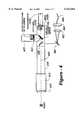
- FIG. 4is a schematic of an optical monitoring system which illustrates important features of a feedback controller of the invention
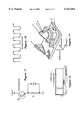
- FIG. 5is a schematic view of a molten pool, an optical axis, a mask, and the orientation of a phototransistor of the invention for sensing dimension;
- FIG. 6is similar to FIG. 5, except that the sensing condition indicating whether distortion is occurring is reversed relative to that of FIG. 5, as are the mask and arrangement of the mask with respect to the deposited material;
- FIG. 7is an electrical circuit diagram of a phototransistor biasing arrangement
- FIG. 8ais an analog voltage signal for the laser before conditioning and control by the feedback system
- FIG. 8bshows voltage drop across the transistor circuit as the result of height of deposit sensing
- FIG. 8c curveshows the digitized signal from the phototransistor sent to control the laser
- FIG. 8dshows the modified analog signal sent to the laser which affects the pulse duration and resultant power of the laser
- FIG. 9illustrates a specific example of a monolithic structure formed by laser cladding on a substrate
- FIG. 10is a graph of a preferred stitching pattern
- FIG. 11is a perspective view of a benchmark sample including numbered residual stress management data points proposed by an international group of users.
- FIG. 12is an illustration of a tool die having core and cavity parts prepared according to a method of the invention.
- the present inventionresides in methods and apparatus for monitoring and controlling the deposition of material on a substrate, typically a metal.
- the inventionis applicable to processes based on the formation/sustaining of molten pool by localized laser heating, and the concurrent injection of powder, typically of metal.
- the materials of the substrate and injected streamare joined to form a deposit.
- at least one dimension of the depositis monitored and controlled to provide a completed workpiece having a desired contour and dimensions within close tolerance.
- the size of the depositis proportional to the amount of the second material injected into the melt-pool.
- the unique monitoring and control assembly of the inventioncomprises a feedback controller which senses a dimension of the deposit and varies the pulse duration of the laser beam based on the detected dimension.
- the height of the depositis sensed and power of the laser beam is controlled inversely with the height of the deposit.
- the present inventioncombines direct metal deposition techniques along with automated direct feedback control to achieve a final product to within close tolerances and having acceptable metallurgical properties.
- the inventioncouples direct metal deposition (DMD) techniques with effective control to build parts, prototypes, molds and dies to close tolerances with complex geometries and good metallurgical characteristics.
- DMDdirect metal deposition
- the inventionalso provides the ability to couple a CAD data base with direct metal deposition whereby a complete part may be fabricated with desired properties within a short period of time, and in an automated system with limited human intervention.
- FIG. 1is a schematic of a direct metal deposition system 102 which includes a novel feedback controller 104 of the invention and a CAD/CAM system 106 for automated production of parts.
- the factors considered to affect the dimensions of material depositioninclude laser power, beam diameter, temporal and spatial distribution of the beam, interaction time, and powder flow rate.
- the feedback controller 104 of the inventionpreferably cooperates directly with the numerical controller (NC) 108 which, itself, controls all functions of the system, including laser power.
- NCnumerical controller
- the systemcomprises a laser source 110 having an appropriate beam focusing means 112.
- the laser sourceis mounted above the substrate or workpiece in order to focus the beam thereon.
- the workpiece substrateis carried on the work table, though any of a number of variety of arrangements may be used to cause relative movement between the workpiece substrate and the laser spray nozzle.
- the systemalso includes a work table 114, power supply 116 and chiller 118 to cool the laser.
- the laser sourcebe a continuous-wave or pulse CO 2 , YAG, or any other wavelength laser having a power density enough to melt the material to be deposited.
- an RF-excited laser or high-power CO 2 laseris used.
- the laser beamis directed roughly perpendicular to the surface of the substrate workpiece.
- the systemincludes a nozzle assembly 202 which operates on the workpiece to apply a cladding layer by injecting powdered metal into the beam.
- Laser and nozzle assemblies of this kindare described in U.S. Pat. Nos. 5,241,419 (Pratt, et al); 5,453,329 (Everett, et al); and 5,477,026 (Buongiomo).
- a suitable laser spray nozzleis available from Quantum Laser Corporation of Norcross, Ga., and is as described in U.S. Pat. No. 4,724,299.
- the laser spray nozzle assemblyincludes a nozzle body with first and second spaced-apart end portions, as described in U.S. Pat. No. 4,724,299.
- a beam passagewayextends between the end portions and permits a laser beam to pass therethrough.
- a housing which surrounds the second end portionis spaced from the second end portion so as to form an annular passage.
- the housinghas an opening coaxial with the beam passageway for permitting the laser beam to pass therethrough.
- a cladding powder supply systemis operably associated with the passage for supplying cladding powder thereto so that the powder exits the opening coaxial with the beam.
- the laser spray nozzle of the inventionachieves uniform clad composition because the beam exits the nozzle substantially coaxially with the cladding powder, both having the same focal point.
- the nozzlehas a common outlet for the beam and the power so that both are consistently directed at the same point on the article. In this way, a common focal point is achieved which assures uniform clad composition.
- Similar resultscan also be obtained by side injection nozzle, however, side injection nozzle restricts the direction of clad movement whereas a concentric nozzle will allow change of direction of deposition at any instant.
- Utilization of a robot in conjunction with a laser cladding systemhelps toward means for achieving a uniform clad.
- the articlemay remain fixed in space and the nozzle may therefore move relative to the article in cooperation with movement of the robot arm.
- the nozzlemay remain fixed and the article moved by the robot.
- the numerical controller 108preferably controls all operating components of the assembly of FIG. 1, including the conditions of operation of the laser, accepting direction from the CAD/CAM computer 106 for building the article, part or workpiece.
- the NC controlleralso receives feedback control signals from the feedback controller to adjust laser power output, and further controlling the relative position of the work table and the laser spray nozzle assembly.
- a numerical controller such as that utilized in FIG. 1is obtainable from a number of vendors including FANUC, Allen Bradley, IGM, etc.
- the CAD/CAM systemis of a conventional type and may comprise a work station supplied by any commercial vendor such as Sun Microsystems, Silicon Graphics, or Hewlett Packard.
- Among the features required of the CAD/CAM softwareis its ability to generate a path across the substrate for material deposition. This makes is possible to execute rapid prototyping and form a solid three-dimensional object directly from CAD dimensions, including the production of direct metal prototypes utilizing the laser spray nozzle.
- the laser spray nozzle 202forms a melt-pool 204 on a substrate article 206.
- Powderis preferably injected through a nozzle 208 around the laser beam 205.
- the laser beam projection on the substrate surfacenot be Gaussian profile.
- the laser beam projectionbe of a relatively general doughnut shape with maximum intensity occurring peripherally.
- the midpoint of the beam profilehas a lower intensity. This provides a melt-pool of relatively uniform temperature distribution.
- other spatial distributions of the laser beamcan be adapted for the process.
- FIG. 3shows a schematic of a direct metal deposition system including a feedback control device 302.
- the energy delivered from the laseris shown by a large arrow, and a small arrow shows powder being delivered into the powder delivery system.
- Chilled water 306is shown being delivered to the outlet of the laser spray nozzle.
- the feedback unit 302is preferably disposed directly adjacent to the point where the laser and powder are incident on the surface of the workpiece 310.
- FIG. 4is a schematic of an optical monitoring system which illustrates the fundamental physics of the feedback control system.
- a dimensionsuch as the height of a laser-clad molten pool is monitored optically and controlled electronically.
- the high temperature molten surface of the molten poolemits with intensity in the infrared region.
- the stick figure of FIG. 4schematically represents the molten pool.
- a narrow band-pass filter 410preferably in the infrared, is placed in front of a camera lens 412.
- the exemplary cameracomprises a 135 mm focal length with the only requirement being suitable magnification of the molten pool.
- the imageis passed through barrel extenders 416, after which a portion of the image (approximately 10 percent) is reflected to an active focal plane of a TV camera 420.
- the reflected imagepreferably passes through a neutral density filter 422 placed between the reflector and the active focal plane of the TV camera.
- the transmissive portion of the optical imagepasses through the reflector, and the magnified image is masked at a focal plane to provide spatial resolution.
- the image exiting the mask 426passes through a lens 428 and then to a light-sensitive device such as phototransistor 430.
- the optical axis 440 angle and the magnification of this optical trainare arranged such that small changes in the height of the clad can be distinguished by the phototransistor 430.
- the sensitivity between the two conditionsis preferably less than 0.010" (ten thousandths (10/1000") of an inch. That is, the threshold sensitivity between the two conditions is ⁇ 0.010"; the window of "unmasked” condition is ⁇ 0.100" before returning to masked" condition.
- FIG. 4also illustrates a way in which spectroscopic analysis may be incorporated into the invention through the use of a beamsplitter or partially transmitting mirror 450, which directs a portion of the light received from the object to a dispersive element 460 such as a diffraction grating, the light from which may be collimated by a lens 462 and fed to a detector 464 outputting spectral content information along line 466.
- spectral content informationmay be used to passively monitor and/or record data regarding the material composition of the melt-pool or cladding layer as it develops or, may be incorporated into a feedback loop to alter the operation of the system in accordance with material composition.
- the constituency of the powder feedmay be varied in accordance with design criteria and checked through the spectral analysis aspect to ensure that the proper alloy or change in material composition is taking place.
- laser poweris preferably the variable modified in accordance with a stored program
- other variablesmay be used separately or in conjunction with laser power.
- the progression of the laser spot, or the size of the laser spotmay be varied to meet the design criteria or, alternatively, material feed may be adjusted.
- material removalis also made possible by the invention along with material build-up, enabling mistakes or imperfections to be corrected on-the-fly, or, alternatively, enabling the modification of pre-existing parts with respect to new design criteria.
- the phototransistor signalis processed by a circuit which controls laser power.
- Most laserspossess the ability to be controlled by a single analog voltage signal, for example 0 volts and 12 volts will correspond to no-power, and full-power, respectively. Any voltage in between will generate a corresponding output power. Most lasers can respond to this analog voltage within a millisecond.
- a schematic of a molten deposit 502is shown with a mask 504 disposed between the deposit and the phototransistor 506.
- the maskis in planar form and is a solid with a hole through which light may pass.
- the height of the cladreaches a predetermined level, light in the form of the selected wavelength from the material of the deposit passes through the mask and is incident on the phototransistor, as shown.
- the level of the depositis below the hole in the mask, light will not be incident on the phototransistor. This condition, between light and no light, can be used to control and adjust operation of the laser.
- FIG. 8is a series of curves showing the relationship of signals controlling laser operation, phototransistor response to light/no light condition in the form of voltage drop, and how the phototransistor signal controls laser power.
- the horizontal axisrepresents time
- the vertical axisrepresents voltage.
- the first of curve of FIG. 8ashows an analog voltage signal for the laser before any conditioning and control by the feedback system of the invention.
- the second of FIG. 8bshows the voltage drop across the phototransistor resistor.
- the analog voltage for the laserbefore any control by the feedback system, is consistent and unadjusted with time.
- the voltage drop across the phototransistor resistor of FIG. 7is shown during the cladding operation.
- the impedance of the phototransistoris high, signifying that it is not sensing light emitted from the molten surface and transmitted through the selective narrow band-pass filter.
- the voltage drop across the phototransistor resistoris relatively low.
- the peak voltage drop across the phototransistorprovides a signal which is digitized.
- the fourth curve of FIG. 8dshows that the digitized signal has now modified the actual signal sent to the laser and affects the pulse duration and resultant power of the laser.
- the voltage over time for the laserhas now been adjusted corresponding to the phototransistor's voltage drop and sending of the monitored incident wavelength of light.
- the phototransistorsends a signal to the numerical controller of FIG. 1, which then adjusts voltage supply to the laser, controlling laser power, and finally adjusting laser duration incident on the workpiece substrate.
- the voltage of the analog signalcorresponds to laser power.
- the feedback systemthus controls the accumulative dimensions of the workpiece.
- the feedback controller of the inventionessentially tells the laser that if the workpiece is going off dimension, then the duration of "beam on" time for each pulse is to be reduced. When the beam is on, deposition occurs. If the particular location is too high, the feedback loop cuts off the laser power and greatly reduces deposition.
- the automated control and adjustment of the inventionare critical since manual adjustments are not effective.
- the systemmay be used to deposit material, pixel by pixel. Without the feedback control, after several minutes or the accumulation of several layers the workpiece may become distorted, after which further deterioration of conditions may lead to distortion and destruction.
- the advantage of the feedback control system of the inventionis that before distortion can occur, the phototransistor senses the condition of light/no light emitted at the unique wavelength of the workpiece material, and a computer is preprogrammed to reduce deposition until the feedback controller senses an acceptable condition where it permits pulses to extend their full amount.
- a Chromium-Molybdenum hot work die steel, H13was directly deposited onto substrates of wrought H13.
- This alloycommonly used to die casting, was analyzed because of its potential, high-volume usefulness in the rapid-manufacturing of die casting tooling.
- Heat treat comparisons for both DMD and wrought H13were performed in the following areas: 1) as clad hardness, ductility, and microstructure, 2) initial tempering response, and 3) tempering response for austenitized (at 1010° C.), oil-quenched material.
- the operating conditions used for coarse claddingconsisted of a 1.1 mm focus spot rastered to 3.5 mm for the fabrication of a thick, 1-D, vertical wall.
- the laser powerwas 4500 watts and powder feed rate was 16 gm/min.
- the powderwas delivered perpendicular to the raster direction.
- the beam and the powder flowwere turned off at the end of each pass and subsequent layers were accumulated while translating 750 mm/min in the same direction.
- Successive layerswere deposited to create a 3.5 mm wide, 70 mm tall, and 120 mm long build-up onto a low carbon steel substrate.
- the temperature of the cladwas not measured, but visible radiation was observed after the first 5-10 layers were deposited.
- a tensile bar oriented perpendicular to the clad directionwas machined from this "as-clad" specimen, as shown in FIG. 9. During tensile testing, an extensometer measured strain in the gage section.
- the metal powder and shroud gaswere delivered concentrically.
- the molten poolwas formed by a 0.6 mm diameter spot.
- the specimen velocity for both types of cladding processeswas 750 mm/min.
- the laser power and powder feed ratewere 1000 watts and 5 gm/min for the fine processing.
- a feedback systemmonitored the height of the molten pool as the specimen was traversed in a stitching pattern as shown in FIG. 10. The thickness of each deposited layer was 250 microns. The pattern was repeated to create a slab 90 mm high. H13 was used for both the substrate and clad to allow a direct comparison between the laser-clad and wrought material in the ensuing heat treating experiments.
- FIG. 11also shows the points where stress was measured. Locations 2, 6 & 5 were deposited during the last run and thus shows residual compressive stress, since they were not stress relieved. Other locations, deposited in earlier runs and subsequently stress relieved, showed negligible residual stress, whereas the maximum stress at the location without stress relieving is +49.4 KSI.
- Injection molding dies with imbedded copper chill block and a water-cooling channelwere prepared, and a trimming die was also fabricated. These components had very close dimensional accuracy, all with dimensional tolerance of a few thousandths of an inch. These examples show the feasibility of DMD process for successful fabrication of three-dimensional components with H13 alloy. The process is capable of controlling the microstructure and thus properties by carefully controlling process parameters. Heat treatment response of the laser deposited component and a wrought H13 steel component are the same. In fact, heat treated laser clad H13 is more structurally homogeneous than wrought H13.
- the methods and apparatus of the inventionprovide the ability to establish and refine components of almost any geometry that can be produced from computer database.
- Another applicationis for user-specific low volume parts production, where a small quantity can be produced in a cost-effective way. This is particularly advantageous for fabrication of medical devices, such as artificial prosthetic parts for individuals.
- Other potential applicationsinclude molds for polymer injection/fabrication, inserts for Al die casting molds with greatly reduced turnaround times, and layer glazing.
- the inventionprovides the ability to control composition, microstructure, residual stresses, and mechanical properties.
- the systemis capable of "lights off” manufacturing utilizing a feedback loop for process control and integrating hardware and software in the feedback control loop sensor for automated operation.
- Mathematical modelingis easily developed for different materials used in the process.
- Other featuresmay easily be integrated into the system, including piezoelectric and electrical sensors for measurement of residual stress accumulation, strain and stress-induced distortion, and to monitor crack initiation.
Landscapes
- Engineering & Computer Science (AREA)
- Chemical & Material Sciences (AREA)
- Manufacturing & Machinery (AREA)
- Materials Engineering (AREA)
- Physics & Mathematics (AREA)
- Optics & Photonics (AREA)
- Mechanical Engineering (AREA)
- Health & Medical Sciences (AREA)
- General Health & Medical Sciences (AREA)
- Toxicology (AREA)
- Automation & Control Theory (AREA)
- Plasma & Fusion (AREA)
- Analytical Chemistry (AREA)
- Business, Economics & Management (AREA)
- Strategic Management (AREA)
- Human Resources & Organizations (AREA)
- Marketing (AREA)
- Primary Health Care (AREA)
- Economics (AREA)
- Tourism & Hospitality (AREA)
- General Business, Economics & Management (AREA)
- General Physics & Mathematics (AREA)
- Theoretical Computer Science (AREA)
- Laser Beam Processing (AREA)
- Powder Metallurgy (AREA)
- Chemical Vapour Deposition (AREA)
- Other Surface Treatments For Metallic Materials (AREA)
Abstract
Description
Claims (25)
Priority Applications (20)
| Application Number | Priority Date | Filing Date | Title |
|---|---|---|---|
| US09/107,912US6122564A (en) | 1998-06-30 | 1998-06-30 | Apparatus and methods for monitoring and controlling multi-layer laser cladding |
| ES99930524.6TES2459601T3 (en) | 1998-06-30 | 1999-06-22 | Apparatus for laser coating |
| PCT/US1999/014031WO2000000921A1 (en) | 1998-06-30 | 1999-06-22 | Apparatus and methods for laser cladding |
| KR1020007014994AKR100606476B1 (en) | 1998-06-30 | 1999-06-22 | Laser Cladding Apparatus and Method |
| CNB998092746ACN1205582C (en) | 1998-06-30 | 1999-06-22 | Laser cladding apparatus and method |
| JP2000557422AJP2002519200A (en) | 1998-06-30 | 1999-06-22 | Laser cladding apparatus and method |
| CA002336583ACA2336583C (en) | 1998-06-30 | 1999-06-22 | Apparatus and methods for laser cladding |
| BRPI9912231ABRPI9912231B1 (en) | 1998-06-30 | 1999-06-22 | "System for automatically controlling layering of a material on a substrate and method of manufacturing an article" |
| RU2001102604/02ARU2228243C2 (en) | 1998-06-30 | 1999-06-22 | Method and apparatus for laser surfacing |
| AU47049/99AAU754346B2 (en) | 1998-06-30 | 1999-06-22 | Apparatus and methods for laser cladding |
| EP99930524.6AEP1099184B1 (en) | 1998-06-30 | 1999-06-22 | Apparatus for laser cladding |
| US09/526,631US6937921B1 (en) | 1998-06-30 | 2000-03-16 | Production of smart dies and molds using direct metal deposition |
| US09/570,986US6410105B1 (en) | 1998-06-30 | 2000-05-15 | Production of overhang, undercut, and cavity structures using direct metal depostion |
| US09/608,874US7286893B1 (en) | 1998-06-30 | 2000-06-30 | Tailoring residual stress and hardness during direct metal deposition |
| US09/670,670US6472029B1 (en) | 1998-06-30 | 2000-09-27 | Fabrication of laminate structures using direct metal deposition |
| US09/671,538US6925346B1 (en) | 1998-06-30 | 2000-09-27 | Closed-loop, rapid manufacturing of three-dimensional components using direct metal deposition |
| NO20006700ANO20006700L (en) | 1998-06-30 | 2000-12-29 | Laser coating device and method |
| US09/916,566US7765022B2 (en) | 1998-06-30 | 2001-07-27 | Direct metal deposition apparatus utilizing rapid-response diode laser source |
| US11/140,752US8062715B2 (en) | 1998-06-30 | 2005-05-31 | Fabrication of alloy variant structures using direct metal deposition |
| JP2011106871AJP2011167768A (en) | 1998-06-30 | 2011-05-12 | Apparatus and method for laser cladding |
Applications Claiming Priority (1)
| Application Number | Priority Date | Filing Date | Title |
|---|---|---|---|
| US09/107,912US6122564A (en) | 1998-06-30 | 1998-06-30 | Apparatus and methods for monitoring and controlling multi-layer laser cladding |
Related Child Applications (4)
| Application Number | Title | Priority Date | Filing Date |
|---|---|---|---|
| US09/526,631Continuation-In-PartUS6937921B1 (en) | 1998-06-30 | 2000-03-16 | Production of smart dies and molds using direct metal deposition |
| US09/570,986Continuation-In-PartUS6410105B1 (en) | 1998-06-30 | 2000-05-15 | Production of overhang, undercut, and cavity structures using direct metal depostion |
| US09/608,874Continuation-In-PartUS7286893B1 (en) | 1998-06-30 | 2000-06-30 | Tailoring residual stress and hardness during direct metal deposition |
| US09/916,566Continuation-In-PartUS7765022B2 (en) | 1998-06-30 | 2001-07-27 | Direct metal deposition apparatus utilizing rapid-response diode laser source |
Publications (1)
| Publication Number | Publication Date |
|---|---|
| US6122564Atrue US6122564A (en) | 2000-09-19 |
Family
ID=22319128
Family Applications (1)
| Application Number | Title | Priority Date | Filing Date |
|---|---|---|---|
| US09/107,912Expired - LifetimeUS6122564A (en) | 1998-06-30 | 1998-06-30 | Apparatus and methods for monitoring and controlling multi-layer laser cladding |
Country Status (12)
| Country | Link |
|---|---|
| US (1) | US6122564A (en) |
| EP (1) | EP1099184B1 (en) |
| JP (2) | JP2002519200A (en) |
| KR (1) | KR100606476B1 (en) |
| CN (1) | CN1205582C (en) |
| AU (1) | AU754346B2 (en) |
| BR (1) | BRPI9912231B1 (en) |
| CA (1) | CA2336583C (en) |
| ES (1) | ES2459601T3 (en) |
| NO (1) | NO20006700L (en) |
| RU (1) | RU2228243C2 (en) |
| WO (1) | WO2000000921A1 (en) |
Cited By (186)
| Publication number | Priority date | Publication date | Assignee | Title |
|---|---|---|---|---|
| US20020082741A1 (en)* | 2000-07-27 | 2002-06-27 | Jyoti Mazumder | Fabrication of biomedical implants using direct metal deposition |
| US6423926B1 (en) | 2000-11-16 | 2002-07-23 | Joseph K. Kelly | Direct-metal-deposition (DMD) nozzle fault detection using temperature measurements |
| US6459951B1 (en) | 1999-09-10 | 2002-10-01 | Sandia Corporation | Direct laser additive fabrication system with image feedback control |
| US20020152002A1 (en)* | 2001-02-21 | 2002-10-17 | Markus Lindemann | Process and device for producing a shaped body by selective laser melting |
| US6472029B1 (en)* | 1998-06-30 | 2002-10-29 | The P.O.M. Group | Fabrication of laminate structures using direct metal deposition |
| US6518541B1 (en)* | 1999-11-16 | 2003-02-11 | Joseph K. Kelly | Duty cycle stabilization in direct metal deposition (DMD) systems |
| US6534745B1 (en) | 1999-09-27 | 2003-03-18 | Mathew T. J. Lowney | Nozzle particularly suited to direct metal deposition |
| WO2003042895A1 (en)* | 2001-11-17 | 2003-05-22 | Insstek Inc. | Method and system for real-time monitoring and controlling height of deposit by using image photographing and image processing technology in laser cladding and laser-aided direct metal manufacturing process |
| US6605795B1 (en)* | 1999-11-04 | 2003-08-12 | Mts Systems Corporation | Control system for depositing powder to a molten puddle |
| US6676892B2 (en) | 2000-06-01 | 2004-01-13 | Board Of Regents, University Texas System | Direct selective laser sintering of metals |
| WO2004011185A1 (en)* | 2002-07-26 | 2004-02-05 | Honeywell International Inc. | Powder feed splitter for hand-held laser powder fusion welding torch |
| US20040020625A1 (en)* | 2002-07-29 | 2004-02-05 | Jyoti Mazumder | Fabrication of customized die inserts using closed-loop direct metal deposition (DMD) |
| EP1396556A1 (en)* | 2002-09-06 | 2004-03-10 | ALSTOM (Switzerland) Ltd | Method for controlling the microstructure of a laser metal formed hard layer |
| WO2004020139A1 (en)* | 2002-08-28 | 2004-03-11 | The P.O.M. Group | Part-geometry independant real time closed loop weld pool temperature control system for multi-layer dmd process |
| US6710280B2 (en)* | 2001-05-22 | 2004-03-23 | The P.O.M. Group | Focusing optics for adaptive deposition in rapid manufacturing |
| US6745609B2 (en) | 2002-11-06 | 2004-06-08 | Daimlerchrysler Corporation | Sheet metal forming die assembly with textured die surfaces |
| US6751516B1 (en)* | 2000-08-10 | 2004-06-15 | Richardson Technologies, Inc. | Method and system for direct writing, editing and transmitting a three dimensional part and imaging systems therefor |
| US20040133298A1 (en)* | 2002-10-31 | 2004-07-08 | Ehsan Toyserkani | System and method for closed-loop control of laser cladding by powder injection |
| US6793140B2 (en)* | 2001-01-10 | 2004-09-21 | The P.O.M. Group | Machine-readable code generation using direct metal deposition |
| US20050023256A1 (en)* | 2003-07-31 | 2005-02-03 | Srikanth Sankaranarayanan | 3-D adaptive laser powder fusion welding |
| US20050031892A1 (en)* | 2003-02-21 | 2005-02-10 | Jyoti Mazumder | Wear-resistant alloys particularly suited to aluminum-engine head-valve seats |
| US20050038551A1 (en)* | 2002-08-29 | 2005-02-17 | Jyoti Mazumder | Method of fabricating composite tooling using closed-loop direct-metal deposition |
| US20050056628A1 (en)* | 2003-09-16 | 2005-03-17 | Yiping Hu | Coaxial nozzle design for laser cladding/welding process |
| US20050123672A1 (en)* | 2003-12-03 | 2005-06-09 | Justin Daniel F. | Laser based metal deposition of implant structures |
| US20050155738A1 (en)* | 2003-11-06 | 2005-07-21 | Squires Wayne F. | Device and method for cooling a shot plug |
| US6925346B1 (en) | 1998-06-30 | 2005-08-02 | Jyoti Mazumder | Closed-loop, rapid manufacturing of three-dimensional components using direct metal deposition |
| US6937921B1 (en)* | 1998-06-30 | 2005-08-30 | Precision Optical Manufacturing (Pom) | Production of smart dies and molds using direct metal deposition |
| US6940037B1 (en) | 2003-08-25 | 2005-09-06 | Southern Methodist University | System and method for controlling welding parameters in welding-based deposition processes |
| US20050212694A1 (en)* | 2004-03-26 | 2005-09-29 | Chun-Ta Chen | Data distribution method and system |
| US20050224209A1 (en)* | 1998-06-30 | 2005-10-13 | Skszek Timothy W | Fabrication of alloy variant structures using direct metal deposition |
| US6995334B1 (en)* | 2003-08-25 | 2006-02-07 | Southern Methodist University | System and method for controlling the size of the molten pool in laser-based additive manufacturing |
| US20060060467A1 (en)* | 2004-09-18 | 2006-03-23 | Daniel Clark | Component coating |
| US7020539B1 (en) | 2002-10-01 | 2006-03-28 | Southern Methodist University | System and method for fabricating or repairing a part |
| US7045738B1 (en) | 2002-10-01 | 2006-05-16 | Southern Methodist University | Powder delivery system and method |
| US20060228248A1 (en)* | 2002-12-19 | 2006-10-12 | Arcam Ab | Arrangement and method for production of a three dimensional object |
| US20070062920A1 (en)* | 2005-09-07 | 2007-03-22 | Shin Yung C | Laser assisted machining process with distributed lasers |
| US20070202351A1 (en)* | 2003-12-03 | 2007-08-30 | Justin Daniel F | Laser based metal deposition (LBMD) of implant structures |
| US20070205184A1 (en)* | 2006-01-30 | 2007-09-06 | Jyoti Mazumder | High-speed, ultra precision manufacturing station that combines direct metal deposition and edm |
| US20080029495A1 (en)* | 2004-04-17 | 2008-02-07 | Mtu Aero Engines Gmbh | Method and Device for Laser Welding of Components Made from Super Alloys |
| US20080149313A1 (en)* | 2006-12-20 | 2008-06-26 | Victor Blakemore Slaughter | Method of making a heat exchanger |
| US20080149304A1 (en)* | 2006-12-20 | 2008-06-26 | Victor Blakemore Slaughter | Method of making a heat exchanger core component |
| US20080149299A1 (en)* | 2006-12-20 | 2008-06-26 | Victor Blakemore Slaughter | Method of using minimal surfaces and minimal skeletons to make heat exchanger components |
| US20080178994A1 (en)* | 2007-01-31 | 2008-07-31 | General Electric Company | Laser net shape manufacturing using an adaptive toolpath deposition method |
| US20080223832A1 (en)* | 2006-11-16 | 2008-09-18 | Lijun Song | Real time implementation of generalized predictive control algorithm for the control of direct metal deposition (dmd) process |
| US20080260964A1 (en)* | 2007-04-17 | 2008-10-23 | Vijayavel Bagavath-Singh | Vision system and method for direct-metal-deposition (dmd) tool-path generation |
| US20080296270A1 (en)* | 2007-05-31 | 2008-12-04 | Lijun Song | Real-time implementation of generalized predictive algorithm for direct metal deposition (dmd) process control |
| WO2008154045A1 (en)* | 2007-06-12 | 2008-12-18 | Rolls-Royce Corporation | System, methods, and apparatus for repair of components |
| US20080314878A1 (en)* | 2007-06-22 | 2008-12-25 | General Electric Company | Apparatus and method for controlling a machining system |
| US20090001058A1 (en)* | 2007-06-27 | 2009-01-01 | James Lentz | Method and apparatus for depositing raised features at select locations on a substrate to produce a slip-resistant surface |
| US7586061B2 (en) | 2002-02-20 | 2009-09-08 | Alstom Technology Ltd. | Method of controlled remelting of or laser metal forming on the surface of an article |
| US20090326671A1 (en)* | 2006-10-13 | 2009-12-31 | Symmetry Medical Inc. | Medical devices |
| US20100234977A1 (en)* | 2009-03-16 | 2010-09-16 | The Boeing Company | Controlling Cutting of Continuously Fabricated Composite Parts with Nondestructive Evaluation |
| US7827883B1 (en)* | 1996-02-16 | 2010-11-09 | Bernal, Inc. | Cutting die and method of forming |
| WO2011028074A2 (en) | 2009-09-04 | 2011-03-10 | Insstek, Inc. | Cutting/polishing tool and manufacturing method thereof |
| US7931683B2 (en) | 2007-07-27 | 2011-04-26 | Boston Scientific Scimed, Inc. | Articles having ceramic coated surfaces |
| US7938855B2 (en) | 2007-11-02 | 2011-05-10 | Boston Scientific Scimed, Inc. | Deformable underlayer for stent |
| US7942926B2 (en) | 2007-07-11 | 2011-05-17 | Boston Scientific Scimed, Inc. | Endoprosthesis coating |
| US7951412B2 (en) | 2006-06-07 | 2011-05-31 | Medicinelodge Inc. | Laser based metal deposition (LBMD) of antimicrobials to implant surfaces |
| US20110135952A1 (en)* | 2009-12-04 | 2011-06-09 | Honeywell International Inc. | Turbine components for engines and methods of fabricating the same |
| US7976915B2 (en) | 2007-05-23 | 2011-07-12 | Boston Scientific Scimed, Inc. | Endoprosthesis with select ceramic morphology |
| US7981150B2 (en) | 2006-11-09 | 2011-07-19 | Boston Scientific Scimed, Inc. | Endoprosthesis with coatings |
| CN102133698A (en)* | 2011-02-17 | 2011-07-27 | 中国航空工业集团公司西安飞机设计研究所 | Method for manufacturing airplane metal integrated structure |
| US8002823B2 (en) | 2007-07-11 | 2011-08-23 | Boston Scientific Scimed, Inc. | Endoprosthesis coating |
| US8029554B2 (en) | 2007-11-02 | 2011-10-04 | Boston Scientific Scimed, Inc. | Stent with embedded material |
| US20110259862A1 (en)* | 2008-09-05 | 2011-10-27 | Mtt Technologies Limited | Additive Manufacturing Apparatus with a Chamber and a Removably-Mountable Optical Module; Method of Preparing a Laser Processing Apparatus with such Removably-Mountable Optical Module |
| US8067054B2 (en) | 2007-04-05 | 2011-11-29 | Boston Scientific Scimed, Inc. | Stents with ceramic drug reservoir layer and methods of making and using the same |
| US8066763B2 (en) | 1998-04-11 | 2011-11-29 | Boston Scientific Scimed, Inc. | Drug-releasing stent with ceramic-containing layer |
| US8070797B2 (en) | 2007-03-01 | 2011-12-06 | Boston Scientific Scimed, Inc. | Medical device with a porous surface for delivery of a therapeutic agent |
| US8071156B2 (en) | 2009-03-04 | 2011-12-06 | Boston Scientific Scimed, Inc. | Endoprostheses |
| US20110300306A1 (en)* | 2009-12-04 | 2011-12-08 | The Regents Of The University Of Michigan | Coaxial laser assisted cold spray nozzle |
| US8117985B2 (en) | 2007-10-10 | 2012-02-21 | Ronald Peter Whitfield | Laser cladding device with an improved nozzle |
| US20120131056A1 (en)* | 2010-11-22 | 2012-05-24 | Yasuo Matsuoka | Drop recipe creating method, database creating method and medium |
| US8187620B2 (en) | 2006-03-27 | 2012-05-29 | Boston Scientific Scimed, Inc. | Medical devices comprising a porous metal oxide or metal material and a polymer coating for delivering therapeutic agents |
| US8216632B2 (en) | 2007-11-02 | 2012-07-10 | Boston Scientific Scimed, Inc. | Endoprosthesis coating |
| US8221822B2 (en) | 2007-07-31 | 2012-07-17 | Boston Scientific Scimed, Inc. | Medical device coating by laser cladding |
| US8231980B2 (en) | 2008-12-03 | 2012-07-31 | Boston Scientific Scimed, Inc. | Medical implants including iridium oxide |
| WO2012100766A1 (en)* | 2011-01-28 | 2012-08-02 | Mtu Aero Engines Gmbh | Method and device for process monitoring |
| US20120217226A1 (en)* | 2009-10-31 | 2012-08-30 | Mtu Aero Engines Gmbh | Method and device for producing a component of a turbomachine |
| US8287937B2 (en) | 2009-04-24 | 2012-10-16 | Boston Scientific Scimed, Inc. | Endoprosthese |
| US20120267348A1 (en)* | 2006-05-01 | 2012-10-25 | Tcz Llc | Systems and method for optimization of laser beam spatial intensity profile |
| US8353949B2 (en) | 2006-09-14 | 2013-01-15 | Boston Scientific Scimed, Inc. | Medical devices with drug-eluting coating |
| US20130097050A1 (en)* | 2009-05-19 | 2013-04-18 | Peter L. Soracco | Method and system for sales of golf equipment |
| US8431149B2 (en) | 2007-03-01 | 2013-04-30 | Boston Scientific Scimed, Inc. | Coated medical devices for abluminal drug delivery |
| US8449603B2 (en) | 2008-06-18 | 2013-05-28 | Boston Scientific Scimed, Inc. | Endoprosthesis coating |
| WO2013155591A1 (en)* | 2012-04-16 | 2013-10-24 | Magna International Inc. | Process for laser-assisted tool build and repair |
| US8574615B2 (en) | 2006-03-24 | 2013-11-05 | Boston Scientific Scimed, Inc. | Medical devices having nanoporous coatings for controlled therapeutic agent delivery |
| US20130295300A1 (en)* | 2010-11-19 | 2013-11-07 | Pilkington Group Limited | Glazing with frequency selective coating |
| US8604381B1 (en) | 2006-10-12 | 2013-12-10 | Purdue Research Foundation | Integrated laser material processing cell |
| US20140154088A1 (en)* | 2012-12-01 | 2014-06-05 | Alstom Technology Ltd. | Method for manufacturing a metallic component by additive laser manufacturing |
| US8771343B2 (en) | 2006-06-29 | 2014-07-08 | Boston Scientific Scimed, Inc. | Medical devices with selective titanium oxide coatings |
| US20140202997A1 (en)* | 2013-01-24 | 2014-07-24 | Wisconsin Alumni Research Foundation | Reducing surface asperities |
| US20140209584A1 (en)* | 2013-01-25 | 2014-07-31 | Hon Hai Precision Industry Co., Ltd. | Laser machining device |
| US8800480B2 (en) | 2007-10-10 | 2014-08-12 | Ronald Peter Whitfield | Laser cladding device with an improved nozzle |
| US8815275B2 (en) | 2006-06-28 | 2014-08-26 | Boston Scientific Scimed, Inc. | Coatings for medical devices comprising a therapeutic agent and a metallic material |
| US8815273B2 (en) | 2007-07-27 | 2014-08-26 | Boston Scientific Scimed, Inc. | Drug eluting medical devices having porous layers |
| US8900292B2 (en) | 2007-08-03 | 2014-12-02 | Boston Scientific Scimed, Inc. | Coating for medical device having increased surface area |
| US8920491B2 (en) | 2008-04-22 | 2014-12-30 | Boston Scientific Scimed, Inc. | Medical devices having a coating of inorganic material |
| US8932346B2 (en) | 2008-04-24 | 2015-01-13 | Boston Scientific Scimed, Inc. | Medical devices having inorganic particle layers |
| US9095994B2 (en) | 2011-08-09 | 2015-08-04 | GM Global Technology Operations LLC | Method for applying variable magnetic properties to a induction heated tool face and manufacturing parts using the tool |
| DE102014212246B3 (en)* | 2014-06-26 | 2015-08-06 | MTU Aero Engines AG | Method and device for quality assurance |
| EP2598313B1 (en) | 2010-07-28 | 2015-08-12 | CL Schutzrechtsverwaltungs GmbH | Method and apparatus for producing a three-dimensional component |
| DE102014208768A1 (en)* | 2014-05-09 | 2015-12-17 | MTU Aero Engines AG | Method and device for quality assurance |
| US9284409B2 (en) | 2007-07-19 | 2016-03-15 | Boston Scientific Scimed, Inc. | Endoprosthesis having a non-fouling surface |
| US20160108516A1 (en)* | 2014-10-17 | 2016-04-21 | Dm3D Technology, Llc | Method of applying metallic layer on substrate and composite article formed thereby |
| US9352420B2 (en) | 2007-10-10 | 2016-05-31 | Ronald Peter Whitfield | Laser cladding device with an improved zozzle |
| US20160151859A1 (en)* | 2014-12-02 | 2016-06-02 | Product Innovation and Engineering L.L.C. | System and method for controlling the input energy from an energy point source during metal processing |
| US20160251745A1 (en)* | 2013-10-29 | 2016-09-01 | General Electric Technology Gmbh | Device for hvof spraying process |
| US9474327B2 (en) | 2013-08-19 | 2016-10-25 | Nike, Inc. | Sole structure masters, sole structure molds and sole structures having indicia and/or texture |
| CN106216678A (en)* | 2016-09-29 | 2016-12-14 | 苏州大学 | Laser forming uniformly uprises the method for part |
| US9539681B2 (en) | 2011-11-30 | 2017-01-10 | Board Of Trustees Of Northern Illinois University | Laser assisted machining system for ceramics and hard materials |
| US9573226B2 (en) | 2011-10-21 | 2017-02-21 | Surclean, Inc. | System configured for removing a coating from a substrate using electromagnetic radiation |
| US9573224B2 (en) | 2014-09-02 | 2017-02-21 | Product Innovation & Engineering, LLC | System and method for determining beam power level along an additive deposition path |
| US9586289B2 (en) | 2014-04-30 | 2017-03-07 | Alabama Specialty Products, Inc. | Cladding apparatus and method |
| US9650537B2 (en) | 2014-04-14 | 2017-05-16 | Ut-Battelle, Llc | Reactive polymer fused deposition manufacturing |
| US20170189996A1 (en)* | 2014-07-03 | 2017-07-06 | Autotech Engineering A.I.E. | Reinforced structural components |
| US9757902B2 (en) | 2014-09-02 | 2017-09-12 | Product Innovation and Engineering L.L.C. | Additive layering method using improved build description |
| US20170297140A1 (en)* | 2016-04-15 | 2017-10-19 | U.S.A. As Represented By The Administrator Of The National Aeronautics And Space Administration | Process Control of Electron Beam Wire Additive Manufacturing |
| US20170312855A1 (en)* | 2014-10-24 | 2017-11-02 | Laserbond Limited | Method and apparatus for cladding a surface of an article |
| US9873180B2 (en) | 2014-10-17 | 2018-01-23 | Applied Materials, Inc. | CMP pad construction with composite material properties using additive manufacturing processes |
| US9943933B2 (en) | 2013-03-15 | 2018-04-17 | Rolls-Royce Corporation | Repair of gas turbine engine components |
| TWI623412B (en)* | 2014-03-31 | 2018-05-11 | 三菱重工業股份有限公司 | Three-dimensional lamination device and three-dimensional lamination method |
| US9981341B2 (en) | 2014-08-25 | 2018-05-29 | Jyoti Mazumder | Smart additive manufacturing system (SAMS) |
| US10035219B2 (en) | 2016-01-13 | 2018-07-31 | Product Innovation and Engineering L.L.C. | Electrostatic powder feeder |
| US10065201B2 (en) | 2015-11-11 | 2018-09-04 | Technology Research Association For Future Additive Manufacturing | Processing nozzle and optical machining apparatus |
| US20180290241A1 (en)* | 2014-11-21 | 2018-10-11 | Renishaw Plc | Additive manufacturing apparatus and methods |
| US20180290381A1 (en)* | 2015-09-25 | 2018-10-11 | Obschestvo S Ogranichennoy Otvetstvennostyu "Adirut" | Method and device for the additive manufacturing of components |
| US10119195B2 (en) | 2009-12-04 | 2018-11-06 | The Regents Of The University Of Michigan | Multichannel cold spray apparatus |
| US10124531B2 (en) | 2013-12-30 | 2018-11-13 | Ut-Battelle, Llc | Rapid non-contact energy transfer for additive manufacturing driven high intensity electromagnetic fields |
| US10189114B2 (en) | 2009-09-17 | 2019-01-29 | Sciaky, Inc. | Electron beam layer manufacturing |
| US10201877B2 (en) | 2011-10-26 | 2019-02-12 | Titanova Inc | Puddle forming and shaping with primary and secondary lasers |
| US10213797B2 (en) | 2017-02-24 | 2019-02-26 | Powder Motion Labs, LLC | Electrostatic powder feeder |
| US10343031B1 (en) | 2017-10-18 | 2019-07-09 | Cobra Golf Incorporated | Golf club head with openwork rib |
| US10384330B2 (en) | 2014-10-17 | 2019-08-20 | Applied Materials, Inc. | Polishing pads produced by an additive manufacturing process |
| US10391605B2 (en) | 2016-01-19 | 2019-08-27 | Applied Materials, Inc. | Method and apparatus for forming porous advanced polishing pads using an additive manufacturing process |
| US10399201B2 (en) | 2014-10-17 | 2019-09-03 | Applied Materials, Inc. | Advanced polishing pads having compositional gradients by use of an additive manufacturing process |
| US10442133B2 (en)* | 2016-02-17 | 2019-10-15 | Hochschule Fuer Angewandte Wissenschaften Aschaffenburg | Optical method and apparatus for fabricating a structured object |
| US10456983B2 (en) | 2016-03-25 | 2019-10-29 | Technology Research Association For Future Additive Manufacturing | Three-dimensional laminating and shaping apparatus, control method of three-dimensional laminating and shaping apparatus, and control program of three-dimensional laminating and shaping apparatus |
| US10471542B1 (en)* | 2017-06-27 | 2019-11-12 | United States Of America As Represented By The Administrator Of Nasa | Cladding and freeform deposition for coolant channel closeout |
| US10537966B2 (en) | 2015-03-04 | 2020-01-21 | Technology Research Association For Future Additive Manufacturing | Processing nozzle, processing head, machining apparatus, and control method and control program of processing nozzle |
| US10596763B2 (en) | 2017-04-21 | 2020-03-24 | Applied Materials, Inc. | Additive manufacturing with array of energy sources |
| US20200147868A1 (en)* | 2018-11-09 | 2020-05-14 | General Electric Company | Method for Detecting Errors and Compensating for Thermal Dissipation in an Additive Manufacturing Process |
| WO2020114833A1 (en)* | 2018-12-04 | 2020-06-11 | Trumpf Laser- Und Systemtechnik Gmbh | Controlled powder deposit welding method |
| CN111364039A (en)* | 2020-03-26 | 2020-07-03 | 陕西天元智能再制造股份有限公司 | Laser cladding self-adjusting device and method |
| US20200215646A1 (en)* | 2019-01-04 | 2020-07-09 | George H. Lambert | Laser deposition process for a self sharpening knife cutting edge |
| US10722946B2 (en) | 2016-04-25 | 2020-07-28 | Thomas Strangman | Methods of fabricating turbine engine components |
| CN111593341A (en)* | 2020-05-22 | 2020-08-28 | 江苏大学 | A high-performance thermal barrier coating for heavy-duty gas turbine blades and a multi-process combination preparation method thereof |
| US10799975B2 (en) | 2016-02-29 | 2020-10-13 | Rolls-Royce Corporation | Directed energy deposition for processing gas turbine engine components |
| US10800615B2 (en) | 2018-03-16 | 2020-10-13 | Power Motion Labs, LLC | Electrostatic conveyor-wheel powder feeder |
| US10821573B2 (en) | 2014-10-17 | 2020-11-03 | Applied Materials, Inc. | Polishing pads produced by an additive manufacturing process |
| US10836102B2 (en)* | 2015-08-31 | 2020-11-17 | Nederlandse Organisatie Voor Toegepast-Natuurwetenschappelijk Onderzoek Tno | Method and apparatus for layerwise production of a tangible object |
| US10875153B2 (en) | 2014-10-17 | 2020-12-29 | Applied Materials, Inc. | Advanced polishing pad materials and formulations |
| US10875145B2 (en) | 2014-10-17 | 2020-12-29 | Applied Materials, Inc. | Polishing pads produced by an additive manufacturing process |
| US10921782B2 (en) | 2017-05-24 | 2021-02-16 | Relativity Space, Inc. | Real-time adaptive control of additive manufacturing processes using machine learning |
| CN113151819A (en)* | 2021-02-23 | 2021-07-23 | 徐玲萍 | High-efficiency cooling device for laser cladding remanufacturing |
| US11072050B2 (en) | 2017-08-04 | 2021-07-27 | Applied Materials, Inc. | Polishing pad with window and manufacturing methods thereof |
| US11117195B2 (en) | 2018-07-19 | 2021-09-14 | The University Of Liverpool | System and process for in-process electron beam profile and location analyses |
| US11161202B2 (en) | 2014-11-14 | 2021-11-02 | Nikon Corporation | Shaping apparatus and shaping method |
| CN113950388A (en)* | 2019-07-03 | 2022-01-18 | 德瑞柯特金属3D有限公司 | Multimode laser device for metal fabrication applications |
| US11311943B2 (en) | 2018-08-27 | 2022-04-26 | The Penn State Research Foundation | Multi-spectral method for detection of anomalies during powder bed fusion additive manufacturing |
| US11358224B2 (en) | 2015-11-16 | 2022-06-14 | Renishaw Plc | Module for additive manufacturing apparatus and method |
| US20220260968A1 (en)* | 2019-07-17 | 2022-08-18 | AM-Flow Holding B.V. | Control system unit for use in a 3-dimensional object manufacturing system and a corresponding method of operating |
| US11471999B2 (en) | 2017-07-26 | 2022-10-18 | Applied Materials, Inc. | Integrated abrasive polishing pads and manufacturing methods |
| US11511166B1 (en) | 2017-11-15 | 2022-11-29 | Cobra Golf Incorporated | Structured face for golf club head |
| US11524384B2 (en) | 2017-08-07 | 2022-12-13 | Applied Materials, Inc. | Abrasive delivery polishing pads and manufacturing methods thereof |
| US11532760B2 (en) | 2017-05-22 | 2022-12-20 | Howmedica Osteonics Corp. | Device for in-situ fabrication process monitoring and feedback control of an electron beam additive manufacturing process |
| US11629412B2 (en) | 2020-12-16 | 2023-04-18 | Rolls-Royce Corporation | Cold spray deposited masking layer |
| US11661644B2 (en) | 2015-08-20 | 2023-05-30 | General Electric Company | Apparatus and method for direct writing of single crystal super alloys and metals |
| US11685014B2 (en) | 2018-09-04 | 2023-06-27 | Applied Materials, Inc. | Formulations for advanced polishing pads |
| US11745302B2 (en) | 2014-10-17 | 2023-09-05 | Applied Materials, Inc. | Methods and precursor formulations for forming advanced polishing pads by use of an additive manufacturing process |
| US11772164B2 (en) | 2020-03-18 | 2023-10-03 | Powder Motion Labs, LLC | Powder bed recoater |
| US11806829B2 (en) | 2020-06-19 | 2023-11-07 | Applied Materials, Inc. | Advanced polishing pads and related polishing pad manufacturing methods |
| US11806810B2 (en) | 2014-11-14 | 2023-11-07 | Nikon Corporation | Shaping apparatus and shaping method |
| US11813712B2 (en) | 2019-12-20 | 2023-11-14 | Applied Materials, Inc. | Polishing pads having selectively arranged porosity |
| US11839915B2 (en) | 2021-01-20 | 2023-12-12 | Product Innovation and Engineering LLC | System and method for determining beam power level along an additive deposition path |
| US11872754B2 (en) | 2020-03-18 | 2024-01-16 | Powder Motion Labs, LLC | Recoater using alternating current to planarize top surface of powder bed |
| US11878389B2 (en) | 2021-02-10 | 2024-01-23 | Applied Materials, Inc. | Structures formed using an additive manufacturing process for regenerating surface texture in situ |
| DE102022125429A1 (en)* | 2022-09-30 | 2024-04-04 | Dmg Mori Ultrasonic Lasertec Gmbh | METHOD FOR ADDITIVE MANUFACTURING OF A COMPONENT WITH A CORE MADE OF PURE COPPER OR A COPPER ALLOY |
| US11964359B2 (en) | 2015-10-30 | 2024-04-23 | Applied Materials, Inc. | Apparatus and method of forming a polishing article that has a desired zeta potential |
| US11980938B2 (en) | 2020-11-24 | 2024-05-14 | Rolls-Royce Corporation | Bladed disk repair process with shield |
| US11986922B2 (en) | 2015-11-06 | 2024-05-21 | Applied Materials, Inc. | Techniques for combining CMP process tracking data with 3D printed CMP consumables |
| US12023853B2 (en) | 2014-10-17 | 2024-07-02 | Applied Materials, Inc. | Polishing articles and integrated system and methods for manufacturing chemical mechanical polishing articles |
| CN118726968A (en)* | 2024-06-20 | 2024-10-01 | 中国科学院力学研究所 | A method for preparing laser cladding composite coating of nitriding die steel |
| US12138855B2 (en) | 2018-12-25 | 2024-11-12 | Lg Chem, Ltd. | Forming apparatus and method of producing formed body |
| US12233595B1 (en) | 2020-04-17 | 2025-02-25 | Cobra Golf Incorporated | Systems and methods for additive manufacturing of a golf club |
| US12299358B2 (en) | 2021-03-10 | 2025-05-13 | General Electric Company | Additive manufacturing simulations |
| US12377459B2 (en) | 2018-06-20 | 2025-08-05 | Relativity Space, Inc. | Multi-diameter wire feeder |
Families Citing this family (50)
| Publication number | Priority date | Publication date | Assignee | Title |
|---|---|---|---|---|
| US6122564A (en)* | 1998-06-30 | 2000-09-19 | Koch; Justin | Apparatus and methods for monitoring and controlling multi-layer laser cladding |
| KR100419369B1 (en)* | 2001-11-16 | 2004-02-19 | 주식회사 인스텍 | Real-time Monitoring and Controlling Method of a Height of Deposit in Laser Cladding and Laser-aided Direct Metal Manufacturing by using Image Photographing and Image Processing and System thereof |
| CN101694582B (en)* | 2001-11-17 | 2012-04-18 | 株式会社Insstek | Method and system for monitoring and controlling deposition height in real time |
| JP2005118851A (en)* | 2003-10-20 | 2005-05-12 | Toyota Motor Corp | Metal protrusion on metal member and method for forming the same |
| DE102004041434B4 (en) | 2004-08-27 | 2013-10-10 | Credit Card Supplies | Method for producing a embossing plate for a hot-cold laminating press with three-dimensional structures |
| DE202004021955U1 (en) | 2004-08-27 | 2013-07-16 | Credit Card Supplies | Embossing plate with three-dimensional structure for the production of documents by means of hot-cold laminating press |
| FR2893268B1 (en)* | 2005-11-15 | 2008-02-08 | Snecma Sa | METHOD OF MAKING A REBORD LOCATED AT THE FREE END OF A DAWN, DAWN OBTAINED BY THIS PROCESS AND TURBOMACHINE EQUIPPED WITH SAID DARK |
| US7760331B2 (en)* | 2007-02-20 | 2010-07-20 | Electro Scientific Industries, Inc. | Decoupled, multiple stage positioning system |
| RU2354725C2 (en)* | 2007-05-08 | 2009-05-10 | Государственное образовательное учреждение высшего профессионального образования Московский государственный вечерний металлургический институт | MELTING METHOD OF NICKEL FROM NiO |
| DE102009051823A1 (en)* | 2009-11-04 | 2011-05-05 | Fraunhofer-Gesellschaft zur Förderung der angewandten Forschung e.V. | Single-crystal welding of directionally solidified materials |
| EP2322314A1 (en)* | 2009-11-16 | 2011-05-18 | Fraunhofer-Gesellschaft zur Förderung der angewandten Forschung e.V. | Monocrystalline welding of directionally fixed materials |
| CN101893426B (en)* | 2010-07-02 | 2011-11-16 | 西安交通大学 | Method for detecting and controlling laser metal forming height on line |
| RU2478028C2 (en)* | 2010-11-18 | 2013-03-27 | Федеральное государственное бюджетное образовательное учреждение высшего профессионального образования Иркутский государственный университет путей сообщения (ФГБОУ ВПО ИрГУПС) | Method of depositing filler corrosion-erosion powder on part steel surface |
| WO2013018114A1 (en)* | 2011-08-03 | 2013-02-07 | D.G. Weld S.R.L. | Regeneration system for a forge die |
| NL2010139A (en) | 2012-02-03 | 2013-08-06 | Asml Netherlands Bv | Substrate holder, lithographic apparatus, device manufacturing method, and method of manufacturing a substrate holder. |
| KR102061776B1 (en)* | 2012-09-05 | 2020-01-02 | 후아웨이 테크놀러지 컴퍼니 리미티드 | Method for reordering objects and an electronic device thereof |
| US9289854B2 (en)* | 2012-09-12 | 2016-03-22 | Siemens Energy, Inc. | Automated superalloy laser cladding with 3D imaging weld path control |
| EP2730354A1 (en)* | 2012-11-09 | 2014-05-14 | BAE Systems PLC | Additive layer manufacturing |
| AU2013343276B2 (en) | 2012-11-09 | 2017-11-02 | Bae Systems Plc | Additive layer manufacturing |
| FR3010334B1 (en)* | 2013-09-09 | 2015-09-25 | Michelin & Cie | POWDER BED DEPOSITION DEVICE ON SURFACE PROVIDED WITH AN ELECTROMAGNETIC RESPONSE PROBE, AND CORRESPONDING METHOD |
| GB201316815D0 (en)* | 2013-09-23 | 2013-11-06 | Renishaw Plc | Additive manufacturing apparatus and method |
| JP5931947B2 (en) | 2014-03-18 | 2016-06-08 | 株式会社東芝 | Nozzle and additive manufacturing apparatus |
| US10336007B2 (en)* | 2014-05-09 | 2019-07-02 | United Technologies Corporation | Sensor fusion for powder bed manufacturing process control |
| JP6935355B2 (en)* | 2014-11-14 | 2021-09-15 | 株式会社ニコン | Modeling equipment and modeling method |
| RU2599920C2 (en)* | 2014-11-20 | 2016-10-20 | Федеральное государственное бюджетное образовательное учреждение высшего профессионального образования "Владимирский государственный университет имени Александра Григорьевича и Николая Григорьевича Столетовых" | Control device for laser thermal strengthening process |
| US20170087666A1 (en)* | 2015-03-20 | 2017-03-30 | Technology Research Association For Future Additive Manufacturing | Processing nozzle, processing head, machining apparatus, and control method and control program of processing nozzle |
| WO2017031015A1 (en)* | 2015-08-14 | 2017-02-23 | Dm3D Technology Llc | Nozzle with laser scanning head for direct metal deposition |
| RU2615428C1 (en)* | 2015-10-29 | 2017-04-04 | Федеральное Государственное Унитарное Предприятие "Научно-Производственное Объединение "Техномаш" | Machine for laser-arc welding of parts |
| JP6369454B2 (en)* | 2015-12-24 | 2018-08-08 | トヨタ自動車株式会社 | Laser welding equipment |
| JP6390672B2 (en)* | 2016-08-02 | 2018-09-19 | トヨタ自動車株式会社 | Laser welding method for flat wire |
| PL3571003T3 (en)* | 2017-01-18 | 2024-11-18 | Ipg Photonics Corporation | Methods and systems for coherent imaging and feedback control for modification of materials |
| US11465205B2 (en) | 2017-04-10 | 2022-10-11 | Hewlett-Packard Development Company, L.P. | Reducing stresses in metal layers |
| RU2638850C1 (en)* | 2017-05-10 | 2017-12-18 | Андрей Игоревич Горунов | Method of single-crystal growth and device for its implementation |
| RU2657971C1 (en)* | 2017-06-05 | 2018-06-18 | Федеральное государственное автономное образовательное учреждение высшего образования "Уральский федеральный университет имени первого Президента России Б.Н. Ельцина" | Method of manufacture of metallic articles from powder material by method of layer-by-layer laser synthesis with the use of deformation processing |
| JP7093797B2 (en)* | 2017-06-06 | 2022-06-30 | ディーエムジー モリ アドバンスト ソリューションズ,インコーポレーテッド | Systems and methods for controlling solidification rates during additive manufacturing |
| JP6487009B2 (en)* | 2017-10-19 | 2019-03-20 | 技術研究組合次世代3D積層造形技術総合開発機構 | Control method for three-dimensional additive manufacturing apparatus, control method for three-dimensional additive manufacturing apparatus, and control program for three-dimensional additive manufacturing apparatus |
| JP6886422B2 (en)* | 2018-03-30 | 2021-06-16 | 株式会社ニコン | Modeling equipment and modeling method |
| RU185518U1 (en)* | 2018-05-19 | 2018-12-07 | федеральное государственное автономное образовательное учреждение высшего образования "Санкт-Петербургский политехнический университет Петра Великого" (ФГАОУ ВО "СПбПУ") | Control device and adaptive control for direct laser growing |
| US10744599B2 (en)* | 2018-07-30 | 2020-08-18 | Mitsubishi Electric Corporation | Metal additive manufacturing welding condition control device and method |
| JP7061093B2 (en)* | 2019-03-28 | 2022-04-27 | 株式会社ニコン | Modeling equipment and modeling method |
| RU200649U1 (en)* | 2019-12-27 | 2020-11-03 | Общество с ограниченной ответственностью «Термолазер» | Laser cladding device |
| RU200648U1 (en)* | 2019-12-27 | 2020-11-03 | Общество с ограниченной ответственностью «Термолазер» | Optical head for laser cladding |
| RU2736126C1 (en)* | 2020-02-10 | 2020-11-11 | Федеральное государственное бюджетное учреждение науки Институт машиноведения им. А.А. Благонравова Российской академии наук (ИМАШ РАН) | Method of three-stage laser facing |
| EP4232775A1 (en)* | 2020-10-22 | 2023-08-30 | Nikon Corporation | Measurement of melt pool position in additive manufacturing |
| CN112756632A (en)* | 2020-12-21 | 2021-05-07 | 江苏威拉里新材料科技有限公司 | 3D prints save set for metal powder |
| JP7405223B2 (en)* | 2022-03-02 | 2023-12-26 | 株式会社ニコン | Processing system and processing method |
| CN115121937A (en)* | 2022-08-22 | 2022-09-30 | 苏州创鑫激光科技有限公司 | Laser processing system |
| KR102734721B1 (en) | 2023-06-07 | 2024-11-26 | 포항공과대학교 산학협력단 | laser cladding power control and substrate temperature control device and method |
| KR102847619B1 (en) | 2023-06-07 | 2025-08-19 | 포항공과대학교 산학협력단 | Laser heat-affected zone sensing device using multiple wavelength bands and its sensing method |
| KR102847646B1 (en) | 2023-06-07 | 2025-08-19 | 포항공과대학교 산학협력단 | Laser melt pool analyzing device using short wavelength bands and its analyzing method |
Citations (20)
| Publication number | Priority date | Publication date | Assignee | Title |
|---|---|---|---|---|
| US4044774A (en)* | 1976-02-23 | 1977-08-30 | Medtronic, Inc. | Percutaneously inserted spinal cord stimulation lead |
| US4323756A (en)* | 1979-10-29 | 1982-04-06 | United Technologies Corporation | Method for fabricating articles by sequential layer deposition |
| US4411258A (en)* | 1980-03-10 | 1983-10-25 | Pujals Jr Charles | Method and device for relieving pain |
| US4626999A (en)* | 1984-04-18 | 1986-12-02 | Cincinnati Milacron Inc. | Apparatus for controlled manipulation of laser focus point |
| US4633889A (en)* | 1984-12-12 | 1987-01-06 | Andrew Talalla | Stimulation of cauda-equina spinal nerves |
| US4724299A (en)* | 1987-04-15 | 1988-02-09 | Quantum Laser Corporation | Laser spray nozzle and method |
| US4803986A (en)* | 1987-04-24 | 1989-02-14 | Minnesota Mining And Manufacturing Company | Ergonometric transcutaneous electrical nerve stimulator |
| US4915757A (en)* | 1988-05-05 | 1990-04-10 | Spectra-Physics, Inc. | Creation of three dimensional objects |
| US5031618A (en)* | 1990-03-07 | 1991-07-16 | Medtronic, Inc. | Position-responsive neuro stimulator |
| US5041974A (en)* | 1988-10-26 | 1991-08-20 | Walker Judith B | Multichannel stimulator for tuned stimulation |
| US5196015A (en)* | 1992-04-30 | 1993-03-23 | Neubardt Seth L | Procedure for spinal pedicle screw insertion |
| US5303141A (en)* | 1991-01-03 | 1994-04-12 | International Business Machines Corporation | Model generation system having closed-loop extrusion nozzle positioning |
| US5358513A (en)* | 1992-12-09 | 1994-10-25 | Medtronic, Inc. | Parameter selection and electrode placement of neuromuscular electrical stimulation apparatus |
| US5423877A (en)* | 1992-05-04 | 1995-06-13 | David C. Mackey | Method and device for acute pain management by simultaneous spinal cord electrical stimulation and drug infusion |
| US5474558A (en)* | 1992-04-30 | 1995-12-12 | Neubardt; Seth L. | Procedure and system for spinal pedicle screw insertion |
| US5501703A (en)* | 1994-01-24 | 1996-03-26 | Medtronic, Inc. | Multichannel apparatus for epidural spinal cord stimulator |
| US5612887A (en)* | 1995-02-09 | 1997-03-18 | The United States Of America As Represented By The Secretary Of The Air Force | Automation of pulsed laser deposition |
| US5642287A (en)* | 1995-03-02 | 1997-06-24 | Sotiropoulos; Nicholas | Sculpturing device for laser beams |
| US5659479A (en)* | 1993-10-22 | 1997-08-19 | Powerlasers Ltd. | Method and apparatus for real-time control of laser processing of materials |
| US5847960A (en)* | 1995-03-20 | 1998-12-08 | Electro Scientific Industries, Inc. | Multi-tool positioning system |
Family Cites Families (23)
| Publication number | Priority date | Publication date | Assignee | Title |
|---|---|---|---|---|
| GB1179413A (en)* | 1966-02-17 | 1970-01-28 | Barr & Stroud Ltd | Apparatus for Use in Vacuum Deposition of Thin Films |
| DE3430114C2 (en)* | 1984-08-16 | 1986-12-18 | J.M. Voith Gmbh, 7920 Heidenheim | Device for building up a workpiece by build-up welding |
| RU2021881C1 (en)* | 1986-10-17 | 1994-10-30 | Борд оф Риджентс, Дзе Юниверсити оф Тексас Систем | Method to produce a part and the device to fulfill it |
| ATE169850T1 (en)* | 1991-01-21 | 1998-09-15 | Sulzer Hydro Ag | METHOD FOR PRODUCING METAL WORKPIECES USING A WELDING DEVICE AND DEVICE FOR EXECUTING THE SAME |
| RU2058871C1 (en)* | 1991-06-11 | 1996-04-27 | Акционерное общество открытого типа "Национальный институт авиационных технологий" | Method for laser treatment of refractory parts |
| US5241419A (en)* | 1992-01-27 | 1993-08-31 | General Electric Company | Co-axial viewing device for lasers |
| US5453329A (en)* | 1992-06-08 | 1995-09-26 | Quantum Laser Corporation | Method for laser cladding thermally insulated abrasive particles to a substrate, and clad substrate formed thereby |
| JPH06226478A (en)* | 1993-02-08 | 1994-08-16 | Fuji Electric Co Ltd | Laser processing equipment |
| JP3175994B2 (en)* | 1993-04-15 | 2001-06-11 | 松下電工株式会社 | Laser irradiation method and laser irradiation apparatus, and three-dimensional circuit forming method, surface treatment method, and powder adhering method |
| JP3052694B2 (en)* | 1993-10-08 | 2000-06-19 | 日産自動車株式会社 | Overlay processing method and overlay processing apparatus |
| JPH07108390A (en)* | 1993-10-13 | 1995-04-25 | Nissan Motor Co Ltd | Build-up processing method and build-up processing device |
| US5477026A (en)* | 1994-01-27 | 1995-12-19 | Chromalloy Gas Turbine Corporation | Laser/powdered metal cladding nozzle |
| JP2683874B2 (en)* | 1994-07-29 | 1997-12-03 | 長崎県 | Welding state detection method and device for laser welding |
| JPH08162704A (en)* | 1994-12-01 | 1996-06-21 | Amada Co Ltd | Power control method of power supply for laser beam machine |
| JPH08215869A (en)* | 1995-02-20 | 1996-08-27 | Kawasaki Steel Corp | Laser welding method and apparatus |
| JPH09141467A (en)* | 1995-11-16 | 1997-06-03 | Nissan Motor Co Ltd | Laser overlay equipment |
| JPH09141470A (en)* | 1995-11-20 | 1997-06-03 | Toshiba Corp | Laser welding method for metal members for electron tubes |
| RU2100479C1 (en)* | 1996-01-04 | 1997-12-27 | Научно-исследовательский центр по технологическим лазерам РАН | Process of gas and powder laser surfacing by two nozzle feed of powder |
| JPH09243334A (en)* | 1996-03-11 | 1997-09-19 | Nissan Motor Co Ltd | Quality inspection equipment for overlay processing |
| JP2730546B2 (en)* | 1996-06-11 | 1998-03-25 | 日本電気株式会社 | External shutter unit |
| JPH1029081A (en)* | 1996-07-12 | 1998-02-03 | Amada Co Ltd | Automatic programming device of laser beam machine |
| JPH1085967A (en)* | 1996-09-20 | 1998-04-07 | Matsushita Electric Ind Co Ltd | Laser-induced plasma detection method, laser control method and laser processing machine using the same |
| US6122564A (en)* | 1998-06-30 | 2000-09-19 | Koch; Justin | Apparatus and methods for monitoring and controlling multi-layer laser cladding |
- 1998
- 1998-06-30USUS09/107,912patent/US6122564A/ennot_activeExpired - Lifetime
- 1999
- 1999-06-22KRKR1020007014994Apatent/KR100606476B1/ennot_activeExpired - Lifetime
- 1999-06-22CACA002336583Apatent/CA2336583C/ennot_activeExpired - Lifetime
- 1999-06-22ESES99930524.6Tpatent/ES2459601T3/ennot_activeExpired - Lifetime
- 1999-06-22WOPCT/US1999/014031patent/WO2000000921A1/enactiveIP Right Grant
- 1999-06-22CNCNB998092746Apatent/CN1205582C/ennot_activeExpired - Lifetime
- 1999-06-22JPJP2000557422Apatent/JP2002519200A/enactivePending
- 1999-06-22AUAU47049/99Apatent/AU754346B2/ennot_activeExpired
- 1999-06-22BRBRPI9912231Apatent/BRPI9912231B1/ennot_activeIP Right Cessation
- 1999-06-22EPEP99930524.6Apatent/EP1099184B1/ennot_activeExpired - Lifetime
- 1999-06-22RURU2001102604/02Apatent/RU2228243C2/ennot_activeIP Right Cessation
- 2000
- 2000-12-29NONO20006700Apatent/NO20006700L/ennot_activeApplication Discontinuation
- 2011
- 2011-05-12JPJP2011106871Apatent/JP2011167768A/enactivePending
Patent Citations (22)
| Publication number | Priority date | Publication date | Assignee | Title |
|---|---|---|---|---|
| US4044774A (en)* | 1976-02-23 | 1977-08-30 | Medtronic, Inc. | Percutaneously inserted spinal cord stimulation lead |
| US4323756A (en)* | 1979-10-29 | 1982-04-06 | United Technologies Corporation | Method for fabricating articles by sequential layer deposition |
| US4411258A (en)* | 1980-03-10 | 1983-10-25 | Pujals Jr Charles | Method and device for relieving pain |
| US4626999A (en)* | 1984-04-18 | 1986-12-02 | Cincinnati Milacron Inc. | Apparatus for controlled manipulation of laser focus point |
| US4633889A (en)* | 1984-12-12 | 1987-01-06 | Andrew Talalla | Stimulation of cauda-equina spinal nerves |
| US4724299A (en)* | 1987-04-15 | 1988-02-09 | Quantum Laser Corporation | Laser spray nozzle and method |
| US4803986A (en)* | 1987-04-24 | 1989-02-14 | Minnesota Mining And Manufacturing Company | Ergonometric transcutaneous electrical nerve stimulator |
| US4915757A (en)* | 1988-05-05 | 1990-04-10 | Spectra-Physics, Inc. | Creation of three dimensional objects |
| US5041974A (en)* | 1988-10-26 | 1991-08-20 | Walker Judith B | Multichannel stimulator for tuned stimulation |
| US5342409A (en)* | 1990-03-07 | 1994-08-30 | Medtronic, Inc. | Position-responsive neuro stimulator |
| US5031618A (en)* | 1990-03-07 | 1991-07-16 | Medtronic, Inc. | Position-responsive neuro stimulator |
| US5303141A (en)* | 1991-01-03 | 1994-04-12 | International Business Machines Corporation | Model generation system having closed-loop extrusion nozzle positioning |
| US5196015A (en)* | 1992-04-30 | 1993-03-23 | Neubardt Seth L | Procedure for spinal pedicle screw insertion |
| US5474558A (en)* | 1992-04-30 | 1995-12-12 | Neubardt; Seth L. | Procedure and system for spinal pedicle screw insertion |
| US5423877A (en)* | 1992-05-04 | 1995-06-13 | David C. Mackey | Method and device for acute pain management by simultaneous spinal cord electrical stimulation and drug infusion |
| US5358513A (en)* | 1992-12-09 | 1994-10-25 | Medtronic, Inc. | Parameter selection and electrode placement of neuromuscular electrical stimulation apparatus |
| US5659479A (en)* | 1993-10-22 | 1997-08-19 | Powerlasers Ltd. | Method and apparatus for real-time control of laser processing of materials |
| US5501703A (en)* | 1994-01-24 | 1996-03-26 | Medtronic, Inc. | Multichannel apparatus for epidural spinal cord stimulator |
| US5643330A (en)* | 1994-01-24 | 1997-07-01 | Medtronic, Inc. | Multichannel apparatus for epidural spinal cord stimulation |
| US5612887A (en)* | 1995-02-09 | 1997-03-18 | The United States Of America As Represented By The Secretary Of The Air Force | Automation of pulsed laser deposition |
| US5642287A (en)* | 1995-03-02 | 1997-06-24 | Sotiropoulos; Nicholas | Sculpturing device for laser beams |
| US5847960A (en)* | 1995-03-20 | 1998-12-08 | Electro Scientific Industries, Inc. | Multi-tool positioning system |
Non-Patent Citations (6)
| Title |
|---|
| E. Renier et al. , CCD Technology Applied To Industrial Welding Applications, IEEE database, and pp. 1335 1338, May 1996.* |
| E. Renier et al. , CCD Technology Applied To Industrial Welding Applications, IEEE database, and pp. 1335-1338, May 1996. |
| Jyoti Mazumder, Advanced Lase Processing of Metals, IEEE database, pp. 23 25, unknown.* |
| Jyoti Mazumder, Advanced Lase Processing of Metals, IEEE database, pp. 23-25, unknown. |
| R. Meriaudeau et al., Acquisition and Image Processing System Able To Optimize Laser Cladding Process, IEEE database, pp. 1628 1631, 1996.* |
| R. Meriaudeau et al., Acquisition and Image Processing System Able To Optimize Laser Cladding Process, IEEE database, pp. 1628-1631, 1996. |
Cited By (284)
| Publication number | Priority date | Publication date | Assignee | Title |
|---|---|---|---|---|
| US7827883B1 (en)* | 1996-02-16 | 2010-11-09 | Bernal, Inc. | Cutting die and method of forming |
| US8066763B2 (en) | 1998-04-11 | 2011-11-29 | Boston Scientific Scimed, Inc. | Drug-releasing stent with ceramic-containing layer |
| US6937921B1 (en)* | 1998-06-30 | 2005-08-30 | Precision Optical Manufacturing (Pom) | Production of smart dies and molds using direct metal deposition |
| US6472029B1 (en)* | 1998-06-30 | 2002-10-29 | The P.O.M. Group | Fabrication of laminate structures using direct metal deposition |
| US6925346B1 (en) | 1998-06-30 | 2005-08-02 | Jyoti Mazumder | Closed-loop, rapid manufacturing of three-dimensional components using direct metal deposition |
| US8062715B2 (en) | 1998-06-30 | 2011-11-22 | Skszek Timothy W | Fabrication of alloy variant structures using direct metal deposition |
| US20050224209A1 (en)* | 1998-06-30 | 2005-10-13 | Skszek Timothy W | Fabrication of alloy variant structures using direct metal deposition |
| US6459951B1 (en) | 1999-09-10 | 2002-10-01 | Sandia Corporation | Direct laser additive fabrication system with image feedback control |
| US6534745B1 (en) | 1999-09-27 | 2003-03-18 | Mathew T. J. Lowney | Nozzle particularly suited to direct metal deposition |
| US6605795B1 (en)* | 1999-11-04 | 2003-08-12 | Mts Systems Corporation | Control system for depositing powder to a molten puddle |
| US6518541B1 (en)* | 1999-11-16 | 2003-02-11 | Joseph K. Kelly | Duty cycle stabilization in direct metal deposition (DMD) systems |
| US6676892B2 (en) | 2000-06-01 | 2004-01-13 | Board Of Regents, University Texas System | Direct selective laser sintering of metals |
| US20020082741A1 (en)* | 2000-07-27 | 2002-06-27 | Jyoti Mazumder | Fabrication of biomedical implants using direct metal deposition |
| US20040204785A1 (en)* | 2000-08-10 | 2004-10-14 | Richardson Timothy M. | Method and system for direct writing, editing and transmitting a three dimensional part and imaging systems therefor |
| US6751516B1 (en)* | 2000-08-10 | 2004-06-15 | Richardson Technologies, Inc. | Method and system for direct writing, editing and transmitting a three dimensional part and imaging systems therefor |
| US6423926B1 (en) | 2000-11-16 | 2002-07-23 | Joseph K. Kelly | Direct-metal-deposition (DMD) nozzle fault detection using temperature measurements |
| US6793140B2 (en)* | 2001-01-10 | 2004-09-21 | The P.O.M. Group | Machine-readable code generation using direct metal deposition |
| US20020152002A1 (en)* | 2001-02-21 | 2002-10-17 | Markus Lindemann | Process and device for producing a shaped body by selective laser melting |
| US7047098B2 (en)* | 2001-02-21 | 2006-05-16 | Trumpf Werkzeugmaschinen Gmbh & Co., K.G. | Process and device for producing a shaped body by selective laser melting |
| US6710280B2 (en)* | 2001-05-22 | 2004-03-23 | The P.O.M. Group | Focusing optics for adaptive deposition in rapid manufacturing |
| US20040251242A1 (en)* | 2001-11-17 | 2004-12-16 | Jeong-Hun Suh | Method and system for real-time monitoring and controlling height of deposit by using image photographing and image processing technology in laser cladding and laser-aided direct metal manufacturing process |
| US7423236B2 (en)* | 2001-11-17 | 2008-09-09 | Insstek Inc | Method and system for real-time monitoring and controlling height of deposit by using image photographing and image processing technology in laser cladding and laser-aided direct metal manufacturing process |
| US20090024243A1 (en)* | 2001-11-17 | 2009-01-22 | Insstek Inc. | Method and system for real-time monitoring and controlling height of deposit by using image photographing and image processing technology in laser cladding and laser-aided direct metal manufacturing process |
| WO2003042895A1 (en)* | 2001-11-17 | 2003-05-22 | Insstek Inc. | Method and system for real-time monitoring and controlling height of deposit by using image photographing and image processing technology in laser cladding and laser-aided direct metal manufacturing process |
| US7586061B2 (en) | 2002-02-20 | 2009-09-08 | Alstom Technology Ltd. | Method of controlled remelting of or laser metal forming on the surface of an article |
| WO2004011185A1 (en)* | 2002-07-26 | 2004-02-05 | Honeywell International Inc. | Powder feed splitter for hand-held laser powder fusion welding torch |
| US6894247B2 (en) | 2002-07-26 | 2005-05-17 | Honeywell International, Inc. | Powder feed splitter for hand-held laser powder fusion welding torch |
| US20040020625A1 (en)* | 2002-07-29 | 2004-02-05 | Jyoti Mazumder | Fabrication of customized die inserts using closed-loop direct metal deposition (DMD) |
| AU2003293279B2 (en)* | 2002-08-28 | 2008-10-23 | Dm3D Technology, Llc | Part-geometry independent real time closed loop weld pool temperature control system for multi-layer DMD process |
| US20060032840A1 (en)* | 2002-08-28 | 2006-02-16 | Vijayavel Bagavath-Singh | Part-geometry independent real time closed loop weld pool temperature control system for multi-layer dmd process |
| WO2004020139A1 (en)* | 2002-08-28 | 2004-03-11 | The P.O.M. Group | Part-geometry independant real time closed loop weld pool temperature control system for multi-layer dmd process |
| CN100377830C (en)* | 2002-08-28 | 2008-04-02 | P.O.M.集团公司 | Part-geometry independant real time closed loop weld pool temperature control system for multi-layer DMD process |
| EP1549454A4 (en)* | 2002-08-28 | 2008-08-27 | P O M Group | Part-geometry independant real time closed loop weld pool temperature control system for multi-layer dmd process |
| US8878094B2 (en)* | 2002-08-28 | 2014-11-04 | Dm3D Technology, Llc | Part-geometry independent real time closed loop weld pool temperature control system for multi-layer DMD process |
| US20050038551A1 (en)* | 2002-08-29 | 2005-02-17 | Jyoti Mazumder | Method of fabricating composite tooling using closed-loop direct-metal deposition |
| US7139633B2 (en) | 2002-08-29 | 2006-11-21 | Jyoti Mazumder | Method of fabricating composite tooling using closed-loop direct-metal deposition |
| EP1396556A1 (en)* | 2002-09-06 | 2004-03-10 | ALSTOM (Switzerland) Ltd | Method for controlling the microstructure of a laser metal formed hard layer |
| WO2004022816A1 (en)* | 2002-09-06 | 2004-03-18 | Alstom Technology Ltd | Method for controlling the microstructure of a laser metal formed hard layer |
| US7705264B2 (en)* | 2002-09-06 | 2010-04-27 | Alstom Technology Ltd | Method for controlling the microstructure of a laser metal formed hard layer |
| US20060081571A1 (en)* | 2002-09-06 | 2006-04-20 | Alstom Technology Ltd. | Method for controlling the microstructure of a laser metal formed hard layer |
| US7020539B1 (en) | 2002-10-01 | 2006-03-28 | Southern Methodist University | System and method for fabricating or repairing a part |
| US7045738B1 (en) | 2002-10-01 | 2006-05-16 | Southern Methodist University | Powder delivery system and method |
| US20040133298A1 (en)* | 2002-10-31 | 2004-07-08 | Ehsan Toyserkani | System and method for closed-loop control of laser cladding by powder injection |
| US7043330B2 (en) | 2002-10-31 | 2006-05-09 | Ehsan Toyserkani | System and method for closed-loop control of laser cladding by powder injection |
| WO2004039531A3 (en)* | 2002-10-31 | 2004-10-21 | Ehsan Toyserkani | System and method for closed-loop control of laser cladding by powder injection |
| US6745609B2 (en) | 2002-11-06 | 2004-06-08 | Daimlerchrysler Corporation | Sheet metal forming die assembly with textured die surfaces |
| US7454262B2 (en)* | 2002-12-19 | 2008-11-18 | Arcam Ab | Arrangement and method for production of a three dimensional object |
| US20060228248A1 (en)* | 2002-12-19 | 2006-10-12 | Arcam Ab | Arrangement and method for production of a three dimensional object |
| US20050031892A1 (en)* | 2003-02-21 | 2005-02-10 | Jyoti Mazumder | Wear-resistant alloys particularly suited to aluminum-engine head-valve seats |
| US7431881B2 (en) | 2003-02-21 | 2008-10-07 | The P.O.M. Group | Wear-resistant alloys particularly suited to aluminum-engine head-valve seats |
| US20050023256A1 (en)* | 2003-07-31 | 2005-02-03 | Srikanth Sankaranarayanan | 3-D adaptive laser powder fusion welding |
| US6940037B1 (en) | 2003-08-25 | 2005-09-06 | Southern Methodist University | System and method for controlling welding parameters in welding-based deposition processes |
| US6995334B1 (en)* | 2003-08-25 | 2006-02-07 | Southern Methodist University | System and method for controlling the size of the molten pool in laser-based additive manufacturing |
| US20050056628A1 (en)* | 2003-09-16 | 2005-03-17 | Yiping Hu | Coaxial nozzle design for laser cladding/welding process |
| US20050155738A1 (en)* | 2003-11-06 | 2005-07-21 | Squires Wayne F. | Device and method for cooling a shot plug |
| US7666522B2 (en) | 2003-12-03 | 2010-02-23 | IMDS, Inc. | Laser based metal deposition (LBMD) of implant structures |
| US20070202351A1 (en)* | 2003-12-03 | 2007-08-30 | Justin Daniel F | Laser based metal deposition (LBMD) of implant structures |
| US20050123672A1 (en)* | 2003-12-03 | 2005-06-09 | Justin Daniel F. | Laser based metal deposition of implant structures |
| US7001672B2 (en)* | 2003-12-03 | 2006-02-21 | Medicine Lodge, Inc. | Laser based metal deposition of implant structures |
| US20060073356A1 (en)* | 2003-12-03 | 2006-04-06 | Justin Daniel F | Laser based metal deposition (LBMD) of implant structures |
| US7632575B2 (en) | 2003-12-03 | 2009-12-15 | IMDS, Inc. | Laser based metal deposition (LBMD) of implant structures |
| US20050212694A1 (en)* | 2004-03-26 | 2005-09-29 | Chun-Ta Chen | Data distribution method and system |
| WO2005102684A1 (en)* | 2004-03-26 | 2005-11-03 | Medicinelodge, Inc. | Laser based metal deposition of implant structures |
| US20080029495A1 (en)* | 2004-04-17 | 2008-02-07 | Mtu Aero Engines Gmbh | Method and Device for Laser Welding of Components Made from Super Alloys |
| US7794800B2 (en)* | 2004-09-18 | 2010-09-14 | Rolls-Royce Plc | Component coating |
| US20060060467A1 (en)* | 2004-09-18 | 2006-03-23 | Daniel Clark | Component coating |
| US8053705B2 (en) | 2005-09-07 | 2011-11-08 | Purdue Research Foundation | Laser assisted machining process with distributed lasers |
| US8698041B2 (en) | 2005-09-07 | 2014-04-15 | Purdue Research Foundation | Laser assisted machining apparatus with distributed lasers |
| US20070062920A1 (en)* | 2005-09-07 | 2007-03-22 | Shin Yung C | Laser assisted machining process with distributed lasers |
| US8629368B2 (en) | 2006-01-30 | 2014-01-14 | Dm3D Technology, Llc | High-speed, ultra precision manufacturing station that combines direct metal deposition and EDM |
| US20070205184A1 (en)* | 2006-01-30 | 2007-09-06 | Jyoti Mazumder | High-speed, ultra precision manufacturing station that combines direct metal deposition and edm |
| US8574615B2 (en) | 2006-03-24 | 2013-11-05 | Boston Scientific Scimed, Inc. | Medical devices having nanoporous coatings for controlled therapeutic agent delivery |
| US8187620B2 (en) | 2006-03-27 | 2012-05-29 | Boston Scientific Scimed, Inc. | Medical devices comprising a porous metal oxide or metal material and a polymer coating for delivering therapeutic agents |
| US20120267348A1 (en)* | 2006-05-01 | 2012-10-25 | Tcz Llc | Systems and method for optimization of laser beam spatial intensity profile |
| US7951412B2 (en) | 2006-06-07 | 2011-05-31 | Medicinelodge Inc. | Laser based metal deposition (LBMD) of antimicrobials to implant surfaces |
| US8815275B2 (en) | 2006-06-28 | 2014-08-26 | Boston Scientific Scimed, Inc. | Coatings for medical devices comprising a therapeutic agent and a metallic material |
| US8771343B2 (en) | 2006-06-29 | 2014-07-08 | Boston Scientific Scimed, Inc. | Medical devices with selective titanium oxide coatings |
| US8353949B2 (en) | 2006-09-14 | 2013-01-15 | Boston Scientific Scimed, Inc. | Medical devices with drug-eluting coating |
| US8604381B1 (en) | 2006-10-12 | 2013-12-10 | Purdue Research Foundation | Integrated laser material processing cell |
| US20090326671A1 (en)* | 2006-10-13 | 2009-12-31 | Symmetry Medical Inc. | Medical devices |
| US7981150B2 (en) | 2006-11-09 | 2011-07-19 | Boston Scientific Scimed, Inc. | Endoprosthesis with coatings |
| US20080223832A1 (en)* | 2006-11-16 | 2008-09-18 | Lijun Song | Real time implementation of generalized predictive control algorithm for the control of direct metal deposition (dmd) process |
| US7810552B2 (en)* | 2006-12-20 | 2010-10-12 | The Boeing Company | Method of making a heat exchanger |
| US20080149313A1 (en)* | 2006-12-20 | 2008-06-26 | Victor Blakemore Slaughter | Method of making a heat exchanger |
| US7866372B2 (en)* | 2006-12-20 | 2011-01-11 | The Boeing Company | Method of making a heat exchanger core component |
| US7866377B2 (en)* | 2006-12-20 | 2011-01-11 | The Boeing Company | Method of using minimal surfaces and minimal skeletons to make heat exchanger components |
| US20080149299A1 (en)* | 2006-12-20 | 2008-06-26 | Victor Blakemore Slaughter | Method of using minimal surfaces and minimal skeletons to make heat exchanger components |
| US20080149304A1 (en)* | 2006-12-20 | 2008-06-26 | Victor Blakemore Slaughter | Method of making a heat exchanger core component |
| CN101235499A (en)* | 2007-01-31 | 2008-08-06 | 通用电气公司 | Laser net shape manufacturing using an adaptive toolpath deposition method |
| US9879535B2 (en) | 2007-01-31 | 2018-01-30 | General Electric Company | Laser net shape manufactured component using an adaptive toolpath deposition method |
| US8691329B2 (en)* | 2007-01-31 | 2014-04-08 | General Electric Company | Laser net shape manufacturing using an adaptive toolpath deposition method |
| US20080178994A1 (en)* | 2007-01-31 | 2008-07-31 | General Electric Company | Laser net shape manufacturing using an adaptive toolpath deposition method |
| US8070797B2 (en) | 2007-03-01 | 2011-12-06 | Boston Scientific Scimed, Inc. | Medical device with a porous surface for delivery of a therapeutic agent |
| US8431149B2 (en) | 2007-03-01 | 2013-04-30 | Boston Scientific Scimed, Inc. | Coated medical devices for abluminal drug delivery |
| US8067054B2 (en) | 2007-04-05 | 2011-11-29 | Boston Scientific Scimed, Inc. | Stents with ceramic drug reservoir layer and methods of making and using the same |
| US20080260964A1 (en)* | 2007-04-17 | 2008-10-23 | Vijayavel Bagavath-Singh | Vision system and method for direct-metal-deposition (dmd) tool-path generation |
| US7976915B2 (en) | 2007-05-23 | 2011-07-12 | Boston Scientific Scimed, Inc. | Endoprosthesis with select ceramic morphology |
| US9044827B2 (en)* | 2007-05-31 | 2015-06-02 | Dm3D Technology, Llc | Real-time implementation of generalized predictive algorithm for direct metal deposition (DMD) process control |
| US20080296270A1 (en)* | 2007-05-31 | 2008-12-04 | Lijun Song | Real-time implementation of generalized predictive algorithm for direct metal deposition (dmd) process control |
| WO2008154045A1 (en)* | 2007-06-12 | 2008-12-18 | Rolls-Royce Corporation | System, methods, and apparatus for repair of components |
| US20080314878A1 (en)* | 2007-06-22 | 2008-12-25 | General Electric Company | Apparatus and method for controlling a machining system |
| US20090001058A1 (en)* | 2007-06-27 | 2009-01-01 | James Lentz | Method and apparatus for depositing raised features at select locations on a substrate to produce a slip-resistant surface |
| US8076607B2 (en)* | 2007-06-27 | 2011-12-13 | Ross Technology Corporation | Method and apparatus for depositing raised features at select locations on a substrate to produce a slip-resistant surface |
| US8002823B2 (en) | 2007-07-11 | 2011-08-23 | Boston Scientific Scimed, Inc. | Endoprosthesis coating |
| US7942926B2 (en) | 2007-07-11 | 2011-05-17 | Boston Scientific Scimed, Inc. | Endoprosthesis coating |
| US9284409B2 (en) | 2007-07-19 | 2016-03-15 | Boston Scientific Scimed, Inc. | Endoprosthesis having a non-fouling surface |
| US8815273B2 (en) | 2007-07-27 | 2014-08-26 | Boston Scientific Scimed, Inc. | Drug eluting medical devices having porous layers |
| US7931683B2 (en) | 2007-07-27 | 2011-04-26 | Boston Scientific Scimed, Inc. | Articles having ceramic coated surfaces |
| US8221822B2 (en) | 2007-07-31 | 2012-07-17 | Boston Scientific Scimed, Inc. | Medical device coating by laser cladding |
| US8900292B2 (en) | 2007-08-03 | 2014-12-02 | Boston Scientific Scimed, Inc. | Coating for medical device having increased surface area |
| US8800480B2 (en) | 2007-10-10 | 2014-08-12 | Ronald Peter Whitfield | Laser cladding device with an improved nozzle |
| US9352420B2 (en) | 2007-10-10 | 2016-05-31 | Ronald Peter Whitfield | Laser cladding device with an improved zozzle |
| US10065269B2 (en) | 2007-10-10 | 2018-09-04 | Ronald Peter Whitfield | Laser cladding device with an improved nozzle |
| US8117985B2 (en) | 2007-10-10 | 2012-02-21 | Ronald Peter Whitfield | Laser cladding device with an improved nozzle |
| US8029554B2 (en) | 2007-11-02 | 2011-10-04 | Boston Scientific Scimed, Inc. | Stent with embedded material |
| US8216632B2 (en) | 2007-11-02 | 2012-07-10 | Boston Scientific Scimed, Inc. | Endoprosthesis coating |
| US7938855B2 (en) | 2007-11-02 | 2011-05-10 | Boston Scientific Scimed, Inc. | Deformable underlayer for stent |
| US8920491B2 (en) | 2008-04-22 | 2014-12-30 | Boston Scientific Scimed, Inc. | Medical devices having a coating of inorganic material |
| US8932346B2 (en) | 2008-04-24 | 2015-01-13 | Boston Scientific Scimed, Inc. | Medical devices having inorganic particle layers |
| US8449603B2 (en) | 2008-06-18 | 2013-05-28 | Boston Scientific Scimed, Inc. | Endoprosthesis coating |
| US11040414B2 (en) | 2008-09-05 | 2021-06-22 | Renishaw Plc | Additive manufacturing apparatus with a chamber and a removably-mountable optical module; method of preparing a laser processing apparatus with such removably-mountable optical module |
| US9114478B2 (en)* | 2008-09-05 | 2015-08-25 | Mtt Technologies Limited | Additive manufacturing apparatus with a chamber and a removably-mountable optical module; method of preparing a laser processing apparatus with such removably-mountable optical module |
| US20110259862A1 (en)* | 2008-09-05 | 2011-10-27 | Mtt Technologies Limited | Additive Manufacturing Apparatus with a Chamber and a Removably-Mountable Optical Module; Method of Preparing a Laser Processing Apparatus with such Removably-Mountable Optical Module |
| US9849543B2 (en) | 2008-09-05 | 2017-12-26 | Renishaw Plc | Additive manufacturing apparatus with a chamber and a removably-mountable optical module; method of preparing a laser processing apparatus with such removably-mountable optical module |
| US8231980B2 (en) | 2008-12-03 | 2012-07-31 | Boston Scientific Scimed, Inc. | Medical implants including iridium oxide |
| US8071156B2 (en) | 2009-03-04 | 2011-12-06 | Boston Scientific Scimed, Inc. | Endoprostheses |
| US8583271B2 (en)* | 2009-03-16 | 2013-11-12 | The Boeing Company | Controlling cutting of continuously fabricated composite parts with nondestructive evaluation |
| US20100234977A1 (en)* | 2009-03-16 | 2010-09-16 | The Boeing Company | Controlling Cutting of Continuously Fabricated Composite Parts with Nondestructive Evaluation |
| US8287937B2 (en) | 2009-04-24 | 2012-10-16 | Boston Scientific Scimed, Inc. | Endoprosthese |
| US9330406B2 (en)* | 2009-05-19 | 2016-05-03 | Cobra Golf Incorporated | Method and system for sales of golf equipment |
| US20130097050A1 (en)* | 2009-05-19 | 2013-04-18 | Peter L. Soracco | Method and system for sales of golf equipment |
| US12243085B1 (en) | 2009-05-19 | 2025-03-04 | Cobra Golf Incorporated | Method and system for sales of golf equipment |
| EP2473300A4 (en)* | 2009-09-04 | 2017-07-12 | Insstek, Inc. | Cutting/polishing tool and manufacturing method thereof |
| US9238277B2 (en)* | 2009-09-04 | 2016-01-19 | Insstek, Inc. | Cutting/polishing tool and manufacturing method thereof |
| WO2011028074A2 (en) | 2009-09-04 | 2011-03-10 | Insstek, Inc. | Cutting/polishing tool and manufacturing method thereof |
| US20120164927A1 (en)* | 2009-09-04 | 2012-06-28 | Jeong-Hun Suh | Cutting/polishing tool and manufacturing method thereof |
| US9764442B2 (en) | 2009-09-04 | 2017-09-19 | Insstek, Inc. | Cutting/polishing tool and manufacturing method thereof |
| US11344967B2 (en) | 2009-09-17 | 2022-05-31 | Sciaky, Inc. | Electron beam layer manufacturing |
| US10189114B2 (en) | 2009-09-17 | 2019-01-29 | Sciaky, Inc. | Electron beam layer manufacturing |
| US12210327B2 (en) | 2009-09-17 | 2025-01-28 | Sciaky, Inc. | Electron beam layer manufacturing |
| EP3479933A1 (en)* | 2009-09-17 | 2019-05-08 | Sciaky Inc. | Electron beam layer manufacturing apparatus |
| US20120217226A1 (en)* | 2009-10-31 | 2012-08-30 | Mtu Aero Engines Gmbh | Method and device for producing a component of a turbomachine |
| US10119195B2 (en) | 2009-12-04 | 2018-11-06 | The Regents Of The University Of Michigan | Multichannel cold spray apparatus |
| US20110300306A1 (en)* | 2009-12-04 | 2011-12-08 | The Regents Of The University Of Michigan | Coaxial laser assisted cold spray nozzle |
| US9481933B2 (en)* | 2009-12-04 | 2016-11-01 | The Regents Of The University Of Michigan | Coaxial laser assisted cold spray nozzle |
| US8728388B2 (en) | 2009-12-04 | 2014-05-20 | Honeywell International Inc. | Method of fabricating turbine components for engines |
| US20110135952A1 (en)* | 2009-12-04 | 2011-06-09 | Honeywell International Inc. | Turbine components for engines and methods of fabricating the same |
| EP2598313B1 (en) | 2010-07-28 | 2015-08-12 | CL Schutzrechtsverwaltungs GmbH | Method and apparatus for producing a three-dimensional component |
| US10265912B2 (en) | 2010-07-28 | 2019-04-23 | Cl Schutzrechtsverwaltungs Gmbh | Method for producing a three-dimensional component |
| US11904413B2 (en) | 2010-07-28 | 2024-02-20 | Concept Laser Gmbh | Method for producing a three-dimensional component |
| US10759117B2 (en) | 2010-07-28 | 2020-09-01 | Concept Laser Gmbh | Method for producing a three-dimensional component |
| US11292060B2 (en) | 2010-07-28 | 2022-04-05 | Concept Laser Gmbh | Method for producing a three-dimensional component |
| US11701740B2 (en) | 2010-07-28 | 2023-07-18 | Concept Laser Gmbh | Method for producing a three-dimensional component |
| US9457425B2 (en)* | 2010-11-19 | 2016-10-04 | Pilkington Group Limited | Glazing with frequency selective coating |
| US20130295300A1 (en)* | 2010-11-19 | 2013-11-07 | Pilkington Group Limited | Glazing with frequency selective coating |
| US8560977B2 (en)* | 2010-11-22 | 2013-10-15 | Kabushiki Kaisha Toshiba | Drop recipe creating method, database creating method and medium |
| US20120131056A1 (en)* | 2010-11-22 | 2012-05-24 | Yasuo Matsuoka | Drop recipe creating method, database creating method and medium |
| USRE46901E1 (en)* | 2010-11-22 | 2018-06-19 | Toshiba Memory Corporation | Drop recipe creating method, database creating method and medium |
| US9952236B2 (en) | 2011-01-28 | 2018-04-24 | MTU Aero Engines AG | Method and device for process monitoring |
| WO2012100766A1 (en)* | 2011-01-28 | 2012-08-02 | Mtu Aero Engines Gmbh | Method and device for process monitoring |
| CN102133698A (en)* | 2011-02-17 | 2011-07-27 | 中国航空工业集团公司西安飞机设计研究所 | Method for manufacturing airplane metal integrated structure |
| CN102133698B (en)* | 2011-02-17 | 2012-12-12 | 中国航空工业集团公司西安飞机设计研究所 | Method for manufacturing airplane metal integrated structure |
| US9095994B2 (en) | 2011-08-09 | 2015-08-04 | GM Global Technology Operations LLC | Method for applying variable magnetic properties to a induction heated tool face and manufacturing parts using the tool |
| US9573226B2 (en) | 2011-10-21 | 2017-02-21 | Surclean, Inc. | System configured for removing a coating from a substrate using electromagnetic radiation |
| US10081078B2 (en) | 2011-10-21 | 2018-09-25 | Surclean, Inc. | System and method for coating removal using radiation |
| US10201877B2 (en) | 2011-10-26 | 2019-02-12 | Titanova Inc | Puddle forming and shaping with primary and secondary lasers |
| US9539681B2 (en) | 2011-11-30 | 2017-01-10 | Board Of Trustees Of Northern Illinois University | Laser assisted machining system for ceramics and hard materials |
| US10279444B2 (en) | 2011-11-30 | 2019-05-07 | Board Of Trustees Of Northern Illinois University | Laser assisted machining system for ceramics and hard materials |
| US9764425B2 (en) | 2012-04-16 | 2017-09-19 | Magna International Inc. | Process for laser-assisted tool build and repair |
| US10456866B2 (en) | 2012-04-16 | 2019-10-29 | Magna International Inc. | Process for laser-assisted tool build and repair |
| CN104245224A (en)* | 2012-04-16 | 2014-12-24 | 麦格纳国际公司 | Method for laser-assisted tool construction and repair |
| WO2013155591A1 (en)* | 2012-04-16 | 2013-10-24 | Magna International Inc. | Process for laser-assisted tool build and repair |
| US20140154088A1 (en)* | 2012-12-01 | 2014-06-05 | Alstom Technology Ltd. | Method for manufacturing a metallic component by additive laser manufacturing |
| US20140202997A1 (en)* | 2013-01-24 | 2014-07-24 | Wisconsin Alumni Research Foundation | Reducing surface asperities |
| US10315275B2 (en)* | 2013-01-24 | 2019-06-11 | Wisconsin Alumni Research Foundation | Reducing surface asperities |
| US11389902B2 (en)* | 2013-01-24 | 2022-07-19 | Wisconsin Alumni Research Foundation | Reducing surface asperities |
| US20140209584A1 (en)* | 2013-01-25 | 2014-07-31 | Hon Hai Precision Industry Co., Ltd. | Laser machining device |
| US9943933B2 (en) | 2013-03-15 | 2018-04-17 | Rolls-Royce Corporation | Repair of gas turbine engine components |
| EP2969383B2 (en)† | 2013-03-15 | 2021-07-07 | Rolls-Royce Corporation | Repair of gas turbine engine components |
| EP2969383B1 (en) | 2013-03-15 | 2018-08-01 | Rolls-Royce Corporation | Repair of gas turbine engine components |
| US9474327B2 (en) | 2013-08-19 | 2016-10-25 | Nike, Inc. | Sole structure masters, sole structure molds and sole structures having indicia and/or texture |
| US20160251745A1 (en)* | 2013-10-29 | 2016-09-01 | General Electric Technology Gmbh | Device for hvof spraying process |
| US10124531B2 (en) | 2013-12-30 | 2018-11-13 | Ut-Battelle, Llc | Rapid non-contact energy transfer for additive manufacturing driven high intensity electromagnetic fields |
| US10639740B2 (en) | 2014-03-31 | 2020-05-05 | Mitsubishi Heavy Industries, Ltd. | Three-dimensional deposition device and three-dimensional deposition method |
| TWI623412B (en)* | 2014-03-31 | 2018-05-11 | 三菱重工業股份有限公司 | Three-dimensional lamination device and three-dimensional lamination method |
| US9650537B2 (en) | 2014-04-14 | 2017-05-16 | Ut-Battelle, Llc | Reactive polymer fused deposition manufacturing |
| US9586289B2 (en) | 2014-04-30 | 2017-03-07 | Alabama Specialty Products, Inc. | Cladding apparatus and method |
| DE102014208768B4 (en)* | 2014-05-09 | 2019-07-11 | MTU Aero Engines AG | Method and device for quality assurance |
| DE102014208768A1 (en)* | 2014-05-09 | 2015-12-17 | MTU Aero Engines AG | Method and device for quality assurance |
| DE102014212246B3 (en)* | 2014-06-26 | 2015-08-06 | MTU Aero Engines AG | Method and device for quality assurance |
| US10792764B2 (en)* | 2014-07-03 | 2020-10-06 | Autotech Engineering S.L. | Reinforced structural components |
| US20170189996A1 (en)* | 2014-07-03 | 2017-07-06 | Autotech Engineering A.I.E. | Reinforced structural components |
| US9981341B2 (en) | 2014-08-25 | 2018-05-29 | Jyoti Mazumder | Smart additive manufacturing system (SAMS) |
| US9757902B2 (en) | 2014-09-02 | 2017-09-12 | Product Innovation and Engineering L.L.C. | Additive layering method using improved build description |
| US9573224B2 (en) | 2014-09-02 | 2017-02-21 | Product Innovation & Engineering, LLC | System and method for determining beam power level along an additive deposition path |
| US10537974B2 (en) | 2014-10-17 | 2020-01-21 | Applied Materials, Inc. | CMP pad construction with composite material properties using additive manufacturing processes |
| US11724362B2 (en) | 2014-10-17 | 2023-08-15 | Applied Materials, Inc. | Polishing pads produced by an additive manufacturing process |
| US11446788B2 (en) | 2014-10-17 | 2022-09-20 | Applied Materials, Inc. | Precursor formulations for polishing pads produced by an additive manufacturing process |
| US10399201B2 (en) | 2014-10-17 | 2019-09-03 | Applied Materials, Inc. | Advanced polishing pads having compositional gradients by use of an additive manufacturing process |
| US20160108516A1 (en)* | 2014-10-17 | 2016-04-21 | Dm3D Technology, Llc | Method of applying metallic layer on substrate and composite article formed thereby |
| US12023853B2 (en) | 2014-10-17 | 2024-07-02 | Applied Materials, Inc. | Polishing articles and integrated system and methods for manufacturing chemical mechanical polishing articles |
| US11745302B2 (en) | 2014-10-17 | 2023-09-05 | Applied Materials, Inc. | Methods and precursor formulations for forming advanced polishing pads by use of an additive manufacturing process |
| US11958162B2 (en) | 2014-10-17 | 2024-04-16 | Applied Materials, Inc. | CMP pad construction with composite material properties using additive manufacturing processes |
| US10821573B2 (en) | 2014-10-17 | 2020-11-03 | Applied Materials, Inc. | Polishing pads produced by an additive manufacturing process |
| US10875153B2 (en) | 2014-10-17 | 2020-12-29 | Applied Materials, Inc. | Advanced polishing pad materials and formulations |
| US10875145B2 (en) | 2014-10-17 | 2020-12-29 | Applied Materials, Inc. | Polishing pads produced by an additive manufacturing process |
| US10953515B2 (en) | 2014-10-17 | 2021-03-23 | Applied Materials, Inc. | Apparatus and method of forming a polishing pads by use of an additive manufacturing process |
| US9873180B2 (en) | 2014-10-17 | 2018-01-23 | Applied Materials, Inc. | CMP pad construction with composite material properties using additive manufacturing processes |
| US10384330B2 (en) | 2014-10-17 | 2019-08-20 | Applied Materials, Inc. | Polishing pads produced by an additive manufacturing process |
| US20170312855A1 (en)* | 2014-10-24 | 2017-11-02 | Laserbond Limited | Method and apparatus for cladding a surface of an article |
| US11173571B2 (en)* | 2014-10-24 | 2021-11-16 | Laserbond Limited | Method and apparatus for cladding a surface of an article |
| US11806810B2 (en) | 2014-11-14 | 2023-11-07 | Nikon Corporation | Shaping apparatus and shaping method |
| US11161202B2 (en) | 2014-11-14 | 2021-11-02 | Nikon Corporation | Shaping apparatus and shaping method |
| US11911844B2 (en) | 2014-11-14 | 2024-02-27 | Nikon Corporation | Shaping apparatus and shaping method |
| US20180290241A1 (en)* | 2014-11-21 | 2018-10-11 | Renishaw Plc | Additive manufacturing apparatus and methods |
| US10500641B2 (en)* | 2014-11-21 | 2019-12-10 | Renishaw Plc | Additive manufacturing apparatus and methods |
| US11267052B2 (en) | 2014-11-21 | 2022-03-08 | Renishaw Plc | Additive manufacturing apparatus and methods |
| US20160151859A1 (en)* | 2014-12-02 | 2016-06-02 | Product Innovation and Engineering L.L.C. | System and method for controlling the input energy from an energy point source during metal processing |
| US10632566B2 (en)* | 2014-12-02 | 2020-04-28 | Product Innovation and Engineering L.L.C. | System and method for controlling the input energy from an energy point source during metal processing |
| US10537966B2 (en) | 2015-03-04 | 2020-01-21 | Technology Research Association For Future Additive Manufacturing | Processing nozzle, processing head, machining apparatus, and control method and control program of processing nozzle |
| US11661644B2 (en) | 2015-08-20 | 2023-05-30 | General Electric Company | Apparatus and method for direct writing of single crystal super alloys and metals |
| US10836102B2 (en)* | 2015-08-31 | 2020-11-17 | Nederlandse Organisatie Voor Toegepast-Natuurwetenschappelijk Onderzoek Tno | Method and apparatus for layerwise production of a tangible object |
| US11358329B2 (en)* | 2015-09-25 | 2022-06-14 | Obschestvo S Ogranichennoy Otvetstvennostyu “Adirut” | Method and device for the additive manufacturing of components |
| US20180290381A1 (en)* | 2015-09-25 | 2018-10-11 | Obschestvo S Ogranichennoy Otvetstvennostyu "Adirut" | Method and device for the additive manufacturing of components |
| US11964359B2 (en) | 2015-10-30 | 2024-04-23 | Applied Materials, Inc. | Apparatus and method of forming a polishing article that has a desired zeta potential |
| US11986922B2 (en) | 2015-11-06 | 2024-05-21 | Applied Materials, Inc. | Techniques for combining CMP process tracking data with 3D printed CMP consumables |
| US10065201B2 (en) | 2015-11-11 | 2018-09-04 | Technology Research Association For Future Additive Manufacturing | Processing nozzle and optical machining apparatus |
| US11358224B2 (en) | 2015-11-16 | 2022-06-14 | Renishaw Plc | Module for additive manufacturing apparatus and method |
| US10035219B2 (en) | 2016-01-13 | 2018-07-31 | Product Innovation and Engineering L.L.C. | Electrostatic powder feeder |
| US11772229B2 (en) | 2016-01-19 | 2023-10-03 | Applied Materials, Inc. | Method and apparatus for forming porous advanced polishing pads using an additive manufacturing process |
| US10391605B2 (en) | 2016-01-19 | 2019-08-27 | Applied Materials, Inc. | Method and apparatus for forming porous advanced polishing pads using an additive manufacturing process |
| US10442133B2 (en)* | 2016-02-17 | 2019-10-15 | Hochschule Fuer Angewandte Wissenschaften Aschaffenburg | Optical method and apparatus for fabricating a structured object |
| US10799975B2 (en) | 2016-02-29 | 2020-10-13 | Rolls-Royce Corporation | Directed energy deposition for processing gas turbine engine components |
| US10456983B2 (en) | 2016-03-25 | 2019-10-29 | Technology Research Association For Future Additive Manufacturing | Three-dimensional laminating and shaping apparatus, control method of three-dimensional laminating and shaping apparatus, and control program of three-dimensional laminating and shaping apparatus |
| US11020906B2 (en) | 2016-03-25 | 2021-06-01 | Technology Research Association For Future Additive Manufacturing | Three-dimensional laminating and shaping apparatus, control method of three-dimensional laminating and shaping apparatus, and control program of three-dimensional laminating and shaping apparatus |
| US11007720B2 (en) | 2016-03-25 | 2021-05-18 | Technology Research Association For Future Additive Manufacturing | Three-dimensional laminating and shaping apparatus, control method of three-dimensional laminating and shaping apparatus, and control program of three-dimensional laminating and shaping apparatus |
| US11440130B2 (en)* | 2016-04-15 | 2022-09-13 | United States Of America As Represented By The Administrator Of Nasa | Process control of electron beam wire additive manufacturing |
| US20170297140A1 (en)* | 2016-04-15 | 2017-10-19 | U.S.A. As Represented By The Administrator Of The National Aeronautics And Space Administration | Process Control of Electron Beam Wire Additive Manufacturing |
| US10722946B2 (en) | 2016-04-25 | 2020-07-28 | Thomas Strangman | Methods of fabricating turbine engine components |
| CN106216678B (en)* | 2016-09-29 | 2018-06-29 | 苏州大学 | The method that laser forming uniformly increases part |
| CN106216678A (en)* | 2016-09-29 | 2016-12-14 | 苏州大学 | Laser forming uniformly uprises the method for part |
| US10226780B2 (en) | 2017-02-24 | 2019-03-12 | Powder Motion Labs, LLC | Electrostatic powder feeder with vibratory assist |
| US10213797B2 (en) | 2017-02-24 | 2019-02-26 | Powder Motion Labs, LLC | Electrostatic powder feeder |
| US10596763B2 (en) | 2017-04-21 | 2020-03-24 | Applied Materials, Inc. | Additive manufacturing with array of energy sources |
| US11532760B2 (en) | 2017-05-22 | 2022-12-20 | Howmedica Osteonics Corp. | Device for in-situ fabrication process monitoring and feedback control of an electron beam additive manufacturing process |
| US10921782B2 (en) | 2017-05-24 | 2021-02-16 | Relativity Space, Inc. | Real-time adaptive control of additive manufacturing processes using machine learning |
| US10471542B1 (en)* | 2017-06-27 | 2019-11-12 | United States Of America As Represented By The Administrator Of Nasa | Cladding and freeform deposition for coolant channel closeout |
| US11471999B2 (en) | 2017-07-26 | 2022-10-18 | Applied Materials, Inc. | Integrated abrasive polishing pads and manufacturing methods |
| US11980992B2 (en) | 2017-07-26 | 2024-05-14 | Applied Materials, Inc. | Integrated abrasive polishing pads and manufacturing methods |
| US11072050B2 (en) | 2017-08-04 | 2021-07-27 | Applied Materials, Inc. | Polishing pad with window and manufacturing methods thereof |
| US11524384B2 (en) | 2017-08-07 | 2022-12-13 | Applied Materials, Inc. | Abrasive delivery polishing pads and manufacturing methods thereof |
| US10343031B1 (en) | 2017-10-18 | 2019-07-09 | Cobra Golf Incorporated | Golf club head with openwork rib |
| US11511166B1 (en) | 2017-11-15 | 2022-11-29 | Cobra Golf Incorporated | Structured face for golf club head |
| US10800615B2 (en) | 2018-03-16 | 2020-10-13 | Power Motion Labs, LLC | Electrostatic conveyor-wheel powder feeder |
| US12377459B2 (en) | 2018-06-20 | 2025-08-05 | Relativity Space, Inc. | Multi-diameter wire feeder |
| US11117195B2 (en) | 2018-07-19 | 2021-09-14 | The University Of Liverpool | System and process for in-process electron beam profile and location analyses |
| US11311943B2 (en) | 2018-08-27 | 2022-04-26 | The Penn State Research Foundation | Multi-spectral method for detection of anomalies during powder bed fusion additive manufacturing |
| US11940325B2 (en) | 2018-08-27 | 2024-03-26 | The Penn State Research Foundation | Multi-spectral method for detection of anomalies during powder bed fusion additive manufacturing |
| US11685014B2 (en) | 2018-09-04 | 2023-06-27 | Applied Materials, Inc. | Formulations for advanced polishing pads |
| US20200147868A1 (en)* | 2018-11-09 | 2020-05-14 | General Electric Company | Method for Detecting Errors and Compensating for Thermal Dissipation in an Additive Manufacturing Process |
| CN113165106A (en)* | 2018-12-04 | 2021-07-23 | 通快激光与系统工程有限公司 | Adjustable powder deposition welding method |
| WO2020114833A1 (en)* | 2018-12-04 | 2020-06-11 | Trumpf Laser- Und Systemtechnik Gmbh | Controlled powder deposit welding method |
| US12138855B2 (en) | 2018-12-25 | 2024-11-12 | Lg Chem, Ltd. | Forming apparatus and method of producing formed body |
| US20200215646A1 (en)* | 2019-01-04 | 2020-07-09 | George H. Lambert | Laser deposition process for a self sharpening knife cutting edge |
| US10994379B2 (en)* | 2019-01-04 | 2021-05-04 | George H. Lambert | Laser deposition process for a self sharpening knife cutting edge |
| CN113950388A (en)* | 2019-07-03 | 2022-01-18 | 德瑞柯特金属3D有限公司 | Multimode laser device for metal fabrication applications |
| CN113950388B (en)* | 2019-07-03 | 2024-04-19 | 德瑞柯特金属3D有限公司 | Multimode laser device for metal fabrication applications |
| US20220260968A1 (en)* | 2019-07-17 | 2022-08-18 | AM-Flow Holding B.V. | Control system unit for use in a 3-dimensional object manufacturing system and a corresponding method of operating |
| US12248299B2 (en)* | 2019-07-17 | 2025-03-11 | AM-Flow Holding B.V. | Control system unit for use in a 3-dimensional object manufacturing system and a corresponding method of operating |
| US11813712B2 (en) | 2019-12-20 | 2023-11-14 | Applied Materials, Inc. | Polishing pads having selectively arranged porosity |
| US11872754B2 (en) | 2020-03-18 | 2024-01-16 | Powder Motion Labs, LLC | Recoater using alternating current to planarize top surface of powder bed |
| US11772164B2 (en) | 2020-03-18 | 2023-10-03 | Powder Motion Labs, LLC | Powder bed recoater |
| CN111364039A (en)* | 2020-03-26 | 2020-07-03 | 陕西天元智能再制造股份有限公司 | Laser cladding self-adjusting device and method |
| US12233595B1 (en) | 2020-04-17 | 2025-02-25 | Cobra Golf Incorporated | Systems and methods for additive manufacturing of a golf club |
| CN111593341A (en)* | 2020-05-22 | 2020-08-28 | 江苏大学 | A high-performance thermal barrier coating for heavy-duty gas turbine blades and a multi-process combination preparation method thereof |
| US11806829B2 (en) | 2020-06-19 | 2023-11-07 | Applied Materials, Inc. | Advanced polishing pads and related polishing pad manufacturing methods |
| US11980938B2 (en) | 2020-11-24 | 2024-05-14 | Rolls-Royce Corporation | Bladed disk repair process with shield |
| US11629412B2 (en) | 2020-12-16 | 2023-04-18 | Rolls-Royce Corporation | Cold spray deposited masking layer |
| US11839915B2 (en) | 2021-01-20 | 2023-12-12 | Product Innovation and Engineering LLC | System and method for determining beam power level along an additive deposition path |
| US11878389B2 (en) | 2021-02-10 | 2024-01-23 | Applied Materials, Inc. | Structures formed using an additive manufacturing process for regenerating surface texture in situ |
| CN113151819A (en)* | 2021-02-23 | 2021-07-23 | 徐玲萍 | High-efficiency cooling device for laser cladding remanufacturing |
| US12299358B2 (en) | 2021-03-10 | 2025-05-13 | General Electric Company | Additive manufacturing simulations |
| DE102022125429A1 (en)* | 2022-09-30 | 2024-04-04 | Dmg Mori Ultrasonic Lasertec Gmbh | METHOD FOR ADDITIVE MANUFACTURING OF A COMPONENT WITH A CORE MADE OF PURE COPPER OR A COPPER ALLOY |
| CN118726968A (en)* | 2024-06-20 | 2024-10-01 | 中国科学院力学研究所 | A method for preparing laser cladding composite coating of nitriding die steel |
Also Published As
| Publication number | Publication date |
|---|---|
| AU4704999A (en) | 2000-01-17 |
| KR20010078755A (en) | 2001-08-21 |
| CA2336583C (en) | 2008-05-06 |
| ES2459601T3 (en) | 2014-05-09 |
| JP2002519200A (en) | 2002-07-02 |
| CN1315022A (en) | 2001-09-26 |
| EP1099184A1 (en) | 2001-05-16 |
| JP2011167768A (en) | 2011-09-01 |
| NO20006700D0 (en) | 2000-12-29 |
| WO2000000921A1 (en) | 2000-01-06 |
| KR100606476B1 (en) | 2006-08-01 |
| EP1099184A4 (en) | 2009-04-08 |
| BR9912231A (en) | 2002-01-29 |
| RU2228243C2 (en) | 2004-05-10 |
| CN1205582C (en) | 2005-06-08 |
| BRPI9912231B1 (en) | 2015-12-08 |
| AU754346B2 (en) | 2002-11-14 |
| EP1099184B1 (en) | 2014-01-22 |
| NO20006700L (en) | 2001-02-27 |
| WO2000000921A9 (en) | 2000-05-25 |
| CA2336583A1 (en) | 2000-01-06 |
Similar Documents
| Publication | Publication Date | Title |
|---|---|---|
| US6122564A (en) | Apparatus and methods for monitoring and controlling multi-layer laser cladding | |
| US6925346B1 (en) | Closed-loop, rapid manufacturing of three-dimensional components using direct metal deposition | |
| US8629368B2 (en) | High-speed, ultra precision manufacturing station that combines direct metal deposition and EDM | |
| CA2504368C (en) | System and method for closed-loop control of laser cladding by powder injection | |
| US6410105B1 (en) | Production of overhang, undercut, and cavity structures using direct metal depostion | |
| US7423236B2 (en) | Method and system for real-time monitoring and controlling height of deposit by using image photographing and image processing technology in laser cladding and laser-aided direct metal manufacturing process | |
| US7020539B1 (en) | System and method for fabricating or repairing a part | |
| US6995334B1 (en) | System and method for controlling the size of the molten pool in laser-based additive manufacturing | |
| EP1534877B1 (en) | Method for controlling the microstructure of a laser metal formed hard layer | |
| US20020065573A1 (en) | Direct metal deposition apparatus utilizing rapid-response diode laser source | |
| US20050173380A1 (en) | Directed energy net shape method and apparatus | |
| Hu et al. | Improving solid freeform fabrication by laser-based additive manufacturing | |
| US6710280B2 (en) | Focusing optics for adaptive deposition in rapid manufacturing | |
| Boddu et al. | Control of laser cladding for rapid prototyping--a review | |
| US8062715B2 (en) | Fabrication of alloy variant structures using direct metal deposition | |
| Boddu et al. | Empirical modeling and vision based control for laser aided metal deposition process | |
| Hölscher et al. | Development and evaluation of a closed-loop z-axis control strategy for wire-and-arc-additive manufacturing using the process signal | |
| JPH11511807A (en) | Method and apparatus for increasing absorption coefficient during solid-phase surface hardening of workpiece using laser beam | |
| US6518541B1 (en) | Duty cycle stabilization in direct metal deposition (DMD) systems | |
| Hong et al. | Advantages of laser metal deposition by using zoom optics and MWO (modular welding optics) | |
| Puoskari | Monitoring Directed Energy Deposition Processes in Additive Manufacturing | |
| Hu et al. | Solid freeform fabrication of metal parts by 3d laser cladding |
Legal Events
| Date | Code | Title | Description |
|---|---|---|---|
| STCF | Information on status: patent grant | Free format text:PATENTED CASE | |
| AS | Assignment | Owner name:POM GROUP, INC., MICHIGAN Free format text:ASSIGNMENT OF ASSIGNORS INTEREST;ASSIGNOR:MAZUMDER, JYOTI;REEL/FRAME:011190/0872 Effective date:20001018 | |
| FPAY | Fee payment | Year of fee payment:4 | |
| REMI | Maintenance fee reminder mailed | ||
| FPAY | Fee payment | Year of fee payment:8 | |
| SULP | Surcharge for late payment | Year of fee payment:7 | |
| FPAY | Fee payment | Year of fee payment:12 | |
| AS | Assignment | Owner name:THE POM GROUP, INC., MICHIGAN Free format text:CORRECTIVE ASSIGNMENT TO CORRECT THE ASSIGNEE NAME PREVIOUSLY RECORDED ON REEL 011190 FRAME 0873. ASSIGNOR(S) HEREBY CONFIRMS THE CORRECTION OF ASSIGNEE NAME FROM POM GROUP, INC. TO THE POM GROUP, INC.;ASSIGNOR:MAZUMDER, JYOTI;REEL/FRAME:031912/0933 Effective date:20001018 | |
| AS | Assignment | Owner name:DM3D TECHNOLOGY, LLC, MICHIGAN Free format text:NUNC PRO TUNC ASSIGNMENT;ASSIGNOR:THE POM GROUP, INC.;REEL/FRAME:031982/0181 Effective date:20121231 | |
| AS | Assignment | Owner name:DM3D TECHNOLOGY, LLC, MICHIGAN Free format text:CORRECTIVE ASSIGNMENT TO CORRECT THE PATENT NUMBER PREVIOUSLY RECORDED ON REEL 031982 FRAME 0181. ASSIGNOR(S) HEREBY CONFIRMS THE CORRECTION OF PATENT NUMBER FROM 6122544 TO 6122564;ASSIGNOR:THE POM GROUP, INC.;REEL/FRAME:032631/0281 Effective date:20121231 |