US6122542A - Breast stabilization devices and imaging and interventional methods using the same - Google Patents
Breast stabilization devices and imaging and interventional methods using the sameDownload PDFInfo
- Publication number
- US6122542A US6122542AUS09/200,661US20066198AUS6122542AUS 6122542 AUS6122542 AUS 6122542AUS 20066198 AUS20066198 AUS 20066198AUS 6122542 AUS6122542 AUS 6122542A
- Authority
- US
- United States
- Prior art keywords
- breast
- shell
- patient
- inner member
- suction port
- Prior art date
- Legal status (The legal status is an assumption and is not a legal conclusion. Google has not performed a legal analysis and makes no representation as to the accuracy of the status listed.)
- Expired - Lifetime
Links
Images


Classifications
- A—HUMAN NECESSITIES
- A61—MEDICAL OR VETERINARY SCIENCE; HYGIENE
- A61B—DIAGNOSIS; SURGERY; IDENTIFICATION
- A61B6/00—Apparatus or devices for radiation diagnosis; Apparatus or devices for radiation diagnosis combined with radiation therapy equipment
- A61B6/04—Positioning of patients; Tiltable beds or the like
- A61B6/0407—Supports, e.g. tables or beds, for the body or parts of the body
- A61B6/0414—Supports, e.g. tables or beds, for the body or parts of the body with compression means
- A—HUMAN NECESSITIES
- A61—MEDICAL OR VETERINARY SCIENCE; HYGIENE
- A61B—DIAGNOSIS; SURGERY; IDENTIFICATION
- A61B6/00—Apparatus or devices for radiation diagnosis; Apparatus or devices for radiation diagnosis combined with radiation therapy equipment
- A61B6/50—Apparatus or devices for radiation diagnosis; Apparatus or devices for radiation diagnosis combined with radiation therapy equipment specially adapted for specific body parts; specially adapted for specific clinical applications
- A61B6/502—Apparatus or devices for radiation diagnosis; Apparatus or devices for radiation diagnosis combined with radiation therapy equipment specially adapted for specific body parts; specially adapted for specific clinical applications for diagnosis of breast, i.e. mammography
- A—HUMAN NECESSITIES
- A61—MEDICAL OR VETERINARY SCIENCE; HYGIENE
- A61B—DIAGNOSIS; SURGERY; IDENTIFICATION
- A61B90/00—Instruments, implements or accessories specially adapted for surgery or diagnosis and not covered by any of the groups A61B1/00 - A61B50/00, e.g. for luxation treatment or for protecting wound edges
- A61B90/10—Instruments, implements or accessories specially adapted for surgery or diagnosis and not covered by any of the groups A61B1/00 - A61B50/00, e.g. for luxation treatment or for protecting wound edges for stereotaxic surgery, e.g. frame-based stereotaxis
- A61B90/14—Fixators for body parts, e.g. skull clamps; Constructional details of fixators, e.g. pins
- A61B90/17—Fixators for body parts, e.g. skull clamps; Constructional details of fixators, e.g. pins for soft tissue, e.g. breast-holding devices
- A—HUMAN NECESSITIES
- A61—MEDICAL OR VETERINARY SCIENCE; HYGIENE
- A61B—DIAGNOSIS; SURGERY; IDENTIFICATION
- A61B10/00—Instruments for taking body samples for diagnostic purposes; Other methods or instruments for diagnosis, e.g. for vaccination diagnosis, sex determination or ovulation-period determination; Throat striking implements
- A61B10/0041—Detection of breast cancer
- A—HUMAN NECESSITIES
- A61—MEDICAL OR VETERINARY SCIENCE; HYGIENE
- A61B—DIAGNOSIS; SURGERY; IDENTIFICATION
- A61B17/00—Surgical instruments, devices or methods
- A61B17/34—Trocars; Puncturing needles
- A61B17/3403—Needle locating or guiding means
- A61B2017/3405—Needle locating or guiding means using mechanical guide means
- A61B2017/3411—Needle locating or guiding means using mechanical guide means with a plurality of holes, e.g. holes in matrix arrangement
- A—HUMAN NECESSITIES
- A61—MEDICAL OR VETERINARY SCIENCE; HYGIENE
- A61B—DIAGNOSIS; SURGERY; IDENTIFICATION
- A61B8/00—Diagnosis using ultrasonic, sonic or infrasonic waves
- A61B8/08—Clinical applications
- A61B8/0825—Clinical applications for diagnosis of the breast, e.g. mammography
- Y—GENERAL TAGGING OF NEW TECHNOLOGICAL DEVELOPMENTS; GENERAL TAGGING OF CROSS-SECTIONAL TECHNOLOGIES SPANNING OVER SEVERAL SECTIONS OF THE IPC; TECHNICAL SUBJECTS COVERED BY FORMER USPC CROSS-REFERENCE ART COLLECTIONS [XRACs] AND DIGESTS
- Y10—TECHNICAL SUBJECTS COVERED BY FORMER USPC
- Y10S—TECHNICAL SUBJECTS COVERED BY FORMER USPC CROSS-REFERENCE ART COLLECTIONS [XRACs] AND DIGESTS
- Y10S128/00—Surgery
- Y10S128/915—Ultrasound mammography
Definitions
- the present inventionpertains to the field of diagnostic and therapeutic medical devices and procedures. More particularly, the present invention relates to the field of stabilization, imaging and procedure facilitating platforms for the female breast.
- Women aged 40 and overare recommended to undergo an annual screening mammogram to potentially identify a breast cancer in its most early stages of development.
- these womenare asymptomatic and the lesions within their breasts, if any, are most often non-palpable.
- Most small breast cancersare, therefore, diagnosed by screening mammography.
- the breastTo obtain an acceptable mammographic image, the breast must be compressed and held immobile between two parallel plates. Compression is mandatory to obtain the required mammographic views, as an adequate mammogram cannot be obtained unless the breast is in compression.
- a computercalculates the x, y and z coordinates targeting the lesion and a biopsy instrument is then inserted within the compressed breast to biopsy the lesion.
- the placement of the compression plates on the woman's breastdetermines the skin entry site for the procedure and, therefore, the location of the resulting scar. Indeed, the position of the breast in the compression device dictates where the incision is to be made. Conventionally, the scar is most always on the side of the breast, whether superior, lateral, inferior or medial. The scar can range from about 5 mm in length to an unsightly 3 cm if a large coring device is used.
- a matrix of perforationsis disposed in one the compression plates, allowing access to the side of the breast by a biopsy needle or the like.
- U.S. Pat. No. 4,691,333uses similar breast compression and side access technology.
- LaBash, in U.S. Pat. No. 5,499,989discloses yet another breast compression scheme, in which the breast is stabilized by compression, whereupon a guide spool is aligned over an opening in one of the plates. The guide spool guides a tubular punch or a biopsy needle through the breast to the lesion site, puncturing the side of the compressed breast.
- Ultrasound imagingis currently used with good results for specific indications, but is generally not used as a screening modality. Indeed, ultrasound is conventionally used to gather additional information about a suspicious area seen on mammography, or about a palpable lesion. Conventionally, it has been difficult to determine conclusively that a suspicious area as seen by ultrasound correlates exactly with that seen during the mammogram. In addition, suspicious microcalcifications seen by mammography are not readily visualized by ultrasound imaging techniques currently available. Therefore, ultrasound conventionally has been of little help in biopsying or excising small, non-palpable cancers or suspicious areas.
- a manual biopsy proceduremay be carried out under surface ultrasonic guidance.
- the lesion within the breastis sonographically targeted and a fine needle aspiration, core biopsy or vacuum-assisted core biopsy procedure is carried out.
- the breastis not compressed and a surface ultrasound transducer is typically used to image the breast and the site of interest therein.
- the physicianmust manually (i.e., by placing a hand on the breast) stabilize the breast as best as possible, hold the ultrasound probe, and perform the biopsy accurately enough to obtain tissue from the lesion.
- this procedureis carried out by inserting the needle within the breast in an orientation that is as near parallel to the patient's chest wall as possible.
- the breast stabilization, the operation of the probe, as well as the actual needle biopsymust be carried out simultaneously, all the while maintaining the needle within the focal plane of the ultrasound probe. It is difficult to have an assistant help perform the procedure because if the ultrasound probe and/or needle are not exactly in line and are off by a fraction of a millimeter, then the needle cannot be visualized on the ultrasound monitor.
- any movement of the patiente.g., coughing, shifting
- a breast stabilization device for imaging and invasive medical procedurescomprises:
- a shellconfigured to surround a portion of a breast when the breast rests on a substantially flat surface, the shell including a first opening allowing at least a portion of a nipple-areolar complex of the breast to protrude therethrough, and
- first and second flangeextending from the shell, the first and second flanges being configured to substantially secure the shell to the flat surface.
- the shellmay further comprise a third flange to secure the shell to a patient's chest wall.
- a first adhesive layermay also be included on the first, second and/or third flanges to secure the shell to the flat surface and/or a patient's chest wall.
- the shellmay have a truncated generally semi-conical shape and may surround that portion of the breast not resting on the flat surface.
- the shellmay include a substantially rigid outer member and a relatively softer inner member, the softer inner member, in use, being in contact with a patient's breast.
- a second adhesive layermay be disposed on the relatively softer inner member of the shell.
- the substantially rigid outer membermay include a suction port and the relatively softer inner member may include a plurality of through holes in fluid communication with the suction port, to allow a patient's breast to be drawn toward the inner member when fluid is drawn from the suction port.
- the first openingmay have a generally semi-circular shape and may include a first lip configured to allow at least one instrument to be clamped thereto.
- the shellmay further include one or more second openings exposing the surface of the breast therethrough. A second lip may surround each second opening, to allow one or more instruments to be clamped thereto.
- the shellmay include a plastic material.
- the present inventionmay also be viewed as a method for imaging and biopsying a lesion in a breast, comprising the steps of:
- a biopsy deviceincluding an intra-tissue ultrasound transducer into the compressed breast and positioning the excisional device adjacent to the lesion using said spatial coordinates;
- the spatial coordinatesmay be calculated with respect to a peri-areolar border of the breast.
- the breast stabilization devicemay include an opening allowing at least a portion of a nipple-areolar complex to protrude therethrough and the biopsy device may be inserted near the peri-areolar border of the compressed and stabilized breast.
- the biopsying stepmay include a step of excising the lesion from the breast.
- a step of expanding the breast within the stabilization device prior to the biopsying stepmay also be carried out.
- the breast stabilization devicemay include a suction port and an inner member configured to contact the breast during use, the inner member including a plurality of through holes in fluid communication with the suction port, and the expanding step may include the step of drawing fluid from the suction port to cause the breast to be drawn toward the inner member.
- the first platemay be an upper plate and the second plate may be a lower plate.
- the securing stepmay include a clamping step to clamp the stabilization device to the second plate and/or an adhesion step to cause the stabilization device to adhere to the second plate.
- the securing stepmay include the step of securing the stabilization device to a patient's chest wall.
- the present inventionis also a method of imaging an uncompressed breast, comprising the steps of:
- the frequency of the ultrasound transducermay be selected within the range of about 7.5 MHz to about 20 MHz.
- a step of compressing the breast prior to the inserting stepmay also be carried out.
- a step of placing a breast stabilization device over at least a portion of the breast prior to the activating stepmay be carried out.
- the breast stabilization devicemay surround at least a superior portion of the breast.
- a medical breast stabilization devicecomprises:
- an outer memberconforming generally to a shape of a superior portion of a female breast, the outer member including a suction port, and
- an inner memberjoined to the outer member and defining an interstitial space therebetween, the inner member being relatively softer than the outer member and comprising a plurality of through holes in fluid communication with the interstitial space and the suction port, the inner member being drawn in intimate contact with the patient's breast at least when fluid such as air or other gas is drawn from the suction port.
- the outer and inner membermay define an opening configured to allow at least a nipple-areolar complex of the breast to protrude therethrough.
- One or more flangesmay be included to secure the stabilization device to a flat surface and/or to the patient's chest wall.
- One or more windowsmay be disposed through both the inner and outer members, the window or windows exposing a portion of the patient's breast therethrough.
- An adhesive layermay be disposed on the underside of the inner member, thereby causing the underside of the inner member to adhere to the patient's breast when the device is in use.
- the devicemay be a single use or multiple use device.
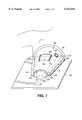
- FIG. 1shows a perspective view of a breast stabilization device in use, according to an embodiment of the present invention.
- FIG. 2shows a perspective view of the underside of a breast stabilization device, according to an embodiment of the present invention.
- FIG. 3is a cross-section of a breast stabilization device according to an embodiment of the present invention shown in FIG. 1, taken along line AA'.
- FIG. 4is a side view of the breast stabilization device in use, according to an embodiment of the present invention, showing an interventional device inserted in the breast tissue.
- FIG. 5is a flow chart of a method of biopsying and/or excising a breast lesion according to an embodiment of the present invention.
- FIG. 1shows an embodiment of the breast stabilization device according to an embodiment of the present invention.
- the breast stabilization device 100 shown in FIG. 1is depicted in use, and secured to a flat surface 195.
- the flat surface 195is shown for ease of description only and forms no part of the present invention.
- the flat surface 195may be a lower compression plate of a mammography imaging device (not shown).
- the breast stabilization device 100has a shape that conforms to the superior and lateral sides of a female breast 105. This shape may, in general terms, be characterized as a truncated semi-conical shape, although the device's size and shape, according to the present invention, may be adapted to fit various breast sizes and shapes.
- the breast stabilization device 100generally conforms to the size and shape of a female breast 105 as the breast 105 rests on a flat surface 195, such as a lower compression plate 195 of a mammography machine. Therefore, most of the inferior portion of the breast 105 shown in FIG. 1 lies substantially flat against the surface 195.
- the superior portion of the breastmay be thought of that portion of the breast that is above a plane through the nipple and perpendicular to the chest wall and the inferior portion of the breast may be thought of that portion of the breast that lies below that plane, when the woman is in an upright position.
- the superior portion of the breastmay be thought of as that portion of the breast that does not rest on the flat surface 195, irrespective of the position of the woman.
- the breast stabilization device 100covers substantially the entire superior portion of the breast 105 as the breast 105 rests against the flat surface 100 and may cover some of the inferior portion thereof
- the breast stabilization device 100includes a proximal end 110 and a distal end 115.
- the distal end 115is disposed, in use, closest to the nipple-areolar complex 126 whereas the proximal end 110 of the breast stabilization device 100 is disposed, in use, closest to the patient's chest 112.
- the distal end of the device 100is truncated, and includes an opening 130 that is configured to allow, in use, at least a portion of the nipple-areolar complex to protrude therethrough.
- the nipple 122 and the areola 124protrude from the opening 130 of the breast stabilizing device 100 according to the present invention.
- the opening 130may allow a portion of the breast 105 that is adjacent the peri-areolar border 125 to be exposed therethrough.
- the breast stabilization device 100 shown in FIG. 1may also include a first flange 135 and a second flange 140.
- the first and second flanges 135, 140may be disposed on either side of the breast stabilization device 100 and may extend parallel to the flat surface 195.
- the flanges 135 and 140secure the breast stabilization device 100 to the flat surface 195.
- the first and second flanges 135, 140may include an adhesive layer on the side thereof facing (in use) the flat surface 195.
- the first and second flanges 135, 140may be clamped to the flat surface 195 by any conventional clamping tool.
- both an adhesive layer on the side of the flanges 135, 140 facing the flat surface 195 and clamping tool(s)may be employed to secure the breast stabilization device 100 to the flat surface 195.
- the flanges 135, 140may extend all or a portion of the distance from the proximal end 110 of the device 100 to the distal end 115 thereof.
- the flanges 135, 140may be continuous as shown in FIG. 1, or may be composed of a plurality of discrete elements facing the flat surface 195.
- the breast stabilization device 100may also include a third flange 145.
- the third flange 145may be disposed at or near the proximate end 110 of the breast stabilization device 100 and may secure the device 100 to the patient's chest wall 112.
- the side of the third flange 145 facing the patient's chest wallincludes an adhesive layer to seal device 100 against the skin of the patient's chest.
- the first and second flanges 135, 140may include relatively stiff material, such as a relatively hard plastic material for example, the third flange 145 may be relatively softer and include a relatively soft plastic material. In this manner, a good and substantially fluid (e.g., air)-tight seal may be formed between the proximal end 110 of the device 100 and the patient's chest wall 112.
- the breast stabilizing device 100may include one or more windows 150 (one such window 150 being shown in FIG. 1) exposing the breast 105 therethrough.
- the window or windows 150may include one or more lips 155.
- the lip or lips 155may serve as a platform on which to attach or clamp, for example, instruments such as imaging devices and the like. Indeed, surface ultrasound may be carried out through the window or windows 150 during an imaging and/or interventional procedure and the surface ultrasound device (not shown) may be secured to the lip or lips 155 of the window or windows 150.
- the lip or lips 155may be integral to the window or windows 160 or may be removable therefrom. If removable, the lip or lips 155 may be friction-fitted to the shell of the breast stabilization device 100, in the manner discussed in detail with reference to FIG. 3 below.
- a suction port or ports 160may also be disposed within the breast stabilization device 100.
- a syringe or other vacuum-inducing devicemay be attached, clamped or otherwise removably affixed to the suction port or ports 160 to create a partial vacuum within the breast stabilization device 100, in the manner disclosed relative to FIG. 2.
- FIG. 2shows the breast stabilization device 100 in an orientation wherein the underside 230 of the device 100 is visible, the underside being that side of the device 100 that comes into contact with the patient's skin (breast) during use.
- a layer of adhesive 210may be disposed on each of the first, second and third flanges 135, 140 and 145, respectively.
- the adhesive 210 disposed on the third flange 145may be different than the adhesive 210 disposed on the flanges 135 and 140, as the adhesive 210 disposed on the third flange 145 contacts the patient's skin.
- a smooth sealing surface 220may surround the window or windows 150.
- the sealing surface 220facilitates the maintenance of a good seal between the breast 105 (not shown in FIG. 2) and the breast stabilization device 100.
- a similar sealing surface 225may surround the opening 130, again to facilitate the maintenance of a seal between the patient's breast and the stabilization device 100.
- An adhesive layer 210may be disposed on the sealing surfaces 220, 225.
- the underside 230 of the stabilization devicemay include a plurality of through holes 240.
- the through holes 240are in fluid communication with the suction port 160 shown in FIG. 1.
- fluidair, for example
- the breast 105is drawn toward the underside 230 of the device 100, thereby somewhat expanding the breast 105 between the flat surface 195 and the underside 230 of the breast stabilization device 100.
- an adhesive layer 235may be disposed on the underside 230 of the breast stabilization device 100.
- the surgeonmay peel a protective plastic film (not shown) from the underside 230 of the device 100, thereby exposing the adhesive 235 in preparation of the placement of the device 100 on the patient's breast 105.
- FIG. 3shows a cross-sectional view of an embodiment of the present invention, taken along line AA' of FIG. 1.
- the breast stabilization device 100may include an outer member 310 and an inner member 320.
- the outer member 310 and the inner member 320may include a plastic material and may be joined to one another by an adhesive or by other means.
- the outer member 310may be fabricated of a relatively stiff material and the inner member 320 may be of a relatively softer material, to better conform to the patient's breast 105 (shown in FIG. 1).
- the outer member 310 and the inner member 320may be formed and joined to one another so as to create an interstitial space 315 therebetween.
- the inner member 320may include a plurality of through holes 240 (FIG.
- the stabilization device 100may be drawn from the suction port 160, thereby causing the breast 105 to be drawn toward the underside 230 of the stabilization device 100. This, in turn, may cause the breast 105 to expand somewhat within the device 100.
- the lip or lips 155may be integral at least to the outer member 310 or may be removable and friction-fitted thereto, for example.
- FIG. 4shows an embodiment of the present invention in use, during an imaging and interventional (e.g., biopsy or excisional) procedure.
- FIG. 4is a side view (not to scale) of the stabilization device 100 disposed on a breast 105.
- the stabilization device 100may be secured to a flat surface 195, such as a lower compression plate of a mammography device.
- the stabilization device 100 shown in FIG. 4may also be secured to the patient's chest wall 112 by means of a preferably adhesive third flange 145.
- An imaging and/or interventional device 415(not shown to scale in FIG. 4) is shown inserted into the breast 105.
- the device 415is shown inserted through an incision 450 made in the peri-areolar border 125.
- the portion of the device 415 that is inserted in the breast 105is shown in dashed lines.
- the device 415is inserted through the opening 130 of the device 100, in the incision 450 in the breast 105 and guided adjacent to a lesion 410, such as a group of suspicious cells, microcalcifications, necrotic cells or cancer.
- the imaging and/or interventional device 415is preferably equipped with an ultrasound transducer 420. Once the device 415 is correctly positioned near the lesion 410, the ultrasound transducer 420 may be activated to generate information regarding the structure of the breast 105 from within the breast tissue itself The frequency of the ultrasound transducer 420 may be selected within the range of about 7.5 MHz to about 20 MHz.
- the information generated by the ultrasound transducer 420may be relayed via a communication link 440 (wired or wireless) to a display and/or data processing device 445, preferably located within the view of the operator of the device 415.
- the device 415constitutes an intra-tissue ultrasonic device that penetrates directly into breast tissue to image structure therein.
- a suitable imaging/interventional device 415is described in commonly assigned United States patent application Ser. No. 09/146,743, entitled “Excisional Biopsy Devices And Methods", filed on Sep. 3, 1998, the disclosure of which is hereby incorporated by reference in its entirety.
- the device 415may also be equipped with a cutting tool 430 which may utilize a sharpened edge and/or RF energy to cut and/or cauterize the breast tissue.
- a cutting tool 430which may utilize a sharpened edge and/or RF energy to cut and/or cauterize the breast tissue.
- the intra-tissue ultrasound transducer 420allows real time imaging of the lesion 410 within the breast 105 as the device 415 is deployed within the breast adjacent the lesion 410. This real time imaging allows a precise deployment of the cutting tool 430 to only cut that which is strictly necessary to obtain the necessary tissue sample and/or to excise the lesion in toto.
- the intra-tissue ultrasound transducermay also be advantageously utilized to insure that adequate margins of healthy tissue are present around the excised lesion 410, both to reduce the probability of seeding the retraction path of the device 415 with potentially cancerous cells and to allow a proper histopathological examination of the entire lesion 410.
- FIG. 5is a flowchart of a method of biopsying and/or excising a breast lesion according to an embodiment of the present invention.
- the methodbegins at step SO.
- the breastis compressed, e.g., between a first flat surface and a second flat surface.
- the first flat surfacemay include an upper compression plate of a mammography device and the second flat surface may include a lower compression plate thereof
- step S2at least two stereo mammography views are taken of the compressed breast.
- Step S3calls for the computation, from the stereo views, of the spatial coordinates (for example, x, y, z rectangular coordinates) of the target lesion within the breast, such as is shown at reference numeral 410 in FIG. 4.
- the spatial coordinatesfor example, x, y, z rectangular coordinates
- Steps S2 and S3are optional, as indicated by the dashed lines, it being possible to use standard mammography localization techniques.
- step S4the spatial coordinates computed in S3 are re-calculated, so that the coordinates indicate the position of the lesion within the breast relative to the superior peri-areolar border of the breast, as shown at 450 in FIG. 4.
- step S5the area (e.g., the nipple-areolar complex 126 shown in FIG. 1) is surgically prepped with, for example, Betadine. Local anaesthetic is infused in the breast in step S6 and an incision is made at or near the peri-areolar border, as shown at 450 in FIG. 4.
- an imaging and/or interventional devicesuch as shown at 415 in FIG. 4, is inserted through the incision made in step S7 and the device is advanced through the breast to a position adjacent the target lesion in the compressed breast.
- Step S8is preferably carried out under stereotactic guidance to the re-calculated spatial coordinates obtained in step S4.
- the position of the imaging/interventional devicemay be confirmed using mammography.
- the ultrasound transducer of the imaging/interventional deviceis energized.
- An embodiment of a suitable imaging/interventional deviceis shown at reference 420 in FIG. 4. Using at least such intra-tissue ultrasound, the lesion is identified and localized and the imaging/interventional device is precisely positioned relative to the lesion within the compressed breast.
- Steps S11 through S16are carried out on an uncompressed breast.
- the breastis decompressed.
- the upper compression plate of the mammography devicemay be moved and/or removed, thus allowing the breast to decompress.
- the breast stabilization device according to the present inventionsuch as shown at 100 in FIG. 1, is fitted over the breast, while the breast rests on the second flat surface, such as the lower compression plate of the mammography device.
- the stabilization deviceis then secured to the second flat surface and/or to the patient's chest wall. It is important that the patient remain substantially immobile during and after step SI I as the breast is decompressed.
- step SI 3suction is applied to the stabilization device according to the present invention through, for example, the suction port 160 shown in FIGS. 1, 3 and 4.
- Thiscauses fluid (air, for example) to be drawn through the plurality of through holes 240 of FIG. 2, through the interstitial space 315 between the outer member 310 and the inner member 320 of FIG. 3 and through the suction port 160.
- Thisdraws the breast 105 in intimate contact with the underside 230 of the stabilization device 230, slightly expanding the breast volume and stabilizing the breast 105 within the device 100.
- step S14additional anaesthetic is infused within the breast as needed.
- the cutting toolsuch as the cutting tool shown at 430 in FIG. 4 is deployed and the lesion is biopsied and/or excised under the guidance of the preferably real time intra-tissue images of the breast generated by the imaging/interventional device ultrasound transducer.
- the cutting toolmay be deployed under both intra-tissue ultrasound as described above and under surface ultrasound, from the window or windows 150 shown in FIGS. 1-4.
- the tissue sample or lesionmay then be biopsied or excised and retrieved from the imaging/interventional device, the device retracted and the incision closed.
- the methodends at step S16.
Landscapes
- Health & Medical Sciences (AREA)
- Life Sciences & Earth Sciences (AREA)
- Medical Informatics (AREA)
- Engineering & Computer Science (AREA)
- Surgery (AREA)
- Heart & Thoracic Surgery (AREA)
- General Health & Medical Sciences (AREA)
- Nuclear Medicine, Radiotherapy & Molecular Imaging (AREA)
- Veterinary Medicine (AREA)
- Pathology (AREA)
- Public Health (AREA)
- Biomedical Technology (AREA)
- Animal Behavior & Ethology (AREA)
- Molecular Biology (AREA)
- Biophysics (AREA)
- Physics & Mathematics (AREA)
- High Energy & Nuclear Physics (AREA)
- Radiology & Medical Imaging (AREA)
- Optics & Photonics (AREA)
- Oral & Maxillofacial Surgery (AREA)
- Dentistry (AREA)
- Neurosurgery (AREA)
- Ultra Sonic Daignosis Equipment (AREA)
- Apparatus For Radiation Diagnosis (AREA)
- Surgical Instruments (AREA)
- Closed-Circuit Television Systems (AREA)
Abstract
Description
Claims (22)
Priority Applications (8)
| Application Number | Priority Date | Filing Date | Title |
|---|---|---|---|
| US09/200,661US6122542A (en) | 1998-11-25 | 1998-11-25 | Breast stabilization devices and imaging and interventional methods using the same |
| CA002473138ACA2473138A1 (en) | 1998-11-25 | 1999-11-12 | Breast stabilization devices and imaging and interventional methods using same |
| CA002289423ACA2289423C (en) | 1998-11-25 | 1999-11-12 | Breast stabilization devices and imaging and interventional methods using same |
| EP99309139AEP1004274A1 (en) | 1998-11-25 | 1999-11-17 | Breast stabilization devices and imaging and interventional methods using same |
| NZ501155ANZ501155A (en) | 1998-11-25 | 1999-11-18 | Breast stabilization device with shape to correspond to upper half of breast, and typically with inner flexible member actuated by suction to contact breast |
| JP33353099AJP3545294B2 (en) | 1998-11-25 | 1999-11-24 | Breast stabilization device |
| AU60624/99AAU756569C (en) | 1998-11-25 | 1999-11-25 | Breast stabilization devices and imaging and interventional methods using same |
| US09/588,033US6304770B1 (en) | 1998-11-25 | 2000-06-05 | Breast stabilization devices and imaging and interventional methods using same |
Applications Claiming Priority (1)
| Application Number | Priority Date | Filing Date | Title |
|---|---|---|---|
| US09/200,661US6122542A (en) | 1998-11-25 | 1998-11-25 | Breast stabilization devices and imaging and interventional methods using the same |
Related Child Applications (1)
| Application Number | Title | Priority Date | Filing Date |
|---|---|---|---|
| US09/588,033DivisionUS6304770B1 (en) | 1998-11-25 | 2000-06-05 | Breast stabilization devices and imaging and interventional methods using same |
Publications (1)
| Publication Number | Publication Date |
|---|---|
| US6122542Atrue US6122542A (en) | 2000-09-19 |
Family
ID=22742636
Family Applications (2)
| Application Number | Title | Priority Date | Filing Date |
|---|---|---|---|
| US09/200,661Expired - LifetimeUS6122542A (en) | 1998-11-25 | 1998-11-25 | Breast stabilization devices and imaging and interventional methods using the same |
| US09/588,033Expired - Fee RelatedUS6304770B1 (en) | 1998-11-25 | 2000-06-05 | Breast stabilization devices and imaging and interventional methods using same |
Family Applications After (1)
| Application Number | Title | Priority Date | Filing Date |
|---|---|---|---|
| US09/588,033Expired - Fee RelatedUS6304770B1 (en) | 1998-11-25 | 2000-06-05 | Breast stabilization devices and imaging and interventional methods using same |
Country Status (5)
| Country | Link |
|---|---|
| US (2) | US6122542A (en) |
| EP (1) | EP1004274A1 (en) |
| JP (1) | JP3545294B2 (en) |
| CA (1) | CA2289423C (en) |
| NZ (1) | NZ501155A (en) |
Cited By (30)
| Publication number | Priority date | Publication date | Assignee | Title |
|---|---|---|---|---|
| US6507748B2 (en)* | 1999-12-30 | 2003-01-14 | The Brigham And Women's Hospital, Inc. | Compression apparatus for diagnostically examining breast tissue |
| US6511433B1 (en)* | 2001-07-30 | 2003-01-28 | The United States Of America As Represented By The Secretary Of The Navy | Active acoustic array for ultrasonic biomedical applications |
| US20030069501A1 (en)* | 2001-04-06 | 2003-04-10 | Marmarelis Vasilis Z. | High-resolution 3D ultrasonic transmission imaging |
| US6679850B1 (en) | 2002-08-30 | 2004-01-20 | Henry T. Uhrig | Breast stabilizer |
| US20040064046A1 (en)* | 2002-06-28 | 2004-04-01 | Alfred E. Mann Institute For Biomedical Engineering | Scanning devices for three-dimensional ultrasound mammography |
| US20040087851A1 (en)* | 2002-10-31 | 2004-05-06 | Manoa Medical, Inc. A Delaware Corporation | Soft tissue orientation and imaging guide systems and methods |
| US20060050844A1 (en)* | 2003-12-30 | 2006-03-09 | Galkin Benjamin M | Mammography cushioning devices and methods |
| US20060074287A1 (en)* | 2004-09-30 | 2006-04-06 | General Electric Company | Systems, methods and apparatus for dual mammography image detection |
| US20070270635A1 (en)* | 2004-06-07 | 2007-11-22 | James Schellenberg | System and Micro-Catheter Devices for Medical Imaging of the Breast |
| US20080037703A1 (en)* | 2006-08-09 | 2008-02-14 | Digimd Corporation | Three dimensional breast imaging |
| US20080091105A1 (en)* | 2006-09-28 | 2008-04-17 | Sheldon Weinbaum | System and method for in vivo imaging of blood vessel walls to detect microcalcifications |
| US7512211B2 (en) | 2003-12-30 | 2009-03-31 | Galkin Benjamin M | Mammography systems and methods, including methods for improving the sensitivity and specificity of the computer-assisted detection (CAD) process |
| US20100049093A1 (en)* | 2003-12-30 | 2010-02-25 | Galkin Benjamin M | Acoustic monitoring of a breast and sound databases for improved detection of breast cancer |
| US20100177866A1 (en)* | 2005-04-01 | 2010-07-15 | Keizi Shibuya | Mammography Equipment |
| WO2014074602A1 (en)* | 2012-11-08 | 2014-05-15 | The Regents Of The University Of California | Breast support and immobilization device for radiotherapy |
| US8848865B2 (en) | 2011-04-27 | 2014-09-30 | Fujifilm Corporation | Radiographic image capturing apparatus |
| US20150230868A1 (en)* | 2014-02-18 | 2015-08-20 | JJ Dogs LLC | Needle Guide For Percutaneous Lung Biopsy |
| US20180125437A1 (en)* | 2011-11-18 | 2018-05-10 | Hologic Inc. | X-ray mammography and/or breast tomosynthesis using a compression paddle |
| WO2018093124A3 (en)* | 2016-11-16 | 2018-08-09 | 재단법인 아산사회복지재단 | Customized surgical guide and customized surgical guide generating method and generating program |
| US20180325654A1 (en)* | 2009-04-29 | 2018-11-15 | Keller Medical, Inc. | Silicone breast implant delivery |
| WO2019200299A1 (en)* | 2018-04-12 | 2019-10-17 | Howard University | Surgical instrument stabilization device |
| US20210137557A1 (en)* | 2019-05-13 | 2021-05-13 | Stephen David BRESNICK | Biofilm protection implant shield |
| CN113317811A (en)* | 2021-05-31 | 2021-08-31 | 中国人民解放军空军军医大学 | Mammary gland molybdenum target photography pendulum position auxiliary device |
| US11291371B2 (en)* | 2019-07-16 | 2022-04-05 | Sergio Lara Pereira Monteiro | Method and means to make infrared image of the female breast, other human organs and other objects |
| US11826197B2 (en) | 2021-05-13 | 2023-11-28 | General Electric Company | Patient-specific neuromodulation alignment structures |
| US11963860B2 (en) | 2019-12-10 | 2024-04-23 | Stephen David BRESNICK | Implant delivery device with biofilm protection shield |
| US12059278B2 (en) | 2011-11-18 | 2024-08-13 | Hologic, Inc. | X-ray mammography and/or breast tomosynthesis using a compression paddle with an inflatable jacket enhancing imaging and improving patient comfort |
| US12201467B2 (en) | 2017-08-16 | 2025-01-21 | Hologic, Inc. | Motion, compression, and positioning corrections in medical imaging |
| US12295759B2 (en) | 2020-01-24 | 2025-05-13 | Hologic, Inc. | Horizontally-displaceable foam breast compression paddle |
| US12295760B2 (en) | 2017-08-11 | 2025-05-13 | Hologic, Inc. | Breast compression paddle with access corners |
Families Citing this family (32)
| Publication number | Priority date | Publication date | Assignee | Title |
|---|---|---|---|---|
| JP4652605B2 (en)* | 2001-04-05 | 2011-03-16 | ジーイー・メディカル・システムズ・グローバル・テクノロジー・カンパニー・エルエルシー | Shooting aid |
| SE0201806D0 (en)* | 2002-06-13 | 2002-06-13 | Siemens Elema Ab | X-ray diagnostic apparatus for mammography examinations |
| US20040068180A1 (en)* | 2002-10-04 | 2004-04-08 | Jeffrey Collins | Rotary ultrasound scanner for soft tissue examination |
| US7828744B2 (en)* | 2003-04-23 | 2010-11-09 | Boston Scientific Scimed, Inc. | Method and assembly for breast immobilization |
| CN1933787A (en)* | 2004-01-23 | 2007-03-21 | 特拉克斯医疗有限公司 | Methods and apparatus for performing procedures on target locations in the body |
| EP1727472B1 (en)* | 2004-03-16 | 2010-11-17 | Helix Medical Systems Ltd. | Circular ultrasound tomography scanner and method |
| US7699783B2 (en)* | 2004-04-08 | 2010-04-20 | Techniscan, Inc. | Method for imaging and treating a breast |
| EP1800316A4 (en)* | 2004-09-15 | 2009-03-18 | Scient Biospy Ltd | Breast cancer detection and biopsy |
| US20080004526A1 (en)* | 2004-09-15 | 2008-01-03 | Scientific Biopsy Ltd. | Breast Cancer Detection and Biopsy |
| JP4801922B2 (en)* | 2005-03-31 | 2011-10-26 | 株式会社東芝 | Mammography treatment device |
| US11020086B2 (en)* | 2005-09-01 | 2021-06-01 | Shih-Ping Wang | Breast ultrasound scanning |
| US20070055159A1 (en)* | 2005-09-01 | 2007-03-08 | Shih-Ping Wang | Breast ultrasound scanning template |
| US7742796B2 (en)* | 2005-10-25 | 2010-06-22 | General Electric Company | Breast immobilization device and method of imaging the breast |
| US20070232953A1 (en)* | 2006-03-31 | 2007-10-04 | Ethicon Endo-Surgery, Inc. | MRI biopsy device |
| JP2007289326A (en)* | 2006-04-24 | 2007-11-08 | Toshiba Corp | X-ray CT apparatus and breast fixture |
| EP1961385A1 (en)* | 2007-02-21 | 2008-08-27 | European Organisation for Nuclear Research CERN | Combined nuclear and sonographic imaging apparatus and method |
| JP5481038B2 (en)* | 2007-04-05 | 2014-04-23 | 株式会社東芝 | Ultrasound diagnostic apparatus, breast imaging system, and breast imaging program |
| WO2008143901A2 (en)* | 2007-05-15 | 2008-11-27 | Techniscan, Inc. | Improved imaging system |
| US8652022B2 (en)* | 2007-09-10 | 2014-02-18 | Boston Scientific Scimed, Inc. | Stabilizer and method for irradiating tumors |
| DE102008009967A1 (en)* | 2008-02-20 | 2009-09-17 | Siemens Aktiengesellschaft | Mammography system and method for sonographic and radiographic examination of a breast |
| DE102008055737A1 (en)* | 2008-11-04 | 2010-05-06 | Siemens Aktiengesellschaft | Tomosynthesegerät |
| EP2570083A1 (en) | 2011-09-16 | 2013-03-20 | Theraclion | Medical support for a body part |
| JP6057323B2 (en)* | 2012-10-17 | 2017-01-11 | 学校法人 愛知医科大学 | Vascular compression device used for embolic sclerotherapy of vascular malformation |
| KR101405747B1 (en)* | 2012-11-06 | 2014-06-27 | 연세대학교 원주산학협력단 | A pneumatic curved compression paddle for digital breast Tomosynthesis system with stationary detector |
| CN113768529A (en)* | 2013-04-26 | 2021-12-10 | 蒂莫西·R·斯坦戈 | X-ray breast imaging system and compression paddle for X-ray breast imaging system |
| JP5785214B2 (en) | 2013-05-08 | 2015-09-24 | 富士フイルム株式会社 | Mold, surgical support set, surgical support device, surgical support method, and surgical support program |
| EP2977022A1 (en)* | 2014-07-25 | 2016-01-27 | Fujifilm Corporation | Pattern and surgery support set, apparatus, method and program |
| WO2017091787A1 (en)* | 2015-11-25 | 2017-06-01 | The Regents Of The University Of California | 3d-beam modulation filter for equalizing dose and image quality in breast ct |
| JP2017221299A (en)* | 2016-06-14 | 2017-12-21 | キヤノン株式会社 | Radiographic imaging device, radiographic imaging system, radiographic imaging method and program |
| US11123032B2 (en) | 2017-12-05 | 2021-09-21 | Wolfram R. JARISCH | Wide area single or dual guided breast tissue tomography and tomosynthesis imaging systems and methods |
| CA3098900A1 (en)* | 2018-04-30 | 2019-11-07 | Memorial Sloan Kettering Cancer Center | Compression paddles for breast biopsies |
| ES2923501T3 (en)* | 2018-05-15 | 2022-09-28 | Cairnsurgical Inc | Devices to guide tissue treatment and/or tissue removal procedures |
Citations (31)
| Publication number | Priority date | Publication date | Assignee | Title |
|---|---|---|---|---|
| US3971950A (en)* | 1975-04-14 | 1976-07-27 | Xerox Corporation | Independent compression and positioning device for use in mammography |
| DE2610111A1 (en)* | 1976-03-11 | 1977-09-15 | Friedrich Guenter Schwarz | Body holder for X:ray examination - has housing permeable to X:rays over part of body and connected to fluid source |
| US4434799A (en)* | 1982-03-02 | 1984-03-06 | Siemens Ag | Ultrasound apparatus for medical examinations |
| US4509368A (en)* | 1981-06-22 | 1985-04-09 | The Commonwealth Of Australia | Ultrasound tomography |
| US4563768A (en)* | 1983-07-11 | 1986-01-07 | University Of Virginia Alumni Patents Foundations | Mamographic device using localized compression cone |
| US4691333A (en)* | 1985-12-27 | 1987-09-01 | Gabriele Joseph M | Breast compression and needle localization apparatus |
| US4829184A (en)* | 1984-06-25 | 1989-05-09 | Nelson Robert S | Reflective, transmissive high resolution imaging apparatus |
| US5009660A (en)* | 1989-09-15 | 1991-04-23 | Visx, Incorporated | Gas purging, eye fixation hand piece |
| US5056523A (en)* | 1989-11-22 | 1991-10-15 | Board Of Regents, The University Of Texas System | Precision breast lesion localizer |
| US5171321A (en)* | 1992-03-09 | 1992-12-15 | Davis Joseph P | Nipple prosthesis and method of making the same |
| US5308321A (en)* | 1992-05-05 | 1994-05-03 | Castro Donna J | Retainer assisted by vacuum expansion system |
| US5386447A (en)* | 1992-09-23 | 1995-01-31 | Fischer Imaging Corporation | Mammographic screening and biopsy apparatus |
| US5409497A (en)* | 1991-03-11 | 1995-04-25 | Fischer Imaging Corporation | Orbital aiming device for mammo biopsy |
| US5451789A (en)* | 1993-07-19 | 1995-09-19 | Board Of Regents, The University Of Texas System | High performance positron camera |
| US5590166A (en)* | 1995-12-28 | 1996-12-31 | Instrumentarium Corporation | Mammography unit |
| US5590655A (en)* | 1993-09-20 | 1997-01-07 | Hussman; Karl L. | Frameless laser guided stereotactic localization system |
| US5660185A (en)* | 1995-04-13 | 1997-08-26 | Neovision Corporation | Image-guided biopsy apparatus with enhanced imaging and methods |
| US5662109A (en)* | 1990-12-14 | 1997-09-02 | Hutson; William H. | Method and system for multi-dimensional imaging and analysis for early detection of diseased tissue |
| US5702405A (en)* | 1994-11-30 | 1997-12-30 | Siemens Aktiengesellschaft | Stereotactic auxiliary attachment for a tomography apparatus for tomogram guided implementation of a biopsy |
| US5706327A (en)* | 1996-02-09 | 1998-01-06 | Trex Medical Corporation | Method and apparatus for mammographic compression |
| US5776177A (en)* | 1992-12-21 | 1998-07-07 | Macwhinnie; Virginia | C-shaped heat pack for thermal treatment of breast |
| US5805665A (en)* | 1995-06-05 | 1998-09-08 | Nelson; Robert S. | Anthropomorphic mammography phantoms |
| US5810742A (en)* | 1994-10-24 | 1998-09-22 | Transcan Research & Development Co., Ltd. | Tissue characterization based on impedance images and on impedance measurements |
| US5820552A (en)* | 1996-07-12 | 1998-10-13 | United States Surgical Corporation | Sonography and biopsy apparatus |
| US5855554A (en)* | 1997-03-17 | 1999-01-05 | General Electric Company | Image guided breast lesion localization device |
| US5860934A (en)* | 1992-12-21 | 1999-01-19 | Artann Corporation | Method and device for mechanical imaging of breast |
| US5868673A (en)* | 1995-03-28 | 1999-02-09 | Sonometrics Corporation | System for carrying out surgery, biopsy and ablation of a tumor or other physical anomaly |
| WO1999008647A1 (en)* | 1997-08-13 | 1999-02-25 | Daniel Kaiser | Method and apparatus for tissue enlargement |
| US5876339A (en)* | 1997-01-09 | 1999-03-02 | Lemire; Robert | Apparatus for optical breast imaging |
| US5899865A (en)* | 1988-12-21 | 1999-05-04 | Non-Invasive Technology, Inc. | Localization of abnormal breast tissue using time-resolved spectroscopy |
| US5999836A (en)* | 1995-06-06 | 1999-12-07 | Nelson; Robert S. | Enhanced high resolution breast imaging device and method utilizing non-ionizing radiation of narrow spectral bandwidth |
Family Cites Families (7)
| Publication number | Priority date | Publication date | Assignee | Title |
|---|---|---|---|---|
| US5526822A (en)* | 1994-03-24 | 1996-06-18 | Biopsys Medical, Inc. | Method and apparatus for automated biopsy and collection of soft tissue |
| US5954670A (en)* | 1994-10-05 | 1999-09-21 | Baker; Gary H. | Mandrel-guided tandem multiple channel biopsy guide device and method of use |
| US5499989A (en) | 1994-12-22 | 1996-03-19 | Labash; Stephen S. | Breast biopsy apparatus and method of use |
| US5782771A (en)* | 1995-04-17 | 1998-07-21 | Hussman; Karl L. | Dual, fused, and grooved optical localization fibers |
| US5980941A (en) | 1997-08-20 | 1999-11-09 | Fuisz Technologies Ltd. | Self-binding shearform compositions |
| US6015390A (en)* | 1998-06-12 | 2000-01-18 | D. Krag Llc | System and method for stabilizing and removing tissue |
| US6022362A (en)* | 1998-09-03 | 2000-02-08 | Rubicor Medical, Inc. | Excisional biopsy devices and methods |
- 1998
- 1998-11-25USUS09/200,661patent/US6122542A/ennot_activeExpired - Lifetime
- 1999
- 1999-11-12CACA002289423Apatent/CA2289423C/ennot_activeExpired - Fee Related
- 1999-11-17EPEP99309139Apatent/EP1004274A1/ennot_activeWithdrawn
- 1999-11-18NZNZ501155Apatent/NZ501155A/enunknown
- 1999-11-24JPJP33353099Apatent/JP3545294B2/ennot_activeExpired - Fee Related
- 2000
- 2000-06-05USUS09/588,033patent/US6304770B1/ennot_activeExpired - Fee Related
Patent Citations (31)
| Publication number | Priority date | Publication date | Assignee | Title |
|---|---|---|---|---|
| US3971950A (en)* | 1975-04-14 | 1976-07-27 | Xerox Corporation | Independent compression and positioning device for use in mammography |
| DE2610111A1 (en)* | 1976-03-11 | 1977-09-15 | Friedrich Guenter Schwarz | Body holder for X:ray examination - has housing permeable to X:rays over part of body and connected to fluid source |
| US4509368A (en)* | 1981-06-22 | 1985-04-09 | The Commonwealth Of Australia | Ultrasound tomography |
| US4434799A (en)* | 1982-03-02 | 1984-03-06 | Siemens Ag | Ultrasound apparatus for medical examinations |
| US4563768A (en)* | 1983-07-11 | 1986-01-07 | University Of Virginia Alumni Patents Foundations | Mamographic device using localized compression cone |
| US4829184A (en)* | 1984-06-25 | 1989-05-09 | Nelson Robert S | Reflective, transmissive high resolution imaging apparatus |
| US4691333A (en)* | 1985-12-27 | 1987-09-01 | Gabriele Joseph M | Breast compression and needle localization apparatus |
| US5899865A (en)* | 1988-12-21 | 1999-05-04 | Non-Invasive Technology, Inc. | Localization of abnormal breast tissue using time-resolved spectroscopy |
| US5009660A (en)* | 1989-09-15 | 1991-04-23 | Visx, Incorporated | Gas purging, eye fixation hand piece |
| US5056523A (en)* | 1989-11-22 | 1991-10-15 | Board Of Regents, The University Of Texas System | Precision breast lesion localizer |
| US5662109A (en)* | 1990-12-14 | 1997-09-02 | Hutson; William H. | Method and system for multi-dimensional imaging and analysis for early detection of diseased tissue |
| US5409497A (en)* | 1991-03-11 | 1995-04-25 | Fischer Imaging Corporation | Orbital aiming device for mammo biopsy |
| US5171321A (en)* | 1992-03-09 | 1992-12-15 | Davis Joseph P | Nipple prosthesis and method of making the same |
| US5308321A (en)* | 1992-05-05 | 1994-05-03 | Castro Donna J | Retainer assisted by vacuum expansion system |
| US5386447A (en)* | 1992-09-23 | 1995-01-31 | Fischer Imaging Corporation | Mammographic screening and biopsy apparatus |
| US5776177A (en)* | 1992-12-21 | 1998-07-07 | Macwhinnie; Virginia | C-shaped heat pack for thermal treatment of breast |
| US5860934A (en)* | 1992-12-21 | 1999-01-19 | Artann Corporation | Method and device for mechanical imaging of breast |
| US5451789A (en)* | 1993-07-19 | 1995-09-19 | Board Of Regents, The University Of Texas System | High performance positron camera |
| US5590655A (en)* | 1993-09-20 | 1997-01-07 | Hussman; Karl L. | Frameless laser guided stereotactic localization system |
| US5810742A (en)* | 1994-10-24 | 1998-09-22 | Transcan Research & Development Co., Ltd. | Tissue characterization based on impedance images and on impedance measurements |
| US5702405A (en)* | 1994-11-30 | 1997-12-30 | Siemens Aktiengesellschaft | Stereotactic auxiliary attachment for a tomography apparatus for tomogram guided implementation of a biopsy |
| US5868673A (en)* | 1995-03-28 | 1999-02-09 | Sonometrics Corporation | System for carrying out surgery, biopsy and ablation of a tumor or other physical anomaly |
| US5660185A (en)* | 1995-04-13 | 1997-08-26 | Neovision Corporation | Image-guided biopsy apparatus with enhanced imaging and methods |
| US5805665A (en)* | 1995-06-05 | 1998-09-08 | Nelson; Robert S. | Anthropomorphic mammography phantoms |
| US5999836A (en)* | 1995-06-06 | 1999-12-07 | Nelson; Robert S. | Enhanced high resolution breast imaging device and method utilizing non-ionizing radiation of narrow spectral bandwidth |
| US5590166A (en)* | 1995-12-28 | 1996-12-31 | Instrumentarium Corporation | Mammography unit |
| US5706327A (en)* | 1996-02-09 | 1998-01-06 | Trex Medical Corporation | Method and apparatus for mammographic compression |
| US5820552A (en)* | 1996-07-12 | 1998-10-13 | United States Surgical Corporation | Sonography and biopsy apparatus |
| US5876339A (en)* | 1997-01-09 | 1999-03-02 | Lemire; Robert | Apparatus for optical breast imaging |
| US5855554A (en)* | 1997-03-17 | 1999-01-05 | General Electric Company | Image guided breast lesion localization device |
| WO1999008647A1 (en)* | 1997-08-13 | 1999-02-25 | Daniel Kaiser | Method and apparatus for tissue enlargement |
Non-Patent Citations (2)
| Title |
|---|
| NeoVision Corporation: SONOPSY Ultrasound Guided Breast Biopsy: Document No. 10369, Revision 1, Oct. 1996.* |
| NeoVision Corporation: SONOPSY Ultrasound-Guided Breast Biopsy: Document No. 10369, Revision 1, Oct. 1996. |
Cited By (46)
| Publication number | Priority date | Publication date | Assignee | Title |
|---|---|---|---|---|
| US6507748B2 (en)* | 1999-12-30 | 2003-01-14 | The Brigham And Women's Hospital, Inc. | Compression apparatus for diagnostically examining breast tissue |
| US7094205B2 (en)* | 2001-04-06 | 2006-08-22 | Alfred E. Mann Institute For Biomedical Engineering At The University Of Southern California | High-resolution 3D ultrasonic transmission imaging |
| US20030069501A1 (en)* | 2001-04-06 | 2003-04-10 | Marmarelis Vasilis Z. | High-resolution 3D ultrasonic transmission imaging |
| US6511433B1 (en)* | 2001-07-30 | 2003-01-28 | The United States Of America As Represented By The Secretary Of The Navy | Active acoustic array for ultrasonic biomedical applications |
| US20040064046A1 (en)* | 2002-06-28 | 2004-04-01 | Alfred E. Mann Institute For Biomedical Engineering | Scanning devices for three-dimensional ultrasound mammography |
| US7264592B2 (en) | 2002-06-28 | 2007-09-04 | Alfred E. Mann Institute For Biomedical Engineering At The University Of Southern California | Scanning devices for three-dimensional ultrasound mammography |
| US6679850B1 (en) | 2002-08-30 | 2004-01-20 | Henry T. Uhrig | Breast stabilizer |
| US7149566B2 (en) | 2002-10-31 | 2006-12-12 | Manoa Medical, Inc. | Soft tissue orientation and imaging guide systems and methods |
| US20040087851A1 (en)* | 2002-10-31 | 2004-05-06 | Manoa Medical, Inc. A Delaware Corporation | Soft tissue orientation and imaging guide systems and methods |
| US20100049093A1 (en)* | 2003-12-30 | 2010-02-25 | Galkin Benjamin M | Acoustic monitoring of a breast and sound databases for improved detection of breast cancer |
| US8100839B2 (en) | 2003-12-30 | 2012-01-24 | Galkin Benjamin M | Acoustic monitoring of a breast and sound databases for improved detection of breast cancer |
| US7251309B2 (en) | 2003-12-30 | 2007-07-31 | Galkin Benjamin M | Mammography cushioning devices and methods |
| US20060050844A1 (en)* | 2003-12-30 | 2006-03-09 | Galkin Benjamin M | Mammography cushioning devices and methods |
| US7142631B2 (en)* | 2003-12-30 | 2006-11-28 | Galkin Benjamin M | Mammography cushioning devices and methods |
| US7512211B2 (en) | 2003-12-30 | 2009-03-31 | Galkin Benjamin M | Mammography systems and methods, including methods for improving the sensitivity and specificity of the computer-assisted detection (CAD) process |
| US8340741B2 (en)* | 2004-06-07 | 2012-12-25 | James Schellenberg | System and micro-catheter devices for medical imaging of the breast |
| US20070270635A1 (en)* | 2004-06-07 | 2007-11-22 | James Schellenberg | System and Micro-Catheter Devices for Medical Imaging of the Breast |
| US20060074287A1 (en)* | 2004-09-30 | 2006-04-06 | General Electric Company | Systems, methods and apparatus for dual mammography image detection |
| US20100177866A1 (en)* | 2005-04-01 | 2010-07-15 | Keizi Shibuya | Mammography Equipment |
| US20080037703A1 (en)* | 2006-08-09 | 2008-02-14 | Digimd Corporation | Three dimensional breast imaging |
| US20080091105A1 (en)* | 2006-09-28 | 2008-04-17 | Sheldon Weinbaum | System and method for in vivo imaging of blood vessel walls to detect microcalcifications |
| US8882674B2 (en)* | 2006-09-28 | 2014-11-11 | Research Foundation Of The City University Of New York | System and method for in vivo imaging of blood vessel walls to detect microcalcifications |
| US20180325654A1 (en)* | 2009-04-29 | 2018-11-15 | Keller Medical, Inc. | Silicone breast implant delivery |
| US8848865B2 (en) | 2011-04-27 | 2014-09-30 | Fujifilm Corporation | Radiographic image capturing apparatus |
| US12059278B2 (en) | 2011-11-18 | 2024-08-13 | Hologic, Inc. | X-ray mammography and/or breast tomosynthesis using a compression paddle with an inflatable jacket enhancing imaging and improving patient comfort |
| US20180125437A1 (en)* | 2011-11-18 | 2018-05-10 | Hologic Inc. | X-ray mammography and/or breast tomosynthesis using a compression paddle |
| US11950941B2 (en) | 2011-11-18 | 2024-04-09 | Hologic, Inc. | X-ray mammography and/or breast tomosynthesis using a compression paddle |
| US11259759B2 (en)* | 2011-11-18 | 2022-03-01 | Hologic Inc. | X-ray mammography and/or breast tomosynthesis using a compression paddle |
| US12310766B2 (en) | 2011-11-18 | 2025-05-27 | Hologic, Inc. | X-ray mammography and/or breast tomosynthesis using a compression paddle |
| US9913689B2 (en) | 2012-11-08 | 2018-03-13 | The Regents Of The University Of Califronia | Breast support and immobilization device for radiotherapy |
| WO2014074602A1 (en)* | 2012-11-08 | 2014-05-15 | The Regents Of The University Of California | Breast support and immobilization device for radiotherapy |
| US20150230868A1 (en)* | 2014-02-18 | 2015-08-20 | JJ Dogs LLC | Needle Guide For Percutaneous Lung Biopsy |
| US11154362B2 (en) | 2016-11-16 | 2021-10-26 | The Asan Foundation | Customized surgical guide and customized surgical guide generating method and generating program |
| WO2018093124A3 (en)* | 2016-11-16 | 2018-08-09 | 재단법인 아산사회복지재단 | Customized surgical guide and customized surgical guide generating method and generating program |
| US12295760B2 (en) | 2017-08-11 | 2025-05-13 | Hologic, Inc. | Breast compression paddle with access corners |
| US12201467B2 (en) | 2017-08-16 | 2025-01-21 | Hologic, Inc. | Motion, compression, and positioning corrections in medical imaging |
| WO2019200299A1 (en)* | 2018-04-12 | 2019-10-17 | Howard University | Surgical instrument stabilization device |
| US20210137557A1 (en)* | 2019-05-13 | 2021-05-13 | Stephen David BRESNICK | Biofilm protection implant shield |
| US11596441B2 (en)* | 2019-05-13 | 2023-03-07 | Stephen David BRESNICK | Biofilm protection implant shield |
| US12137938B2 (en) | 2019-05-13 | 2024-11-12 | Stephen David BRESNICK | Biofilm protection implant shield |
| US11291371B2 (en)* | 2019-07-16 | 2022-04-05 | Sergio Lara Pereira Monteiro | Method and means to make infrared image of the female breast, other human organs and other objects |
| US11963860B2 (en) | 2019-12-10 | 2024-04-23 | Stephen David BRESNICK | Implant delivery device with biofilm protection shield |
| US12295759B2 (en) | 2020-01-24 | 2025-05-13 | Hologic, Inc. | Horizontally-displaceable foam breast compression paddle |
| US11826197B2 (en) | 2021-05-13 | 2023-11-28 | General Electric Company | Patient-specific neuromodulation alignment structures |
| CN113317811B (en)* | 2021-05-31 | 2023-06-09 | 中国人民解放军空军军医大学 | Mammary gland molybdenum target photographic positioning auxiliary device |
| CN113317811A (en)* | 2021-05-31 | 2021-08-31 | 中国人民解放军空军军医大学 | Mammary gland molybdenum target photography pendulum position auxiliary device |
Also Published As
| Publication number | Publication date |
|---|---|
| CA2289423A1 (en) | 2000-05-25 |
| JP3545294B2 (en) | 2004-07-21 |
| NZ501155A (en) | 2001-09-28 |
| AU756569B2 (en) | 2003-01-16 |
| US6304770B1 (en) | 2001-10-16 |
| CA2289423C (en) | 2005-02-08 |
| EP1004274A1 (en) | 2000-05-31 |
| JP2000157554A (en) | 2000-06-13 |
| AU6062499A (en) | 2000-06-01 |
Similar Documents
| Publication | Publication Date | Title |
|---|---|---|
| US6122542A (en) | Breast stabilization devices and imaging and interventional methods using the same | |
| US6146377A (en) | Breast stabilization devices and methods | |
| JP3679368B2 (en) | Incisional biopsy device and method | |
| US6849080B2 (en) | Excisional biopsy device and methods | |
| US20040073106A1 (en) | Breast stabilizers having an open lattice structure and imaging methods using same | |
| JP2004033752A (en) | Magnetic resonance imaging compatible biopsy device having detachable probe | |
| AU2003203755B2 (en) | Breast Stabilization Devices and Imaging and Interventional Methods Using Same | |
| CA2473138A1 (en) | Breast stabilization devices and imaging and interventional methods using same | |
| AU2003200266B2 (en) | Method of Stabilising an Uncompressed Breast | |
| AU2003200267B2 (en) | Method of imaging a breast | |
| CA2413859C (en) | Excisional biopsy devices and methods | |
| HK1022824B (en) | Excisional biopsy device |
Legal Events
| Date | Code | Title | Description |
|---|---|---|---|
| AS | Assignment | Owner name:RUBICOR MEDICAL, INC., CALIFORNIA Free format text:ASSIGNMENT OF ASSIGNORS INTEREST;ASSIGNORS:LEE, ROBERTA;VETTER, JAMES W.;HYLAND, NATALIE N.;REEL/FRAME:009612/0948;SIGNING DATES FROM 19981120 TO 19981122 | |
| STCF | Information on status: patent grant | Free format text:PATENTED CASE | |
| FPAY | Fee payment | Year of fee payment:4 | |
| AS | Assignment | Owner name:DEMA, JOHN K., MARYLAND Free format text:INTELLECTUAL PROPERTY SECURITY AGREEMENT;ASSIGNOR:RUBICOR MEDICAL, INC.;REEL/FRAME:015653/0052 Effective date:20050106 | |
| AS | Assignment | Owner name:RUBICOR MEDICAL, INC., CALIFORNIA Free format text:RELEASE BY SECURED PARTY;ASSIGNOR:DEMA, JOHN K;REEL/FRAME:018711/0587 Effective date:20060824 | |
| FPAY | Fee payment | Year of fee payment:8 | |
| AS | Assignment | Owner name:COMERICA BANK, CALIFORNIA Free format text:SECURITY AGREEMENT;ASSIGNOR:RUBICOR MEDICAL, INC.;REEL/FRAME:020828/0811 Effective date:20080421 Owner name:OXFORD FINANCE CORPORATION, VIRGINIA Free format text:SECURITY AGREEMENT;ASSIGNOR:RUBICOR MEDICAL, INC.;REEL/FRAME:020828/0811 Effective date:20080421 Owner name:COMERICA BANK,CALIFORNIA Free format text:SECURITY AGREEMENT;ASSIGNOR:RUBICOR MEDICAL, INC.;REEL/FRAME:020828/0811 Effective date:20080421 Owner name:OXFORD FINANCE CORPORATION,VIRGINIA Free format text:SECURITY AGREEMENT;ASSIGNOR:RUBICOR MEDICAL, INC.;REEL/FRAME:020828/0811 Effective date:20080421 | |
| AS | Assignment | Owner name:HOLOGIC, INC., MASSACHUSETTS Free format text:SECURITY AGREEMENT;ASSIGNOR:RUBICOR MEDICAL, INC.;REEL/FRAME:020845/0034 Effective date:20080421 Owner name:HOLOGIC, INC.,MASSACHUSETTS Free format text:SECURITY AGREEMENT;ASSIGNOR:RUBICOR MEDICAL, INC.;REEL/FRAME:020845/0034 Effective date:20080421 | |
| AS | Assignment | Owner name:RUBICOR MEDICAL, LLC,CALIFORNIA Free format text:ASSIGNMENT OF ASSIGNORS INTEREST;ASSIGNOR:RM LIQUIDATING F/K/A RUBICOR MEDICAL, INC.;REEL/FRAME:024358/0197 Effective date:20100329 Owner name:RUBICOR MEDICAL, LLC, CALIFORNIA Free format text:ASSIGNMENT OF ASSIGNORS INTEREST;ASSIGNOR:RM LIQUIDATING F/K/A RUBICOR MEDICAL, INC.;REEL/FRAME:024358/0197 Effective date:20100329 | |
| FPAY | Fee payment | Year of fee payment:12 | |
| AS | Assignment | Owner name:ENCAPSULE MEDICAL, LLC, CALIFORNIA Free format text:MERGER;ASSIGNOR:RUBICOR MEDICAL, LLC;REEL/FRAME:029655/0927 Effective date:20120822 |