US6122381A - Stereophonic sound system - Google Patents
Stereophonic sound systemDownload PDFInfo
- Publication number
- US6122381A US6122381AUS08/854,922US85492297AUS6122381AUS 6122381 AUS6122381 AUS 6122381AUS 85492297 AUS85492297 AUS 85492297AUS 6122381 AUS6122381 AUS 6122381A
- Authority
- US
- United States
- Prior art keywords
- signals
- signal
- stereophonic
- sound
- modified
- Prior art date
- Legal status (The legal status is an assumption and is not a legal conclusion. Google has not performed a legal analysis and makes no representation as to the accuracy of the status listed.)
- Expired - Lifetime
Links
Images


Classifications
- H—ELECTRICITY
- H04—ELECTRIC COMMUNICATION TECHNIQUE
- H04S—STEREOPHONIC SYSTEMS
- H04S5/00—Pseudo-stereo systems, e.g. in which additional channel signals are derived from monophonic signals by means of phase shifting, time delay or reverberation
- H—ELECTRICITY
- H04—ELECTRIC COMMUNICATION TECHNIQUE
- H04S—STEREOPHONIC SYSTEMS
- H04S3/00—Systems employing more than two channels, e.g. quadraphonic
- H—ELECTRICITY
- H04—ELECTRIC COMMUNICATION TECHNIQUE
- H04S—STEREOPHONIC SYSTEMS
- H04S2400/00—Details of stereophonic systems covered by H04S but not provided for in its groups
- H04S2400/01—Multi-channel, i.e. more than two input channels, sound reproduction with two speakers wherein the multi-channel information is substantially preserved
Definitions
- the present inventionrelates to a stereophonic sound system.
- the inventionembraces a sound system that conveys an improved, three-dimensional sound impression with a small stereo base width, by providing a source of stereophonic signals which separately deliver at least one right signal and one left signal, as well as further signals which supplement the right and left signals.
- stereo sound systemsfor many purposes, such as for use with radios, television, movies, or other forms of entertainment or business involving musical or audio reproductions.
- Stereo sound systemsare now even at times used with computers.
- a three-dimensional sound effectis desirable with stereo-sound systems, as it improves the sound impression and enhances the listener's experience by providing the listener with a sound impression that more closely approximates a live performance as opposed to a reproduction, especially as compared with two-dimensional sound.
- a three-dimensional sound effectis conveyed by providing a right channel, a left channel, a center channel, and a rear channel.
- the rear channelmay also be referred to as the surround channel.
- This four-channel distribution systemprovides a good three-dimensional sound effect, particularly for sound signals which seem to be coming predominantly from the center region located in front of the listener.
- the stereophonic signalsare not formed from genuine spatial signals, but rather, they are derived by providing different existing versions of a single audio signal to left and right speakers (or the left and right ears of a listener), via filter circuits. In that case, a pseudostereophonic effect is obtained, which nevertheless enhances the listening experience.
- the center speakerwhich represents a sound source located in front of the listener, is frequently eliminated by evenly dividing the center signal between the right and left channels already within the associated stereo filter circuit.
- This mode of operationis generally referred to as the phantom mode.
- the mode without a central sound reproduceris especially suited for television applications, since even luxury television sets generally have only two built-in speakers for the right and left channels.
- a separate speaker for the center channelcan hardly be implemented for structural reasons.
- the phantom mode(the division of the center signal between the right and left channels) is, in fact, often favored for television applications, in light of the relatively closely-spaced sound reproducers of a television set and the sound event itself. For example, televisions frequently show events on the center screen, such as a news announcer, a dialog scene, or a music group--the event thus often corresponds to the acoustic center position.
- the disadvantage of the stereophonic sound systems described aboveis that by applying the phantom mode--i.e., during electronic simulation of sound reproducers in the center position--they, to some extent, falsify the center impression through their filter circuits. If the stereo base width is also increased, the center impression is impaired even more.
- This inventionembraces a circuit in which the right and left signals are adapted to the stereo base of a pair of loudspeakers by means of a stereo-base-widening modification circuit; however, only the right and left stereophonic signals from the source, which are falsified as little as possible, are fed to the modification circuit. All stereophonic signals, for example, the right and left signals, the center signal, and the surround signal, are delivered separately and, as far as possible, unchanged.
- the right and left signalsare fed to an external stereo-base-widening circuit (or modification circuit).
- the center channelis added to the modified right and left signals after those signals are delivered from the modification circuit. Through this separate processing, the center channel is no longer modified in the stereo-base-widening circuit with respect to its frequency-dependent signal components. Thus, the center impression remains independent of the stereo-base widening chosen.
- three speakersare used, such that the surround signal is delivered to the separate, third loudspeaker.
- only two speakersare used.
- the surround signalis fed to a filter circuit, which forms a pseudostereo signal having left and right components. Those components are then fed to modified left and right signals fed from the modification circuit.
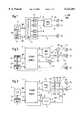
- FIG. 1is a block diagram of a conventional stereophonic sound system with three sound reproducers
- FIG. 2is a block diagram of one embodiment of the present invention with three sound reproducers
- FIG. 3is a block diagram of another embodiment of the present invention with two sound reproducers
- FIG. 4, 5 and 6show circuits for electronically increasing the stereo base width (that may be used for the modification circuit 4 of FIGS. 2 and 3);
- FIGS. 7, 8 and 9are block diagrams of filter circuits for obtaining a pseudostereo signal from a monaural signal (that may be used for the filter circuit 7 of FIG. 3).
- FIG. 1there is shown a block diagram of a conventional stereophonic sound system.
- This systemincludes a source 1 of stereophonic signals in the form of, for example, a multichannel decoder (e.g., the above-mentioned Dolby Surround Pro Logic processor), which is well known and described.
- the source 1provides a right signal R, a left signal L, a center signal C, and a surround signal S.
- a sound intermediate-frequency (SIF) stage 2produces a stereo multiplex signal SM, which is delivered to a stereo filter circuit 1.1.
- the filter circuit 1.1then forms the stereophonic signals R,L,C, and S.
- the signals produced by the SIF stagealso may be genuine three-dimensional signals.
- the processing by the filter circuit 1.1is digital, so that the individual signals have to be converted back to analog signal components by means of digital-to-analog converters 1.2.
- a control unit 3controls both the source 1 and the SIF stage 2 by use of control signals 3.1 and 3.2, respectively.
- the controldepends on whether the overall circuit is part of a television receiver or other equipment. With the control unit 3, it can also be predetermined how many sound reproducers, namely loudspeakers, are present or whether reproduction is to take place through headphones.
- the output signals from the filter circuit 1.1are switched and adapted to the actual number of reproducers.
- control signalcan change the output signals of the filter circuit (R,L,C and S) to correspond to the number of loud speakers or other reproducers in use.
- a widely used mode of operationis the above-mentioned phantom mode, in which the center signal C is evenly divided between the right and left signals R, L. In that mode, the surround signal S is not affected.
- a modification circuit 4When a stereo base is too narrow, this is compensated by a modification circuit 4.
- an "R+C” signal and an "L+C” signalare fed to the modification circuit.
- the center signal component Cis also weighted in the stereo filter circuit 1.1 as a function of frequency.
- the output of the modification circuit 4provides a modified right signal R1 and a modified left signal L1 which feed the right loudspeaker RL and the left loudspeaker LL, respectively.
- the surround signal Sis reproduced by means of a separate loudspeaker SL, which is best placed behind the listener.
- FIG. 2shows a first embodiment of the invention in block-diagram form.
- the source 1provides the stereophonic signals R, L, C, S as digital signals.
- new digital-to-analog interfaceshave to be defined in the respective signal paths. These are provided with digital-to-analog converters 1.2 disposed along each output path.
- digital-to-analog converterscan be used with the source 1 via separate inputs. With the circuit disclosed in FIG. 2, even with the use of a reduced number of sound reproducers, the source 1 need no longer be switched to the phantom mode.
- the center signal Cis weighted by means of a multiplier 5 and added to the modified right signal R1 via a first adder 6.1 and to the modified left signal L1 via a second adder 6.2.
- the new output signals R2 and L2feed the right and left loudspeakers, RL and LL, respectively.
- the weighting of the center signal Cis determined by a multiplication factor m delivered from unit 3.
- This processing of the center signal C only after the right and left signals have passed through the modification circuit (4)is advantageous over the circuit of FIG. 1 in that stereo-base widening is accomplished using only the pure right and left signals R,L. Falsifications by the center signal C cannot occur before the modification circuit 4 performs the stereo-base widening. This is particularly important if the SIF stage 2 transmits not only a stereo multiplex signal SM but also a signal with genuine three-dimensional components.
- FIG. 3shows another embodiment of the invention in which the number of sound reproducers is reduced to a single pair of loudspeakers RL, LL.
- This embodimentis especially suited for television receivers with a built-in right speaker and left speaker. Although the stereo base width is relatively small and no speaker for the surround signal is present, a satisfactory three-dimensional sound effect is obtained.
- the circuit of FIG. 3differs from the circuit of FIG. 2 in that the surround signal S is fed to a filter circuit 7.
- the filter circuit 7forms a pair of pseudostereo signals from the surround signal S, having right and left components, SR and SL.
- the right component SRis added to the signal R2 for the right speaker RL by means of a third adder 6.3
- the left component SL of the modified surround signalis added to the signal L2 for the left speaker LL by means of a fourth adder 6.4.
- the order 6.5, 6.6 of the adders in each signal path for forming the right signal R3 and left signal L3, respectively,is arbitrary.
- the filter circuit 7 for forming a pair of pseudostereo signals SR, SL from a single stereophonic signal Scan be very simple, for example, as shown in FIG. 7.
- the circuit of FIG. 7is known from a publication of The Audio Engineering Society entitled “Stereophonic Techniques--An Anthology of Reprinted Articles on Stereophonic Techniques” (New York, 1986), pages 64 to 69. This is a reprint of an article by M. R. Schroeder, "An Artificial Stereophonic Effect Obtained from a Single Audio Signal," JAES, Vol. 6, No. 2, pages 74 to 79 (April 1958). The same article also describes the improved circuits of FIGS. 8 and 9. The circuit of FIG. 7 is described in more detail below.
- FIG. 4shows the stereo-base-widening circuit of the stereo-modification circuit 4 of FIGS. 2 and 3.
- the directional effect for the left or right signal L1, R1is enhanced by coupling the higher frequency components, which are important for the three-dimensional impression, into the respective other channel in antiphase. This coupling is effected through a first combination stage K1 and a second combination stage K2, respectively.
- the signal componentsare filtered by respective high-pass filters HP and weighted with the factor k by a multiplier M.
- the antiphase conditionis established simply by implementing each of the two combiners K1, K2 with a subtracter whose subtrahend input is supplied with the high-pass-filtered signal from the opposite channel.
- FIG. 5shows another embodiment for the stereo-base-widening circuit 4.
- This circuitincludes an adder (ad) whose output signal L+R is the sum of the left and right signals L, R.
- the sum valuerepresents the signal component which actually does not contain any directional information.
- a signal componentis determined from this sum value with a high-pass filter HP and a multiplier M, and subtracted from the right and left signals R, L.
- Each of the two modified stereo signals R1, L1thus contains a smaller common signal L+R, so that the two signal sources seem to move apart without the actual positions of the loudspeakers being changed.
- a difference signal L-Ris formed from the right and left signals R, L by means of subtracter sb.
- a high-pass-filtered component of this difference signal L-Ris used to increase the independent left and right signal components in the respective signal paths in correct phase relation. This is accomplished with an adder K1 and a subtracter K2, respectively.
- an increase of the independent signal components in the two signal pathstakes place, giving the listener the impression of an increased stereo base width.
- Thisis a prior art circuit which generates from the monaural signal f(t) of a signal source 8 a pair of pseudostereo signals which is reproduced by a right speaker RL and a left speaker LL.
- the output signal f(t- ⁇ )+f(t)then feeds the right speaker RL.
- the output signal f(t- ⁇ ) of the delay element 9is combined with the original signal f(t) in a subtracter K4 to form a signal f(t- ⁇ )-f(t), which feeds the left speaker LL.
- the direction-dependent sound impressionis created by simulating the desired directional impression. This impression is created by the signals modified by the delay element 9, in conjunction with the different sound propagation times to the listener's right and left ears.
- FIG. 8shows another known example of how a pair of pseudostereo signals can be formed from a monaural signal f(t) via a filter bank BP.
- the original signal f(t)is resolved into a sequence of separate frequency ranges via a plurality of narrow bandpass filters 10.
- the outputs of the successive bandpass filters, numbered in FIG. 8 from 1 to 16,are alternately connected to the right and left speakers RL, LL. In this manner, a directional effect is obtained again.
- the formation of the pseudostereo signal from the original signal f(t)was further refined by connecting phase inverters 11 to the outputs of the individual bandpass filters 10 of the filter bank BP.
- This arrangementmakes it possible to connect each bandpass filter output to one of the two speakers RL, LL.
- the outputsare applied alternately through the respective phase inverters 11 associated with the respective bandpass filters 10.
- FIGS. 7, 8 and 9which only represent a selection of prior-art circuits, are described in the above reference as analog circuits. Their conversion to digital circuits is familiar to those skilled in the art and brings about the known advantages regarding stability. For the implementation of the stereophonic sound system, it is irrelevant whether the entire circuit or parts thereof are implemented in hardware and/or software.
Landscapes
- Physics & Mathematics (AREA)
- Engineering & Computer Science (AREA)
- Acoustics & Sound (AREA)
- Signal Processing (AREA)
- Stereophonic System (AREA)
- Reverberation, Karaoke And Other Acoustics (AREA)
- Circuit For Audible Band Transducer (AREA)
Abstract
Description
Claims (16)
Applications Claiming Priority (2)
| Application Number | Priority Date | Filing Date | Title |
|---|---|---|---|
| EP96107860 | 1996-05-17 | ||
| EP96107860AEP0808076B1 (en) | 1996-05-17 | 1996-05-17 | Surround sound system |
Publications (1)
| Publication Number | Publication Date |
|---|---|
| US6122381Atrue US6122381A (en) | 2000-09-19 |
Family
ID=8222788
Family Applications (1)
| Application Number | Title | Priority Date | Filing Date |
|---|---|---|---|
| US08/854,922Expired - LifetimeUS6122381A (en) | 1996-05-17 | 1997-05-13 | Stereophonic sound system |
Country Status (5)
| Country | Link |
|---|---|
| US (1) | US6122381A (en) |
| EP (1) | EP0808076B1 (en) |
| JP (1) | JPH1094099A (en) |
| KR (1) | KR100437174B1 (en) |
| DE (1) | DE59611450D1 (en) |
Cited By (14)
| Publication number | Priority date | Publication date | Assignee | Title |
|---|---|---|---|---|
| US20010014159A1 (en)* | 1999-12-02 | 2001-08-16 | Hiroshi Masuda | Audio reproducing apparatus |
| US20030002684A1 (en)* | 2000-06-28 | 2003-01-02 | Peavey Electronics Corporation | Sub-harmonic generator and stereo expansion processor |
| US20030040822A1 (en)* | 2001-05-07 | 2003-02-27 | Eid Bradley F. | Sound processing system using distortion limiting techniques |
| US6590983B1 (en)* | 1998-10-13 | 2003-07-08 | Srs Labs, Inc. | Apparatus and method for synthesizing pseudo-stereophonic outputs from a monophonic input |
| US6647119B1 (en)* | 1998-06-29 | 2003-11-11 | Microsoft Corporation | Spacialization of audio with visual cues |
| US20040005064A1 (en)* | 2002-05-03 | 2004-01-08 | Griesinger David H. | Sound event detection and localization system |
| WO2003103337A3 (en)* | 2002-05-30 | 2004-02-26 | Peavey Electronics Corp | Methods and apparatus for sub-harmonic generation, stereo expansion and distortion |
| US20040096068A1 (en)* | 2002-11-14 | 2004-05-20 | Hiroaki Sato | Audio effector circuit |
| US6879952B2 (en) | 2000-04-26 | 2005-04-12 | Microsoft Corporation | Sound source separation using convolutional mixing and a priori sound source knowledge |
| US7447321B2 (en) | 2001-05-07 | 2008-11-04 | Harman International Industries, Incorporated | Sound processing system for configuration of audio signals in a vehicle |
| US20080319564A1 (en)* | 2001-05-07 | 2008-12-25 | Harman International Industries, Incorporated | Sound processing system for configuration of audio signals in a vehicle |
| US20090285420A1 (en)* | 2008-05-16 | 2009-11-19 | Matthias Vierthaler | Device and Method for Producing a Surround Sound |
| US20110081032A1 (en)* | 2009-10-05 | 2011-04-07 | Harman International Industries, Incorporated | Multichannel audio system having audio channel compensation |
| US8363865B1 (en) | 2004-05-24 | 2013-01-29 | Heather Bottum | Multiple channel sound system using multi-speaker arrays |
Families Citing this family (4)
| Publication number | Priority date | Publication date | Assignee | Title |
|---|---|---|---|---|
| CN1227950C (en)* | 1999-05-13 | 2005-11-16 | 汤姆森特许公司 | stereo system |
| US6937737B2 (en)* | 2003-10-27 | 2005-08-30 | Britannia Investment Corporation | Multi-channel audio surround sound from front located loudspeakers |
| DE102021203632A1 (en) | 2021-04-13 | 2022-10-13 | Kaetel Systems Gmbh | Loudspeaker, signal processor, method for manufacturing the loudspeaker or method for operating the signal processor using dual-mode signal generation with two sound generators |
| DE102021203639A1 (en) | 2021-04-13 | 2022-10-13 | Kaetel Systems Gmbh | Loudspeaker system, method of manufacturing the loudspeaker system, public address system for a performance area and performance area |
Citations (7)
| Publication number | Priority date | Publication date | Assignee | Title |
|---|---|---|---|---|
| US3745254A (en)* | 1970-09-15 | 1973-07-10 | Victor Company Of Japan | Synthesized four channel stereo from a two channel source |
| US4408095A (en)* | 1980-03-04 | 1983-10-04 | Clarion Co., Ltd. | Acoustic apparatus |
| DE4030121A1 (en)* | 1989-10-11 | 1991-04-25 | Mitsubishi Electric Corp | MULTICHANNEL AUDIO REPRODUCTION DEVICE AND METHOD |
| EP0608930A1 (en)* | 1993-01-22 | 1994-08-03 | Koninklijke Philips Electronics N.V. | Digital 3-channel transmission of left and right stereo signals and a center signal |
| EP0630168A1 (en)* | 1993-06-15 | 1994-12-21 | NOKIA TECHNOLOGY GmbH | Improved Dolby prologic decoder |
| EP0637191A2 (en)* | 1993-07-30 | 1995-02-01 | Victor Company Of Japan, Ltd. | Surround signal processing apparatus |
| US5412731A (en)* | 1982-11-08 | 1995-05-02 | Desper Products, Inc. | Automatic stereophonic manipulation system and apparatus for image enhancement |
Family Cites Families (1)
| Publication number | Priority date | Publication date | Assignee | Title |
|---|---|---|---|---|
| KR920020952A (en)* | 1991-04-17 | 1992-11-21 | 이헌조 | Surround mode automatic switching circuit |
- 1996
- 1996-05-17EPEP96107860Apatent/EP0808076B1/ennot_activeExpired - Lifetime
- 1996-05-17DEDE59611450Tpatent/DE59611450D1/ennot_activeExpired - Lifetime
- 1997
- 1997-05-13USUS08/854,922patent/US6122381A/ennot_activeExpired - Lifetime
- 1997-05-16KRKR1019970018860Apatent/KR100437174B1/ennot_activeExpired - Fee Related
- 1997-05-19JPJP9129033Apatent/JPH1094099A/ennot_activeWithdrawn
Patent Citations (7)
| Publication number | Priority date | Publication date | Assignee | Title |
|---|---|---|---|---|
| US3745254A (en)* | 1970-09-15 | 1973-07-10 | Victor Company Of Japan | Synthesized four channel stereo from a two channel source |
| US4408095A (en)* | 1980-03-04 | 1983-10-04 | Clarion Co., Ltd. | Acoustic apparatus |
| US5412731A (en)* | 1982-11-08 | 1995-05-02 | Desper Products, Inc. | Automatic stereophonic manipulation system and apparatus for image enhancement |
| DE4030121A1 (en)* | 1989-10-11 | 1991-04-25 | Mitsubishi Electric Corp | MULTICHANNEL AUDIO REPRODUCTION DEVICE AND METHOD |
| EP0608930A1 (en)* | 1993-01-22 | 1994-08-03 | Koninklijke Philips Electronics N.V. | Digital 3-channel transmission of left and right stereo signals and a center signal |
| EP0630168A1 (en)* | 1993-06-15 | 1994-12-21 | NOKIA TECHNOLOGY GmbH | Improved Dolby prologic decoder |
| EP0637191A2 (en)* | 1993-07-30 | 1995-02-01 | Victor Company Of Japan, Ltd. | Surround signal processing apparatus |
Non-Patent Citations (5)
| Title |
|---|
| Carstens, "Effekthascherei", ELRAD, vol. No. 7, pp. 76-81, 1994. |
| Carstens, Effekthascherei , ELRAD, vol. No. 7, pp. 76 81, 1994.* |
| European Search Report for 96107860.7, dated Apr. 11, 1996.* |
| Schroeder, "An Artificial Stereophonic Effect Obtained from a Single Audio Signal", JAES, vol. 6, No. 2, pp. 74-79, Apr. 1958. |
| Schroeder, An Artificial Stereophonic Effect Obtained from a Single Audio Signal , JAES, vol. 6, No. 2, pp. 74 79, Apr. 1958.* |
Cited By (37)
| Publication number | Priority date | Publication date | Assignee | Title |
|---|---|---|---|---|
| US6647119B1 (en)* | 1998-06-29 | 2003-11-11 | Microsoft Corporation | Spacialization of audio with visual cues |
| US6590983B1 (en)* | 1998-10-13 | 2003-07-08 | Srs Labs, Inc. | Apparatus and method for synthesizing pseudo-stereophonic outputs from a monophonic input |
| US20040005066A1 (en)* | 1998-10-13 | 2004-01-08 | Kraemer Alan D. | Apparatus and method for synthesizing pseudo-stereophonic outputs from a monophonic input |
| US6711270B2 (en)* | 1998-12-02 | 2004-03-23 | Sony Corporation | Audio reproducing apparatus |
| US20010014159A1 (en)* | 1999-12-02 | 2001-08-16 | Hiroshi Masuda | Audio reproducing apparatus |
| US6879952B2 (en) | 2000-04-26 | 2005-04-12 | Microsoft Corporation | Sound source separation using convolutional mixing and a priori sound source knowledge |
| US7047189B2 (en) | 2000-04-26 | 2006-05-16 | Microsoft Corporation | Sound source separation using convolutional mixing and a priori sound source knowledge |
| US20050091042A1 (en)* | 2000-04-26 | 2005-04-28 | Microsoft Corporation | Sound source separation using convolutional mixing and a priori sound source knowledge |
| US20030002684A1 (en)* | 2000-06-28 | 2003-01-02 | Peavey Electronics Corporation | Sub-harmonic generator and stereo expansion processor |
| US7136493B2 (en) | 2000-06-28 | 2006-11-14 | Peavey Electronics Corporation | Sub-harmonic generator and stereo expansion processor |
| US20050147254A1 (en)* | 2000-06-28 | 2005-07-07 | Coats Elon R. | Sub-harmonic generator and stereo expansion processor |
| US7203320B2 (en) | 2000-06-28 | 2007-04-10 | Peavey Electronics Corporation | Sub-harmonic generator and stereo expansion processor |
| US7760890B2 (en) | 2001-05-07 | 2010-07-20 | Harman International Industries, Incorporated | Sound processing system for configuration of audio signals in a vehicle |
| US7447321B2 (en) | 2001-05-07 | 2008-11-04 | Harman International Industries, Incorporated | Sound processing system for configuration of audio signals in a vehicle |
| US7451006B2 (en) | 2001-05-07 | 2008-11-11 | Harman International Industries, Incorporated | Sound processing system using distortion limiting techniques |
| US20080319564A1 (en)* | 2001-05-07 | 2008-12-25 | Harman International Industries, Incorporated | Sound processing system for configuration of audio signals in a vehicle |
| US8031879B2 (en) | 2001-05-07 | 2011-10-04 | Harman International Industries, Incorporated | Sound processing system using spatial imaging techniques |
| US8472638B2 (en) | 2001-05-07 | 2013-06-25 | Harman International Industries, Incorporated | Sound processing system for configuration of audio signals in a vehicle |
| US20030040822A1 (en)* | 2001-05-07 | 2003-02-27 | Eid Bradley F. | Sound processing system using distortion limiting techniques |
| US7499553B2 (en) | 2002-05-03 | 2009-03-03 | Harman International Industries Incorporated | Sound event detector system |
| US20040005065A1 (en)* | 2002-05-03 | 2004-01-08 | Griesinger David H. | Sound event detection system |
| US20040005064A1 (en)* | 2002-05-03 | 2004-01-08 | Griesinger David H. | Sound event detection and localization system |
| US20040022392A1 (en)* | 2002-05-03 | 2004-02-05 | Griesinger David H. | Sound detection and localization system |
| US20040179697A1 (en)* | 2002-05-03 | 2004-09-16 | Harman International Industries, Incorporated | Surround detection system |
| US7567676B2 (en) | 2002-05-03 | 2009-07-28 | Harman International Industries, Incorporated | Sound event detection and localization system using power analysis |
| US7492908B2 (en) | 2002-05-03 | 2009-02-17 | Harman International Industries, Incorporated | Sound localization system based on analysis of the sound field |
| WO2003103337A3 (en)* | 2002-05-30 | 2004-02-26 | Peavey Electronics Corp | Methods and apparatus for sub-harmonic generation, stereo expansion and distortion |
| US20050041815A1 (en)* | 2002-05-30 | 2005-02-24 | Trammell Earnest Lloyd | Methods and apparatus for sub-harmonic generation, stereo expansion and distortion |
| US7171002B2 (en) | 2002-05-30 | 2007-01-30 | Peavey Electronics Corporation | Methods and apparatus for sub-harmonic generation, stereo expansion and distortion |
| US7242779B2 (en) | 2002-05-30 | 2007-07-10 | Peavey Electronics Corporation | Methods and apparatus for sub-harmonic generation, stereo expansion and distortion |
| US20040096068A1 (en)* | 2002-11-14 | 2004-05-20 | Hiroaki Sato | Audio effector circuit |
| US7460674B2 (en)* | 2002-11-14 | 2008-12-02 | Victor Company Of Japan, Ltd. | Audio effector circuit |
| US8363865B1 (en) | 2004-05-24 | 2013-01-29 | Heather Bottum | Multiple channel sound system using multi-speaker arrays |
| US20090285420A1 (en)* | 2008-05-16 | 2009-11-19 | Matthias Vierthaler | Device and Method for Producing a Surround Sound |
| US20110081032A1 (en)* | 2009-10-05 | 2011-04-07 | Harman International Industries, Incorporated | Multichannel audio system having audio channel compensation |
| US9100766B2 (en) | 2009-10-05 | 2015-08-04 | Harman International Industries, Inc. | Multichannel audio system having audio channel compensation |
| US9888319B2 (en) | 2009-10-05 | 2018-02-06 | Harman International Industries, Incorporated | Multichannel audio system having audio channel compensation |
Also Published As
| Publication number | Publication date |
|---|---|
| DE59611450D1 (en) | 2008-01-03 |
| EP0808076A1 (en) | 1997-11-19 |
| JPH1094099A (en) | 1998-04-10 |
| EP0808076B1 (en) | 2007-11-21 |
| KR970078741A (en) | 1997-12-12 |
| KR100437174B1 (en) | 2004-09-07 |
Similar Documents
| Publication | Publication Date | Title |
|---|---|---|
| US6122381A (en) | Stereophonic sound system | |
| KR940002166B1 (en) | Stereo synthesizer | |
| KR0135850B1 (en) | Sound reproducing device | |
| CA1234055A (en) | Stereo generator | |
| WO1995030322A1 (en) | Apparatus and method for adjusting levels between channels of a sound system | |
| EP0880301A2 (en) | Full sound enhancement using multi-input sound signals | |
| US20020057806A1 (en) | Sound field effect control apparatus and method | |
| CN102611966B (en) | For virtual ring around the loudspeaker array played up | |
| KR20140053831A (en) | Apparatus and method for a complete audio signal | |
| US5844993A (en) | Surround signal processing apparatus | |
| US6084970A (en) | Mono-stereo conversion device, an audio reproduction system using such a device and a mono-stereo conversion method | |
| JP2956545B2 (en) | Sound field control device | |
| JP2982627B2 (en) | Surround signal processing device and video / audio reproduction device | |
| WO2017165968A1 (en) | A system and method for creating three-dimensional binaural audio from stereo, mono and multichannel sound sources | |
| US6754352B2 (en) | Sound field production apparatus | |
| KR100424520B1 (en) | Signal modification circuit and method | |
| US5394472A (en) | Monaural to stereo sound translation process and apparatus | |
| US5550920A (en) | Voice canceler with simulated stereo output | |
| BG51469A3 (en) | System for synthesis of 3-dimensional sound image for video games | |
| JP2006033847A (en) | Sound reproduction apparatus and sound reproduction method for providing optimal virtual sound source | |
| JPH10304500A (en) | Sound field reproducing device | |
| EP1212923B1 (en) | Method and apparatus for generating a second audio signal from a first audio signal | |
| JPH1118199A (en) | Acoustic processor | |
| TW413995B (en) | Method and system for enhancing the audio image created by an audio signal | |
| US7796766B2 (en) | Audio center channel phantomizer |
Legal Events
| Date | Code | Title | Description |
|---|---|---|---|
| AS | Assignment | Owner name:DEUTSCHE ITT INDUSTRIES GMBH, GERMANY Free format text:ASSIGNMENT OF ASSIGNORS INTEREST;ASSIGNOR:WINTERER, MARTIN;REEL/FRAME:008556/0679 Effective date:19970505 | |
| AS | Assignment | Owner name:MICRONAS INTERMETALL GMBH, GERMANY Free format text:CHANGE OF NAME;ASSIGNOR:DEUTSCHE ITT INDUSTRIES GMBH;REEL/FRAME:010557/0361 Effective date:19971017 | |
| STCF | Information on status: patent grant | Free format text:PATENTED CASE | |
| FPAY | Fee payment | Year of fee payment:4 | |
| FEPP | Fee payment procedure | Free format text:PAYOR NUMBER ASSIGNED (ORIGINAL EVENT CODE: ASPN); ENTITY STATUS OF PATENT OWNER: LARGE ENTITY | |
| FPAY | Fee payment | Year of fee payment:8 | |
| AS | Assignment | Owner name:TRIDENT MICROSYSTEMS (FAR EAST) LTD.,CAYMAN ISLAND Free format text:ASSIGNMENT OF ASSIGNORS INTEREST;ASSIGNOR:MICRONAS GMBH;REEL/FRAME:024456/0453 Effective date:20100408 Owner name:TRIDENT MICROSYSTEMS (FAR EAST) LTD., CAYMAN ISLAN Free format text:ASSIGNMENT OF ASSIGNORS INTEREST;ASSIGNOR:MICRONAS GMBH;REEL/FRAME:024456/0453 Effective date:20100408 | |
| FPAY | Fee payment | Year of fee payment:12 | |
| SULP | Surcharge for late payment | Year of fee payment:11 | |
| AS | Assignment | Owner name:ENTROPIC COMMUNICATIONS, INC., CALIFORNIA Free format text:ASSIGNMENT OF ASSIGNORS INTEREST;ASSIGNORS:TRIDENT MICROSYSTEMS, INC.;TRIDENT MICROSYSTEMS (FAR EAST) LTD.;REEL/FRAME:028153/0530 Effective date:20120411 | |
| AS | Assignment | Owner name:ENTROPIC COMMUNICATIONS, INC., CALIFORNIA Free format text:MERGER AND CHANGE OF NAME;ASSIGNORS:EXCALIBUR ACQUISITION CORPORATION;ENTROPIC COMMUNICATIONS, INC.;ENTROPIC COMMUNICATIONS, INC.;REEL/FRAME:035706/0267 Effective date:20150430 | |
| AS | Assignment | Owner name:ENTROPIC COMMUNICATIONS, LLC, CALIFORNIA Free format text:MERGER AND CHANGE OF NAME;ASSIGNORS:ENTROPIC COMMUNICATIONS, INC.;EXCALIBUR SUBSIDIARY, LLC;ENTROPIC COMMUNICATIONS, LLC;REEL/FRAME:035717/0628 Effective date:20150430 | |
| AS | Assignment | Owner name:JPMORGAN CHASE BANK, N.A., AS COLLATERAL AGENT, IL Free format text:SECURITY AGREEMENT;ASSIGNORS:MAXLINEAR, INC.;ENTROPIC COMMUNICATIONS, LLC (F/K/A ENTROPIC COMMUNICATIONS, INC.);EXAR CORPORATION;REEL/FRAME:042453/0001 Effective date:20170512 Owner name:JPMORGAN CHASE BANK, N.A., AS COLLATERAL AGENT, ILLINOIS Free format text:SECURITY AGREEMENT;ASSIGNORS:MAXLINEAR, INC.;ENTROPIC COMMUNICATIONS, LLC (F/K/A ENTROPIC COMMUNICATIONS, INC.);EXAR CORPORATION;REEL/FRAME:042453/0001 Effective date:20170512 | |
| AS | Assignment | Owner name:MUFG UNION BANK, N.A., CALIFORNIA Free format text:SUCCESSION OF AGENCY (REEL 042453 / FRAME 0001);ASSIGNOR:JPMORGAN CHASE BANK, N.A.;REEL/FRAME:053115/0842 Effective date:20200701 | |
| AS | Assignment | Owner name:MAXLINEAR, INC., CALIFORNIA Free format text:RELEASE BY SECURED PARTY;ASSIGNOR:MUFG UNION BANK, N.A.;REEL/FRAME:056656/0204 Effective date:20210623 Owner name:EXAR CORPORATION, CALIFORNIA Free format text:RELEASE BY SECURED PARTY;ASSIGNOR:MUFG UNION BANK, N.A.;REEL/FRAME:056656/0204 Effective date:20210623 Owner name:MAXLINEAR COMMUNICATIONS LLC, CALIFORNIA Free format text:RELEASE BY SECURED PARTY;ASSIGNOR:MUFG UNION BANK, N.A.;REEL/FRAME:056656/0204 Effective date:20210623 |