US6121628A - Method, gas turbine, and combustor apparatus for sensing fuel quality - Google Patents
Method, gas turbine, and combustor apparatus for sensing fuel qualityDownload PDFInfo
- Publication number
- US6121628A US6121628AUS09/282,135US28213599AUS6121628AUS 6121628 AUS6121628 AUS 6121628AUS 28213599 AUS28213599 AUS 28213599AUS 6121628 AUS6121628 AUS 6121628A
- Authority
- US
- United States
- Prior art keywords
- fuel
- quality level
- light
- combustor
- gas turbine
- Prior art date
- Legal status (The legal status is an assumption and is not a legal conclusion. Google has not performed a legal analysis and makes no representation as to the accuracy of the status listed.)
- Expired - Lifetime
Links
- 239000000446fuelSubstances0.000titleclaimsabstractdescription216
- 238000000034methodMethods0.000titleclaimsdescription10
- 238000007599dischargingMethods0.000claimsabstractdescription3
- 238000002485combustion reactionMethods0.000claimsdescription25
- 238000001514detection methodMethods0.000claimsdescription7
- 238000010521absorption reactionMethods0.000claimsdescription4
- 230000005540biological transmissionEffects0.000claimsdescription4
- 238000012358sourcingMethods0.000claimsdescription4
- 238000009825accumulationMethods0.000claimsdescription2
- 238000012544monitoring processMethods0.000abstractdescription3
- 230000006870functionEffects0.000description10
- 239000003570airSubstances0.000description6
- 230000003287optical effectEffects0.000description6
- 230000031700light absorptionEffects0.000description4
- 239000012530fluidSubstances0.000description3
- 230000007246mechanismEffects0.000description3
- 239000010743number 2 fuel oilSubstances0.000description3
- 238000010586diagramMethods0.000description2
- 239000010742number 1 fuel oilSubstances0.000description2
- 239000003921oilSubstances0.000description2
- 230000000737periodic effectEffects0.000description2
- 230000008569processEffects0.000description2
- 230000009467reductionEffects0.000description2
- 230000008439repair processEffects0.000description2
- 238000005070samplingMethods0.000description2
- 238000012360testing methodMethods0.000description2
- 239000012080ambient airSubstances0.000description1
- 230000008901benefitEffects0.000description1
- 238000004364calculation methodMethods0.000description1
- 238000013500data storageMethods0.000description1
- 239000000975dyeSubstances0.000description1
- 239000003350keroseneSubstances0.000description1
- 238000005259measurementMethods0.000description1
- 239000000203mixtureSubstances0.000description1
- 238000012986modificationMethods0.000description1
- 230000004048modificationEffects0.000description1
- 239000010745number 4 fuel oilSubstances0.000description1
- 239000010747number 6 fuel oilSubstances0.000description1
- 238000012545processingMethods0.000description1
- 230000004044responseEffects0.000description1
- 238000012956testing procedureMethods0.000description1
Images


Classifications
- F—MECHANICAL ENGINEERING; LIGHTING; HEATING; WEAPONS; BLASTING
- F23—COMBUSTION APPARATUS; COMBUSTION PROCESSES
- F23N—REGULATING OR CONTROLLING COMBUSTION
- F23N5/00—Systems for controlling combustion
- F23N5/02—Systems for controlling combustion using devices responsive to thermal changes or to thermal expansion of a medium
- F23N5/08—Systems for controlling combustion using devices responsive to thermal changes or to thermal expansion of a medium using light-sensitive elements
- F23N5/082—Systems for controlling combustion using devices responsive to thermal changes or to thermal expansion of a medium using light-sensitive elements using electronic means
- F—MECHANICAL ENGINEERING; LIGHTING; HEATING; WEAPONS; BLASTING
- F23—COMBUSTION APPARATUS; COMBUSTION PROCESSES
- F23N—REGULATING OR CONTROLLING COMBUSTION
- F23N2221/00—Pretreatment or prehandling
- F23N2221/10—Analysing fuel properties, e.g. density, calorific
- F—MECHANICAL ENGINEERING; LIGHTING; HEATING; WEAPONS; BLASTING
- F23—COMBUSTION APPARATUS; COMBUSTION PROCESSES
- F23N—REGULATING OR CONTROLLING COMBUSTION
- F23N2235/00—Valves, nozzles or pumps
- F23N2235/12—Fuel valves
- F23N2235/16—Fuel valves variable flow or proportional valves
- F—MECHANICAL ENGINEERING; LIGHTING; HEATING; WEAPONS; BLASTING
- F23—COMBUSTION APPARATUS; COMBUSTION PROCESSES
- F23N—REGULATING OR CONTROLLING COMBUSTION
- F23N2241/00—Applications
- F23N2241/20—Gas turbines
Definitions
- This inventionrelates to a gas turbine having a combustor for burning fuel and, more specifically, to a combustor, such as a gas turbine combustor, for burning fuel and sensing fuel quality.
- the inventionalso relates to a method and combustor for burning fuel and sensing fuel quality.
- random, batch fuel testingis employed off-line to determine compliance with either a contract fuel or a fuel which meets the requisite combustor fuel specification.
- This testing procedurerequires a technician, a suitable fuel tester, and one or more laboratory devices to measure fuel quality.
- problemsmay result due to the periodic nature of the fuel sampling. For example, during periods when no fuel is sampled, it is possible for an inappropriate fuel to be used and, thus, potentially cause damage to high value components in a gas turbine.
- a combustorsuch as a gas turbine combustor
- a non-obtrusive, economical, real-time, on-line fuel sensing functionis, therefore, desirable to provide a combustor, such as a gas turbine combustor, with a non-obtrusive, economical, real-time, on-line fuel sensing function.
- a gas turbinecomprises a compressor for compressing air and discharging compressed air; a combustor for producing a hot gas by burning a fuel having a quality level in the compressed air; a turbine for expanding the hot gas produced by the combustor; means for delivering the fuel to the combustor; means for sensing the quality level of the fuel which is delivered to the combustor; and means for: stopping delivery of the fuel as a function of the quality level, or storing a history of the quality level.
- the means for sensing the quality levelincludes a light source, a light detector, and means for delivering the fuel between the light source and the light detector in order to transmit light through the fuel.
- the light detectormonitors absorption of the light which is transmitted through the fuel.
- the light source and the light detectorhave a distance therebetween, the light which is transmitted through the fuel is absorbed in proportion to the quality level and the distance, and the light detector has an output with a signal level which is inversely related to the quality level.
- the means for stopping delivery of the fuel or storing a history of the quality levelmay include means for stopping delivery of the fuel as a function of the quality level, and means for storing a history of the quality level.
- the means for storing a history of the quality levelincludes means for storing the quality level with respect to operating time of the gas turbine, and means for displaying the quality level.
- a combustor for burning fuel from a fuel supplycomprises means for burning the fuel; means for delivering the fuel from the fuel supply to the means for burning the fuel; means for sensing the quality level of the fuel which is delivered to the means for burning; and means for stopping delivery of the fuel as a function of the quality level, or storing a history of the quality level.
- a method of burning fuel in a combustorcomprises employing a fuel having a quality level; delivering the fuel to the combustor; sensing the quality level of the fuel which is delivered; burning the fuel which is delivered; and either stopping delivery of the fuel as a function of the quality level, or storing a history of the quality level.
- FIG. 1is a block diagram of a combustor including a fuel quality sensor in accordance with one embodiment of the invention
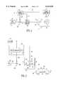
- FIG. 2is a block diagram of a gas turbine including a fuel quality sensor in accordance with another embodiment of the invention.
- FIG. 3is a flowchart of one embodiment of software suitable for execution by the control systems of FIGS. 1 and 2;
- FIG. 4is a flowchart of another embodiment of software suitable for execution by the control systems of FIGS. 1 and 2.
- combustorshall expressly include, but not be limited to, any combustion system in which a fuel is introduced and burned, such as, for example, internal or external combustion systems which produce a flame, a combustion turbine, a gas turbine combustor, a jet engine combustor, intermittent combustion systems such as a reciprocating engine, a boiler, an internal combustion engine, or any other heat engine.
- combustion zoneshall expressly include, but not be limited to, the chamber in which combustion occurs, such as, for example, the cylinder of a reciprocating engine; the single annular chamber or individual chambers of a gas turbine combustor; the combustion zone of a ramjet duct; the chamber, with a single venturi outlet, of a rocket; the space in a boiler furnace in which combustion of gaseous products from the fuel takes place; the space in an internal combustion engine above the piston in which combustion occurs; or any open or closed flame, and shall further expressly include all components that come into contact with hot gas products resulting from combustion, such as, for example, a turbine which receives hot gas from a gas turbine combustor.
- a gas turbine combustor 2includes an exemplary flame detection system 4 which comprises one or more optical flame detectors, such as detector 6, and a control system 8.
- exemplary flame detection system 4which comprises one or more optical flame detectors, such as detector 6, and a control system 8.
- detector 6such as detector 6
- control system 8a control system 8.
- the inventionis described herein in connection with exemplary gas turbine combustors, although the invention is applicable to a wide range of combustors with and without flame detection systems.
- the exemplary control system 8is connected to one or more fuel flow control valves, such as valve 10, in order to open, adjust, and/or close these valves to control the flow of fuel 12 to fuel nozzle 14.
- a combustion flame 16is established in combustion chamber 18 by burning the fuel 12 in the presence of air 20.
- signal 22is output.
- the control system 8closes the valve 10.
- fuel 12is no longer delivered to the combustion chamber 18 by fuel delivery system 24.
- That system 24has a fuel line 26 which operatively connects a fuel supply 28 to the valve 10, to a fuel quality sensor 30, and to the combustor 2. Without the delivery of the fuel 12, combustion is arrested.
- the exemplary control system 8is integrated with the flame detection system 4, although separate systems may be employed.
- the fuel quality sensor 30senses a quality level of the fuel 12 which is delivered to the combustor 2.
- the sensor 30includes a light source (e.g., broadband white light, a wavelength specific light, infrared light, monochromatic laser light) and a light detector.
- the light detectormonitors the absorption of light (e.g., reduction in amplitude) as light passes through the fuel 12. Light absorption may be approximated by Beer-Lambert calculations, whereby the light is absorbed in proportion to the fluid properties and the path length.
- Fuel qualitycan be determined by the amount of light absorption, either in broadband or in specific wavelengths. Lower quality fuels are typically opaque to most wavelengths of light. High quality fuels, such as kerosenes and No. 2 fuel oils, are reasonably transparent in specific wavelength regions.
- the gas turbine 66also includes a fuel delivery system 38, a control system 40, and a fuel quality sensor 42 for sensing the quality level of the fuel 44 which is delivered to the combustor 32.
- the sensor 42includes a light source, such as photo-emitter 46, for sourcing light 48; a mechanism 50 for passing the light 48 through the fuel 44; and a light detector, such as an optical detector or photo-detector 52, for detecting the light 48 which is transmitted through the fuel 44.
- the exemplary photo-detector 52has an output 54 with a fuel quality level signal 56 which is representative of the quality level of the fuel 44.
- the light sourceinclude an optical transmitter, such as a light emitting diode (LED) which emits a broadband white light, an LED or laser which emits a wavelength specific infrared light, or a laser which emits a monochromatic light for transmission through the fuel 44. Because some fuels are deliberately dyed using colored dyes, monochromatic laser light or wavelength specific light is preferably employed.
- the mechanism 50functions to deliver the fuel 44 through the conduit 58 thereof and, thus, between the photo-emitter 46 and the photo-detector 52 in order to transmit the light 48 through the fuel 44.
- the exemplary mechanism 50also includes a first window (or lens) 60 for admitting the light 48 from the photo-emitter 46 to the fuel 44 in the conduit 58, and a second window (or lens) 62 for admitting the light 48 from the fuel 44 to the photo-detector 52.
- the photo-emitter 46 and the photo-detector 52have a distance 64 therebetween which is determined by the conduit 58 and windows 60,62.
- the light 48 which passes through the fuel 44is absorbed in proportion to the quality level of the fuel 44 and the distance 64.
- the output signal 56 of the photo-detector 52has a signal level which is inversely related to the fuel quality level. In this manner, the sensor 42 monitors absorption of the light 48 which passes through the fuel 44.
- the photo-emitter 46 and photo-detector 52are employed in the fuel line 26 to continuously monitor the fuel quality level in real-time.
- the light 48 from the photo-emitter 46passes through the fuel 44, with the photo-detector 52 normally observing a reduction in measured light for the fuel fluid stream.
- low quality fuelse.g., No. 4 or No. 6 fuel oils
- high quality fuelse.g., No. 1 or No. 2 fuel oils
- information on fuel qualitycan be inferred from optical measurements.
- the absorptionis typically less than about 25% and is wavelength specific.
- transmissivityi.e., increased light absorption
- photo-detector output signal level 56if a low quality fuel enters into the fuel fluid stream, then there is a significant decrease in transmissivity (i.e., increased light absorption) and a corresponding decrease in the photo-detector output signal level 56.
- the continuous output 54is employed in the logic of the control system 40 (e.g., as an alarm, trip signal, and/or historically recorded parameter) to protect and/or monitor the unit and to shutdown or trip the combustor 32, thereby protecting the gas turbine 66 from running with lower quality fuel.
- the control system 40may also determine that the fuel 44 is of a specific grade and/or may monitor the fuel grade over the operating life of the gas turbine 66.
- the on-line fuel sensor 42may detect this type of fuel switch (or blend).
- Optical methodshave the unique advantage that a signal output may be logged electronically and, also, may be incorporated into the safety features of the combustor 32 (e.g., by causing a shutdown). In turn, downtime, damage, and costs due to operation with inappropriate fuels are minimized.
- the fuel sensor 42cooperates with a suitable control system 40 to sense the fuel quality level.
- the control system 40disables the fuel delivery system 38 as a function of the fuel quality level to, thereby, arrest combustion whenever quality levels are too low.
- the gas turbine 66is comprised of a compressor 67 into which ambient air 68 is drawn.
- the compressor 67discharges compressed air 69 to a combustor, such as the combustor 32, in which fuel, such as fuel 44, is burned to produce a hot gas 70.
- the hot gas 70is expanded in the turbine 71 and then discharged as exhaust gas 72.
- the exemplary control system 40not only protects the combustor 32 but, also, all hot section components, such as the exemplary turbine 71, from damage resulting from use of low quality or non-specification fuels.
- control system 40is preferably separate from a turbine control system (not shown), an integrated control system may be employed.
- the fuel sensors 30,42cooperate with the respective control systems 8,40 to sense the fuel quality level.
- the control systems 8,40disable the fuel delivery systems 24,38 and, thus, stop delivery of the fuel 12,44, respectively, as a function of the fuel quality level to, thereby, arrest combustion whenever the fuel quality is too low.
- the control systems 8,40also maintain an historical record of the fuel quality level.
- the routine 73obtains a fuel quality level (e.g., output signal 77 of sensor 30 having a signal level which is inversely related to the fuel quality level) from the corresponding fuel sensor and, then, compares the level to a predetermined (e.g., PT of FIG. 1) or suitably adjusted fuel quality threshold level (e.g., minimum allowable quality level).
- a fuel quality levele.g., output signal 77 of sensor 30 having a signal level which is inversely related to the fuel quality level
- a predeterminede.g., PT of FIG. 1
- suitably adjusted fuel quality threshold levele.g., minimum allowable quality level
- the predetermined level PTis preferably preselected to approximate a quality level of a type of fuel (e.g., kerosene, No. 1 fuel oil, No. 2 fuel oil). Then, the result of the comparison is employed to determine whether to disable the corresponding fuel delivery system and, thus, arrest combustion.
- a type of fuele.g., kerosene, No. 1 fuel oil, No. 2 fuel oil.
- the usersuitably inputs a new threshold level. Otherwise, if no adjustment was requested, and after 75, the fuel quality level is read, at 76, from the output signal 77 of the fuel sensor 30. Then, at 78, the level is compared to the threshold level. If the level is less than the threshold level, then, at 79, an alarm is generated. Next, at 80, output signal 81 is set to close the valve 10 and, thereby, stop delivery of the fuel 12. Otherwise, after 78, execution resumes at 74.
- the exemplary fuel sensor 30mounted in-line with the fuel line 26
- all of the burning fuel 12can be continuously screened, in real-time, for fuel quality.
- the alarmis generated.
- the alarmis employed to stop delivery of the fuel 12 as a function of the fuel quality level, and to shutdown the combustor 2, thereby reducing the risk of combustor damage.
- an exemplary software routine 82 for execution by the control systems 8 and 40 of FIGS. 1 and 2, respectively,is illustrated.
- processor-based control systems 8,40are shown, the invention is also applicable to a wide range of control devices (e.g., analog control systems, digital control systems, hybrid control systems).
- the routine 82obtains a fuel quality level from the corresponding sensor and, then, compares the level to a predetermined or suitably adjusted threshold level (e.g., AT of FIG. 2).
- the adjusted level ATis preferably selected in view of the quality level of a type of fuel. Then, the result of the comparison is employed to determine whether to disable the corresponding fuel delivery system and, thus, arrest combustion.
- routine 82 of FIG. 4is described with respect to the control system 40 of FIG. 2, although it is also applicable to the control system 8 of FIG. 1.
- Steps 84,86,88,100,102,104 of routine 82generally correspond to the respective steps 74,75,76,78,79,80 of routine 73 of FIG. 3.
- the usersuitably inputs a new accumulated threshold (e.g., AT of FIG. 2) level. Otherwise, if no adjustment was requested, and after 86, the level 56 is read, at 88, from the fuel sensor 42.
- a new accumulated thresholde.g., AT of FIG. 2
- the time of that readingis obtained, at 90, from a timer (T) 92.
- the level and timeare stored in a suitable data storage such as exemplary memory (M) 95 (e.g., disk, RAM).
- Mexemplary memory
- the accumulated levelis updated (e.g., the level 56 is integrated and/or averaged, the level 56 is inverted and integrated) and then stored, at 98, in the memory 95.
- an historical record of the quality level of the fuel 44is stored with respect to operating time of the combustor 32 and turbine 71 of the gas turbine 66.
- the accumulated levelmay be calculated from the initial time of operation of the gas turbine 66, over any previous time period (e.g., one second, one minute, one hour, one day, one month, one year), or since a previous time (e.g., since 1:07 pm) and/or date. In this manner, an historical record of the accumulation of the level 56 is updated and stored with respect to operating time.
- any previous time periode.g., one second, one minute, one hour, one day, one month, one year
- a previous timee.g., since 1:07 pm
- the accumulated fuel quality levelis compared to the accumulated threshold level. If the accumulated level is less than the threshold level (although if the level 56 is inverted, at 96, then the test is the accumulated level being greater than the threshold level), then, at 102, an alarm is generated. Next, at 104, output signal 106 is set to close valve 108 and, thereby, stop delivery of the fuel 44. Otherwise, after 100, at 110, it is determined whether display of the accumulated level has been requested. If so, at 112, a suitable history of the accumulated level, levels and/or time is output to display 114. Otherwise, if no output was requested, and after 112, execution resumes at 84.
- the display 114is employed by the control system 40 to display the historical record of the quality levels and/or accumulated level over the operating life of the gas turbine 66.
- an exemplary accumulated levelis disclosed, other variables (e.g., operating temperature, power output, load) may also be monitored, stored, displayed, and considered as part of the alarm logic.
- the exemplary fuel sensors of FIGS. 1 and 2are employed to continuously sense the fuel quality level of the respective combustors 2 and 32 in real-time. These systems have a relatively long useful life, result in lower repair costs and less frequent repairs. Since the detection of fuel quality occurs during the delivery and burning of the fuel, all of the fuel must be delivered to the combustors and, thus, all of the fuel to be burned can, theoretically, be checked for fuel quality. By monitoring fuel quality, and shutting off the fuel delivery system when inappropriate fuel quality is detected, the risk of damage is significantly reduced. Furthermore, continuous, real-time sensing protection may be incorporated into control logic to protect the gas turbine, without relying on laboratory results. This process is less expensive than other processes which employ a laboratory fuel analyzer.
- combustorsused in other types of machinery in which the detection of fuel quality is desirable.
- other combustorsmay employ different arrangements for fuel delivery, such as plural fuel flow control valves to start, adjust, and/or stop the flow of fuel to the combustor.
- Still other combustorsmay employ plural fuel lines, and, thus, plural fuel quality sensors may be employed.
- the present fuel sensing systemis in-line with the fuel that is pumped to the combustor and measures that fuel continuously.
- the systemmay be incorporated into the control logic to protect the gas turbine on-line by identifying when a non-specified fuel is being used and shutting down the unit, without relying on laboratory results.
- protection and monitoringare real time and continuous, and not batch, periodic or aperiodic. This provides a more reliable measure of the actual fuel type being employed, while being less expensive than batch sampling methods of fuel analysis.
- the quality informationcan be stored electronically and serve as an historical record of fuel quality, type and use.
Landscapes
- Engineering & Computer Science (AREA)
- Chemical & Material Sciences (AREA)
- Combustion & Propulsion (AREA)
- Mechanical Engineering (AREA)
- General Engineering & Computer Science (AREA)
- Investigating Or Analysing Materials By Optical Means (AREA)
Abstract
Description
Claims (26)
Priority Applications (1)
| Application Number | Priority Date | Filing Date | Title |
|---|---|---|---|
| US09/282,135US6121628A (en) | 1999-03-31 | 1999-03-31 | Method, gas turbine, and combustor apparatus for sensing fuel quality |
Applications Claiming Priority (1)
| Application Number | Priority Date | Filing Date | Title |
|---|---|---|---|
| US09/282,135US6121628A (en) | 1999-03-31 | 1999-03-31 | Method, gas turbine, and combustor apparatus for sensing fuel quality |
Publications (1)
| Publication Number | Publication Date |
|---|---|
| US6121628Atrue US6121628A (en) | 2000-09-19 |
Family
ID=23080251
Family Applications (1)
| Application Number | Title | Priority Date | Filing Date |
|---|---|---|---|
| US09/282,135Expired - LifetimeUS6121628A (en) | 1999-03-31 | 1999-03-31 | Method, gas turbine, and combustor apparatus for sensing fuel quality |
Country Status (1)
| Country | Link |
|---|---|
| US (1) | US6121628A (en) |
Cited By (20)
| Publication number | Priority date | Publication date | Assignee | Title |
|---|---|---|---|---|
| EP1645804A1 (en)* | 2004-10-11 | 2006-04-12 | Siemens Aktiengesellschaft | Method for operating a burner, especially a gas turbine burner, and apparatus for executing the method |
| US20060283193A1 (en)* | 2005-02-05 | 2006-12-21 | Nilsson Ulf E | Fuel injection system and purging method |
| CN100359160C (en)* | 2001-11-27 | 2008-01-02 | 艾劳埃斯·乌本 | Method for monitoring a sensor |
| WO2008064628A1 (en)* | 2006-11-29 | 2008-06-05 | Enerday Gmbh | Method for controlling a fuel cell system associated with an air-conditioning system, and air-conditioning system for the auxiliary air-conditioning of a motor vehicle |
| US20080230146A1 (en)* | 2007-01-16 | 2008-09-25 | Veeder-Root Company | Automated Fuel Quality Detection and Dispenser Control System and Method, Particularly for Aviation Fueling Applications |
| US20090050034A1 (en)* | 2007-08-22 | 2009-02-26 | Jaroslaw Dabrowski | System for automatic feeding of furnaces with liquid fuel |
| US20090101822A1 (en)* | 2007-10-18 | 2009-04-23 | General Electric Company | System and method for sensing fuel moisturization |
| US20100007874A1 (en)* | 2006-08-21 | 2010-01-14 | Sp3H | Method for ensuring the safety of the components of the drive train of a vehicle following the deterioration of the fuel |
| US20100175466A1 (en)* | 2003-09-25 | 2010-07-15 | Casio Computer Co., Ltd. | Power generation device, fuel package, and remaining fuel amount measuring device |
| ITMI20090153A1 (en)* | 2009-02-06 | 2010-08-07 | Ansaldo Energia Spa | DEVICE AND METHOD TO ADJUST THE GAS SUPPLY TO A COMBUSTION CHAMBER AND GAS TURBINE SYSTEM INCLUDING SUCH A DEVICE |
| US20100211289A1 (en)* | 2007-09-26 | 2010-08-19 | Toyota Jidosha Kabushiki Kaisha | Device and method for detecting degradation of fuel for internal combustion engine |
| US20110095190A1 (en)* | 2009-10-26 | 2011-04-28 | General Electric Company | Elemental composition detection system and method |
| US20120023894A1 (en)* | 2010-07-28 | 2012-02-02 | General Electric Company | Systems, methods, and apparatus for monitoring corrosion or corrosive contaminants associated with liquid fuel |
| US20130098053A1 (en)* | 2011-10-20 | 2013-04-25 | Michael John Hughes | Systems and methods for use in operating turbine engines |
| US20150075170A1 (en)* | 2013-09-17 | 2015-03-19 | General Electric Company | Method and system for augmenting the detection reliability of secondary flame detectors in a gas turbine |
| US20150346133A1 (en)* | 2014-05-27 | 2015-12-03 | Electronics And Telecommunications Research Institute | Apparatus and method of discriminating reformulated fuel |
| US9335314B2 (en)* | 2013-11-19 | 2016-05-10 | Electronics And Telecommunications Research Institute | Optical circuit-type reformulated fuel detecting sensor device and method for manufacturing sensor element thereof |
| US9530290B2 (en) | 2013-01-18 | 2016-12-27 | Fuel Guard Systems Corporation | Apparatuses and methods for providing visual indication of dynamic process fuel quality delivery conditions with use of multiple colored indicator lights |
| WO2017152845A1 (en)* | 2016-03-09 | 2017-09-14 | 西门子公司 | Combustion monitoring method, device and system for natural gas burner |
| US10364139B2 (en) | 2015-01-29 | 2019-07-30 | Ray Hutchinson | Automated water and particle detection for dispensing fuel including aviation fuel, and related apparatuses, systems, and methods |
Citations (16)
| Publication number | Priority date | Publication date | Assignee | Title |
|---|---|---|---|---|
| US4043742A (en)* | 1976-05-17 | 1977-08-23 | Environmental Data Corporation | Automatic burner monitor and control for furnaces |
| US4816695A (en)* | 1987-08-31 | 1989-03-28 | Lavin Thomas N | Optical fluid detector |
| US5218212A (en)* | 1989-11-24 | 1993-06-08 | Mitsubishi Denki Kabushiki Kaisha | Device for optically detecting a chemical change in fluid |
| US5239860A (en)* | 1991-05-13 | 1993-08-31 | General Motors Corporation | Sensor for measuring alcohol content of alcohol/gasoline fuel mixtures |
| US5262645A (en)* | 1991-09-03 | 1993-11-16 | General Motors Corporation | Sensor for measuring alcohol content of alcohol gasoline fuel mixtures |
| US5349189A (en)* | 1990-04-09 | 1994-09-20 | Ashland Oil, Inc. | Process and apparatus for analysis of hydrocarbons by near-infrared spectroscopy |
| US5348645A (en)* | 1990-12-11 | 1994-09-20 | Ashland Oil, Inc. | Determination of aromatics in hydrocarbons by near infrared spectroscopy |
| US5361586A (en)* | 1993-04-15 | 1994-11-08 | Westinghouse Electric Corporation | Gas turbine ultra low NOx combustor |
| US5517427A (en)* | 1994-03-30 | 1996-05-14 | On-Site Analysis, Inc. | On-site oil analyzer |
| US5637881A (en)* | 1993-04-01 | 1997-06-10 | High Yield Technology, Inc. | Method to detect non-spherical particles using orthogonally polarized light |
| US5672887A (en)* | 1995-11-29 | 1997-09-30 | Shaw; Benjamin G. | Optical detector for air in fluid line the same |
| US5672873A (en)* | 1995-07-13 | 1997-09-30 | Cosmo Research Institute | Method and apparatus for quantitative determination of components in residual fuel oils |
| US5708272A (en)* | 1996-05-03 | 1998-01-13 | Intevep, S.A. | Apparatus for determining a parameter of a substance, especially a hydrocarbon |
| US5742064A (en)* | 1996-04-24 | 1998-04-21 | Infante; David A. | System for detecting impurities contained in a flowing petroleum product |
| US5791145A (en)* | 1994-09-30 | 1998-08-11 | Cooper Cameron Corporation | Natural gas engine control system |
| US5818063A (en)* | 1997-03-20 | 1998-10-06 | Bsh Bosch Und Siemens Hausgeraete Gmbh | Optical sensor for contamination in a circulating cleaning fluid |
- 1999
- 1999-03-31USUS09/282,135patent/US6121628A/ennot_activeExpired - Lifetime
Patent Citations (19)
| Publication number | Priority date | Publication date | Assignee | Title |
|---|---|---|---|---|
| US4043742A (en)* | 1976-05-17 | 1977-08-23 | Environmental Data Corporation | Automatic burner monitor and control for furnaces |
| US4816695A (en)* | 1987-08-31 | 1989-03-28 | Lavin Thomas N | Optical fluid detector |
| US5218212A (en)* | 1989-11-24 | 1993-06-08 | Mitsubishi Denki Kabushiki Kaisha | Device for optically detecting a chemical change in fluid |
| US5349189A (en)* | 1990-04-09 | 1994-09-20 | Ashland Oil, Inc. | Process and apparatus for analysis of hydrocarbons by near-infrared spectroscopy |
| US5349188A (en)* | 1990-04-09 | 1994-09-20 | Ashland Oil, Inc. | Near infrared analysis of piano constituents and octane number of hydrocarbons |
| US5348645A (en)* | 1990-12-11 | 1994-09-20 | Ashland Oil, Inc. | Determination of aromatics in hydrocarbons by near infrared spectroscopy |
| US5239860A (en)* | 1991-05-13 | 1993-08-31 | General Motors Corporation | Sensor for measuring alcohol content of alcohol/gasoline fuel mixtures |
| US5262645A (en)* | 1991-09-03 | 1993-11-16 | General Motors Corporation | Sensor for measuring alcohol content of alcohol gasoline fuel mixtures |
| US5637881A (en)* | 1993-04-01 | 1997-06-10 | High Yield Technology, Inc. | Method to detect non-spherical particles using orthogonally polarized light |
| US5361586A (en)* | 1993-04-15 | 1994-11-08 | Westinghouse Electric Corporation | Gas turbine ultra low NOx combustor |
| US5713206A (en)* | 1993-04-15 | 1998-02-03 | Westinghouse Electric Corporation | Gas turbine ultra low NOx combustor |
| US5537336A (en)* | 1994-03-30 | 1996-07-16 | On-Site Analysis, Inc. | On-site oil analyzer |
| US5517427A (en)* | 1994-03-30 | 1996-05-14 | On-Site Analysis, Inc. | On-site oil analyzer |
| US5791145A (en)* | 1994-09-30 | 1998-08-11 | Cooper Cameron Corporation | Natural gas engine control system |
| US5672873A (en)* | 1995-07-13 | 1997-09-30 | Cosmo Research Institute | Method and apparatus for quantitative determination of components in residual fuel oils |
| US5672887A (en)* | 1995-11-29 | 1997-09-30 | Shaw; Benjamin G. | Optical detector for air in fluid line the same |
| US5742064A (en)* | 1996-04-24 | 1998-04-21 | Infante; David A. | System for detecting impurities contained in a flowing petroleum product |
| US5708272A (en)* | 1996-05-03 | 1998-01-13 | Intevep, S.A. | Apparatus for determining a parameter of a substance, especially a hydrocarbon |
| US5818063A (en)* | 1997-03-20 | 1998-10-06 | Bsh Bosch Und Siemens Hausgeraete Gmbh | Optical sensor for contamination in a circulating cleaning fluid |
Cited By (36)
| Publication number | Priority date | Publication date | Assignee | Title |
|---|---|---|---|---|
| CN100359160C (en)* | 2001-11-27 | 2008-01-02 | 艾劳埃斯·乌本 | Method for monitoring a sensor |
| US7918132B2 (en)* | 2003-09-25 | 2011-04-05 | Casio Computer Co., Ltd. | Power generation device, fuel package, and remaining fuel amount measuring device |
| US7824789B2 (en) | 2003-09-25 | 2010-11-02 | Casio Computer Co., Ltd. | Power generation device, fuel package, and remaining fuel amount measuring device |
| US20100178594A1 (en)* | 2003-09-25 | 2010-07-15 | Casio Computer Co., Ltd. | Power generation device, fuel package, and remaining fuel amount measuring device |
| US20100175466A1 (en)* | 2003-09-25 | 2010-07-15 | Casio Computer Co., Ltd. | Power generation device, fuel package, and remaining fuel amount measuring device |
| EP1645804A1 (en)* | 2004-10-11 | 2006-04-12 | Siemens Aktiengesellschaft | Method for operating a burner, especially a gas turbine burner, and apparatus for executing the method |
| US7818955B2 (en)* | 2005-02-05 | 2010-10-26 | Alstom Technology Ltd | Fuel injection system and purging method |
| US20060283193A1 (en)* | 2005-02-05 | 2006-12-21 | Nilsson Ulf E | Fuel injection system and purging method |
| US8148692B2 (en)* | 2006-08-21 | 2012-04-03 | Sp3H | Method for ensuring the safety of the components of the drive train of a vehicle following the deterioration of the fuel |
| US20100007874A1 (en)* | 2006-08-21 | 2010-01-14 | Sp3H | Method for ensuring the safety of the components of the drive train of a vehicle following the deterioration of the fuel |
| EP1939966A1 (en)* | 2006-11-29 | 2008-07-02 | Enerday GmbH | Method for operating a fuel cell system assigned to an air conditioning system and air conditioning for independent air conditioning of a motor vehicle |
| WO2008064628A1 (en)* | 2006-11-29 | 2008-06-05 | Enerday Gmbh | Method for controlling a fuel cell system associated with an air-conditioning system, and air-conditioning system for the auxiliary air-conditioning of a motor vehicle |
| US8720499B2 (en) | 2007-01-16 | 2014-05-13 | Fuel Guard Systems Corporation | Automated fuel quality detection and dispenser control system and method, particularly for aviation fueling applications |
| US9216892B2 (en) | 2007-01-16 | 2015-12-22 | Fuel Guard Systems Corporation | Automated fuel quality detection and dispenser control system and method, particularly for aviation fueling applications |
| US20080230146A1 (en)* | 2007-01-16 | 2008-09-25 | Veeder-Root Company | Automated Fuel Quality Detection and Dispenser Control System and Method, Particularly for Aviation Fueling Applications |
| US20090050034A1 (en)* | 2007-08-22 | 2009-02-26 | Jaroslaw Dabrowski | System for automatic feeding of furnaces with liquid fuel |
| US20100211289A1 (en)* | 2007-09-26 | 2010-08-19 | Toyota Jidosha Kabushiki Kaisha | Device and method for detecting degradation of fuel for internal combustion engine |
| US8347828B2 (en)* | 2007-09-26 | 2013-01-08 | Toyota Jidosha Kabushiki Kaisha | Device and method for detecting degradation of fuel for internal combustion engine |
| US20090101822A1 (en)* | 2007-10-18 | 2009-04-23 | General Electric Company | System and method for sensing fuel moisturization |
| ITMI20090153A1 (en)* | 2009-02-06 | 2010-08-07 | Ansaldo Energia Spa | DEVICE AND METHOD TO ADJUST THE GAS SUPPLY TO A COMBUSTION CHAMBER AND GAS TURBINE SYSTEM INCLUDING SUCH A DEVICE |
| US8058621B2 (en) | 2009-10-26 | 2011-11-15 | General Electric Company | Elemental composition detection system and method |
| CN102053095A (en)* | 2009-10-26 | 2011-05-11 | 通用电气公司 | Element composition detection system and method |
| US20110095190A1 (en)* | 2009-10-26 | 2011-04-28 | General Electric Company | Elemental composition detection system and method |
| CN105203573A (en)* | 2009-10-26 | 2015-12-30 | 通用电气公司 | Elemental composition detection system and method |
| US20120023894A1 (en)* | 2010-07-28 | 2012-02-02 | General Electric Company | Systems, methods, and apparatus for monitoring corrosion or corrosive contaminants associated with liquid fuel |
| US8589087B2 (en)* | 2010-07-28 | 2013-11-19 | General Electric Company | Systems, methods, and apparatus for monitoring corrosion or corrosive contaminants associated with liquid fuel |
| US20130098053A1 (en)* | 2011-10-20 | 2013-04-25 | Michael John Hughes | Systems and methods for use in operating turbine engines |
| US8997452B2 (en)* | 2011-10-20 | 2015-04-07 | General Electric Company | Systems and methods for regulating fuel and reactive fluid supply in turbine engines |
| US9530290B2 (en) | 2013-01-18 | 2016-12-27 | Fuel Guard Systems Corporation | Apparatuses and methods for providing visual indication of dynamic process fuel quality delivery conditions with use of multiple colored indicator lights |
| US20150075170A1 (en)* | 2013-09-17 | 2015-03-19 | General Electric Company | Method and system for augmenting the detection reliability of secondary flame detectors in a gas turbine |
| US9335314B2 (en)* | 2013-11-19 | 2016-05-10 | Electronics And Telecommunications Research Institute | Optical circuit-type reformulated fuel detecting sensor device and method for manufacturing sensor element thereof |
| US20150346133A1 (en)* | 2014-05-27 | 2015-12-03 | Electronics And Telecommunications Research Institute | Apparatus and method of discriminating reformulated fuel |
| US9811063B2 (en)* | 2014-05-27 | 2017-11-07 | Electronics And Telecommunications Research Institute | Apparatus and method of discriminating reformulated fuel |
| US10364139B2 (en) | 2015-01-29 | 2019-07-30 | Ray Hutchinson | Automated water and particle detection for dispensing fuel including aviation fuel, and related apparatuses, systems, and methods |
| US10752490B2 (en) | 2015-01-29 | 2020-08-25 | Ray Hutchinson | Automated water and particle detection for dispensing fuel including aviation fuel |
| WO2017152845A1 (en)* | 2016-03-09 | 2017-09-14 | 西门子公司 | Combustion monitoring method, device and system for natural gas burner |
Similar Documents
| Publication | Publication Date | Title |
|---|---|---|
| US6121628A (en) | Method, gas turbine, and combustor apparatus for sensing fuel quality | |
| US6268913B1 (en) | Method and combustor apparatus for sensing the level of a contaminant within a combustion flame | |
| US8371102B1 (en) | Combustor control based on fuel modulation and passive optical sensors | |
| RU2421662C2 (en) | Gas turbine engine and method of detecting partial tail cone extinction of gas turbine engine | |
| JPH07500897A (en) | Systems, devices and methods for controlling combustion processes and detection devices and flues used therein | |
| JP4980361B2 (en) | Burner tip fouling / corrosion detector in combustion equipment | |
| US4233596A (en) | Flare monitoring apparatus | |
| US20070234730A1 (en) | Method and apparatus for monitoring combustion instability and other performance deviations in turbine engines and like combustion systems | |
| US20020099474A1 (en) | Combustion diagnostics method and system | |
| CN103154440A (en) | Method of detecting predetermined condition in gas turbine and failure detection system for gas turbine | |
| JPH06258170A (en) | Apparatus for detecting gas leakage | |
| US9255835B2 (en) | System for remote vibration detection on combustor basket and transition in gas turbines | |
| US7818955B2 (en) | Fuel injection system and purging method | |
| US5761092A (en) | Gas burner monitor and diagnostic apparatus | |
| JP2014163383A (en) | Methods and apparatus for rapid sensing of fuel wobbe index | |
| JP4113728B2 (en) | Flame-out detection method, flame-out detection apparatus, and gas turbine engine | |
| US5612904A (en) | Oil burner monitor and diagnostic apparatus | |
| JP3616070B2 (en) | Gas temperature non-contact measuring device | |
| US8125646B2 (en) | Apparatus and methods for monitoring combustion dynamics in a gas turbine engine | |
| CN113423991A (en) | Burner arrangement and method for operating a burner arrangement | |
| JPH10207534A (en) | Method and device for piping abnormality detection of high-temperature gas piping | |
| US20210356126A1 (en) | Burner flame stabilization method and system | |
| US9702302B2 (en) | Methods and sensor module for controlling combustion emission parameters in a combustion system | |
| EP4397907A1 (en) | Combustion sensor control | |
| NL2034860B1 (en) | Flashback detection sensor, burner control system and method for controlling a burner control system. |
Legal Events
| Date | Code | Title | Description |
|---|---|---|---|
| AS | Assignment | Owner name:SIEMENS WESTINGHOUSE POWER CORPORATION, NEW JERSEY Free format text:ASSIGNMENT OF ASSIGNORS INTEREST;ASSIGNOR:RISING, BRUCE W.;REEL/FRAME:009880/0562 Effective date:19990330 | |
| STCF | Information on status: patent grant | Free format text:PATENTED CASE | |
| FPAY | Fee payment | Year of fee payment:4 | |
| AS | Assignment | Owner name:SIEMENS POWER GENERATION, INC., FLORIDA Free format text:CHANGE OF NAME;ASSIGNOR:SIEMENS WESTINGHOUSE POWER CORPORATION;REEL/FRAME:016996/0491 Effective date:20050801 | |
| FPAY | Fee payment | Year of fee payment:8 | |
| AS | Assignment | Owner name:SIEMENS ENERGY, INC., FLORIDA Free format text:CHANGE OF NAME;ASSIGNOR:SIEMENS POWER GENERATION, INC.;REEL/FRAME:022482/0740 Effective date:20081001 Owner name:SIEMENS ENERGY, INC.,FLORIDA Free format text:CHANGE OF NAME;ASSIGNOR:SIEMENS POWER GENERATION, INC.;REEL/FRAME:022482/0740 Effective date:20081001 | |
| FPAY | Fee payment | Year of fee payment:12 | |
| AS | Assignment | Owner name:CRESCENT COVE CAPITAL II, LP, CALIFORNIA Free format text:SECURITY INTEREST;ASSIGNOR:GEO SEMICONDUCTOR INC.;REEL/FRAME:049337/0040 Effective date:20190515 | |
| AS | Assignment | Owner name:GEO SEMICONDUCTOR, INC., CALIFORNIA Free format text:RELEASE BY SECURED PARTY;ASSIGNOR:CRESCENT COVE CAPITAL II, LP;REEL/FRAME:060840/0079 Effective date:20220721 |