US6119044A - Cochlear electrode array with positioning stylet - Google Patents
Cochlear electrode array with positioning styletDownload PDFInfo
- Publication number
- US6119044A US6119044AUS09/259,199US25919999AUS6119044AUS 6119044 AUS6119044 AUS 6119044AUS 25919999 AUS25919999 AUS 25919999AUS 6119044 AUS6119044 AUS 6119044A
- Authority
- US
- United States
- Prior art keywords
- electrode
- electrode array
- array
- flexible carrier
- wire
- Prior art date
- Legal status (The legal status is an assumption and is not a legal conclusion. Google has not performed a legal analysis and makes no representation as to the accuracy of the status listed.)
- Expired - Fee Related
Links
Images


Classifications
- A—HUMAN NECESSITIES
- A61—MEDICAL OR VETERINARY SCIENCE; HYGIENE
- A61N—ELECTROTHERAPY; MAGNETOTHERAPY; RADIATION THERAPY; ULTRASOUND THERAPY
- A61N1/00—Electrotherapy; Circuits therefor
- A61N1/02—Details
- A61N1/04—Electrodes
- A61N1/05—Electrodes for implantation or insertion into the body, e.g. heart electrode
- A61N1/0526—Head electrodes
- A61N1/0541—Cochlear electrodes
Definitions
- the present inventionrelates to implantable stimulation devices, e.g., cochlear prosthesis used to electrically stimulate the auditory nerve, and more particularly to an electrode array for insertion into the cochlea that hugs the modiolus of the cochlea, and further wherein the electrode contacts of the electrode array are on that side of the electrode array closest to the modiolus, thereby allowing the ganglion cells within the modiolus to be stimulated with minimal power consumption. That is, when the array is implanted into the cochlea, the electrode side of the array may be positioned closest to the modiolar wall, thereby placing all of the individual electrode contacts in close proximity to the ganglion cells and thereby in close proximity to the auditory nerve fibers.
- implantable stimulation devicese.g., cochlear prosthesis used to electrically stimulate the auditory nerve
- an electrode arrayfor insertion into the cochlea that hugs the modiolus of the cochlea
- the electrode contacts of the electrode arrayare on that side of the electrode array
- Hearing losswhich may be due to many different causes, is generally of two types: conductive and sensorineural.
- conductive hearing lossoccurs where the normal mechanical pathways for sound to reach the hair cells in the cochlea are impeded, for example, by damage to the ossicles.
- Conductive hearing lossmay often be helped by use of conventional hearing aids, which amplify sound so that acoustic information does reach the cochlea and the hair cells.
- Some types of conductive hearing lossare also amenable to alleviation by surgical procedures.
- cochlear implant systemswhich seek to bypass the hair cells in the cochlea (the hair cells are located in the vicinity of the radially outer wall of the cochlea) by presenting electrical stimulation to the auditory nerve fibers directly, leading to the perception of sound in the brain and at least partial restoration of hearing function.
- the common denominator in most of these cochlear prosthesis systemshas been the implantation into the cochlea of electrodes which are responsive to a suitable external source of electrical stimuli and which are intended to transmit those stimuli to the ganglion cells and thereby to the auditory nerve fibers.
- a cochlear prosthesisoperates by direct electrical stimulation of the auditory nerve cells, bypassing the defective cochlear hair cells that normally transduce acoustic energy into electrical activity in such nerve cells.
- the electronic circuitry and the electrode array of the cochlear prosthesisperforms the function of the separating the acoustic signal into a number of parallel channels of information, each representing the intensity of a narrow band of frequencies within the acoustic spectrum. Ideally, each channel of information would be conveyed selectively to the subset of auditory nerve cells that normally transmitted information about that frequency band to the brain.
- Those nerve cellsare arranged in an orderly tonotopic sequence, from high frequencies at the basal end of the cochlear spiral to progressively lower frequencies towards the apex. In practice, this goal tends to be difficult to realize because of the anatomy of the cochlea.
- the scala tympanione of the three parallel ducts that, in parallel, make up the spiral-shaped cochlea, provides the best location for implantation of an electrode array used with a cochlear prosthesis.
- the electrode array to be implanted in this sitetypically consists of a thin, elongated, flexible carrier containing several longitudinally disposed and separately connected stimulating electrode contacts, perhaps 6-30 in number. Such electrode array is pushed into the scala tympani duct to a depth of about 20-30 mm via a surgical opening made in the round window at the basal end of the duct.
- electrical currentis passed into the fluids and tissues immediately surrounding the individual electrode contacts in order to create transient potential gradients that, if sufficiently strong, cause the nearby auditory nerve fibers to generate action potentials.
- the auditory nerve fibersarise from cell bodies located in the spiral ganglion, which lies in the bone, or modiolus, adjacent to the scala tympani on the inside wall of its spiral course. Because the density of electrical current flowing through volume conductors such as tissues and fluids tends to be highest near the electrode contact that is the source of such current, stimulation at one contact site tends to activate selectively those spiral ganglion cells and their auditory nerve fibers that are closest to that contact site.
- the electrode contactsare positioned as close to the ganglion cells as possible.
- the electrode array, after implant,should preferably hug the modiolar wall, and that the individual electrodes of the electrode array should be positioned on or near that surface of the electrode array which is closest to the modiolar wall.
- an intracochlear electrode arraythat includes a spiral-shaped resilient carrier which generally has a natural spiral shape so that it better conforms to the shape of the scala tympani. See, e.g., U.S. Pat. No. 4,819,647.
- the '647 U.S. patentis incorporated herein by reference.
- the electrode array taught in the above-referenced '219 and '585 patentshas the right idea, i.e., to force the electrode carrier into a close hugging engagement with the modiolus, it does so only by use of an additional element that makes manufacture of the lead more difficult and expensive, and only through application of an additional pushing force which is applied to an electrode structure after it is already fully inserted into the cochlea.
- additional pushing forcemay easily cause damage to the delicate scala tympani.
- the entire electrode arraymay twist during the insertion process, or when the additional pushing force is applied, thereby causing the electrode contacts to twist and/or be forced away from the modiolus, rather than in a hugging relationship therewith.
- the present inventionaddresses the above and other needs by providing a universal electrode array, adapted for insertion into either a left or right cochlea, which assumes a spiral shape after insertion.
- all of the electrode contactsare spaced apart along one edge or side of the array, termed the "medial side", which medial side resides on the inside of the spiral.
- all of the electrode contactsare placed in close proximity to the modiolar wall, where they are closest to the ganglion cells that are to be stimulated.
- the spiral shape of the universal electrode arrayis achieved through the use of a positioning stylet made from a suitable memory wire having properties selected to obtain the desired spiral shape at or near body temperature (e.g., approximately 37° C. or 98.6° F.).
- the positioning styletis cooled to assume a relatively straight, or non-spiral shape. While still relatively straight, the stylet is slidably inserted into a lumen, or channel, that passes longitudinally through a carrier body of the electrode array.
- the electrode arrayis then inserted into the cochlea in conventional manner. As the stylet within the electrode array warms to body temperature, it assumes its spiral shape, thereby causing the electrode array to also assume a spiral shape, thus positioning the electrode contacts against the modiolar wall.
- the positioning styletis permanently inserted into the lumen of the carrier body of the electrode array.
- the entire array, including embedded stylet,is then cooled in order to straighten the array and allow it to be inserted into the cochlea. After insertion, the electrode array regains its spiral shape when heated to body temperature.
- the structure of the electrode arrayfacilitates bending of the array with the electrode contacts on the inside of the bend, yet deters flexing or twisting of the array that would tend to position or point the electrode contacts away from the inside of the bend.
- the spiral shape of the arrayis assumed by the memory shape of the positioning stylet, all of the electrode contacts on the medial side of the array end up facing the modiolus wall of the cochlea.
- the electrode contacts of the arrayeach comprise two strips of metal, arranged in a "T" shape (as viewed from a top view of the strips).
- all of the "T” stripsare held in a spaced apart, in-line, position on an iron sheet.
- Two wire bundlesare formed that pass along each side of each "T”.
- the leg of each "T”is folded over to pinch at least one of the wires from one of the wire bundles therebetween, which wire is then resistance welded to the strip.
- the sides of the "T”are then folded up and touch or nearly touch to form “ ⁇ " or "U” shape (as viewed from a side view of the strips).
- the wire bundles going to other electrodes of the arraypass through the " ⁇ " or "U”.
- Silicone rubberis molded over and around the wire bundles and folded electrode T's, and a silicone tube, to form the carrier body of the electrode array.
- the silicone tubehas a channel that passes therethrough having a diameter sized to allow the positioning stylet (wire with memory shape) to slide therein.
- the carrier bodymay be molded in a slightly curved shape in the region where the electrode contacts are located.
- the iron sheetis chemically etched away, leaving an array of spaced-apart electrode contacts along one edge of the flexible carrier, each having an exposed surface area that is typically flat with a rectangular shape. Each electrode contact area is electrically attached to at least one of the wires which passes through the carrier.
- a lumen or channelpasses through the center of the carrier body.
- the electrode array of the present inventioncan be manufactured using easy, low cost technology.
- small non-conductive bumps or humpsare formed in the carrier between the electrode contact areas on the medial side of the array. These small bumps are made, e.g., from a soft silicone rubber, or equivalent substance. When inserted into the cochlea, the small bumps serve as non-irritating stand-offs, or spacers, that keep the electrode contacts near the modiolar wall, but prevent the electrode contacts from actually touching the modiolar wall. The bumps may also serve as dielectric insulators that help steer the stimulating electrical current in the desired direction, towards the modiolar wall, as taught, e.g., in copending U.S. patent application Ser. No. 09/137,033, filed Aug. 28, 1998, assigned to the same assignee as the present application, and incorporated herein by reference.
- Insertion of the electrode array into the cochleamay be performed in conventional manner, e.g., using the electrode insertion tool described in U.S. Pat. No. 5,443,493, incorporated herein by reference. Equivalent or similar insertion tools may also be used.
- the electrode array of the present inventionachieves the following goals: (1) it helps assure that the electrode contacts of the electrode array will be optimally positioned against the modiolar wall and facing the medial direction, e.g., facing the modiolar wall, in a cochlea of any size or any side (left or right) of the body; (2) it can be manufactured using easy, low cost technology; and (3) it can be easily inserted into the cochlea, and once inserted it assumes a desired, modiolus-hugging, spiral shape.
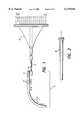
- FIG. 1depicts an electrode array and associated lead for attachment to an implantable cochlear stimulator in accordance with the present invention
- FIG. 2illustrates a side view of the proximal end of the lead of FIG. 1;
- FIG. 3is a more detailed view of the offset portion of the lead/array of FIG. 1;
- FIG. 4shows the electrode array of the present invention having spaced-apart electrode array contacts along the medial side of the array, which electrode array comprises the distal end of the lead/array of FIG. 1;
- FIG. 5shows a detail view of the electrode array contacts of the electrode array of FIG. 4;
- FIG. 5Ais a sectional view of the electrode array taken along the line 5A--5A of FIG. 5;
- FIG. 6shows an alternative embodiment of the electrode array of the present invention wherein bumps are formed in the space between each electrode contact
- FIG. 6Ashows a detail view of the electrode array contacts of the alternative electrode array of FIG. 6;
- FIG. 6Bis a sectional view of the alternative electrode array taken along the line 6B--6B of FIG. 6A;
- FIG. 7Adepicts a preferred manner of making a multi-electrode contact array in accordance with the present invention
- FIG. 7Bshows an enlarged view the "T" strips used in making the electrode contacts of the array of FIG. 7A;
- FIGS. 8A, 8B, 8C and 8Dillustrate one manner in which wires are bonded and routed to each of the "T" strip electrode contacts of FIG. 7B during manufacture of the electrode array;
- FIG. 9depicts a molding die onto which the partially-formed electrode array of FIG. 7A, with wires attached to each of the electrodes as shown in FIGS. 8A-8D, may be mounted in order to form a straight polymer carrier for the electrode array;
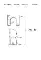
- FIGS. 10 and 11illustrate a perspective and side exploded view, respectively, of an alternative type of molding die onto which the partially-formed electrode array of FIG. 7A, with wires attached to each of the electrodes as shown in FIGS. 8A-8D, may be mounted in order to form a curved polymer carrier for the electrode array;
- FIG. 12is a perspective view of a universal electrode array formed on a flexible carrier made in accordance with the present invention.
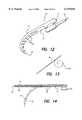
- FIG. 13shows a perspective view of a positioning stylet used with the invention, made from memory wire, and designed to assume a spiral shape, as shown by the phantom lines in FIG. 13, when raised to or near body temperature;
- FIG. 14is a side view of the electrode array of the present invention and illustrates a preferred shape of the electrode array absent the positioning stylet;
- FIG. 15is a schematic representation of a cross-sectional view of the scala tympani duct of the cochlea, illustrating the non-modiolus-hugging position of the electrode array of FIG. 14 when first inserted therein;
- FIG. 16is a schematic representation as in FIG. 15, showing the modiolus-hugging position of the electrode array after insertion of the positioning stylet therein, and after the positioning stylet has assumed its memory spiral shape.
- This positioning styletis made from a memory shape wire that assumes a spiral shape at or near body temperature,
- the electrode arrayalso assumes a spiral shape.
- This spiral shapecauses the electrode array to hug the modiolar wall, thereby positioning the electrode contacts of the electrode array against the modiolar wall, which is the desired goal.
- a flexible positionerof the type described in the referenced '063 patent application with the electrode array of the present invention.
- FIGS. 1-11are generally the same as, and the description thereof generally follows, the description provided in Applicant's parent application, Serial Number 09/247,734, filed Feb. 9, 1999 (Attorney Docket No. AB-034A3), entitled “Cochlear Electrode Array With Electrode Contacts on Medial Side”, previously incorporated herein by reference.
- FIG. 12there is shown a perspective view of a universal electrode array 10 made in accordance with the present invention.
- the array 10includes a flexible carrier body 13 having a channel 11 that passes longitudinally therethrough.
- a multiplicity of spaced-apart electrode contacts 32are formed on the carrier body, each of which is connected to a respective wire 15 that is embedded within the body 13.
- the flexible carrier body 13may be molded from silicone rubber, or any other suitable flexible substance, as is known in the art. It may be molded to assume a relatively straight shape, as shown in FIG. 14, or a slightly curved shape, as shown by the phantom lines in FIG. 14.
- the electrode contacts 32are spaced apart along a medial side 12 of the carrier body 13.
- the flexible carrier 12is adapted to assume a spiral shape after insertion into the scala tympani of the cochlea.
- the medial side 12is that side of the array 10 which is on the inside of the spiral, or inside of the curve of the spiral.
- the channel 11passes longitudinally through the flexible carrier body 13 up to a distal tip 14, where the channel is closed.
- the channel 11has a diameter sufficiently large to allow a positioning stylet 20 to be slidably inserted therein from the proximal end.
- the positioning stylet 20is shown in FIG. 13. It is made from a suitable memory wire, e.g., Nitinol Memory Wire, and has a diameter slightly less than the diameter of the channel 11. In a preferred embodiment, the stylet 20 has a diameter of about 0.1 mm.
- the properties of the wire from which the positioning stylet 20 is madeare selected to obtain shape transformation at or near body temperature, e.g., at or a few degrees below 37° C. (or 98.6° F.).
- the memorized shape of the stylet 20is in the form of a spiral 20A, as shown in the phantom lines of FIG. 13. This spiral shape preferably resembles or matches the average curvature of the cochlear modiolus.
- the electrode array 10is inserted into the scala tympani duct 16 of the cochlea as illustrated in FIG. 15 using conventional electrode insertion techniques.
- FIG. 15is not intended to be anatomically accurate, but rather is just a schematic representation of a cross-sectional view of the spiralling scala tympani duct 16 of a cochlea.
- the modiolus 17i.e., the conical central pillar of the cochlea. It is within the modiolus where the ganglion cells are located that are stimulated by electrical currents flowing from or to the electrode contacts 32 of the array 10.
- the position of the electrode array 10 shown in FIG. 15represents the non-modiolus-hugging position of the electrode array 10 when first inserted into the cochlea. As seen in FIG. 15, the array 10 resides against the outer wall of the duct 16 with the electrode contacts 32 being positioned some distance from the modiolus 17.
- the positioning stylet 20is straightened at a low temperature, i.e., at a temperature below the shape transformation temperature.
- the straightened stylet 20is gradually inserted into the channel 11 of the electrode array 10 until the tip of the stylet wire reaches the distal tip 14 of the array.
- the positioning stylet 20warms to body temperature and recovers its curved shape 20A.
- the positioning stylet 20relocates the electrode array 10 to the preferred modiolus-hugging position shown in FIG. 16.
- the electrode contacts 32are in close proximity to the modiolus 17, and hence in close proximity to the spiral ganglion cells that are to be stimulated.
- the memory-shaped stylet wire 20is permanently inserted into the channel 11 of the electrode array body 13. Before insertion, the stylet wire and electrode array 10 are straightened at a low temperature. Once inserted into the cochlea, the array 10 assumes its spiral shape as the stylet 20 recovers its memory spiral shape.
- in-lineused to describe the electrode contacts, means only that the electrode contacts are spaced apart more or less in alignment with the longitudinal axis of a lead. It does not mean that a perfect, straight alignment with the lead axis must be achieved. For example, electrode contacts that zigzag somewhat with respect to the lead axis would still be considered to be in-line electrodes for purposes of the present invention. Thus, in general, "in-line” means that of two adjacent electrode contacts, one will be more distal than the other. Further, all of the in-line electrode contacts will have an exposed surface which, more or less, lies on the same side--the medial side--of the curved electrode.
- the electrode array 10 of the present inventionmay be best used with an implantable multichannel pulse generator, e.g., an implantable cochlear stimulator (ICS) of the type disclosed in U.S. Pat. No. 5,603,726, incorporated herein by reference, or other suitable stimulator.
- ICSimplantable cochlear stimulator
- ICSimplantable cochlear stimulator
- the electrode array of the present inventionis particularly adapted to bend or flex in one direction, thereby making it suitable for insertion into a curved body cavity, such as the cochlea, and thereafter assuming a curved or spiral shape as guided by the memory shape of the stylet wire 20.
- an important feature of the electrode array of the present inventionis that all of the active electrode contacts of the array are generally positioned along one side, e.g., the medial side (the inside of the curve or bend), of the array.
- the electrode contactswhen inserted into the curved or spiraling cochlea, which may advantageously be either a left or right cochlea, wherein the cells to be stimulated are located within the center modiolar wall, the electrode contacts are positioned proximate the modiolar wall, where they are closest to the cells to be stimulated.
- the electrode array of the present inventionfacilitates stimulation of the desired cells at lower power levels than would otherwise be needed if the electrode contacts were not proximate the modiolar wall.
- the electrode contactshave, in the preferred embodiment, a relatively large exposed electrode surface area that is generally planar or flat having a desired geometric shape, e.g., rectangular, semicircular, or oval.
- a desired geometric shapee.g., rectangular, semicircular, or oval.
- the principles of the inventionmay also be practiced with electrodes that have exposed surface areas that are not flat, e.g., dimpled, or corrugated, or pitted, and that may have an exposed surface area that has irregular geometric shapes.
- the materials from which the electrode array of the invention is made, and the manner of making the electrode arraymay be conventional, as are known in the art.
- FIG. 1A preferred electrode array 30 in accordance with the present invention is shown in FIG. 1.
- the electrode array 30forms the distal end of a lead/array assembly 40 adapted to be connected to an implantable cochlear stimulator (ICS), not shown.
- the lead/array assembly 40includes the electrode array 30, a fantail proximal connector 42, and a lead body 44 connecting the array 30 to the proximal connector 42.
- the ICSis typically housed within a ceramic or other case, such as is disclosed in U.S. Pat. No. 4,991,152, incorporated herein by reference.
- the casehas an array of feedthrough terminals corresponding to its multiple channels.
- a preferred ICShas eight channels, with each channel having two feedthrough terminals connected thereto.
- Such terminalsare typically labeled as M1 and L1 (for medial and lateral) for the first channel, M2 and L2 for the second channel, and so on, up to and including M8 and L8 for the eighth channel.
- each feedthrough terminalis spaced across a header of the case. Inside the case, each feedthrough terminal is connected to appropriate electronic circuitry for the corresponding channel, as taught in the previously-referenced '726 patent. On the outside of the case, each feedthrough terminal is connected to a corresponding wire conductor within the lead/array assembly 40.
- wire conductorsare identified in FIG. 1 by the numbers 1' through 16'.
- the wire conductors 1'-16'are of necessity spread out at the point where they connect to the feedthrough terminals of the header.
- the proximal end of the lead/assembly 40includes the fantail connector 42 that funnels the spread conductors 1'-16' at the point they connect to the feedthrough terminals down to the lead body 44.
- a side view of the fantail connector 42is shown in FIG. 2.
- the manner of forming the fantail connector 42, and connecting it to the feedthrough terminalsmay be conventual, and does not form part of the present invention. Rather, the present invention is directed to the electrode array 30 at the distal end of the lead/assembly 40. It should be emphasized that the electrode array 30 is not limited to use with a proximal fantail connector 42 and the type of ICS disclosed in the '726 patent. Rather, the electrode array 30 may be used with any type of proximal connector that interfaces with an appropriate pulse generator.
- the electrode array 30may be curved an appropriate amount.
- a multiplicity of in-line electrode contacts 32are spaced apart so as to lie on the medial side (inside of the curve) of the array. Sixteen such electrode contacts 32 are used in a preferred embodiment of the array 30. These electrode contacts are respectively connected to the wire conductors 1'-16' within the lead.
- the most distal electrode contactfor example, may be connected to wire conductor 1' within the lead 44, which in turn is connected to the feedthrough terminal L1 at the pulse generator.
- the second-most distal electrode contactmay similarly be connected to wire conductor 2' within the lead 44, and may be connected to the feedthrough terminal M1 at the pulse generator.
- the two-most distal electrode connectors 32 on the arraymay be connected to the first channel of the implantable pulse generator.
- the two most proximal electrode contacts on the array 30may be connected to wire conductors 15' and 16' within the lead 44, and may be connected, e.g., to feedthrough terminals L8 and M8, corresponding to the eighth channel, of the implantable pulse generator.
- the other electrode contacts 32 included within the array 30may be similarly connected to a corresponding channel within the pulse generator.
- the preferred electrode array 30also includes three reference electrode contacts 34, identified in FIG. 1 by the electrode numbers 17', 18' and 19'.
- Such reference contacts 34are not connected to any wire conductors within the lead 44, and for this reason are sometimes referred to as "dummy reference contacts". Rather, each of these reference contacts 34 may provide a reference indicator or marker to the physician inserting the electrode array relative to the depth of insertion.
- the lead/array assembly 40further includes an offset portion 46 that effectively marks the end of the lead 44 and the beginning of the electrode array 30.
- offset portion 46facilitates insertion of the electrode array 30 into the scala tympani duct of the cochlea.
- the insertion processmay be conventional, and is aided by a special tool of the type disclosed in the '493 patent, previously referenced.
- the offset portion 46separates the body of the lead 44 from the body of the array 30 by an offset distance L4.
- this distance L4in the preferred embodiment, is about 1.3 mm.
- the diameter of the lead 44is a distance L5, while the diameter of the electrode array is a distance L6. In the preferred embodiment, both L5 and L6 are about 0.8 mm.
- the length L9 of the offset portion 46is approximately 1.6 mm, allowing the wire conductors 1'-16' within the electrode array 30 to transition to the lead body 44 without too sharp of a bend. It is to be understood that these dimensions, as well as other dimensions presented herein, are only exemplary of one embodiment, and are not meant to be limiting.
- the electrode arrayis molded over a silicone rubber tube 43, which tube 43 provides the channel 11 through which the positioning stylet 20 is inserted.
- the outer diameter of the tube 43may be, e.g., approximately 0.64 mm.
- the material from which the lead/array 40, including the electrode array 30, is mademay be any suitable biocompatible material commonly used with implantable leads and other implantable components as is known in the art.
- a suitable materialfor example, is a type of silicone polymer or rubber known as LSR-70 or LSR-25.
- LSR-70 and LSR-25are well known in the art, and LSR-70 and LSR-25 may be obtained commercially from numerous sources,.
- LSR-70is formed into a desired shape by injecting or otherwise inserting it into a mold while in a liquid state and allowing it to cure in the mold at a specified temperature for a specified time period. For example, LSR-70 may cure at a temperature of 140 degrees C. for about 15 minutes.
- LSR-25may likewise be formed into a desired shape using a similar molding process, or it may be applied through a suitable applicator, e.g, a syringe, to a desired area and then formed into a desired shape.
- LSR-25is essentially the same as LSR-70 except that when it cures it is significantly softer, i.e., more pliable. Both LSR-70 and LSR-25 readily adhere to the tubing 43 so that when cured they become integral therewith.
- the distance from the proximal end of the electrode array 30 to the proximal edge of electrode contact 16'is a distance L3.
- the distance L3is about 10.5 mm.
- the electrode array 30includes electrode array contacts 32 equally-spaced along a medial side of a flexible carrier 36.
- the flexible carrier 36is made from LSR-70, and is molded around an assembly of electrode contacts 32 and interconnecting wires as described below in conjunction with FIGS. 7A-11.
- the electrode array 30has an overall length L7. Such length L7 is most easily measured when the array 30 is straightened, as shown by the phantom lines in FIG. 3. In the preferred embodiment, L7 has a value of approximately 25 mm.
- the electrode array 30could be formed to assume any desired shape, in the preferred embodiment it is formed to include a natural curve having a radius of curvature r2, with the electrode contacts 32 being positioned along the inside of the curve.
- the radius of curative r2may have a value of approximately 9.0 mm.
- a soft tip 37having a depth of distance L8, is typically formed from LSR-25 at the very distal tip of the electrode array 30.
- L8has a value of approximately 0.3 mm.
- the reference marker contacts 34are spaced from the active electrode 16' a distance L11, with a spacing between the reference marker electrodes of L10.
- the distance L11is about 3.0 mm
- the distance L10is about 1.0 mm.
- each exposed electrode contact surface areacomprises a generally rectangular-shaped area having a length L1 and a width W1. Other shapes could also be used.
- the rectangular areais roughly a square, with L1 and W1 each having a value of approximately 0.4 mm ⁇ 10%, thereby providing an exposed electrode surface area of approximately 0.16 mm 2 .
- the spacing between corresponding points of adjacent electrode contact areas 32is a distance L2.
- L2has a nominal value of approximately 0.9 mm ⁇ 0.1 mm.
- the electrode contact areascomprise an exposed surface of an electrode contact 32 that is formed from folded strips 210 and 220 of a biocompatible metal, such as platinum, as described more fully below in conjunction with FIGS. 7A-8D.
- Such electrode contactsare embedded within the molded carrier 36 as illustrated in the sectional view of FIG. 5A, which is taken along the lines 5A-5A of FIG. 5.
- the carrier 36is formed to have a cross-sectional area that is generally rectangular, having dimensions of X by Y mm, where the values of X and Y vary as a function of where along the length of the carrier the cross section is viewed.
- X and Yare both about 0.8 mm.
- X and Yare both about 0.6 mm.
- the carrier 36is tapered along its length so that it has a smaller cross section at its distal tip than it does at its proximal end.
- the sectional shapehas rounded corners on the side opposite the medial side.
- the medial sideis the side where the electrode contacts 32 are located.
- the rounded cornershave a radius of curvature r1 that is approximately 0.3 mm in one representative embodiment.
- the electrode contacts 32have a general cross sectional shape, as seen in FIG. 5A, and as will be more evident from the description below of FIGS. 7A-8D below, that resembles a triangle or a "U".
- the base of this triangular-shaped (or " ⁇ -shaped") or U-shaped electrodeforms the exposed electrode contact area along the medial side of the electrode array, e.g., as seen in FIG. 5.
- the upward sloping legs 220 of this ⁇ -shaped or U-shaped electrodeextend into the body of the carrier, e.g., as anchors, and thus become embedded (non-exposed) portions of the electrodes.
- the legs 220extend into the body of the carrier, in some fashion, so that the electrode is firmly anchored in its desired position along the length of the array.
- the lumen 11passes through the central portion of the body of the carrier.
- the legs 220may be completely folded over so as to lie almost flat on top of the exposed surface area, as shown generally in parent application (Ser. No. 09/140,034 now U.S. Pat. No. 6,038,484).
- the legs 220may extend more or less straight into the body of the carrier, forming a generally block "U" cross-sectional shape, as shown in FIG. 5A.
- the legs 220may slope so as to generally form a triangle, or ⁇ -shape, as illustrated, e.g., in FIG. 6B.
- Wire bundles 202 and 203pass through the corners of the ⁇ -shaped, U-shaped (or other-shaped) electrodes and become embedded within the molded carrier 36 when formed. As explained in more detail below, at least one wire from at least one of these wire bundles makes electrical contact with each active electrode. The wires that do not make electrical contact with an electrode contact are nonetheless engaged by or supported by the embedded portion of the electrode as they pass through the ⁇ or U (or other) shape. Such engagement helps support and position the wire bundles prior to molding the carrier over them.
- the location of the wire bundles immediately behind and along opposing edges of the exposed surface area of the electrodeshelps add additional stiffness to the electrode array, once formed, in the lateral direction, as explained below, thereby making it more difficult to bend or twist the array in the lateral direction.
- the arrayremains relatively easy to bend in the medial direction.
- the medial directionis the direction of curvature defined by the radius r2 (FIGS. 4 and 6).
- FIGS. 6, 6A and 6BAn alternative embodiment an electrode array 30' made in accordance with the present invention is shown in FIGS. 6, 6A and 6B.
- This alternative electrode array 30'is the same as the array 30 illustrated in FIGS. 4, 5 and 5A with the exception that a series of small non-conductive bumps, or humps 70, are formed between the electrode contact areas 32.
- these humps 70have a height H1 of about 0.13 mm, and as seen best in FIG. 6A, have a width W2 of about 0.25 mm.
- the humps 70extend out from the medial surface of the electrode array.
- the humps 70are made from a soft silicone rubber, or equivalent substance, such as LSR-25.
- the small bumps 70When inserted into the cochlea, the small bumps 70 serve as non-irritating stand-offs, or spacers, that allow the electrode contacts 32 to be positioned near the modiolus wall, but prevent the electrode contacts 32 from actually touching the modiolus wall.
- the humps 70further serve as dielectric insulators that help steer the stimulating electrical current, flowing to or from the electrode contacts, in the desired direction, from or towards the cells located in the modiolus wall, as taught, e.g., in the previously referenced copending U.S. patent application Ser. No. 09/137,033. Except for the presence of the humps 70, FIGS. 6, 6A and 6B correspond to FIGS. 4, 5 and 5A.
- the electrode arrayis easy and relatively inexpensive to manufacture.
- a preferred method of making the electrode array 30 or 30'is illustrated, for example, in FIGS. 7A through 11. It is to be emphasized that the method depicted in these figures of making the electrode array is not the only way an electrode array 30 or 30' could be made. However, it represents an easy and inexpensive (and thus a preferred) way to make the electrode array.
- Electrodes and connectorsare based on the principle of molding a contact or array of contacts, usually made from biocompatible metal, into a polymer carrier like silicone or polyurethane rubber.
- the electrode contactsare usually required to be located in a controlled position in reference to the surface of the carrier, with specified surface areas to be fully exposed to the stimulated or interconnection area.
- making such electrodes or connectorsbecomes extremely difficult, especially when the contacts are very small and/or a large number of contacts are required, e.g., as is the case with a cochlea electrode.
- One of the main problems encountered in the fabrication of such electrodes or connectorsis to find a reliable method of holding the system of contacts in the desired and stable position during the process of welding the connecting wires and molding the polymer carrier.
- a further problemrelates to maintaining a controlled surface of the contacts that are to remain exposed, i.e., to ensure that the contacts are not covered by the polymer when the carrier is molded.
- the preferred methods of making the electrode array 30 or 30' described below in connection with FIGS. 7A through FIG. 11are based on the principle of attaching (by the process of resistance welding) electrode contacts made from precious, biocompatible material (such as platinum or its alloys) to a foil carrier made from a non-toxic but chemically-active metal, such as iron (Fe).
- Resistance weldingadvantageously provides a secure attachment of the electrode material to the foil carrier without causing a deep fusion of the two materials being attached.
- the resulting shallow fusion contactallows clean exposed electrode surface areas to be formed when the foil carrier is eventually chemically etched away, as explained below.
- Other types of attachment that result in shallow fusion of the electrode material and the foil carrier sheet materialmay also be used in lieu of resistance welding.
- the electrode contactsremain in a desired and stable position allowing easy connecting of the wiring system and subsequent molding of the polymer carrier.
- the metal foil carrieris chemically etched away using a mixture of diluted acids, such as HNO 3 and HCl.
- the precious metal contacts and polymerare immune to the acid and remain in their intact, unaltered shape, and thereby provide the desired electrode array structure.
- an array of contacts 200are resistance welded onto an iron carrier 100 so as to assume a desired in-line spaced-apart relationship, as shown in FIG. 7A.
- Each contact 200consists of two pieces of platinum foil 210 and 220, connected together and joined to the carrier 100 by a shallow-fusion spot weld 230, as shown in FIG. 7B.
- the width of the strip 210is approximately W1
- the width of the strip 220is approximately L1.
- a wiring systemis connected to each of the electrode contacts 200. This is accomplished as shown in FIGS. 8A, 8B, 8C and 8D.
- an insulated wire 202'is laid on top of the electrode foil piece 220 (the cross bar of the "T").
- the leg of the "T” of the foil piece 210is then folded over to hold the end of the wire while the wire is welded in position (FIG. 8B).
- the welding processpreferably a resistance weld, burns away any insulation from the tip while making a secure mechanical and electrical connection between the wire and the electrode contact 200.
- the resultis an electrode contact 200 having a wire 202' securely attached thereto (FIG. 8C).
- wiresmay pass over the foil piece 210, lying more or less parallel to the wire 202' so as to form a bundle of wires 202.
- a similar bundlemay be formed on the other side of the folded foil piece 210, thereby forming another wire bundle 203.
- the ends of the foil piece 220are then folded upwards to form, in a preferred embodiment, a triangle, or ⁇ shape (as seen in a side view), as shown in FIG. 8D.
- At least one wire from one of the bundles 202 or 203is attached to the electrode contacts 2-16 in the manner described above.
- a wire from wire bundle 202will connect to electrode contact 16
- a wire from bundle 203will connect to electrode contact 15, and so on, with adjacent in-line electrode contacts being connected to wires from alternating wire bundles.
- At least two wires, one from each bundle 202 and 203remain for connection to the most distal electrode contact 1. In this fashion, at least seventeen wires are used to make electrical connection with sixteen electrode contacts.
- the wire bundle 202may contain 9 wires, and the wire bundle 203 may contain 8 wires, for the sixteen-electrode array 30 or 30' described herein.
- the number of electrodescan be n and the number of wires can be at least n+1, where n is an integer of at least 8.
- the wire bundles 202 and 203pass through the dummy electrode contacts, or reference marker contacts 34 (FIG. 1, 6), without making electrical contact therewith.
- the reference marker contacts 34are not shown in FIG. 8A.
- each electrode contacte.g., as seen in the sectional view of FIG. 5A or 6B, and hence on each lateral side of the electrode array, helps add lateral stability to the array. This is true even when the wire "bundle" only contains one wire.
- the wire bundleshelp add stiffness to the electrode array in the lateral direction, but do not materially affect the ability of the array to flex or bend in the medial direction.
- the foil carrier 100may be placed on a molding die 300 as shown in FIG. 9.
- the die 300has alignment pegs 310 adapted to align with corresponding alignment holes 110 in the foil carrier 100.
- the die 300further has a cavity or channel 320 formed therein into which the silicone tube 43, with channel 11 therethrough, may be positioned and the required amount of material, e.g., LSR-70, needed to form the polymer carrier 36 (FIGS. 4, 6) is injected around the tube 43.
- the LSR-70is then cured in conventional manner.
- This cavity or channel 320may be shaped or formed as desired.
- a curved die 301is preferably used as shown in FIGS. 10 and 11.
- Such die 301includes a curved surface 303 on a holding block 304 on which the foil carrier 100 may be placed.
- the block 304has alignment pegs 311 adapted to align with corresponding alignment holes 110 in the foil carrier 100.
- the foil carrier 100is placed on the block 304 and bent over the curved surface 303.
- the die 301is then placed over the block 304, with the foil carrier 100 sandwiched therebetween.
- a channel or cavity 321is formed in the die 301 having the desired shape and characteristics of the carrier that is to be formed through the molding process.
- FIG. 10comprises a perspective view of the die 301 and block 304
- FIG. 11comprises a side or profile view of the die 301 and block 304
- the arraycan be molded or formed to assume a curved shape. Such curved shape may be preferred in some instances.
- the electrode arraymay be formed to assume a natural curved shape, a slightly curved shape, or to be straight.
- the foil carrier with the electrode array assembly(which is now molded inside of the polymer) is removed from the channel of the die 300 or 301/304 and placed in a mixture of diluted acids.
- the mixture of diluted acidsdissolves the foil carrier 100, thereby exposing a clean surface of the electrode contacts 200. After washing to remove any residue of acids and Fe salts, the main electrode array structure is completed.
- the electrode arrayAs the electrode array is inserted deeper into the cochlea, the electrode array does not easily twist, or bend laterally, which twisting or bending could move the electrode contacts away from the modiolus wall. This is because the electrode array is inherently stiffer in the lateral direction than in the medial direction due primarily to the presence of the wire bundles and folded/bent electrode contacts which provide an added degree of stiffness in the lateral direction.
- the electrode contacts 32may be viewed as rigid rectangular plates, hinged together by the flexible carrier material between each plate.
- sixteen such platesare hinged together in a long chain, each plate in the chain being connected to an adjacent plate in the chain by way of a hinged connection.
- Such chain of "hinged plates”may readily pivot about their respective hinged connections, thus easily and readily allowing the chain of hinged plates to bend in the medial direction.
- bending in the lateral directionassuming a perfect hinged connection, is virtually impossible.
- Even assuming a less-than-perfect hinged connectionbending in the lateral direction is still made difficult.
- fixed-length wire bundlesare embedded in the carrier on opposite lateral sides of the array.
- These "matched" (of equal length) wire bundlestend to make lateral bending or flexing more difficult because such lateral flexing or bending would typically require that one of the wire bundles increase in length, as the other decreases in length, as a lateral bend is made.
- the electrode contacts of the electrode array disclosed hereinremain facing and closest to the modiolus wall, stimulation of the cells embedded within the modiolus wall may occur at lower energy settings than would be required if the electrode contacts were not facing and closest to the modiolus wall.
- use of the present electrode arrayallows desired stimulation to be achieved at lower power levels.
- Lower power levelsin turn, mean that the overall cochlear stimulation system may operate on less power, which usually means a longer interval between battery replacement.
- the present inventionprovides an electrode array that is easy to manufacture and which provides enhanced performance when used.
- Such electrode arrayprovides an array of spaced-apart electrodes along the medial side of the array.
- a positioning styletis inserted into a channel of the array, which stylet assumes a curved spiraling shape upon warming to body temperature, and causes the electrode contacts to face and hug the modiolus wall.
- the composition and makeup of the electrode arraymakes it easier to bend in the medial direction than in a sideways or lateral direction.
- the electrode contactsremain on the medial side of the electrode, hugging the modiolus wall, after the electrode is inserted into the cochlea.
Landscapes
- Health & Medical Sciences (AREA)
- Otolaryngology (AREA)
- Cardiology (AREA)
- Heart & Thoracic Surgery (AREA)
- Engineering & Computer Science (AREA)
- Biomedical Technology (AREA)
- Nuclear Medicine, Radiotherapy & Molecular Imaging (AREA)
- Radiology & Medical Imaging (AREA)
- Life Sciences & Earth Sciences (AREA)
- Animal Behavior & Ethology (AREA)
- General Health & Medical Sciences (AREA)
- Public Health (AREA)
- Veterinary Medicine (AREA)
- Prostheses (AREA)
- Electrotherapy Devices (AREA)
Abstract
Description
Claims (14)
Priority Applications (1)
| Application Number | Priority Date | Filing Date | Title |
|---|---|---|---|
| US09/259,199US6119044A (en) | 1997-06-02 | 1999-03-01 | Cochlear electrode array with positioning stylet |
Applications Claiming Priority (5)
| Application Number | Priority Date | Filing Date | Title |
|---|---|---|---|
| US8765597P | 1997-06-02 | 1997-06-02 | |
| US7967698P | 1998-03-27 | 1998-03-27 | |
| US09/140,034US6038484A (en) | 1997-09-02 | 1998-08-26 | Cochlear electrode with modiolar-hugging system including a flexible positioner |
| US09/247,734US6129753A (en) | 1998-03-27 | 1999-02-09 | Cochlear electrode array with electrode contacts on medial side |
| US09/259,199US6119044A (en) | 1997-06-02 | 1999-03-01 | Cochlear electrode array with positioning stylet |
Related Parent Applications (1)
| Application Number | Title | Priority Date | Filing Date |
|---|---|---|---|
| US09/247,734Continuation-In-PartUS6129753A (en) | 1997-06-02 | 1999-02-09 | Cochlear electrode array with electrode contacts on medial side |
Publications (1)
| Publication Number | Publication Date |
|---|---|
| US6119044Atrue US6119044A (en) | 2000-09-12 |
Family
ID=27491496
Family Applications (1)
| Application Number | Title | Priority Date | Filing Date |
|---|---|---|---|
| US09/259,199Expired - Fee RelatedUS6119044A (en) | 1997-06-02 | 1999-03-01 | Cochlear electrode array with positioning stylet |
Country Status (1)
| Country | Link |
|---|---|
| US (1) | US6119044A (en) |
Cited By (127)
| Publication number | Priority date | Publication date | Assignee | Title |
|---|---|---|---|---|
| WO2002032498A1 (en) | 2000-10-17 | 2002-04-25 | Cochlear Limited | Insertion tool for a cochlear implant electrode array |
| WO2002074211A1 (en)* | 2001-03-19 | 2002-09-26 | Cochlear Limited | Insertion tool system for an electrode array |
| WO2002078575A1 (en)* | 2001-03-29 | 2002-10-10 | Cochlear Limited | Laminated electrode for a cochlear implant |
| US6498954B1 (en) | 2000-01-14 | 2002-12-24 | Advanced Bionics Corporation | Apex to base cochlear implant electrode |
| US20030045921A1 (en)* | 2000-10-11 | 2003-03-06 | Fysh Dadd | Double stylet insertion tool for a cochlear implant electrode array |
| US20030097165A1 (en)* | 2001-11-16 | 2003-05-22 | The Regents Of The University Of California. | Flexible electrode array for artificial vision |
| US20030181967A1 (en)* | 2000-10-04 | 2003-09-25 | Fysh Dadd | Combination stylet and straightening coating for a cochlear implant electrode array |
| WO2003090848A1 (en)* | 2002-04-23 | 2003-11-06 | Cochlear Limited | Electrode array for a cochlear implant having one or more adjustable electrodes |
| WO2004004413A1 (en)* | 2002-06-28 | 2004-01-08 | Cochlear Limited | Cochlear implant electrode array |
| US20040116995A1 (en)* | 2001-03-12 | 2004-06-17 | Fysh Dadd | Curved cochlear implant electrode array |
| US20040122501A1 (en)* | 2000-10-04 | 2004-06-24 | Fysh Dadd | Cochlear implant electrode array |
| US20040127968A1 (en)* | 2002-09-19 | 2004-07-01 | Kuzma Janusz A. | Cochlear implant electrode and method of making same |
| US20040172102A1 (en)* | 2000-04-13 | 2004-09-02 | Cochlear Limited | At least partially implantable system for rehabilitation of a hearing disorder |
| US20040220651A1 (en)* | 2002-09-19 | 2004-11-04 | Kuzma Janusz A | Cochlear implant electrode and method of making same |
| US20040236390A1 (en)* | 2003-04-16 | 2004-11-25 | Fysh Dadd | Cochlear electrode array |
| US20040243212A1 (en)* | 2003-04-17 | 2004-12-02 | Fysh Dadd | Electrode array with bendable tip |
| US20050015133A1 (en)* | 2001-06-29 | 2005-01-20 | Ibrahim Ibrahim Hanna | Multi-electrode cochlear implant system with distributed electronics |
| KR100492515B1 (en)* | 2002-04-29 | 2005-06-03 | 주식회사 뉴로바이오시스 | Cochlear implant electrode and its fabricating method |
| US20050137646A1 (en)* | 2003-12-22 | 2005-06-23 | Scimed Life Systems, Inc. | Method of intravascularly delivering stimulation leads into brain |
| US20050187589A1 (en)* | 2004-02-20 | 2005-08-25 | Scimed Life Systems, Inc. | Method of stimulating/sensing brain with combination of intravascularly and non-vascularly delivered leads |
| US20050203602A1 (en)* | 2004-03-12 | 2005-09-15 | Scimed Life Systems, Inc. | Collapsible/expandable electrode leads |
| US20050203600A1 (en)* | 2004-03-12 | 2005-09-15 | Scimed Life Systems, Inc. | Collapsible/expandable tubular electrode leads |
| US6968238B1 (en) | 1998-08-26 | 2005-11-22 | Kuzma Janusz A | Method for inserting cochlear electrode and insertion tool for use therewith |
| US20050261748A1 (en)* | 2004-05-10 | 2005-11-24 | Cochlear Limited | Cochlear implant fitting |
| US20050267558A1 (en)* | 2004-05-26 | 2005-12-01 | Frijns Johannes H | Cochlear lead |
| US20060085055A1 (en)* | 2004-09-07 | 2006-04-20 | Cochlear Limited | Cochlear electrode with precurved and straight sections |
| US20060184143A1 (en)* | 2001-10-24 | 2006-08-17 | Med-El Elektromedizinische Geraete Gmbh | Implantable fluid delivery apparatuses and implantable electrode |
| US20060241723A1 (en)* | 2002-02-22 | 2006-10-26 | Cochlear Limited | Insertion device for an electrode array |
| US20060287690A1 (en)* | 2004-05-10 | 2006-12-21 | Cochlear Limited | Simultaneous delivery of electrical and acoustical stimulation in a hearing prosthesis |
| US20070055272A1 (en)* | 2005-08-16 | 2007-03-08 | Laurent Schaller | Spinal Tissue Distraction Devices |
| US20070088335A1 (en)* | 2001-10-24 | 2007-04-19 | Med-El Elektromedizinische Geraete Gmbh | Implantable neuro-stimulation electrode with fluid reservoir |
| US7231260B2 (en) | 2004-05-06 | 2007-06-12 | Boston Scientific Scimed, Inc. | Intravascular self-anchoring electrode body with arcuate springs, spring loops, or arms |
| AU2002238300B2 (en)* | 2001-03-19 | 2007-07-12 | Cochlear Limited | Insertion tool system for an electrode array |
| US20070162098A1 (en)* | 2005-12-08 | 2007-07-12 | Cochlear Limited | Prosthetic hearing implant electrode assembly having optimal length for atraumatic implantation |
| US20070213799A1 (en)* | 2006-03-09 | 2007-09-13 | Claude Jolly | Cochlear Implant Electrode Configuration for Drug Eluting |
| US7286879B2 (en) | 2004-07-16 | 2007-10-23 | Boston Scientific Scimed, Inc. | Method of stimulating fastigium nucleus to treat neurological disorders |
| US20080119910A1 (en)* | 2004-09-07 | 2008-05-22 | Cochlear Limited | Multiple channel-electrode mapping |
| US20080154272A1 (en)* | 2005-08-16 | 2008-06-26 | Laurent Schaller | Apparatus and Method for Treating Bone |
| US20080234687A1 (en)* | 2005-08-16 | 2008-09-25 | Laurent Schaller | Devices for treating the spine |
| US20080234793A1 (en)* | 2007-03-20 | 2008-09-25 | Cochlear Limited | Securing an implanted medical device in a patient |
| US7451000B2 (en) | 2000-11-29 | 2008-11-11 | Cochlear Limited | Pre-curved cochlear implant electrode array |
| WO2008103781A3 (en)* | 2007-02-21 | 2008-11-20 | Benvenue Medical Inc | Devices for treating the spine |
| US20090048580A1 (en)* | 2007-08-13 | 2009-02-19 | Cochlear Limited | Independently-manufactured drug delivery module and corresponding receptacle |
| US20090062896A1 (en)* | 2007-08-29 | 2009-03-05 | Overstreet Edward H | Minimizing Trauma During and After Insertion of a Cochlear Lead |
| US20090076521A1 (en)* | 2007-09-18 | 2009-03-19 | Morten Hansen | Apparatus and method for inserting implants into the body |
| US20090076581A1 (en)* | 2000-11-14 | 2009-03-19 | Cochlear Limited | Implantatable component having an accessible lumen and a drug release capsule for introduction into same |
| US20090132042A1 (en)* | 2007-10-17 | 2009-05-21 | Hetke Jamille F | Implantable device including a resorbable carrier |
| WO2009065127A1 (en)* | 2007-11-16 | 2009-05-22 | Cochlear Americas | Electrode array and method of forming an electrode array |
| US20090182403A1 (en)* | 2008-01-10 | 2009-07-16 | Arkady Glukhovsky | Methods and apparatus for implanting electronic implants within the body |
| US7590454B2 (en) | 2004-03-12 | 2009-09-15 | Boston Scientific Neuromodulation Corporation | Modular stimulation lead network |
| US20090240099A1 (en)* | 2008-02-29 | 2009-09-24 | Otologics, Llc | Bi-modal cochlea stimulation |
| US20090254163A1 (en)* | 2007-03-20 | 2009-10-08 | Cochlear Limited | Securing an implanted medical device in a patient |
| US20090287277A1 (en)* | 2008-05-19 | 2009-11-19 | Otologics, Llc | Implantable neurostimulation electrode interface |
| US20090292237A1 (en)* | 2007-08-29 | 2009-11-26 | Advanced Bionics, Llc | Modular Drug Delivery System for Minimizing Trauma During and After Insertion of a Cochlear Lead |
| US20090292329A1 (en)* | 2000-11-14 | 2009-11-26 | Cochlear Limited | Apparatus for delivery of pharmaceuticals to the cochlea |
| US20100069997A1 (en)* | 2008-09-16 | 2010-03-18 | Otologics, Llc | Neurostimulation apparatus |
| US20100106134A1 (en)* | 2008-10-15 | 2010-04-29 | Med-El Elektromedizinische Geraete Gmbh | Inner Ear Drug Delivery Device and Method |
| US20100114288A1 (en)* | 2008-10-31 | 2010-05-06 | Advanced Bionics, Llc | Cochlear electrode insertion |
| US20100121256A1 (en)* | 2008-11-10 | 2010-05-13 | Med-El Elektromedizinische Geraete Gmbh | Implantable and Refillable Drug Delivery Reservoir |
| US20100268313A1 (en)* | 2009-04-16 | 2010-10-21 | Otologics, Llc | Reference electrode apparatus and method for neurostimulation implants |
| US20100305676A1 (en)* | 2007-11-16 | 2010-12-02 | Fysh Dadd | Cochlear implant electrode assembly |
| US20100318167A1 (en)* | 2009-04-17 | 2010-12-16 | Otologics, Llc | Neurostimulation electrode array and method of manufacture |
| US20100326723A1 (en)* | 2007-07-17 | 2010-12-30 | Cochlear Limited | Electrically insulative structure having holes for feedthroughs |
| US20110022145A1 (en)* | 2009-07-21 | 2011-01-27 | Timothy Beerling | Integrated wire carrier for electrode array |
| US20110016710A1 (en)* | 2007-12-21 | 2011-01-27 | Fysh Dadd | Electrode array assembly |
| US7937160B2 (en) | 2004-12-10 | 2011-05-03 | Boston Scientific Neuromodulation Corporation | Methods for delivering cortical electrode leads into patient's head |
| US20110106101A1 (en)* | 2009-10-30 | 2011-05-05 | Advanced Bionics, Llc | Steerable Stylet |
| US20110160822A1 (en)* | 2009-12-30 | 2011-06-30 | Jackson Timothy R | Implantable lead electrode with asymetrically distributed current density and methods for imparting current density directionality in lead electrodes |
| US20110156306A1 (en)* | 2009-12-30 | 2011-06-30 | Morris Kimberly A | Implantable leads with a unitary silicone component |
| US20110160821A1 (en)* | 2009-12-30 | 2011-06-30 | Jackson Timothy R | Electrode surface modification for imparting current density directionality in lead electrodes |
| US20110160823A1 (en)* | 2009-12-30 | 2011-06-30 | Andrew De Kock | Implantable leads with a low coefficient of friction material |
| US8060207B2 (en) | 2003-12-22 | 2011-11-15 | Boston Scientific Scimed, Inc. | Method of intravascularly delivering stimulation leads into direct contact with tissue |
| CN102274098A (en)* | 2011-05-16 | 2011-12-14 | 上海华聆人工耳医疗科技有限公司 | Prebending-type artificial cochlear electrode |
| WO2012082842A1 (en)* | 2010-12-15 | 2012-06-21 | Med-El Elektromedizinische Geraete Gmbh | Elongate electrode for a cochlear implant |
| US8452421B2 (en) | 2009-07-08 | 2013-05-28 | Advanced Bionics, Llc | Lead insertion tools |
| US8473075B2 (en) | 2010-06-25 | 2013-06-25 | Advanced Bionics | Cochlear implant system with removable stylet |
| US8535327B2 (en) | 2009-03-17 | 2013-09-17 | Benvenue Medical, Inc. | Delivery apparatus for use with implantable medical devices |
| US8617097B2 (en) | 2010-05-24 | 2013-12-31 | Cochlear Limited | Drug-delivery accessory for an implantable medical device |
| US8753352B2 (en) | 2010-06-25 | 2014-06-17 | Advanced Bionics Ag | Tools, systems, and methods for inserting a pre-curved electrode array portion of a lead into a bodily orifice |
| US8753353B2 (en) | 2010-06-25 | 2014-06-17 | Advanced Bionics Ag | Tools, systems, and methods for inserting an electrode array portion of a lead into a bodily orifice |
| US8774944B2 (en) | 2010-06-25 | 2014-07-08 | Advanced Bionics Ag | Tools, systems, and methods for inserting an electrode array portion of a lead into a bodily orifice |
| US8880193B1 (en) | 2009-05-22 | 2014-11-04 | Advanced Bionics, Llc | Cochlear electrode array |
| EP2823855A1 (en)* | 2013-07-10 | 2015-01-14 | cerbomed GmbH | Stimulation device |
| US20150018911A1 (en)* | 2013-07-02 | 2015-01-15 | Greatbatch Ltd. | Apparatus, system, and method for minimized energy in peripheral field stimulation |
| US9037267B2 (en) | 2010-05-27 | 2015-05-19 | Advanced Bionics Llc | Cochlear lead |
| US9033869B2 (en) | 2010-05-27 | 2015-05-19 | Advanced Bionics, Llc | Cochlear lead |
| US9188347B1 (en)* | 2012-09-01 | 2015-11-17 | Home Energy Technologies, Inc. | Remote distance transporting and integrating heat ejection connected to central heating ductwork (auxiliary heat ejectors) |
| US9314252B2 (en) | 2011-06-24 | 2016-04-19 | Benvenue Medical, Inc. | Devices and methods for treating bone tissue |
| US9345397B2 (en) | 2010-09-21 | 2016-05-24 | The Johns Hopkins University | Optical sensing system for cochlear implant surgery |
| US9474546B1 (en) | 2008-04-18 | 2016-10-25 | Advanced Bionics Ag | Pre-curved electrode array insertion tools |
| CN106794345A (en)* | 2014-10-06 | 2017-05-31 | Med-El电气医疗器械有限公司 | For the improved contact conductor of cochlear implant |
| US9744346B2 (en) | 2014-07-17 | 2017-08-29 | Cochlear Limited | Implantable stimulating assembly arrangements |
| US9788963B2 (en) | 2003-02-14 | 2017-10-17 | DePuy Synthes Products, Inc. | In-situ formed intervertebral fusion device and method |
| US10516953B2 (en) | 2009-05-29 | 2019-12-24 | Cochlear Limited | Implantable auditory stimulation system and method with offset implanted microphones |
| US10888433B2 (en) | 2016-12-14 | 2021-01-12 | DePuy Synthes Products, Inc. | Intervertebral implant inserter and related methods |
| US10940016B2 (en) | 2017-07-05 | 2021-03-09 | Medos International Sarl | Expandable intervertebral fusion cage |
| US10966840B2 (en) | 2010-06-24 | 2021-04-06 | DePuy Synthes Products, Inc. | Enhanced cage insertion assembly |
| US10973652B2 (en) | 2007-06-26 | 2021-04-13 | DePuy Synthes Products, Inc. | Highly lordosed fusion cage |
| US11071869B2 (en) | 2016-02-24 | 2021-07-27 | Cochlear Limited | Implantable device having removable portion |
| US20210236808A1 (en)* | 2019-10-10 | 2021-08-05 | Advanced Bionics Ag | Apparatus and methods for making cochlear implant electrode arrays |
| US11103704B2 (en)* | 2016-11-08 | 2021-08-31 | Advanced Bionics Ag | Electrode arrays and cochlear implants including the same |
| US20210322772A1 (en)* | 2020-04-21 | 2021-10-21 | Cochlear Limited | Sensory substitution |
| US20210346697A1 (en)* | 2016-08-11 | 2021-11-11 | Advanced Bionics Ag | Cochlear implants including electrode arrays and methods of making the same |
| US11179561B2 (en) | 2018-04-26 | 2021-11-23 | Advanced Bionics Ag | Self-curling cochlear electrode lead and method of manufacturing the same |
| US11273050B2 (en) | 2006-12-07 | 2022-03-15 | DePuy Synthes Products, Inc. | Intervertebral implant |
| US11344424B2 (en) | 2017-06-14 | 2022-05-31 | Medos International Sarl | Expandable intervertebral implant and related methods |
| US11426290B2 (en) | 2015-03-06 | 2022-08-30 | DePuy Synthes Products, Inc. | Expandable intervertebral implant, system, kit and method |
| US11426286B2 (en) | 2020-03-06 | 2022-08-30 | Eit Emerging Implant Technologies Gmbh | Expandable intervertebral implant |
| US11446156B2 (en) | 2018-10-25 | 2022-09-20 | Medos International Sarl | Expandable intervertebral implant, inserter instrument, and related methods |
| US11446155B2 (en) | 2017-05-08 | 2022-09-20 | Medos International Sarl | Expandable cage |
| US11452607B2 (en) | 2010-10-11 | 2022-09-27 | DePuy Synthes Products, Inc. | Expandable interspinous process spacer implant |
| US11497619B2 (en) | 2013-03-07 | 2022-11-15 | DePuy Synthes Products, Inc. | Intervertebral implant |
| US11510788B2 (en) | 2016-06-28 | 2022-11-29 | Eit Emerging Implant Technologies Gmbh | Expandable, angularly adjustable intervertebral cages |
| US11596522B2 (en) | 2016-06-28 | 2023-03-07 | Eit Emerging Implant Technologies Gmbh | Expandable and angularly adjustable intervertebral cages with articulating joint |
| US11602438B2 (en) | 2008-04-05 | 2023-03-14 | DePuy Synthes Products, Inc. | Expandable intervertebral implant |
| US11607321B2 (en) | 2009-12-10 | 2023-03-21 | DePuy Synthes Products, Inc. | Bellows-like expandable interbody fusion cage |
| US20230091164A1 (en)* | 2020-03-31 | 2023-03-23 | Sara Elizabeth CLABEAUX | Cochlear implant electrode arrays having orientation indicators and cochlear implants including the same |
| US11612491B2 (en) | 2009-03-30 | 2023-03-28 | DePuy Synthes Products, Inc. | Zero profile spinal fusion cage |
| US11654033B2 (en) | 2010-06-29 | 2023-05-23 | DePuy Synthes Products, Inc. | Distractible intervertebral implant |
| US11737881B2 (en) | 2008-01-17 | 2023-08-29 | DePuy Synthes Products, Inc. | Expandable intervertebral implant and associated method of manufacturing the same |
| US11752009B2 (en) | 2021-04-06 | 2023-09-12 | Medos International Sarl | Expandable intervertebral fusion cage |
| US11850160B2 (en) | 2021-03-26 | 2023-12-26 | Medos International Sarl | Expandable lordotic intervertebral fusion cage |
| US11911287B2 (en) | 2010-06-24 | 2024-02-27 | DePuy Synthes Products, Inc. | Lateral spondylolisthesis reduction cage |
| USRE49973E1 (en) | 2013-02-28 | 2024-05-21 | DePuy Synthes Products, Inc. | Expandable intervertebral implant, system, kit and method |
| US12036402B2 (en) | 2016-12-01 | 2024-07-16 | Advanced Bionics Ag | Cochlear implants including electrode arrays and methods of making the same |
| US12090064B2 (en) | 2022-03-01 | 2024-09-17 | Medos International Sarl | Stabilization members for expandable intervertebral implants, and related systems and methods |
| US12440346B2 (en) | 2023-03-31 | 2025-10-14 | DePuy Synthes Products, Inc. | Expandable intervertebral implant |
Citations (19)
| Publication number | Priority date | Publication date | Assignee | Title |
|---|---|---|---|---|
| US4284085A (en)* | 1977-11-22 | 1981-08-18 | Hansen Carl C | Electrode for implantation into the cochlea (II) |
| US4819647A (en)* | 1984-05-03 | 1989-04-11 | The Regents Of The University Of California | Intracochlear electrode array |
| US4832051A (en)* | 1985-04-29 | 1989-05-23 | Symbion, Inc. | Multiple-electrode intracochlear device |
| US4898183A (en)* | 1987-07-24 | 1990-02-06 | Cochlear Pty. Limited | Apparatus and method for insertion of cochlear electrode assembly |
| US4991582A (en)* | 1989-09-22 | 1991-02-12 | Alfred E. Mann Foundation For Scientific Research | Hermetically sealed ceramic and metal package for electronic devices implantable in living bodies |
| US5000194A (en)* | 1988-08-25 | 1991-03-19 | Cochlear Corporation | Array of bipolar electrodes |
| US5037497A (en)* | 1988-08-30 | 1991-08-06 | Cochlear Corporation | Method of fabricating an array of recessed radially oriented bipolar electrodes |
| US5324321A (en)* | 1992-12-22 | 1994-06-28 | Medtronic, Inc. | Medical electrical lead having sigmoidal conductors and non-circular lumens |
| US5443493A (en)* | 1989-09-22 | 1995-08-22 | Alfred E. Mann Foundation For Scientific Research | Cochlea stimulating electrode assembly, insertion tool, holder and method of implantation |
| US5545219A (en)* | 1995-03-30 | 1996-08-13 | Cochlear, Ltd. | Cochlear electrode implant assemblies with positioning system therefor |
| WO1996031087A1 (en)* | 1995-03-30 | 1996-10-03 | Cochlear Limited | Cochlear electrode implant assemblies with positioning system therefor |
| US5578084A (en)* | 1991-09-27 | 1996-11-26 | Cochlear Ltd. | Self-curving cochlear electrode array |
| US5603726A (en)* | 1989-09-22 | 1997-02-18 | Alfred E. Mann Foundation For Scientific Research | Multichannel cochlear implant system including wearable speech processor |
| US5630839A (en)* | 1991-10-22 | 1997-05-20 | Pi Medical Corporation | Multi-electrode cochlear implant and method of manufacturing the same |
| US5645585A (en)* | 1996-03-15 | 1997-07-08 | Cochlear Ltd. | Cochlear electrode implant assembly with positioning system therefor |
| US5649970A (en)* | 1995-08-18 | 1997-07-22 | Loeb; Gerald E. | Edge-effect electrodes for inducing spatially controlled distributions of electrical potentials in volume conductive media |
| US5653742A (en)* | 1995-09-20 | 1997-08-05 | Cochlear Pty. Ltd. | Use of bioresorbable polymers in cochlear implants and other implantable devices |
| US5667514A (en)* | 1995-12-04 | 1997-09-16 | Cochlear Ltd. | Device and method for inserting a flexible element into soft tissue |
| US5800500A (en)* | 1995-08-18 | 1998-09-01 | Pi Medical Corporation | Cochlear implant with shape memory material and method for implanting the same |
- 1999
- 1999-03-01USUS09/259,199patent/US6119044A/ennot_activeExpired - Fee Related
Patent Citations (19)
| Publication number | Priority date | Publication date | Assignee | Title |
|---|---|---|---|---|
| US4284085A (en)* | 1977-11-22 | 1981-08-18 | Hansen Carl C | Electrode for implantation into the cochlea (II) |
| US4819647A (en)* | 1984-05-03 | 1989-04-11 | The Regents Of The University Of California | Intracochlear electrode array |
| US4832051A (en)* | 1985-04-29 | 1989-05-23 | Symbion, Inc. | Multiple-electrode intracochlear device |
| US4898183A (en)* | 1987-07-24 | 1990-02-06 | Cochlear Pty. Limited | Apparatus and method for insertion of cochlear electrode assembly |
| US5000194A (en)* | 1988-08-25 | 1991-03-19 | Cochlear Corporation | Array of bipolar electrodes |
| US5037497A (en)* | 1988-08-30 | 1991-08-06 | Cochlear Corporation | Method of fabricating an array of recessed radially oriented bipolar electrodes |
| US5443493A (en)* | 1989-09-22 | 1995-08-22 | Alfred E. Mann Foundation For Scientific Research | Cochlea stimulating electrode assembly, insertion tool, holder and method of implantation |
| US4991582A (en)* | 1989-09-22 | 1991-02-12 | Alfred E. Mann Foundation For Scientific Research | Hermetically sealed ceramic and metal package for electronic devices implantable in living bodies |
| US5603726A (en)* | 1989-09-22 | 1997-02-18 | Alfred E. Mann Foundation For Scientific Research | Multichannel cochlear implant system including wearable speech processor |
| US5578084A (en)* | 1991-09-27 | 1996-11-26 | Cochlear Ltd. | Self-curving cochlear electrode array |
| US5630839A (en)* | 1991-10-22 | 1997-05-20 | Pi Medical Corporation | Multi-electrode cochlear implant and method of manufacturing the same |
| US5324321A (en)* | 1992-12-22 | 1994-06-28 | Medtronic, Inc. | Medical electrical lead having sigmoidal conductors and non-circular lumens |
| US5545219A (en)* | 1995-03-30 | 1996-08-13 | Cochlear, Ltd. | Cochlear electrode implant assemblies with positioning system therefor |
| WO1996031087A1 (en)* | 1995-03-30 | 1996-10-03 | Cochlear Limited | Cochlear electrode implant assemblies with positioning system therefor |
| US5649970A (en)* | 1995-08-18 | 1997-07-22 | Loeb; Gerald E. | Edge-effect electrodes for inducing spatially controlled distributions of electrical potentials in volume conductive media |
| US5800500A (en)* | 1995-08-18 | 1998-09-01 | Pi Medical Corporation | Cochlear implant with shape memory material and method for implanting the same |
| US5653742A (en)* | 1995-09-20 | 1997-08-05 | Cochlear Pty. Ltd. | Use of bioresorbable polymers in cochlear implants and other implantable devices |
| US5667514A (en)* | 1995-12-04 | 1997-09-16 | Cochlear Ltd. | Device and method for inserting a flexible element into soft tissue |
| US5645585A (en)* | 1996-03-15 | 1997-07-08 | Cochlear Ltd. | Cochlear electrode implant assembly with positioning system therefor |
Cited By (321)
| Publication number | Priority date | Publication date | Assignee | Title |
|---|---|---|---|---|
| US6968238B1 (en) | 1998-08-26 | 2005-11-22 | Kuzma Janusz A | Method for inserting cochlear electrode and insertion tool for use therewith |
| US6498954B1 (en) | 2000-01-14 | 2002-12-24 | Advanced Bionics Corporation | Apex to base cochlear implant electrode |
| US20040172102A1 (en)* | 2000-04-13 | 2004-09-02 | Cochlear Limited | At least partially implantable system for rehabilitation of a hearing disorder |
| US20040122501A1 (en)* | 2000-10-04 | 2004-06-24 | Fysh Dadd | Cochlear implant electrode array |
| US7146227B2 (en)* | 2000-10-04 | 2006-12-05 | Cochlear Limited | Combination stylet and straightening coating for a cochlear implant electrode array |
| US7822487B2 (en) | 2000-10-04 | 2010-10-26 | Cochlear Limited | Combination stylet and sheath for an electrode array |
| US7983767B2 (en) | 2000-10-04 | 2011-07-19 | Cochlear Limited | Cochlear implant electrode array |
| US20070073371A1 (en)* | 2000-10-04 | 2007-03-29 | Cochlear Limited | Combination stylet and sheath for an electrode array |
| US20030181967A1 (en)* | 2000-10-04 | 2003-09-25 | Fysh Dadd | Combination stylet and straightening coating for a cochlear implant electrode array |
| US7272449B2 (en) | 2000-10-04 | 2007-09-18 | Cochlear Limited | Cochlear implant electrode array |
| US8265773B2 (en) | 2000-10-04 | 2012-09-11 | Cochlear Limited | Electrode assembly having a flexible tip |
| US20080004684A1 (en)* | 2000-10-11 | 2008-01-03 | Cochlear Limited | Double stylet insertion tool for a cochlear implant electrode array |
| US20030045921A1 (en)* | 2000-10-11 | 2003-03-06 | Fysh Dadd | Double stylet insertion tool for a cochlear implant electrode array |
| US7974711B2 (en) | 2000-10-11 | 2011-07-05 | Cochlear Limited | Double stylet insertion tool for a cochlear implant electrode array |
| US7269461B2 (en)* | 2000-10-11 | 2007-09-11 | Cochlear Limited | Double stylet insertion tool for a cochlear implant electrode array |
| US7894916B2 (en)* | 2000-10-17 | 2011-02-22 | Cochlear Limited | Insertion tool for a cochlear implant electrode array |
| WO2002032498A1 (en) | 2000-10-17 | 2002-04-25 | Cochlear Limited | Insertion tool for a cochlear implant electrode array |
| US20030093139A1 (en)* | 2000-10-17 | 2003-05-15 | Peter Gibson | Insertion tool for a cochlear implant electrode array |
| US9089450B2 (en) | 2000-11-14 | 2015-07-28 | Cochlear Limited | Implantatable component having an accessible lumen and a drug release capsule for introduction into same |
| US9623221B2 (en) | 2000-11-14 | 2017-04-18 | Cochlear Limited | Apparatus for delivery of pharmaceuticals to the cochlea |
| US20090076581A1 (en)* | 2000-11-14 | 2009-03-19 | Cochlear Limited | Implantatable component having an accessible lumen and a drug release capsule for introduction into same |
| US8401674B2 (en) | 2000-11-14 | 2013-03-19 | Cochlear Limited | Apparatus for delivery of pharmaceuticals to the cochlea |
| US20090292329A1 (en)* | 2000-11-14 | 2009-11-26 | Cochlear Limited | Apparatus for delivery of pharmaceuticals to the cochlea |
| US8620459B2 (en) | 2000-11-29 | 2013-12-31 | Cochlear Limited | Pre-curved cochlear implant electrode array |
| US7451000B2 (en) | 2000-11-29 | 2008-11-11 | Cochlear Limited | Pre-curved cochlear implant electrode array |
| US20090043370A1 (en)* | 2000-11-29 | 2009-02-12 | Cochlear Limited | Pre-curved cochlear implant electrode array |
| US7974712B2 (en) | 2000-11-29 | 2011-07-05 | Cochlear Limited | Pre-curved cochlear implant electrode array |
| US20040116995A1 (en)* | 2001-03-12 | 2004-06-17 | Fysh Dadd | Curved cochlear implant electrode array |
| US7367992B2 (en) | 2001-03-12 | 2008-05-06 | Cochlear Limited | Curved cochlear implant electrode array |
| US20060058861A1 (en)* | 2001-03-19 | 2006-03-16 | Cochlear Limited | Insertion tool system for an electrode array |
| WO2002074211A1 (en)* | 2001-03-19 | 2002-09-26 | Cochlear Limited | Insertion tool system for an electrode array |
| US8460315B2 (en) | 2001-03-19 | 2013-06-11 | Cochlear Limited | Insertion tool system for an electrode array |
| US7063708B2 (en) | 2001-03-19 | 2006-06-20 | Cochlear Limited | Insertion tool system for an electrode array |
| AU2002238300B2 (en)* | 2001-03-19 | 2007-07-12 | Cochlear Limited | Insertion tool system for an electrode array |
| US20030171758A1 (en)* | 2001-03-19 | 2003-09-11 | Peter Gibson | Insertion tool system for an eletrode array |
| US7406352B2 (en) | 2001-03-29 | 2008-07-29 | Cochlear Limited | Laminated electrode for a cochlear implant |
| WO2002078575A1 (en)* | 2001-03-29 | 2002-10-10 | Cochlear Limited | Laminated electrode for a cochlear implant |
| US20040172118A1 (en)* | 2001-03-29 | 2004-09-02 | Peter Gibson | Laminated electrode for a cochlear implant |
| US20050015133A1 (en)* | 2001-06-29 | 2005-01-20 | Ibrahim Ibrahim Hanna | Multi-electrode cochlear implant system with distributed electronics |
| US20090118795A1 (en)* | 2001-06-29 | 2009-05-07 | Cochlear Limited | Multi-electrode cochlear implant system with distributed electronics |
| US8082040B2 (en) | 2001-06-29 | 2011-12-20 | Cochlear Limited | Multi-electrode cochlear implant system with distributed electronics |
| US20060184143A1 (en)* | 2001-10-24 | 2006-08-17 | Med-El Elektromedizinische Geraete Gmbh | Implantable fluid delivery apparatuses and implantable electrode |
| US20110034857A1 (en)* | 2001-10-24 | 2011-02-10 | Med-El Elektromedizinische Geraete Gmbh | Implantable Fluid Delivery Apparatuses and Implantable Electrode |
| US20070088335A1 (en)* | 2001-10-24 | 2007-04-19 | Med-El Elektromedizinische Geraete Gmbh | Implantable neuro-stimulation electrode with fluid reservoir |
| US8712517B2 (en) | 2001-10-24 | 2014-04-29 | Med-El Elektromedizinische Geraete Gmbh | Implantable neuro-stimulation electrode with fluid reservoir |
| US10272232B2 (en) | 2001-10-24 | 2019-04-30 | Med-El Elektromedizinische Geraete Gmbh | Implantable fluid delivery apparatus and implantable electrode |
| US20080033520A1 (en)* | 2001-10-24 | 2008-02-07 | Med-El Elekromedizinische Geraete Gmbh | Implantable Neuro-Stimulation Electrode with Drug Elution Material |
| US20090259267A1 (en)* | 2001-10-24 | 2009-10-15 | Med-El Elektromedizinische Geraete Gmbh | Implantable Neuro-Stimulation Electrode With Fluid Reservoir |
| US9498608B2 (en) | 2001-10-24 | 2016-11-22 | Med-El Elektromedizinische Geraete Gmbh | Implantable fluid delivery apparatus with micro-valve |
| US7815615B2 (en)* | 2001-10-24 | 2010-10-19 | Med-El Elektromedizinische Geraete Gmbh | Implantable fluid delivery apparatuses and implantable electrode |
| US7146221B2 (en) | 2001-11-16 | 2006-12-05 | The Regents Of The University Of California | Flexible electrode array for artifical vision |
| US20070142878A1 (en)* | 2001-11-16 | 2007-06-21 | The Regrets Of The University Of California | Flexible electrode array for artificial vision |
| US20100229384A1 (en)* | 2001-11-16 | 2010-09-16 | Peter Krulevitch | Flexible Electrode Array for Artificial Vision |
| US8122596B2 (en) | 2001-11-16 | 2012-02-28 | Lawrence Livermore National Security, Llc | System of fabricating a flexible electrode array |
| US7810233B2 (en) | 2001-11-16 | 2010-10-12 | Lawrence Livermore National Security, Llc | System of fabricating a flexible electrode array |
| US20030097165A1 (en)* | 2001-11-16 | 2003-05-22 | The Regents Of The University Of California. | Flexible electrode array for artificial vision |
| US20110218548A1 (en)* | 2002-02-22 | 2011-09-08 | Fysh Dadd | Cartridge for an electrode array insertion device |
| US10543125B2 (en) | 2002-02-22 | 2020-01-28 | Cochlear Limited | Cartridge for an electrode array insertion device |
| US20060241723A1 (en)* | 2002-02-22 | 2006-10-26 | Cochlear Limited | Insertion device for an electrode array |
| US8909349B2 (en) | 2002-02-22 | 2014-12-09 | Cochlear Limited | Cartridge for an electrode array insertion device |
| US7792586B2 (en) | 2002-02-22 | 2010-09-07 | Cochlear Limited | Insertion device for an electrode array |
| US20060089700A1 (en)* | 2002-04-23 | 2006-04-27 | Darley Derek I | Electrode array for a cochlear implant having one or more adjustable electrodes |
| US7519434B2 (en) | 2002-04-23 | 2009-04-14 | Cochlear Limited | Electrode array for a cochlear implant having one or more adjustable electrodes |
| WO2003090848A1 (en)* | 2002-04-23 | 2003-11-06 | Cochlear Limited | Electrode array for a cochlear implant having one or more adjustable electrodes |
| AT501675A1 (en)* | 2002-04-23 | 2006-10-15 | Cochlear Ltd | ELECTRODE ARRANGEMENT FOR AN INTERNAL ENERGY PLANT WITH ONE OR MORE ADJUSTABLE ELECTRODES |
| AT501675B1 (en)* | 2002-04-23 | 2007-02-15 | Cochlear Ltd | ELECTRODE ARRANGEMENT FOR AN INTERNAL ENERGY PLANT WITH ONE OR MORE ADJUSTABLE ELECTRODES |
| KR100492515B1 (en)* | 2002-04-29 | 2005-06-03 | 주식회사 뉴로바이오시스 | Cochlear implant electrode and its fabricating method |
| US8000798B2 (en) | 2002-06-28 | 2011-08-16 | Cochlear Limited | Cochlear implant system substantially preserving the hydrodynamic nature of the cochlea |
| WO2004004413A1 (en)* | 2002-06-28 | 2004-01-08 | Cochlear Limited | Cochlear implant electrode array |
| US9119957B2 (en) | 2002-06-28 | 2015-09-01 | Cochlear Limited | Cochlear implant system component having multiple electrode assemblies |
| US8630721B2 (en) | 2002-06-28 | 2014-01-14 | The University Of Iowa | Hybrid cochlear implant |
| US20070179566A1 (en)* | 2002-06-28 | 2007-08-02 | Cochlear Limited | Cochlear implant electrode array |
| US20080312717A1 (en)* | 2002-06-28 | 2008-12-18 | Gantz Bruce J | Hybrid Cochlear Implant |
| US8126564B2 (en) | 2002-06-28 | 2012-02-28 | The University Of Iowa | Hybrid cochlear implant |
| US20070203557A1 (en)* | 2002-06-28 | 2007-08-30 | Cochlear Limited | Cochlear implant electrode array |
| US20050256561A1 (en)* | 2002-06-28 | 2005-11-17 | Gantz Bruce J | Cochlear implant electrode array |
| US20080027527A1 (en)* | 2002-09-19 | 2008-01-31 | Advanced Bionics Corporation | Cochlear Implant Electrode and Method of Making Same |
| US7941228B2 (en) | 2002-09-19 | 2011-05-10 | Advanced Bionics, Llc | Cochlear implant electrode and method of making same |
| US20040220651A1 (en)* | 2002-09-19 | 2004-11-04 | Kuzma Janusz A | Cochlear implant electrode and method of making same |
| US8280528B2 (en)* | 2002-09-19 | 2012-10-02 | Advanced Bionics, Llc | Implantable cochlear lead |
| US20040127968A1 (en)* | 2002-09-19 | 2004-07-01 | Kuzma Janusz A. | Cochlear implant electrode and method of making same |
| US7319906B2 (en) | 2002-09-19 | 2008-01-15 | Advanced Bionics Corporation | Cochlear implant electrode and method of making same |
| US7315763B2 (en)* | 2002-09-19 | 2008-01-01 | Advanced Bionics Corporation | Cochlear implant electrode and method of making same |
| US20110276118A1 (en)* | 2002-09-19 | 2011-11-10 | Kuzma Janusz A | Cochlear Implant Electrode and Method of Making Same |
| US10575959B2 (en) | 2003-02-14 | 2020-03-03 | DePuy Synthes Products, Inc. | In-situ formed intervertebral fusion device and method |
| US11207187B2 (en) | 2003-02-14 | 2021-12-28 | DePuy Synthes Products, Inc. | In-situ formed intervertebral fusion device and method |
| US10376372B2 (en) | 2003-02-14 | 2019-08-13 | DePuy Synthes Products, Inc. | In-situ formed intervertebral fusion device and method |
| US10085843B2 (en) | 2003-02-14 | 2018-10-02 | DePuy Synthes Products, Inc. | In-situ formed intervertebral fusion device and method |
| US10405986B2 (en) | 2003-02-14 | 2019-09-10 | DePuy Synthes Products, Inc. | In-situ formed intervertebral fusion device and method |
| US9925060B2 (en) | 2003-02-14 | 2018-03-27 | DePuy Synthes Products, Inc. | In-situ formed intervertebral fusion device and method |
| US9814590B2 (en) | 2003-02-14 | 2017-11-14 | DePuy Synthes Products, Inc. | In-situ formed intervertebral fusion device and method |
| US10420651B2 (en) | 2003-02-14 | 2019-09-24 | DePuy Synthes Products, Inc. | In-situ formed intervertebral fusion device and method |
| US9814589B2 (en) | 2003-02-14 | 2017-11-14 | DePuy Synthes Products, Inc. | In-situ formed intervertebral fusion device and method |
| US9808351B2 (en) | 2003-02-14 | 2017-11-07 | DePuy Synthes Products, Inc. | In-situ formed intervertebral fusion device and method |
| US9801729B2 (en) | 2003-02-14 | 2017-10-31 | DePuy Synthes Products, Inc. | In-situ formed intervertebral fusion device and method |
| US9788963B2 (en) | 2003-02-14 | 2017-10-17 | DePuy Synthes Products, Inc. | In-situ formed intervertebral fusion device and method |
| US10786361B2 (en) | 2003-02-14 | 2020-09-29 | DePuy Synthes Products, Inc. | In-situ formed intervertebral fusion device and method |
| US10639164B2 (en) | 2003-02-14 | 2020-05-05 | DePuy Synthes Products, Inc. | In-situ formed intervertebral fusion device and method |
| US11432938B2 (en) | 2003-02-14 | 2022-09-06 | DePuy Synthes Products, Inc. | In-situ intervertebral fusion device and method |
| US11096794B2 (en) | 2003-02-14 | 2021-08-24 | DePuy Synthes Products, Inc. | In-situ formed intervertebral fusion device and method |
| US10583013B2 (en) | 2003-02-14 | 2020-03-10 | DePuy Synthes Products, Inc. | In-situ formed intervertebral fusion device and method |
| US10433971B2 (en) | 2003-02-14 | 2019-10-08 | DePuy Synthes Products, Inc. | In-situ formed intervertebral fusion device and method |
| US10492918B2 (en) | 2003-02-14 | 2019-12-03 | DePuy Synthes Products, Inc. | In-situ formed intervertebral fusion device and method |
| US10555817B2 (en) | 2003-02-14 | 2020-02-11 | DePuy Synthes Products, Inc. | In-situ formed intervertebral fusion device and method |
| US8751019B2 (en) | 2003-04-16 | 2014-06-10 | Cochlear Limited | Cochlear electrode array |
| US20040236390A1 (en)* | 2003-04-16 | 2004-11-25 | Fysh Dadd | Cochlear electrode array |
| US7349744B2 (en)* | 2003-04-16 | 2008-03-25 | Cochlear Limited | Cochlear electrode array |
| US8103362B2 (en) | 2003-04-16 | 2012-01-24 | Cochlear Limited | Cochlear electrode array |
| US7983768B2 (en) | 2003-04-16 | 2011-07-19 | Cochlear Limited | Cochlear electrode array |
| US20080119920A1 (en)* | 2003-04-16 | 2008-05-22 | Cochlear Limited | Cochlear electrode array |
| US20080119899A1 (en)* | 2003-04-16 | 2008-05-22 | Fysh Dadd | Cochlear electrode array |
| US11633590B2 (en) | 2003-04-17 | 2023-04-25 | Cochlear Limited | Hearing prosthesis electrode array with resiliently flexible tip member |
| US20040243212A1 (en)* | 2003-04-17 | 2004-12-02 | Fysh Dadd | Electrode array with bendable tip |
| US9427568B2 (en)* | 2003-04-17 | 2016-08-30 | Cochlear Limited | Hearing prosthesis electrode array with resiliently flexible tip member |
| US20100106232A1 (en)* | 2003-04-17 | 2010-04-29 | Cochlear Limited | Hearing prosthesis electrode array with resiliently flexible tip member |
| US8955211B2 (en) | 2003-12-08 | 2015-02-17 | Cochlear Limited | Manufacturing an electrode array for a stimulating medical device |
| US20110022146A1 (en)* | 2003-12-08 | 2011-01-27 | Fysh Dadd | Manufacturing an electrode array for a tumulatingl medical device |
| US11058871B2 (en) | 2003-12-08 | 2021-07-13 | Cochlear Limited | Manufacturing an electrode array for a stimulating medical device |
| US9694174B2 (en) | 2003-12-08 | 2017-07-04 | Cochlear Limited | Manufacturing an electrode array for a stimulating medical device |
| US20050137646A1 (en)* | 2003-12-22 | 2005-06-23 | Scimed Life Systems, Inc. | Method of intravascularly delivering stimulation leads into brain |
| US7818063B2 (en) | 2003-12-22 | 2010-10-19 | Boston Scientific Scimed, Inc. | Method of intravascularly delivering stimulation leads into brain to stimulate the SPG |
| US8060207B2 (en) | 2003-12-22 | 2011-11-15 | Boston Scientific Scimed, Inc. | Method of intravascularly delivering stimulation leads into direct contact with tissue |
| US20050187589A1 (en)* | 2004-02-20 | 2005-08-25 | Scimed Life Systems, Inc. | Method of stimulating/sensing brain with combination of intravascularly and non-vascularly delivered leads |
| US7295875B2 (en) | 2004-02-20 | 2007-11-13 | Boston Scientific Scimed, Inc. | Method of stimulating/sensing brain with combination of intravascularly and non-vascularly delivered leads |
| US20050203602A1 (en)* | 2004-03-12 | 2005-09-15 | Scimed Life Systems, Inc. | Collapsible/expandable electrode leads |
| US8019441B2 (en) | 2004-03-12 | 2011-09-13 | Boston Scientific Neuromodulation Corporation | Collapsible/expandable tubular electrode leads |
| US7177702B2 (en) | 2004-03-12 | 2007-02-13 | Scimed Life Systems, Inc. | Collapsible/expandable electrode leads |
| US20050203600A1 (en)* | 2004-03-12 | 2005-09-15 | Scimed Life Systems, Inc. | Collapsible/expandable tubular electrode leads |
| US7590454B2 (en) | 2004-03-12 | 2009-09-15 | Boston Scientific Neuromodulation Corporation | Modular stimulation lead network |
| US8185208B2 (en) | 2004-03-12 | 2012-05-22 | Boston Scientific Neuromodulation Corporation | Modular stimulation lead network |
| US7231260B2 (en) | 2004-05-06 | 2007-06-12 | Boston Scientific Scimed, Inc. | Intravascular self-anchoring electrode body with arcuate springs, spring loops, or arms |
| US8244365B2 (en) | 2004-05-10 | 2012-08-14 | Cochlear Limited | Simultaneous delivery of electrical and acoustical stimulation in a hearing prosthesis |
| US8086319B2 (en) | 2004-05-10 | 2011-12-27 | Cochlear Limited | Cochlear implant fitting |
| US20050261748A1 (en)* | 2004-05-10 | 2005-11-24 | Cochlear Limited | Cochlear implant fitting |
| US20060287690A1 (en)* | 2004-05-10 | 2006-12-21 | Cochlear Limited | Simultaneous delivery of electrical and acoustical stimulation in a hearing prosthesis |
| US20050267558A1 (en)* | 2004-05-26 | 2005-12-01 | Frijns Johannes H | Cochlear lead |
| US8311649B2 (en)* | 2004-05-26 | 2012-11-13 | Advanced Bionics | Cochlear lead |
| US8731674B2 (en) | 2004-07-16 | 2014-05-20 | Boston Scientific Neuromodulation Corporation | Method of stimulating fastigium nucleus to treat neurological disorders |
| US8103350B2 (en) | 2004-07-16 | 2012-01-24 | Boston Scientific Neuromodulation Corporation | Method of stimulation fastigium nucleus to treat neurological disorders |
| US7286879B2 (en) | 2004-07-16 | 2007-10-23 | Boston Scientific Scimed, Inc. | Method of stimulating fastigium nucleus to treat neurological disorders |
| US8805546B2 (en) | 2004-09-07 | 2014-08-12 | Hearworks Pty, Ltd | Cochlear electrode with precurved and straight sections |
| US20060085055A1 (en)* | 2004-09-07 | 2006-04-20 | Cochlear Limited | Cochlear electrode with precurved and straight sections |
| US20080119910A1 (en)* | 2004-09-07 | 2008-05-22 | Cochlear Limited | Multiple channel-electrode mapping |
| US7937160B2 (en) | 2004-12-10 | 2011-05-03 | Boston Scientific Neuromodulation Corporation | Methods for delivering cortical electrode leads into patient's head |
| US8366773B2 (en) | 2005-08-16 | 2013-02-05 | Benvenue Medical, Inc. | Apparatus and method for treating bone |
| US9788974B2 (en) | 2005-08-16 | 2017-10-17 | Benvenue Medical, Inc. | Spinal tissue distraction devices |
| US8801787B2 (en) | 2005-08-16 | 2014-08-12 | Benvenue Medical, Inc. | Methods of distracting tissue layers of the human spine |
| US8882836B2 (en) | 2005-08-16 | 2014-11-11 | Benvenue Medical, Inc. | Apparatus and method for treating bone |
| US8057544B2 (en) | 2005-08-16 | 2011-11-15 | Benvenue Medical, Inc. | Methods of distracting tissue layers of the human spine |
| US8961609B2 (en) | 2005-08-16 | 2015-02-24 | Benvenue Medical, Inc. | Devices for distracting tissue layers of the human spine |
| US20070055272A1 (en)* | 2005-08-16 | 2007-03-08 | Laurent Schaller | Spinal Tissue Distraction Devices |
| US8979929B2 (en) | 2005-08-16 | 2015-03-17 | Benvenue Medical, Inc. | Spinal tissue distraction devices |
| US20070123986A1 (en)* | 2005-08-16 | 2007-05-31 | Laurent Schaller | Methods of Distracting Tissue Layers of the Human Spine |
| US9044338B2 (en) | 2005-08-16 | 2015-06-02 | Benvenue Medical, Inc. | Spinal tissue distraction devices |
| US9066808B2 (en) | 2005-08-16 | 2015-06-30 | Benvenue Medical, Inc. | Method of interdigitating flowable material with bone tissue |
| US7785368B2 (en) | 2005-08-16 | 2010-08-31 | Benvenue Medical, Inc. | Spinal tissue distraction devices |
| US9259326B2 (en) | 2005-08-16 | 2016-02-16 | Benvenue Medical, Inc. | Spinal tissue distraction devices |
| US7967865B2 (en) | 2005-08-16 | 2011-06-28 | Benvenue Medical, Inc. | Devices for limiting the movement of material introduced between layers of spinal tissue |
| US7967864B2 (en) | 2005-08-16 | 2011-06-28 | Benvenue Medical, Inc. | Spinal tissue distraction devices |
| US20080154272A1 (en)* | 2005-08-16 | 2008-06-26 | Laurent Schaller | Apparatus and Method for Treating Bone |
| US7963993B2 (en) | 2005-08-16 | 2011-06-21 | Benvenue Medical, Inc. | Methods of distracting tissue layers of the human spine |
| US20080234687A1 (en)* | 2005-08-16 | 2008-09-25 | Laurent Schaller | Devices for treating the spine |
| US9326866B2 (en) | 2005-08-16 | 2016-05-03 | Benvenue Medical, Inc. | Devices for treating the spine |
| US8454617B2 (en) | 2005-08-16 | 2013-06-04 | Benvenue Medical, Inc. | Devices for treating the spine |
| US8808376B2 (en) | 2005-08-16 | 2014-08-19 | Benvenue Medical, Inc. | Intravertebral implants |
| US7955391B2 (en) | 2005-08-16 | 2011-06-07 | Benvenue Medical, Inc. | Methods for limiting the movement of material introduced between layers of spinal tissue |
| US7670375B2 (en) | 2005-08-16 | 2010-03-02 | Benvenue Medical, Inc. | Methods for limiting the movement of material introduced between layers of spinal tissue |
| US7670374B2 (en) | 2005-08-16 | 2010-03-02 | Benvenue Medical, Inc. | Methods of distracting tissue layers of the human spine |
| US10028840B2 (en) | 2005-08-16 | 2018-07-24 | Izi Medical Products, Llc | Spinal tissue distraction devices |
| US8556978B2 (en) | 2005-08-16 | 2013-10-15 | Benvenue Medical, Inc. | Devices and methods for treating the vertebral body |
| US7666227B2 (en) | 2005-08-16 | 2010-02-23 | Benvenue Medical, Inc. | Devices for limiting the movement of material introduced between layers of spinal tissue |
| US8591583B2 (en) | 2005-08-16 | 2013-11-26 | Benvenue Medical, Inc. | Devices for treating the spine |
| US7666226B2 (en) | 2005-08-16 | 2010-02-23 | Benvenue Medical, Inc. | Spinal tissue distraction devices |
| US20070162098A1 (en)* | 2005-12-08 | 2007-07-12 | Cochlear Limited | Prosthetic hearing implant electrode assembly having optimal length for atraumatic implantation |
| US20070213799A1 (en)* | 2006-03-09 | 2007-09-13 | Claude Jolly | Cochlear Implant Electrode Configuration for Drug Eluting |
| US11497618B2 (en) | 2006-12-07 | 2022-11-15 | DePuy Synthes Products, Inc. | Intervertebral implant |
| US11273050B2 (en) | 2006-12-07 | 2022-03-15 | DePuy Synthes Products, Inc. | Intervertebral implant |
| US11432942B2 (en) | 2006-12-07 | 2022-09-06 | DePuy Synthes Products, Inc. | Intervertebral implant |
| US11642229B2 (en) | 2006-12-07 | 2023-05-09 | DePuy Synthes Products, Inc. | Intervertebral implant |
| US11660206B2 (en) | 2006-12-07 | 2023-05-30 | DePuy Synthes Products, Inc. | Intervertebral implant |
| US11712345B2 (en) | 2006-12-07 | 2023-08-01 | DePuy Synthes Products, Inc. | Intervertebral implant |
| US9642712B2 (en) | 2007-02-21 | 2017-05-09 | Benvenue Medical, Inc. | Methods for treating the spine |
| WO2008103781A3 (en)* | 2007-02-21 | 2008-11-20 | Benvenue Medical Inc | Devices for treating the spine |
| US10575963B2 (en) | 2007-02-21 | 2020-03-03 | Benvenue Medical, Inc. | Devices for treating the spine |
| US10426629B2 (en) | 2007-02-21 | 2019-10-01 | Benvenue Medical, Inc. | Devices for treating the spine |
| US10285821B2 (en) | 2007-02-21 | 2019-05-14 | Benvenue Medical, Inc. | Devices for treating the spine |
| US8968408B2 (en) | 2007-02-21 | 2015-03-03 | Benvenue Medical, Inc. | Devices for treating the spine |
| US20090254163A1 (en)* | 2007-03-20 | 2009-10-08 | Cochlear Limited | Securing an implanted medical device in a patient |
| US11426576B2 (en) | 2007-03-20 | 2022-08-30 | Cochlear Limited | Securing an implanted medical device in a patient |
| US20080234793A1 (en)* | 2007-03-20 | 2008-09-25 | Cochlear Limited | Securing an implanted medical device in a patient |
| US9402990B2 (en) | 2007-03-20 | 2016-08-02 | Cochlear Limited | Securing an implanted medical device in a patient |
| US8718795B2 (en) | 2007-03-20 | 2014-05-06 | Cochlear Limited | Securing an implanted medical device in a patient |
| US11622868B2 (en) | 2007-06-26 | 2023-04-11 | DePuy Synthes Products, Inc. | Highly lordosed fusion cage |
| US10973652B2 (en) | 2007-06-26 | 2021-04-13 | DePuy Synthes Products, Inc. | Highly lordosed fusion cage |
| US20100326723A1 (en)* | 2007-07-17 | 2010-12-30 | Cochlear Limited | Electrically insulative structure having holes for feedthroughs |
| US8672667B2 (en) | 2007-07-17 | 2014-03-18 | Cochlear Limited | Electrically insulative structure having holes for feedthroughs |
| US20090048580A1 (en)* | 2007-08-13 | 2009-02-19 | Cochlear Limited | Independently-manufactured drug delivery module and corresponding receptacle |
| US8133215B2 (en) | 2007-08-13 | 2012-03-13 | Cochlear Limited | Independently-manufactured drug delivery module and corresponding receptacle in an implantable medical device |
| US8190271B2 (en) | 2007-08-29 | 2012-05-29 | Advanced Bionics, Llc | Minimizing trauma during and after insertion of a cochlear lead |
| US8271101B2 (en) | 2007-08-29 | 2012-09-18 | Advanced Bionics | Modular drug delivery system for minimizing trauma during and after insertion of a cochlear lead |
| US20090292237A1 (en)* | 2007-08-29 | 2009-11-26 | Advanced Bionics, Llc | Modular Drug Delivery System for Minimizing Trauma During and After Insertion of a Cochlear Lead |
| US20090062896A1 (en)* | 2007-08-29 | 2009-03-05 | Overstreet Edward H | Minimizing Trauma During and After Insertion of a Cochlear Lead |
| US20090076521A1 (en)* | 2007-09-18 | 2009-03-19 | Morten Hansen | Apparatus and method for inserting implants into the body |
| US8057486B2 (en) | 2007-09-18 | 2011-11-15 | Bioness Inc. | Apparatus and method for inserting implants into the body |
| US10034615B2 (en) | 2007-10-17 | 2018-07-31 | Neuronexus Technologies, Inc. | Method for implanting an implantable device in body tissue |
| US11690548B2 (en) | 2007-10-17 | 2023-07-04 | Neuronexus Technologies, Inc. | Method for implanting an implantable device in body tissue |
| US20090132042A1 (en)* | 2007-10-17 | 2009-05-21 | Hetke Jamille F | Implantable device including a resorbable carrier |
| US8958862B2 (en)* | 2007-10-17 | 2015-02-17 | Neuronexus Technologies, Inc. | Implantable device including a resorbable carrier |
| WO2009065127A1 (en)* | 2007-11-16 | 2009-05-22 | Cochlear Americas | Electrode array and method of forming an electrode array |
| US20100305676A1 (en)* | 2007-11-16 | 2010-12-02 | Fysh Dadd | Cochlear implant electrode assembly |
| EP2222366A4 (en)* | 2007-11-16 | 2010-12-22 | Cochlear Ltd | Lead for a cochlear implant |
| EP2209520A4 (en)* | 2007-11-16 | 2011-03-09 | Cochlear Americas | ELECTRODE ARRANGEMENT AND METHOD FOR FORMING AN ELECTRODE ARRANGEMENT |
| US20110016710A1 (en)* | 2007-12-21 | 2011-01-27 | Fysh Dadd | Electrode array assembly |
| US8082035B2 (en) | 2008-01-10 | 2011-12-20 | Bioness Inc. | Methods and apparatus for implanting electronic implants within the body |
| US20090182401A1 (en)* | 2008-01-10 | 2009-07-16 | Arkady Glukhovsky | Methods and apparatus for implanting electronic implants within the body |
| US20090182402A1 (en)* | 2008-01-10 | 2009-07-16 | Arkady Glukhovsky | Methods and apparatus for implanting electronic implants within the body |
| US8364277B2 (en) | 2008-01-10 | 2013-01-29 | Bioness Inc. | Methods and apparatus for implanting electronic implants within the body |
| US7962206B2 (en) | 2008-01-10 | 2011-06-14 | Arkady Glukhovsky | Methods for implanting electronic implants within the body |
| US20090182403A1 (en)* | 2008-01-10 | 2009-07-16 | Arkady Glukhovsky | Methods and apparatus for implanting electronic implants within the body |
| US11737881B2 (en) | 2008-01-17 | 2023-08-29 | DePuy Synthes Products, Inc. | Expandable intervertebral implant and associated method of manufacturing the same |
| US20090240099A1 (en)* | 2008-02-29 | 2009-09-24 | Otologics, Llc | Bi-modal cochlea stimulation |
| US12011361B2 (en) | 2008-04-05 | 2024-06-18 | DePuy Synthes Products, Inc. | Expandable intervertebral implant |
| US11701234B2 (en) | 2008-04-05 | 2023-07-18 | DePuy Synthes Products, Inc. | Expandable intervertebral implant |
| US11617655B2 (en) | 2008-04-05 | 2023-04-04 | DePuy Synthes Products, Inc. | Expandable intervertebral implant |
| US11707359B2 (en) | 2008-04-05 | 2023-07-25 | DePuy Synthes Products, Inc. | Expandable intervertebral implant |
| US11712341B2 (en) | 2008-04-05 | 2023-08-01 | DePuy Synthes Products, Inc. | Expandable intervertebral implant |
| US11712342B2 (en) | 2008-04-05 | 2023-08-01 | DePuy Synthes Products, Inc. | Expandable intervertebral implant |
| US12023255B2 (en) | 2008-04-05 | 2024-07-02 | DePuy Synthes Products, Inc. | Expandable inter vertebral implant |
| US11602438B2 (en) | 2008-04-05 | 2023-03-14 | DePuy Synthes Products, Inc. | Expandable intervertebral implant |
| US9474546B1 (en) | 2008-04-18 | 2016-10-25 | Advanced Bionics Ag | Pre-curved electrode array insertion tools |
| US20090287277A1 (en)* | 2008-05-19 | 2009-11-19 | Otologics, Llc | Implantable neurostimulation electrode interface |
| US20100069997A1 (en)* | 2008-09-16 | 2010-03-18 | Otologics, Llc | Neurostimulation apparatus |
| US20100106134A1 (en)* | 2008-10-15 | 2010-04-29 | Med-El Elektromedizinische Geraete Gmbh | Inner Ear Drug Delivery Device and Method |
| US20100114288A1 (en)* | 2008-10-31 | 2010-05-06 | Advanced Bionics, Llc | Cochlear electrode insertion |
| US8594799B2 (en) | 2008-10-31 | 2013-11-26 | Advanced Bionics | Cochlear electrode insertion |
| US8750988B2 (en) | 2008-11-10 | 2014-06-10 | Med-El Elektromedizinische Geraete Gmbh | Hydrogel-filled drug delivery reservoirs |
| US20100121256A1 (en)* | 2008-11-10 | 2010-05-13 | Med-El Elektromedizinische Geraete Gmbh | Implantable and Refillable Drug Delivery Reservoir |
| US8535327B2 (en) | 2009-03-17 | 2013-09-17 | Benvenue Medical, Inc. | Delivery apparatus for use with implantable medical devices |
| US12097124B2 (en) | 2009-03-30 | 2024-09-24 | DePuy Synthes Products, Inc. | Zero profile spinal fusion cage |
| US11612491B2 (en) | 2009-03-30 | 2023-03-28 | DePuy Synthes Products, Inc. | Zero profile spinal fusion cage |
| US9044588B2 (en) | 2009-04-16 | 2015-06-02 | Cochlear Limited | Reference electrode apparatus and method for neurostimulation implants |
| US20100268313A1 (en)* | 2009-04-16 | 2010-10-21 | Otologics, Llc | Reference electrode apparatus and method for neurostimulation implants |
| US20100318167A1 (en)* | 2009-04-17 | 2010-12-16 | Otologics, Llc | Neurostimulation electrode array and method of manufacture |
| US8880193B1 (en) | 2009-05-22 | 2014-11-04 | Advanced Bionics, Llc | Cochlear electrode array |
| US11577078B2 (en) | 2009-05-29 | 2023-02-14 | Cochlear Limited | Implantable auditory stimulation system and method with offset implanted microphones |
| US10516953B2 (en) | 2009-05-29 | 2019-12-24 | Cochlear Limited | Implantable auditory stimulation system and method with offset implanted microphones |
| US8452421B2 (en) | 2009-07-08 | 2013-05-28 | Advanced Bionics, Llc | Lead insertion tools |
| US8712554B2 (en)* | 2009-07-21 | 2014-04-29 | Advanced Bionics | Integrated wire carrier for electrode array |
| US9433776B2 (en) | 2009-07-21 | 2016-09-06 | Advanced Bionics Llc | Integrated wire carrier for electrode array |
| US20110022145A1 (en)* | 2009-07-21 | 2011-01-27 | Timothy Beerling | Integrated wire carrier for electrode array |
| US20110106101A1 (en)* | 2009-10-30 | 2011-05-05 | Advanced Bionics, Llc | Steerable Stylet |
| US9211403B2 (en)* | 2009-10-30 | 2015-12-15 | Advanced Bionics, Llc | Steerable stylet |
| US11607321B2 (en) | 2009-12-10 | 2023-03-21 | DePuy Synthes Products, Inc. | Bellows-like expandable interbody fusion cage |
| US20110156306A1 (en)* | 2009-12-30 | 2011-06-30 | Morris Kimberly A | Implantable leads with a unitary silicone component |
| US8463398B2 (en)* | 2009-12-30 | 2013-06-11 | Cardiac Pacemakers, Inc. | Electrode surface modification for imparting current density directionality in lead electrodes |
| US9814874B2 (en) | 2009-12-30 | 2017-11-14 | Cardiac Pacemakers, Inc. | Implantable lead electrode with asymmetrically distributed current density and methods for imparting current density directionality in lead electrodes |
| US20110160823A1 (en)* | 2009-12-30 | 2011-06-30 | Andrew De Kock | Implantable leads with a low coefficient of friction material |
| US20110160821A1 (en)* | 2009-12-30 | 2011-06-30 | Jackson Timothy R | Electrode surface modification for imparting current density directionality in lead electrodes |
| US20110160822A1 (en)* | 2009-12-30 | 2011-06-30 | Jackson Timothy R | Implantable lead electrode with asymetrically distributed current density and methods for imparting current density directionality in lead electrodes |
| US8728562B2 (en) | 2009-12-30 | 2014-05-20 | Cardiac Pacemakers, Inc. | Implantable leads with a unitary silicone component |
| US9101732B2 (en) | 2010-05-24 | 2015-08-11 | Cochlear Limited | Drug-delivery accessory for an implantable medical device |
| US8617097B2 (en) | 2010-05-24 | 2013-12-31 | Cochlear Limited | Drug-delivery accessory for an implantable medical device |
| US9037267B2 (en) | 2010-05-27 | 2015-05-19 | Advanced Bionics Llc | Cochlear lead |
| US9033869B2 (en) | 2010-05-27 | 2015-05-19 | Advanced Bionics, Llc | Cochlear lead |
| US9492654B2 (en) | 2010-05-27 | 2016-11-15 | Advanced Bionics Llc. | Cochlear lead |
| US11911287B2 (en) | 2010-06-24 | 2024-02-27 | DePuy Synthes Products, Inc. | Lateral spondylolisthesis reduction cage |
| US11872139B2 (en) | 2010-06-24 | 2024-01-16 | DePuy Synthes Products, Inc. | Enhanced cage insertion assembly |
| US10966840B2 (en) | 2010-06-24 | 2021-04-06 | DePuy Synthes Products, Inc. | Enhanced cage insertion assembly |
| US12318304B2 (en) | 2010-06-24 | 2025-06-03 | DePuy Synthes Products, Inc. | Lateral spondylolisthesis reduction cage |
| US8753353B2 (en) | 2010-06-25 | 2014-06-17 | Advanced Bionics Ag | Tools, systems, and methods for inserting an electrode array portion of a lead into a bodily orifice |
| US8753352B2 (en) | 2010-06-25 | 2014-06-17 | Advanced Bionics Ag | Tools, systems, and methods for inserting a pre-curved electrode array portion of a lead into a bodily orifice |
| US8473075B2 (en) | 2010-06-25 | 2013-06-25 | Advanced Bionics | Cochlear implant system with removable stylet |
| US8774944B2 (en) | 2010-06-25 | 2014-07-08 | Advanced Bionics Ag | Tools, systems, and methods for inserting an electrode array portion of a lead into a bodily orifice |
| US11654033B2 (en) | 2010-06-29 | 2023-05-23 | DePuy Synthes Products, Inc. | Distractible intervertebral implant |
| US9345397B2 (en) | 2010-09-21 | 2016-05-24 | The Johns Hopkins University | Optical sensing system for cochlear implant surgery |
| US11452607B2 (en) | 2010-10-11 | 2022-09-27 | DePuy Synthes Products, Inc. | Expandable interspinous process spacer implant |
| WO2012082842A1 (en)* | 2010-12-15 | 2012-06-21 | Med-El Elektromedizinische Geraete Gmbh | Elongate electrode for a cochlear implant |
| CN102274098B (en)* | 2011-05-16 | 2013-06-19 | 上海华聆人工耳医疗科技有限公司 | Prebending-type artificial cochlear electrode |
| CN102274098A (en)* | 2011-05-16 | 2011-12-14 | 上海华聆人工耳医疗科技有限公司 | Prebending-type artificial cochlear electrode |
| US9314252B2 (en) | 2011-06-24 | 2016-04-19 | Benvenue Medical, Inc. | Devices and methods for treating bone tissue |
| US9188347B1 (en)* | 2012-09-01 | 2015-11-17 | Home Energy Technologies, Inc. | Remote distance transporting and integrating heat ejection connected to central heating ductwork (auxiliary heat ejectors) |
| USRE49973E1 (en) | 2013-02-28 | 2024-05-21 | DePuy Synthes Products, Inc. | Expandable intervertebral implant, system, kit and method |
| US11497619B2 (en) | 2013-03-07 | 2022-11-15 | DePuy Synthes Products, Inc. | Intervertebral implant |
| US11850164B2 (en) | 2013-03-07 | 2023-12-26 | DePuy Synthes Products, Inc. | Intervertebral implant |
| US20150018911A1 (en)* | 2013-07-02 | 2015-01-15 | Greatbatch Ltd. | Apparatus, system, and method for minimized energy in peripheral field stimulation |
| EP2823855A1 (en)* | 2013-07-10 | 2015-01-14 | cerbomed GmbH | Stimulation device |
| US9744346B2 (en) | 2014-07-17 | 2017-08-29 | Cochlear Limited | Implantable stimulating assembly arrangements |
| US10159831B2 (en) | 2014-07-17 | 2018-12-25 | Cochlear Limited | Implantable stimulating assembly arrangements |
| CN106794345B (en)* | 2014-10-06 | 2019-06-14 | Med-El电气医疗器械有限公司 | Improved contact conductor for cochlear implant |
| CN106794345A (en)* | 2014-10-06 | 2017-05-31 | Med-El电气医疗器械有限公司 | For the improved contact conductor of cochlear implant |
| US11426290B2 (en) | 2015-03-06 | 2022-08-30 | DePuy Synthes Products, Inc. | Expandable intervertebral implant, system, kit and method |
| US11071869B2 (en) | 2016-02-24 | 2021-07-27 | Cochlear Limited | Implantable device having removable portion |
| US11510788B2 (en) | 2016-06-28 | 2022-11-29 | Eit Emerging Implant Technologies Gmbh | Expandable, angularly adjustable intervertebral cages |
| US12390343B2 (en) | 2016-06-28 | 2025-08-19 | Eit Emerging Implant Technologies Gmbh | Expandable, angularly adjustable intervertebral cages |
| US11596522B2 (en) | 2016-06-28 | 2023-03-07 | Eit Emerging Implant Technologies Gmbh | Expandable and angularly adjustable intervertebral cages with articulating joint |
| US12433757B2 (en) | 2016-06-28 | 2025-10-07 | Eit Emerging Implant Technologies Gmbh | Expandable, angularly adjustable and articulating intervertebral cages |
| US11596523B2 (en) | 2016-06-28 | 2023-03-07 | Eit Emerging Implant Technologies Gmbh | Expandable and angularly adjustable articulating intervertebral cages |
| US20210346697A1 (en)* | 2016-08-11 | 2021-11-11 | Advanced Bionics Ag | Cochlear implants including electrode arrays and methods of making the same |
| US11986654B2 (en)* | 2016-08-11 | 2024-05-21 | Advanced Bionics Ag | Methods of making cochlear implant electrode arrays |
| US11103704B2 (en)* | 2016-11-08 | 2021-08-31 | Advanced Bionics Ag | Electrode arrays and cochlear implants including the same |
| US12420096B2 (en) | 2016-11-08 | 2025-09-23 | Advanced Bionics Ag | Electrode arrays and cochlear implants including the same |
| US12036402B2 (en) | 2016-12-01 | 2024-07-16 | Advanced Bionics Ag | Cochlear implants including electrode arrays and methods of making the same |
| US10888433B2 (en) | 2016-12-14 | 2021-01-12 | DePuy Synthes Products, Inc. | Intervertebral implant inserter and related methods |
| US12427031B2 (en) | 2017-05-08 | 2025-09-30 | Medos International Sarl | Expandable cage |
| US11446155B2 (en) | 2017-05-08 | 2022-09-20 | Medos International Sarl | Expandable cage |
| US11344424B2 (en) | 2017-06-14 | 2022-05-31 | Medos International Sarl | Expandable intervertebral implant and related methods |
| US10940016B2 (en) | 2017-07-05 | 2021-03-09 | Medos International Sarl | Expandable intervertebral fusion cage |
| US12128233B2 (en) | 2018-04-26 | 2024-10-29 | Advanced Bionics Ag | Method of manufacturing a self curling cochlear electrode lead |
| US11179561B2 (en) | 2018-04-26 | 2021-11-23 | Advanced Bionics Ag | Self-curling cochlear electrode lead and method of manufacturing the same |
| US11446156B2 (en) | 2018-10-25 | 2022-09-20 | Medos International Sarl | Expandable intervertebral implant, inserter instrument, and related methods |
| US20210236808A1 (en)* | 2019-10-10 | 2021-08-05 | Advanced Bionics Ag | Apparatus and methods for making cochlear implant electrode arrays |
| US11806245B2 (en) | 2020-03-06 | 2023-11-07 | Eit Emerging Implant Technologies Gmbh | Expandable intervertebral implant |
| US11426286B2 (en) | 2020-03-06 | 2022-08-30 | Eit Emerging Implant Technologies Gmbh | Expandable intervertebral implant |
| US20230091164A1 (en)* | 2020-03-31 | 2023-03-23 | Sara Elizabeth CLABEAUX | Cochlear implant electrode arrays having orientation indicators and cochlear implants including the same |
| US11806530B2 (en)* | 2020-04-21 | 2023-11-07 | Cochlear Limited | Balance compensation |
| US20210322772A1 (en)* | 2020-04-21 | 2021-10-21 | Cochlear Limited | Sensory substitution |
| US11850160B2 (en) | 2021-03-26 | 2023-12-26 | Medos International Sarl | Expandable lordotic intervertebral fusion cage |
| US12023258B2 (en) | 2021-04-06 | 2024-07-02 | Medos International Sarl | Expandable intervertebral fusion cage |
| US11752009B2 (en) | 2021-04-06 | 2023-09-12 | Medos International Sarl | Expandable intervertebral fusion cage |
| US12090064B2 (en) | 2022-03-01 | 2024-09-17 | Medos International Sarl | Stabilization members for expandable intervertebral implants, and related systems and methods |
| US12440346B2 (en) | 2023-03-31 | 2025-10-14 | DePuy Synthes Products, Inc. | Expandable intervertebral implant |
Similar Documents
| Publication | Publication Date | Title |
|---|---|---|
| US6119044A (en) | Cochlear electrode array with positioning stylet | |
| US6129753A (en) | Cochlear electrode array with electrode contacts on medial side | |
| US6195586B1 (en) | Space-filling cochlear electrode | |
| US6304787B1 (en) | Cochlear electrode array having current-focusing and tissue-treating features | |
| US6862805B1 (en) | Method of making a cochlear electrode array having current-focusing and tissue-treating features | |
| US6038484A (en) | Cochlear electrode with modiolar-hugging system including a flexible positioner | |
| US6309410B1 (en) | Cochlear electrode with drug delivery channel and method of making same | |
| US6604283B1 (en) | Method of making precurved, modiolar-hugging cochlear electrode | |
| US6968238B1 (en) | Method for inserting cochlear electrode and insertion tool for use therewith | |
| US6070105A (en) | Modiolus-hugging cochlear electrodes | |
| US6321125B1 (en) | Cochlear electrode system including distally attached flexible positioner | |
| US11058871B2 (en) | Manufacturing an electrode array for a stimulating medical device | |
| US8280528B2 (en) | Implantable cochlear lead | |
| US7315763B2 (en) | Cochlear implant electrode and method of making same | |
| US6266568B1 (en) | Inflatable cochlear electrode array and method of making same | |
| US6397110B1 (en) | Cochlear electrode system including detachable flexible positioner | |
| US6151526A (en) | Ribbed electrode for cochlear stimulation | |
| JPS6111115B2 (en) |
Legal Events
| Date | Code | Title | Description |
|---|---|---|---|
| AS | Assignment | Owner name:ADVANCED BIONICS CORPORATION, CALIFORNIA Free format text:ASSIGNMENT OF ASSIGNORS INTEREST;ASSIGNOR:KUZMA, JANUSZ A.;REEL/FRAME:009858/0189 Effective date:19990325 | |
| FEPP | Fee payment procedure | Free format text:PAT HOLDER NO LONGER CLAIMS SMALL ENTITY STATUS, ENTITY STATUS SET TO UNDISCOUNTED (ORIGINAL EVENT CODE: STOL); ENTITY STATUS OF PATENT OWNER: LARGE ENTITY | |
| FPAY | Fee payment | Year of fee payment:4 | |
| AS | Assignment | Owner name:BOSTON SCIENTIFIC NEUROMODULATION CORPORATION, CAL Free format text:CHANGE OF NAME;ASSIGNOR:ADVANCED BIONICS CORPORATION;REEL/FRAME:020299/0200 Effective date:20071116 | |
| AS | Assignment | Owner name:BOSTON SCIENTIFIC NEUROMODULATION CORPORATION, CAL Free format text:CHANGE OF NAME;ASSIGNOR:ADVANCED BIONICS CORPORATION;REEL/FRAME:020309/0361 Effective date:20071116 | |
| AS | Assignment | Owner name:ADVANCED BIONICS, LLC, CALIFORNIA Free format text:ASSIGNMENT OF ASSIGNORS INTEREST;ASSIGNOR:BOSTON SCIENTIFIC NEUROMODULATION CORPORATION;REEL/FRAME:020340/0713 Effective date:20080107 Owner name:ADVANCED BIONICS, LLC,CALIFORNIA Free format text:ASSIGNMENT OF ASSIGNORS INTEREST;ASSIGNOR:BOSTON SCIENTIFIC NEUROMODULATION CORPORATION;REEL/FRAME:020340/0713 Effective date:20080107 | |
| FPAY | Fee payment | Year of fee payment:8 | |
| REMI | Maintenance fee reminder mailed | ||
| LAPS | Lapse for failure to pay maintenance fees | ||
| STCH | Information on status: patent discontinuation | Free format text:PATENT EXPIRED DUE TO NONPAYMENT OF MAINTENANCE FEES UNDER 37 CFR 1.362 | |
| FP | Lapsed due to failure to pay maintenance fee | Effective date:20120912 | |
| AS | Assignment | Owner name:ADVANCED BIONICS AG, SWITZERLAND Free format text:ASSIGNMENT OF ASSIGNORS INTEREST;ASSIGNOR:ADVANCED BIONICS, LLC;REEL/FRAME:051065/0696 Effective date:20111130 |