US6118777A - System and method for providing competing local exchange carriers unbundled access to subscriber access lines - Google Patents
System and method for providing competing local exchange carriers unbundled access to subscriber access linesDownload PDFInfo
- Publication number
- US6118777A US6118777AUS08/958,396US95839697AUS6118777AUS 6118777 AUS6118777 AUS 6118777AUS 95839697 AUS95839697 AUS 95839697AUS 6118777 AUS6118777 AUS 6118777A
- Authority
- US
- United States
- Prior art keywords
- cell
- interface module
- traffic
- network
- local exchange
- Prior art date
- Legal status (The legal status is an assumption and is not a legal conclusion. Google has not performed a legal analysis and makes no representation as to the accuracy of the status listed.)
- Expired - Lifetime
Links
Images


Classifications
- H—ELECTRICITY
- H04—ELECTRIC COMMUNICATION TECHNIQUE
- H04Q—SELECTING
- H04Q11/00—Selecting arrangements for multiplex systems
- H04Q11/04—Selecting arrangements for multiplex systems for time-division multiplexing
- H—ELECTRICITY
- H04—ELECTRIC COMMUNICATION TECHNIQUE
- H04M—TELEPHONIC COMMUNICATION
- H04M3/00—Automatic or semi-automatic exchanges
- H04M3/42—Systems providing special services or facilities to subscribers
- H04M3/4228—Systems providing special services or facilities to subscribers in networks
- H—ELECTRICITY
- H04—ELECTRIC COMMUNICATION TECHNIQUE
- H04M—TELEPHONIC COMMUNICATION
- H04M3/00—Automatic or semi-automatic exchanges
- H04M3/42—Systems providing special services or facilities to subscribers
- H04M3/4228—Systems providing special services or facilities to subscribers in networks
- H04M3/42289—Systems providing special services or facilities to subscribers in networks with carrierprovider selection by subscriber
- H—ELECTRICITY
- H04—ELECTRIC COMMUNICATION TECHNIQUE
- H04Q—SELECTING
- H04Q2213/00—Indexing scheme relating to selecting arrangements in general and for multiplex systems
- H04Q2213/13076—Distributing frame, MDF, cross-connect switch
- H—ELECTRICITY
- H04—ELECTRIC COMMUNICATION TECHNIQUE
- H04Q—SELECTING
- H04Q2213/00—Indexing scheme relating to selecting arrangements in general and for multiplex systems
- H04Q2213/1309—Apparatus individually associated with a subscriber line, line circuits
- H—ELECTRICITY
- H04—ELECTRIC COMMUNICATION TECHNIQUE
- H04Q—SELECTING
- H04Q2213/00—Indexing scheme relating to selecting arrangements in general and for multiplex systems
- H04Q2213/13174—Data transmission, file transfer
- H—ELECTRICITY
- H04—ELECTRIC COMMUNICATION TECHNIQUE
- H04Q—SELECTING
- H04Q2213/00—Indexing scheme relating to selecting arrangements in general and for multiplex systems
- H04Q2213/13176—Common channel signaling, CCS7
- H—ELECTRICITY
- H04—ELECTRIC COMMUNICATION TECHNIQUE
- H04Q—SELECTING
- H04Q2213/00—Indexing scheme relating to selecting arrangements in general and for multiplex systems
- H04Q2213/13179—Fax, still picture
- H—ELECTRICITY
- H04—ELECTRIC COMMUNICATION TECHNIQUE
- H04Q—SELECTING
- H04Q2213/00—Indexing scheme relating to selecting arrangements in general and for multiplex systems
- H04Q2213/13199—Modem, modulation
- H—ELECTRICITY
- H04—ELECTRIC COMMUNICATION TECHNIQUE
- H04Q—SELECTING
- H04Q2213/00—Indexing scheme relating to selecting arrangements in general and for multiplex systems
- H04Q2213/13209—ISDN
- H—ELECTRICITY
- H04—ELECTRIC COMMUNICATION TECHNIQUE
- H04Q—SELECTING
- H04Q2213/00—Indexing scheme relating to selecting arrangements in general and for multiplex systems
- H04Q2213/1329—Asynchronous transfer mode, ATM
- H—ELECTRICITY
- H04—ELECTRIC COMMUNICATION TECHNIQUE
- H04Q—SELECTING
- H04Q2213/00—Indexing scheme relating to selecting arrangements in general and for multiplex systems
- H04Q2213/13292—Time division multiplexing, TDM
- H—ELECTRICITY
- H04—ELECTRIC COMMUNICATION TECHNIQUE
- H04Q—SELECTING
- H04Q2213/00—Indexing scheme relating to selecting arrangements in general and for multiplex systems
- H04Q2213/13296—Packet switching, X.25, frame relay
- H—ELECTRICITY
- H04—ELECTRIC COMMUNICATION TECHNIQUE
- H04Q—SELECTING
- H04Q2213/00—Indexing scheme relating to selecting arrangements in general and for multiplex systems
- H04Q2213/1332—Logic circuits
- H—ELECTRICITY
- H04—ELECTRIC COMMUNICATION TECHNIQUE
- H04Q—SELECTING
- H04Q2213/00—Indexing scheme relating to selecting arrangements in general and for multiplex systems
- H04Q2213/13337—Picturephone, videotelephony
- H—ELECTRICITY
- H04—ELECTRIC COMMUNICATION TECHNIQUE
- H04Q—SELECTING
- H04Q2213/00—Indexing scheme relating to selecting arrangements in general and for multiplex systems
- H04Q2213/13383—Hierarchy of switches, main and subexchange, e.g. satellite exchange
- H—ELECTRICITY
- H04—ELECTRIC COMMUNICATION TECHNIQUE
- H04Q—SELECTING
- H04Q2213/00—Indexing scheme relating to selecting arrangements in general and for multiplex systems
- H04Q2213/13389—LAN, internet
Definitions
- This inventionrelates to telecommunication switching networks in which one or more competing local exchange carriers are to be provided with unbundled access to subscriber access lines which form part of the public switched telephone network.
- the Actrequires that Incumbent Local Exchange Carriers (ILEC) the regulated entity that owns and administers an existing access network provide to any requesting telecommunications carrier (hereinafter referred to as "Competing Local Exchange Carriers” (CLEC)) nondiscriminatory access to network elements on an unbundled basis to allow CLECs to combine such network elements in order to provide telecommunications service.
- ILECshave a duty to provide to CLECs interconnection with their network for the transmission and routing of telephone exchange service and exchange access.
- the interconnection contemplated by the Actprovides nondiscriminatory access or interconnection to such services or information as are necessary to allow the requesting CLEC to implement local dialing parity, including nondiscriminatory access to telephone numbers, operator service, directory assistance, and directory listing, with no unreasonable dialing delays.
- the provisions of the Acthave demonstrated a need for competing exchange carriers to be interconnected so that customers can seamlessly receive calls that originate on another carrier's network and place calls that terminate on another's carrier's network without performing additional activities, such as dialing extra digits, etc.
- a CLECcan offer multiple type of services, including basic POTS, long distance, ISP (Internet Service Provider), video, etc.
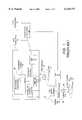
- FIG. 1shows how a CLEC central office 10 can be provided unbundled access to the subscriber lines, ie. the copper pair of wires 22, 32 leading from the ILEC Central Office (CO) 15 to the customer site.
- ILEC Central OfficeCO
- FIG. 1Two configurations of ILEC equipment for servicing customer equipment are shown in FIG. 1, direct copper-wire pair, and remote terminal (e.g. subscriber loop carrier).
- a plurality of copper pairs 22are shown being terminated at a Main Distribution Frame (MDF) 26 located at the ILEC central office 15.
- MDFMain Distribution Frame
- local accessis provided generally by a pair of twisted copper wires, many other local access facilities are available for different bandwidths, such as wireless, fibre optics, coax cable, etc.
- PSTNPublic Subscriber Telephone Network
- Each of these copper pairs 22connects a different Customer Premises Equipment (CPE) connector 20 to the ILEC central office 15, for eventual connection to the Public Subscriber Telephone Network (PSTN).
- CPE devices 21can be POTS, data terminal, fax, ISDN terminal, etc. Though only one CPE connector 20 is shown, there are CPE connectors terminating on each copper pair 22. A plurality of CPE devices 21 can be connected to the CPE connector in the subscriber's premises, all sharing a common copper pair.
- the MDF 26is connected to a line interface module 28 located within the ILEC voice switch 29.
- a CLEC that wishes to have unbundled access to the subscriber line 22must physically connect that subscriber line 22 to its own access device (in this case a line interface module 33), typically located within the physical limits of the ILEC central office 15.
- This access deviceis connected to the CLEC service node (for example, a voice switch) 48.
- the ILEC central office 15has a limited amount of space to accommodate CLEC access devices. As the number of CLECs (each of whom will be deploying their own access devices) increases, the ILEC would suffer physical congestion at its CO 15, the MDF 26 would have to be expanded significantly, both of which could also give rise to administrative difficulties and costs.
- a plurality of copper pairs 32are shown being terminated at a remote Distribution Frame (DF) 36 located at the remote site 16.
- DFremote Distribution Frame
- Each of these copper pairs 32connects a different CPE connectors 30 and CPE devices 31 to the remote site 16, for eventual connection to the ILEC central office 15, and to the Public Subscriber Telephone Network (PSTN).
- PSTNPublic Subscriber Telephone Network
- the remote DF 36is connected to a line interface module 38 which connects to the ILEC service node (voice switch) 29 via a remote line interface termination module 19.
- a CLEC who wishes to have unbundled access to the CPE connector 30must physically connect the copper pair 32 to its own access device (in this case a line interface module 33), typically co-located with the remote line interface termination module 19. This access device is connected to the CLEC service node (voice switch) 48.
- the remote line interface termination module 19is often located on the curb side and co-location can be extremely difficult to implement.
- a second method of providing unbundled access to network servicesis disclosed in U.S. Pat. No. 5,610,910, issued Mar. 11, 1997 (Focsaneanu) (hereinafter referred to as the '910 Patent).
- the '910 Patentdiscloses a method of interfacing Customer Premises Equipment (CPE) connectors and communications networks (such as PSTN, data networks, wireless networks, satellite networks, CATV, ATM networks) through local access.
- CPECustomer Premises Equipment
- communications networkssuch as PSTN, data networks, wireless networks, satellite networks, CATV, ATM networks
- Unbundled access to network servicesis provided without the need for physical unbundling of copper wire pairs.
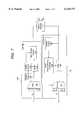
- FIG. 2shows the configuration of equipment that makes up the system disclosed in the '910 patent in which a plurality of CPEs can access a plurality of different service providers offering different services, e.g. PSTN 212, 216 and data switched network 214.
- PSTN 212may be the transport network of one service provider
- data network 214 and PSTN 216may constitute the transport network of one or more different service providers.
- service provider 200there is shown one service provider 200, there are in reality many service providers including PSTN providers, data switched network providers, data network access service providers, etc.
- CPEsare able to seamlessly access various services provided by the service provider 200 through subscriber lines 210, CPE connectors 202, 204, 206 and an access module 208.
- three groups of different CPESe.g. a POTS, data terminal, fax, ISDN terminal etc. are connected to three different CPE connectors 202, 204, 206 with differing capabilities.
- Each CPE connectoroperates with the access module 208 through its local access.
- the access module 208contains a plurality of line interfaces, each interface looking after each local access.
- the access module 208connects service providers who may have their own networks or may utilize any of a plurality of transport networks 212, 214 and 216 for services requested by CPEs.
- three transport networks 212, 214, 216are shown for illustration only.
- the access moduleis capable of routing messages from CPEs to a greater number of transport networks (ILECs, CLECS, or any combination thereof) than the number shown in FIG. 2.
- transport networks(ILECs, CLECS, or any combination thereof)
- ILECstransport networks
- CLECStransport networks
- the access module 208Apart from the hardware present in the access module 208, there is no specialized equipment that needs to be present in the ILEC central office to provide various service providers unbundled access to the CPEs.
- the '910 Patentalso discloses a method for interfacing the CPEs to the multiple service providers offering multiple services.
- the methodincludes a step of the access module 208 extracting information content from traffic to determine requested services of said traffic.
- the methodfurther includes steps of determining appropriate routing for the traffic to/from a plurality of service providers.
- inventive features of the '910 Patentconstitute a real advantage over the implementation of unbundled access described in connection with FIG. 1, in that not only may users have direct access to multiple CLECs, but they may choose different CLECs to carry different kinds of traffic at the same time (ie. POTS, fax, modem, etc.).
- CLECscompeting local exchange carriers
- the use of the generic connectivity network to perform routing between the customer premises equipment and the competing local exchange carrier switchimproves the potential for scaleability, is cost effective, and is easy to administer.
- the present inventionprovides a system for providing competing local exchange carriers access to subscriber access lines and customer premises equipment, the system comprising: a plurality of subscriber lines connecting said customer premises equipment to a line interface module, the line interface module having a first output connected to a service node of an incumbent local exchange carrier and a second output connected to a network interface module, the line interface module being adapted to switch traffic received on a subscriber line selectively to the first output or the second output in accordance with at least one of characteristics of the traffic and parameters associated with the subscriber line; said network interface module being connected to a generic connectivity network, said generic connectivity network having a plurality of interconnected switches and transmission equipment for connecting traffic appearing at the second output of the line interface module to a service node operated by said competing local exchange carrier.
- the customer premises equipmentis comprised of user terminals and a customer premises equipment connector that can transmit and receive any combination of telephone, fax, modem, video, and data signals.
- a line interface moduleis connected to the customer premises equipment by means of subscriber lines for routing the signals originating with the customer premises equipment ("local access signals") to the competing local access switch, instead of the switch operated by the incumbent local exchange carrier.
- a network interface moduleis provided to set up a call path through the generic connectivity network.
- the generic connectivity networkwhich is comprised of a number of interconnected data switches, transmits the local access signals to and from the switch operated by the competing local exchange carrier.
- a network interface modulefor switching cells between a line interface module and a generic connectivity network, said cells consisting of data and a cell header, said network interface module comprising a cell multiplexer portion for multiplexing cells received from said line interface module to form a cell stream; a network interface portion connected to said cell multiplex portion for transmitting and receiving said cell stream to and from said generic connectivity network; and a cell demultiplexer portion for demultiplexing said cell stream to form cells destined for transmission to said line interface module, said cell demultiplexer portion including a traffic shaping/pacing controller for regulating the data rate of said cells.
- a method for establishing a connection between customer premises equipment and a competing local exchange carrierwherein there is a system comprising a plurality of subscriber lines connecting said customer premises equipment to a line interface module controlled by an incumbent local exchange carrier, the line interface module having a first output connected to a service node of the incumbent local exchange carrier and a second output connected to a network interface module, said network interface module being connected to a generic connectivity network, said generic connectivity network having a plurality of interconnected switches and transmission equipment for connecting traffic appearing at the second output of the line interface module to a service node operated by said competing local exchange carrier, said method comprising the steps of: receiving traffic from said subscriber line at said line interface module initiated at said customer premises equipment; said line interface module switching said traffic selectively to the first output or the second output in accordance with at least one of characteristics of the traffic and parameters associated with the subscriber line, if said traffic is switched to said second output, said network interface module receiving said traffic and setting up a traffic path through said generic connectivity network
- FIG. 1is a block diagram showing unbundled access by a Competing Local Exchange Carrier (CLEC) 10 to Customer Premises Equipment (CPE) in accordance with the prior art;
- CLECCompeting Local Exchange Carrier
- CPECustomer Premises Equipment
- FIG. 2is a block diagram showing access to various service providers in accordance with the prior art
- FIG. 3is a block diagram of the major components of the present invention.
- FIG. 4is a block diagram showing the end-to-end connectivity between the end user systems and a plurality of Service Nodes in accordance with the present invention
- FIG. 5is a block diagram of the Customer Premises Equipment (CPE) connector
- FIG. 6is a block diagram of a typical implementation of the line interface module of the present invention.
- FIG. 7is a block diagram of the network interface module of the present invention.
- FIG. 8is a block diagram of the service node interface of the present invention.
- FIG. 9is a block diagram showing the end user systems being connected to a plurality of service providers by means of a generic connectivity network in accordance with the present invention.
- FIG. 3illustrates the major components of the present invention in block diagram form.
- the CPE connector 20 and the attached CPE devices 21are connected to the Main Distribution Frame (MDF) 26 by means of the subscriber access lines 22 which may comprise a twisted pair of copper wires (though the present invention may be used in association with any other local access facility such as wireless, fibre optics, coax cable, etc.).
- a line interface module 39terminates the subscriber access lines 22 and is similar to the line interface module 28 shown in FIG. 1, but contains additional hardware to allow for unbundling and routing to the CLEC service node 48. For traffic that is not to be re-routed to the CLEC central office 10, there is provided a connection 9 within the service node (voice switch) 29 in the ILEC central office 15.
- the service nodeis typically connected to a larger network (not shown), such as the PSTN, to provide the desired services.
- the service nodeis a telephony voice switch but can also be a variety of different service nodes, depending on services subscribed to by a customer.
- NIMNetwork Interface Module
- the switching feature to the NIMis accomplished by provisioning the subscriber line which terminates at the line interface module.
- the provisioning database maintained by the ILECwill determine whether a specific traffic type (voice call, data, video, etc.) received on a subscriber line will be passed through to service node 29, or be switched to the network interface module 45.
- the NIM 45is typically co-located with the line interface module 9 at the ILEC central office 29.
- the NIM 45is typically owned by, and controlled by the ILEC 15.
- trafficcan be routed to any one of the service nodes of the alternate CLEC central offices 66.
- Service nodes operated by CLECscan be voice switches, Internet Service Provider (ISP) gateway, corporate network gateway, video gateway, etc.
- ISPInternet Service Provider
- RLITRemote Line Interface Termination
- NIMnetwork interface module
- the NIM 45is responsible for providing the interface between a plurality of line interface modules 19, 39 to a generic connectivity network 46.
- the line interface modules 19, 39 and the NIM 45allow for a CLEC central office 10 to have unbundled access to the subscriber lines 22, 32 without the need for physical unbundling of twisted copper pairs.
- the present inventiononly requires the provision of one multiplexed connection 49 between the NIM 45 and the generic connectivity network 46.
- the use of the generic connectivity network 46 to perform routing between the CPEs and the service node 48 of the CLEC central office 10improves the potential for scaleability, is cost effective, and is easy to administer. Further details concerning the configuration of the generic connectivity network 46 are provided below.
- the CLEC central office 10 equipmentwhich comprises the service node 48.
- Alternate CLEC central offices 66are also connected to the generic connectivity network, each with their own service node.
- CLEC service nodesmay accommodate any of voice, fax, modem, video, data, etc. traffic.
- the use of a generic connectivity network 46 interspaced between the ILEC 15 and the CLEC central office 10 and line interface modules 19, 39 that can flexibly route connectionsmeans that the CLEC does not have to invest in any equipment that needs to be co-located with ILEC equipment.
- the addition of new CLECsis accomplished by setting up the proper routing information in the NIM 45 and the generic connectivity network 46, and adding a network connection from the generic connectivity network to the new CLEC.
- FIG. 4shows the end-to-end connectivity between the CPE devices 31 and a plurality of CLEC service nodes 48.
- the CPE devices 31could be any of telephone, data terminal, television, fax, ISDN terminal, etc. which are connected to a CPE connector 30.
- the CPE connector 30, which is co-located with the CPE devices 31provides an interface between the CPE devices 31 and the line interface module 39.
- the CPE connector 30also provides the multiplexing function when multiple CPE devices 31 are used at the customer premises. In its simplest form, the CPE connector 30 performs no more than an electrical wired "OR" function.
- the line interface module 39terminates multiple long range interfaces and provides a first stage of multiplexing and concentration.
- the line interface module 39can be based on existing line modules used today to provide mostly voice services.
- Connection 9is provided to existing service nodes (voice switches) operated by the ILEC (such as DMS-100TM, 5ESSTM, etc.), and is used for existing lines and end users who do not require the new functionality disclosed by the present invention.
- the line interface module 39interfaces to another functional unit, the NIM 45, which provides the connectivity to the generic connectivity network 46.
- the NIM 45interfaces with a plurality of line interface modules 39 and provides a second stage of multiplexing and concentration.
- the line interface modules 39 and the NIM 45could be integrated into a single entity, such as the access module 208 illustrated in FIG. 2, with the difference that the access module now uses the generic connectivity network to establish connections to the service nodes.
- the NIM 45provides the necessary interfaces, protocols, etc. required to communicate with the generic connectivity network 46.
- the generic connectivity network 46provides a generic connectivity service to the devices which connect to it. Such a network could be based on any one of, or combination of Asynchronous Transfer Modes (ATM), Internet Protocols (IP), Frame Relay, X.25, Switched Multimegabit Data System (SMDS) networks or any other type of network or combination of networks that allows two end points to communicate with each other.
- the generic connectivity network 46performs the transportation and routing functions necessary to the implementation of the present invention.
- the use of a generic connectivity networkmeans that there is no need for direct connections from the ILEC central office to the CLEC service nodes. Instead, only one network connection 100 per CLEC is needed. This single connection 100 is preferably high-speed and multiplexed, designed to address a very wide geographic area. The bandwidth allocated to this single connection 100 can be easily modified to address changing traffic patterns.
- Connections through the generic connectivity network 46can be established by various methods.
- the generic connectivity network 46is an ATM network
- the NIM 45can request a connection using standard ATM signalling messages (like ATM Forum UNI specification).
- the requestwill state the ATM address of the node to be reached, in this case a service node interface module 47, the required bandwidth and other connection characteristics.
- the ATM switches part of the generic connectivity network 46will take this request and negotiate between them the best way to route the connection (using, for example, ATM Forum PNNI specification).
- the control function of the NIM 45does not have to be physically integrated and could be remoted.
- the information used to set up connectionscomes from ILEC provisioning systems and permanently allocates a given subscriber access line to a given CLEC or service node.
- the subscriber himselfcan request for specific connectivity.
- various signalling methodscan be used, from conventional DTMF to Broadband ISDN (Q2931 standard).
- the signalling informationis sent to a service controller 44 which interprets the signalling information and then proceeds to set up the end to end connection.
- a customercould be accessing different services provided by different CLECs, with all services sharing a common access line 22.
- the service node interface module 47provides an interface between the CLEC service nodes 48 and the generic connectivity network 46. This interface is necessary because the traffic originating with the end users destined to one or more of the service nodes (voice switches) 48 can be of a variety of types (telephony, video, data, etc.).
- the service node interface module 47provides the necessary translations and interworking functions. Of course, service node interface module 47 could be integrated with service nodes (voice switches) 48.
- FIG. 5is a block diagram of an instance of CPE connector 20, which is designed to deal with several types of interfaces 51, 61 connecting to different kinds of CPE devices 31 (such as voice, fax, modem, ISDN, etc.).
- the CPE connector 20just provides an electrical connection between a telephone 31 (which in this example is the CPE device) and the subscriber access line 64.
- the CPE connector 20is shown to have a high-speed interface to the line interface module, allowing multiple user side interfaces 51, 61 to be multiplexed over the same channel 64.
- FIG. 5shows a combination of both of these methods.
- the existing telephony signalsusing the baseband spectrum of about 4-10 KHz is not interfered with through the phone interface 61, and is multiplexed 55 with time multiplexed signals, modulated at higher frequencies by modulator 54.
- the other interfaces 51convert the incoming signals into the digital domain. If those signals are already in digital format, they are then buffered and rate adapted before multiplexing.
- cell formatters 52that cell format the signals into fixed length data packets, where each cell is preceded with an address header.
- An example of the implementation of cell formattingis ATM.
- Variable length packets and fixed allocation of time slotscould also be used.
- the output from the cell formatters 52are time multiplexed by a multiplexer 53 and forwarded to a frequency modulator 54 which encodes the digital data stream in the analog domain, using one of the generally used modulation techniques (e.g. 64 QAM).
- This signalwould be typically mixed 55 with the baseband voice signal and sent to line drivers/receivers block 56 which provides the correct impedance and signal levels for interfacing the subscriber access line 64 to the line interface module (not shown).
- signals from the subscriber access line 64are processed by line drivers/receivers block 56 which restores the proper levels.
- the baseband signalis split off by a filter 57 and the high-speed data is passed to the demodulator 58 which decodes the analog signals back into digital format.
- the multiplexed signalsmust be demultiplexed. Persons skilled in the art will understand that multiple demultiplexing techniques can be used for this purpose.
- the header from the incoming cellsare examined by a header extract 59 and used to drive a demultiplexer 60.
- the cell formattingis removed in cell stripping blocks 63 and forwarded to the user interfaces 51 and CPE devices 31.
- FIG. 5Although only one instance of a customer premises equipment connector is shown in FIG. 5, persons skilled in the art will appreciate that this device can incorporate functionality to communicate with networks which encompass one or more of PSTN, data networks, wireless networks, satellite networks, CATV, ATM networks.
- FIG. 6is a block diagram of a typical implementation of the line interface module.
- a traditional voiceband codec 82is used here to digitize the voice that was left in the analog domain in the CPE. In scenarios where the voice would be digitized in the CPE, the codec 82 would not be required.
- cell formattingwould be provided by an optional cell formatter 73 in the line interface module.
- Modulator 81, demodulator 72, cell formatter 73, cell multiplexers 77, 98, cell demultiplexers 78, 99, cell stripping block 93, cell formatter 95, and header information block 94comprise the additional hardware that is not present in line interface module 28 of FIG. 1. This additional hardware is used to set up an alternative digital path to/from the network interface module. To provide unbundled access uniquely for POTS service, blocks 73, 98, 99 are not required.
- Provisioning information concerning each subscriber line for POTS serviceis stored in the expanded connection memory 102 which will be used to instruct the TDM timeswitch 92 when to switch the incoming calls between the conventional TDM system 101, and the connection 96 to the NIM.
- a TDM timeswitch used in association with the line interface module 28 of FIG. 1would only be required to accommodate two inputs (TDM Mux 85 and conventional TDM system 101) and two outputs (TDM Demux 86 and conventional TDM system 101)
- the expanded TDM timeswitch 92 of FIG. 6must also accommodate a third input (cell stripping 93), and a third output (cell formatting 95).
- a frequency discrimination function taking place in line receiver 71would identify the characteristics of high-speed data traffic destined for cell multiplexer 98.
- high-speed data traffic having frequencies above 10 KHzwould be transmitted to demodulator 72, whereas baseband frequencies between 0 and 10 KHz would be transmitted to Codec 82.
- the optional cell formatter 73formats the high-speed data traffic into cells for multiplexing by cell multiplexer 98 into a cell stream. Cell formatter 73 is required only if the CPE, in simplified implementations, has not already done cell formatting.
- the output from the different line interfaces 166are sent to a cell multiplexer 98 which provides a first level of statistical multiplexing and traffic concentration.
- the cell multiplexer 98can be constructed in several ways. In the example illustrated in FIG.
- a first multiplexer 103places the different inputs on a common bus.
- the header information from each cellis looked up by a header lookup 74 which informs a buffer controller 75 of the incoming traffic.
- the buffer controllerthen decides how to put the information in a common buffer 76.
- a second stage of cell multiplexing 77may be used in cases where the line interface module handles very large numbers of lines.
- cell multiplexer 77will interleave data traffic received from cell mux 98 with POTS call traffic received from cell formatter 95. Multiplexed data in cell format would be carried on communication lines 96 to the network interface module.
- Telephony informationis shown taking a different path 88 to TDM multiplexers 83 (with a second stage of TDM multiplexing 90, if required) before being fed to a timeswitch 92.
- the timeswitch 92provides the channel mapping and concentration functions and is controlled by a local connection memory 102.
- the TDM information from the timeswitchis passed through a cell formatter 95 which uses the information stored in the header information block 94.
- the resulting cell streamis multiplexed by the cell multiplexer 77 with the other cells.
- the information carried on communication line 97 from the network interface moduleis demultiplexed by a cell demultiplexer 78.
- a second stage of demultiplexingmay also be required by cell demultiplexer 99.
- header informationis examined by header lookup 79 and is used to drive a demultiplexer 80.
- the demultiplexed data streamis then sent to different line interfaces 87.
- the cell formattingis removed by a cell stripping 93 and is sent to the timeswitch 92 which will arrange the information in the correct order to send the information to one or several TDM demultiplexers 84, 86, that will eventually arrive at the codec 82.
- the line interface moduleis already interfacing to classical service nodes (voice switches) such as Nortel DMS-100TM
- the interfaces used previously for carrying the telephony information 101can be used for the lines that do not require any more than classical telephony services.
- FIG. 7is a block diagram of the network interface module of the present invention.
- the network interface moduleis responsible for providing the interface to the generic connectivity network for a plurality of line interface modules.
- the generic connectivity networkis an ATM network
- much of the functionality of the NIM(which the exception of traffic shaping/pacing) can be accomplished by an ATM edge switch.
- the incoming information carried on communication line 96is multiplexed by cell multiplexer 155 which is comprised of multiplexer 122, header lookup 112, buffer control 113, buffer 114, and new header insertion 115.
- the cell header informationis then looked up by header lookup 112 and is sent to buffer control 113 which manages how information is written and read from buffer 114.
- buffer control 113controls the header information modification by new header insertion 115 which may be necessary before the cell stream interfaces the generic connectivity network. Where modification is necessary, a destination path identifier and destination channel identifier is written into the cell header.
- the cell stream with the proper header informationis sent via the network interface 116 to the generic connectivity network over communication line 117.
- Traffic received from the generic connectivity network over communication line 123is received at the network interface 116, and sent to cell demultiplexer 156, which is comprised of buffer 120, header lookup 118, traffic shaping/pacing controller 119, and demultiplexer 121.
- the cell header informationis extracted by header lookup 118 and sent to traffic shaping/pacing controller 119 which manages how the information is written and read from the buffer 120. It manages the cell rate destined to any CPE to ensure that the cell rate does not exceed what the end system can receive.
- the generic connectivity networkis an ATM network
- multiple virtual connectionscan be handled by traffic shaping/pacing controller 119 for the purpose of managing group scheduling for a variety of services, each of which having its own data rate.
- the use of the traffic shaping/pacing controller 119avoids buffering requirements in the downstream equipment, and in this embodiment in the line interface module and the CPE controller, thereby reducing the cost and improving the overall efficiency of the network. From the buffer 120, the cell stream is demultiplexed at demultiplexer 121 before being sent to various line interface modules over communication lines 97.
- the network interface modulemay be constructed with hardware to accommodate either the receive path only, or the transmit path only. This would be used in the context of services such as broadcast video which are typically downstream only.
- network interface modulecould be constructed with hardware elements that would support other forms of data transmission, such as Frame Relay, Internet Protocol, Time Division Multiplexing, and Frequency Domain Multiplexing.
- the present inventionis not only restricted to fixed length cells, but is also designed to cover transmissions that comprise variable length cells, such as in a packet switching environment.
- FIG. 8Shown in FIG. 8 is an example for interfacing a conventional telephony switch 147.
- Cell stream from the generic connectivity network over communication line 117is processed by the network interface block 132.
- the cell header informationis extracted by a header extract block 133 and is used to demultiplex the cells by cell demultiplexer 134.
- the cell streamis demultiplexed into two streams, one for control and signalling information 136, and the other for actual voiceband signals 135.
- a CPU 137decodes the information and by the use of different protocols such as GR-303, will communicate with the conventional service node (voice switch) 147 through a communication interface 139.
- the conventional service node (voice switch)will handle this communication in the same manner as any other communication. It does not handle communications from the network implementation of the present invention in any different manner.
- the voiceband informationpasses through a timeswitch 141 where it is re-arranged to match the ordering negotiated between the local CPU 137 emulating GR-303 and the telephony switch.
- Traffic arriving from the conventional service node (voice switch) 145 received over communication line 146is first received by a service node interface 140 and passed through the timeswitch 141.
- the outputis then cell formatted by a cell formatter 142.
- the local CPU 137can insert messages back into the network with its own cell interface 143.
- the different cell streamsare then multiplexed by multiplexer 144 and sent to the network interface module via the network interface 132 and communication line 123.
- FIG. 9is a block diagram showing the end user systems being connected to a plurality of CLECs by means of a generic connectivity network in accordance with the present invention.
- the benefits of using a generic connectivity network for the purposes of routing and transportation of traffic originating with and destined to the CLECsis apparent by examining FIG. 9.
- CPE devices 31are connected to the line interface module 39 by means of the CPE connector 30.
- a plurality of line interface module 39are connected to the NIM 45.
- FIG. 9Shown in FIG. 9 are connections to a wide variety of service providers, including an ILEC network 150, a plurality of CLEC networks 151, a plurality of Internet Service Providers 152, a plurality of corporate networks 153, as well as a plurality of video providers 154. All of these service providers can be accessed by means of the present invention in a manner that is highly scalable, cost effective to deploy, and easy to administer.
- service providersincluding an ILEC network 150, a plurality of CLEC networks 151, a plurality of Internet Service Providers 152, a plurality of corporate networks 153, as well as a plurality of video providers 154. All of these service providers can be accessed by means of the present invention in a manner that is highly scalable, cost effective to deploy, and easy to administer.
Landscapes
- Engineering & Computer Science (AREA)
- Computer Networks & Wireless Communication (AREA)
- Signal Processing (AREA)
- Data Exchanges In Wide-Area Networks (AREA)
- Telephonic Communication Services (AREA)
Abstract
Description
Claims (16)
Priority Applications (3)
| Application Number | Priority Date | Filing Date | Title |
|---|---|---|---|
| US08/958,396US6118777A (en) | 1997-10-27 | 1997-10-27 | System and method for providing competing local exchange carriers unbundled access to subscriber access lines |
| CA002251411ACA2251411A1 (en) | 1997-10-27 | 1998-10-26 | System and method for providing competing local exchange carriers unbundled access to subscriber access lines |
| EP98308748AEP0912071A3 (en) | 1997-10-27 | 1998-10-27 | System and method for providing unbundled access to subscriber access lines |
Applications Claiming Priority (1)
| Application Number | Priority Date | Filing Date | Title |
|---|---|---|---|
| US08/958,396US6118777A (en) | 1997-10-27 | 1997-10-27 | System and method for providing competing local exchange carriers unbundled access to subscriber access lines |
Publications (1)
| Publication Number | Publication Date |
|---|---|
| US6118777Atrue US6118777A (en) | 2000-09-12 |
Family
ID=25500918
Family Applications (1)
| Application Number | Title | Priority Date | Filing Date |
|---|---|---|---|
| US08/958,396Expired - LifetimeUS6118777A (en) | 1997-10-27 | 1997-10-27 | System and method for providing competing local exchange carriers unbundled access to subscriber access lines |
Country Status (3)
| Country | Link |
|---|---|
| US (1) | US6118777A (en) |
| EP (1) | EP0912071A3 (en) |
| CA (1) | CA2251411A1 (en) |
Cited By (36)
| Publication number | Priority date | Publication date | Assignee | Title |
|---|---|---|---|---|
| US6256308B1 (en)* | 1998-01-20 | 2001-07-03 | Telefonaktiebolaget Lm Ericsson | Multi-service circuit for telecommunications |
| US6314108B1 (en)* | 1998-04-30 | 2001-11-06 | Openwave Systems Inc. | Method and apparatus for providing network access over different wireless networks |
| US6317493B1 (en)* | 1998-08-24 | 2001-11-13 | Bell Atlantic Network Services, Inc. | Automated system and method for subscriber line service control |
| US20020091588A1 (en)* | 2001-01-10 | 2002-07-11 | Metasolv Software, Inc. | System and method for mapping information collected in connection with creation of end-user orders for communications services to the corresponding inter-provider orders |
| WO2002073911A1 (en)* | 2001-03-14 | 2002-09-19 | Westwave Communications, Inc. | Sharing remote terminals |
| US6522647B1 (en)* | 1999-08-18 | 2003-02-18 | Nortel Networks Limited | Enhanced VoDSL service provision |
| US6560225B1 (en)* | 1999-08-18 | 2003-05-06 | Nortel Networks Limited | Enhanced performance VoDSL |
| US6594262B1 (en)* | 1997-11-28 | 2003-07-15 | Electronics And Telecommunications Research Institute | Apparatus and method for protecting ATM header from the burst error |
| US20030190031A1 (en)* | 1998-04-08 | 2003-10-09 | Sbc Technology Resources, Inc. | Device and method for transferring unbundled network elements between local exchange carriers |
| US6657994B1 (en)* | 1999-08-25 | 2003-12-02 | Covad Communications Group, Inc. | Uninterrupted transfer of voice telephony service to derived voice technology |
| US6687374B2 (en)* | 2001-06-12 | 2004-02-03 | At&T Wireless Services, Inc. | Multi-service network interface for FDM communications systems |
| US6744871B2 (en)* | 2000-05-12 | 2004-06-01 | Alcatel | Method for routing service calls in a telecommunication network, as well as a telecommunication network, switching center and program module therefor |
| US6747995B1 (en)* | 1998-09-21 | 2004-06-08 | Lucent Technologies Inc. | System for multiple voice lines with data over a single subscriber loop |
| US20040131172A1 (en)* | 2002-09-10 | 2004-07-08 | Keith Gill | Multiline dialing apparatus with interchangeable subscriber service capability |
| US6845248B1 (en)* | 2002-07-09 | 2005-01-18 | Sprint Communications Company L.P. | Broadband wireless shared resource network architecture |
| US20050060169A1 (en)* | 2003-09-15 | 2005-03-17 | Sun Microsystems, Inc. | Frameworks for integrating information systems |
| US20070133772A1 (en)* | 2005-12-14 | 2007-06-14 | Kucera Robert J | Telephone line switching device |
| US20080104452A1 (en)* | 2006-10-26 | 2008-05-01 | Archer Charles J | Providing Policy-Based Application Services to an Application Running on a Computing System |
| US20080148355A1 (en)* | 2006-10-26 | 2008-06-19 | Archer Charles J | Providing Policy-Based Operating System Services in an Operating System on a Computing System |
| US20080313661A1 (en)* | 2007-06-18 | 2008-12-18 | Blocksome Michael A | Administering an Epoch Initiated for Remote Memory Access |
| US20090037707A1 (en)* | 2007-08-01 | 2009-02-05 | Blocksome Michael A | Determining When a Set of Compute Nodes Participating in a Barrier Operation on a Parallel Computer are Ready to Exit the Barrier Operation |
| US20090138892A1 (en)* | 2007-11-28 | 2009-05-28 | Gheorghe Almasi | Dispatching Packets on a Global Combining Network of a Parallel Computer |
| US20090232147A1 (en)* | 2005-10-21 | 2009-09-17 | Siemens Aktiengesellschaft | Method for Forwarding Signalling Data in an Interworking Unit and in a Control Unit and Coprresponding Devices |
| US20090307708A1 (en)* | 2008-06-09 | 2009-12-10 | International Business Machines Corporation | Thread Selection During Context Switching On A Plurality Of Compute Nodes |
| US20100005189A1 (en)* | 2008-07-02 | 2010-01-07 | International Business Machines Corporation | Pacing Network Traffic Among A Plurality Of Compute Nodes Connected Using A Data Communications Network |
| US20100037035A1 (en)* | 2008-08-11 | 2010-02-11 | International Business Machines Corporation | Generating An Executable Version Of An Application Using A Distributed Compiler Operating On A Plurality Of Compute Nodes |
| US7958274B2 (en) | 2007-06-18 | 2011-06-07 | International Business Machines Corporation | Heuristic status polling |
| US20110238949A1 (en)* | 2010-03-29 | 2011-09-29 | International Business Machines Corporation | Distributed Administration Of A Lock For An Operational Group Of Compute Nodes In A Hierarchical Tree Structured Network |
| US8032899B2 (en) | 2006-10-26 | 2011-10-04 | International Business Machines Corporation | Providing policy-based operating system services in a hypervisor on a computing system |
| US8365186B2 (en) | 2010-04-14 | 2013-01-29 | International Business Machines Corporation | Runtime optimization of an application executing on a parallel computer |
| US20130179620A1 (en)* | 2010-07-30 | 2013-07-11 | International Business Machines Corporation | Administering Connection Identifiers For Collective Operations In A Parallel Computer |
| US8565120B2 (en) | 2011-01-05 | 2013-10-22 | International Business Machines Corporation | Locality mapping in a distributed processing system |
| US8689228B2 (en) | 2011-07-19 | 2014-04-01 | International Business Machines Corporation | Identifying data communications algorithms of all other tasks in a single collective operation in a distributed processing system |
| US9065839B2 (en) | 2007-10-02 | 2015-06-23 | International Business Machines Corporation | Minimally buffered data transfers between nodes in a data communications network |
| US9250949B2 (en) | 2011-09-13 | 2016-02-02 | International Business Machines Corporation | Establishing a group of endpoints to support collective operations without specifying unique identifiers for any endpoints |
| US9317637B2 (en) | 2011-01-14 | 2016-04-19 | International Business Machines Corporation | Distributed hardware device simulation |
Families Citing this family (5)
| Publication number | Priority date | Publication date | Assignee | Title |
|---|---|---|---|---|
| SE9902245L (en)* | 1999-06-23 | 2000-10-23 | Ericsson Telefon Ab L M | Device and method of a switched telecommunication system |
| US8285292B1 (en)* | 2000-02-11 | 2012-10-09 | At&T Mobility Ii Llc | Detection of cross-connection between a wireless loop network and another loop network at a subscriber's premises |
| FI114265B (en)* | 2001-03-26 | 2004-09-15 | First Hop Oy | Methods and arrangements for realizing effective data transmission over a speed-limited communication link |
| DE102004043214A1 (en)* | 2004-09-03 | 2006-03-23 | Teles Ag Informationstechnologien | Method for establishing a network-specific telecommunications connection at a called subscriber line of a telecommunications network (reverse preselection, RevPS) |
| DE102007011683B4 (en)* | 2007-03-09 | 2009-06-10 | Adc Gmbh | Termination point line in the subscriber area of a telecommunication and / or data connection and method for provider change |
Citations (14)
| Publication number | Priority date | Publication date | Assignee | Title |
|---|---|---|---|---|
| US5475749A (en)* | 1994-02-28 | 1995-12-12 | At&T Corp. | Connections between a toll network and multiple local networks |
| US5541917A (en)* | 1994-09-12 | 1996-07-30 | Bell Atlantic | Video and TELCO network control functionality |
| US5550912A (en)* | 1994-02-28 | 1996-08-27 | At&T Corp. | Connections between a toll network and multiple local networks |
| US5574783A (en)* | 1995-11-22 | 1996-11-12 | Lucent Technologies Inc. | System and method for providing competitive access telephone service for telephones connected to a remote terminal of the monopoly service provider |
| US5606595A (en)* | 1994-08-19 | 1997-02-25 | Lucent Technologies Inc. | Equal access to inter-exchange carriers in a mobile wireless packet data communication system |
| US5610910A (en)* | 1995-08-17 | 1997-03-11 | Northern Telecom Limited | Access to telecommunications networks in multi-service environment |
| US5673255A (en)* | 1995-12-28 | 1997-09-30 | Lucent Technologies Inc. | Apparatus for providing service to telephone subscribers connected to a remote terminal from multiple telephone service providers |
| US5751951A (en)* | 1995-10-30 | 1998-05-12 | Mitsubishi Electric Information Technology Center America, Inc. | Network interface |
| US5809120A (en)* | 1996-02-09 | 1998-09-15 | Bell Atlantic Network Services, Inc. | Telecommunications network circuit usage measurement |
| US5850444A (en)* | 1996-09-09 | 1998-12-15 | Telefonaktienbolaget L/M Ericsson (Publ) | Method and apparatus for encrypting radio traffic in a telecommunications network |
| US5862203A (en)* | 1995-07-21 | 1999-01-19 | Call Manage | Telecommunications call management system |
| US5862136A (en)* | 1995-07-07 | 1999-01-19 | Northern Telecom Limited | Telecommunications apparatus and method |
| US5903639A (en)* | 1996-11-21 | 1999-05-11 | Bellatlantic Services, Inc. | Custom routing for multiple carrier interconnection |
| US5905781A (en)* | 1996-03-29 | 1999-05-18 | Cisco Technology, Inc. | Communication server apparatus and method |
- 1997
- 1997-10-27USUS08/958,396patent/US6118777A/ennot_activeExpired - Lifetime
- 1998
- 1998-10-26CACA002251411Apatent/CA2251411A1/ennot_activeAbandoned
- 1998-10-27EPEP98308748Apatent/EP0912071A3/ennot_activeWithdrawn
Patent Citations (14)
| Publication number | Priority date | Publication date | Assignee | Title |
|---|---|---|---|---|
| US5550912A (en)* | 1994-02-28 | 1996-08-27 | At&T Corp. | Connections between a toll network and multiple local networks |
| US5475749A (en)* | 1994-02-28 | 1995-12-12 | At&T Corp. | Connections between a toll network and multiple local networks |
| US5606595A (en)* | 1994-08-19 | 1997-02-25 | Lucent Technologies Inc. | Equal access to inter-exchange carriers in a mobile wireless packet data communication system |
| US5541917A (en)* | 1994-09-12 | 1996-07-30 | Bell Atlantic | Video and TELCO network control functionality |
| US5862136A (en)* | 1995-07-07 | 1999-01-19 | Northern Telecom Limited | Telecommunications apparatus and method |
| US5862203A (en)* | 1995-07-21 | 1999-01-19 | Call Manage | Telecommunications call management system |
| US5610910A (en)* | 1995-08-17 | 1997-03-11 | Northern Telecom Limited | Access to telecommunications networks in multi-service environment |
| US5751951A (en)* | 1995-10-30 | 1998-05-12 | Mitsubishi Electric Information Technology Center America, Inc. | Network interface |
| US5574783A (en)* | 1995-11-22 | 1996-11-12 | Lucent Technologies Inc. | System and method for providing competitive access telephone service for telephones connected to a remote terminal of the monopoly service provider |
| US5673255A (en)* | 1995-12-28 | 1997-09-30 | Lucent Technologies Inc. | Apparatus for providing service to telephone subscribers connected to a remote terminal from multiple telephone service providers |
| US5809120A (en)* | 1996-02-09 | 1998-09-15 | Bell Atlantic Network Services, Inc. | Telecommunications network circuit usage measurement |
| US5905781A (en)* | 1996-03-29 | 1999-05-18 | Cisco Technology, Inc. | Communication server apparatus and method |
| US5850444A (en)* | 1996-09-09 | 1998-12-15 | Telefonaktienbolaget L/M Ericsson (Publ) | Method and apparatus for encrypting radio traffic in a telecommunications network |
| US5903639A (en)* | 1996-11-21 | 1999-05-11 | Bellatlantic Services, Inc. | Custom routing for multiple carrier interconnection |
Non-Patent Citations (2)
| Title |
|---|
| Nortel, "Telesis", Issue No. 102, Dec., 1996, pp. 8-11, pp. 14-15. |
| Nortel, Telesis , Issue No. 102, Dec., 1996, pp. 8 11, pp. 14 15.* |
Cited By (68)
| Publication number | Priority date | Publication date | Assignee | Title |
|---|---|---|---|---|
| US6594262B1 (en)* | 1997-11-28 | 2003-07-15 | Electronics And Telecommunications Research Institute | Apparatus and method for protecting ATM header from the burst error |
| US20010036188A1 (en)* | 1998-01-20 | 2001-11-01 | Telefonaktiebolaget L M Ericsson | Multi-service circuit for telecommuncations |
| US6256308B1 (en)* | 1998-01-20 | 2001-07-03 | Telefonaktiebolaget Lm Ericsson | Multi-service circuit for telecommunications |
| US7046787B2 (en)* | 1998-04-08 | 2006-05-16 | Sbc Technologies Resources, Inc. | Device and method for transferring unbundled network elements between local exchange carriers |
| US20050008138A1 (en)* | 1998-04-08 | 2005-01-13 | Sbc Technologies Resources, Inc. | Device and method for transferring unbundled network elements between local exchange carriers |
| US6788776B2 (en)* | 1998-04-08 | 2004-09-07 | Sbc Technology Resources, Inc. | Device and method for transferring unbundled network elements between local exchange carriers |
| US20030190031A1 (en)* | 1998-04-08 | 2003-10-09 | Sbc Technology Resources, Inc. | Device and method for transferring unbundled network elements between local exchange carriers |
| US6314108B1 (en)* | 1998-04-30 | 2001-11-06 | Openwave Systems Inc. | Method and apparatus for providing network access over different wireless networks |
| US6317493B1 (en)* | 1998-08-24 | 2001-11-13 | Bell Atlantic Network Services, Inc. | Automated system and method for subscriber line service control |
| US6453033B1 (en) | 1998-08-24 | 2002-09-17 | Verizon Services Corp. | Automated system and method for subscriber line service control |
| US6747995B1 (en)* | 1998-09-21 | 2004-06-08 | Lucent Technologies Inc. | System for multiple voice lines with data over a single subscriber loop |
| US6560225B1 (en)* | 1999-08-18 | 2003-05-06 | Nortel Networks Limited | Enhanced performance VoDSL |
| US6522647B1 (en)* | 1999-08-18 | 2003-02-18 | Nortel Networks Limited | Enhanced VoDSL service provision |
| US6657994B1 (en)* | 1999-08-25 | 2003-12-02 | Covad Communications Group, Inc. | Uninterrupted transfer of voice telephony service to derived voice technology |
| US6744871B2 (en)* | 2000-05-12 | 2004-06-01 | Alcatel | Method for routing service calls in a telecommunication network, as well as a telecommunication network, switching center and program module therefor |
| US7567923B2 (en)* | 2001-01-10 | 2009-07-28 | Metasolv Software, Inc. | System and method for mapping information collected in connection with creation of end-user orders for communications services to the corresponding inter-provider orders |
| US20020091588A1 (en)* | 2001-01-10 | 2002-07-11 | Metasolv Software, Inc. | System and method for mapping information collected in connection with creation of end-user orders for communications services to the corresponding inter-provider orders |
| WO2002073911A1 (en)* | 2001-03-14 | 2002-09-19 | Westwave Communications, Inc. | Sharing remote terminals |
| US6687374B2 (en)* | 2001-06-12 | 2004-02-03 | At&T Wireless Services, Inc. | Multi-service network interface for FDM communications systems |
| US6845248B1 (en)* | 2002-07-09 | 2005-01-18 | Sprint Communications Company L.P. | Broadband wireless shared resource network architecture |
| US20040131172A1 (en)* | 2002-09-10 | 2004-07-08 | Keith Gill | Multiline dialing apparatus with interchangeable subscriber service capability |
| US20050060169A1 (en)* | 2003-09-15 | 2005-03-17 | Sun Microsystems, Inc. | Frameworks for integrating information systems |
| US8266326B2 (en)* | 2003-09-15 | 2012-09-11 | Oracle America, Inc. | Frameworks for integrating information systems |
| US9356973B2 (en) | 2005-10-21 | 2016-05-31 | Siemens Aktiengesellschaft | Method for the transmission of signalling data in a network interface unit and in a control unit and corresponding devices |
| US20110181682A1 (en)* | 2005-10-21 | 2011-07-28 | Siemens Aktiengesellschaft | Method for the transmission of signalling data in a network interface unit and in a control unit and corrsponding devices |
| US20090232147A1 (en)* | 2005-10-21 | 2009-09-17 | Siemens Aktiengesellschaft | Method for Forwarding Signalling Data in an Interworking Unit and in a Control Unit and Coprresponding Devices |
| US8036234B2 (en)* | 2005-10-21 | 2011-10-11 | Siemens Aktiengesellschaft | Method for forwarding signalling data in an interworking unit and in a control unit and corresponding devices |
| US7616759B2 (en)* | 2005-12-14 | 2009-11-10 | Kucera Robert J | Telephone line switching device |
| US20070133772A1 (en)* | 2005-12-14 | 2007-06-14 | Kucera Robert J | Telephone line switching device |
| US8713582B2 (en) | 2006-10-26 | 2014-04-29 | International Business Machines Corporation | Providing policy-based operating system services in an operating system on a computing system |
| US8656448B2 (en) | 2006-10-26 | 2014-02-18 | International Business Machines Corporation | Providing policy-based application services to an application running on a computing system |
| US20080148355A1 (en)* | 2006-10-26 | 2008-06-19 | Archer Charles J | Providing Policy-Based Operating System Services in an Operating System on a Computing System |
| US20080104452A1 (en)* | 2006-10-26 | 2008-05-01 | Archer Charles J | Providing Policy-Based Application Services to an Application Running on a Computing System |
| US8032899B2 (en) | 2006-10-26 | 2011-10-04 | International Business Machines Corporation | Providing policy-based operating system services in a hypervisor on a computing system |
| US7958274B2 (en) | 2007-06-18 | 2011-06-07 | International Business Machines Corporation | Heuristic status polling |
| US8296430B2 (en) | 2007-06-18 | 2012-10-23 | International Business Machines Corporation | Administering an epoch initiated for remote memory access |
| US20080313661A1 (en)* | 2007-06-18 | 2008-12-18 | Blocksome Michael A | Administering an Epoch Initiated for Remote Memory Access |
| US8676917B2 (en) | 2007-06-18 | 2014-03-18 | International Business Machines Corporation | Administering an epoch initiated for remote memory access |
| US8346928B2 (en) | 2007-06-18 | 2013-01-01 | International Business Machines Corporation | Administering an epoch initiated for remote memory access |
| US20090037707A1 (en)* | 2007-08-01 | 2009-02-05 | Blocksome Michael A | Determining When a Set of Compute Nodes Participating in a Barrier Operation on a Parallel Computer are Ready to Exit the Barrier Operation |
| US8082424B2 (en) | 2007-08-01 | 2011-12-20 | International Business Machines Corporation | Determining when a set of compute nodes participating in a barrier operation on a parallel computer are ready to exit the barrier operation |
| US9065839B2 (en) | 2007-10-02 | 2015-06-23 | International Business Machines Corporation | Minimally buffered data transfers between nodes in a data communications network |
| US20090138892A1 (en)* | 2007-11-28 | 2009-05-28 | Gheorghe Almasi | Dispatching Packets on a Global Combining Network of a Parallel Computer |
| US7984450B2 (en) | 2007-11-28 | 2011-07-19 | International Business Machines Corporation | Dispatching packets on a global combining network of a parallel computer |
| US9459917B2 (en) | 2008-06-09 | 2016-10-04 | International Business Machines Corporation | Thread selection according to power characteristics during context switching on compute nodes |
| US8458722B2 (en) | 2008-06-09 | 2013-06-04 | International Business Machines Corporation | Thread selection according to predefined power characteristics during context switching on compute nodes |
| US20090307708A1 (en)* | 2008-06-09 | 2009-12-10 | International Business Machines Corporation | Thread Selection During Context Switching On A Plurality Of Compute Nodes |
| US8140704B2 (en)* | 2008-07-02 | 2012-03-20 | International Busniess Machines Corporation | Pacing network traffic among a plurality of compute nodes connected using a data communications network |
| US20100005189A1 (en)* | 2008-07-02 | 2010-01-07 | International Business Machines Corporation | Pacing Network Traffic Among A Plurality Of Compute Nodes Connected Using A Data Communications Network |
| US8495603B2 (en) | 2008-08-11 | 2013-07-23 | International Business Machines Corporation | Generating an executable version of an application using a distributed compiler operating on a plurality of compute nodes |
| US20100037035A1 (en)* | 2008-08-11 | 2010-02-11 | International Business Machines Corporation | Generating An Executable Version Of An Application Using A Distributed Compiler Operating On A Plurality Of Compute Nodes |
| US8606979B2 (en) | 2010-03-29 | 2013-12-10 | International Business Machines Corporation | Distributed administration of a lock for an operational group of compute nodes in a hierarchical tree structured network |
| US20110238949A1 (en)* | 2010-03-29 | 2011-09-29 | International Business Machines Corporation | Distributed Administration Of A Lock For An Operational Group Of Compute Nodes In A Hierarchical Tree Structured Network |
| US8893150B2 (en) | 2010-04-14 | 2014-11-18 | International Business Machines Corporation | Runtime optimization of an application executing on a parallel computer |
| US8365186B2 (en) | 2010-04-14 | 2013-01-29 | International Business Machines Corporation | Runtime optimization of an application executing on a parallel computer |
| US8898678B2 (en) | 2010-04-14 | 2014-11-25 | International Business Machines Corporation | Runtime optimization of an application executing on a parallel computer |
| US8504732B2 (en) | 2010-07-30 | 2013-08-06 | International Business Machines Corporation | Administering connection identifiers for collective operations in a parallel computer |
| US9053226B2 (en)* | 2010-07-30 | 2015-06-09 | International Business Machines Corporation | Administering connection identifiers for collective operations in a parallel computer |
| US20130179620A1 (en)* | 2010-07-30 | 2013-07-11 | International Business Machines Corporation | Administering Connection Identifiers For Collective Operations In A Parallel Computer |
| US8504730B2 (en) | 2010-07-30 | 2013-08-06 | International Business Machines Corporation | Administering connection identifiers for collective operations in a parallel computer |
| US9246861B2 (en) | 2011-01-05 | 2016-01-26 | International Business Machines Corporation | Locality mapping in a distributed processing system |
| US8565120B2 (en) | 2011-01-05 | 2013-10-22 | International Business Machines Corporation | Locality mapping in a distributed processing system |
| US9317637B2 (en) | 2011-01-14 | 2016-04-19 | International Business Machines Corporation | Distributed hardware device simulation |
| US9607116B2 (en) | 2011-01-14 | 2017-03-28 | International Business Machines Corporation | Distributed hardware device simulation |
| US8689228B2 (en) | 2011-07-19 | 2014-04-01 | International Business Machines Corporation | Identifying data communications algorithms of all other tasks in a single collective operation in a distributed processing system |
| US9229780B2 (en) | 2011-07-19 | 2016-01-05 | International Business Machines Corporation | Identifying data communications algorithms of all other tasks in a single collective operation in a distributed processing system |
| US9250948B2 (en) | 2011-09-13 | 2016-02-02 | International Business Machines Corporation | Establishing a group of endpoints in a parallel computer |
| US9250949B2 (en) | 2011-09-13 | 2016-02-02 | International Business Machines Corporation | Establishing a group of endpoints to support collective operations without specifying unique identifiers for any endpoints |
Also Published As
| Publication number | Publication date |
|---|---|
| EP0912071A2 (en) | 1999-04-28 |
| CA2251411A1 (en) | 1999-04-27 |
| EP0912071A3 (en) | 2001-08-22 |
Similar Documents
| Publication | Publication Date | Title |
|---|---|---|
| US6118777A (en) | System and method for providing competing local exchange carriers unbundled access to subscriber access lines | |
| EP0968586B1 (en) | Network access in multi-service environment | |
| EP0845186B1 (en) | An improved access to telecommunications networks in multi-service environment | |
| EP0995335B1 (en) | Method and apparatus for providing broadband access conferencing services | |
| US6128293A (en) | Multiservice access management system | |
| US6075784A (en) | System and method for communicating voice and data over a local packet network | |
| US6307836B1 (en) | High-speed transparent access to multiple services | |
| US5959996A (en) | System for interfacing numerous ISDN data connecting to a data network through the telephone network | |
| CN1113514C (en) | Line card with modem interface | |
| EP1865665A2 (en) | Wide area communication networking | |
| JP2002518915A (en) | Switching of system data interface | |
| WO2003061226A1 (en) | Telephone line rollover service for atm/adsl based systems | |
| EP0983693B1 (en) | Control of communication traffic | |
| EP1076473A1 (en) | Method and a network node for selectively transferring data to multiple networks | |
| CN1613235A (en) | Method and system for voice traffic concentration in an ATM/DSL head-end network | |
| US20020057676A1 (en) | Method and system for communicating ISDN over ATM-based next generation access networks using primary rate interface | |
| HU222934B1 (en) | Telecommunication system and method for providing a digital telephone line | |
| US20020009099A1 (en) | Broadband access to multiple dwelling units for voice and data communications | |
| US7436851B1 (en) | Destination call routing apparatus and method | |
| AU721715B2 (en) | Arrangement for interleaving data and signalling information | |
| Schaffer | Switching in the broad-band ISDN | |
| Boulter | The Integrated Services Digital Network | |
| Groom et al. | Emerging High-Bandwidth Networks | |
| Hardy et al. | The beginnings of high-speed packet mode networks | |
| MXPA00012099A (en) | System and method for communicating voice and data over a local packet network |
Legal Events
| Date | Code | Title | Description |
|---|---|---|---|
| AS | Assignment | Owner name:BELL-NORTHERN RESEARCH LTD., CANADA Free format text:ASSIGNMENT OF ASSIGNORS INTEREST;ASSIGNOR:SYLVAIN, DANY;REEL/FRAME:008868/0627 Effective date:19971020 | |
| AS | Assignment | Owner name:NORTHERN TELECOM LIMITED, CANADA Free format text:ASSIGNMENT OF ASSIGNORS INTEREST;ASSIGNOR:BELL-NORTHERN RESEARCH LTD.;REEL/FRAME:009210/0382 Effective date:19980520 | |
| AS | Assignment | Owner name:NORTEL NETWORKS CORPORATION, CANADA Free format text:CHANGE OF NAME;ASSIGNOR:NORTHERN TELECOM LIMITED;REEL/FRAME:010567/0001 Effective date:19990429 | |
| STCF | Information on status: patent grant | Free format text:PATENTED CASE | |
| AS | Assignment | Owner name:NORTEL NETWORKS LIMITED, CANADA Free format text:CHANGE OF NAME;ASSIGNOR:NORTEL NETWORKS CORPORATION;REEL/FRAME:011195/0706 Effective date:20000830 Owner name:NORTEL NETWORKS LIMITED,CANADA Free format text:CHANGE OF NAME;ASSIGNOR:NORTEL NETWORKS CORPORATION;REEL/FRAME:011195/0706 Effective date:20000830 | |
| FPAY | Fee payment | Year of fee payment:4 | |
| FPAY | Fee payment | Year of fee payment:8 | |
| AS | Assignment | Owner name:ROCKSTAR BIDCO, LP, NEW YORK Free format text:ASSIGNMENT OF ASSIGNORS INTEREST;ASSIGNOR:NORTEL NETWORKS LIMITED;REEL/FRAME:027164/0356 Effective date:20110729 | |
| FPAY | Fee payment | Year of fee payment:12 | |
| AS | Assignment | Owner name:ROCKSTAR CONSORTIUM US LP, TEXAS Free format text:ASSIGNMENT OF ASSIGNORS INTEREST;ASSIGNOR:ROCKSTAR BIDCO, LP;REEL/FRAME:032106/0063 Effective date:20120509 | |
| AS | Assignment | Owner name:CONSTELLATION TECHNOLOGIES LLC, TEXAS Free format text:ASSIGNMENT OF ASSIGNORS INTEREST;ASSIGNOR:ROCKSTAR CONSORTIUM US LP;REEL/FRAME:032162/0524 Effective date:20131113 | |
| AS | Assignment | Owner name:RPX CLEARINGHOUSE LLC, CALIFORNIA Free format text:ASSIGNMENT OF ASSIGNORS INTEREST;ASSIGNORS:ROCKSTAR CONSORTIUM US LP;ROCKSTAR CONSORTIUM LLC;BOCKSTAR TECHNOLOGIES LLC;AND OTHERS;REEL/FRAME:034924/0779 Effective date:20150128 | |
| AS | Assignment | Owner name:JPMORGAN CHASE BANK, N.A., AS COLLATERAL AGENT, IL Free format text:SECURITY AGREEMENT;ASSIGNORS:RPX CORPORATION;RPX CLEARINGHOUSE LLC;REEL/FRAME:038041/0001 Effective date:20160226 | |
| AS | Assignment | Owner name:RPX CLEARINGHOUSE LLC, CALIFORNIA Free format text:RELEASE (REEL 038041 / FRAME 0001);ASSIGNOR:JPMORGAN CHASE BANK, N.A.;REEL/FRAME:044970/0030 Effective date:20171222 Owner name:RPX CORPORATION, CALIFORNIA Free format text:RELEASE (REEL 038041 / FRAME 0001);ASSIGNOR:JPMORGAN CHASE BANK, N.A.;REEL/FRAME:044970/0030 Effective date:20171222 |