US6118382A - System and method for alerting safety personnel of unsafe air temperature conditions - Google Patents
System and method for alerting safety personnel of unsafe air temperature conditionsDownload PDFInfo
- Publication number
- US6118382A US6118382AUS09/182,823US18282398AUS6118382AUS 6118382 AUS6118382 AUS 6118382AUS 18282398 AUS18282398 AUS 18282398AUS 6118382 AUS6118382 AUS 6118382A
- Authority
- US
- United States
- Prior art keywords
- temperature
- indicator
- signal
- unsafe
- coupled
- Prior art date
- Legal status (The legal status is an assumption and is not a legal conclusion. Google has not performed a legal analysis and makes no representation as to the accuracy of the status listed.)
- Expired - Lifetime
Links
Images


Classifications
- G—PHYSICS
- G08—SIGNALLING
- G08B—SIGNALLING OR CALLING SYSTEMS; ORDER TELEGRAPHS; ALARM SYSTEMS
- G08B21/00—Alarms responsive to a single specified undesired or abnormal condition and not otherwise provided for
- G08B21/02—Alarms for ensuring the safety of persons
- A—HUMAN NECESSITIES
- A62—LIFE-SAVING; FIRE-FIGHTING
- A62B—DEVICES, APPARATUS OR METHODS FOR LIFE-SAVING
- A62B9/00—Component parts for respiratory or breathing apparatus
- G—PHYSICS
- G08—SIGNALLING
- G08B—SIGNALLING OR CALLING SYSTEMS; ORDER TELEGRAPHS; ALARM SYSTEMS
- G08B17/00—Fire alarms; Alarms responsive to explosion
- G08B17/06—Electric actuation of the alarm, e.g. using a thermally-operated switch
- G—PHYSICS
- G08—SIGNALLING
- G08B—SIGNALLING OR CALLING SYSTEMS; ORDER TELEGRAPHS; ALARM SYSTEMS
- G08B19/00—Alarms responsive to two or more different undesired or abnormal conditions, e.g. burglary and fire, abnormal temperature and abnormal rate of flow
- G08B19/02—Alarm responsive to formation or anticipated formation of ice
- G—PHYSICS
- G08—SIGNALLING
- G08B—SIGNALLING OR CALLING SYSTEMS; ORDER TELEGRAPHS; ALARM SYSTEMS
- G08B21/00—Alarms responsive to a single specified undesired or abnormal condition and not otherwise provided for
- G08B21/18—Status alarms
- G08B21/20—Status alarms responsive to moisture
Definitions
- the present inventionrelates in general to the field of equipment for firefighters and other safety personnel, and, more particularly, to a system and method for alerting safety personnel of unsafe air temperature conditions.
- Firefighters and other safety personneluse various types of equipment when fighting a fire.
- This equipmenttypically includes a coat, boots, gloves and other clothing specially created to protect against fire and heat as well as a self contained breathing apparatus to provide oxygen.
- firefighter'sstill face significant dangers including the danger of a flashover.
- the ambient temperature in a firereaches about 600 degrees Fahrenheit, the temperature will quickly rise to over 1100 degrees Fahrenheit. At this point, a flashover can occur in which the air ignites and kills or severely injures firefighters. Thus, it is unsafe to fight fires once the ambient temperature reaches around 600 degrees Fahrenheit.
- U.S. Pat. No. 5,640,148discloses a dual activation alarm system for a personal alert safety system (PASS).
- U.S. Pat. No. 5,635,909discloses a temperature monitoring assembly that is incorporated into a garment such as a coat. This device includes a speaker to provide an audible alarm.
- U.S. Pat. No. 5,541,549discloses a personal alarm safety system that is designed as part of the firefighter's belt.
- U.S. Pat. No. 5,137,378discloses an integrated firefighter safety monitoring and alarm system that provides a number of warnings to a firefighter.
- This systemincludes temperature monitoring and provides an audible alarm.
- the systemalso has a display for providing additional information to the firefighter including a visible warning.
- the systemis contained in a case that can have a belt or mounting clip for attaching to the firefighter's equipment.
- a system and method for alerting safety personnel of unsafe air temperature conditionsare disclosed that provide advantages over previously developed temperature warning equipment.
- the present systemincludes a temperature sensor formed to be exposed to an ambient environment and operable to provide a signal representing a measured ambient temperature.
- the systemalso includes electronics formed to be attached within protection provided by safety equipment. The electronics are coupled to receive the signal from the temperature sensor. The electronics are then operable to process the signal, to detect an unsafe temperature condition and to provide an indicator signal responsive to the unsafe temperature condition.
- the systemfurther includes an indicator coupled to receive the indicator signal from the electronics. The indicator then responds to the indicator signal by providing a visible indication of the unsafe temperature condition.
- the unsafe temperature conditioncan comprise the measured ambient temperature being above a temperature set point or being above a specified temperature for a specified period of time.
- the temperature sensorcan be coupled to the electronics by a through-screw sensor assembly.
- a methodfor alerting safety personnel of unsafe air temperature conditions.
- the methodincludes measuring ambient temperature and detecting an unsafe temperature condition. Then, a visible indication of the unsafe temperature condition is provided within the peripheral vision of safety personnel.
- a technical advantage of the present inventionis the providing of indicators and/or alarms to safety personnel focused upon the personal safety of the firefighter.
- the trigger pointsrather than being focused on equipment safety, focus upon the safety personnel.
- Another technical advantage of the present inventionis the ease of use in that the temperature indicators are positioned within the personnel's peripheral vision near the face mask of a self contained breathing apparatus.
- the present inventioncan help save lives by providing a passively visible warning that the environment is approaching flashover conditions. Further, the present invention may save on taxpayer's funds that would have otherwise been spent on fire suit replacements, compensation packages and downtime costs.
- FIG. 1is a block diagram of one embodiment of a system for alerting safety personnel of unsafe air temperature conditions constructed according to the present invention
- FIG. 2is a flow chart of one embodiment of a method for alerting safety personnel of unsafe air temperature conditions according to the present invention
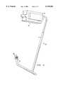
- FIG. 3is a perspective view of one embodiment of a system for alerting safety personnel of unsafe air temperature conditions constructed according to the present invention.
- FIG. 4is a perspective view of one embodiment of the system of FIG. 3 affixed to a self contained breathing apparatus face piece according to the present invention
- FIG. 5is a block diagram of another embodiment of a system for alerting safety personnel of unsafe air temperature conditions.
- FIGS. 6A, 6B, 6C, 6D and 6Eare diagrams of one embodiment of a through-screw sensor assembly for a system for alerting safety personnel of unsafe air temperature conditions constructed according to the present invention.
- FIG. 1is a block diagram of one embodiment of a system, indicated generally at 10, for alerting safety personnel of unsafe air temperature conditions constructed according to the present invention.
- system 10has a microprocessor 12 that receives power from a battery 14.
- Microprocessor 12serves as a control unit for system 10, which control unit, it should be understood, could comprise other types of control devices.
- Battery 14can be replaced by the user and can be conserved by switching system 10 off when not in use.
- System 10also includes a low battery voltage detect circuit 16 and can be turned on and off by an on/off switch 18 and test push-button 18. This switch 18 can be backed up by an automatic switch (not shown) that turns system 10 on when the ambient temperature reaches a certain point, such as is 150 degrees Fahrenheit.
- a temperature sensor 22measures temperature and provides an output to a comparator circuit 24 which has digital potentiometers for adjustable indicator set points.
- Temperature sensor 22can, for example, be a resistive temperature device (RTD), thermocouple, thermistor or infra-red (IR) sensor.
- RTDresistive temperature device
- IRinfra-red
- system 10has dual thresholds, but it should be understood that more thresholds could be implemented if appropriate.
- digital potentiometerscan be set by signals from microprocessor 12.
- comparator circuit 24provides a signal to microprocessor 12 in response to a comparison between the digital potentiometers and the output from temperature sensor 22.
- Microprocessor 12then provides signals to drive two visible indicators 28, as shown.
- These visible indicators 28can, for example, be LED, LCD, heads-up-display, fiber optic or incandescent indicators.
- visible indicators 28are LED's and indicate an ambient temperature of 300 degrees Fahrenheit and 600 degrees Fahrenheit, respectively. However, these settings are variable and could be other values.
- Further microprocessor 12can provide signals to an optional alarm 30.
- the alarmcan, for example, be an audible or vibration alarm.
- the microprocessor control of system 10can provide additional enhancements to temperature monitoring for the safety of safety personnel.
- system 10can utilize time averaged measurements for additional or alternate indicators. Such time averaged measurements identify the fact that the safety personnel has been at a given ambient temperature for a given amount of time. Examples of time averaged measurements include: 160 degrees Fahrenheit for 60 seconds, 180 degrees Fahrenheit for 30 seconds, 212 degrees Fahrenheit for 15 seconds, and 500 degrees Fahrenheit for 60 seconds.
- System 10can react to such events by providing additional visible indicators and alarms.
- Another enhanced featureis an ability to record and provide a temperature history for a post-event analysis. For example, the temperature could be recorded at specified intervals of time while the firefighter or other safety personnel is working to give an idea of the temperature profile within the site. Further, this could be linked with positioning information, such as from GPS equipment, to "map" the temperature gradients within the site. The recording can, for example, be into on-board random access memory.
- system 10One purpose of system 10 is to provide firefighter and other safety personnel with an early warning of excessive temperatures that would eventually lead to a flashover or other danger.
- the temperaturewill start rising, and it takes around 2 minutes, linearly, to reach 600 degrees Fahrenheit. Once the temperature reaches that threshold, the temperature will start rising exponentially to over 1100 degrees Fahrenheit in less than a minute. This fatal phenomenon is termed a flashover. It is appropriate to evacuate buildings or other structures once the temperature reaches around 600 degrees Fahrenheit. Further, other temperature related conditions can be unsafe for firefighters. For example, as mentioned above, remaining in a high ambient temperature for a certain period of time can be dangerous.
- the present inventionprovides a system that generally incorporates a remote temperature sensing device encapsulated with batteries and indicators (e.g., green and red LED's) within an insulated enclosure which is mounted within the peripheral vision of the self-contained breathing apparatus (SCBA) that firefighters wear.
- the green and red LED'swill glow the moment the ambient temperature rises above 300 degrees Fahrenheit or 600 degrees Fahrenheit, respectively. This early signaling will afford firefighters with ample time to react to the situation and make informed decisions as to whether to proceed or revert.
- the present inventionsave many firefighter's lives, but, in turn, will also save on taxpayer's funds that would have otherwise been spent on fire suit replacements, firefighter's compensation packages and downtime costs.
- FIG. 2is a flow chart of one embodiment of a method for alerting safety personnel of unsafe air temperature conditions according to the present invention.
- the start switchis activated. This activation can be manual or automatic as mentioned above.
- the systembegins an internal self test.
- the systemchecks whether the battery is low. If so, in step 43, the system flashes one of the indicators to signal the problem.
- the systemdetermines whether the self-test failed. If so, in step 45, the system flashes the other indicator to signal this failure. If the tests do not fail, in step 46, the system illuminates both indicators for five seconds and beeps the installed speaker (if any).
- step 48the system then allows a user to program the digital potentiometers for the temperature set points. This can be an optional step if the digital potentiometers are already set. Then, in step 50, the system measures the ambient temperature on an ongoing basis using the temperature sensor. In step 52, the system determines it is switched off. If so, then the process stops. Otherwise, the system checks, in step 54, whether the temperature is at the first set point (e.g., 300 degrees Fahrenheit) or greater. If not, then the system returns to measuring the temperature. If the temperature is greater than 300 degrees Fahrenheit, then the system illuminates the first indicator in step 55. Then, in step 56, the system checks whether the temperature is greater than the second set point (e.g, 600 degrees Fahrenheit).
- the first set pointe.g. 300 degrees Fahrenheit
- the systemreturns to measuring the temperature of step 50. If the temperature is greater than 600 degrees Fahrenheit, then the system illuminates the second indicator in step 58 and then returns to measure temperature, as shown. In this manner, the system continually monitors the ambient temperature and provides a visible warning of the ambient temperature is above either of the temperature set points. It should be understood that other implementations would include other steps. For example, an implementation having time averaged measurements would involve steps for averaging temperature over a specified interval of time and alerting a firefighter or other safety personnel when certain conditions have been met.
- FIG. 3is a perspective view of one embodiment of an system, indicated generally at 60, for alerting safety personnel of unsafe air temperature conditions constructed according to the present invention.
- system 60comprises electronics 62 that are contained primarily in a housing 64 with the exception of visible indicators 66 and a sensor 68 which are positioned at the end of an arm 70 extending from housing 64.
- sensor 68 and indicators 66 on arm 70can be exposed to the ambient temperatures, while the remaining portions of system 60 are protected within the firefighters equipment. Further, this allows the sensor 68 and indicators 66 to be easily replaceable with a detachable arm 70.
- Electronics 62can be implemented, for example, according to the block diagram of FIG. 1, above.
- FIG. 4is a perspective view of one embodiment of system 60 of FIG. 3 affixed to a self contained breathing apparatus face piece 72 according to the present invention.
- housing 64 of system 60is attached to face piece 72 which is coupled to a firefighter's helmet.
- a arm 70then extends from housing 64 and positions indicators 66 within the peripheral vision of the firefighter. In this manner, the firefighter can passively see indicators 66 without actively having to look away or otherwise take attention away from firefighting tasks.
- system 60can be a completely self-contained unit attached to the firefighter's self-contained breathing apparatus (SCBA) face piece 72.
- SCBAfirefighter's self-contained breathing apparatus
- System 60operates to alert a firefighter when the ambient temperature has reached an unsafe level, for example, that would lead to a flashover.
- System 60can be mounted in a fashion such that indicators 66 (e.g., LEDs), which turn on at pre-determined temperatures are other defined conditions, lie within the firefighter's peripheral vision.
- a switchcan turn system 60 on and also can serve as a daily test button.
- a successful self-testcan illuminate indicators 66, then turn them off and allow a speaker to beep (if present). If there is a problem with electronics 62, indicators 38 can flash an error sequence when system 60 is switched on. Also, the power switch can be backed up by an automatic switch that turns system 60 on when the ambient temperature reaches a specified point.
- visible indicatorsare placed in the field of view, for example, while a firefighter is fighting a fire.
- a first set pointe.g. 300° F.
- the first indicatorwill be illuminated and will stay on as long as the temperature is at the set point or above.
- the second set pointe.g., 600° F.
- the second indicatorwill illuminate and will stay on as long as the temperature is at that set point or above.
- the second indicatorcan indicate that there is a very short time period before temperatures reach a point at which flashover could occur. At this point, the firefighter (or other personnel) should consider immediately leaving the area to avoid a life threatening situation.
- the first set pointcan be set at the face piece manufacturer's suggested temperature rating for the normal functioning of the face piece to serve as an equipment failure warning.
- the temperature set pointscan be varied by reprogramming of the digital potentiometers to provide alerts as to other unsafe conditions.
- FIG. 5is a block diagram of another embodiment of a system, indicated generally at 80, for alerting safety personnel of unsafe air temperature conditions.
- system 80is similar to system of FIG. 10 of FIG. 1.
- system 80has a microprocessor 82 that receives power from a battery and low voltage detection circuit 84.
- Microprocessor 82serves as a control unit for system 80, which could comprise alternate types of control devices as mentioned above.
- System 80can be turned on and off by an on/off switch 86 which also can operate as a test push-button.
- a temperature sensor 88measures temperature and provides an output to a comparator circuit or A/D converter 90 of microprocessor 82.
- Microprocessor 82then provides signals to visible indicators 92 which have variable set points for indicating ambient temperature levels (e.g., 140° F. and 400° F.).
- comparator circuit or A/D convertor 90provides a signal to microprocessor 82 in response to a measurement by temperature sensor 88.
- Microprocessor 82then provides signals to drive visible indicators 92.
- Further microprocessor 82can provide signals to an optional vibration alarm 94 (e.g., mechanical motor, solenoid) and audible alarm 96.
- microprocessor 82comprises a serial port 98 which can output data to an infrared data port 100 for external interface to system 80. This could be user, for example, to recover a recorded temperature history or other pertinent information.
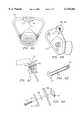
- FIGS. 6A, 6B, 6C, 6D and 6Eare diagrams of one embodiment of a through-screw sensor assembly for a system for alerting safety personnel of unsafe air temperature conditions constructed according to the present invention.
- a face mask 110receives a through-screw sensor assembly, indicated generally at 112.
- Assembly 112includes a pair of visible indicators 114 positioned within the range of vision of personnel wearing face mask 110.
- FIG. 6Bis a side view of face mask 110.
- FIG. 6also indicates an area shown in more detail in FIG. 6C.
- FIG. 6Cprovides a detailed view of assembly 112 affixed to face mask 110.
- assembly 112comprises a hollow Allen head screw 116 which is coupled to fac mask 110.
- Assembly 112further comprises a nut 118 positioned outside a front portion 120 of face mask 110 and a washer 122 position inside front portion 120.
- screw 116, nut 118 and washer 122removably attach to front portion 120.
- FIG. 6Dprovides an explosion view of these same components of assembly 112.
- FIG. 6Eprovides a cross section diagram of screw 116.
- screw 116has a hollow center 126 which can provide a connection to a resistive temperature device (RTD) 128.
- RTDresistive temperature device
- assembly 112provides an advantageous means for mounting a sensor on face mask 110.
- assembly 112is adapted to conventional face masks 110 which include a screw assembly for holding the visor. This screw assembly can easily be replaced by assembly 112 in installing the present invention.
Landscapes
- Business, Economics & Management (AREA)
- Emergency Management (AREA)
- Physics & Mathematics (AREA)
- General Physics & Mathematics (AREA)
- Health & Medical Sciences (AREA)
- Pulmonology (AREA)
- General Health & Medical Sciences (AREA)
- Emergency Alarm Devices (AREA)
Abstract
Description
Claims (21)
Priority Applications (3)
| Application Number | Priority Date | Filing Date | Title |
|---|---|---|---|
| US09/182,823US6118382A (en) | 1997-10-30 | 1998-10-29 | System and method for alerting safety personnel of unsafe air temperature conditions |
| US09/595,321US6417774B1 (en) | 1997-10-30 | 2000-06-16 | System and method for identifying unsafe temperature conditions |
| US10/147,584US6700497B2 (en) | 1997-10-30 | 2002-05-17 | System and method for identifying unsafe temperature conditions |
Applications Claiming Priority (2)
| Application Number | Priority Date | Filing Date | Title |
|---|---|---|---|
| US6432497P | 1997-10-30 | 1997-10-30 | |
| US09/182,823US6118382A (en) | 1997-10-30 | 1998-10-29 | System and method for alerting safety personnel of unsafe air temperature conditions |
Related Child Applications (1)
| Application Number | Title | Priority Date | Filing Date |
|---|---|---|---|
| US09/595,321Continuation-In-PartUS6417774B1 (en) | 1997-10-30 | 2000-06-16 | System and method for identifying unsafe temperature conditions |
Publications (1)
| Publication Number | Publication Date |
|---|---|
| US6118382Atrue US6118382A (en) | 2000-09-12 |
Family
ID=26744395
Family Applications (1)
| Application Number | Title | Priority Date | Filing Date |
|---|---|---|---|
| US09/182,823Expired - LifetimeUS6118382A (en) | 1997-10-30 | 1998-10-29 | System and method for alerting safety personnel of unsafe air temperature conditions |
Country Status (1)
| Country | Link |
|---|---|
| US (1) | US6118382A (en) |
Cited By (82)
| Publication number | Priority date | Publication date | Assignee | Title |
|---|---|---|---|---|
| US6310552B1 (en)* | 1991-08-06 | 2001-10-30 | North-South Corporation | Integrated firefighter safety monitoring and alarm system |
| US6417774B1 (en)* | 1997-10-30 | 2002-07-09 | Fireeye Development Inc. | System and method for identifying unsafe temperature conditions |
| US6474337B1 (en)* | 2001-06-01 | 2002-11-05 | Gentex Corporation | Universal oxygen mask bayonet and bayonet receiver deflector |
| FR2834865A1 (en)* | 2002-01-22 | 2003-07-25 | Martinod Thierry Marin | Device for detecting the risk of black ice for motorcyclist |
| US20030164171A1 (en)* | 1999-12-10 | 2003-09-04 | Sigurd Andersen | Temperature alarm device for breathing apparatus |
| US20030234018A1 (en)* | 2002-06-24 | 2003-12-25 | Haston David V. | Logical display for a breathing apparatus mask |
| US20040004547A1 (en)* | 2002-05-17 | 2004-01-08 | Fireeye Development Incorporated | System and method for identifying, monitoring and evaluating equipment, environmental and physiological conditions |
| US6792944B1 (en)* | 2002-02-26 | 2004-09-21 | Pabban Development Inc. | Air filtration and control system including headgear |
| US20050001728A1 (en)* | 2003-06-27 | 2005-01-06 | Appelt Daren R. | Equipment and method for identifying, monitoring and evaluating equipment, environmental and physiological conditions |
| US20060125623A1 (en)* | 2002-07-02 | 2006-06-15 | Fireeye Development Incorporated | Equipment and method for identifying, monitoring and evaluating equipment, environmental and physiological conditions |
| US20070080817A1 (en)* | 2005-10-11 | 2007-04-12 | Morning Pride Manufacturing, L.L.C. | Programmable earpiece |
| US20070116314A1 (en)* | 2005-10-11 | 2007-05-24 | Morning Pride Manufacturing, L.L.C. | Facemask-earpiece combination |
| WO2008156470A1 (en)* | 2007-06-21 | 2008-12-24 | Eugene Greco | Heat sensor device and system |
| US7571726B2 (en)* | 2004-03-22 | 2009-08-11 | Clipper Data Limited | Self-contained breathing apparatus |
| US20100078025A1 (en)* | 2008-09-30 | 2010-04-01 | Grilliot William L | Breathing Apparatus with Sensor |
| US7698909B2 (en) | 2002-10-01 | 2010-04-20 | Nellcor Puritan Bennett Llc | Headband with tension indicator |
| US7809420B2 (en) | 2003-06-25 | 2010-10-05 | Nellcor Puritan Bennett Llc | Hat-based oximeter sensor |
| US7810359B2 (en) | 2002-10-01 | 2010-10-12 | Nellcor Puritan Bennett Llc | Headband with tension indicator |
| US8257274B2 (en) | 2008-09-25 | 2012-09-04 | Nellcor Puritan Bennett Llc | Medical sensor and technique for using the same |
| US8364220B2 (en) | 2008-09-25 | 2013-01-29 | Covidien Lp | Medical sensor and technique for using the same |
| US8412297B2 (en) | 2003-10-01 | 2013-04-02 | Covidien Lp | Forehead sensor placement |
| US8515515B2 (en) | 2009-03-25 | 2013-08-20 | Covidien Lp | Medical sensor with compressible light barrier and technique for using the same |
| EP2572341A4 (en)* | 2010-05-19 | 2013-12-04 | Vcfire System Ab | FIRE SURVEILLANCE SYSTEM |
| JP2013255600A (en)* | 2012-06-11 | 2013-12-26 | Air Water Safety Service Inc | Respirator |
| US8781548B2 (en) | 2009-03-31 | 2014-07-15 | Covidien Lp | Medical sensor with flexible components and technique for using the same |
| US8981933B2 (en)* | 2002-05-04 | 2015-03-17 | Richman Technology Corporation | System for real time security monitoring |
| US9019096B2 (en) | 2013-09-26 | 2015-04-28 | Savannah River Nuclear Solutions, Llc | Rapid deployable global sensing hazard alert system |
| US20150352381A1 (en)* | 2010-07-02 | 2015-12-10 | Msa Technology, Llc | Data communication and displays for breathing apparatus facepieces and pressure regulators |
| US9223972B1 (en) | 2014-03-31 | 2015-12-29 | Fireeye, Inc. | Dynamically remote tuning of a malware content detection system |
| US9225740B1 (en) | 2013-02-23 | 2015-12-29 | Fireeye, Inc. | Framework for iterative analysis of mobile software applications |
| US9262635B2 (en) | 2014-02-05 | 2016-02-16 | Fireeye, Inc. | Detection efficacy of virtual machine-based analysis with application specific events |
| US9282109B1 (en) | 2004-04-01 | 2016-03-08 | Fireeye, Inc. | System and method for analyzing packets |
| US9294501B2 (en) | 2013-09-30 | 2016-03-22 | Fireeye, Inc. | Fuzzy hash of behavioral results |
| US9300686B2 (en) | 2013-06-28 | 2016-03-29 | Fireeye, Inc. | System and method for detecting malicious links in electronic messages |
| US9306960B1 (en) | 2004-04-01 | 2016-04-05 | Fireeye, Inc. | Systems and methods for unauthorized activity defense |
| US9306974B1 (en) | 2013-12-26 | 2016-04-05 | Fireeye, Inc. | System, apparatus and method for automatically verifying exploits within suspect objects and highlighting the display information associated with the verified exploits |
| US9311479B1 (en) | 2013-03-14 | 2016-04-12 | Fireeye, Inc. | Correlation and consolidation of analytic data for holistic view of a malware attack |
| US9356944B1 (en) | 2004-04-01 | 2016-05-31 | Fireeye, Inc. | System and method for detecting malicious traffic using a virtual machine configured with a select software environment |
| US9355247B1 (en) | 2013-03-13 | 2016-05-31 | Fireeye, Inc. | File extraction from memory dump for malicious content analysis |
| US9363280B1 (en) | 2014-08-22 | 2016-06-07 | Fireeye, Inc. | System and method of detecting delivery of malware using cross-customer data |
| US9367681B1 (en) | 2013-02-23 | 2016-06-14 | Fireeye, Inc. | Framework for efficient security coverage of mobile software applications using symbolic execution to reach regions of interest within an application |
| US9398028B1 (en) | 2014-06-26 | 2016-07-19 | Fireeye, Inc. | System, device and method for detecting a malicious attack based on communcations between remotely hosted virtual machines and malicious web servers |
| US9432389B1 (en) | 2014-03-31 | 2016-08-30 | Fireeye, Inc. | System, apparatus and method for detecting a malicious attack based on static analysis of a multi-flow object |
| US9430646B1 (en) | 2013-03-14 | 2016-08-30 | Fireeye, Inc. | Distributed systems and methods for automatically detecting unknown bots and botnets |
| US9438622B1 (en) | 2008-11-03 | 2016-09-06 | Fireeye, Inc. | Systems and methods for analyzing malicious PDF network content |
| US9438623B1 (en) | 2014-06-06 | 2016-09-06 | Fireeye, Inc. | Computer exploit detection using heap spray pattern matching |
| US9438613B1 (en) | 2015-03-30 | 2016-09-06 | Fireeye, Inc. | Dynamic content activation for automated analysis of embedded objects |
| US9483644B1 (en) | 2015-03-31 | 2016-11-01 | Fireeye, Inc. | Methods for detecting file altering malware in VM based analysis |
| US9495180B2 (en) | 2013-05-10 | 2016-11-15 | Fireeye, Inc. | Optimized resource allocation for virtual machines within a malware content detection system |
| US9591015B1 (en) | 2014-03-28 | 2017-03-07 | Fireeye, Inc. | System and method for offloading packet processing and static analysis operations |
| US9594912B1 (en) | 2014-06-06 | 2017-03-14 | Fireeye, Inc. | Return-oriented programming detection |
| US9594904B1 (en) | 2015-04-23 | 2017-03-14 | Fireeye, Inc. | Detecting malware based on reflection |
| US9628507B2 (en) | 2013-09-30 | 2017-04-18 | Fireeye, Inc. | Advanced persistent threat (APT) detection center |
| US9628498B1 (en) | 2004-04-01 | 2017-04-18 | Fireeye, Inc. | System and method for bot detection |
| US9690933B1 (en) | 2014-12-22 | 2017-06-27 | Fireeye, Inc. | Framework for classifying an object as malicious with machine learning for deploying updated predictive models |
| US9690606B1 (en) | 2015-03-25 | 2017-06-27 | Fireeye, Inc. | Selective system call monitoring |
| US9690936B1 (en) | 2013-09-30 | 2017-06-27 | Fireeye, Inc. | Multistage system and method for analyzing obfuscated content for malware |
| US9736179B2 (en) | 2013-09-30 | 2017-08-15 | Fireeye, Inc. | System, apparatus and method for using malware analysis results to drive adaptive instrumentation of virtual machines to improve exploit detection |
| US9747446B1 (en) | 2013-12-26 | 2017-08-29 | Fireeye, Inc. | System and method for run-time object classification |
| US9773112B1 (en) | 2014-09-29 | 2017-09-26 | Fireeye, Inc. | Exploit detection of malware and malware families |
| US9838416B1 (en) | 2004-06-14 | 2017-12-05 | Fireeye, Inc. | System and method of detecting malicious content |
| US9838417B1 (en) | 2014-12-30 | 2017-12-05 | Fireeye, Inc. | Intelligent context aware user interaction for malware detection |
| US9921978B1 (en) | 2013-11-08 | 2018-03-20 | Fireeye, Inc. | System and method for enhanced security of storage devices |
| US9973531B1 (en) | 2014-06-06 | 2018-05-15 | Fireeye, Inc. | Shellcode detection |
| US10027689B1 (en) | 2014-09-29 | 2018-07-17 | Fireeye, Inc. | Interactive infection visualization for improved exploit detection and signature generation for malware and malware families |
| US10025927B1 (en) | 2013-03-13 | 2018-07-17 | Fireeye, Inc. | Malicious content analysis with multi-version application support within single operating environment |
| US10050998B1 (en) | 2015-12-30 | 2018-08-14 | Fireeye, Inc. | Malicious message analysis system |
| US10075455B2 (en) | 2014-12-26 | 2018-09-11 | Fireeye, Inc. | Zero-day rotating guest image profile |
| US10084813B2 (en) | 2014-06-24 | 2018-09-25 | Fireeye, Inc. | Intrusion prevention and remedy system |
| US10133863B2 (en) | 2013-06-24 | 2018-11-20 | Fireeye, Inc. | Zero-day discovery system |
| US10148693B2 (en) | 2015-03-25 | 2018-12-04 | Fireeye, Inc. | Exploit detection system |
| US10176321B2 (en) | 2015-09-22 | 2019-01-08 | Fireeye, Inc. | Leveraging behavior-based rules for malware family classification |
| US10242185B1 (en) | 2014-03-21 | 2019-03-26 | Fireeye, Inc. | Dynamic guest image creation and rollback |
| US10302761B1 (en) | 2008-03-07 | 2019-05-28 | Rockwell Collins, Inc. | System and method for turbulence detection |
| CN110101987A (en)* | 2019-04-12 | 2019-08-09 | 江山凡络达医疗器械有限公司 | A kind of folding anti-poison respirator |
| US10494108B1 (en)* | 2016-05-17 | 2019-12-03 | Rockwell Collins, Inc. | System and method for providing icing condition warnings |
| US10503904B1 (en) | 2017-06-29 | 2019-12-10 | Fireeye, Inc. | Ransomware detection and mitigation |
| US10657801B2 (en) | 2016-06-08 | 2020-05-19 | Sts Defence Limited | Predicting temperature rise event |
| US10671726B1 (en) | 2014-09-22 | 2020-06-02 | Fireeye Inc. | System and method for malware analysis using thread-level event monitoring |
| US10805340B1 (en) | 2014-06-26 | 2020-10-13 | Fireeye, Inc. | Infection vector and malware tracking with an interactive user display |
| US12027029B2 (en) | 2021-06-18 | 2024-07-02 | Milwaukee Electric Tool Corporation | Keep out zone system |
| US12211361B2 (en)* | 2020-03-18 | 2025-01-28 | Nec Corporation | Activity support apparatus, activity support method, and computer readable recording medium |
Citations (14)
| Publication number | Priority date | Publication date | Assignee | Title |
|---|---|---|---|---|
| US4727359A (en)* | 1985-04-01 | 1988-02-23 | Hochiki Corp. | Analog fire sensor |
| US4996981A (en)* | 1989-06-20 | 1991-03-05 | Allen Elenewski | Apparatus for removing condensate from a sealed face visor and for indicating a dangerous environmental temperature |
| US5157378A (en)* | 1991-08-06 | 1992-10-20 | North-South Corporation | Integrated firefighter safety monitoring and alarm system |
| US5200736A (en)* | 1989-11-13 | 1993-04-06 | Cairns & Brother Inc. | Assembly for monitoring helmet thermal conditions |
| US5301668A (en)* | 1991-06-20 | 1994-04-12 | Hales Lynn B | Field of view underwater diving computer monitoring and display system |
| US5398023A (en)* | 1990-08-27 | 1995-03-14 | Motorola, Inc. | Selective call receiver with flip-out display |
| US5541579A (en)* | 1995-03-23 | 1996-07-30 | Kiernan; Christopher | Personal alarm safety system |
| US5635909A (en)* | 1992-09-08 | 1997-06-03 | Cole; Boyd F. | Temperature monitoring assembly incorporated into a protective garment |
| US5640148A (en)* | 1996-01-26 | 1997-06-17 | International Safety Instruments, Inc. | Dual activation alarm system |
| US5659296A (en)* | 1994-10-24 | 1997-08-19 | Minnesota Mining And Manufacturing Company | Exposure indicating apparatus |
| US5691707A (en)* | 1995-12-15 | 1997-11-25 | Security Operating Systems, Inc. | Sensory fitting for monitoring bearing performance |
| US5781118A (en)* | 1995-11-30 | 1998-07-14 | Mine Safety Appliances Company | Self-contained breathing apparatus having a personal alert safety system integrated therewith |
| US5917416A (en)* | 1997-03-11 | 1999-06-29 | Read; Robert Michael | Easy to install temperature alarm system |
| US5973602A (en)* | 1993-04-30 | 1999-10-26 | John W. Cole, III | Method and apparatus for monitoring temperature conditions in an environment |
- 1998
- 1998-10-29USUS09/182,823patent/US6118382A/ennot_activeExpired - Lifetime
Patent Citations (15)
| Publication number | Priority date | Publication date | Assignee | Title |
|---|---|---|---|---|
| US4727359A (en)* | 1985-04-01 | 1988-02-23 | Hochiki Corp. | Analog fire sensor |
| US4996981A (en)* | 1989-06-20 | 1991-03-05 | Allen Elenewski | Apparatus for removing condensate from a sealed face visor and for indicating a dangerous environmental temperature |
| US5200736A (en)* | 1989-11-13 | 1993-04-06 | Cairns & Brother Inc. | Assembly for monitoring helmet thermal conditions |
| US5398023A (en)* | 1990-08-27 | 1995-03-14 | Motorola, Inc. | Selective call receiver with flip-out display |
| US5301668A (en)* | 1991-06-20 | 1994-04-12 | Hales Lynn B | Field of view underwater diving computer monitoring and display system |
| US5157378A (en)* | 1991-08-06 | 1992-10-20 | North-South Corporation | Integrated firefighter safety monitoring and alarm system |
| US5689234A (en)* | 1991-08-06 | 1997-11-18 | North-South Corporation | Integrated firefighter safety monitoring and alarm system |
| US5635909A (en)* | 1992-09-08 | 1997-06-03 | Cole; Boyd F. | Temperature monitoring assembly incorporated into a protective garment |
| US5973602A (en)* | 1993-04-30 | 1999-10-26 | John W. Cole, III | Method and apparatus for monitoring temperature conditions in an environment |
| US5659296A (en)* | 1994-10-24 | 1997-08-19 | Minnesota Mining And Manufacturing Company | Exposure indicating apparatus |
| US5541579A (en)* | 1995-03-23 | 1996-07-30 | Kiernan; Christopher | Personal alarm safety system |
| US5781118A (en)* | 1995-11-30 | 1998-07-14 | Mine Safety Appliances Company | Self-contained breathing apparatus having a personal alert safety system integrated therewith |
| US5691707A (en)* | 1995-12-15 | 1997-11-25 | Security Operating Systems, Inc. | Sensory fitting for monitoring bearing performance |
| US5640148A (en)* | 1996-01-26 | 1997-06-17 | International Safety Instruments, Inc. | Dual activation alarm system |
| US5917416A (en)* | 1997-03-11 | 1999-06-29 | Read; Robert Michael | Easy to install temperature alarm system |
Cited By (152)
| Publication number | Priority date | Publication date | Assignee | Title |
|---|---|---|---|---|
| US6310552B1 (en)* | 1991-08-06 | 2001-10-30 | North-South Corporation | Integrated firefighter safety monitoring and alarm system |
| US6417774B1 (en)* | 1997-10-30 | 2002-07-09 | Fireeye Development Inc. | System and method for identifying unsafe temperature conditions |
| US6700497B2 (en) | 1997-10-30 | 2004-03-02 | Fireeye Development, Incorporated | System and method for identifying unsafe temperature conditions |
| US20030164171A1 (en)* | 1999-12-10 | 2003-09-04 | Sigurd Andersen | Temperature alarm device for breathing apparatus |
| US6474337B1 (en)* | 2001-06-01 | 2002-11-05 | Gentex Corporation | Universal oxygen mask bayonet and bayonet receiver deflector |
| FR2834865A1 (en)* | 2002-01-22 | 2003-07-25 | Martinod Thierry Marin | Device for detecting the risk of black ice for motorcyclist |
| US6792944B1 (en)* | 2002-02-26 | 2004-09-21 | Pabban Development Inc. | Air filtration and control system including headgear |
| US8981933B2 (en)* | 2002-05-04 | 2015-03-17 | Richman Technology Corporation | System for real time security monitoring |
| US20040004547A1 (en)* | 2002-05-17 | 2004-01-08 | Fireeye Development Incorporated | System and method for identifying, monitoring and evaluating equipment, environmental and physiological conditions |
| US6995665B2 (en) | 2002-05-17 | 2006-02-07 | Fireeye Development Incorporated | System and method for identifying, monitoring and evaluating equipment, environmental and physiological conditions |
| US20030234018A1 (en)* | 2002-06-24 | 2003-12-25 | Haston David V. | Logical display for a breathing apparatus mask |
| US6899101B2 (en)* | 2002-06-24 | 2005-05-31 | Survivair Respirators, Inc. | Logical display for a breathing apparatus mask |
| US20060125623A1 (en)* | 2002-07-02 | 2006-06-15 | Fireeye Development Incorporated | Equipment and method for identifying, monitoring and evaluating equipment, environmental and physiological conditions |
| US8085144B2 (en) | 2002-07-02 | 2011-12-27 | Mine Safety Appliances Company | Equipment and method for identifying, monitoring and evaluating equipment, environmental and physiological conditions |
| US7810359B2 (en) | 2002-10-01 | 2010-10-12 | Nellcor Puritan Bennett Llc | Headband with tension indicator |
| US8452367B2 (en) | 2002-10-01 | 2013-05-28 | Covidien Lp | Forehead sensor placement |
| US7698909B2 (en) | 2002-10-01 | 2010-04-20 | Nellcor Puritan Bennett Llc | Headband with tension indicator |
| US7899509B2 (en) | 2002-10-01 | 2011-03-01 | Nellcor Puritan Bennett Llc | Forehead sensor placement |
| US7822453B2 (en) | 2002-10-01 | 2010-10-26 | Nellcor Puritan Bennett Llc | Forehead sensor placement |
| US7979102B2 (en) | 2003-06-25 | 2011-07-12 | Nellcor Puritan Bennett Llc | Hat-based oximeter sensor |
| US7809420B2 (en) | 2003-06-25 | 2010-10-05 | Nellcor Puritan Bennett Llc | Hat-based oximeter sensor |
| US7813779B2 (en) | 2003-06-25 | 2010-10-12 | Nellcor Puritan Bennett Llc | Hat-based oximeter sensor |
| US7877127B2 (en) | 2003-06-25 | 2011-01-25 | Nellcor Puritan Bennett Llc | Hat-based oximeter sensor |
| US7877126B2 (en) | 2003-06-25 | 2011-01-25 | Nellcor Puritan Bennett Llc | Hat-based oximeter sensor |
| US20050001728A1 (en)* | 2003-06-27 | 2005-01-06 | Appelt Daren R. | Equipment and method for identifying, monitoring and evaluating equipment, environmental and physiological conditions |
| US8412297B2 (en) | 2003-10-01 | 2013-04-02 | Covidien Lp | Forehead sensor placement |
| US7571726B2 (en)* | 2004-03-22 | 2009-08-11 | Clipper Data Limited | Self-contained breathing apparatus |
| US9591020B1 (en) | 2004-04-01 | 2017-03-07 | Fireeye, Inc. | System and method for signature generation |
| US9628498B1 (en) | 2004-04-01 | 2017-04-18 | Fireeye, Inc. | System and method for bot detection |
| US9516057B2 (en) | 2004-04-01 | 2016-12-06 | Fireeye, Inc. | Systems and methods for computer worm defense |
| US10567405B1 (en) | 2004-04-01 | 2020-02-18 | Fireeye, Inc. | System for detecting a presence of malware from behavioral analysis |
| US10587636B1 (en) | 2004-04-01 | 2020-03-10 | Fireeye, Inc. | System and method for bot detection |
| US10623434B1 (en) | 2004-04-01 | 2020-04-14 | Fireeye, Inc. | System and method for virtual analysis of network data |
| US10511614B1 (en) | 2004-04-01 | 2019-12-17 | Fireeye, Inc. | Subscription based malware detection under management system control |
| US9661018B1 (en) | 2004-04-01 | 2017-05-23 | Fireeye, Inc. | System and method for detecting anomalous behaviors using a virtual machine environment |
| US9356944B1 (en) | 2004-04-01 | 2016-05-31 | Fireeye, Inc. | System and method for detecting malicious traffic using a virtual machine configured with a select software environment |
| US10097573B1 (en) | 2004-04-01 | 2018-10-09 | Fireeye, Inc. | Systems and methods for malware defense |
| US9306960B1 (en) | 2004-04-01 | 2016-04-05 | Fireeye, Inc. | Systems and methods for unauthorized activity defense |
| US9912684B1 (en) | 2004-04-01 | 2018-03-06 | Fireeye, Inc. | System and method for virtual analysis of network data |
| US11637857B1 (en) | 2004-04-01 | 2023-04-25 | Fireeye Security Holdings Us Llc | System and method for detecting malicious traffic using a virtual machine configured with a select software environment |
| US9282109B1 (en) | 2004-04-01 | 2016-03-08 | Fireeye, Inc. | System and method for analyzing packets |
| US9838411B1 (en) | 2004-04-01 | 2017-12-05 | Fireeye, Inc. | Subscriber based protection system |
| US9838416B1 (en) | 2004-06-14 | 2017-12-05 | Fireeye, Inc. | System and method of detecting malicious content |
| US20070116314A1 (en)* | 2005-10-11 | 2007-05-24 | Morning Pride Manufacturing, L.L.C. | Facemask-earpiece combination |
| US7453366B2 (en)* | 2005-10-11 | 2008-11-18 | Morning Pride Manufacturing, L.L.C. | Programmable earpiece |
| US20070080817A1 (en)* | 2005-10-11 | 2007-04-12 | Morning Pride Manufacturing, L.L.C. | Programmable earpiece |
| US20100219956A1 (en)* | 2007-06-21 | 2010-09-02 | Eugene Greco | Heat Sensor Device and System |
| WO2008156470A1 (en)* | 2007-06-21 | 2008-12-24 | Eugene Greco | Heat sensor device and system |
| US11131771B1 (en) | 2008-03-07 | 2021-09-28 | Rockwell Collins, Inc. | System and method for turbulence detection |
| US10302761B1 (en) | 2008-03-07 | 2019-05-28 | Rockwell Collins, Inc. | System and method for turbulence detection |
| US11933890B2 (en) | 2008-03-07 | 2024-03-19 | Rockwell Collins, Inc. | System and method for turbulence detection |
| US8257274B2 (en) | 2008-09-25 | 2012-09-04 | Nellcor Puritan Bennett Llc | Medical sensor and technique for using the same |
| US8364220B2 (en) | 2008-09-25 | 2013-01-29 | Covidien Lp | Medical sensor and technique for using the same |
| US8316850B2 (en)* | 2008-09-30 | 2012-11-27 | Honeywell International Inc. | Breathing apparatus with sensor |
| US20100078025A1 (en)* | 2008-09-30 | 2010-04-01 | Grilliot William L | Breathing Apparatus with Sensor |
| US9438622B1 (en) | 2008-11-03 | 2016-09-06 | Fireeye, Inc. | Systems and methods for analyzing malicious PDF network content |
| US9954890B1 (en) | 2008-11-03 | 2018-04-24 | Fireeye, Inc. | Systems and methods for analyzing PDF documents |
| US8515515B2 (en) | 2009-03-25 | 2013-08-20 | Covidien Lp | Medical sensor with compressible light barrier and technique for using the same |
| US8781548B2 (en) | 2009-03-31 | 2014-07-15 | Covidien Lp | Medical sensor with flexible components and technique for using the same |
| EP2572341A4 (en)* | 2010-05-19 | 2013-12-04 | Vcfire System Ab | FIRE SURVEILLANCE SYSTEM |
| US20150352381A1 (en)* | 2010-07-02 | 2015-12-10 | Msa Technology, Llc | Data communication and displays for breathing apparatus facepieces and pressure regulators |
| US11844968B2 (en) | 2010-07-02 | 2023-12-19 | Msa Technology, Llc | Data communication and displays for breathing apparatus facepieces and pressure regulators |
| US10512797B2 (en)* | 2010-07-02 | 2019-12-24 | Msa Technology, Llc | Data communication and displays for breathing apparatus facepieces and pressure regulators |
| JP2013255600A (en)* | 2012-06-11 | 2013-12-26 | Air Water Safety Service Inc | Respirator |
| US10296437B2 (en) | 2013-02-23 | 2019-05-21 | Fireeye, Inc. | Framework for efficient security coverage of mobile software applications |
| US9367681B1 (en) | 2013-02-23 | 2016-06-14 | Fireeye, Inc. | Framework for efficient security coverage of mobile software applications using symbolic execution to reach regions of interest within an application |
| US9225740B1 (en) | 2013-02-23 | 2015-12-29 | Fireeye, Inc. | Framework for iterative analysis of mobile software applications |
| US9792196B1 (en) | 2013-02-23 | 2017-10-17 | Fireeye, Inc. | Framework for efficient security coverage of mobile software applications |
| US11210390B1 (en) | 2013-03-13 | 2021-12-28 | Fireeye Security Holdings Us Llc | Multi-version application support and registration within a single operating system environment |
| US10025927B1 (en) | 2013-03-13 | 2018-07-17 | Fireeye, Inc. | Malicious content analysis with multi-version application support within single operating environment |
| US9355247B1 (en) | 2013-03-13 | 2016-05-31 | Fireeye, Inc. | File extraction from memory dump for malicious content analysis |
| US10198574B1 (en) | 2013-03-13 | 2019-02-05 | Fireeye, Inc. | System and method for analysis of a memory dump associated with a potentially malicious content suspect |
| US10812513B1 (en) | 2013-03-14 | 2020-10-20 | Fireeye, Inc. | Correlation and consolidation holistic views of analytic data pertaining to a malware attack |
| US10200384B1 (en) | 2013-03-14 | 2019-02-05 | Fireeye, Inc. | Distributed systems and methods for automatically detecting unknown bots and botnets |
| US9641546B1 (en) | 2013-03-14 | 2017-05-02 | Fireeye, Inc. | Electronic device for aggregation, correlation and consolidation of analysis attributes |
| US10122746B1 (en) | 2013-03-14 | 2018-11-06 | Fireeye, Inc. | Correlation and consolidation of analytic data for holistic view of malware attack |
| US9311479B1 (en) | 2013-03-14 | 2016-04-12 | Fireeye, Inc. | Correlation and consolidation of analytic data for holistic view of a malware attack |
| US9430646B1 (en) | 2013-03-14 | 2016-08-30 | Fireeye, Inc. | Distributed systems and methods for automatically detecting unknown bots and botnets |
| US9495180B2 (en) | 2013-05-10 | 2016-11-15 | Fireeye, Inc. | Optimized resource allocation for virtual machines within a malware content detection system |
| US10469512B1 (en) | 2013-05-10 | 2019-11-05 | Fireeye, Inc. | Optimized resource allocation for virtual machines within a malware content detection system |
| US10133863B2 (en) | 2013-06-24 | 2018-11-20 | Fireeye, Inc. | Zero-day discovery system |
| US9888019B1 (en) | 2013-06-28 | 2018-02-06 | Fireeye, Inc. | System and method for detecting malicious links in electronic messages |
| US9300686B2 (en) | 2013-06-28 | 2016-03-29 | Fireeye, Inc. | System and method for detecting malicious links in electronic messages |
| US10505956B1 (en) | 2013-06-28 | 2019-12-10 | Fireeye, Inc. | System and method for detecting malicious links in electronic messages |
| US9019096B2 (en) | 2013-09-26 | 2015-04-28 | Savannah River Nuclear Solutions, Llc | Rapid deployable global sensing hazard alert system |
| US9736179B2 (en) | 2013-09-30 | 2017-08-15 | Fireeye, Inc. | System, apparatus and method for using malware analysis results to drive adaptive instrumentation of virtual machines to improve exploit detection |
| US9294501B2 (en) | 2013-09-30 | 2016-03-22 | Fireeye, Inc. | Fuzzy hash of behavioral results |
| US11075945B2 (en) | 2013-09-30 | 2021-07-27 | Fireeye, Inc. | System, apparatus and method for reconfiguring virtual machines |
| US9912691B2 (en) | 2013-09-30 | 2018-03-06 | Fireeye, Inc. | Fuzzy hash of behavioral results |
| US9628507B2 (en) | 2013-09-30 | 2017-04-18 | Fireeye, Inc. | Advanced persistent threat (APT) detection center |
| US10218740B1 (en) | 2013-09-30 | 2019-02-26 | Fireeye, Inc. | Fuzzy hash of behavioral results |
| US9690936B1 (en) | 2013-09-30 | 2017-06-27 | Fireeye, Inc. | Multistage system and method for analyzing obfuscated content for malware |
| US10735458B1 (en) | 2013-09-30 | 2020-08-04 | Fireeye, Inc. | Detection center to detect targeted malware |
| US10657251B1 (en) | 2013-09-30 | 2020-05-19 | Fireeye, Inc. | Multistage system and method for analyzing obfuscated content for malware |
| US9921978B1 (en) | 2013-11-08 | 2018-03-20 | Fireeye, Inc. | System and method for enhanced security of storage devices |
| US10467411B1 (en) | 2013-12-26 | 2019-11-05 | Fireeye, Inc. | System and method for generating a malware identifier |
| US9756074B2 (en) | 2013-12-26 | 2017-09-05 | Fireeye, Inc. | System and method for IPS and VM-based detection of suspicious objects |
| US9306974B1 (en) | 2013-12-26 | 2016-04-05 | Fireeye, Inc. | System, apparatus and method for automatically verifying exploits within suspect objects and highlighting the display information associated with the verified exploits |
| US9747446B1 (en) | 2013-12-26 | 2017-08-29 | Fireeye, Inc. | System and method for run-time object classification |
| US11089057B1 (en) | 2013-12-26 | 2021-08-10 | Fireeye, Inc. | System, apparatus and method for automatically verifying exploits within suspect objects and highlighting the display information associated with the verified exploits |
| US10476909B1 (en) | 2013-12-26 | 2019-11-12 | Fireeye, Inc. | System, apparatus and method for automatically verifying exploits within suspect objects and highlighting the display information associated with the verified exploits |
| US9262635B2 (en) | 2014-02-05 | 2016-02-16 | Fireeye, Inc. | Detection efficacy of virtual machine-based analysis with application specific events |
| US10534906B1 (en) | 2014-02-05 | 2020-01-14 | Fireeye, Inc. | Detection efficacy of virtual machine-based analysis with application specific events |
| US9916440B1 (en) | 2014-02-05 | 2018-03-13 | Fireeye, Inc. | Detection efficacy of virtual machine-based analysis with application specific events |
| US11068587B1 (en) | 2014-03-21 | 2021-07-20 | Fireeye, Inc. | Dynamic guest image creation and rollback |
| US10242185B1 (en) | 2014-03-21 | 2019-03-26 | Fireeye, Inc. | Dynamic guest image creation and rollback |
| US11082436B1 (en) | 2014-03-28 | 2021-08-03 | Fireeye, Inc. | System and method for offloading packet processing and static analysis operations |
| US10454953B1 (en) | 2014-03-28 | 2019-10-22 | Fireeye, Inc. | System and method for separated packet processing and static analysis |
| US9591015B1 (en) | 2014-03-28 | 2017-03-07 | Fireeye, Inc. | System and method for offloading packet processing and static analysis operations |
| US10341363B1 (en) | 2014-03-31 | 2019-07-02 | Fireeye, Inc. | Dynamically remote tuning of a malware content detection system |
| US11297074B1 (en) | 2014-03-31 | 2022-04-05 | FireEye Security Holdings, Inc. | Dynamically remote tuning of a malware content detection system |
| US9432389B1 (en) | 2014-03-31 | 2016-08-30 | Fireeye, Inc. | System, apparatus and method for detecting a malicious attack based on static analysis of a multi-flow object |
| US9223972B1 (en) | 2014-03-31 | 2015-12-29 | Fireeye, Inc. | Dynamically remote tuning of a malware content detection system |
| US11949698B1 (en) | 2014-03-31 | 2024-04-02 | Musarubra Us Llc | Dynamically remote tuning of a malware content detection system |
| US9594912B1 (en) | 2014-06-06 | 2017-03-14 | Fireeye, Inc. | Return-oriented programming detection |
| US9438623B1 (en) | 2014-06-06 | 2016-09-06 | Fireeye, Inc. | Computer exploit detection using heap spray pattern matching |
| US9973531B1 (en) | 2014-06-06 | 2018-05-15 | Fireeye, Inc. | Shellcode detection |
| US10757134B1 (en) | 2014-06-24 | 2020-08-25 | Fireeye, Inc. | System and method for detecting and remediating a cybersecurity attack |
| US10084813B2 (en) | 2014-06-24 | 2018-09-25 | Fireeye, Inc. | Intrusion prevention and remedy system |
| US10805340B1 (en) | 2014-06-26 | 2020-10-13 | Fireeye, Inc. | Infection vector and malware tracking with an interactive user display |
| US9838408B1 (en) | 2014-06-26 | 2017-12-05 | Fireeye, Inc. | System, device and method for detecting a malicious attack based on direct communications between remotely hosted virtual machines and malicious web servers |
| US9661009B1 (en) | 2014-06-26 | 2017-05-23 | Fireeye, Inc. | Network-based malware detection |
| US9398028B1 (en) | 2014-06-26 | 2016-07-19 | Fireeye, Inc. | System, device and method for detecting a malicious attack based on communcations between remotely hosted virtual machines and malicious web servers |
| US10027696B1 (en) | 2014-08-22 | 2018-07-17 | Fireeye, Inc. | System and method for determining a threat based on correlation of indicators of compromise from other sources |
| US9363280B1 (en) | 2014-08-22 | 2016-06-07 | Fireeye, Inc. | System and method of detecting delivery of malware using cross-customer data |
| US10404725B1 (en) | 2014-08-22 | 2019-09-03 | Fireeye, Inc. | System and method of detecting delivery of malware using cross-customer data |
| US9609007B1 (en) | 2014-08-22 | 2017-03-28 | Fireeye, Inc. | System and method of detecting delivery of malware based on indicators of compromise from different sources |
| US10671726B1 (en) | 2014-09-22 | 2020-06-02 | Fireeye Inc. | System and method for malware analysis using thread-level event monitoring |
| US10027689B1 (en) | 2014-09-29 | 2018-07-17 | Fireeye, Inc. | Interactive infection visualization for improved exploit detection and signature generation for malware and malware families |
| US10868818B1 (en) | 2014-09-29 | 2020-12-15 | Fireeye, Inc. | Systems and methods for generation of signature generation using interactive infection visualizations |
| US9773112B1 (en) | 2014-09-29 | 2017-09-26 | Fireeye, Inc. | Exploit detection of malware and malware families |
| US10366231B1 (en) | 2014-12-22 | 2019-07-30 | Fireeye, Inc. | Framework for classifying an object as malicious with machine learning for deploying updated predictive models |
| US10902117B1 (en) | 2014-12-22 | 2021-01-26 | Fireeye, Inc. | Framework for classifying an object as malicious with machine learning for deploying updated predictive models |
| US9690933B1 (en) | 2014-12-22 | 2017-06-27 | Fireeye, Inc. | Framework for classifying an object as malicious with machine learning for deploying updated predictive models |
| US10075455B2 (en) | 2014-12-26 | 2018-09-11 | Fireeye, Inc. | Zero-day rotating guest image profile |
| US10798121B1 (en) | 2014-12-30 | 2020-10-06 | Fireeye, Inc. | Intelligent context aware user interaction for malware detection |
| US9838417B1 (en) | 2014-12-30 | 2017-12-05 | Fireeye, Inc. | Intelligent context aware user interaction for malware detection |
| US10666686B1 (en) | 2015-03-25 | 2020-05-26 | Fireeye, Inc. | Virtualized exploit detection system |
| US10148693B2 (en) | 2015-03-25 | 2018-12-04 | Fireeye, Inc. | Exploit detection system |
| US9690606B1 (en) | 2015-03-25 | 2017-06-27 | Fireeye, Inc. | Selective system call monitoring |
| US9438613B1 (en) | 2015-03-30 | 2016-09-06 | Fireeye, Inc. | Dynamic content activation for automated analysis of embedded objects |
| US9483644B1 (en) | 2015-03-31 | 2016-11-01 | Fireeye, Inc. | Methods for detecting file altering malware in VM based analysis |
| US9594904B1 (en) | 2015-04-23 | 2017-03-14 | Fireeye, Inc. | Detecting malware based on reflection |
| US10176321B2 (en) | 2015-09-22 | 2019-01-08 | Fireeye, Inc. | Leveraging behavior-based rules for malware family classification |
| US10581898B1 (en) | 2015-12-30 | 2020-03-03 | Fireeye, Inc. | Malicious message analysis system |
| US10050998B1 (en) | 2015-12-30 | 2018-08-14 | Fireeye, Inc. | Malicious message analysis system |
| US10494108B1 (en)* | 2016-05-17 | 2019-12-03 | Rockwell Collins, Inc. | System and method for providing icing condition warnings |
| US10657801B2 (en) | 2016-06-08 | 2020-05-19 | Sts Defence Limited | Predicting temperature rise event |
| US10503904B1 (en) | 2017-06-29 | 2019-12-10 | Fireeye, Inc. | Ransomware detection and mitigation |
| CN110101987A (en)* | 2019-04-12 | 2019-08-09 | 江山凡络达医疗器械有限公司 | A kind of folding anti-poison respirator |
| US12211361B2 (en)* | 2020-03-18 | 2025-01-28 | Nec Corporation | Activity support apparatus, activity support method, and computer readable recording medium |
| US12027029B2 (en) | 2021-06-18 | 2024-07-02 | Milwaukee Electric Tool Corporation | Keep out zone system |
Similar Documents
| Publication | Publication Date | Title |
|---|---|---|
| US6118382A (en) | System and method for alerting safety personnel of unsafe air temperature conditions | |
| US6417774B1 (en) | System and method for identifying unsafe temperature conditions | |
| US8085144B2 (en) | Equipment and method for identifying, monitoring and evaluating equipment, environmental and physiological conditions | |
| US20050001728A1 (en) | Equipment and method for identifying, monitoring and evaluating equipment, environmental and physiological conditions | |
| US6995665B2 (en) | System and method for identifying, monitoring and evaluating equipment, environmental and physiological conditions | |
| EP0551496B1 (en) | Integrated safety monitoring and alarm system | |
| US5200736A (en) | Assembly for monitoring helmet thermal conditions | |
| US5973602A (en) | Method and apparatus for monitoring temperature conditions in an environment | |
| US5635909A (en) | Temperature monitoring assembly incorporated into a protective garment | |
| US10042164B2 (en) | Self contained breathing apparatus (SCBA) electronics system | |
| US6075445A (en) | High-temperature warning unit | |
| US20070205903A1 (en) | Integrated System for Monitoring the Allowable Heat Exposure Time for Firefighters | |
| US4914422A (en) | Temperature and motion sensor | |
| PL340408A1 (en) | Fire detector and fire-protection warning system | |
| US20070182573A1 (en) | Detecting and Alarming Device | |
| US20150121684A1 (en) | Self contained breathing apparatus (SCBA) electronics system | |
| EP0801368A1 (en) | Improvements in or relating to monitoring devices | |
| US20100219956A1 (en) | Heat Sensor Device and System | |
| US11857339B2 (en) | Headgear-type device for hazardous air quality warning and air quality improvement | |
| US5949337A (en) | Dual controlled personal alert safety system | |
| EP3310445A1 (en) | Self contained breathing apparatus (scba) electronics system | |
| US5909179A (en) | Automatic reset for personal alert safety system | |
| KR200272435Y1 (en) | Safety alarm device for firemen | |
| KR101674474B1 (en) | Wrist wear type alarm device for heat-resisting and waterproof guaranteed |
Legal Events
| Date | Code | Title | Description |
|---|---|---|---|
| AS | Assignment | Owner name:TEN X TECHNOLOGY, INC., TEXAS Free format text:ASSIGNMENT OF ASSIGNORS INTEREST;ASSIGNORS:HIBBS, JAMES D.;BRODHECKER, JOHN W.;REEL/FRAME:009563/0047 Effective date:19981028 | |
| AS | Assignment | Owner name:FIREEYE DEVELOPMENT, INCORPORATED, TEXAS Free format text:ASSIGNMENT OF ASSIGNORS INTEREST;ASSIGNOR:TEN X TECHNOLOGY, INC.;REEL/FRAME:010135/0309 Effective date:19990714 | |
| STCF | Information on status: patent grant | Free format text:PATENTED CASE | |
| FEPP | Fee payment procedure | Free format text:PAYOR NUMBER ASSIGNED (ORIGINAL EVENT CODE: ASPN); ENTITY STATUS OF PATENT OWNER: LARGE ENTITY | |
| FPAY | Fee payment | Year of fee payment:4 | |
| FPAY | Fee payment | Year of fee payment:8 | |
| REMI | Maintenance fee reminder mailed | ||
| FEPP | Fee payment procedure | Free format text:PAYOR NUMBER ASSIGNED (ORIGINAL EVENT CODE: ASPN); ENTITY STATUS OF PATENT OWNER: LARGE ENTITY Free format text:PAYER NUMBER DE-ASSIGNED (ORIGINAL EVENT CODE: RMPN); ENTITY STATUS OF PATENT OWNER: LARGE ENTITY | |
| AS | Assignment | Owner name:AFFINITY LABS OF TEXAS, LLC,TEXAS Free format text:ASSIGNMENT OF ASSIGNORS INTEREST;ASSIGNOR:FIREEYE DEVELOPMENT, INCORPORATED;REEL/FRAME:024202/0581 Effective date:20100120 Owner name:AFFINITY LABS OF TEXAS, LLC, TEXAS Free format text:ASSIGNMENT OF ASSIGNORS INTEREST;ASSIGNOR:FIREEYE DEVELOPMENT, INCORPORATED;REEL/FRAME:024202/0581 Effective date:20100120 | |
| FEPP | Fee payment procedure | Free format text:PAT HOLDER NO LONGER CLAIMS SMALL ENTITY STATUS, ENTITY STATUS SET TO UNDISCOUNTED (ORIGINAL EVENT CODE: STOL); ENTITY STATUS OF PATENT OWNER: LARGE ENTITY | |
| AS | Assignment | Owner name:MINE SAFETY APPLIANCES COMPANY, PENNSYLVANIA Free format text:ASSIGNMENT OF ASSIGNORS INTEREST;ASSIGNOR:AFFINITY LABS OF TEXAS, LLC;REEL/FRAME:025504/0442 Effective date:20101130 | |
| FPAY | Fee payment | Year of fee payment:12 | |
| AS | Assignment | Owner name:MSA TECHNOLOGY, LLC, PENNSYLVANIA Free format text:ASSIGNMENT OF ASSIGNORS INTEREST;ASSIGNOR:MINE SAFETY APPLIANCES COMPANY, LLC;REEL/FRAME:032444/0471 Effective date:20140307 Owner name:MINE SAFETY APPLIANCES COMPANY, LLC, PENNSYLVANIA Free format text:MERGER;ASSIGNOR:MINE SAFETY APPLIANCES COMPANY;REEL/FRAME:032445/0190 Effective date:20140307 |