US6118335A - Method and apparatus for providing adaptive predistortion in power amplifier and base station utilizing same - Google Patents
Method and apparatus for providing adaptive predistortion in power amplifier and base station utilizing sameDownload PDFInfo
- Publication number
- US6118335A US6118335AUS09/306,607US30660799AUS6118335AUS 6118335 AUS6118335 AUS 6118335AUS 30660799 AUS30660799 AUS 30660799AUS 6118335 AUS6118335 AUS 6118335A
- Authority
- US
- United States
- Prior art keywords
- amplifier
- input
- output
- input signal
- signal
- Prior art date
- Legal status (The legal status is an assumption and is not a legal conclusion. Google has not performed a legal analysis and makes no representation as to the accuracy of the status listed.)
- Expired - Lifetime
Links
- 238000000034methodMethods0.000titleclaimsabstractdescription36
- 230000003044adaptive effectEffects0.000titleabstractdescription9
- 230000004044responseEffects0.000claimsdescription8
- 238000012546transferMethods0.000claimsdescription8
- 239000011159matrix materialSubstances0.000claimsdescription7
- 238000004891communicationMethods0.000abstractdescription8
- 238000010586diagramMethods0.000description14
- 230000006870functionEffects0.000description12
- 238000012545processingMethods0.000description6
- 230000005540biological transmissionEffects0.000description4
- 230000008901benefitEffects0.000description3
- 238000004364calculation methodMethods0.000description2
- 230000002860competitive effectEffects0.000description2
- 238000005259measurementMethods0.000description2
- 230000003595spectral effectEffects0.000description2
- 230000003321amplificationEffects0.000description1
- 238000013459approachMethods0.000description1
- 230000015556catabolic processEffects0.000description1
- 238000006243chemical reactionMethods0.000description1
- 239000002131composite materialSubstances0.000description1
- 238000006731degradation reactionMethods0.000description1
- 230000000694effectsEffects0.000description1
- 238000010438heat treatmentMethods0.000description1
- 230000003993interactionEffects0.000description1
- 238000004519manufacturing processMethods0.000description1
- 238000003199nucleic acid amplification methodMethods0.000description1
- 230000008569processEffects0.000description1
- 230000001105regulatory effectEffects0.000description1
- 238000012956testing procedureMethods0.000description1
Images

Classifications
- H—ELECTRICITY
- H03—ELECTRONIC CIRCUITRY
- H03F—AMPLIFIERS
- H03F1/00—Details of amplifiers with only discharge tubes, only semiconductor devices or only unspecified devices as amplifying elements
- H03F1/32—Modifications of amplifiers to reduce non-linear distortion
- H03F1/3241—Modifications of amplifiers to reduce non-linear distortion using predistortion circuits
- H03F1/3247—Modifications of amplifiers to reduce non-linear distortion using predistortion circuits using feedback acting on predistortion circuits
- H—ELECTRICITY
- H03—ELECTRONIC CIRCUITRY
- H03F—AMPLIFIERS
- H03F2201/00—Indexing scheme relating to details of amplifiers with only discharge tubes, only semiconductor devices or only unspecified devices as amplifying elements covered by H03F1/00
- H03F2201/32—Indexing scheme relating to modifications of amplifiers to reduce non-linear distortion
- H03F2201/3233—Adaptive predistortion using lookup table, e.g. memory, RAM, ROM, LUT, to generate the predistortion
Definitions
- the inventionrelates to a method and apparatus for providing adaptive predistortion in a power amplifier and, in particular, to a high power amplifier for amplifying a linear radio frequency signal with a minimum of distortion.
- the inventionalso relates to a base station which utilizes the power amplifier for radio communication.
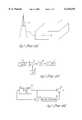
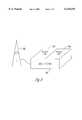
- the power amplifier of broadcast transmission equipmentsuch as the wireless base station 1 having antenna 2 illustrated in FIG. 1
- the power amplifieroperates in a non-linear fashion when the power amplifier is operated near its peak output.
- the power amplifierintroduces significant signal distortion, which can appear in various forms.
- signal distortiontaking the form of a degradation of the spectral components of the signal being amplified, it can also take the form of spurious spectral output outside of the bandwidth of the signal being amplified.
- FIG. 2illustrates a simplified block diagram of a typical base station transmitter operating with quadrature amplitude modulation (QAM).
- QAMquadrature amplitude modulation
- An in-phase component (I) and a quadrature component (Q) of baseband signal 6are combined with a local oscillator 10 signal in modulator 8 and the resulting up-converted radio frequency (RF) signal is applied to the high power amplifier (HPA) 12.
- HPA 12amplifies the up-converted RF signal for transmission by antenna 2.
- a broadcast system employing QAMrequires the transmitter to vary both the phase and amplitude of the transmitted signal.
- a power amplifier that performs non-linearly as it approaches its peak outputgenerally has significant difficulty in implementing the QAM scheme, so that as a result spurious emissions are often transmitted out of an assigned RF channel, contrary to required industry standards and governmental regulations.
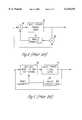
- FIG. 3illustrates a block diagram of a high power amplifier (HPA) employing a feed forward linearization technique.
- the input to basic power module (BPM) 15 and the output of BPM 15are both fed into a comparison circuit 16, which generates a difference output to error amplifier 20.
- the output of error amplifier 20is applied to summing circuit 18, to which is also applied the BPM output.
- the BPM outputis thus modified in response to differences in the content of the signal going into the BPM and that of the signal coming out of the BPM.
- FIG. 4illustrates a block diagram of a high power amplifier (HPA) employing a feedback linearization technique.
- HPAhigh power amplifier
- the input to BPM 15 and the output of BPM 15are both fed into a multiplier circuit 26, which generates an output to an analog processing circuit 28.
- the output of analog processing circuit 28is applied to multiplier circuit 24, to which is also applied the signal which is to be amplified by BPM 15.
- the output of multiplier circuit 24is input into BPM 15. Accordingly, the output of BPM 15 is modified in response to differences in the content of the signal going into BPM 15 and that of the signal coming out of BPM 15.
- FIGS. 3 and 4require very expensive equipment to implement, in that among other things they require high performance analog circuitry that must be properly adjusted by skilled labor and which may subsequently go out of adjustment.
- predistortion linearizationIt is well known to reduce intermodulation distortion in power amplifiers by predistorting the signal to be amplified in order to cancel out the distortion that is produced by the amplifier.
- predistortion linearizationOne type of predistortion employed in the art utilizes predistortion linearization, which will now be discussed briefly.
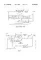
- FIG. 5illustrates a block diagram of a high power amplifier (HPA) employing a predistortion linearization technique.
- HPAhigh power amplifier
- the signal to be amplified by the HPAis fed into a module 30 which functions according to an inverse model of the signal distortion characteristics of BPM 15.
- the signal to be amplified by the BPM 15is also fed into a digital processing circuit 32 along with the output of the BPM 15.
- the output of the digital processing circuit 32is coupled to module 30, whose output is coupled to the BPM 15.
- the output of BPM 15is modified in response to differences in the content of the signal going into the BPM 15 and that of the signal coming out of the BPM 15.
- FIG. 6illustrates a block diagram of a high power amplifier (HPA) employing an instantaneous predistortion linearization technique without memory.
- HPAhigh power amplifier
- the signal to be amplified by the HPAis fed into an inverse distortion or predistortion module 40 which performs inverse distortion or predistortion of the signal in an attempt to cancel out the non-linear signal transfer characteristics of BPM 15.
- the signal to be amplified by the BPM 15is also fed into a digital processing circuit 42 along with the output of the BPM 15.
- the digital processing circuit 42generates model parameters in the form of a description 44 of an amplitude function based on adaptive parameters and a description 46 of a phase function based on adaptive parameters.
- the outputs of blocks 44 and 46are coupled to module 40, whose output is coupled to the BPM 15.
- the output of BPM 15is modified in response to differences in the content of the signal going into the BPM 15 and that of the signal coming out of the BPM 15.
- the technique of using instantaneous predistortion linearization without memorysuffers from an inability to track relatively quick changes in the ambient environment of the HPA, such as heating of the BPM due to relatively quick changes in the average power of the input signal, and to track changes in the bias conditions of the BPM due to relatively quick changes in the average power of the input signal.
- U.S. Pat. No. 4,291,277describes the use of an adaptive predistortion technique for linearizing a power amplifier.
- Digital data to be transmittedis used to access digital codes representing in-phase (I) and quadrature (Q) reference voltages from a memory.
- the digital codesare processed into a composite signal in the intermediate frequency range and input into the amplifier for transmission.
- Part of the amplifier outputis fed back to a comparator network to be compared with the I and Q reference voltages, and any differences between the I and Q outputs of the amplifier and the respective reference voltages are summed with the I and Q components read out of the memory and are written into the memory as updated predistorted I and Q components.
- U.S. Pat. No. 5,148,448describes an adaptive predistortion circuit for predistorting input data before it goes into the amplifier.
- the predistortion circuitincludes a memory which is continually updated by the results of a comparison of the input data and the amplifier output.
- U.S. Pat. No. 5,870,668describes an amplifier having distortion compensation and a base station for radio communication using such amplifier.
- the amplifierincludes a coefficient-generating circuit for generating compensation coefficients to compensate for distortion characteristics of the amplifier.
- the coefficient-generating circuitis responsive to an error signal, generated in response to comparing the input signal with an output signal of the amplifier, based upon an adaptive algorithm.
- an amplifierhaving an input and an output, the amplifier comprising a power module coupled to the output, a predistortion module coupled to the input and to the power module, an amplifier gain model coupled to the input and to the predistortion module, and a parameter generator coupled to the input, to the output, and to the amplifier gain module.
- the parameter generatorcomprises a Kalman filter.
- the amplifier gain modelcomprises a polynomial function of the power module gain function and a time constant.
- a base stationwhich includes the amplifier having the features and advantages described above.
- FIG. 1illustrates a typical wireless base station
- FIG. 2illustrates a simplified block diagram of a typical base station transmitter operating with QAM
- FIG. 3illustrates a block diagram of a high power amplifier (HPA) employing a feed forward linearization technique
- FIG. 4illustrates a block diagram of a high power amplifier (HPA) employing a feedback linearization technique
- FIG. 5illustrates a block diagram of a high power amplifier (HPA) employing a predistortion linearization technique
- FIG. 6illustrates a block diagram of a high power amplifier (HPA) employing an instantaneous predistortion linearization technique without memory;
- HPAhigh power amplifier
- FIG. 7illustrates a block diagram of a high power amplifier (HPA) employing a predistortion linearization technique with memory, in accordance with a preferred embodiment of the present invention
- FIG. 8shows a flow diagram of a method for operating a high power amplifier (HPA) employing a predistortion linearization technique with memory, in accordance with a preferred embodiment of the present invention.
- HPAhigh power amplifier
- FIG. 9illustrates a wireless base station comprising a high power amplifier (HPA) employing a predistortion linearization technique with memory, in accordance with a preferred embodiment of the present invention.
- HPAhigh power amplifier
- FIG. 7illustrates a block diagram of a high power amplifier (HPA) 103 employing a predistortion linearization technique with memory, in accordance with a preferred embodiment of the present invention.
- HPAhigh power amplifier
- amplifier 103comprises an input terminal 51 and an output terminal 59.
- the amplifierfurther includes a basic power module (BPM) 15 which generates the amplifier's output at output terminal 59.
- BPM 15can be any suitable commercially available power amplifier. In a preferred embodiment it is a fixed gain power amplifier. BPM 15 contributes significant distortion to the amplified output signal when BPM 15 is operating at or near its peak output.
- Amplifier 103also includes a parameter generator 50 coupled to input terminal 51 and to output terminal 59.
- Parameter generator 50generates model parameters over line 52 in response to differences between the input signal and the output signal.
- the model parametersare coupled via line 52 to an amplifier gain model 60.
- Amplifier gain model 60is coupled to the amplifier input 51 via a calculation module 58, which calculates the instantaneous input signal power q and generates the result to amplifier gain model 60.
- Amplifier gain model 60generates distortion compensating values over line 61 to predistortion module 54.
- Predistortion module 54is coupled to the input terminal 51 and to BPM 15. Predistortion module 54 performs the function of combining the input signal with the distortion compensating values received from amplifier gain model 60 to produce a predistorted input signal over line 55 to BPM 15. BPM 15 amplifies the predistorted input signal, applying its own distortion characteristics, and the resultant output signal from BPM 15 is an amplified signal with substantially all distortion removed.
- the amplifier gain model 60will now be discussed in greater detail.
- the gain function of BPM 15is provided by the manufacturer or can be determined by appropriate measurements.
- the amplifier gain model 60comprises a polynomial function of the BPM 15 gain function and a time constant.
- the amplifier gain modelis represented by the equation:
- G(q(t))is the transfer gain matrix of the BPM given by Equation 2 as follows: ##EQU1## Wherein x is the convolution operator.
- Coefficients G 0 , G 1 , G 2 , G 3 , G 4 , and time constant "a"are model parameters generated by parameter generator 50.
- Equation 2is the input power to the power module and is represented by:
- Xis the input signal complex vector represented by: ##EQU2## wherein X r is the real component of the input signal and X i is the imaginary component of the input signal,
- Yis the output signal complex vector represented by: ##EQU3## wherein Y r is the real component of the output signal and Y i is the imaginary component of the output signal.
- parameter generator 50is implemented as a Kalman filter.
- the Kalman filter used in parameter generator 50is well known in the art and can be defined as an optimum recursive filter that operates on the basis of least squares approximation.
- the Kalman filtercontains a dynamic model of system errors, characterized as a set of first order linear differential equations.
- the Kalman filterthus comprises equations in which the state-variables correspond to respective error sources, and the equations express the dynamic relationship between these error sources. Weighting factors can be applied to take account of the relative contributions of the errors.
- the Kalman filterconstantly reassesses the values of the state-variables (in this case, the parameters G 0 , G 1 , G 2 , G 3 , G 4 , and "a") as it receives new measured values, simultaneously taking all past measurements into account. Therefore, the Kalman filter is able to predict a value for the model parameters based on a set of state-variables which are updated recursively from the respective input and output signals. Kalman filters have been shown to be the optimal linear estimator in the least squares sense for estimating dynamic system states in linear systems.
- calculation module 58can be implemented in any suitable way by one of ordinary skill, either with special purpose hardware or a program-controlled general purpose processor.
- FIG. 8shows a flow diagram of a method for operating a high power amplifier (HPA) employing a predistortion linearization technique with memory, in accordance with a preferred embodiment of the present invention.
- HPAhigh power amplifier
- the processbegins in box 70.
- the amplifier gain model 60is based upon a polynomial function of the BPM 15 gain function and a time constant "a".
- the input signal and output signalare provided to the parameter generator 50.
- the parameter generator 50is operated as a Kalman filter, and model parameters are generated.
- the model parametersare provided to the amplifier gain model 60.
- the input power level of the input signal into amplifier 103is determined, and the result is provided to the amplifier gain model 60.
- distortion compensating valuesare generated by the amplifier gain model 60, using the model parameters and the input power level.
- the distortion compensating valuesare combined with the input signal to generate a predistorted input signal.
- the predistorted input signalis provided to the BPM 15.
- the BPM 15amplifies the predistorted input signal and provides an amplified signal at the amplifier 103 output.
- the amplified signalis provided to antenna 102 for broadcast.
- FIG. 8illustrates the method as ending in box 90, it will be understood by those skilled in the art that the appropriate steps in FIG. 8 will be iterated repeatedly to carry out the method of operating a power amplifier. It will also be understood that the steps of the method can be carried out in any appropriate order and need not be executed in the order described with reference to FIG. 8.
- FIG. 9illustrates a wireless base station 101 comprising a power amplifier employing a predistortion linearization technique with memory, in accordance with a preferred embodiment of the present invention.
- wireless base station 101comprises at least one power amplifier 103 of the type illustrated in FIG. 7.
- Wireless base station 101can comprise, if needed, a plurality of additional power amplifiers, such as power amplifier 104.
- wireless base station 101comprises a suitable antenna 102.
- wireless base stationcomprises equipment suitable for sending and receiving Code Division Multiple Access (CDMA) communications.
- CDMACode Division Multiple Access
- wireless base station 101can be used for providing wireless communications in any desired manner and for any type of wireless communications protocol or standard.
- the present inventionprovides an amplifier which operates in substantially linear fashion near its maximum output and which is relatively inexpensive to implement.
- a wireless base stationcomprising an amplifier which operates in substantially linear fashion near its maximum output and which is relatively inexpensive to implement.
- BPMbasic power modules
Landscapes
- Physics & Mathematics (AREA)
- Nonlinear Science (AREA)
- Engineering & Computer Science (AREA)
- Power Engineering (AREA)
- Amplifiers (AREA)
Abstract
Description
Y(t)=G(q(t))X(t) [Equation 1]
q=x.sub.r.sup.2 +x.sub.i.sup.2 [Equation 3]
Claims (17)
Y(t)=G(q(t))X(t)
q=x.sub.r.sup.2 +x.sub.i.sup.2
Y(t)=G(q(t))X(t)
q=x.sub.r.sup.2 +x.sub.i.sup.2
Y(t)=G(q(t))X(t)
q=x.sub.r.sup.2 +x.sub.i.sup.2
Y(t)=G(q(t))X(t)
q=x.sub.r.sup.2 +x.sub.i.sup.2
Y(t)=G(q(t))X(t)
q=x.sub.r.sup.2 +x.sub.i.sup.2
Y(t)=G(q(t))X(t)
q=x.sub.r.sup.2 +x.sub.i.sup.2
Priority Applications (1)
| Application Number | Priority Date | Filing Date | Title |
|---|---|---|---|
| US09/306,607US6118335A (en) | 1999-05-06 | 1999-05-06 | Method and apparatus for providing adaptive predistortion in power amplifier and base station utilizing same |
Applications Claiming Priority (1)
| Application Number | Priority Date | Filing Date | Title |
|---|---|---|---|
| US09/306,607US6118335A (en) | 1999-05-06 | 1999-05-06 | Method and apparatus for providing adaptive predistortion in power amplifier and base station utilizing same |
Publications (1)
| Publication Number | Publication Date |
|---|---|
| US6118335Atrue US6118335A (en) | 2000-09-12 |
Family
ID=23186056
Family Applications (1)
| Application Number | Title | Priority Date | Filing Date |
|---|---|---|---|
| US09/306,607Expired - LifetimeUS6118335A (en) | 1999-05-06 | 1999-05-06 | Method and apparatus for providing adaptive predistortion in power amplifier and base station utilizing same |
Country Status (1)
| Country | Link |
|---|---|
| US (1) | US6118335A (en) |
Cited By (45)
| Publication number | Priority date | Publication date | Assignee | Title |
|---|---|---|---|---|
| US6377116B1 (en)* | 2000-05-08 | 2002-04-23 | Iowa State University Research Foundation, Inc. | Pre-distorter and corresponding method for deriving same |
| WO2002095932A1 (en)* | 2001-05-18 | 2002-11-28 | Spectrian Corporation | Digitally implemented predistorter control mechanism for linearizing high efficiency rf power amplifiers |
| US20020193087A1 (en)* | 2001-06-07 | 2002-12-19 | Jaehyeong Kim | Method and apparatus for modeling and estimating the characteristics of a power amplifier |
| KR100366289B1 (en)* | 2000-12-23 | 2002-12-31 | 한국전자통신연구원 | Predistorter design and method using stochastic gradient method and indirect learning architecture |
| WO2003043182A1 (en)* | 2001-11-12 | 2003-05-22 | Telefonaktiebolaget Lm Ericsson | Non-linear modeling method |
| US6577192B2 (en)* | 1999-05-28 | 2003-06-10 | Fujitsu Limited | Predistortion-type distortion compensation amplifying apparatus |
| US20030133404A1 (en)* | 2002-01-11 | 2003-07-17 | Mitsubishi Denki Kabushiki Kaisha | Pre-distortion method for telecommunication system and transmitter for mobile terminal of MC-CDMA telecommunication system |
| US20030133403A1 (en)* | 2002-01-11 | 2003-07-17 | Mitsubishi Denki Kabushiki Kaisha | Pre-distortion method for telecommunication system and transmitter for mobile terminal of MC-CDMA telecommunication system |
| US20040136470A1 (en)* | 2003-01-15 | 2004-07-15 | Andrew Corporation | Uncorrelated adaptive predistorter |
| US20050017801A1 (en)* | 2003-07-23 | 2005-01-27 | Andrew Corporation | Elimination of peak clipping and improved efficiency for RF power amplifiers with a predistorter |
| US20050024138A1 (en)* | 2003-07-31 | 2005-02-03 | Andrew Corporation | Predistorter for phase modulated signals with low peak to average ratios |
| US20050073360A1 (en)* | 2003-10-06 | 2005-04-07 | Andrew Corporation | Architecture and implementation methods of digital predistortion circuitry |
| US20050157814A1 (en)* | 2004-01-21 | 2005-07-21 | Armando Cova | Wideband enhanced digital injection predistortion system and method |
| US20050163249A1 (en)* | 2004-01-27 | 2005-07-28 | Crestcom, Inc. | Predistortion circuit and method for compensating linear distortion in a digital RF communications transmitter |
| US20050163205A1 (en)* | 2004-01-27 | 2005-07-28 | Crestcom, Inc. | Equalized signal path with predictive subtraction signal and method therefor |
| US20050163250A1 (en)* | 2004-01-27 | 2005-07-28 | Crestcom, Inc. | Distortion-managed digital RF communications transmitter and method therefor |
| US20050163252A1 (en)* | 2004-01-27 | 2005-07-28 | Crestcom, Inc. | Transmitter predistortion circuit and method therefor |
| US20050163268A1 (en)* | 2004-01-27 | 2005-07-28 | Crestcom, Inc. | Predistortion circuit and method for compensating nonlinear distortion in a digital RF communications transmitter |
| US20050163251A1 (en)* | 2004-01-27 | 2005-07-28 | Crestcom, Inc. | Predistortion circuit and method for compensating A/D and other distortion in a digital RF communications transmitter |
| US20050163208A1 (en)* | 2004-01-27 | 2005-07-28 | Crestcom, Inc. | Equalized signal path with predictive subtraction signal and method therefor |
| US20050190857A1 (en)* | 2004-03-01 | 2005-09-01 | Braithwaite Richard N. | Digital predistortion system and method for linearizing an RF power amplifier with nonlinear gain characteristics and memory effects |
| US20050195919A1 (en)* | 2004-03-03 | 2005-09-08 | Armando Cova | Digital predistortion system and method for high efficiency transmitters |
| US6950194B2 (en) | 2001-12-07 | 2005-09-27 | Micronic Laser Systems Ab | Alignment sensor |
| US6972622B2 (en) | 2003-05-12 | 2005-12-06 | Andrew Corporation | Optimization of error loops in distributed power amplifiers |
| US20060022751A1 (en)* | 2004-07-28 | 2006-02-02 | Fuller Arthur T G | Power amplifier arrangement and method for memory correction/linearization |
| US7085330B1 (en) | 2002-02-15 | 2006-08-01 | Marvell International Ltd. | Method and apparatus for amplifier linearization using adaptive predistortion |
| US20070116100A1 (en)* | 2005-11-21 | 2007-05-24 | Telefonaktiebolaget Lm Ericsson (Publ) | Simplified generalized rake receiver method and apparatus |
| US20080014866A1 (en)* | 2006-07-12 | 2008-01-17 | Lipowski Joseph T | Transceiver architecture and method for wireless base-stations |
| US7362821B1 (en) | 2002-05-22 | 2008-04-22 | Marvel International Ltd. | Method and apparatus for amplifier linearization using adaptive predistortion |
| US20080144709A1 (en)* | 2006-12-19 | 2008-06-19 | Crestcom, Inc. | RF transmitter with predistortion and method therefor |
| US20080285640A1 (en)* | 2007-05-15 | 2008-11-20 | Crestcom, Inc. | RF Transmitter With Nonlinear Predistortion and Method Therefor |
| US7486722B2 (en) | 2001-04-18 | 2009-02-03 | Bae Systems Information And Electronic Systems Integration Inc. | Bandwidth efficient cable network modem |
| US20090124218A1 (en)* | 2007-11-14 | 2009-05-14 | Crestcom, Inc. | RF Transmitter with Heat Compensation and Method Therefor |
| US20090195309A1 (en)* | 2006-06-08 | 2009-08-06 | Kabushiki Kaisha Toshiba | Distortion compensator apparatus, amplifier apparatus, transmitter, and method of compensating distortion |
| WO2010055161A1 (en) | 2008-11-17 | 2010-05-20 | Nujira Limited | Generation of pre-distortion coefficients |
| US7729668B2 (en) | 2003-04-03 | 2010-06-01 | Andrew Llc | Independence between paths that predistort for memory and memory-less distortion in power amplifiers |
| US20110204975A1 (en)* | 2010-02-25 | 2011-08-25 | Fujitsu Limited | Calculating apparatus, distortion correcting apparatus, amplifying apparatus, and calculating method |
| US20120092067A1 (en)* | 2009-03-09 | 2012-04-19 | Zte Wistron Telecom Ab | Method and apparatus for linearizing a non-linear power amplifier |
| US20120108189A1 (en)* | 2010-11-02 | 2012-05-03 | Crestcom, Inc. | Transmitter Linearized Using Bias Deviation Gain Adjustment And Method Therefor |
| US8498591B1 (en) | 2009-08-21 | 2013-07-30 | Marvell International Ltd. | Digital Predistortion for nonlinear RF power amplifiers |
| US8699620B1 (en) | 2010-04-16 | 2014-04-15 | Marvell International Ltd. | Digital Predistortion for nonlinear RF power amplifiers |
| US8976896B2 (en) | 2010-11-02 | 2015-03-10 | Crestcom, Inc. | Transmitter linearized in response to derivative signal and method therefor |
| US9160586B1 (en) | 2013-07-24 | 2015-10-13 | Marvell International Ltd. | Method and apparatus for estimating and compensating for in-phase and quadrature (IQ) mismatch in a receiver of a wireless communication device |
| CN110765720A (en)* | 2019-09-12 | 2020-02-07 | 重庆大学 | Power amplifier predistortion method of complex value assembly line recurrent neural network model |
| US10637484B2 (en) | 2018-07-10 | 2020-04-28 | Seiko Epson Corporation | Circuit device, oscillator, clock signal generator, electronic apparatus, and vehicle |
Citations (6)
| Publication number | Priority date | Publication date | Assignee | Title |
|---|---|---|---|---|
| US4291277A (en)* | 1979-05-16 | 1981-09-22 | Harris Corporation | Adaptive predistortion technique for linearizing a power amplifier for digital data systems |
| US5148448A (en)* | 1989-03-14 | 1992-09-15 | U.S. Philips Corporation | Adaptive predistortion circuit with memory |
| US5870668A (en)* | 1995-08-18 | 1999-02-09 | Fujitsu Limited | Amplifier having distortion compensation and base station for radio communication using the same |
| US5892397A (en)* | 1996-03-29 | 1999-04-06 | Spectrian | Adaptive compensation of RF amplifier distortion by injecting predistortion signal derived from respectively different functions of input signal amplitude |
| US5929703A (en)* | 1996-08-07 | 1999-07-27 | Alcatel Telspace | Method and device for modeling AM-AM and AM-PM characteristics of an amplifier, and corresponding predistortion method |
| US5990738A (en)* | 1998-06-19 | 1999-11-23 | Datum Telegraphic Inc. | Compensation system and methods for a linear power amplifier |
- 1999
- 1999-05-06USUS09/306,607patent/US6118335A/ennot_activeExpired - Lifetime
Patent Citations (6)
| Publication number | Priority date | Publication date | Assignee | Title |
|---|---|---|---|---|
| US4291277A (en)* | 1979-05-16 | 1981-09-22 | Harris Corporation | Adaptive predistortion technique for linearizing a power amplifier for digital data systems |
| US5148448A (en)* | 1989-03-14 | 1992-09-15 | U.S. Philips Corporation | Adaptive predistortion circuit with memory |
| US5870668A (en)* | 1995-08-18 | 1999-02-09 | Fujitsu Limited | Amplifier having distortion compensation and base station for radio communication using the same |
| US5892397A (en)* | 1996-03-29 | 1999-04-06 | Spectrian | Adaptive compensation of RF amplifier distortion by injecting predistortion signal derived from respectively different functions of input signal amplitude |
| US5929703A (en)* | 1996-08-07 | 1999-07-27 | Alcatel Telspace | Method and device for modeling AM-AM and AM-PM characteristics of an amplifier, and corresponding predistortion method |
| US5990738A (en)* | 1998-06-19 | 1999-11-23 | Datum Telegraphic Inc. | Compensation system and methods for a linear power amplifier |
Cited By (74)
| Publication number | Priority date | Publication date | Assignee | Title |
|---|---|---|---|---|
| US6577192B2 (en)* | 1999-05-28 | 2003-06-10 | Fujitsu Limited | Predistortion-type distortion compensation amplifying apparatus |
| US6377116B1 (en)* | 2000-05-08 | 2002-04-23 | Iowa State University Research Foundation, Inc. | Pre-distorter and corresponding method for deriving same |
| KR100366289B1 (en)* | 2000-12-23 | 2002-12-31 | 한국전자통신연구원 | Predistorter design and method using stochastic gradient method and indirect learning architecture |
| US7486722B2 (en) | 2001-04-18 | 2009-02-03 | Bae Systems Information And Electronic Systems Integration Inc. | Bandwidth efficient cable network modem |
| WO2002095932A1 (en)* | 2001-05-18 | 2002-11-28 | Spectrian Corporation | Digitally implemented predistorter control mechanism for linearizing high efficiency rf power amplifiers |
| US20020193087A1 (en)* | 2001-06-07 | 2002-12-19 | Jaehyeong Kim | Method and apparatus for modeling and estimating the characteristics of a power amplifier |
| US6903604B2 (en)* | 2001-06-07 | 2005-06-07 | Lucent Technologies Inc. | Method and apparatus for modeling and estimating the characteristics of a power amplifier |
| WO2003043182A1 (en)* | 2001-11-12 | 2003-05-22 | Telefonaktiebolaget Lm Ericsson | Non-linear modeling method |
| US7091779B2 (en) | 2001-11-12 | 2006-08-15 | Telefonatiebolaget Lm Ericsson (Publ) | Non-linear modeling method |
| US20040257157A1 (en)* | 2001-11-12 | 2004-12-23 | Karl-Gosta Sahlman | Non-linear modeling method |
| US6950194B2 (en) | 2001-12-07 | 2005-09-27 | Micronic Laser Systems Ab | Alignment sensor |
| US7315529B2 (en)* | 2002-01-11 | 2008-01-01 | Mitsubishi Denki Kabushiki Kaisha | Pre-distortion method for telecommunication system and transmitter for mobile terminal of MC-CDMA telecommunication system |
| US7315530B2 (en)* | 2002-01-11 | 2008-01-01 | Mitsubishi Denki Kabushiki Kaisha | Pre-distortion method for telecommunication system and transmitter for mobile terminal of MC-CDMA telecommunication system |
| US20030133403A1 (en)* | 2002-01-11 | 2003-07-17 | Mitsubishi Denki Kabushiki Kaisha | Pre-distortion method for telecommunication system and transmitter for mobile terminal of MC-CDMA telecommunication system |
| US20030133404A1 (en)* | 2002-01-11 | 2003-07-17 | Mitsubishi Denki Kabushiki Kaisha | Pre-distortion method for telecommunication system and transmitter for mobile terminal of MC-CDMA telecommunication system |
| US7085330B1 (en) | 2002-02-15 | 2006-08-01 | Marvell International Ltd. | Method and apparatus for amplifier linearization using adaptive predistortion |
| US7535974B1 (en) | 2002-02-15 | 2009-05-19 | Marvell International Ltd. | Method and apparatus for amplifier linearization using adaptive predistortion |
| US7362821B1 (en) | 2002-05-22 | 2008-04-22 | Marvel International Ltd. | Method and apparatus for amplifier linearization using adaptive predistortion |
| US7403573B2 (en) | 2003-01-15 | 2008-07-22 | Andrew Corporation | Uncorrelated adaptive predistorter |
| US20040136470A1 (en)* | 2003-01-15 | 2004-07-15 | Andrew Corporation | Uncorrelated adaptive predistorter |
| US7729668B2 (en) | 2003-04-03 | 2010-06-01 | Andrew Llc | Independence between paths that predistort for memory and memory-less distortion in power amplifiers |
| US6972622B2 (en) | 2003-05-12 | 2005-12-06 | Andrew Corporation | Optimization of error loops in distributed power amplifiers |
| US20050017801A1 (en)* | 2003-07-23 | 2005-01-27 | Andrew Corporation | Elimination of peak clipping and improved efficiency for RF power amplifiers with a predistorter |
| US7259630B2 (en) | 2003-07-23 | 2007-08-21 | Andrew Corporation | Elimination of peak clipping and improved efficiency for RF power amplifiers with a predistorter |
| US20050024138A1 (en)* | 2003-07-31 | 2005-02-03 | Andrew Corporation | Predistorter for phase modulated signals with low peak to average ratios |
| US6963242B2 (en) | 2003-07-31 | 2005-11-08 | Andrew Corporation | Predistorter for phase modulated signals with low peak to average ratios |
| US20050073360A1 (en)* | 2003-10-06 | 2005-04-07 | Andrew Corporation | Architecture and implementation methods of digital predistortion circuitry |
| US7023273B2 (en) | 2003-10-06 | 2006-04-04 | Andrew Corporation | Architecture and implementation methods of digital predistortion circuitry |
| US7366252B2 (en) | 2004-01-21 | 2008-04-29 | Powerwave Technologies, Inc. | Wideband enhanced digital injection predistortion system and method |
| US20050157814A1 (en)* | 2004-01-21 | 2005-07-21 | Armando Cova | Wideband enhanced digital injection predistortion system and method |
| US20050163252A1 (en)* | 2004-01-27 | 2005-07-28 | Crestcom, Inc. | Transmitter predistortion circuit and method therefor |
| US20050163251A1 (en)* | 2004-01-27 | 2005-07-28 | Crestcom, Inc. | Predistortion circuit and method for compensating A/D and other distortion in a digital RF communications transmitter |
| US7099399B2 (en) | 2004-01-27 | 2006-08-29 | Crestcom, Inc. | Distortion-managed digital RF communications transmitter and method therefor |
| US20050163249A1 (en)* | 2004-01-27 | 2005-07-28 | Crestcom, Inc. | Predistortion circuit and method for compensating linear distortion in a digital RF communications transmitter |
| US20050163205A1 (en)* | 2004-01-27 | 2005-07-28 | Crestcom, Inc. | Equalized signal path with predictive subtraction signal and method therefor |
| US20050163250A1 (en)* | 2004-01-27 | 2005-07-28 | Crestcom, Inc. | Distortion-managed digital RF communications transmitter and method therefor |
| US7469491B2 (en) | 2004-01-27 | 2008-12-30 | Crestcom, Inc. | Transmitter predistortion circuit and method therefor |
| US7430248B2 (en) | 2004-01-27 | 2008-09-30 | Crestcom, Inc. | Predistortion circuit and method for compensating nonlinear distortion in a digital RF communications transmitter |
| US20050163268A1 (en)* | 2004-01-27 | 2005-07-28 | Crestcom, Inc. | Predistortion circuit and method for compensating nonlinear distortion in a digital RF communications transmitter |
| US7342976B2 (en) | 2004-01-27 | 2008-03-11 | Crestcom, Inc. | Predistortion circuit and method for compensating A/D and other distortion in a digital RF communications transmitter |
| US20050163208A1 (en)* | 2004-01-27 | 2005-07-28 | Crestcom, Inc. | Equalized signal path with predictive subtraction signal and method therefor |
| US7577211B2 (en) | 2004-03-01 | 2009-08-18 | Powerwave Technologies, Inc. | Digital predistortion system and method for linearizing an RF power amplifier with nonlinear gain characteristics and memory effects |
| US20050190857A1 (en)* | 2004-03-01 | 2005-09-01 | Braithwaite Richard N. | Digital predistortion system and method for linearizing an RF power amplifier with nonlinear gain characteristics and memory effects |
| US7336725B2 (en) | 2004-03-03 | 2008-02-26 | Powerwave Technologies, Inc. | Digital predistortion system and method for high efficiency transmitters |
| US20050195919A1 (en)* | 2004-03-03 | 2005-09-08 | Armando Cova | Digital predistortion system and method for high efficiency transmitters |
| US20060022751A1 (en)* | 2004-07-28 | 2006-02-02 | Fuller Arthur T G | Power amplifier arrangement and method for memory correction/linearization |
| US7095278B2 (en) | 2004-07-28 | 2006-08-22 | Nortel Networks Limited | Power amplifier arrangement and method for memory correction/linearization |
| US20070116100A1 (en)* | 2005-11-21 | 2007-05-24 | Telefonaktiebolaget Lm Ericsson (Publ) | Simplified generalized rake receiver method and apparatus |
| US20090195309A1 (en)* | 2006-06-08 | 2009-08-06 | Kabushiki Kaisha Toshiba | Distortion compensator apparatus, amplifier apparatus, transmitter, and method of compensating distortion |
| US8204454B2 (en)* | 2006-06-08 | 2012-06-19 | Kabushiki Kaisha Toshiba | Distortion compensator apparatus, amplifier apparatus, transmitter, and method of compensating distortion |
| US20080014866A1 (en)* | 2006-07-12 | 2008-01-17 | Lipowski Joseph T | Transceiver architecture and method for wireless base-stations |
| US7962174B2 (en)* | 2006-07-12 | 2011-06-14 | Andrew Llc | Transceiver architecture and method for wireless base-stations |
| US20080144709A1 (en)* | 2006-12-19 | 2008-06-19 | Crestcom, Inc. | RF transmitter with predistortion and method therefor |
| US7724840B2 (en) | 2006-12-19 | 2010-05-25 | Crestcom, Inc. | RF transmitter with predistortion and method therefor |
| US20080285640A1 (en)* | 2007-05-15 | 2008-11-20 | Crestcom, Inc. | RF Transmitter With Nonlinear Predistortion and Method Therefor |
| US7899416B2 (en) | 2007-11-14 | 2011-03-01 | Crestcom, Inc. | RF transmitter with heat compensation and method therefor |
| US20090124218A1 (en)* | 2007-11-14 | 2009-05-14 | Crestcom, Inc. | RF Transmitter with Heat Compensation and Method Therefor |
| WO2010055161A1 (en) | 2008-11-17 | 2010-05-20 | Nujira Limited | Generation of pre-distortion coefficients |
| US20120092067A1 (en)* | 2009-03-09 | 2012-04-19 | Zte Wistron Telecom Ab | Method and apparatus for linearizing a non-linear power amplifier |
| US8482349B2 (en)* | 2009-03-09 | 2013-07-09 | Zte Wistron Telecom Ab | Method and apparatus for linearizing a non-linear power amplifier |
| US9002302B1 (en) | 2009-08-21 | 2015-04-07 | Marvell International Ltd. | Digital Predistortion for nonlinear RF power amplifiers |
| US8498591B1 (en) | 2009-08-21 | 2013-07-30 | Marvell International Ltd. | Digital Predistortion for nonlinear RF power amplifiers |
| EP2362542A3 (en)* | 2010-02-25 | 2011-11-30 | Fujitsu Limited | Calculating apparatus, distortion correcting apparatus, amplifying apparatus, and calculating method |
| US8390375B2 (en)* | 2010-02-25 | 2013-03-05 | Fujitsu Limited | Calculating apparatus, distortion correcting apparatus, amplifying apparatus, and calculating method |
| US20110204975A1 (en)* | 2010-02-25 | 2011-08-25 | Fujitsu Limited | Calculating apparatus, distortion correcting apparatus, amplifying apparatus, and calculating method |
| US8699620B1 (en) | 2010-04-16 | 2014-04-15 | Marvell International Ltd. | Digital Predistortion for nonlinear RF power amplifiers |
| US8995572B1 (en) | 2010-04-16 | 2015-03-31 | Marvell International Ltd. | Digital Predistortion for nonlinear RF power amplifiers |
| US8489047B2 (en)* | 2010-11-02 | 2013-07-16 | Crestcom, Inc. | Transmitter linearized using bias deviation gain adjustment and method therefor |
| US20120108189A1 (en)* | 2010-11-02 | 2012-05-03 | Crestcom, Inc. | Transmitter Linearized Using Bias Deviation Gain Adjustment And Method Therefor |
| US8976896B2 (en) | 2010-11-02 | 2015-03-10 | Crestcom, Inc. | Transmitter linearized in response to derivative signal and method therefor |
| US9160586B1 (en) | 2013-07-24 | 2015-10-13 | Marvell International Ltd. | Method and apparatus for estimating and compensating for in-phase and quadrature (IQ) mismatch in a receiver of a wireless communication device |
| US10637484B2 (en) | 2018-07-10 | 2020-04-28 | Seiko Epson Corporation | Circuit device, oscillator, clock signal generator, electronic apparatus, and vehicle |
| CN110765720A (en)* | 2019-09-12 | 2020-02-07 | 重庆大学 | Power amplifier predistortion method of complex value assembly line recurrent neural network model |
| CN110765720B (en)* | 2019-09-12 | 2024-05-24 | 重庆大学 | Power amplifier predistortion method of complex-valued pipeline recurrent neural network model |
Similar Documents
| Publication | Publication Date | Title |
|---|---|---|
| US6118335A (en) | Method and apparatus for providing adaptive predistortion in power amplifier and base station utilizing same | |
| US7577211B2 (en) | Digital predistortion system and method for linearizing an RF power amplifier with nonlinear gain characteristics and memory effects | |
| US5959500A (en) | Model-based adaptive feedforward amplifier linearizer | |
| US7561636B2 (en) | Digital predistortion apparatus and method in power amplifier | |
| US7409007B1 (en) | Method and apparatus for reducing adjacent channel power in wireless communication systems | |
| US7020447B2 (en) | Method and apparatus for compensating for distortion in radio apparatus | |
| US7197085B1 (en) | Frequency-dependent magnitude pre-distortion for reducing spurious emissions in communication networks | |
| US6741663B1 (en) | Linearization method for amplifier, and amplifier arrangement | |
| US7366252B2 (en) | Wideband enhanced digital injection predistortion system and method | |
| EP0982849B1 (en) | Predistorter | |
| US5740520A (en) | Channel correction transceiver | |
| US7336725B2 (en) | Digital predistortion system and method for high efficiency transmitters | |
| US7418056B2 (en) | Digital predistorter using power series model | |
| US7106806B1 (en) | Reducing distortion of signals | |
| US7330517B2 (en) | Amplifier linearization using non-linear predistortion | |
| US20110096865A1 (en) | Digital predistortion transmitter | |
| US6711217B1 (en) | Apparatus and method for linearized power amplification | |
| US20040264597A1 (en) | Digital pre-distortion for the linearization of power amplifiers with asymmetrical characteristics | |
| KR100296982B1 (en) | Predistortion and Delay and Phase Difference Estimation Methods of Transmitter and Transmitted Signal and Feedback Signal in Mixed Linear and Nonlinear Distortion Systems | |
| US7266159B2 (en) | Frequency-dependent magnitude pre-distortion on non-baseband input signals for reducing spurious emissions in communication networks | |
| US7248642B1 (en) | Frequency-dependent phase pre-distortion for reducing spurious emissions in communication networks | |
| JP2001060883A (en) | Transmitter and data transmission device | |
| JP2002344249A (en) | Distortion compensating apparatus |
Legal Events
| Date | Code | Title | Description |
|---|---|---|---|
| AS | Assignment | Owner name:NORTEL NETWORKS CORPORATION, CANADA Free format text:ASSIGNMENT OF ASSIGNORS INTEREST;ASSIGNORS:NIELSEN, JORGEN S.;THOLL, DAVID M.;PAGE, TREVOR A.;REEL/FRAME:009944/0542 Effective date:19990504 | |
| STCF | Information on status: patent grant | Free format text:PATENTED CASE | |
| AS | Assignment | Owner name:NORTEL NETWORKS LIMITED, CANADA Free format text:CHANGE OF NAME;ASSIGNOR:NORTEL NETWORKS CORPORATION;REEL/FRAME:011195/0706 Effective date:20000830 Owner name:NORTEL NETWORKS LIMITED,CANADA Free format text:CHANGE OF NAME;ASSIGNOR:NORTEL NETWORKS CORPORATION;REEL/FRAME:011195/0706 Effective date:20000830 | |
| FPAY | Fee payment | Year of fee payment:4 | |
| FPAY | Fee payment | Year of fee payment:8 | |
| AS | Assignment | Owner name:ROCKSTAR BIDCO, LP, NEW YORK Free format text:ASSIGNMENT OF ASSIGNORS INTEREST;ASSIGNOR:NORTEL NETWORKS LIMITED;REEL/FRAME:027164/0356 Effective date:20110729 | |
| FPAY | Fee payment | Year of fee payment:12 | |
| AS | Assignment | Owner name:APPLE INC., CALIFORNIA Free format text:ASSIGNMENT OF ASSIGNORS INTEREST;ASSIGNOR:ROCKSTAR BIDCO, LP;REEL/FRAME:028602/0252 Effective date:20120511 |