US6117153A - Neovascularization catheter - Google Patents
Neovascularization catheterDownload PDFInfo
- Publication number
- US6117153A US6117153AUS09/123,758US12375898AUS6117153AUS 6117153 AUS6117153 AUS 6117153AUS 12375898 AUS12375898 AUS 12375898AUS 6117153 AUS6117153 AUS 6117153A
- Authority
- US
- United States
- Prior art keywords
- catheter
- cutting
- positioning
- lumen
- deployment
- Prior art date
- Legal status (The legal status is an assumption and is not a legal conclusion. Google has not performed a legal analysis and makes no representation as to the accuracy of the status listed.)
- Expired - Lifetime
Links
Images


Classifications
- A—HUMAN NECESSITIES
- A61—MEDICAL OR VETERINARY SCIENCE; HYGIENE
- A61B—DIAGNOSIS; SURGERY; IDENTIFICATION
- A61B17/00—Surgical instruments, devices or methods
- A61B17/32—Surgical cutting instruments
- A61B17/3205—Excision instruments
- A61B17/3207—Atherectomy devices working by cutting or abrading; Similar devices specially adapted for non-vascular obstructions
- A61B17/320725—Atherectomy devices working by cutting or abrading; Similar devices specially adapted for non-vascular obstructions with radially expandable cutting or abrading elements
- A—HUMAN NECESSITIES
- A61—MEDICAL OR VETERINARY SCIENCE; HYGIENE
- A61B—DIAGNOSIS; SURGERY; IDENTIFICATION
- A61B17/00—Surgical instruments, devices or methods
- A61B17/32—Surgical cutting instruments
- A61B17/320016—Endoscopic cutting instruments, e.g. arthroscopes, resectoscopes
- A61B17/32002—Endoscopic cutting instruments, e.g. arthroscopes, resectoscopes with continuously rotating, oscillating or reciprocating cutting instruments
- A—HUMAN NECESSITIES
- A61—MEDICAL OR VETERINARY SCIENCE; HYGIENE
- A61B—DIAGNOSIS; SURGERY; IDENTIFICATION
- A61B17/00—Surgical instruments, devices or methods
- A61B17/32—Surgical cutting instruments
- A61B17/3205—Excision instruments
- A61B17/3207—Atherectomy devices working by cutting or abrading; Similar devices specially adapted for non-vascular obstructions
- A61B17/320783—Atherectomy devices working by cutting or abrading; Similar devices specially adapted for non-vascular obstructions through side-hole, e.g. sliding or rotating cutter inside catheter
- A—HUMAN NECESSITIES
- A61—MEDICAL OR VETERINARY SCIENCE; HYGIENE
- A61B—DIAGNOSIS; SURGERY; IDENTIFICATION
- A61B17/00—Surgical instruments, devices or methods
- A61B17/00234—Surgical instruments, devices or methods for minimally invasive surgery
- A61B2017/00238—Type of minimally invasive operation
- A61B2017/00243—Type of minimally invasive operation cardiac
- A61B2017/00247—Making holes in the wall of the heart, e.g. laser Myocardial revascularization
- A61B2017/00252—Making holes in the wall of the heart, e.g. laser Myocardial revascularization for by-pass connections, i.e. connections from heart chamber to blood vessel or from blood vessel to blood vessel
- A—HUMAN NECESSITIES
- A61—MEDICAL OR VETERINARY SCIENCE; HYGIENE
- A61B—DIAGNOSIS; SURGERY; IDENTIFICATION
- A61B17/00—Surgical instruments, devices or methods
- A61B17/22—Implements for squeezing-off ulcers or the like on inner organs of the body; Implements for scraping-out cavities of body organs, e.g. bones; for invasive removal or destruction of calculus using mechanical vibrations; for removing obstructions in blood vessels, not otherwise provided for
- A61B2017/22038—Implements for squeezing-off ulcers or the like on inner organs of the body; Implements for scraping-out cavities of body organs, e.g. bones; for invasive removal or destruction of calculus using mechanical vibrations; for removing obstructions in blood vessels, not otherwise provided for with a guide wire
- A61B2017/22042—Details of the tip of the guide wire
- A61B2017/22044—Details of the tip of the guide wire with a pointed tip
- A—HUMAN NECESSITIES
- A61—MEDICAL OR VETERINARY SCIENCE; HYGIENE
- A61B—DIAGNOSIS; SURGERY; IDENTIFICATION
- A61B17/00—Surgical instruments, devices or methods
- A61B17/22—Implements for squeezing-off ulcers or the like on inner organs of the body; Implements for scraping-out cavities of body organs, e.g. bones; for invasive removal or destruction of calculus using mechanical vibrations; for removing obstructions in blood vessels, not otherwise provided for
- A61B2017/22051—Implements for squeezing-off ulcers or the like on inner organs of the body; Implements for scraping-out cavities of body organs, e.g. bones; for invasive removal or destruction of calculus using mechanical vibrations; for removing obstructions in blood vessels, not otherwise provided for with an inflatable part, e.g. balloon, for positioning, blocking, or immobilisation
- A61B2017/22065—Functions of balloons
- A61B2017/22069—Immobilising; Stabilising
- A—HUMAN NECESSITIES
- A61—MEDICAL OR VETERINARY SCIENCE; HYGIENE
- A61B—DIAGNOSIS; SURGERY; IDENTIFICATION
- A61B17/00—Surgical instruments, devices or methods
- A61B17/22—Implements for squeezing-off ulcers or the like on inner organs of the body; Implements for scraping-out cavities of body organs, e.g. bones; for invasive removal or destruction of calculus using mechanical vibrations; for removing obstructions in blood vessels, not otherwise provided for
- A61B2017/22072—Implements for squeezing-off ulcers or the like on inner organs of the body; Implements for scraping-out cavities of body organs, e.g. bones; for invasive removal or destruction of calculus using mechanical vibrations; for removing obstructions in blood vessels, not otherwise provided for with an instrument channel, e.g. for replacing one instrument by the other
- A—HUMAN NECESSITIES
- A61—MEDICAL OR VETERINARY SCIENCE; HYGIENE
- A61B—DIAGNOSIS; SURGERY; IDENTIFICATION
- A61B18/00—Surgical instruments, devices or methods for transferring non-mechanical forms of energy to or from the body
- A61B2018/00315—Surgical instruments, devices or methods for transferring non-mechanical forms of energy to or from the body for treatment of particular body parts
- A61B2018/00345—Vascular system
- A61B2018/00351—Heart
- A61B2018/00392—Transmyocardial revascularisation
Definitions
- the present inventionpertains generally to surgical devices and procedures. More particularly, the present invention pertains to a device and method for treating occlusions in the coronary artery which inhibit blood flow to the heart.
- stenotic segmentsmay partially or fully occlude the vessels, thereby decreasing cardiac capacity and/or causing myocardial infarction.
- angioplastygenerally involves inflation of a tubular balloon within the stenotic segments which occlude a particular vessel. Inflation of the balloon dilates the stenotic segment and fully or partially restores the flow of blood within the involved vessel.
- Atherectomyis another procedure which has been developed to clear stenotic segments from occluded vessels.
- a rotateable cutting toolis advanced through the stenotic segments which occlude a particular vessel.
- the rotating cuttersevers the material forming the stenotic segment, and allows the severed stenotic material to be removed by operation of a vacuum or other means.
- stenotic segmentscan develop in areas where angioplasty and atherectomy techniques can not be utilized.
- the development of a stenotic segments within a vessel which is internal to an organpresents special problems which may not be suited for treatment by traditional angioplasty and atherectomy procedures.
- stenotic segmentscan develop within the internal vessels of the heart. Because these vessels provide blood and oxygen to the myocardial tissue, occlusions which develop within these internal vessels present a serious risk to the health of the patient.
- the size and location of many of these vesselsmakes treatment with traditional methods and devices, such as angioplasty and atherectomy, difficult and generally ineffective.
- an object of the present inventionto provide a device and method for treating occlusions in the internal vessels of an organ. Another object of the present invention is to provide a device and method for treating an occlusion in a coronary artery which inhibits blood flow to the myocardial tissue of the heart. Still another object of the present invention is to provide a device for treating occlusions in the coronary artery which is relatively simple to manufacture, easy to use, and comparatively cost effective.
- the present inventionis direct to a device and method adapted for creating one or more new pathways from a vessel into an organ for the flow of blood. More specifically, the present invention is a device for creating one or more channels from the coronary artery into the cardiac muscle of the heart to enhance the flow of blood from the coronary artery into the cardiac muscle. This enhances cardiac capacity and inhibits myocardial infarction.
- the present inventionincludes a positioning catheter, anchoring means and a cutting catheter.
- the positioning catheteris formed with a deployment lumen.
- the deployment lumenincludes a plurality of deployment apertures which extend through the catheter into the deployment lumen.
- the anchor meanssecures the positioning catheter within the vessel around a circumference of the vessel, so that the cutting catheter can precisely create the perfusion channel.
- the anchor meansis a cylindrical sleeve attached to the positioning catheter.
- the sleevehas a distal sleeve end and a proximal sleeve end which are adapted to move relative to each other. Functionally, the movement of the distal sleeve end towards the proximal sleeve end causes the sleeve to expand radially outward.
- the anchor meansis an inflatable balloon attached to the positioning catheter.
- the cutting catheteris designed to incise and dilate the tissue of the cardiac muscle.
- the cutting catheterincludes a cutting catheter body having a plurality of spaced apart cutting blades.
- the bladesextend radially around the cutting catheter body and are aligned with the longitudinal axis of the cutting catheter body.
- the bladesmay be fixedly attached to the surface of the cutting catheter body or each blade may be retractable into the cutting catheter body.
- each bladeis preferably spring-loaded, or otherwise biased, to move from a first position where the blades are substantially contained within the cutting catheter to a second position where the blades extend from the surface of the cutting catheter body. This feature causes the blades to extend from the cutting catheter when the cutting catheter body extends from the positioning catheter.
- the cutting cathetermay be formed to include a cutting catheter lumen for receiving a cutting guidewire.
- the cutting guidewireis formed from a resilient and flexible metal, such as stainless steel, and has a sharpened distal end.
- the cutting guidewireis insertable through the cutting catheter lumen to allow the sharpened distal end of the cutting guidewire to be selectively extended from the cutting catheter.
- the cutting guidewirecan also be formed with a cutting guidewire lumen so that a medication can be released into the muscle.
- a contrast mediumcan be released from the cutting guidewire lumen and/or a pressure measurement can be taken with the cutting guidewire lumen to ensure that the cutting catheter is properly positioned in the cardiac muscle.
- the positioning catheteris first advanced into the coronary artery which supplies blood to the cardiac muscle.
- the advancement of the positioning cathetercontinues until a distal end of the positioning catheter is located within boundaries of the heart itself and the deployment aperture of the positioning catheter is located adjacent to the site where a new perfusion channel is to be formed.
- the anchoring meansis expanded to contact the artery to anchor the positioning catheter within the artery.
- the cutting guidewireis inserted through the deployment lumen and one of the deployment apertures into the myocardial tissue.
- a contrast mediumcan be released or a pressure measurement can be taken to ensure that the cutting guidewire is properly positioned.
- the cutting catheteris inserted into the deployment lumen over the cutting guidewire. This causes the blades to adopt the first position where each blade is positioned within the cutting catheter body.
- the cutting catheteris then advanced through the deployment lumen. As a distal end of the cutting catheter emerges from one of the deployment apertures, the spring-loaded blades adopt the second position where each blade extends from the surface of the cutting catheter body. Further, advancement of the cutting catheter and the cutting guidewire forces the cutting catheter to bore a channel through the myocardial tissue. The boring of the channel is aided by the blades which incise the myocardial tissue to accommodate the advancing cutting catheter.
- the cutting guidewiremay be advanced through the cutting catheter lumen in the myocardial tissue, thereby boring a path, or pilot hole, for subsequent advancement of the cutting catheter.
- the process of alternately advancing the cutting guidewire and cutting cathetermay be repeated until one or more channels through the myocardial tissue have reached the desired depth.
- the cutting cathetermay be removed from the patient and extended from an alternate deployment aperture into the myocardial tissue to create another perfusion channel.
- a vascular stentmay be advanced through the deployment lumen to be emitted at the orifice formed near the positioning catheter's distal end. As the stent leaves the orifice, it may be expanded to support the newly formed perfusion channel.
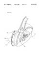
- FIG. 1is an isometric view of a device having features of the present invention
- FIG. 2is a cross-sectional view of the distal portion of the positioning catheter with a cutting catheter withdrawn and held within a deployment lumen;
- FIG. 3is a cross-sectional view of the positioning catheter illustrating an inflatable balloon shown in an expanded configuration and the cutting catheter advanced to project from the positioning catheter;
- FIG. 4is a cross-sectional view of the distal portion of the cutting catheter with the blades illustrated in a retracted position
- FIG. 5is a cross-sectional view of the cutting catheter with the blades illustrated in an extended position
- FIG. 6is a side plan view of the distal portion of another embodiment of a cutting catheter having features of the present invention.
- FIG. 7is a cross-sectional view of the distal portion of another embodiment of a device having features of the present invention.
- FIG. 8is a cross-sectional view of the embodiment illustrated in FIG. 7, with a cylindrical sleeve shown in an expanded configuration and the cutting catheter advanced to project from the positioning catheter;
- FIG. 9is a plan view of a device having features of the present invention shown operationally positioned within a cardiac vessel;
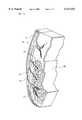
- FIG. 10is a perspective illustration of a human heart with an operational section of the heart illustrated away from the rest of the heart;
- FIG. 11is an enlarged, perspective of a device having features of the present invention positioned with the operational section of the heart from FIG. 10;
- FIG. 12is an enlarged, perspective view of the operational section of the heart from FIG. 10 after a procedure performed in accordance with the present invention.
- a device 10 having features of the present inventionincludes a positioning guidewire 11, a positioning catheter 12 and a cutting catheter 14.
- the positioning guidewire 11extends through a positioning guidewire lumen 15 in the positioning catheter 12.
- the positioning catheter 12is formed to have a cylindrical or otherwise elongated shape and has a distal end 16 and a proximal end 18.
- the positioning catheter 12is formed from a flexible and somewhat stiff material.
- the cutting catheter 14is also formed to have a cylindrical or otherwise elongated shape and has a distal end 20.
- the cutting catheter 14is formed from a flexible and somewhat resilient material.
- a series of blades 22are mounted substantially radially around the distal end 20 of the cutting catheter 14.
- FIG. 1also shows an anchor means 24 that is mounted to the distal end 16 of the positioning catheter 12.
- the positioning catheter 12is formed to surround an inflation lumen 26, a deployment lumen 28, and a bypass lumen 29.
- the inflation lumen 26passes between the distal end 16 and the proximal end 18 (shown in FIG. 1) of the positioning catheter 12.
- the inflation lumen 26is connected in fluid communication to the anchor means 24, i.e., an inflatable balloon.
- fluidmay be passed through the inflation lumen 26 from a pressurized fluid source (not shown) to selectively inflate the anchor means 24. Inflation of this nature may be appreciated by comparison of FIG. 2, where the balloon is shown in an uninflated state and of FIG. 3, where the balloon has been partially inflated.
- the deployment lumen 28extends between the proximal end 18 of the positioning catheter 12 toward the distal end 16 of the positioning catheter 12.
- a plurality of spaced apart deployment apertures 30are positioned near the distal end 16 of the positioning catheter 12.
- Each of the deployment apertures 30are oriented radially outward and distally from the positioning catheter 12.
- Each deployment aperture 30extends from a catheter outer surface 31 of the positioning catheter 12 into the deployment lumen 28.
- the embodiment illustrated in FIG. 1includes four (4) longitudinally, spaced apart deployment apertures 30. However, those skilled in the art should recognize that the number and space between adjacent deployment apertures 30 can be varied.
- the cutting catheter 14is advanced through the deployment lumen 28 until the distal end 20 of the cutting catheter 14 extends from one of the deployment apertures 30. Advancement of this nature may be appreciated by comparison of FIGS. 2 and 3. In more detail, it may be seen in FIG. 2, that the cutting catheter 14 is fully contained within the deployment lumen 28. In FIG. 3, however, the cutting catheter 14 has been advanced to project the distal end 20 of the cutting catheter 14 from one of the deployment apertures 30.
- the shape and orientation of the deployment apertures 30direct the cutting catheter 14 in a general direction which is radially outward and distally forward from the positioning catheter 12. It may be appreciated that the cutting catheter 14 may be advanced more or less than the advancement shown in FIG. 3. Further, it should be appreciated that once the anchor means 24 secures the positioning catheter 12, the cutting catheter 14 may be advanced from any one of the deployment apertures 30. Moreover, the distal end 20 of the cutting catheter 14 may be projected a variable and selectable distance from the positioning catheter 12. The projection of the cutting catheter 14 from the positioning catheter 12 is subsequently followed by the withdrawal of the cutting catheter 14 into the deployment lumen 28 of the positioning catheter 12.
- a radiopaque deployment marker 25(illustrated in FIG. 1) is positioned by each deployment aperture 30, so that the position of each deployment aperture 30 in the patient can be quickly evaluated. In the embodiment illustrated in FIG. 1, the deployment marker 25 encircles each deployment aperture 30.
- the bypass lumen 29allows for the flow of blood pass the anchor means.
- blood flow to and from the heartis not completely interrupted during this procedure.
- the bypass lumen 29extends through the anchor means 24 and into the positioning catheter 12.
- a pair of outlet apertures 33extend through the catheter outer surface 31 into the bypass lumen to allow for the flow of blood pass the anchor means 24.
- the cutting catheter 14includes a cutting catheter body 27 having a hollow chamber 32.
- a spring carrier 34is positioned inside the hollow chamber 32 and forms the mounting point for each of the blades 22.
- the spring carrier 34is attached to a projection 36 which is attached to the cutting catheter 14.
- the combination of the chamber 32, spring carrier 34, and projection 36allows each of the blades 22 to move between a first position (illustrated in FIG. 4) where the blades 22 are substantially contained within the chamber 32 and a second position (illustrated in FIG. 5) where the blades 22 project radially from the surface of the cutting catheter 14.
- the spring carrier 34is formed from a resilient material which biases the blades 22 to preferentially adopt the second or extended position. In this fashion, the blades 22 may be compressively retracted into the chamber 32, as shown in FIG. 4, to allow the cutting catheter 14 to advance through the deployment lumen 28. When the distal end 20 of the cutting catheter 14 is advanced to project from the deployment aperture 30, however, the blades 22 expand to adopt the second, or extended position of FIG. 5.
- each blade 22is formed to include a sloping rear shoulder 38.
- the sloping rear shoulder 38is shaped and dimensioned to engage the deployment aperture 30 when the cutting catheter 14 is withdrawn into the deployment lumen 28.
- the engagement between the sloping rear shoulder 38 and the deployment aperture 30applies a force to each blade 22 causing the blades 22 to adopt the first position, shown in FIG. 4, where the blades 22 are substantially contained within the chamber 32.
- the cutting catheter 14 of FIGS. 4 and 5provides a combined incisor/dilator which is adapted to advance through the deployment lumen 28. It may be appreciated, however, that other embodiments are possible for the cutting catheter 14.
- FIG. 6an alternate embodiment for the cutting catheter 14 is shown and designated 14'.
- the cutting catheter 14'is formed with a distal end 20' which is pointed and a plurality of spaced apart blades 22'.
- the blades 22'are fixed to distal end 20' and are not retractable, as was the case with blades 22 of cutting catheter 14. Instead, blades 22' are shaped and dimensioned to project from distal end 20' but not to exceed the width of cutting catheter 14'. In this way cutting catheter 14' may be advanced through deployment lumen 28 without danger of contact between blades 22' and deployment lumen 28.
- the present inventionalso includes a cutting guidewire 40.
- the cutting guidewire 40has a sharpened cutting guidewire tip 42 and is formed from a resilient and flexible material, such as stainless steel.
- the cutting catheter 14is formed to include a cutting catheter lumen 44 through which the cutting guidewire 40 may be inserted. This allows the cutting guidewire tip 42 of the cutting guidewire 40 to be selectively extended from the distal end 20 of the cutting catheter 14.
- the cutting guidewire 40can include a cutting guidewire lumen 45.
- the cutting guidewire lumen 45can be in fluid communication with a source of medication 66, a source of contrast medium 68, and/or a pressure sensor 70. This allows for medications or a contrast medium to be selectively released from the cutting guidewire tip 42. Further, it allows for pressure measurements to be taken at the cutting guidewire tip 42. With the pressure measurements, the location of the cutting guidewire tip 42 can be properly evaluated. This ensures that the cutting guidewire tip 42 is properly positioned prior to deploying the cutting catheter 14.
- the anchor means 24includes a cylindrical sleeve 46 which is attached to the distal end 16 of positioning catheter 12.
- Cylindrical sleeve 46is preferably formed from a wire mesh and has a distal sleeve end 48 and a proximal sleeve end 50.
- the proximal sleeve end 50is attached to the distal end 16 of positioning catheter 12.
- a grommet 52is attached to the distal sleeve end 48.
- the grommet 52is formed to allow for the passage of fluid through the cylindrical sleeve 46.
- the alternate embodiment for the positioning catheter 12is formed to include an actuator lumen 56 in place of the inflation lumen 26 of positioning catheter 12. Additionally, it may be seen that an actuator wire 58 passes through the actuator lumen 56 and connects to the grommet 52. In this embodiment, the positioning guidewire 11 extends through the positioning guidewire lumen 15 in the actuator wire 58.
- the actuator wire 58is movable in translation within the actuator lumen 56.
- the actuator wire 58may be utilized to move the grommet 52 translationally in line with the longitudinal axis of the positioning catheter 12. Translational movement of the grommet 52 causes translational movement of the distal sleeve end 48. In this fashion, the actuator wire 58 moves the distal sleeve end 48 translationally towards or translationally away from, the distal end 16 of the positioning catheter 12. Movement of this type may be visualized by comparison of FIG. 7 and FIG. 8. In particular, it may be seen in FIG. 8 that cylindrical sleeve 46 has a shorter overall length than cylindrical sleeve 46 shown in FIG. 7.
- FIGS. 7 and 8also shows that the decrease in overall length of the cylindrical sleeve 46, as shown in FIG. 8, is accompanied by a corresponding increase in the overall width of the cylindrical sleeve 46.
- the translational movement of the distal sleeve end 48 towards the distal end 16 of the positioning catheter 12has compressively expanded the cylindrical sleeve 46 of FIG. 8.
- the actuator wire 58may be manipulated to selectively expand the cylindrical sleeve 46.
- FIG. 9illustrates one embodiment of the device operationally positioned within a vessel 60.
- the anchor means 24is a balloon which is expanded to contact the circumference of the vessel 60 and anchor the positioning catheter 12 in the vessel 60.
- a perfusion channel 64is created in the tissue 62 with the cutting catheter 14.
- the perfusion channel 24is at an angle 71 of between approximately twenty degrees to eighty degrees (20°-80°) relative to a centerline 73 of the positioning catheter 12 proximate to where the cutting catheter 14 extends away from the positioning catheter 12.
- FIG. 10is an illustration of a human heart 72.
- An operational section 74 of the heart 72is illustrated away from the rest of the heart 72.
- the heartincludes a coronary artery 76, a ventricular cavity 80, and in this case a stenotic area 78.
- FIG. 11illustrates an enlarged view of the operational section 74 of the heart from in FIG. 10. Also, a device 10 having features of the present invention is shown operationally positioned in the coronary artery 76.
- FIG. 11illustrates that the anchor means 24 include the cylindrical sleeve 46 which is expanded to anchor the positioning catheter 12. Subsequently, a pair of perfusion channels 64 have been bored and created in the myocardial tissue 62 using the cutting catheter 14. As illustrated in FIG. 11, the perfusion channels 24 do not extend all the way through the myocardial tissue 62 into the cavity 80 of the heart 72. Instead, each perfusion channel 24 extends a distance of between approximately one centimeter to five centimeters (1.0 cm-5.0 cm), depending upon the angle of the perfusion channel 24. Further, each perfusion channel 24 has a width of between approximately two millimeters to three millimeters (2.0 mm-3.0 mm).
- FIG. 12illustrates the operational section 74 after the procedure has been performed and the device 10 has been removed. From FIG. 12, it is illustrated that perfusion channels 64 are supplying blood to the myocardial tissue 62. This allows the device 10 of the present invention to treat an occlusion 78 of the coronary artery 76 which restricts the blood flow to the myocardial tissue 62 of the heart 72. Thus, the coronary artery 76 is better able to supply blood to the myocardial tissue 62 and the heart 72 is able to function more efficiently.
- the positioning guidewire 11is inserted into a vessel 60.
- the particular arterial vessel 60 chosenwill be one that terminates within the myocardial tissue 62 and will generally be connected to a number of smaller vessels (not shown) some of which may be partially or fully occluded.
- the positioning catheter 12is inserted into the arterial vessel 60 over the positioning guidewire 11. The insertion or advancement of the positioning catheter 12 will continue until the distal end 16 and deployment apertures 30 of the positioning catheter 12 are adjacent to a target area where one or more perfusion channels 64 are to be established.
- the anchor means 24is expanded to anchor the distal end 16 of the positioning catheter 12 in the vessel 60.
- the cutting guidewire 40may be advanced through the deployment lumen 28.
- the cutting guidewire tip 42is controlled to exit from the desired deployment aperture 30.
- the cutting catheter 14is advanced through the deployment lumen 28 over the cutting guidewire 40. This causes the distal end 20 of the cutting catheter 14 to be projected from the deployment aperture 30 of the positioning catheter 12. As the cutting catheter 14 is projected from the deployment aperture 30, the distal end 20 of the cutting catheter 14 cuts a perfusion channel 64 in the myocardial tissue 62.
- the cutting of the perfusion channel 64is aided by the blades 22 which incise the myocardial tissue 62 and the cutting catheter body 27 which dilates the myocardial tissue 62.
- the cutting catheter 14may be withdrawn from the tissue 62 and rerouted through another deployment aperture 30 to create another perfusion channel 64.
- Advancement of the cutting catheter 14 through the myocardial tissue 62may be facilitated by use of the cutting guidewire 40.
- a pilot holemay be established through the myocardial tissue 62.
- the cutting catheter 14may then be advanced over the cutting guidewire 40 to enlarge the pilot hole into the perfusion channel 64.
- the process of advancing the cutting guidewire 40 followed by advancing the cutting catheter 14 over the cutting guidewire 40may be repeated until the perfusion channel 64 has reached the desired depth.
- each perfusion channel 64has a diameter between approximately two millimeters to three millimeters (2.0 mm-3.0 mm) and a depth of between approximately one centimeter to five centimeters (1.0 cm-5.0 cm), depending upon the angle of the perfusion channel 64. Further, as illustrated in FIG. 11, each perfusion channel 64 does not extend through the myocardial tissue 62 into the ventricular cavity 80. FIG. 12 illustrates that blood flow to the myocardial tissue 62 from the coronary artery 76 is enhanced by this procedure.
- medicationsuch as zylocaine, cardiac medications, and angiogenesis agents
- a contrast mediumcan be released from the cutting guidewire tip 42 to determine the location of the cutting guidewire tip 42. Further, pressure at the cutting guidewire tip 42 can be measured to determine whether the cutting guidewire tip 42 is in the proper location prior to inserting the cutting guidewire 40.
- a stent(not shown), or other prosthesis, to support the newly formed perfusion channel 64.
- the stentmay be advanced through the deployment lumen 28 and emitted through the deployment aperture 30 to be positioned by any method well known in the pertinent art.
Landscapes
- Health & Medical Sciences (AREA)
- Surgery (AREA)
- Life Sciences & Earth Sciences (AREA)
- Medical Informatics (AREA)
- Nuclear Medicine, Radiotherapy & Molecular Imaging (AREA)
- Engineering & Computer Science (AREA)
- Biomedical Technology (AREA)
- Heart & Thoracic Surgery (AREA)
- Vascular Medicine (AREA)
- Molecular Biology (AREA)
- Animal Behavior & Ethology (AREA)
- General Health & Medical Sciences (AREA)
- Public Health (AREA)
- Veterinary Medicine (AREA)
- Media Introduction/Drainage Providing Device (AREA)
- Surgical Instruments (AREA)
Abstract
Description
Claims (30)
Priority Applications (8)
| Application Number | Priority Date | Filing Date | Title |
|---|---|---|---|
| US09/123,758US6117153A (en) | 1996-10-03 | 1998-07-27 | Neovascularization catheter |
| CA002274032ACA2274032C (en) | 1998-07-27 | 1999-06-03 | Neovascularization catheter |
| EP99305216AEP0976363A3 (en) | 1998-07-27 | 1999-07-01 | Neovascularization catheter |
| ES99305216TES2144389T1 (en) | 1998-07-27 | 1999-07-01 | NEOVASCULARIZATION CATHETER. |
| DE0976363TDE976363T1 (en) | 1998-07-27 | 1999-07-01 | New vessel formation catheter |
| AU39165/99AAU741554B2 (en) | 1998-07-27 | 1999-07-12 | Neovascularization catheter |
| JP21014299AJP3720641B2 (en) | 1998-07-27 | 1999-07-26 | Device for drilling perfusion channels |
| US09/520,070US6296651B1 (en) | 1996-10-03 | 2000-03-07 | Method of using neovascularization catheter |
Applications Claiming Priority (2)
| Application Number | Priority Date | Filing Date | Title |
|---|---|---|---|
| US08/726,401US5800450A (en) | 1996-10-03 | 1996-10-03 | Neovascularization catheter |
| US09/123,758US6117153A (en) | 1996-10-03 | 1998-07-27 | Neovascularization catheter |
Related Parent Applications (1)
| Application Number | Title | Priority Date | Filing Date |
|---|---|---|---|
| US08/726,401Continuation-In-PartUS5800450A (en) | 1996-10-03 | 1996-10-03 | Neovascularization catheter |
Related Child Applications (1)
| Application Number | Title | Priority Date | Filing Date |
|---|---|---|---|
| US09/520,070DivisionUS6296651B1 (en) | 1996-10-03 | 2000-03-07 | Method of using neovascularization catheter |
Publications (1)
| Publication Number | Publication Date |
|---|---|
| US6117153Atrue US6117153A (en) | 2000-09-12 |
Family
ID=22410711
Family Applications (2)
| Application Number | Title | Priority Date | Filing Date |
|---|---|---|---|
| US09/123,758Expired - LifetimeUS6117153A (en) | 1996-10-03 | 1998-07-27 | Neovascularization catheter |
| US09/520,070Expired - LifetimeUS6296651B1 (en) | 1996-10-03 | 2000-03-07 | Method of using neovascularization catheter |
Family Applications After (1)
| Application Number | Title | Priority Date | Filing Date |
|---|---|---|---|
| US09/520,070Expired - LifetimeUS6296651B1 (en) | 1996-10-03 | 2000-03-07 | Method of using neovascularization catheter |
Country Status (7)
| Country | Link |
|---|---|
| US (2) | US6117153A (en) |
| EP (1) | EP0976363A3 (en) |
| JP (1) | JP3720641B2 (en) |
| AU (1) | AU741554B2 (en) |
| CA (1) | CA2274032C (en) |
| DE (1) | DE976363T1 (en) |
| ES (1) | ES2144389T1 (en) |
Cited By (41)
| Publication number | Priority date | Publication date | Assignee | Title |
|---|---|---|---|---|
| US20020052564A1 (en)* | 1998-03-03 | 2002-05-02 | Burbank Fred H. | Methods and apparatus for securing medical instruments to desired locations in a patient's body |
| US20030163148A1 (en)* | 2002-02-27 | 2003-08-28 | Lixiao Wang | Medical device |
| US6692458B2 (en)* | 2000-12-19 | 2004-02-17 | Edwards Lifesciences Corporation | Intra-pericardial drug delivery device with multiple balloons and method for angiogenesis |
| US20040143287A1 (en)* | 2003-01-21 | 2004-07-22 | Angioscore, Inc. | Apparatus and methods for treating hardened vascular lesions |
| US20040189412A1 (en)* | 2003-03-25 | 2004-09-30 | Murata Manufacturing Co., Ltd. | Temperature compensated piezoelectric oscillator and electronic device using the same |
| US20040215223A1 (en)* | 2003-04-25 | 2004-10-28 | Shaw William J. | Cutting stent and balloon |
| US20040243156A1 (en)* | 2003-05-29 | 2004-12-02 | Scimed Life Systems, Inc. | Cutting balloon catheter with improved balloon configuration |
| WO2004018016A3 (en)* | 2002-08-23 | 2005-01-13 | Medical Components Inc | Shielded tip catheter |
| US20050021070A1 (en)* | 2003-01-21 | 2005-01-27 | Angioscore, Inc. | Methods and apparatus for manipulating vascular prostheses |
| US20050026462A1 (en)* | 2003-07-30 | 2005-02-03 | Theodis Johnson | Relative rotation signal transfer assembly |
| US20050070888A1 (en)* | 2004-10-29 | 2005-03-31 | Boston Scientific Corporation | Medical device systems and methods |
| US20050137615A1 (en)* | 2003-12-19 | 2005-06-23 | Mapes Kenneth W. | Textured balloons |
| US20050149082A1 (en)* | 2003-12-31 | 2005-07-07 | Carl Yee | Microsurgical balloon with protective reinforcement |
| US20060111736A1 (en)* | 2004-11-23 | 2006-05-25 | Kelley Greg S | Serpentine cutting blade for cutting balloon |
| US20060247674A1 (en)* | 2005-04-29 | 2006-11-02 | Roman Ricardo D | String cutting balloon |
| US20060259005A1 (en)* | 2005-05-11 | 2006-11-16 | Angioscore, Inc. | Methods and systems for delivering substances into luminal walls |
| US7291158B2 (en) | 2004-11-12 | 2007-11-06 | Boston Scientific Scimed, Inc. | Cutting balloon catheter having a segmented blade |
| US20080281323A1 (en)* | 1999-01-27 | 2008-11-13 | Burbank Fred H | Tissue specimen isolating and damaging device and method |
| US20090105687A1 (en)* | 2007-10-05 | 2009-04-23 | Angioscore, Inc. | Scoring catheter with drug delivery membrane |
| US7566319B2 (en) | 2004-04-21 | 2009-07-28 | Boston Scientific Scimed, Inc. | Traction balloon |
| US7632288B2 (en) | 2003-05-12 | 2009-12-15 | Boston Scientific Scimed, Inc. | Cutting balloon catheter with improved pushability |
| US7754047B2 (en) | 2004-04-08 | 2010-07-13 | Boston Scientific Scimed, Inc. | Cutting balloon catheter and method for blade mounting |
| US7976557B2 (en) | 2004-06-23 | 2011-07-12 | Boston Scientific Scimed, Inc. | Cutting balloon and process |
| US7993358B2 (en) | 2005-02-11 | 2011-08-09 | Boston Scientific Scimed, Inc. | Cutting balloon catheter having increased flexibility regions |
| US8038691B2 (en) | 2004-11-12 | 2011-10-18 | Boston Scientific Scimed, Inc. | Cutting balloon catheter having flexible atherotomes |
| US8080026B2 (en) | 2003-01-21 | 2011-12-20 | Angioscore, Inc. | Apparatus and methods for treating hardened vascular lesions |
| US9173977B2 (en) | 2010-04-19 | 2015-11-03 | Angioscore, Inc. | Coating formulations for scoring or cutting balloon catheters |
| US20160081710A1 (en)* | 2014-09-18 | 2016-03-24 | Mayo Foundation For Medical Education And Research | Soft tissue cutting device and methods of use |
| US20160128855A1 (en)* | 2012-04-23 | 2016-05-12 | Pq Bypass, Inc. | Methods and systems for bypassing occlusions in a femoral artery |
| US9351756B2 (en) | 2010-09-21 | 2016-05-31 | Angioscore, Inc. | Method and system for treating valve stenosis |
| US9375328B2 (en) | 2001-11-09 | 2016-06-28 | Angioscore, Inc. | Balloon catheter with non-deployable stent |
| US10086178B2 (en) | 2001-11-09 | 2018-10-02 | Angioscore, Inc. | Balloon catheter with non-deployable stent |
| US10117668B2 (en) | 2013-10-08 | 2018-11-06 | The Spectranetics Corporation | Balloon catheter with non-deployable stent having improved stability |
| US10335189B2 (en) | 2014-12-03 | 2019-07-02 | PAVmed Inc. | Systems and methods for percutaneous division of fibrous structures |
| US10864055B2 (en) | 2017-10-13 | 2020-12-15 | Sonex Health, Inc. | Tray for a soft tissue cutting device and methods of use |
| USD989961S1 (en) | 2021-04-30 | 2023-06-20 | Sonex Health, Inc. | Soft tissue cutting device |
| US11937845B2 (en) | 2019-01-11 | 2024-03-26 | Mayo Foundation For Medical Education And Research | Micro-invasive surgical device and methods of use |
| US12004767B2 (en) | 2021-01-08 | 2024-06-11 | Sonex Health, Inc. | Surgical cutting device for ultrasonic guided soft tissue surgery |
| US12156693B2 (en) | 2020-05-27 | 2024-12-03 | PAVmed Inc. | Systems and methods for minimally-invasive division of fibrous structures |
| US12251122B2 (en) | 2021-04-30 | 2025-03-18 | Sonex Health, Inc. | Cutting device for trigger finger and other soft tissues |
| US12426939B2 (en) | 2019-05-29 | 2025-09-30 | Mayo Foundation For Medical Education And Research | Micro-invasive surgical device and methods of use |
Families Citing this family (17)
| Publication number | Priority date | Publication date | Assignee | Title |
|---|---|---|---|---|
| US6261304B1 (en) | 1998-09-10 | 2001-07-17 | Percardia, Inc. | Delivery methods for left ventricular conduit |
| US6196230B1 (en) | 1998-09-10 | 2001-03-06 | Percardia, Inc. | Stent delivery system and method of use |
| US7029450B2 (en) | 2001-12-14 | 2006-04-18 | Boston Scientific Scimed, Inc. | Dilation catheter assembly and related methods |
| JP3971320B2 (en) | 2003-02-17 | 2007-09-05 | 修 加藤 | catheter |
| EP1533146B1 (en)* | 2003-11-19 | 2008-09-03 | Siemens VDO Automotive Corporation | Asynchronous interleaving of RF signals |
| US7988670B2 (en)* | 2005-06-30 | 2011-08-02 | Tyco Healthcare Group Lp | Trocar assembly with rotatable obturator housing |
| US20070005087A1 (en)* | 2005-06-30 | 2007-01-04 | Smith Robert C | Thin bladed obturator with curved surfaces |
| GB0625936D0 (en)* | 2006-12-28 | 2007-02-07 | Thermoteknix Systems Ltd | Correction of non-uniformity of response in sensor arrays |
| JP5382938B2 (en) | 2007-02-20 | 2014-01-08 | コヴィディエン リミテッド パートナーシップ | Surgical instrument having an annular puncture device |
| JP5340638B2 (en) | 2007-05-22 | 2013-11-13 | コヴィディエン リミテッド パートナーシップ | Access sheath with blade |
| US20080300610A1 (en) | 2007-05-31 | 2008-12-04 | Cook Incorporated | Device for treating hardened lesions and method of use thereof |
| US20080319467A1 (en)* | 2007-06-22 | 2008-12-25 | Thomas Wenchell | Thin bladed obturator |
| US8911463B2 (en)* | 2008-06-10 | 2014-12-16 | Covidien Lp | Bladed/bladeless obturator for use in a surgical trocar assembly |
| US20110087258A1 (en)* | 2009-10-14 | 2011-04-14 | Sluss Robert K | Cannulated arthroscopic knife |
| US8372055B2 (en)* | 2009-10-27 | 2013-02-12 | Medtronic, Inc. | Method of using a deflectable subselecting catheter |
| US20110112623A1 (en)* | 2009-11-10 | 2011-05-12 | Schatz Richard A | System and Method for Placing a Coronary Stent at the Ostium of a Blood Vessel |
| JP6400826B2 (en)* | 2014-07-15 | 2018-10-03 | コーニンクレッカ フィリップス エヌ ヴェKoninklijke Philips N.V. | Device and method for intrahepatic shunt |
Citations (30)
| Publication number | Priority date | Publication date | Assignee | Title |
|---|---|---|---|---|
| US3512519A (en)* | 1967-10-26 | 1970-05-19 | Robert M Hall | Anatomical biopsy sampler |
| US3605721A (en)* | 1969-11-03 | 1971-09-20 | Ismet Hallac | Biopsy needle |
| US3990453A (en)* | 1973-04-25 | 1976-11-09 | Douvas Nicholas G | Apparatus for cataract surgery |
| US4195637A (en)* | 1977-10-21 | 1980-04-01 | Schneider Medintag Ag | Catheter arrangement, method of catheterization, and method of manufacturing a dilatation element |
| US4441509A (en)* | 1981-05-21 | 1984-04-10 | Sherwood Medical Company | Endometrial sampling device |
| US4582181A (en)* | 1983-08-12 | 1986-04-15 | Advanced Cardiovascular Systems, Inc. | Steerable dilatation catheter |
| US4589412A (en)* | 1984-01-03 | 1986-05-20 | Intravascular Surgical Instruments, Inc. | Method and apparatus for surgically removing remote deposits |
| US4690140A (en)* | 1986-04-01 | 1987-09-01 | John Mecca | Arterial regenerator |
| US4696667A (en)* | 1986-03-20 | 1987-09-29 | Helmut Masch | Intravascular catheter and method |
| US4708147A (en)* | 1985-02-25 | 1987-11-24 | Haaga John R | Universal biopsy needle |
| US4728319A (en)* | 1986-03-20 | 1988-03-01 | Helmut Masch | Intravascular catheter |
| US4757826A (en)* | 1985-05-01 | 1988-07-19 | Gazi Abdulhay | Endocervical biopsy instrument |
| US4765332A (en)* | 1986-07-14 | 1988-08-23 | Medinnovations, Inc. | Pullback atherectomy catheter system |
| US4887613A (en)* | 1987-11-23 | 1989-12-19 | Interventional Technologies Inc. | Cutter for atherectomy device |
| US4926858A (en)* | 1984-05-30 | 1990-05-22 | Devices For Vascular Intervention, Inc. | Atherectomy device for severe occlusions |
| US4966604A (en)* | 1989-01-23 | 1990-10-30 | Interventional Technologies Inc. | Expandable atherectomy cutter with flexibly bowed blades |
| WO1991008388A1 (en)* | 1989-11-24 | 1991-06-13 | Saab Automobile Aktiebolag | Arrangement for turbo regulation in an internal combustion engine |
| US5135484A (en)* | 1990-05-09 | 1992-08-04 | Pioneering Technologies, Inc. | Method of removing plaque from vessels |
| EP0551707A1 (en)* | 1992-01-13 | 1993-07-21 | Interventional Technologies Inc | Camming device for cutting tool |
| US5287861A (en)* | 1992-10-30 | 1994-02-22 | Wilk Peter J | Coronary artery by-pass method and associated catheter |
| US5312341A (en)* | 1992-08-14 | 1994-05-17 | Wayne State University | Retaining apparatus and procedure for transseptal catheterization |
| US5325860A (en)* | 1991-11-08 | 1994-07-05 | Mayo Foundation For Medical Education And Research | Ultrasonic and interventional catheter and method |
| US5372588A (en)* | 1992-11-24 | 1994-12-13 | Farley; Kevin | Trocar having blunt tip |
| EP0647434A2 (en)* | 1993-10-08 | 1995-04-12 | United States Surgical Corporation | Tissue piercing members |
| US5454782A (en)* | 1994-08-11 | 1995-10-03 | Perkins; Rodney C. | Translumenal circumferential energy delivery device |
| US5507795A (en)* | 1994-04-29 | 1996-04-16 | Devices For Vascular Intervention, Inc. | Catheter with perfusion system |
| EP0721766A1 (en)* | 1995-01-10 | 1996-07-17 | Interventional Technologies Inc | Vascular incisor/dilator |
| US5669920A (en)* | 1993-07-09 | 1997-09-23 | Devices For Vascular Intervention, Inc. | Atherectomy catheter |
| US5697944A (en)* | 1995-11-15 | 1997-12-16 | Interventional Technologies Inc. | Universal dilator with expandable incisor |
| US5800450A (en)* | 1996-10-03 | 1998-09-01 | Interventional Technologies Inc. | Neovascularization catheter |
Family Cites Families (8)
| Publication number | Priority date | Publication date | Assignee | Title |
|---|---|---|---|---|
| US5674232A (en)* | 1990-06-05 | 1997-10-07 | Halliburton; Alexander George | Catheter and method of use thereof |
| DE9190181U1 (en) | 1990-12-10 | 1993-07-29 | Howmedica Inc. (n.d.Ges.d.Staates Delaware), New York, N.Y. | Device for interstitial laser energy delivery |
| US6102046A (en)* | 1995-11-22 | 2000-08-15 | Arthrocare Corporation | Systems and methods for electrosurgical tissue revascularization |
| US5464395A (en)* | 1994-04-05 | 1995-11-07 | Faxon; David P. | Catheter for delivering therapeutic and/or diagnostic agents to the tissue surrounding a bodily passageway |
| US5769843A (en)* | 1996-02-20 | 1998-06-23 | Cormedica | Percutaneous endomyocardial revascularization |
| US5891133A (en)* | 1996-03-29 | 1999-04-06 | Eclipse Surgical Technologies, Inc. | Apparatus for laser-assisted intra-coronary transmyocardial revascularization and other applications |
| US5755714A (en)* | 1996-09-17 | 1998-05-26 | Eclipse Surgical Technologies, Inc. | Shaped catheter for transmyocardial revascularization |
| EP0984727A4 (en)* | 1996-11-08 | 2000-05-24 | Thomas J Fogarty | TRANSMYOCARDIAL VASCULARIZATION METHOD AND DEVICE |
- 1998
- 1998-07-27USUS09/123,758patent/US6117153A/ennot_activeExpired - Lifetime
- 1999
- 1999-06-03CACA002274032Apatent/CA2274032C/ennot_activeExpired - Fee Related
- 1999-07-01ESES99305216Tpatent/ES2144389T1/enactivePending
- 1999-07-01EPEP99305216Apatent/EP0976363A3/ennot_activeWithdrawn
- 1999-07-01DEDE0976363Tpatent/DE976363T1/enactivePending
- 1999-07-12AUAU39165/99Apatent/AU741554B2/ennot_activeCeased
- 1999-07-26JPJP21014299Apatent/JP3720641B2/ennot_activeExpired - Fee Related
- 2000
- 2000-03-07USUS09/520,070patent/US6296651B1/ennot_activeExpired - Lifetime
Patent Citations (30)
| Publication number | Priority date | Publication date | Assignee | Title |
|---|---|---|---|---|
| US3512519A (en)* | 1967-10-26 | 1970-05-19 | Robert M Hall | Anatomical biopsy sampler |
| US3605721A (en)* | 1969-11-03 | 1971-09-20 | Ismet Hallac | Biopsy needle |
| US3990453A (en)* | 1973-04-25 | 1976-11-09 | Douvas Nicholas G | Apparatus for cataract surgery |
| US4195637A (en)* | 1977-10-21 | 1980-04-01 | Schneider Medintag Ag | Catheter arrangement, method of catheterization, and method of manufacturing a dilatation element |
| US4441509A (en)* | 1981-05-21 | 1984-04-10 | Sherwood Medical Company | Endometrial sampling device |
| US4582181A (en)* | 1983-08-12 | 1986-04-15 | Advanced Cardiovascular Systems, Inc. | Steerable dilatation catheter |
| US4589412A (en)* | 1984-01-03 | 1986-05-20 | Intravascular Surgical Instruments, Inc. | Method and apparatus for surgically removing remote deposits |
| US4926858A (en)* | 1984-05-30 | 1990-05-22 | Devices For Vascular Intervention, Inc. | Atherectomy device for severe occlusions |
| US4708147A (en)* | 1985-02-25 | 1987-11-24 | Haaga John R | Universal biopsy needle |
| US4757826A (en)* | 1985-05-01 | 1988-07-19 | Gazi Abdulhay | Endocervical biopsy instrument |
| US4696667A (en)* | 1986-03-20 | 1987-09-29 | Helmut Masch | Intravascular catheter and method |
| US4728319A (en)* | 1986-03-20 | 1988-03-01 | Helmut Masch | Intravascular catheter |
| US4690140A (en)* | 1986-04-01 | 1987-09-01 | John Mecca | Arterial regenerator |
| US4765332A (en)* | 1986-07-14 | 1988-08-23 | Medinnovations, Inc. | Pullback atherectomy catheter system |
| US4887613A (en)* | 1987-11-23 | 1989-12-19 | Interventional Technologies Inc. | Cutter for atherectomy device |
| US4966604A (en)* | 1989-01-23 | 1990-10-30 | Interventional Technologies Inc. | Expandable atherectomy cutter with flexibly bowed blades |
| WO1991008388A1 (en)* | 1989-11-24 | 1991-06-13 | Saab Automobile Aktiebolag | Arrangement for turbo regulation in an internal combustion engine |
| US5135484A (en)* | 1990-05-09 | 1992-08-04 | Pioneering Technologies, Inc. | Method of removing plaque from vessels |
| US5325860A (en)* | 1991-11-08 | 1994-07-05 | Mayo Foundation For Medical Education And Research | Ultrasonic and interventional catheter and method |
| EP0551707A1 (en)* | 1992-01-13 | 1993-07-21 | Interventional Technologies Inc | Camming device for cutting tool |
| US5312341A (en)* | 1992-08-14 | 1994-05-17 | Wayne State University | Retaining apparatus and procedure for transseptal catheterization |
| US5287861A (en)* | 1992-10-30 | 1994-02-22 | Wilk Peter J | Coronary artery by-pass method and associated catheter |
| US5372588A (en)* | 1992-11-24 | 1994-12-13 | Farley; Kevin | Trocar having blunt tip |
| US5669920A (en)* | 1993-07-09 | 1997-09-23 | Devices For Vascular Intervention, Inc. | Atherectomy catheter |
| EP0647434A2 (en)* | 1993-10-08 | 1995-04-12 | United States Surgical Corporation | Tissue piercing members |
| US5507795A (en)* | 1994-04-29 | 1996-04-16 | Devices For Vascular Intervention, Inc. | Catheter with perfusion system |
| US5454782A (en)* | 1994-08-11 | 1995-10-03 | Perkins; Rodney C. | Translumenal circumferential energy delivery device |
| EP0721766A1 (en)* | 1995-01-10 | 1996-07-17 | Interventional Technologies Inc | Vascular incisor/dilator |
| US5697944A (en)* | 1995-11-15 | 1997-12-16 | Interventional Technologies Inc. | Universal dilator with expandable incisor |
| US5800450A (en)* | 1996-10-03 | 1998-09-01 | Interventional Technologies Inc. | Neovascularization catheter |
Cited By (100)
| Publication number | Priority date | Publication date | Assignee | Title |
|---|---|---|---|---|
| US7329228B2 (en)* | 1998-03-03 | 2008-02-12 | Senorx, Inc. | Methods and apparatus for securing medical instruments to desired locations in a patient's body |
| US7264596B2 (en)* | 1998-03-03 | 2007-09-04 | Senorx, Inc. | Methods and apparatus for securing medical instruments to desired locations in a patient's body |
| US20020052564A1 (en)* | 1998-03-03 | 2002-05-02 | Burbank Fred H. | Methods and apparatus for securing medical instruments to desired locations in a patient's body |
| US20060094983A1 (en)* | 1998-03-03 | 2006-05-04 | Burbank Fred H | Methods and apparatus for securing medical instruments to desired locations in a patient's body |
| US20050245842A1 (en)* | 1998-03-03 | 2005-11-03 | Senorx, Inc. | Methods and apparatus for securing medical instruments to desired locations in a patient's body |
| US20050143674A1 (en)* | 1998-09-01 | 2005-06-30 | Burbank Fred H. | Methods and apparatus for securing medical instruments to desired locations in a patient's body |
| US9216012B2 (en) | 1998-09-01 | 2015-12-22 | Senorx, Inc | Methods and apparatus for securing medical instruments to desired locations in a patient's body |
| US8229553B2 (en) | 1998-09-01 | 2012-07-24 | Senorx, Inc. | Methods and apparatus for securing medical instruments to desired locations in a patient's body |
| US9510809B2 (en) | 1999-01-27 | 2016-12-06 | Senorx, Inc. | Tissue specimen isolating and damaging device and method |
| US20080281323A1 (en)* | 1999-01-27 | 2008-11-13 | Burbank Fred H | Tissue specimen isolating and damaging device and method |
| US8636734B2 (en) | 1999-01-27 | 2014-01-28 | Senorx, Inc. | Tissue specimen isolating and damaging device and method |
| US6692458B2 (en)* | 2000-12-19 | 2004-02-17 | Edwards Lifesciences Corporation | Intra-pericardial drug delivery device with multiple balloons and method for angiogenesis |
| US11571554B2 (en) | 2001-11-09 | 2023-02-07 | Angioscore, Inc. | Balloon catheter with non-deployable stent |
| US10086178B2 (en) | 2001-11-09 | 2018-10-02 | Angioscore, Inc. | Balloon catheter with non-deployable stent |
| US9375328B2 (en) | 2001-11-09 | 2016-06-28 | Angioscore, Inc. | Balloon catheter with non-deployable stent |
| US7985234B2 (en) | 2002-02-27 | 2011-07-26 | Boston Scientific Scimed, Inc. | Medical device |
| US20030163148A1 (en)* | 2002-02-27 | 2003-08-28 | Lixiao Wang | Medical device |
| WO2004018016A3 (en)* | 2002-08-23 | 2005-01-13 | Medical Components Inc | Shielded tip catheter |
| US9962529B2 (en) | 2003-01-21 | 2018-05-08 | Angioscore, Inc. | Apparatus and methods for treating hardened vascular lesions |
| US10722694B2 (en) | 2003-01-21 | 2020-07-28 | Angioscore, Inc. | Apparatus and methods for treating hardened vascular lesions |
| US8454636B2 (en) | 2003-01-21 | 2013-06-04 | Angioscore, Inc. | Apparatus and methods for treating hardened vascular lesions |
| US8721667B2 (en) | 2003-01-21 | 2014-05-13 | Angioscore, Inc. | Apparatus and methods for treating hardened vascular lesions |
| US20050021070A1 (en)* | 2003-01-21 | 2005-01-27 | Angioscore, Inc. | Methods and apparatus for manipulating vascular prostheses |
| US8080026B2 (en) | 2003-01-21 | 2011-12-20 | Angioscore, Inc. | Apparatus and methods for treating hardened vascular lesions |
| US7955350B2 (en) | 2003-01-21 | 2011-06-07 | Angioscore, Inc. | Apparatus and methods for treating hardened vascular lesions |
| US7686824B2 (en) | 2003-01-21 | 2010-03-30 | Angioscore, Inc. | Apparatus and methods for treating hardened vascular lesions |
| US20040143287A1 (en)* | 2003-01-21 | 2004-07-22 | Angioscore, Inc. | Apparatus and methods for treating hardened vascular lesions |
| US20040189412A1 (en)* | 2003-03-25 | 2004-09-30 | Murata Manufacturing Co., Ltd. | Temperature compensated piezoelectric oscillator and electronic device using the same |
| US7279002B2 (en) | 2003-04-25 | 2007-10-09 | Boston Scientific Scimed, Inc. | Cutting stent and balloon |
| US20040215223A1 (en)* | 2003-04-25 | 2004-10-28 | Shaw William J. | Cutting stent and balloon |
| US7632288B2 (en) | 2003-05-12 | 2009-12-15 | Boston Scientific Scimed, Inc. | Cutting balloon catheter with improved pushability |
| US8172864B2 (en) | 2003-05-12 | 2012-05-08 | Boston Scientific Scimed, Inc. | Balloon catheter with improved pushability |
| US8617193B2 (en) | 2003-05-12 | 2013-12-31 | Boston Scientific Scimed, Inc. | Balloon catheter with improved pushability |
| US7758604B2 (en) | 2003-05-29 | 2010-07-20 | Boston Scientific Scimed, Inc. | Cutting balloon catheter with improved balloon configuration |
| US20040243156A1 (en)* | 2003-05-29 | 2004-12-02 | Scimed Life Systems, Inc. | Cutting balloon catheter with improved balloon configuration |
| US20050026462A1 (en)* | 2003-07-30 | 2005-02-03 | Theodis Johnson | Relative rotation signal transfer assembly |
| US8048093B2 (en) | 2003-12-19 | 2011-11-01 | Boston Scientific Scimed, Inc. | Textured balloons |
| US20050137615A1 (en)* | 2003-12-19 | 2005-06-23 | Mapes Kenneth W. | Textured balloons |
| US7270673B2 (en) | 2003-12-31 | 2007-09-18 | Boston Scientific Scimed, Inc. | Microsurgical balloon with protective reinforcement |
| US20050149082A1 (en)* | 2003-12-31 | 2005-07-07 | Carl Yee | Microsurgical balloon with protective reinforcement |
| US7754047B2 (en) | 2004-04-08 | 2010-07-13 | Boston Scientific Scimed, Inc. | Cutting balloon catheter and method for blade mounting |
| US8945047B2 (en) | 2004-04-21 | 2015-02-03 | Boston Scientific Scimed, Inc. | Traction balloon |
| US7566319B2 (en) | 2004-04-21 | 2009-07-28 | Boston Scientific Scimed, Inc. | Traction balloon |
| US8986248B2 (en) | 2004-06-23 | 2015-03-24 | Boston Scientific Scimed, Inc. | Cutting balloon and process |
| US20110230818A1 (en)* | 2004-06-23 | 2011-09-22 | Boston Scientific Scimed, Inc. | Cutting balloon and process |
| US7976557B2 (en) | 2004-06-23 | 2011-07-12 | Boston Scientific Scimed, Inc. | Cutting balloon and process |
| US7753907B2 (en) | 2004-10-29 | 2010-07-13 | Boston Scientific Scimed, Inc. | Medical device systems and methods |
| US20050070888A1 (en)* | 2004-10-29 | 2005-03-31 | Boston Scientific Corporation | Medical device systems and methods |
| US8690903B2 (en) | 2004-11-12 | 2014-04-08 | Boston Scientific Scimed, Inc. | Cutting balloon catheter having flexible atherotomes |
| US8361096B2 (en) | 2004-11-12 | 2013-01-29 | Boston Scientific Scimed, Inc. | Cutting balloon catheter having flexible atherotomes |
| US7291158B2 (en) | 2004-11-12 | 2007-11-06 | Boston Scientific Scimed, Inc. | Cutting balloon catheter having a segmented blade |
| US9017353B2 (en) | 2004-11-12 | 2015-04-28 | Boston Scientific Scimed, Inc. | Cutting balloon catheter having flexible atherotomes |
| US8038691B2 (en) | 2004-11-12 | 2011-10-18 | Boston Scientific Scimed, Inc. | Cutting balloon catheter having flexible atherotomes |
| US9603619B2 (en) | 2004-11-12 | 2017-03-28 | Boston Scientific Scimed, Inc. | Cutting balloon catheter having flexible atherotomes |
| US8066726B2 (en) | 2004-11-23 | 2011-11-29 | Boston Scientific Scimed, Inc. | Serpentine cutting blade for cutting balloon |
| US20060111736A1 (en)* | 2004-11-23 | 2006-05-25 | Kelley Greg S | Serpentine cutting blade for cutting balloon |
| US7993358B2 (en) | 2005-02-11 | 2011-08-09 | Boston Scientific Scimed, Inc. | Cutting balloon catheter having increased flexibility regions |
| US20060247674A1 (en)* | 2005-04-29 | 2006-11-02 | Roman Ricardo D | String cutting balloon |
| US11420030B2 (en) | 2005-05-11 | 2022-08-23 | Angioscore, Inc. | Methods and systems for delivering substances into luminal walls |
| US8864743B2 (en) | 2005-05-11 | 2014-10-21 | Angioscore, Inc. | Methods and systems for delivering substances into luminal walls |
| US9586031B2 (en) | 2005-05-11 | 2017-03-07 | Angioscore, Inc. | Methods and systems for delivering substances into luminal walls |
| US10342960B2 (en) | 2005-05-11 | 2019-07-09 | Angioscore, Inc. | Methods and systems for delivering substances into luminal walls |
| US20060259005A1 (en)* | 2005-05-11 | 2006-11-16 | Angioscore, Inc. | Methods and systems for delivering substances into luminal walls |
| US10076641B2 (en) | 2005-05-11 | 2018-09-18 | The Spectranetics Corporation | Methods and systems for delivering substances into luminal walls |
| US20090105687A1 (en)* | 2007-10-05 | 2009-04-23 | Angioscore, Inc. | Scoring catheter with drug delivery membrane |
| US9173977B2 (en) | 2010-04-19 | 2015-11-03 | Angioscore, Inc. | Coating formulations for scoring or cutting balloon catheters |
| US10314947B2 (en) | 2010-04-19 | 2019-06-11 | Angioscore, Inc. | Coating formulations for scoring or cutting balloon catheters |
| US10471184B2 (en) | 2010-04-19 | 2019-11-12 | Angioscore, Inc. | Coating formulations for scoring or cutting balloon catheters |
| US9364254B2 (en) | 2010-09-21 | 2016-06-14 | Angioscore, Inc. | Method and system for treating valve stenosis |
| US10736652B2 (en) | 2010-09-21 | 2020-08-11 | Angioscore, Inc. | Method and system for treating valve stenosis |
| US9351756B2 (en) | 2010-09-21 | 2016-05-31 | Angioscore, Inc. | Method and system for treating valve stenosis |
| US10265206B2 (en)* | 2012-04-23 | 2019-04-23 | Pq Bypass, Inc. | Methods and systems for bypassing occlusions in a femoral artery |
| US12263105B2 (en) | 2012-04-23 | 2025-04-01 | Pq Bypass, Inc. | Methods and systems for bypassing occlusions in a femoral artery |
| US20160128855A1 (en)* | 2012-04-23 | 2016-05-12 | Pq Bypass, Inc. | Methods and systems for bypassing occlusions in a femoral artery |
| US10485571B2 (en) | 2013-10-08 | 2019-11-26 | Angioscore, Inc. | Balloon catheter with non-deployable stent having improved stability |
| US10117668B2 (en) | 2013-10-08 | 2018-11-06 | The Spectranetics Corporation | Balloon catheter with non-deployable stent having improved stability |
| US10357272B2 (en)* | 2014-09-18 | 2019-07-23 | Mayo Foundation For Medical Education And Research | Soft tissue cutting device and methods of use |
| US20160081710A1 (en)* | 2014-09-18 | 2016-03-24 | Mayo Foundation For Medical Education And Research | Soft tissue cutting device and methods of use |
| US11259829B2 (en) | 2014-09-18 | 2022-03-01 | Mayo Foundation For Medical Education And Research | Soft tissue cutting device and methods of use |
| US11666356B2 (en) | 2014-09-18 | 2023-06-06 | Mayo Foundation For Medical Education And Research | Soft tissue cutting device and methods of use |
| US11877766B2 (en) | 2014-09-18 | 2024-01-23 | Mayo Foundation For Medical Education And Research | Soft tissue cutting device and methods of use |
| US12053197B2 (en) | 2014-09-18 | 2024-08-06 | Mayo Foundation For Medical Education And Research | Soft tissue cutting device and methods of use |
| US11141186B2 (en) | 2014-12-03 | 2021-10-12 | PAVmed Inc. | Systems and methods for percutaneous division of fibrous structures |
| US11259837B2 (en) | 2014-12-03 | 2022-03-01 | PAVmed Inc. | Systems and methods for percutaneous division of fibrous structures |
| US10335189B2 (en) | 2014-12-03 | 2019-07-02 | PAVmed Inc. | Systems and methods for percutaneous division of fibrous structures |
| US12114888B2 (en) | 2014-12-03 | 2024-10-15 | PAVmed Inc. | Systems and methods for percutaneous division of fibrous structures |
| US12004884B2 (en) | 2017-10-13 | 2024-06-11 | Sonex Health, Inc. | Tray for a soft tissue cutting device and methods of use |
| US12336732B2 (en) | 2017-10-13 | 2025-06-24 | Sonex Health, Inc. | Tray for a soft tissue cutting device and methods of use |
| US10864055B2 (en) | 2017-10-13 | 2020-12-15 | Sonex Health, Inc. | Tray for a soft tissue cutting device and methods of use |
| US11890119B2 (en) | 2017-10-13 | 2024-02-06 | Sonex Health, Inc. and Mayo Foundation for Medical Education and Research | Tray for a soft tissue cutting device and methods of use |
| US12064136B2 (en) | 2017-10-13 | 2024-08-20 | Sonex Health, Inc. | Tray for a soft tissue cutting device and methods of use |
| US12137929B2 (en) | 2019-01-11 | 2024-11-12 | Mayo Foundation For Medical Education And Research | Micro-invasive surgical device and methods of use |
| US11937845B2 (en) | 2019-01-11 | 2024-03-26 | Mayo Foundation For Medical Education And Research | Micro-invasive surgical device and methods of use |
| US12426939B2 (en) | 2019-05-29 | 2025-09-30 | Mayo Foundation For Medical Education And Research | Micro-invasive surgical device and methods of use |
| US12156693B2 (en) | 2020-05-27 | 2024-12-03 | PAVmed Inc. | Systems and methods for minimally-invasive division of fibrous structures |
| US12004767B2 (en) | 2021-01-08 | 2024-06-11 | Sonex Health, Inc. | Surgical cutting device for ultrasonic guided soft tissue surgery |
| US12343032B2 (en) | 2021-01-08 | 2025-07-01 | Sonex Health, Inc. | Surgical cutting device for ultrasonic guided soft tissue surgery |
| USD989961S1 (en) | 2021-04-30 | 2023-06-20 | Sonex Health, Inc. | Soft tissue cutting device |
| US12251122B2 (en) | 2021-04-30 | 2025-03-18 | Sonex Health, Inc. | Cutting device for trigger finger and other soft tissues |
| USD1090834S1 (en) | 2021-04-30 | 2025-08-26 | Sonex Health, Inc. | Soft tissue cutting device |
Also Published As
| Publication number | Publication date |
|---|---|
| EP0976363A2 (en) | 2000-02-02 |
| ES2144389T1 (en) | 2000-06-16 |
| EP0976363A3 (en) | 2001-01-24 |
| CA2274032C (en) | 2009-01-13 |
| JP2000041988A (en) | 2000-02-15 |
| JP3720641B2 (en) | 2005-11-30 |
| DE976363T1 (en) | 2001-09-06 |
| CA2274032A1 (en) | 2000-01-27 |
| AU3916599A (en) | 2000-02-17 |
| US6296651B1 (en) | 2001-10-02 |
| AU741554B2 (en) | 2001-12-06 |
Similar Documents
| Publication | Publication Date | Title |
|---|---|---|
| US6117153A (en) | Neovascularization catheter | |
| EP0834287B1 (en) | Neovascularization catheter | |
| CN101420913B (en) | Minimally invasive intravascular treatment device | |
| US5697944A (en) | Universal dilator with expandable incisor | |
| US5713913A (en) | Device and method for transecting a coronary artery | |
| JP4504349B2 (en) | Cutting device and stenosis incision device | |
| US6258108B1 (en) | Incisor-dilator with tapered balloon | |
| US5792158A (en) | University dilator with expandable incisor | |
| US6726677B1 (en) | Stabilized tissue penetrating catheters | |
| EP0820784B1 (en) | Balloon catheter and methods of use | |
| US6306151B1 (en) | Balloon with reciprocating stent incisor | |
| JP2956966B2 (en) | Catheter assembly and stent delivery system | |
| US20090099581A1 (en) | Methods and apparatus for treating vascular occlusions | |
| US20080077165A1 (en) | Minimally Invasive Intravascular Treatment Device | |
| JPH0347276A (en) | Apparatus for removing atherosclerotic oc- clusion | |
| JP2001276229A (en) | Stent insertion system kit | |
| JPH04672B2 (en) | ||
| JP2022500097A (en) | Catheter with guided translational cutter for active slicing / incision, and related methods | |
| JP2024503651A (en) | combination balloon catheter | |
| US20090281564A1 (en) | Pre-Clot Vessel Dilator | |
| JPH03139341A (en) | Abration implement for lesion part |
Legal Events
| Date | Code | Title | Description |
|---|---|---|---|
| AS | Assignment | Owner name:INTERVENTIONAL TECHNOLOGIES, INC., CALIFORNIA Free format text:ASSIGNMENT OF ASSIGNORS INTEREST;ASSIGNORS:LARY, BANNING GRAY;RADISCH, HERBERT R., JR.;REEL/FRAME:009549/0449;SIGNING DATES FROM 19980721 TO 19981015 | |
| STCF | Information on status: patent grant | Free format text:PATENTED CASE | |
| FEPP | Fee payment procedure | Free format text:PAT HOLDER NO LONGER CLAIMS SMALL ENTITY STATUS, ENTITY STATUS SET TO UNDISCOUNTED (ORIGINAL EVENT CODE: STOL); ENTITY STATUS OF PATENT OWNER: LARGE ENTITY | |
| REFU | Refund | Free format text:REFUND - SURCHARGE, PETITION TO ACCEPT PYMT AFTER EXP, UNINTENTIONAL (ORIGINAL EVENT CODE: R2551); ENTITY STATUS OF PATENT OWNER: LARGE ENTITY | |
| FPAY | Fee payment | Year of fee payment:4 | |
| AS | Assignment | Owner name:BOSTON SCIENTIFIC SCIMED, INC., MINNESOTA Free format text:REQUEST FOR CORRECTION OF NON-RECORDATION OF ASSIGNMENT DOCUMENT.;ASSIGNOR:SCIMED LIFE SYSTEMS, INC.;REEL/FRAME:018563/0192 Effective date:20050101 | |
| AS | Assignment | Owner name:SCIMED LIFE SYSTEMS, INC., MINNESOTA Free format text:ASSIGNMENT OF ASSIGNORS INTEREST;ASSIGNOR:INTERVENTIONAL TECHNOLOGIES INC.;REEL/FRAME:018767/0269 Effective date:20020101 | |
| FPAY | Fee payment | Year of fee payment:8 | |
| FPAY | Fee payment | Year of fee payment:12 | |
| AS | Assignment | Owner name:LARY, BANNING G., FLORIDA Free format text:ASSIGNMENT OF ASSIGNORS INTEREST;ASSIGNOR:BOSTON SCIENTIFIC SCIMED, INC.;REEL/FRAME:038250/0179 Effective date:20121120 | |
| AS | Assignment | Owner name:LARY RESEARCH AND DEVELOPMENT LLC, FLORIDA Free format text:ASSIGNMENT OF ASSIGNORS INTEREST;ASSIGNOR:LARY, BANNING GRAY;REEL/FRAME:041627/0524 Effective date:20170317 |