US6117150A - Pneumatic tissue dissector with exhaust system - Google Patents
Pneumatic tissue dissector with exhaust systemDownload PDFInfo
- Publication number
- US6117150A US6117150AUS09/115,008US11500898AUS6117150AUS 6117150 AUS6117150 AUS 6117150AUS 11500898 AUS11500898 AUS 11500898AUS 6117150 AUS6117150 AUS 6117150A
- Authority
- US
- United States
- Prior art keywords
- dissector
- tip
- inlet
- gas
- outlet
- Prior art date
- Legal status (The legal status is an assumption and is not a legal conclusion. Google has not performed a legal analysis and makes no representation as to the accuracy of the status listed.)
- Expired - Fee Related
Links
- 239000013307optical fiberSubstances0.000claimsdescription2
- 238000000034methodMethods0.000abstractdescription27
- 238000005520cutting processMethods0.000abstractdescription16
- 239000007789gasSubstances0.000description95
- 210000001519tissueAnatomy0.000description78
- 238000002224dissectionMethods0.000description22
- 239000012530fluidSubstances0.000description8
- CURLTUGMZLYLDI-UHFFFAOYSA-NCarbon dioxideChemical compoundO=C=OCURLTUGMZLYLDI-UHFFFAOYSA-N0.000description7
- 239000000463materialSubstances0.000description7
- 238000010276constructionMethods0.000description5
- 239000000779smokeSubstances0.000description5
- 238000001356surgical procedureMethods0.000description5
- 229910002092carbon dioxideInorganic materials0.000description4
- 238000001839endoscopyMethods0.000description4
- 238000002357laparoscopic surgeryMethods0.000description4
- 239000007788liquidSubstances0.000description4
- 238000011176poolingMethods0.000description4
- 238000013022ventingMethods0.000description4
- 241001465754MetazoaSpecies0.000description3
- 239000001569carbon dioxideSubstances0.000description3
- 208000014674injuryDiseases0.000description3
- 230000002262irrigationEffects0.000description3
- 238000003973irrigationMethods0.000description3
- 210000003734kidneyAnatomy0.000description3
- 238000004519manufacturing processMethods0.000description3
- 239000000243solutionSubstances0.000description3
- 229910001220stainless steelInorganic materials0.000description3
- 239000010935stainless steelSubstances0.000description3
- 230000008733traumaEffects0.000description3
- 206010028980NeoplasmDiseases0.000description2
- FAPWRFPIFSIZLT-UHFFFAOYSA-MSodium chlorideChemical compound[Na+].[Cl-]FAPWRFPIFSIZLT-UHFFFAOYSA-M0.000description2
- 230000003872anastomosisEffects0.000description2
- 230000000740bleeding effectEffects0.000description2
- 239000008280bloodSubstances0.000description2
- 210000004369bloodAnatomy0.000description2
- 230000001351cycling effectEffects0.000description2
- 230000000694effectsEffects0.000description2
- 238000007912intraperitoneal administrationMethods0.000description2
- 238000012986modificationMethods0.000description2
- 230000004048modificationEffects0.000description2
- 238000002355open surgical procedureMethods0.000description2
- 210000000056organAnatomy0.000description2
- 239000000523sampleSubstances0.000description2
- 238000000926separation methodMethods0.000description2
- 208000026292Cystic Kidney diseaseDiseases0.000description1
- 108010080379Fibrin Tissue AdhesiveProteins0.000description1
- HTTJABKRGRZYRN-UHFFFAOYSA-NHeparinChemical compoundOC1C(NC(=O)C)C(O)OC(COS(O)(=O)=O)C1OC1C(OS(O)(=O)=O)C(O)C(OC2C(C(OS(O)(=O)=O)C(OC3C(C(O)C(O)C(O3)C(O)=O)OS(O)(=O)=O)C(CO)O2)NS(O)(=O)=O)C(C(O)=O)O1HTTJABKRGRZYRN-UHFFFAOYSA-N0.000description1
- 229910052689HolmiumInorganic materials0.000description1
- 206010072715Pelvic cystDiseases0.000description1
- 206010038423Renal cystDiseases0.000description1
- DHKHKXVYLBGOIT-UHFFFAOYSA-Nacetaldehyde Diethyl AcetalNatural productsCCOC(C)OCCDHKHKXVYLBGOIT-UHFFFAOYSA-N0.000description1
- 150000001241acetalsChemical class0.000description1
- 239000012984antibiotic solutionSubstances0.000description1
- 238000013459approachMethods0.000description1
- 230000002146bilateral effectEffects0.000description1
- 210000004204blood vesselAnatomy0.000description1
- 238000013276bronchoscopyMethods0.000description1
- 210000004027cellAnatomy0.000description1
- 230000001112coagulating effectEffects0.000description1
- 238000005345coagulationMethods0.000description1
- 230000015271coagulationEffects0.000description1
- 239000000356contaminantSubstances0.000description1
- 210000000028corpus adiposum pararenaleAnatomy0.000description1
- 125000004122cyclic groupChemical group0.000description1
- 230000001934delayEffects0.000description1
- 238000013461designMethods0.000description1
- 239000003814drugSubstances0.000description1
- 230000003028elevating effectEffects0.000description1
- 238000002674endoscopic surgeryMethods0.000description1
- 210000003195fasciaAnatomy0.000description1
- 239000000835fiberSubstances0.000description1
- 238000007667floatingMethods0.000description1
- 239000003102growth factorSubstances0.000description1
- 230000035876healingEffects0.000description1
- 229960002897heparinDrugs0.000description1
- 229920000669heparinPolymers0.000description1
- KJZYNXUDTRRSPN-UHFFFAOYSA-Nholmium atomChemical compound[Ho]KJZYNXUDTRRSPN-UHFFFAOYSA-N0.000description1
- 230000000968intestinal effectEffects0.000description1
- 238000005304joiningMethods0.000description1
- 210000004185liverAnatomy0.000description1
- 210000001165lymph nodeAnatomy0.000description1
- 230000036210malignancyEffects0.000description1
- 230000003211malignant effectEffects0.000description1
- 239000012528membraneSubstances0.000description1
- 239000007769metal materialSubstances0.000description1
- 239000000203mixtureSubstances0.000description1
- 230000001483mobilizing effectEffects0.000description1
- 238000012544monitoring processMethods0.000description1
- 238000013059nephrectomyMethods0.000description1
- 238000010899nucleationMethods0.000description1
- 239000003921oilSubstances0.000description1
- 230000003287optical effectEffects0.000description1
- 239000003973paintSubstances0.000description1
- 210000000509perirenal spaceAnatomy0.000description1
- 230000002265preventionEffects0.000description1
- 210000002254renal arteryAnatomy0.000description1
- 210000002796renal veinAnatomy0.000description1
- 210000000574retroperitoneal spaceAnatomy0.000description1
- 230000036573scar formationEffects0.000description1
- 238000007789sealingMethods0.000description1
- 238000002579sigmoidoscopyMethods0.000description1
- 239000011780sodium chlorideSubstances0.000description1
- 210000000952spleenAnatomy0.000description1
- 239000007921spraySubstances0.000description1
- 238000005507sprayingMethods0.000description1
- 210000004876tela submucosaAnatomy0.000description1
- 230000002792vascularEffects0.000description1
- 210000001835visceraAnatomy0.000description1
- XLYOFNOQVPJJNP-UHFFFAOYSA-NwaterSubstancesOXLYOFNOQVPJJNP-UHFFFAOYSA-N0.000description1
- 238000003466weldingMethods0.000description1
Images


Classifications
- A—HUMAN NECESSITIES
- A61—MEDICAL OR VETERINARY SCIENCE; HYGIENE
- A61B—DIAGNOSIS; SURGERY; IDENTIFICATION
- A61B17/00—Surgical instruments, devices or methods
- A61B17/00234—Surgical instruments, devices or methods for minimally invasive surgery
- A—HUMAN NECESSITIES
- A61—MEDICAL OR VETERINARY SCIENCE; HYGIENE
- A61B—DIAGNOSIS; SURGERY; IDENTIFICATION
- A61B17/00—Surgical instruments, devices or methods
- A—HUMAN NECESSITIES
- A61—MEDICAL OR VETERINARY SCIENCE; HYGIENE
- A61B—DIAGNOSIS; SURGERY; IDENTIFICATION
- A61B17/00—Surgical instruments, devices or methods
- A61B17/32—Surgical cutting instruments
- A61B17/3203—Fluid jet cutting instruments
- A—HUMAN NECESSITIES
- A61—MEDICAL OR VETERINARY SCIENCE; HYGIENE
- A61B—DIAGNOSIS; SURGERY; IDENTIFICATION
- A61B90/00—Instruments, implements or accessories specially adapted for surgery or diagnosis and not covered by any of the groups A61B1/00 - A61B50/00, e.g. for luxation treatment or for protecting wound edges
- A—HUMAN NECESSITIES
- A61—MEDICAL OR VETERINARY SCIENCE; HYGIENE
- A61B—DIAGNOSIS; SURGERY; IDENTIFICATION
- A61B18/00—Surgical instruments, devices or methods for transferring non-mechanical forms of energy to or from the body
- A61B18/04—Surgical instruments, devices or methods for transferring non-mechanical forms of energy to or from the body by heating
- A61B18/12—Surgical instruments, devices or methods for transferring non-mechanical forms of energy to or from the body by heating by passing a current through the tissue to be heated, e.g. high-frequency current
- A61B18/14—Probes or electrodes therefor
- A—HUMAN NECESSITIES
- A61—MEDICAL OR VETERINARY SCIENCE; HYGIENE
- A61B—DIAGNOSIS; SURGERY; IDENTIFICATION
- A61B17/00—Surgical instruments, devices or methods
- A61B2017/00535—Surgical instruments, devices or methods pneumatically or hydraulically operated
- A61B2017/00544—Surgical instruments, devices or methods pneumatically or hydraulically operated pneumatically
- A—HUMAN NECESSITIES
- A61—MEDICAL OR VETERINARY SCIENCE; HYGIENE
- A61B—DIAGNOSIS; SURGERY; IDENTIFICATION
- A61B17/00—Surgical instruments, devices or methods
- A61B17/28—Surgical forceps
- A61B17/29—Forceps for use in minimally invasive surgery
- A61B2017/2901—Details of shaft
- A61B2017/2905—Details of shaft flexible
- A—HUMAN NECESSITIES
- A61—MEDICAL OR VETERINARY SCIENCE; HYGIENE
- A61B—DIAGNOSIS; SURGERY; IDENTIFICATION
- A61B17/00—Surgical instruments, devices or methods
- A61B17/32—Surgical cutting instruments
- A61B2017/320044—Blunt dissectors
- A—HUMAN NECESSITIES
- A61—MEDICAL OR VETERINARY SCIENCE; HYGIENE
- A61B—DIAGNOSIS; SURGERY; IDENTIFICATION
- A61B17/00—Surgical instruments, devices or methods
- A61B17/32—Surgical cutting instruments
- A61B17/3203—Fluid jet cutting instruments
- A61B2017/32035—Fluid jet cutting instruments with gas or air
- A—HUMAN NECESSITIES
- A61—MEDICAL OR VETERINARY SCIENCE; HYGIENE
- A61B—DIAGNOSIS; SURGERY; IDENTIFICATION
- A61B90/00—Instruments, implements or accessories specially adapted for surgery or diagnosis and not covered by any of the groups A61B1/00 - A61B50/00, e.g. for luxation treatment or for protecting wound edges
- A61B90/30—Devices for illuminating a surgical field, the devices having an interrelation with other surgical devices or with a surgical procedure
- A61B2090/306—Devices for illuminating a surgical field, the devices having an interrelation with other surgical devices or with a surgical procedure using optical fibres
- A—HUMAN NECESSITIES
- A61—MEDICAL OR VETERINARY SCIENCE; HYGIENE
- A61B—DIAGNOSIS; SURGERY; IDENTIFICATION
- A61B2217/00—General characteristics of surgical instruments
- A61B2217/002—Auxiliary appliance
- A61B2217/005—Auxiliary appliance with suction drainage system
- A—HUMAN NECESSITIES
- A61—MEDICAL OR VETERINARY SCIENCE; HYGIENE
- A61B—DIAGNOSIS; SURGERY; IDENTIFICATION
- A61B2217/00—General characteristics of surgical instruments
- A61B2217/002—Auxiliary appliance
- A61B2217/007—Auxiliary appliance with irrigation system
- A—HUMAN NECESSITIES
- A61—MEDICAL OR VETERINARY SCIENCE; HYGIENE
- A61M—DEVICES FOR INTRODUCING MEDIA INTO, OR ONTO, THE BODY; DEVICES FOR TRANSDUCING BODY MEDIA OR FOR TAKING MEDIA FROM THE BODY; DEVICES FOR PRODUCING OR ENDING SLEEP OR STUPOR
- A61M1/00—Suction or pumping devices for medical purposes; Devices for carrying-off, for treatment of, or for carrying-over, body-liquids; Drainage systems
- A61M1/71—Suction drainage systems
- A61M1/77—Suction-irrigation systems
- A61M1/774—Handpieces specially adapted for providing suction as well as irrigation, either simultaneously or independently
- A—HUMAN NECESSITIES
- A61—MEDICAL OR VETERINARY SCIENCE; HYGIENE
- A61M—DEVICES FOR INTRODUCING MEDIA INTO, OR ONTO, THE BODY; DEVICES FOR TRANSDUCING BODY MEDIA OR FOR TAKING MEDIA FROM THE BODY; DEVICES FOR PRODUCING OR ENDING SLEEP OR STUPOR
- A61M11/00—Sprayers or atomisers specially adapted for therapeutic purposes
- A61M11/06—Sprayers or atomisers specially adapted for therapeutic purposes of the injector type
Definitions
- This inventionrelates generally to surgical devices, and more particularly to devices for cutting or dissecting living human or animal tissues.
- Laparoscopic graspers and scissorscan be used to identify a target tissue plane and to separate the desired structure from tissues such as surrounding fat and overlying fascia. Because such instruments are rigid, because they generally develop tissue planes slowly and because they provide relatively poor tactile feedback (such tactile feedback is often referred to as "feel"), their use can result in the inadvertent creation of false tissue planes. Moreover, the natural tissue planes are sometimes not recognized. The result is the possibility that the surgeon can become disoriented during the procedure, and unintentionally damage non-targeted organs or tissue.
- Hydrodissectionuses a pressurized fluid (such as water or saline solution), typically at about 700 mm Hg (roughly about 1 atm), to develop natural tissue planes.
- a jet of pressurized fluidmoves along the path of least resistance through the tissue with relatively little trauma to the surrounding tissue and structures.
- Convention laparoscopic graspers and scissorsare used to complete the procedure.
- Hydrodissectionhas several limitations, including an undesirably low dissecting pressure, the creation of fluid laden tissues, the pooling of fluid in the insufflated cavity in the patient and the need to periodically evacuate the pooled dissecting fluid.
- suctioning of pooled dissecting fluid from the insufflated cavitymay, of course, result in the partial or total collapse of the insufflated cavity, if not carried out carefully.
- Such suctioningadds to the time required for performing the procedure, and draws the attention of the surgeon from the procedure itself.
- Pressurized gashas been used to separate animal tissues, for example, for assisting in the skinning of an animal.
- U.S. Pat. No. 4,118,830discloses a hand-held device for this purpose. It has also been suggested to use pressurized gas for the surgical separation of tissues.
- pressurized gasfor the surgical separation of tissues.
- U.S. Pat. No. 4,357,940(Muller, Nov. 9, 1982)
- U.S. Pat. No. 4,709,697(Muller, Dec. 1, 1987)
- U.S. Pat. No. 5,022,414Muller, Jun.
- valves in the side arm of a laparoscopic portprevents the side arm from being used for other purposes. Essentially, this requires the perforation of the patient with an additional laparoscopic sheath. It is of course highly desirable that a minimum number of sheaths be used during laparoscopic and endoscopic procedures.
- pop off valves and the likeare subject to failure and significant variations in operating tolerance, and can be stuck closed at pressures higher than intended. Further, it may take a small but perhaps appreciable time for pressures at different locations within the insufflated cavity to equalize, especially in a dead end structure such as a port side arm. This might undesirably delay release of pressure at the pop off valve.
- tissue dissectorwhich reliably prevented the build up of pressure in an insufflated surgical cavity. It would also be highly desirable to have a tissue dissector which achieved this prevention automatically, without requiring the attention of the surgeon to either continuous monitoring or to manual pressure release. It would also be desirable to have a tissue dissector which achieved higher dissection pressures than obtained with hydrodissection, yet which avoided the need to suction liquid or smoke from an insufflated surgical cavity. It would further be highly desirable to have a tissue dissector which did not risk trauma to visceral organs or blood vessels during normal use, as is possible with lasers, scalpels and other cutting devices. Of course, it should go without saying that it would also be desirable to achieve these objects at a relatively low cost, in particular, while avoiding the expensive equipment costs associated with ultrasonic cutters.
- the foregoing problemsare solved and a technical advance is achieved in an illustrative pneumatic tissue dissector which is particularly useful for cutting or dissecting tissues in an insufflated cavity, for example, during laparoscopic or endoscopic surgery or the like.
- the pneumatic tissue dissector of the present inventionincludes a distal end for exuding pressurized gas, an inlet arrangement for controlling the flow of pressurized gas from the distal end, and an exhaust system for removing excess gas from the region of the distal end.
- the exhaust systemincludes an outlet operable with the inlet arrangement.
- the exhaust system outletalso advantageously controls the application of suction to the region and/or the release of excess pressure from the region.
- the exhaust systemcan also comprise an exhaust channel extending from an exhaust system inlet or inlets adjacent the distal end to a control valve of the exhaust system outlet, the control valve serving to connect the exhaust channel to a lower pressure environment.
- the inlet arrangementcan also comprise a gas inlet valve connected to the distal end and for connection to a gas supply. Accordingly, the control valve can be operable in coordination with the gas inlet valve.
- the pneumatic tissue dissector of the present inventionincludes a tip for exuding a flow of pressurized gas for cutting or dissecting tissue, and an exhaust system whose operation is coordinated with the gas supplied to the dissector tip. More particularly, the gas is supplied through an inlet arrangement, and operation of the exhaust system is coordinated with operation of the inlet arrangement so that the inlet arrangement and the exhaust system are either both open or both closed at the same time, and so that the exhaust system is capable of exhausting a flow of gas about equal to the flow supplied through the inlet arrangement and exuded out the dissector tip.
- the inlet arrangementcan include a gas inlet valve or an on/off switch for controlling the gas flow.
- the present inventionis particularly advantageous over the prior art in that such coordinated operation of the inlet arrangement and the exhaust system reliably, affirmatively and automatically prevents the undesired build-up of pressure in the insufflation cavity while the dissector is in use, while simultaneously preventing the collapse of the cavity from over-venting.
- Intracavity pressure and cavity volumedoes not cycle up and down as might be the case if the cavity pressure was reduced by a pop off valve, and the surgeon need not fear a failure of the exhaust system to open, in contrast to the use of a pop off valve.
- the present inventionis expected to result in significant cost savings for two reasons.
- the pneumatic tissue dissector of the present inventionreduces the time needed to perform surgical procedures, in contrast to non-pneumatic devices, significant operating room charges can be avoided.
- the pneumatic tissue dissector of the present inventionis relatively low in cost to manufacture. Its cost can be only 5 to 10 percent of the dollar value of the time and operating room charges its use saves, so that the dissector can in some cases be considered to be disposable.
- the present inventionavoids the misidentification of tissue planes because it operates at pressures several times higher than the pressures used in hydrodissectors.
- the present inventionalso avoids the pooling of liquids in the insufflated cavity associated with the use of hydrodissectors and the like, and does not require the suction needed to remove the smoke produced by electrosurgical cutters and by lasers.
- the pneumatic tissue dissector of the present inventionfinds use in a variety of procedures; a small number of examples of such procedures include expanding the perirenal space, dissecting perirenal fat from the surface of the kidney, dissecting perihilar tissue from the renal vessels, kidney and renal hilar dissection, dissection of the retroperitoneum, laparoscopic nephroureterectomy, laparoscopic pelvic lymph node dissection, laparoscopic nephrectomy (simple, bilateral or radical), renal cyst decortication, nephropexy, pyeloplasty, ureterolysis, pelvic cyst excision, and elevating or otherwise mobilizing tissues or organs.
- proceduresinclude expanding the perirenal space, dissecting perirenal fat from the surface of the kidney, dissecting perihilar tissue from the renal vessels, kidney and renal hilar dissection, dissection of the retroperitoneum, laparoscopic nephroureterectomy, laparoscopic pelvic lymph node dissection
- the present inventionis directed to a pneumatic tissue dissector comprising: a dissector tip for exuding a flow of pressurized gas; an inlet arrangement for controlling the flow of pressurized gas from the dissector tip; and an exhaust system comprising an inlet adjacent to the dissector tip, and an outlet operable in coordination with the inlet arrangement.
- the tissue dissector of the present inventionfurther comprises a conduit fluidly connecting the dissector tip to the inlet arrangement, and the exhaust system further comprises a hollow shaft surrounding the conduit.
- the exhaust system inletis formed as a plurality of transverse perforations through the hollow shaft.
- the tissue dissector of the present inventioncan conveniently include a handle carrying the inlet arrangement and the exhaust system outlet. Each of these can be operatively connected to a trigger carried on the handle, so that each can only be operated simultaneously with the other, upon movement of the trigger. Since the shaft perforations are positioned adjacent to the dissector tip, up and down cycling of intracavity pressure and cavity volume, or delays in the venting of gas pressure caused by operation of the dissector, are affirmatively prevented.
- the pneumatic tissue dissector of the present inventioncan also comprise a variety of other desirable elements, as described in more detail below.
- the present inventionis directed to a device of the type disclosed above, comprising a specific combination of such elements.
- the present inventionis directed to a pneumatic tissue dissector comprising: a dissector tip for exuding a flow of pressurized gas; an inlet arrangement for controlling the flow of pressurized gas from the dissector tip; a conduit fluidly connecting the dissector tip to the inlet arrangement, the dissector tip being rigidly connected to the conduit; an exhaust system comprising an inlet adjacent to the dissector tip, an outlet operable in coordination with the inlet arrangement, and a hollow shaft disposed parallel to and surrounding the conduit; a handle carrying the inlet arrangement and the exhaust system outlet, the exhaust system outlet comprising a seat formed in the handle; a trigger carried on the handle and operatively connected to the inlet arrangement and exhaust system outlet, the trigger abutting the inlet arrangement; and a laparoscopic introducer sheath through which the dissector tip and the
- the various aforementioned embodimentscan also include a variety of enhancements to further extend its surgical utility. These include a dissector tip that is interchangeable, deflectable, and/or adjustable for improving access to surgical sites or providing different gas flow patterns for dissecting tissue.
- An electrosurgical or optical elementcan also be included about the dissector tip to aid in cutting or coagulating tissue.
- Medicants and the likecan also be advantageously introduced into a patient by including an injector or simply a venturi and feeder tube for supplying the materials to be sprayed by the gas flow.
- a multiple position valvecan also be included in the inlet arrangement to individually select a gas flow, aspiration, or irrigation line that can be readily attached to just one dissector to speed up the surgical procedure.
- the present inventionis directed to a method of using a pneumatic tissue dissector comprising a dissector tip for exuding a flow of pressurized gas, an inlet arrangement for controlling the flow of pressurized gas from the dissector tip, and an exhaust system comprising an inlet adjacent to the dissector tip and an outlet operable in coordination with the inlet arrangement; and the method comprising the steps of: establishing an insufflated cavity; positioning the dissector tip and the exhaust system inlet in the insufflated cavity; and actuating the inlet arrangement so as to exude a flow of pressurized gas from the dissector tip and out the exhaust system outlet.
- the methodcomprises the further step of positioning a laparoscopic introducer sheath across the insufflated cavity, and the step of positioning the dissector tip and the exhaust system inlet comprises introducing the dissector tip and the exhaust system inlet through the laparoscopic introducer sheath.
- the pneumatic tissue dissector of the present inventionpossesses an enormous number of advantages over prior tissue dissecting devices.
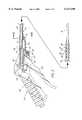
- FIG. 1is a side view of the preferred embodiment of the present invention
- FIG. 2is an exploded view of the preferred embodiment of the present invention
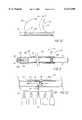
- FIG. 3is a partial cross-sectional view taken in the plane of FIG. 1;
- FIG. 4is a partial cross-sectional view similar to FIG. 3, showing the flow of gas during operation of the preferred embodiment of the present invention
- FIG. 5is a bottom view of a portion of the preferred embodiment of the present invention.
- FIG. 6is a cross-sectional view taken along line 6--6 of FIG. 3;
- FIG. 7is a side view of a portion of the preferred embodiment of the present invention.
- FIGS. 8A and 8Bare side and bottom views, respectively, of another portion of the preferred embodiment of the present invention.
- FIGS. 9A and 9Bare side and end views, respectively, of still another portion of the preferred embodiment of the present invention.
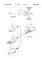
- FIG. 10is a side view of a portion of an alternative embodiment of the present invention.
- FIG. 11is a partially sectioned side view of a second alternative embodiment of the present invention.
- FIG. 12is a partially sectioned side view of a portion of third alternative embodiment of the present invention.
- FIG. 13is a partially sectioned side view of a fourth alternative embodiment of the present invention.
- FIG. 14is a side view of a fifth alternative embodiment of the present invention.
- FIG. 15is a sectioned sided view of a sixth alternative embodiment of the present invention.
- FIG. 16is a schematic view of a seventh alternative embodiment of the present invention.
- FIG. 17is pictorial view of an eighth alternative embodiment of the present invention.
- a pneumatic tissue dissector 10according to the present invention is thereshown and first comprises a supply 12 of a gas suitable for use in an insufflated cavity inside a human or veterinary patient.
- the gas supply 12can be pulsed or continuous, and the gas supplied by the gas supply 12 is preferably the same gas as that employed for establishing and maintaining the insufflated cavity in the patient.
- the gas supply 12is preferably a source of medical grade carbon dioxide gas.
- the dissector 10also comprises a graspable handle 48 adapted to allow the pressurized gas to pass through it, for example, through a passage (not shown) formed in the handle 48.
- a conventional gas filter 14is positioned between the gas supply 12 and the handle 48, and the filter 14, the gas supply 12 and the handle 48 are fluidly connected by a plurality of hoses 20 fixed in position by a plurality of suitable clamps 22.
- the gas filter 14removes any undesired contaminants, oils or the like from the gas supplied by the gas supply 12.
- the pneumatic tissue dissector 10 of the present inventionalso includes a distal end 16 or a dissector tip 16 receivable in an insufflated cavity within a patient.
- the dissector tip 16is for exuding a flow of pressurized gas supplied from the gas supply 12 having sufficient strength to perform the desired cutting or dissecting of tissue within the insufflated cavity.
- a preferred shape for the dissector tip 16is shown in FIGS. 9A and 9B.
- the dissector tip 16preferably defines an exit orifice 18 which is circular in cross-section.
- the dissector tip 16 and its orifice 18can be otherwise shaped as desired to facilitate the cutting or dissecting of particular tissues, but a circular cross-section can be most useful for general dissecting purposes.
- the exit orifice 18can conveniently have a cross-sectional area of about 6.7 mm 2 .
- the size of the orifice 18can be varied, however, to facilitate the performance of specific dissecting procedures.
- the distal end or dissector tipcan include a plurality of interchangeable and detachable tips 104-106 that readily mount (thread) on shaft 110 of the dissector.
- These interchangeable tipsinclude round dissection tip 104 for concentrated flow and tissue cutting, planar dissection tip 106 with an elliptical orifice for blunt dissection, and cutting tip 106 with one or more angled elliptical orifices 109.
- the dissector 10 of the present inventionfurther comprises an inlet arrangement 24 including a gas inlet valve carried by the handle 48 for controlling the flow of pressurized gas from the gas supply 12, to and thereby from the dissector tip 16.
- the gas valve 24is conveniently formed from a valve element 28 received in a recess 36 formed in the handle 48 (FIG. 3).
- a spring 38biases the valve element 28 to a closed position.
- the gas inlet valve 24can be a valve which supplies gas continuously while it is open, or can be a valve which supplies a single pulse of gas when it is opened, depending upon the dissection procedure to be performed.
- the gas supply 12 and the gas valve 24cooperate to provide a flow of pressurized gas exuded from the dissector tip which is compatible with an insufflation cavity pressure of no more than about 25 to 30 mm Hg, preferably, no more than about 15 mm Hg.
- the tissue dissector 10additionally comprises an exhaust system 30 which automatically exhausts and/or releases an amount of gas from the insufflated cavity about equal to that introduced into the insufflated cavity by the dissector tip 16.
- the exhaust system 30comprises an exhaust system inlet 32 positioned adjacent to the dissector tip 16, which is positionable within the insufflated cavity, and an exhaust system outlet 34 spaced from the inlet 32.
- the outlet 34is operable in coordination with operation of the inlet arrangement and, in particular, the gas inlet valve 24.
- “In coordination with”means that either or both of two conditions is met: (a) that the outlet 34 operates at the same time as the inlet arrangement or gas inlet valve 24 operates; or (b) that operation of the outlet 34 exhausts or releases an amount of gas from the insufflated cavity sufficient to prevent an undesirable cycling or increase in intracavital pressure from the dissection performed by the dissector tip 16, without exhausting or releasing so much gas that a threat is presented to maintaining a constant volume for the insufflated cavity.
- the tissue dissector 10 of the present inventionfurther comprises a conduit 26 fluidly connecting the dissector tip 16 to the inlet arrangement or gas inlet valve 24.
- the exhaust system 30further comprises a hollow shaft 40 disposed parallel to and surrounding the conduit 26.
- the exhaust system inlet 32is conveniently formed as at least one transverse perforation 42 through the shaft 40, located near the distal end 74 of the shaft 40.
- a plurality of perforations 42are provided extending around the distal end 74 of the shaft 40.
- the dissector tip 16is rigidly connected to the conduit 26 and to the distal end 74 of the shaft 40 by a connector 88 to which each is connected, for example, by welding.
- the dissector tipcan also be fashioned to be interchangeable such as with tips 104-106 depicted in FIG. 17.
- the handle 48includes a valve body 44 and a joint sleeve 46 for joining the conduit 26 and the hollow shaft 40 to the handle 48.
- the tissue dissector 10further comprises a trigger 58 carried on the handle 48 and operatively connected to the inlet arrangement or gas inlet valve 24 and the exhaust system outlet valve 34.
- the trigger 58is pivotably connected to the handle 48 by a pivot pin 62.
- the exhaust system outlet 34is conveniently carried on the handle 48 and first comprises a seat 50 formed in the handle 48, in particular, in the body 44.
- the shaft 40includes a cut-out or notch 70 (FIG. 7) in registry with the seat 50.
- the relation of the notch 70 and the seat 50is shown in FIG. 5.
- the outlet 34further comprises an exhaust system valve member 52 connected to the trigger 58 by a nut 64 and machine screw 66.
- the valve member 52sealingly engages the seat 50. More particularly, the valve member 52 comprises a generally rigid but partly curved plate 54 (FIGS. 8A and 8B) carrying on it a resilient seal 56 formed, for example, as an elastic band encircling a flat portion of the plate 54.
- the trigger 58moves the seal 56 into and out of engagement with the seat 50 so as to close or open the exhaust system outlet 34.
- the relative positions of the valve member 52 and the seat 50 when the outlet 34 is closedis shown in FIG. 6.
- the trigger 58includes a projection 60 abutting the inlet arrangement or gas inlet valve 24, so that movement of the trigger 58 also actuates the gas inlet valve 24.
- the opening or closing of the exhaust system 30is necessarily coordinated with the actuation of the gas inlet valve 24, and thereby with the exuding of pressurized gas from the dissector tip 16.
- the pneumatic tissue dissector 10 of the present inventionpreferably further comprises a laparoscopic introducer sheath 68 through which the dissector tip 16 and the exhaust system inlet 32 are insertable, so that the dissector tip 16 and the inlet 32 are positionable within an insufflated cavity established in a human or veterinary patient.
- the introducer sheath 68is shown only schematically in FIG. 4 and can be of any conventional or convenient construction.
- the introducer sheath 68must, of course, be shorter than the distance between the exhaust system inlet 32 and the outlet 34, so that the shaft 40 is capable of passing gas from inside the insufflated cavity to outside the insufflated cavity.
- An insufflated cavityis first established in a human or veterinary patient in any conventional manner. Those skilled in this area should be fully familiar with techniques for establishing and maintaining such a cavity, and fully aware of the requisites for protecting patient safety during the practice of such techniques.
- the dissector tip 16 and the exhaust system inlet 32are then positioned in the insufflated cavity.
- a laparoscopic introducer sheath 68is positioned across the insufflated cavity with its distal end 84 located in the cavity and its proximal end 86 lying outside the cavity.
- the positioning of the dissector tip 16 and the inlet 32 in the cavityis then carried out by introducing the tip 16 and inlet 32 through the introducer sheath 68.
- the inlet arrangement or gas inlet valve 24is then actuated (for example, by movement of the trigger 58) so as to exude a flow of pressurized gas from the dissector tip 16 for cutting or dissecting tissue within the cavity, the pressurized gas then passing through the perforations 42 into and through the hollow vent shaft 40, and out the vent outlet valve 34 (opened by the same movement of the trigger 58 that actuated the gas inlet valve 24).
- Arrows 76-82 in FIG. 4indicate the flow of gas into and out of the tissue dissector 10 during its use.
- the exhaust system 30(and, in particular, the outlet 34) could be connected to a source of suction or negative pressure to hasten the venting of gas from the insufflated cavity.
- a source of suction or negative pressureto hasten the venting of gas from the insufflated cavity.
- tissue dissector 10 of the present inventionshould, of course, be composed of medical grade materials which can be sterilized by conventional procedures prior to use.
- the dissector 10can be made of relatively inexpensive synthetic and metallic materials, so that the dissector 10 can be disposed of after a single use, rather than being resterilized and reused. Such reuse, however, is also contemplated within the scope of the invention.
- the hoses 20 connecting the gas supply 12, the filter 14 and the handle 48may be 3/8 inch diameter PVC hose or other suitable hose.
- the filter 14is conveniently a commercially available 0.3 micron filter.
- the handle 48can be composed of an acetal material.
- the total length of the hoses 20 between the gas supply 12 and the handle 48should be sufficient to allow the operating room source of carbon dioxide gas to serve as the gas supply 12, so that the total length of the hoses 20 can conveniently be about 12 feet.
- the total length of the tip 16, conduit 26 and shaft 40 from the tip orifice 18 to the valve body 44is conveniently about 32 cm ⁇ 1 cm.
- the shaft 40, conduit 26 and dissector tip 16can all be composed of stainless steel.
- the tip 16itself can be composed of 6.5 GHW stainless steel tubing about 2.20 in. ⁇ 0.01 in. long, with a taper on its distal 0.020 in. ⁇ 0.002 in. to yield a preferred inner diameter for the orifice 18 of about 0.115 in. (2.92 mm).
- the preferred proportionsare shown in FIGS. 9A and 9B.
- the shaft 40can be composed of stainless steel tubing having an inner diameter of 0.355 in. and an outer diameter of 0.375 in., and a total length of about 12.00 in. ⁇ 0.02 in.
- the perforations 42 through the shaft 40can conveniently have a diameter of 0.150 in.
- the notch 70begins 0.100 in.
- the handle 48is also commercially available as part of a 205 series blow gun from Cejn Industrial Corp., Gurnee, Ill.
- FIGS. 10-17depict a series of alternative embodiments of the present invention.
- a modification of the pneumatic tissue dissector tip 16is shown in FIG. 10 whereby this distal portion is made deflectable to approach a target structure at different angles to facilitate dissection.
- This particular embodimenthas flexible portion 90 just proximal to the distal end 91 of the tip that is, for example, corrugated to permit the tip to be manually deflectable to obtain a desired deflection within the patient. Deflection of the tip can occur once inside the patient or prior to introduction into the body.
- the tipshould be able to be deflected at least 120° to reach normally inaccessible areas. For example, safe and effective dissection around a renal artery or vein would require the ability to deflect the tip in order to dissect behind and around these delicate structures.
- the second embodiment of FIG. 10, which is represented by the phantom lines,includes a tip that is deflectable by means of a remotely-operated control member 92 such as a wire or string running the length of tip which is made flexible by the material used or the structure of the flexible portion.
- a remotely-operated control member 92such as a wire or string running the length of tip which is made flexible by the material used or the structure of the flexible portion. The amount of tension to applied to the control member determines the degree of the angle of tip deflection.
- FIG. 11depicts another alternative embodiment of the present invention that includes an adjustable dissector tip 16 capable of adjusting the amount and/or pattern of the exuded gas or gas flow.
- the distal portion of the pneumatic tissue dissector 10is comprised of an inner member 93 and an adjustable outer sleeve 94. Gas flows through the inner member, exiting via a side port 95 located proximal to distal end 96 of the inner member. The gas then enters an air space 101 between the inner member and an outer member and where it is forced through a short channel 97 and out the tip orifice 18 at the distal end of the outer sheath.
- the outer sheathincludes an internal threaded portion 99 which engages an external threaded portion on the inner member.
- the inner memberto advance or retract relative to the outer member as the outer member is rotated. Advancement of the inner member eventually results in the distal end 96 of the inner member sealing the channel 97 between the air space 101 and the tip orifice 18. The air space is sealed proximally by an O-ring 100. As the advancing distal end 96 of the inner member nears the proximal edge 102 of the channel 97, the stream of gas becomes less focused and is expelled with less velocity. A broad pattern of gas is better suited for blunt dissection, whereas a concentrated flow would be better for more precise cutting of tissue.
- Alternative methods of adjusting the stream of flowinclude having a the gas exit from the distal end of the inner member having a distal orifice of a first diameter.
- the distal orifice of the outer memberhas a second, smaller diameter.
- the distal orifice of the outer memberenlarges to broaden the stream of gas flow. This can be accomplished by the inner member causing a series of leaves surrounding the outer member orifice to spread, increasing the diameter of the outer member orifice.
- FIG. 17depicts yet other alternative embodiments of the present tissue dissector invention in which the size and pattern of the gas stream is varied by the use of different interchangeable and detachable tips 104-106.
- the distal orifice 103 of the proximal shaft 110is connected to any one of a variety of different pneumatic dissector tip 16 configurations. Tips configurations 104, 105, 106 can be threaded onto the external threads 107 of the tip shaft 103.
- a few of the possible tip configurationsinclude a round orifice tip 104 for concentrated flow for cutting through tissue.
- a flattened tip 105is more useful for blunt dissection to separate tissue.
- Another flattened tip design 106includes one or more exit ports 109 along the narrow edge of the paddle-shaped distal portion.
- FIG. 12depicts still yet another alternative embodiment of the present pneumatic dissector invention that includes a means of delivering a selection of one or more medicants, materials, gases, etc. within the patient.
- a series of vials 111 each having a valve 115feed into a common tube 112.
- the outlet 116 of the feeder tube 112enters into the lumen 113 of the dissector tip 16 and occurs at a point 116 just distal to a venturi 114 within the lumen. Gas flowing through the venturi creates a venturi effect whereby the lowered pressure distal to the venturi allows the medicants, material, gases, etc. to be drawn from the vial, introduced into the stream of gas 117, and sprayed from the dissector tip orifice.
- medicants and the likeare introduced into a patient.
- the effectis very similar to that of paint being sprayed from a spray gun.
- a material for this applicationwould be fibrin glue to seal an anastomosis (e.g., pyeloplasty, vascular), seal a cut surface of a parenchymal structure (e.g., kidney, liver, spleen), or to stop an area of diffuse bleeding, such as that following dissection.
- Other uses for the devicewould include spraying growth factors to stimulate healing or anastomosis, heparin solution in patients with malignancies to preclude seeding of malignant cells, and small intestinal submucosa (SIS) at the port sites to preclude help prevent scar formation.
- SISsmall intestinal submucosa
- FIG. 13depicts a alternative embodiment of the pneumatic tissue dissector 10 in which the tip of the device includes an electrosurgical probe or element 118 that assumes the shape of a right angle hook 123 as it is advanced out of a lumen 119 in the wall 120 of the dissector's hollow tip 16.
- the configuration of the hookis such that as tissue is bluntly dissected, any uncovered small vessels are immediately electrocoagulated and divided. This provides the capability for rapid and bloodless dissection.
- FIG. 14depicts another method for adding electrosurgical capabilities in which the distal tip 91 itself is electrified so that it can also function as an electrosurgical probe when current is supplied under the control of the operator.
- a further modification of the pneumatic tissue dissectoris shown in FIG. 14, whereby the distal tip 91 has a roughened surface 123 to aid with blunt mechanical dissection.
- FIG. 15depicts another alternative embodiment of the present invention that includes a central passageway 121 that can accommodate an optical fiber 122, such as for transmitting Holmium laser light for cutting and/or coagulation.
- the passageway diametermust be at least 500 microns to accommodate a typical laser fiber.
- FIG. 16depicts a schematic view of an alternative embodiment that includes a triple stopcock or three way valve that permits switching the incoming/outgoing line between the CO 2 source for pneumatic dissector; a pump for aspirating blood or smoke resulting from electrocautery; and an irrigation system for introducing saline or other solutions to clear blood from the field, or to introduce medicants such as an antibiotic solution.
- a combinational pneumatic tissue dissector with these additional capabilitieseliminates the need and expense of a separate irrigator/aspirator system.
- the pneumatic dissector 10 of the present inventionis particularly advantageous over prior devices in a variety of ways.
- the coordinated operation of the gas inlet valve and the exhaust systemreliably, affirmatively and automatically prevents the undesired build-up of pressure in the insufflation cavity while the dissector is in use, while simultaneously preventing the collapse of the cavity from over-exhausting.
- Intracavity pressure and cavity volumedo not cycle up and down as might be the case if the cavity pressure was reduced by a pop off valve, and the surgeon need not fear a failure of the exhaust system outlet of the present invention to open, in contrast to the use of a pop off valve.
- the present inventionis expected to result in significant cost savings, because it reduces the time needed to perform surgical procedures and is relatively low in cost to manufacture. Further, because it operates at pressures several times higher than the pressures used in hydrodissectors, the risk of misidentification of tissue planes during its use is substantially reduced.
- the present inventionalso avoids the pooling of liquids in the insufflated cavity associated with the use of hydrodissectors and the like, and does not require the suction needed to remove the smoke produced by electrosurgical cutters or lasers.
- the present inventionis useful in the performance of surgical procedures, and therefore finds applicability in human and veterinary medicine.
Landscapes
- Health & Medical Sciences (AREA)
- Life Sciences & Earth Sciences (AREA)
- Surgery (AREA)
- Heart & Thoracic Surgery (AREA)
- Engineering & Computer Science (AREA)
- Biomedical Technology (AREA)
- Animal Behavior & Ethology (AREA)
- General Health & Medical Sciences (AREA)
- Public Health (AREA)
- Veterinary Medicine (AREA)
- Nuclear Medicine, Radiotherapy & Molecular Imaging (AREA)
- Medical Informatics (AREA)
- Molecular Biology (AREA)
- Pathology (AREA)
- Oral & Maxillofacial Surgery (AREA)
- Anesthesiology (AREA)
- Hematology (AREA)
- Plasma & Fusion (AREA)
- Vascular Medicine (AREA)
- Physics & Mathematics (AREA)
- Pulmonology (AREA)
- Otolaryngology (AREA)
- Surgical Instruments (AREA)
- Laser Surgery Devices (AREA)
- External Artificial Organs (AREA)
- Sampling And Sample Adjustment (AREA)
- Apparatus For Radiation Diagnosis (AREA)
- Endoscopes (AREA)
Abstract
Description
Claims (24)
Priority Applications (1)
| Application Number | Priority Date | Filing Date | Title |
|---|---|---|---|
| US09/115,008US6117150A (en) | 1997-07-14 | 1998-07-14 | Pneumatic tissue dissector with exhaust system |
Applications Claiming Priority (2)
| Application Number | Priority Date | Filing Date | Title |
|---|---|---|---|
| US5242097P | 1997-07-14 | 1997-07-14 | |
| US09/115,008US6117150A (en) | 1997-07-14 | 1998-07-14 | Pneumatic tissue dissector with exhaust system |
Publications (1)
| Publication Number | Publication Date |
|---|---|
| US6117150Atrue US6117150A (en) | 2000-09-12 |
Family
ID=21977509
Family Applications (1)
| Application Number | Title | Priority Date | Filing Date |
|---|---|---|---|
| US09/115,008Expired - Fee RelatedUS6117150A (en) | 1997-07-14 | 1998-07-14 | Pneumatic tissue dissector with exhaust system |
Country Status (9)
| Country | Link |
|---|---|
| US (1) | US6117150A (en) |
| EP (1) | EP0996368B1 (en) |
| JP (1) | JP2001509411A (en) |
| KR (1) | KR20010021717A (en) |
| AT (1) | ATE269668T1 (en) |
| AU (1) | AU745353B2 (en) |
| CA (1) | CA2296305C (en) |
| DE (1) | DE69824728T2 (en) |
| WO (1) | WO1999002089A1 (en) |
Cited By (40)
| Publication number | Priority date | Publication date | Assignee | Title |
|---|---|---|---|---|
| USD436165S1 (en) | 2000-02-11 | 2001-01-09 | Bristol-Myers Squibb Company | Medical suction/lavage handpiece |
| US6368299B1 (en)* | 1998-10-09 | 2002-04-09 | William W. Cimino | Ultrasonic probe and method for improved fragmentation |
| US20030144656A1 (en)* | 2002-01-25 | 2003-07-31 | Medtronic, Inc | Fluid-assisted electrosurgical instrument with shapeable electrode |
| US20030181917A1 (en)* | 2002-01-24 | 2003-09-25 | The Regents Of The University Of California | Aerosol device to deliver bioactive agent |
| US6676627B1 (en)* | 1990-08-06 | 2004-01-13 | Possis Medical, Inc. | Crossflow thrombectomy catheter and system |
| US20050203561A1 (en)* | 2004-03-09 | 2005-09-15 | Palmer Joetta R. | Lighted dissector and method for use |
| US7029450B2 (en) | 2001-12-14 | 2006-04-18 | Boston Scientific Scimed, Inc. | Dilation catheter assembly and related methods |
| US20070225659A1 (en)* | 2006-03-21 | 2007-09-27 | Cook Incorporated | Introducer sheath having frangible tip |
| US20080188831A1 (en)* | 2007-02-06 | 2008-08-07 | Possis Medical, Inc. | Miniature flexible thrombectomy catheter |
| US20080300547A1 (en)* | 2007-06-01 | 2008-12-04 | Bakos Gregory J | Integrated securement and closure apparatus |
| US20080300532A1 (en)* | 2004-12-10 | 2008-12-04 | Possis Medical, Inc. | Enhanced cross stream mechanical thrombectomy catheter |
| US20090043158A1 (en)* | 2007-08-10 | 2009-02-12 | Wei-Chen Hon | Conduit introducer, conduit assembly and conduit-implanting device |
| US7572244B2 (en) | 2004-08-02 | 2009-08-11 | Medrad, Inc. | Miniature cross stream thrombectomy catheter |
| US20090326547A1 (en)* | 2006-03-16 | 2009-12-31 | Bulent Celik | Compressed air dissector (air jet scraper) |
| US20100249799A1 (en)* | 2009-03-27 | 2010-09-30 | Hazem Barmada | System and method for removing an implanted catheter from a patient |
| US7996974B2 (en) | 2007-02-06 | 2011-08-16 | Medrad, Inc. | Method of manufacturing a miniature flexible thrombectomy catheter |
| US8118777B2 (en) | 2009-05-29 | 2012-02-21 | Cook Medical Technologies Llc | Systems and methods for delivering therapeutic agents |
| CN102481157A (en)* | 2009-04-08 | 2012-05-30 | 厄比电子医学有限责任公司 | Water jet surgical instrument |
| CN102648866A (en)* | 2011-02-28 | 2012-08-29 | 精工爱普生株式会社 | Surgical instrument |
| US8361054B2 (en) | 2008-12-23 | 2013-01-29 | Cook Medical Technologies Llc | Apparatus and methods for containing and delivering therapeutic agents |
| US20130060335A1 (en)* | 2011-04-27 | 2013-03-07 | Reinhard Bornemann | Device for cell spraying, manufacturing of the device, method for spraying with the device and a cell suspension sprayed with the device |
| CN103084111A (en)* | 2011-11-03 | 2013-05-08 | 赫罗伊斯医疗有限责任公司 | Apparatus and method for the generation of vacuum for vacuum cementing systems |
| US8518035B2 (en) | 2008-12-22 | 2013-08-27 | Cook Medical Technologies Llc | Electrosurgical rotating cutting device |
| US9101744B2 (en) | 2009-05-29 | 2015-08-11 | Cook Medical Technologies Llc | Systems and methods for delivering therapeutic agents |
| US9131959B2 (en) | 2011-08-22 | 2015-09-15 | Cook Medical Technologies Llc | Splittable dilator delivery system |
| US20170042731A1 (en)* | 2014-04-23 | 2017-02-16 | Makoto Kishimoto | Intraocular surgery system |
| US9610430B2 (en) | 2006-09-11 | 2017-04-04 | Renovacare Sciences Corp. | Cell spraying device, method and sprayed cell suspension |
| CN107049474A (en)* | 2017-03-30 | 2017-08-18 | 吴彬 | One kind electric knife of tissue separation and its method of work |
| US9839772B2 (en) | 2008-05-06 | 2017-12-12 | Cook Medical Technologies Llc | Apparatus and methods for delivering therapeutic agents |
| US9867931B2 (en) | 2013-10-02 | 2018-01-16 | Cook Medical Technologies Llc | Therapeutic agents for delivery using a catheter and pressure source |
| USD831819S1 (en) | 2016-01-22 | 2018-10-23 | Medline Industries, Inc. | Irrigator |
| CN110664479A (en)* | 2019-09-30 | 2020-01-10 | 严立 | Gas flow rate adjusting device for controlling gas supply device and jet stripping system |
| CN110711024A (en)* | 2019-09-30 | 2020-01-21 | 严立 | Foot-controlled gas flow rate device and air jet stripping system to control the air supply device |
| US10582914B2 (en)* | 2016-01-15 | 2020-03-10 | Covidien Lp | Navigable endobronchial tool to access tissue outside a bronchus |
| US11040363B2 (en) | 2016-06-14 | 2021-06-22 | Renovacare Sciences Corp. | Modular device for cell spraying |
| US11441700B2 (en)* | 2019-04-24 | 2022-09-13 | Alcon Inc. | Valve cooling and noise suppression |
| CN116269643A (en)* | 2023-03-16 | 2023-06-23 | 杭州好克光电仪器有限公司 | Perfusion suction device capable of measuring intra-cavity pressure and using method |
| US11931227B2 (en) | 2013-03-15 | 2024-03-19 | Cook Medical Technologies Llc | Bimodal treatment methods and compositions for gastrointestinal lesions with active bleeding |
| CN119157606A (en)* | 2024-11-17 | 2024-12-20 | 上海市东方医院(同济大学附属东方医院) | Laparoscopic grasping forceps with controllable channels and use method thereof |
| US12226568B2 (en) | 2020-06-05 | 2025-02-18 | Cook Medical Technologies Llc | Medical scopes for delivering therapeutic agents |
Families Citing this family (20)
| Publication number | Priority date | Publication date | Assignee | Title |
|---|---|---|---|---|
| JP4287273B2 (en)* | 2001-09-24 | 2009-07-01 | アプライド メディカル リソーシーズ コーポレイション | Bladeless obturator |
| WO2003096879A2 (en) | 2002-05-16 | 2003-11-27 | Applied Medical Resources Corporation | Cone tip obturator |
| EP2545862B1 (en) | 2003-10-03 | 2015-09-30 | Applied Medical Resources Corporation | Bladeless optical obturator with a lock for an optical instrument |
| EP2545870B1 (en) | 2004-06-29 | 2015-11-04 | Applied Medical Resources Corporation | Insufflating optical surgical instrument |
| AU2007303069B2 (en) | 2006-10-06 | 2013-03-21 | Applied Medical Resources Corporation | Visual insufflation port |
| US20090076505A1 (en)* | 2007-09-13 | 2009-03-19 | Arts Gene H | Electrosurgical instrument |
| EP2851020B1 (en) | 2008-01-25 | 2016-01-20 | Applied Medical Resources Corporation | Insufflating access system |
| WO2009147639A2 (en)* | 2008-06-06 | 2009-12-10 | Romeo Bardini | Tissue dissection device and method |
| EP2328487B1 (en) | 2008-09-29 | 2018-04-18 | Applied Medical Resources Corporation | First-entry trocar system |
| JP4778545B2 (en)* | 2008-10-20 | 2011-09-21 | セイコーエプソン株式会社 | Fluid ejection device |
| CN101695788B (en)* | 2009-10-30 | 2011-08-10 | 天津振汉机械装备有限公司 | Process for assembling and spot welding of circular seams of tank body of container |
| KR20140018324A (en) | 2011-05-02 | 2014-02-12 | 어플라이드 메디컬 리소시스 코포레이션 | Low-profile surgical universal access port |
| DE102012009078A1 (en)* | 2012-05-09 | 2013-11-14 | Karl Storz Gmbh & Co. Kg | Insufflation device and method |
| WO2016012936A1 (en) | 2014-07-21 | 2016-01-28 | Ab Medica Holding S.P.A. | Dissector device |
| CN104622562B (en)* | 2015-03-06 | 2017-01-04 | 常州市康心医疗器械有限公司 | Pipe endoscope of a kind of Wicresoft esophagus extricator |
| KR101821893B1 (en)* | 2016-10-06 | 2018-01-25 | 인제대학교 산학협력단 | Removable surgical smoke suction unit for laparoscopic surgery instrument |
| JP2019097962A (en)* | 2017-12-05 | 2019-06-24 | 京セラ株式会社 | Laparoscopic surgical instrument |
| KR102095029B1 (en)* | 2018-03-30 | 2020-03-31 | 한림대학교 산학협력단 | Harmonic scalpel assembly having gas syringe module |
| RU2711257C1 (en)* | 2019-05-15 | 2020-01-15 | Федеральное государственное бюджетное образовательное учреждение высшего образования "Казанский Государственный медицинский университет" Министерства здравоохранения Российской Федерации | Method of lymphangioma treatment |
| FR3104019B1 (en)* | 2019-12-05 | 2023-10-06 | Ab Medica | Instrument for blowing a gas into a living organ to facilitate medical dissection of this organ. |
Citations (6)
| Publication number | Priority date | Publication date | Assignee | Title |
|---|---|---|---|---|
| US4913698A (en)* | 1987-10-26 | 1990-04-03 | Marui Ika Company, Limited | Aqua-stream and aspirator for brain surgery |
| US4950238A (en)* | 1988-07-07 | 1990-08-21 | Clarence E. Sikes | Hydro-rotary vascular catheter |
| US4957492A (en)* | 1988-12-07 | 1990-09-18 | Cabot Medical Corporation | Apparatus for collecting and handling tissue during uterine evacuation procedure |
| US5022414A (en)* | 1979-12-13 | 1991-06-11 | Joseph J. Berke | Tissue separator method |
| US5135482A (en)* | 1985-12-31 | 1992-08-04 | Arnold Neracher | Hydrodynamic device for the elimination of an organic deposit obstructing a vessel of a human body |
| US5573504A (en)* | 1990-01-26 | 1996-11-12 | C. R. Bard, Inc. | Composite irrigation and suction probe and valve |
Family Cites Families (3)
| Publication number | Priority date | Publication date | Assignee | Title |
|---|---|---|---|---|
| US4118830A (en) | 1977-04-13 | 1978-10-10 | Weiland Richard J | Device for skinning animals and fowl |
| US4709697A (en) | 1980-12-09 | 1987-12-01 | Joseph J. Berke | Tissue pneumatic separator structure and method |
| US4357940A (en) | 1979-12-13 | 1982-11-09 | Detroit Neurosurgical Foundation | Tissue pneumatic separator structure |
- 1998
- 1998-07-14DEDE69824728Tpatent/DE69824728T2/ennot_activeExpired - Fee Related
- 1998-07-14KRKR1020007000276Apatent/KR20010021717A/ennot_activeWithdrawn
- 1998-07-14JPJP2000501693Apatent/JP2001509411A/enactivePending
- 1998-07-14WOPCT/US1998/014535patent/WO1999002089A1/enactiveIP Right Grant
- 1998-07-14AUAU84020/98Apatent/AU745353B2/ennot_activeCeased
- 1998-07-14CACA002296305Apatent/CA2296305C/ennot_activeExpired - Fee Related
- 1998-07-14EPEP98934517Apatent/EP0996368B1/ennot_activeExpired - Lifetime
- 1998-07-14ATAT98934517Tpatent/ATE269668T1/ennot_activeIP Right Cessation
- 1998-07-14USUS09/115,008patent/US6117150A/ennot_activeExpired - Fee Related
Patent Citations (6)
| Publication number | Priority date | Publication date | Assignee | Title |
|---|---|---|---|---|
| US5022414A (en)* | 1979-12-13 | 1991-06-11 | Joseph J. Berke | Tissue separator method |
| US5135482A (en)* | 1985-12-31 | 1992-08-04 | Arnold Neracher | Hydrodynamic device for the elimination of an organic deposit obstructing a vessel of a human body |
| US4913698A (en)* | 1987-10-26 | 1990-04-03 | Marui Ika Company, Limited | Aqua-stream and aspirator for brain surgery |
| US4950238A (en)* | 1988-07-07 | 1990-08-21 | Clarence E. Sikes | Hydro-rotary vascular catheter |
| US4957492A (en)* | 1988-12-07 | 1990-09-18 | Cabot Medical Corporation | Apparatus for collecting and handling tissue during uterine evacuation procedure |
| US5573504A (en)* | 1990-01-26 | 1996-11-12 | C. R. Bard, Inc. | Composite irrigation and suction probe and valve |
Cited By (74)
| Publication number | Priority date | Publication date | Assignee | Title |
|---|---|---|---|---|
| US6676627B1 (en)* | 1990-08-06 | 2004-01-13 | Possis Medical, Inc. | Crossflow thrombectomy catheter and system |
| US6368299B1 (en)* | 1998-10-09 | 2002-04-09 | William W. Cimino | Ultrasonic probe and method for improved fragmentation |
| USD436165S1 (en) | 2000-02-11 | 2001-01-09 | Bristol-Myers Squibb Company | Medical suction/lavage handpiece |
| US7029450B2 (en) | 2001-12-14 | 2006-04-18 | Boston Scientific Scimed, Inc. | Dilation catheter assembly and related methods |
| US7544177B2 (en) | 2002-01-24 | 2009-06-09 | The Regents Of The University Of California | Aerosol device to deliver bioactive agent |
| US20030181917A1 (en)* | 2002-01-24 | 2003-09-25 | The Regents Of The University Of California | Aerosol device to deliver bioactive agent |
| US20030144656A1 (en)* | 2002-01-25 | 2003-07-31 | Medtronic, Inc | Fluid-assisted electrosurgical instrument with shapeable electrode |
| US7967816B2 (en) | 2002-01-25 | 2011-06-28 | Medtronic, Inc. | Fluid-assisted electrosurgical instrument with shapeable electrode |
| US8998843B2 (en) | 2003-06-05 | 2015-04-07 | Boston Scientific Limited | Enhanced cross stream mechanical thrombectomy catheter |
| US9833257B2 (en) | 2003-06-05 | 2017-12-05 | Boston Scientific Limited | Enhanced cross stream mechanical thrombectomy catheter |
| US20050203561A1 (en)* | 2004-03-09 | 2005-09-15 | Palmer Joetta R. | Lighted dissector and method for use |
| US7572244B2 (en) | 2004-08-02 | 2009-08-11 | Medrad, Inc. | Miniature cross stream thrombectomy catheter |
| US10314609B2 (en) | 2004-12-10 | 2019-06-11 | Boston Scientific Limited | Enhanced cross stream mechanical thrombectomy catheter |
| US8597238B2 (en) | 2004-12-10 | 2013-12-03 | Medrad, Inc. | Enhanced cross stream mechanical thrombectomy catheter |
| US20080300532A1 (en)* | 2004-12-10 | 2008-12-04 | Possis Medical, Inc. | Enhanced cross stream mechanical thrombectomy catheter |
| US8162877B2 (en) | 2004-12-10 | 2012-04-24 | Medrad, Inc. | Enhanced cross stream mechanical thrombectomy catheter |
| US20090326547A1 (en)* | 2006-03-16 | 2009-12-31 | Bulent Celik | Compressed air dissector (air jet scraper) |
| US8641725B2 (en)* | 2006-03-16 | 2014-02-04 | Tubitak | Compressed air dissector (air jet scraper) |
| US20070225659A1 (en)* | 2006-03-21 | 2007-09-27 | Cook Incorporated | Introducer sheath having frangible tip |
| US9610430B2 (en) | 2006-09-11 | 2017-04-04 | Renovacare Sciences Corp. | Cell spraying device, method and sprayed cell suspension |
| US7996974B2 (en) | 2007-02-06 | 2011-08-16 | Medrad, Inc. | Method of manufacturing a miniature flexible thrombectomy catheter |
| US8012117B2 (en) | 2007-02-06 | 2011-09-06 | Medrad, Inc. | Miniature flexible thrombectomy catheter |
| US20080188831A1 (en)* | 2007-02-06 | 2008-08-07 | Possis Medical, Inc. | Miniature flexible thrombectomy catheter |
| US7967842B2 (en)* | 2007-06-01 | 2011-06-28 | Ethicon Endo-Surgery, Inc. | Integrated securement and closure apparatus |
| US20080300547A1 (en)* | 2007-06-01 | 2008-12-04 | Bakos Gregory J | Integrated securement and closure apparatus |
| US20090043158A1 (en)* | 2007-08-10 | 2009-02-12 | Wei-Chen Hon | Conduit introducer, conduit assembly and conduit-implanting device |
| US10994110B2 (en) | 2008-05-06 | 2021-05-04 | Cook Medical Technologies Llc | Apparatus and methods for delivering therapeutic agents |
| US9839772B2 (en) | 2008-05-06 | 2017-12-12 | Cook Medical Technologies Llc | Apparatus and methods for delivering therapeutic agents |
| US8518035B2 (en) | 2008-12-22 | 2013-08-27 | Cook Medical Technologies Llc | Electrosurgical rotating cutting device |
| US8361054B2 (en) | 2008-12-23 | 2013-01-29 | Cook Medical Technologies Llc | Apparatus and methods for containing and delivering therapeutic agents |
| US20100249799A1 (en)* | 2009-03-27 | 2010-09-30 | Hazem Barmada | System and method for removing an implanted catheter from a patient |
| US8109939B2 (en)* | 2009-03-27 | 2012-02-07 | Hazem Barmada | System and method for removing an implanted catheter from a patient |
| CN102481157B (en)* | 2009-04-08 | 2015-10-07 | 厄比电子医学有限责任公司 | Water jet surgical instrument |
| US9381034B2 (en) | 2009-04-08 | 2016-07-05 | Erbe Elektromedizin Gmbh | Water jet surgical instrument |
| CN102481157A (en)* | 2009-04-08 | 2012-05-30 | 厄比电子医学有限责任公司 | Water jet surgical instrument |
| US8728032B2 (en) | 2009-05-29 | 2014-05-20 | Cook Medical Technologies Llc | Systems and methods for delivering therapeutic agents |
| US9101744B2 (en) | 2009-05-29 | 2015-08-11 | Cook Medical Technologies Llc | Systems and methods for delivering therapeutic agents |
| US8118777B2 (en) | 2009-05-29 | 2012-02-21 | Cook Medical Technologies Llc | Systems and methods for delivering therapeutic agents |
| US9375533B2 (en) | 2009-05-29 | 2016-06-28 | Cook Medical Technologies Llc | Systems and methods for delivering therapeutic agents |
| CN102648866A (en)* | 2011-02-28 | 2012-08-29 | 精工爱普生株式会社 | Surgical instrument |
| EP2491875A3 (en)* | 2011-02-28 | 2014-06-25 | Seiko Epson Corporation | Fluid ejection device |
| CN102648866B (en)* | 2011-02-28 | 2016-07-20 | 精工爱普生株式会社 | Operation device |
| US20120221027A1 (en)* | 2011-02-28 | 2012-08-30 | Seiko Epson Corporation | Surgical instrument |
| US10376658B2 (en) | 2011-04-27 | 2019-08-13 | Renovacare Sciences Corp. | Device for cell spraying |
| US9505000B2 (en)* | 2011-04-27 | 2016-11-29 | Renovacare Sciences Corp. | Device for cell spraying, manufacturing of the device, method for spraying with the device and a cell suspension sprayed with the device |
| US11135380B2 (en) | 2011-04-27 | 2021-10-05 | Renovacare Sciences Corp. | Device for cell spraying |
| US20130060335A1 (en)* | 2011-04-27 | 2013-03-07 | Reinhard Bornemann | Device for cell spraying, manufacturing of the device, method for spraying with the device and a cell suspension sprayed with the device |
| US9131959B2 (en) | 2011-08-22 | 2015-09-15 | Cook Medical Technologies Llc | Splittable dilator delivery system |
| US9470245B2 (en) | 2011-11-03 | 2016-10-18 | Heraeus Medical Gmbh | Device and method for generating vacuum for vacuum cementing systems |
| CN103084111A (en)* | 2011-11-03 | 2013-05-08 | 赫罗伊斯医疗有限责任公司 | Apparatus and method for the generation of vacuum for vacuum cementing systems |
| CN103084111B (en)* | 2011-11-03 | 2015-09-02 | 赫罗伊斯医疗有限责任公司 | For the vacuum equipment of vacuum impregnating cement system and method |
| US12102510B2 (en) | 2013-03-15 | 2024-10-01 | Wilmington Trust, National Association, As Collateral Agent | Bimodal treatment methods and compositions for gastrointestinal lesions with active bleeding |
| US11931227B2 (en) | 2013-03-15 | 2024-03-19 | Cook Medical Technologies Llc | Bimodal treatment methods and compositions for gastrointestinal lesions with active bleeding |
| US11696984B2 (en) | 2013-10-02 | 2023-07-11 | Cook Medical Technologies Llc | Therapeutic agents for delivery using a catheter and pressure source |
| US10806853B2 (en) | 2013-10-02 | 2020-10-20 | Cook Medical Technologies Llc | Therapeutic agents for delivery using a catheter and pressure source |
| US12318573B2 (en) | 2013-10-02 | 2025-06-03 | Cook Medical Technologies Llc | Therapeutic agents for delivery using a catheter and pressure source |
| US9867931B2 (en) | 2013-10-02 | 2018-01-16 | Cook Medical Technologies Llc | Therapeutic agents for delivery using a catheter and pressure source |
| US10231869B2 (en)* | 2014-04-23 | 2019-03-19 | Senju Pharmaceutical Co., Ltd. | Intraocular surgery system |
| US20170042731A1 (en)* | 2014-04-23 | 2017-02-16 | Makoto Kishimoto | Intraocular surgery system |
| US11559290B2 (en) | 2016-01-15 | 2023-01-24 | Covidien Lp | Navigable endobronchial tool to access tissue outside a bronchus |
| US10582914B2 (en)* | 2016-01-15 | 2020-03-10 | Covidien Lp | Navigable endobronchial tool to access tissue outside a bronchus |
| USD896364S1 (en) | 2016-01-22 | 2020-09-15 | Medline Industries, Inc. | Irrigator |
| USD874643S1 (en) | 2016-01-22 | 2020-02-04 | Medline Industries, Inc. | Irrigator |
| USD831819S1 (en) | 2016-01-22 | 2018-10-23 | Medline Industries, Inc. | Irrigator |
| US11040363B2 (en) | 2016-06-14 | 2021-06-22 | Renovacare Sciences Corp. | Modular device for cell spraying |
| CN107049474A (en)* | 2017-03-30 | 2017-08-18 | 吴彬 | One kind electric knife of tissue separation and its method of work |
| US11441700B2 (en)* | 2019-04-24 | 2022-09-13 | Alcon Inc. | Valve cooling and noise suppression |
| CN110711024B (en)* | 2019-09-30 | 2024-05-17 | 首都医科大学附属北京同仁医院 | Foot-controlled gas flow rate device for controlling gas supply device and jet stripping system |
| CN110664479A (en)* | 2019-09-30 | 2020-01-10 | 严立 | Gas flow rate adjusting device for controlling gas supply device and jet stripping system |
| CN110711024A (en)* | 2019-09-30 | 2020-01-21 | 严立 | Foot-controlled gas flow rate device and air jet stripping system to control the air supply device |
| US12226568B2 (en) | 2020-06-05 | 2025-02-18 | Cook Medical Technologies Llc | Medical scopes for delivering therapeutic agents |
| CN116269643B (en)* | 2023-03-16 | 2023-10-03 | 杭州好克光电仪器有限公司 | Perfusion suction device capable of measuring intra-cavity pressure |
| CN116269643A (en)* | 2023-03-16 | 2023-06-23 | 杭州好克光电仪器有限公司 | Perfusion suction device capable of measuring intra-cavity pressure and using method |
| CN119157606A (en)* | 2024-11-17 | 2024-12-20 | 上海市东方医院(同济大学附属东方医院) | Laparoscopic grasping forceps with controllable channels and use method thereof |
Also Published As
| Publication number | Publication date |
|---|---|
| CA2296305A1 (en) | 1999-01-21 |
| ATE269668T1 (en) | 2004-07-15 |
| WO1999002089A1 (en) | 1999-01-21 |
| EP0996368A1 (en) | 2000-05-03 |
| AU8402098A (en) | 1999-02-08 |
| EP0996368B1 (en) | 2004-06-23 |
| DE69824728T2 (en) | 2005-08-04 |
| AU745353B2 (en) | 2002-03-21 |
| CA2296305C (en) | 2006-09-12 |
| DE69824728D1 (en) | 2004-07-29 |
| KR20010021717A (en) | 2001-03-15 |
| JP2001509411A (en) | 2001-07-24 |
Similar Documents
| Publication | Publication Date | Title |
|---|---|---|
| US6117150A (en) | Pneumatic tissue dissector with exhaust system | |
| US5368560A (en) | Suction nozzle | |
| JP3423733B2 (en) | Endoscopic surgical instruments for suction and irrigation | |
| US6375635B1 (en) | Fluid jet surgical instruments | |
| US5902264A (en) | Endoscopic surgical instrument for aspiration and irrigation | |
| US5527330A (en) | Fluid cutting instrument | |
| US5779662A (en) | Laparoscopic tissue resection system | |
| US20140336634A1 (en) | Multifunctional attachment for electrocautery surgical device | |
| EP0578376A1 (en) | Ultrasonic surgical aspirator | |
| US5310406A (en) | Endoscopic aspirator surgical instrument | |
| US20240180582A1 (en) | Hydro dissection and suction laparoscopic instruments and methods of use | |
| JP3349716B2 (en) | Water jet surgical device | |
| JP3205565B2 (en) | Endoscope device with jet nozzle for jet jet surgery | |
| US20240181179A1 (en) | System and method for visualization of a surgical site during a medical procedure | |
| JP2025508261A (en) | Laparoscopic devices for hydrodissection and aspiration and methods of use | |
| WO2025080737A1 (en) | Hydro dissection, irrigation, and suction electrocautery devices and methods of use | |
| CA2497598C (en) | Endoscopic surgical instrument for aspiration and irrigation | |
| JP2016193139A (en) | Fluid switching device and insertion system |
Legal Events
| Date | Code | Title | Description |
|---|---|---|---|
| AS | Assignment | Owner name:COOK UROLOGICAL INC., INDIANA Free format text:ASSIGNMENT OF ASSIGNORS INTEREST;ASSIGNORS:PINGLETON, EDWARD D.;BUTLER, GARY L.;HOLLINGER, DONALD R.;AND OTHERS;REEL/FRAME:010586/0145 Effective date:19981119 Owner name:MED INSTITUTE, INC., INDIANA Free format text:ASSIGNMENT OF ASSIGNORS INTEREST;ASSIGNORS:PINGLETON, EDWARD D.;BUTLER, GARY L.;HOLLINGER, DONALD R.;AND OTHERS;REEL/FRAME:010586/0145 Effective date:19981119 | |
| AS | Assignment | Owner name:PROLEPSIS, L.L.C., MISSOURI Free format text:ASSIGNMENT OF ASSIGNORS INTEREST;ASSIGNOR:MEDICAL ENGINEERING AND DEVELOPMENT INSTITUTE, INC. D/B/A MED INSTITUTE, INC.;REEL/FRAME:012418/0846 Effective date:20010928 Owner name:VANCE PRODUCTS INC. D/B/A COOK UROLOGICAL INC., IN Free format text:ASSIGNMENT OF ASSIGNORS INTEREST;ASSIGNORS:PINGLETON, EDWARD D.;BUTLER, GARY L.;HOLLINGER, DONALD R.;AND OTHERS;REEL/FRAME:012418/0849 Effective date:20011001 Owner name:PROLEPSIS, L.L.C,, MISSOURI Free format text:ASSIGNMENT OF ASSIGNORS INTEREST;ASSIGNOR:VANCE PRODUCTS INC. D/B/A COOK UROLOGICAL INC.;REEL/FRAME:012418/0862 Effective date:20010928 Owner name:MEDICAL ENGINEERING AND DEVELOPMENT INSTITUTE, INC Free format text:ASSIGNMENT OF ASSIGNORS INTEREST;ASSIGNORS:PINGLETON, EDWARD D.;BUTLER, GARY L.;HOLLINGER, DONALD R.;AND OTHERS;REEL/FRAME:012418/0849 Effective date:20011001 | |
| AS | Assignment | Owner name:APPLIED MEDICAL RESOURCES CORPORATION, CALIFORNIA Free format text:ASSIGNMENT OF ASSIGNORS INTEREST;ASSIGNORS:CLAYMAN, CAROL;CLAYMAN, RALPH V.;REEL/FRAME:013288/0019;SIGNING DATES FROM 20020613 TO 20020617 | |
| FPAY | Fee payment | Year of fee payment:4 | |
| SULP | Surcharge for late payment | ||
| AS | Assignment | Owner name:CLAYMAN, RALPH V., M.D., CALIFORNIA Free format text:ASSIGNMENT OF ASSIGNORS INTEREST;ASSIGNOR:APPLIED MEDICAL RESOURCES CORPORATION;REEL/FRAME:020426/0113 Effective date:20071017 | |
| AS | Assignment | Owner name:APPLIED MEDICAL RESOURCES CORPORATION, CALIFORNIA Free format text:ASSIGNMENT OF ASSIGNORS INTEREST;ASSIGNOR:PROLEPSIS, LLC;REEL/FRAME:020468/0483 Effective date:20020226 | |
| FPAY | Fee payment | Year of fee payment:8 | |
| REMI | Maintenance fee reminder mailed | ||
| LAPS | Lapse for failure to pay maintenance fees | ||
| STCH | Information on status: patent discontinuation | Free format text:PATENT EXPIRED DUE TO NONPAYMENT OF MAINTENANCE FEES UNDER 37 CFR 1.362 | |
| FP | Lapsed due to failure to pay maintenance fee | Effective date:20120912 |