US6117076A - Patient monitoring system and method - Google Patents
Patient monitoring system and methodDownload PDFInfo
- Publication number
- US6117076A US6117076AUS09/157,762US15776298AUS6117076AUS 6117076 AUS6117076 AUS 6117076AUS 15776298 AUS15776298 AUS 15776298AUS 6117076 AUS6117076 AUS 6117076A
- Authority
- US
- United States
- Prior art keywords
- signals
- monitoring device
- patient
- controller
- processor
- Prior art date
- Legal status (The legal status is an assumption and is not a legal conclusion. Google has not performed a legal analysis and makes no representation as to the accuracy of the status listed.)
- Expired - Lifetime
Links
Images

Classifications
- A—HUMAN NECESSITIES
- A61—MEDICAL OR VETERINARY SCIENCE; HYGIENE
- A61B—DIAGNOSIS; SURGERY; IDENTIFICATION
- A61B5/00—Measuring for diagnostic purposes; Identification of persons
- A61B5/0002—Remote monitoring of patients using telemetry, e.g. transmission of vital signals via a communication network
- A61B5/0004—Remote monitoring of patients using telemetry, e.g. transmission of vital signals via a communication network characterised by the type of physiological signal transmitted
- A61B5/0008—Temperature signals
- A—HUMAN NECESSITIES
- A61—MEDICAL OR VETERINARY SCIENCE; HYGIENE
- A61B—DIAGNOSIS; SURGERY; IDENTIFICATION
- A61B5/00—Measuring for diagnostic purposes; Identification of persons
- A61B5/0002—Remote monitoring of patients using telemetry, e.g. transmission of vital signals via a communication network
- A61B5/0004—Remote monitoring of patients using telemetry, e.g. transmission of vital signals via a communication network characterised by the type of physiological signal transmitted
- A61B5/0006—ECG or EEG signals
Definitions
- the present inventionrelates generally to a patient monitoring system and method. More specifically, it relates to such a system and method that exhibit improved reliability and accuracy in electromagnetically noisy environments (e.g., environments in which significant amounts of ambient electromagnetic energy are present) compared to the prior art.
- electromagnetically noisy environmentse.g., environments in which significant amounts of ambient electromagnetic energy are present
- the present inventionfinds particular utility in the area of monitoring a patient's cardiac function while the patient is undergoing electro-cautery surgery, other uses are also contemplated for the present invention, including monitoring of other anatomical conditions (e.g., brain electrical activity, respiratory function, etc.) and/or in other electromagnetically noisy environments.
- ECGelectrocardiograph
- a conventional heart activity monitoris the electrocardiograph (ECG), which utilizes sensors placed on the patient's chest to generate electrical signals indicative of the patient's heart activity. These signals are carried by conductive wires or leads to a high gain electronic amplifier block that amplifies the signals from the sensors. The amplified electrical signals are then carried by additional electrically conductive wires to a remote signal processing system, such as a computer display system and/or other type of device (e.g., a printer) for providing to medical personnel a visual depiction of the monitored heart activity.
- a remote signal processing systemsuch as a computer display system and/or other type of device (e.g., a printer) for providing to medical personnel a visual depiction of the monitored heart activity.
- Digital signal processing equipmentmay also be provided at the remote processing system to determine whether, and provide warning to medical personnel if, the monitored heart activity exceeds or falls below maximum and minimum safe thresholds, respectively, therefor.
- electrical isolation devicese.g., a coupling transformer, miniature optocoupler system, etc. are provided to protect the monitored patients from hazardous electrical shocks from the devices.
- a patientis undergoing certain types of medical and surgical procedures, it is desirable to monitor simultaneously the patient's heart and/or lung activities.
- These types of medical proceduresinclude procedures making use of high energy equipment, which can generate magnetic fields and other types of electromagnetic interference.
- Such interferencecan induce stray currents in the connection wires and in the amplifier block itself, as a result of relatively large capacitances generated in the conducting wires and across the amplifier's isolation boundary (e.g., provided by the transformer coupling, miniaturized optocoupling, etc. used to provide shock protection to the patient).
- Thisinjects noise into the signals being transmitted from the amplifier block to the remote processing system by providing a return path to ground via the capacitance between the amplifier block and the remote processing system. This reduces the reliability and accuracy of such monitoring equipment.
- an electrocautery deviceis used to carry out tissue cutting and coagulation operations. More specifically, such electrocautery devices may be used to generate high voltage, high frequency (e.g., radio frequency) electrical energy that may be applied to the patient to cut tissue or cauterize blood vessels.
- high voltage, high frequencye.g., radio frequency
- electrical interference noisecan be injected into the signals transmitted from the amplifier block to the remote processing system. This injected noise can distort the signals from the amplifier block to such a degree that they no longer accurately indicate monitored heart activity. As can be readily appreciated, this significantly reduces the accuracy and reliability of such conventional monitoring equipment. Thus, it would be desirable to provide a patient monitoring system that does not suffer from these disadvantages and drawbacks.
- control systemthat can be actuated remotely from the patient (e.g., at the remote processing system) to generate signals for controlling operation of the ECG, and that is designed to substantially prevent injection of noise into the control signals from ambient electromagnetic interference.
- the control signals actually supplied to ECGmay not accurately indicate the commands that are intended to be provided to the ECG.
- a patient monitoring system and methodare provided that overcome the aforesaid and other disadvantages and drawbacks of the prior art. More specifically, in the present invention, a patient monitoring system and method are provided which utilize respective, non-conducting fiber optic links to transmit signals indicative of the patient's anatomical condition being monitored, and signals for controlling operation of the ECG monitoring equipment. These non-conducting fiber optic links physically separate and electrically isolate conducting boundaries of the amplifier and remote processing systems such that there is a significant reduction in the capacitance generated between these systems compared to the prior art.
- a first optical fiber linkis provided to transmit first optical signals to a location remote from an electronic monitoring device.
- the first optical signalsare indicative of a patient anatomical condition being monitored by the monitoring device.
- a second optical fiber linkis also provided to transmit to the location of the monitoring device second optical signals, originating at the remote location, for use in controlling operation of the monitoring device.
- FIG. 1is a highly schematic diagram of one preferred embodiment of system of the present invention.
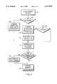
- FIG. 2is a flowchart for use in describing the operation of the system of FIG. 1.
- FIG. 1is a highly schematic diagram of one preferred embodiment 10 of the patient monitoring system of the present invention.
- System 10includes an ECG and arterial pressure (AP) monitoring device 12 that is connected to, but electrically insulated from, a remote processor 20 by electrically non-conducting fiber optic-based links 15, 17.
- Device 12includes a plurality of electrode leads 64, 66, 68 and an AP transducer 70 that are attached by conventional means (e.g., adhesive tape, not shown) to the chest of a patient so as to permit the heart activity (i.e., ECG waveform and arterial blood pressure) of the patient to be monitored by the monitoring device 12.
- ECG and arterial pressure (AP) monitoring device 12that is connected to, but electrically insulated from, a remote processor 20 by electrically non-conducting fiber optic-based links 15, 17.
- Device 12includes a plurality of electrode leads 64, 66, 68 and an AP transducer 70 that are attached by conventional means (e.g., adhesive tape, not shown) to the chest of a
- Each lead 64, 66, 68is connected to the input of a respective amplifier 54, 56, 58.
- the outputs of the amplifiers 54, 56, 58are connected to respective input channels of analog-to-digital converter (ADC) 50.
- ADCanalog-to-digital converter
- the output of the transducer 70is connected to the input of amplifier 72.
- the output of amplifier 72is provided to another respective input channel of ADC 50.
- Amplifiers 54, 56, 58, 72provide to the respective input channels of the ADC 50 analog signals that are indicative of the status of the monitored anatomical condition (in this case, cardiac function) of the patient to which the leads 64, 66, 68 and transducer 70 are attached.
- ADC 50samples and holds the analog signals supplied to its input channels so as to convert them into digital signals representative of the patient's heart activity. These digital signals are supplied to the ECG Data Acquisition Controller 48.
- controller 48encodes the digital signals provided to it by the ADC 50, and supplies the encoded digital signals to photo-electric converter device 28. Controller 48 also supplies control signals to ADC 50 and controllable switches 60, 62 to control operation of the ADC 50, and the states of the switches 60, 62 (i.e., whether the switches 60, 62 are opened or closed), respectively.
- Power supply system 52is coupled, and supplies appropriate actuating power (i.e., voltage and current) to, each of the ADC 50, controller 48, and transducer 70.
- actuating poweri.e., voltage and current
- supply of actuating power from the supply 52is controlled by the state of the switch 62. That is, when the switch 62 is closed, actuating power is supplied from supply 52 to the pressure transducer 70, while when switch 62 is open, such actuating power is not supplied to the transducer 70.
- Switch 60is coupled to both a "floating" (i.e., non-earth) ground potential and respective reset inputs of the amplifiers 54, 56, 58 such that when switch 60 is momentarily closed and thereafter reopened, a reset signal is supplied to each of the amplifiers 54, 56, 58 that causes these amplifiers 54, 56, 58 to reset their internal states to predetermined initialization states (i.e., the states that the amplifiers 54, 56, 58 are configured to enter immediately upon being powered-up after being powered-down).
- a "floating"i.e., non-earth
- Electrical power supplied by the power supply system 52 to power the monitoring device 12is transmitted from the remote system 20 to the system 52 via the link 17. More specifically, laser light generated by a laser light emitting diode 30 is transmitted via link 17 to a photo-electric converter circuit comprising light-to-voltage converter 26, amplifier 40, and a voltage regulating circuit comprising diode 42 and "holdup" capacitor 44 (e.g., having a capacitance of 100 microfarads).
- the photo-electric converter 26converts the laser light received via link 17 into electric power and control signals.
- Power supply system 52comprises conventional circuitry (e.g., DC level converting and power distribution circuitry, etc.) for converting the electric power signals received from the photo-electric converter circuit 26 into signals of appropriate voltage and current levels to power the components 48, 50, 70.
- the electric control signalsare supplied to the ECG controller 48 for controlling operation of the controller 48.
- amplifiers 54, 56, 58, 72are also powered by the supply 52.
- Converter 26comprises a two-terminal laser power converter cell. One of the terminals of converter 26 is connected to the "floating" ground potential, and the other terminal is connected, in parallel, to the input of amplifier 40 and the anode of diode 42. The cathode of diode 42 is connected to the positive terminal of capacitor 44, and the negative terminal of the capacitor 44 is connected to the floating ground potential. The positive terminal of the capacitor 44 is also connected to the power supply 52. The output of amplifier 40 is connected to a data input line of the controller 48.
- Converter 26is coupled via conventional optical coupler means 24 to one end of fiber optical cable 16; the opposite end of cable 16 is coupled, via another conventional optical coupler means 22 to a laser light emitting diode 30 so as to permit laser light emitted by the diode 30 to be transmitted via the cable 16 and coupler 24 to cell 26.
- the cathode of the diode 30is coupled to earth ground, while the anode of the diode 30 is coupled to the output of buffer 38.
- the input of buffer 38is coupled to a signal output line of processor 20.
- Processor 20supplies, via the buffer 38, electric signals to the diode 30 which are used to power and control operation of the monitoring device 12.
- the diode 30is excited by these electric signals to generate laser light signals, which are supplied via link 17 to receiving light-to-voltage converter 26, that are representative of the electric signals from the processor 20.
- Converter 28comprises a light emitting diode whose anode is connected to the controller 48 so as to receive the encoded data signals from the controller 48.
- the cathode of the diode 28is connected to the floating ground potential.
- Diode 28generates light signals representative of the encoded data signals supplied thereto from the controller 48.
- Diode 28is coupled to conventional optical coupling means 20 that permits the light signals generated by the diode 28 to be transmitted to the fiber optic cable 14, and thence, via another conventional optical coupling means 18 to receiving photo-electric converter 32.
- Converter 32comprises a photodiode whose anode is connected to earth ground and whose cathode is connected to the input of an amplifier 36.
- Diode 32converts the light signals received from the link 15 into the encoded digital signals supplied to the diode 28 by the controller 48. These encoded digital signals are amplified by the amplifier 36, and the amplified signals are supplied to the processor 20.
- a conventional user interface 34is also provided in system 10, which interface 34 is coupled to the processor 20.
- Interface 34may comprise a conventional personal computer system (e.g., an IBM-type, Intel 80X86-based personal computer system) that is configured to receive, store, and display (e.g., via a conventional graphical user interface) data supplied by the processor 20, and is also adapted to permit user input of commands to the processor 20 (e.g., via said graphical user interface).
- the processor 20 and interface 34are powered by a conventional user-actuable power supply (not shown) that is different from the power supply 52 used to power the monitoring device 12.
- the processor 20, interface 34, amplifier 36, buffer 38, and converters 30, 32are all located at a location 21 that is remote from the location 23 of the monitoring device 12, converters 26, 28, amplifier 40, diode 42 and capacitor 44.
- each of the amplifiers 40, 54, 56, 58, 72comprises one or more respective operational amplifiers (e.g., of the type having part number LMC 6464 manufactured by National Semiconductor Corporation of Santa Clara, Calif.) configured to amplify the respective signals input to them.
- the ADC 50may comprise a MAX147 integrated circuit chip manufactured by Maxim Integrated Products Inc. of Sunnyvale, Calif.
- Controller 48may comprise a 16LC84 integrated circuit chip available from Microchip Technology, Inc.
- the remote processor 20may comprise a 68HC16 integrated circuit chip available from Motorola, Inc. of Phoenix, Ariz. and associated program/data RAM and ROM memory.
- the remote processor 20may comprise a 68HC16 integrated circuit chip available from Motorola, Inc. of Phoenix, Ariz. and associated program/data RAM and ROM memory.
- Buffer 38may comprise an S16433 integrated circuit chip manufactured by Siliconix, Inc. of Santa Clara, Calif.
- amplifier 36may comprise an SFH551 integrated circuit chip available from Siemens, AG, of Kunststoff, Germany.
- the pressure transducer amplifier 72may be of a type manufactured by Analog Devices, Inc. of Norwood, Mass.
- Converter 26may comprise a laser power converter, designed to convert specific wavelengths of laser light (e.g., wavelength bands in the red or infrared areas of the spectrum) into electrical energy, of a type manufactured by Spire Corporation of Bedford, Mass.
- the leads 64, 66, 68 and transducer 70are secured to the patient's chest so as to permit the monitoring device 12 to monitor the patient's cardiac activity. Thereafter, the processor 20 and interface 34 are powered-up (e.g., via user activation of the power supply that powers processor 20 and interface 34). After the processor 20 and user interface 34 have been properly powered-up and initialized, in order to start monitoring the patient's cardiac function, a user (not shown) enters appropriate commands via the interface 34 for causing the system 10 to initiate such monitoring. These commands are transmitted to the processor 20, which in response thereto, generates pulse code modulated (PCM) electric signals which are supplied to buffer 38.
- PCMpulse code modulated
- the electric signals that are supplied from the processor 20 to the buffer 38control various aspects of the operation of the monitoring device 12, including whether the monitoring device 12 is powered-up or powered-down, and other aspects of said operation.
- the electrical signals that are supplied from the processor 20 to the buffer 38will be referred to as "electrical power and control signals.”
- Buffer 38is configured to electrically isolate the circuits of the processor 20 from the laser light emitting diode 30, and maintains the voltage level of the signals input to buffer 38 from the processor 20 while "boosting" (i.e., substantially increasing) the current level of those signals. That is, the signals output by the buffer 38 to the laser light emitting diode 30 are at the same respective voltage levels as the corresponding signals input to the buffer 38, but the signals output by the buffer 38 have a substantially greater current level than those corresponding signals. The output signals from the buffer 38 are then supplied to the laser light emitting diode 30.
- Diode 30converts the "boosted" power and control signals supplied thereto from the buffer 38 into laser light whose amplitude and power levels are related to the boosted power and control signals. These optical power and control signals are then transmitted by the link 17 to the light-to-voltage converter 26. The converter 26 recovers from the optical power and control signals the boosted electrical power and control signals from which they were generated, which recovered signals are then supplied in parallel to the amplifier 40 and diode 42. Diode 42 is biased so as to permit the reconverted signals to propagate to the power supply 52 and to capacitor 44, but to prevent signal propagation from these components 44, 52 to the diode 26 and amplifier 40.
- the signals supplied to the buffer 38 from the processor 20are PCM signals.
- PCM signalsdigital signal pulses of relatively longer or shorter durations are interpreted as data bits of different logic levels. For example, a data bit of logic "1" is encoded by a signal pulse (e.g., 2 microseconds) of relatively long duration, while a data bit of logic "0" is encoded by a pulse (e.g., 1 microsecond) of relatively shorter duration.
- the power and control signalsare PCM signals, there will be intermittent periods wherein the reconverted power and control signals will have zero amplitude. During these intermittent periods, charge previously stored in the capacitor 44 is discharged therefrom and supplied to the supply 52 for use in powering the monitoring device 12.
- the capacitor 44is charged by the recovered power and control signals.
- the electric energy supplied to the supply 52 from the cell 26 and capacitor 44is converted by the conventional circuitry of the supply 52 into respective voltage and current levels appropriate for powering the various components of the monitoring device 12, and are supplied to these components whereby to power-up the monitoring device 12.
- Controller 48is programmed such that, after the controller 48 has powered-up and initialized its internal registers, etc., controller 48 waits a predetermined time period (e.g., at least about 2.5 milliseconds) that has been empirically determined to be sufficient for the ADC 50 and amplifiers 54, 56, 58, 72 to stabilize after initial power-up, and thereafter, provides a data synchronization clock signal to ADC 50 to permit the controller 48 and ADC 50 to be able to exchange data and commands.
- the ADC 50provides to the controller 48 an acknowledgment signal that indicates that the ADC 50 is now ready, when commanded by the controller 48, to begin digitizing signals received from the amplifiers 54, 56, 58 and 72, and to supply the resulting digital signals to the controller 48.
- the controller 48In response to receipt of the acknowledgment signal from the ADC 50, the controller 48 generates PCM encoded, ready signals that indicate that the monitoring device 12 is now ready to begin monitoring the patient's cardiac functioning, and provides the encoded ready signal to the light emitting diode 28.
- the encoded electric ready signals supplied to the diode 28provide sufficient excitation energy to the diode 28 to cause the diode 28 to generate PCM light signals, corresponding to the PCM encoded, electric ready signals. These PCM light signals are transmitted via link 15 to receiving photodiode 32.
- Photodiode 32recovers from the PCM light signals that it receives the PCM electric ready signals, which ready signals are then amplified by amplifier 36 (e.g., to compensate for signal attenuation from processing by diodes 28, 32 and propagation through link 15) and are supplied to the processor 20.
- amplifier 36e.g., to compensate for signal attenuation from processing by diodes 28, 32 and propagation through link 15
- Processor 20decodes the PCM ready signals to generate a bit stream that is interpreted by the processor 20 as indicating that the monitoring device 12 is now ready to begin monitoring the patient's cardiac function.
- the processor 20then supplies appropriate commands to the interface 34 to cause the interface 34 to indicate to the user that system 10 is now ready to begin monitoring the patient's cardiac function, and to prompt the user to inform the system 10 as to the manner in which monitoring of the cardiac function is to be carried out by the system 10.
- the user prompt provided by the interface 34may request that the user provide commands via the interface 34 specifying which of the input channels of the ADC 50 are to be used to measure cardiac function, desired frequency of such measurements and measurements of patient AP, etc. Additionally, the interface 34 may also permit the user to command that the amplifiers 54, 56, 58 be reset, and/or to specify other commands.
- the commands input by the user via the interface 34 to the system 10are received by the processor 20.
- the processor 20In response to receipt of these commands, the processor 20 generates and supplies to the buffer 38 PCM power and control signals which may be decoded to recover these commands. These power and control signals are then processed by the buffer 38, diode 30, link 17, and cell 26 in the aforedescribed manner.
- the impedance of the circuit branch consisting of the diode 42, capacitor 44 and power supply 52, and the impedance of the circuit branch consisting of the amplifier 40 and controller 48are selected such that the power of the PCM signals transmitted from the converter 26 is split between these two branches in such a way that the power delivered to the latter circuit branch is several orders of magnitude less than that delivered to the former circuit branch. This permits the vast majority of power of the recovered power and control signals to be used to power the monitoring device 12, and prevents the controller 48 from becoming overloaded with excessive power from these PCM signals. Given the significantly reduced strength of the power and control signals provided to the latter branch, amplifier 40 is provided to permit same to be usable as control signals for controlling operation of the controller 48.
- the controller 48decodes PCM signals provided to it to reconstruct the commands that the processor 20 wishes the controller 48 to execute. After the controller 48 determines these commands, the controller 48 provides appropriate control signals to the ADC 50 and/or switches 60, 62 to carry out said commands, and after carrying them out, the controller 48 provides appropriate PCM acknowledgment signals to the processor 20 (via the diode 28, link 15, diode 32, and amplifier 36) to indicate that these commands have been carried out.
- the commands provided to the controller 48 from the processor 20may indicate that all of the input channels of the ADC 50 are to be used in monitoring the patient's cardiac function, and that measurements of heart activity and AP are to be made by the monitoring device 12 using a default measurement cycle (e.g., readings of heart activity measured via the leads 64, 66, 68 are to be taken every 1.25 milliseconds, and AP readings are to be taken every 10 milliseconds) that is preprogrammed into the controller 48. If such a default measurement cycle is commanded, the measurement process implemented by the controller 48 is as illustrated in FIG. 2.
- a default measurement cyclee.g., readings of heart activity measured via the leads 64, 66, 68 are to be taken every 1.25 milliseconds, and AP readings are to be taken every 10 milliseconds
- the controller 48in the default measurement cycle, the controller 48 generates measurement cycle interrupts every 1.25 milliseconds which trigger an interrupt processing routine whose execution begins, as shown, at block 100. After beginning execution of the routine, the controller 48 determines whether an interrupt counter variable (which is initialized to zero when the controller 48 powers up) is equal to six (see block 102), and if so, the controller 48 supplies a control signal to the switch 62 that causes the switch 62 to close so that power is supplied from supply 52 to the transducer 70 (see block 104). Prior to supply of this control signal, the transducer 70 is powered-down so as to minimize energy drain on supply 52.
- an interrupt counter variablewhich is initialized to zero when the controller 48 powers up
- the controller 48supplies a control signal to the switch 62 that causes the switch 62 to close so that power is supplied from supply 52 to the transducer 70 (see block 104). Prior to supply of this control signal, the transducer 70 is powered-down so as to minimize energy drain on supply 52.
- the controller 48commands all of the channels of the ADC 50 to be sampled and the signals being input thereto from the amplifiers 54, 56, 58 to be digitized (see block 112). These digitized signals are then supplied to the controller 48, which provides them, in the aforedescribed manner, as pulse code modulated signals, to the processor 20.
- the processor 20decodes the pulse code modulated signals to recover the digitized signals, and determines whether they are outside a predetermined range of expected values therefor that has been empirically determined to be indicative of normal operation of the monitoring device 12 (i.e., if any of the values of the digitized signals is outside of this range, the processor 20 determines that a failure condition, such as saturation of one of the amplifiers 54, 56, 58, has occurred in the monitoring device 12; see block 114). If such a failure condition is determined to exist, the processor 20 transmits appropriate PCM signals to the controller 48 to remedy the situation by causing the controller 48 to control the reset switch 60 to provide the reset signal to the amplifiers 54, 56, 58.
- a failure conditionsuch as saturation of one of the amplifiers 54, 56, 58
- the processor 20determines that an ECG "lockup" failure condition is present, and remedies this by temporarily ceasing provision of power and control signals to the monitoring device 12 so as to temporarily power-down, and thereafter, power-up the ECG12 into the ECG's initial power-up state. Otherwise, if the processor 20 does not take action to remedy presence of a failure condition in the monitoring device 12, the controller's interrupt routine terminates after incrementing the interrupt counter variable.
- controller 48determines whether the interrupt counter variable is equal to eight (see block 106). If at block 106, the counter variable is not equal to eight, the interrupt process branches to block 112.
- the controller 48supplies control signals to the ADC 50 to digitize the AP signal being supplied from the amplifier 72, and to supply this digitized AP signal to the controller 48.
- the controllerthen opens the switch 62, thereby deactivating the transducer 70, and resets the interrupt counter variable to zero (see blocks 108 and 110).
- the controller 48then encodes the digitized AP signal supplied from the ADC 50 into PCM signal format, and supplies this PCM AP data signal to the processor 20.
- Data values(i.e., representing cardiac activity and AP), decoded by the processor 20 from the PCM data signals sent from the monitoring device 12, are processed by the processor 20 to put them into a format suitable for processing by the interface 34 (e.g., for display via the graphical user interface of the interface 34). These processed signals are then supplied to the interface 34, which generates therefrom a user-appreciable display of the measurements of the patient's cardiac function taken using the monitoring device 12 and/or undertakes additional conventional processing.
- the value to which the interrupt counter variable is compared at blocks 102 and 106, and the frequency of measurement interruptsmay be provided to the controller 48 by the PCM signals from the processor 20.
- the processor 20may be commanded by the processor 20 to be implemented by the monitoring device 12.
- controller 48may comprise non-volatile memory storing preprogramed calibration constants related to operation of the amplifiers 54, 56, 58, 72. These calibration constants may be provided, upon initial power-up of the monitoring device 12, to the processor 20 to permit the processor 20 to appropriately adjust (i.e., normalize) data from the channels of the ADC 50 so as to compensate for differences in measurement data from those channels due to relative performance differences between the amplifiers 54, 56, 58, 72.
- these calibration constantsmay include information that may be used by the processor 20 to appropriately adjust the measurements being received from the monitoring device 12 to account for changes in performance (e.g., gain characteristics, etc.) of the amplifiers 54, 56, 58, 72 that may result from aging of amplifiers 54, 56, 58, 72, ambient temperature changes, etc.
- changes in performancee.g., gain characteristics, etc.
- the factor by which the output signals of the buffer 38 are boosted relative to the signals input to the buffer 38is empirically determined so as to permit the portion of the reconverted power and control signals provided to supply 52 to be of sufficient average power to power the monitoring device 12 (e.g., about 30 mW).
- the size of capacitor 44is chosen so as to permit the capacitor 44 to be able to store sufficient charge given the duty cycle of the PCM power and control signals to power the monitoring device 12 when the PCM power and control signals have zero amplitude.
- fiber optic links in system 10dramatically reduces (e.g., by several orders of magnitude) the parasitic capacitance generated in the system 10 compared to the prior art. More specifically, since the fiberopticbased links of system 10 are substantially non-conducting, this permits the system 10 to exhibit greatly improved resistance to noise injection to system 10 from ambient electromagnetic energy and improved patient isolation characteristic compared to prior art systems which implement patient isolation techniques based upon transformers and miniature optocouplers.
- the processor 20has been described as providing electrical signals that both supply power to the monitoring device 12 and control operation of the monitoring device 12, if system 10 is appropriately modified, the power supply 52 may include appropriate conventional DC power supply means (e.g., batteries, etc.) for supplying power to the monitoring device 12 without requiring supply of power from the processor 20.
- appropriate conventional DC power supply meanse.g., batteries, etc.
- the measurement process of FIG. 2may instead be implemented by the processor 20.
- the processor 20may be programmed to carry out the measurement cycle interrupts and interrupt processing routine, previously described as being carried out by controller 48, based upon the user-input commands provided to the processor 20 via the interface 34.
- the processor 20may issue electrical power and control signals to cause the controller 48 to appropriately control the switches 60, 62, ADC 50, etc. to carry out measurements of AP and ECG activity and to supply same to the processor 20, supply reset signals to amplifiers 54, 56, 58, etc., as needed, to carry out the processing at steps 104, 108, 112, and 116 of the interrupt service routine.
- this modificationpermits system 10 to exhibit greater design modularlity.
Landscapes
- Health & Medical Sciences (AREA)
- Life Sciences & Earth Sciences (AREA)
- Engineering & Computer Science (AREA)
- Biomedical Technology (AREA)
- Medical Informatics (AREA)
- Computer Networks & Wireless Communication (AREA)
- Biophysics (AREA)
- Pathology (AREA)
- Physiology (AREA)
- Heart & Thoracic Surgery (AREA)
- Physics & Mathematics (AREA)
- Molecular Biology (AREA)
- Surgery (AREA)
- Animal Behavior & Ethology (AREA)
- General Health & Medical Sciences (AREA)
- Public Health (AREA)
- Veterinary Medicine (AREA)
- Measuring And Recording Apparatus For Diagnosis (AREA)
Abstract
Description
Claims (13)
Priority Applications (1)
| Application Number | Priority Date | Filing Date | Title |
|---|---|---|---|
| US09/157,762US6117076A (en) | 1998-09-21 | 1998-09-21 | Patient monitoring system and method |
Applications Claiming Priority (1)
| Application Number | Priority Date | Filing Date | Title |
|---|---|---|---|
| US09/157,762US6117076A (en) | 1998-09-21 | 1998-09-21 | Patient monitoring system and method |
Publications (1)
| Publication Number | Publication Date |
|---|---|
| US6117076Atrue US6117076A (en) | 2000-09-12 |
Family
ID=22565170
Family Applications (1)
| Application Number | Title | Priority Date | Filing Date |
|---|---|---|---|
| US09/157,762Expired - LifetimeUS6117076A (en) | 1998-09-21 | 1998-09-21 | Patient monitoring system and method |
Country Status (1)
| Country | Link |
|---|---|
| US (1) | US6117076A (en) |
Cited By (32)
| Publication number | Priority date | Publication date | Assignee | Title |
|---|---|---|---|---|
| US6351678B1 (en)* | 1997-11-07 | 2002-02-26 | Hill-Rom Services, Inc. | Medical equipment controller |
| US6360117B1 (en)* | 1999-05-24 | 2002-03-19 | Terry B. J. Kuo | Electrocardiogram signal collecting apparatus |
| US20020084698A1 (en)* | 2000-11-20 | 2002-07-04 | Kelly Clifford Mark | Electrically isolated power and signal coupler system for a patient connected device |
| US6897788B2 (en) | 2000-04-18 | 2005-05-24 | Motorola, Inc. | Wireless system protocol for telemetry monitoring |
| US6987965B2 (en) | 2000-04-18 | 2006-01-17 | Motorola, Inc. | Programmable wireless electrode system for medical monitoring |
| US7010369B2 (en) | 1997-11-07 | 2006-03-07 | Hill-Rom Services, Inc. | Medical equipment controller |
| US7197357B2 (en) | 2001-07-17 | 2007-03-27 | Life Sync Corporation | Wireless ECG system |
| US7215991B2 (en) | 1993-09-04 | 2007-05-08 | Motorola, Inc. | Wireless medical diagnosis and monitoring equipment |
| US20070106247A1 (en)* | 2005-10-21 | 2007-05-10 | Ceeben Systems, Inc. | Method and apparatus for peritoneal hypothermia and/or resuscitation |
| US20070141869A1 (en)* | 2003-08-21 | 2007-06-21 | Hill-Rom Services, Inc. | Plug and receptacle having wired and wireless coupling |
| US7272428B2 (en) | 2000-07-18 | 2007-09-18 | Motorola, Inc. | Wireless electrocardiograph system and method |
| US20090052677A1 (en)* | 2007-08-20 | 2009-02-26 | Smith Christopher M | Sound monitoring, data collection and advisory system |
| US7933642B2 (en) | 2001-07-17 | 2011-04-26 | Rud Istvan | Wireless ECG system |
| US8100880B2 (en) | 2007-04-05 | 2012-01-24 | Velomedix, Inc. | Automated therapy system and method |
| US20120108917A1 (en)* | 2008-12-15 | 2012-05-03 | Corventis, Inc. | Patient monitoring systems and methods |
| US8251904B2 (en) | 2005-06-09 | 2012-08-28 | Roche Diagnostics Operations, Inc. | Device and method for insulin dosing |
| US8258973B2 (en) | 2005-02-11 | 2012-09-04 | Hill-Rom Services, Inc. | Transferable patient care equipment support |
| US8439960B2 (en) | 2007-07-09 | 2013-05-14 | Velomedix, Inc. | Hypothermia devices and methods |
| US9129054B2 (en) | 2012-09-17 | 2015-09-08 | DePuy Synthes Products, Inc. | Systems and methods for surgical and interventional planning, support, post-operative follow-up, and, functional recovery tracking |
| US9622670B2 (en) | 2010-07-09 | 2017-04-18 | Potrero Medical, Inc. | Method and apparatus for pressure measurement |
| US10137257B2 (en) | 2016-11-30 | 2018-11-27 | Belmont Instrument, Llc | Slack-time heating system for blood and fluid warming |
| US10395769B2 (en) | 2015-12-16 | 2019-08-27 | Hill-Rom Services, Inc. | Patient care devices with local indication of correspondence and power line interconnectivity |
| US10485936B2 (en) | 2016-11-30 | 2019-11-26 | Belmont Instrument, Llc | Rapid infuser with advantageous flow path for blood and fluid warming |
| US10507292B2 (en) | 2016-11-30 | 2019-12-17 | Belmont Instrument, Llc | Rapid infuser with vacuum release valve |
| US11000407B2 (en) | 2007-08-07 | 2021-05-11 | Belmont Instrument, Llc | Hyperthermia, system, method, and components |
| US11294407B2 (en) | 2001-04-27 | 2022-04-05 | Roche Diabetes Care, Inc. | Device and method for insulin dosing |
| US11446177B2 (en) | 2005-10-21 | 2022-09-20 | Theranova, Llc | Method and apparatus for peritoneal oxygenation |
| WO2023148112A1 (en)* | 2022-02-02 | 2023-08-10 | Koninklijke Philips N.V. | System for monitoring electrocardiogram pulses using virtual ground |
| WO2024056650A1 (en)* | 2022-09-14 | 2024-03-21 | Koninklijke Philips N.V. | Voltage-to-frequency electrocardiogram measurement node |
| US12186241B2 (en) | 2021-01-22 | 2025-01-07 | Hill-Rom Services, Inc. | Time-based wireless pairing between a medical device and a wall unit |
| US12279999B2 (en) | 2021-01-22 | 2025-04-22 | Hill-Rom Services, Inc. | Wireless configuration and authorization of a wall unit that pairs with a medical device |
| US12321824B1 (en)* | 2020-01-08 | 2025-06-03 | Liberty Mutual Insurance Company | Pipelined machine learning frameworks |
Citations (5)
| Publication number | Priority date | Publication date | Assignee | Title |
|---|---|---|---|---|
| EP0059172A1 (en)* | 1981-02-19 | 1982-09-01 | Maria Villani | Device for detecting bioelectric signals, in particular electrocardiac signals |
| US4694837A (en)* | 1985-08-09 | 1987-09-22 | Picker International, Inc. | Cardiac and respiratory gated magnetic resonance imaging |
| US4742831A (en)* | 1985-11-21 | 1988-05-10 | Siemens-Pacesetter, Inc. | Selection and isolation apparatus for use with ECG device |
| US5307817A (en)* | 1989-01-27 | 1994-05-03 | Medese Ag | Biotelemetry method for the transmission of bioelectric potential defferences, and a device for the transmission of ECG signals |
| US5311873A (en)* | 1992-08-28 | 1994-05-17 | Ecole Polytechnique | Comparative analysis of body surface potential distribution during cardiac pacing |
- 1998
- 1998-09-21USUS09/157,762patent/US6117076A/ennot_activeExpired - Lifetime
Patent Citations (5)
| Publication number | Priority date | Publication date | Assignee | Title |
|---|---|---|---|---|
| EP0059172A1 (en)* | 1981-02-19 | 1982-09-01 | Maria Villani | Device for detecting bioelectric signals, in particular electrocardiac signals |
| US4694837A (en)* | 1985-08-09 | 1987-09-22 | Picker International, Inc. | Cardiac and respiratory gated magnetic resonance imaging |
| US4742831A (en)* | 1985-11-21 | 1988-05-10 | Siemens-Pacesetter, Inc. | Selection and isolation apparatus for use with ECG device |
| US5307817A (en)* | 1989-01-27 | 1994-05-03 | Medese Ag | Biotelemetry method for the transmission of bioelectric potential defferences, and a device for the transmission of ECG signals |
| US5311873A (en)* | 1992-08-28 | 1994-05-17 | Ecole Polytechnique | Comparative analysis of body surface potential distribution during cardiac pacing |
Non-Patent Citations (7)
| Title |
|---|
| "The Bard® TransAct™ System for Aortic Counterpulsation Therapy H-800 Intra-Aortic Balloon Pump" Service Manual, ©1993, V.1-V.3. |
| "Transformer Coupled Isolation Amplifier", Linear Products, Burr-Brown ®, ©1996, pp. 5.290-5.292, 5.295-5.296 5.300-5.304. |
| Schematic, ECG & Pressure Amp, Belmont Instrument Corp, Drawing No. DPBP 444, (three sheets) 1992 1998.* |
| Schematic, ECG & Pressure Amp, Belmont Instrument Corp, Drawing No. DPBP-444, (three sheets) 1992-1998. |
| Spire Laser Power Converter Data Sheet.* |
| The Bard TransAct System for Aortic Counterpulsation Therapy H 800 Intra Aortic Balloon Pump Service Manual, 1993, V.1 V.3.* |
| Transformer Coupled Isolation Amplifier , Linear Products, Burr Brown , 1996, pp. 5.290 5.292, 5.295 5.296 5.300 5.304.* |
Cited By (60)
| Publication number | Priority date | Publication date | Assignee | Title |
|---|---|---|---|---|
| US8771184B2 (en) | 1993-09-04 | 2014-07-08 | Body Science Llc | Wireless medical diagnosis and monitoring equipment |
| US7215991B2 (en) | 1993-09-04 | 2007-05-08 | Motorola, Inc. | Wireless medical diagnosis and monitoring equipment |
| US7010369B2 (en) | 1997-11-07 | 2006-03-07 | Hill-Rom Services, Inc. | Medical equipment controller |
| US6560492B2 (en) | 1997-11-07 | 2003-05-06 | Hill-Rom Services, Inc. | Medical equipment controller |
| US6351678B1 (en)* | 1997-11-07 | 2002-02-26 | Hill-Rom Services, Inc. | Medical equipment controller |
| US6360117B1 (en)* | 1999-05-24 | 2002-03-19 | Terry B. J. Kuo | Electrocardiogram signal collecting apparatus |
| US7171166B2 (en) | 2000-04-18 | 2007-01-30 | Motorola Inc. | Programmable wireless electrode system for medical monitoring |
| US6987965B2 (en) | 2000-04-18 | 2006-01-17 | Motorola, Inc. | Programmable wireless electrode system for medical monitoring |
| US6897788B2 (en) | 2000-04-18 | 2005-05-24 | Motorola, Inc. | Wireless system protocol for telemetry monitoring |
| US7272428B2 (en) | 2000-07-18 | 2007-09-18 | Motorola, Inc. | Wireless electrocardiograph system and method |
| US6819013B2 (en) | 2000-11-20 | 2004-11-16 | Draeger Medical Systems, Inc. | Electrically isolated power and signal coupler system for a patient connected device |
| US20020084698A1 (en)* | 2000-11-20 | 2002-07-04 | Kelly Clifford Mark | Electrically isolated power and signal coupler system for a patient connected device |
| US11294407B2 (en) | 2001-04-27 | 2022-04-05 | Roche Diabetes Care, Inc. | Device and method for insulin dosing |
| US7933642B2 (en) | 2001-07-17 | 2011-04-26 | Rud Istvan | Wireless ECG system |
| US7197357B2 (en) | 2001-07-17 | 2007-03-27 | Life Sync Corporation | Wireless ECG system |
| US8255041B2 (en) | 2001-07-17 | 2012-08-28 | Lifesync Corporation | Wireless ECG system |
| US8727804B2 (en) | 2003-08-21 | 2014-05-20 | Hill-Rom Services, Inc. | Combined power and data cord and receptacle |
| US10206837B2 (en) | 2003-08-21 | 2019-02-19 | Hill-Rom Services, Inc. | Hospital bed and room communication modules |
| US9925104B2 (en) | 2003-08-21 | 2018-03-27 | Hill-Rom Services, Inc. | Hospital bed and room communication modules |
| US9572737B2 (en) | 2003-08-21 | 2017-02-21 | Hill-Rom Services, Inc. | Hospital bed having communication modules |
| US9142923B2 (en) | 2003-08-21 | 2015-09-22 | Hill-Rom Services, Inc. | Hospital bed having wireless data and locating capability |
| US20070141869A1 (en)* | 2003-08-21 | 2007-06-21 | Hill-Rom Services, Inc. | Plug and receptacle having wired and wireless coupling |
| US7399205B2 (en) | 2003-08-21 | 2008-07-15 | Hill-Rom Services, Inc. | Plug and receptacle having wired and wireless coupling |
| US8272892B2 (en) | 2003-08-21 | 2012-09-25 | Hill-Rom Services, Inc. | Hospital bed having wireless data capability |
| US8258973B2 (en) | 2005-02-11 | 2012-09-04 | Hill-Rom Services, Inc. | Transferable patient care equipment support |
| US8251904B2 (en) | 2005-06-09 | 2012-08-28 | Roche Diagnostics Operations, Inc. | Device and method for insulin dosing |
| US10311209B2 (en) | 2005-06-09 | 2019-06-04 | Roche Diabetes Care, Inc. | Device and method for insulin dosing |
| US8672884B2 (en) | 2005-10-21 | 2014-03-18 | Velomedix, Inc. | Method and apparatus for peritoneal hypothermia and/or resuscitation |
| US11446177B2 (en) | 2005-10-21 | 2022-09-20 | Theranova, Llc | Method and apparatus for peritoneal oxygenation |
| US20070106247A1 (en)* | 2005-10-21 | 2007-05-10 | Ceeben Systems, Inc. | Method and apparatus for peritoneal hypothermia and/or resuscitation |
| US8480648B2 (en) | 2007-04-05 | 2013-07-09 | Velomedix, Inc. | Automated therapy system and method |
| US8100880B2 (en) | 2007-04-05 | 2012-01-24 | Velomedix, Inc. | Automated therapy system and method |
| US11800992B2 (en) | 2007-04-05 | 2023-10-31 | Theranova, Llc | Device and method for safe access and automated therapy |
| US8439960B2 (en) | 2007-07-09 | 2013-05-14 | Velomedix, Inc. | Hypothermia devices and methods |
| US11000407B2 (en) | 2007-08-07 | 2021-05-11 | Belmont Instrument, Llc | Hyperthermia, system, method, and components |
| US20090052677A1 (en)* | 2007-08-20 | 2009-02-26 | Smith Christopher M | Sound monitoring, data collection and advisory system |
| US8194866B2 (en) | 2007-08-20 | 2012-06-05 | Smith Christopher M | Sound monitoring, data collection and advisory system |
| US8823490B2 (en)* | 2008-12-15 | 2014-09-02 | Corventis, Inc. | Patient monitoring systems and methods |
| US20120108917A1 (en)* | 2008-12-15 | 2012-05-03 | Corventis, Inc. | Patient monitoring systems and methods |
| US9445719B2 (en) | 2008-12-15 | 2016-09-20 | Medtronic Monitoring, Inc. | Patient monitoring systems and methods |
| US10758135B2 (en) | 2010-07-09 | 2020-09-01 | Potrero Medical, Inc. | Method and apparatus for pressure measurement |
| US9931044B2 (en) | 2010-07-09 | 2018-04-03 | Potrero Medical, Inc. | Method and apparatus for pressure measurement |
| US9622670B2 (en) | 2010-07-09 | 2017-04-18 | Potrero Medical, Inc. | Method and apparatus for pressure measurement |
| US11923068B2 (en) | 2012-09-17 | 2024-03-05 | DePuy Synthes Products, Inc. | Systems and methods for surgical and interventional planning, support, post-operative follow-up, and functional recovery tracking |
| US11798676B2 (en) | 2012-09-17 | 2023-10-24 | DePuy Synthes Products, Inc. | Systems and methods for surgical and interventional planning, support, post-operative follow-up, and functional recovery tracking |
| US10595844B2 (en) | 2012-09-17 | 2020-03-24 | DePuy Synthes Products, Inc. | Systems and methods for surgical and interventional planning, support, post-operative follow-up, and functional recovery tracking |
| US9700292B2 (en) | 2012-09-17 | 2017-07-11 | DePuy Synthes Products, Inc. | Systems and methods for surgical and interventional planning, support, post-operative follow-up, and functional recovery tracking |
| US11749396B2 (en) | 2012-09-17 | 2023-09-05 | DePuy Synthes Products, Inc. | Systems and methods for surgical and interventional planning, support, post-operative follow-up, and, functional recovery tracking |
| US10166019B2 (en) | 2012-09-17 | 2019-01-01 | DePuy Synthes Products, Inc. | Systems and methods for surgical and interventional planning, support, post-operative follow-up, and, functional recovery tracking |
| US9129054B2 (en) | 2012-09-17 | 2015-09-08 | DePuy Synthes Products, Inc. | Systems and methods for surgical and interventional planning, support, post-operative follow-up, and, functional recovery tracking |
| US10395769B2 (en) | 2015-12-16 | 2019-08-27 | Hill-Rom Services, Inc. | Patient care devices with local indication of correspondence and power line interconnectivity |
| US10507292B2 (en) | 2016-11-30 | 2019-12-17 | Belmont Instrument, Llc | Rapid infuser with vacuum release valve |
| US10137257B2 (en) | 2016-11-30 | 2018-11-27 | Belmont Instrument, Llc | Slack-time heating system for blood and fluid warming |
| US11872382B2 (en) | 2016-11-30 | 2024-01-16 | Belmont Instrument, Llc | Rapid infuser with advantageous flow path for blood and fluid warming, and associated components, systems, and methods |
| US10485936B2 (en) | 2016-11-30 | 2019-11-26 | Belmont Instrument, Llc | Rapid infuser with advantageous flow path for blood and fluid warming |
| US12321824B1 (en)* | 2020-01-08 | 2025-06-03 | Liberty Mutual Insurance Company | Pipelined machine learning frameworks |
| US12186241B2 (en) | 2021-01-22 | 2025-01-07 | Hill-Rom Services, Inc. | Time-based wireless pairing between a medical device and a wall unit |
| US12279999B2 (en) | 2021-01-22 | 2025-04-22 | Hill-Rom Services, Inc. | Wireless configuration and authorization of a wall unit that pairs with a medical device |
| WO2023148112A1 (en)* | 2022-02-02 | 2023-08-10 | Koninklijke Philips N.V. | System for monitoring electrocardiogram pulses using virtual ground |
| WO2024056650A1 (en)* | 2022-09-14 | 2024-03-21 | Koninklijke Philips N.V. | Voltage-to-frequency electrocardiogram measurement node |
Similar Documents
| Publication | Publication Date | Title |
|---|---|---|
| US6117076A (en) | Patient monitoring system and method | |
| US3742947A (en) | Optically isolated electro-medical device | |
| US20010023361A1 (en) | Implantable device with optical telemetry | |
| CA2120243C (en) | Compressed storage of data in cardiac pacemakers | |
| US3727616A (en) | Electronic system for the stimulation of biological systems | |
| US5899928A (en) | Descriptive transtelephonic pacing intervals for use by an emplantable pacemaker | |
| US4877032A (en) | Sensor arrangement for the control of implantable devices | |
| CA1120549A (en) | Implantable demand pacemaker | |
| US6711440B2 (en) | MRI-compatible medical device with passive generation of optical sensing signals | |
| US4187854A (en) | Implantable demand pacemaker and monitor | |
| EP1986738B1 (en) | Class-e radio frequency power amplifier with feedback control | |
| US20030069486A1 (en) | Low power pulse oximeter | |
| US5217009A (en) | Compact biomedical pulsed signal generator for bone tissue stimulation | |
| US6731979B2 (en) | Pulse width cardiac pacing apparatus | |
| US7203551B2 (en) | Implantable lead-based sensor powered by piezoelectric transformer | |
| US9357944B2 (en) | Impedance measurement and demodulation using implantable device | |
| US6195585B1 (en) | Remote monitoring of implantable cochlear stimulator | |
| EP0171967A2 (en) | Electrosurgical generator | |
| EP0570674A1 (en) | Device for reducing power consumption in medical electrical equipment which is implantable in the human body | |
| EP2049911B1 (en) | Transmission path for use in rf fields providing reduced rf heating | |
| CA2266680A1 (en) | Data communication system for control of transcutaneous energy transmission to an implantable medical device | |
| US4677986A (en) | Unsaturable sense amplifier for pacer system analyzer | |
| JPH06142113A (en) | Electric surgery appliance and electromagnetic wave fault preventing device to medical electronic apparatus by electric surgery appliance | |
| CN101601890A (en) | Be used for pace-making and the wave filter that melts simultaneously | |
| JPH04314423A (en) | Electromyograph with data possible to transmit without using metallic conductor |
Legal Events
| Date | Code | Title | Description |
|---|---|---|---|
| AS | Assignment | Owner name:BELMONT INSTRUMENT CORPORATION, MASSACHUSETTS Free format text:ASSIGNMENT OF ASSIGNORS INTEREST;ASSIGNOR:CASSIDY, DAVID;REEL/FRAME:009541/0948 Effective date:19981023 | |
| STCF | Information on status: patent grant | Free format text:PATENTED CASE | |
| AS | Assignment | Owner name:ARROW INTERNATIONAL, INC., PENNSYLVANIA Free format text:ASSIGNMENT OF ASSIGNORS INTEREST;ASSIGNOR:BELMONT INSTRUMENT CORPORATION;REEL/FRAME:011620/0592 Effective date:20010116 | |
| AS | Assignment | Owner name:ARROW INTERNATIONAL INVESTMENT CORP., DELAWARE Free format text:ASSIGNMENT OF ASSIGNORS INTEREST;ASSIGNOR:ARROW INTERNATIONAL, INC.;REEL/FRAME:013774/0812 Effective date:20030128 | |
| FEPP | Fee payment procedure | Free format text:PAT HOLDER NO LONGER CLAIMS SMALL ENTITY STATUS, ENTITY STATUS SET TO UNDISCOUNTED (ORIGINAL EVENT CODE: STOL); ENTITY STATUS OF PATENT OWNER: LARGE ENTITY | |
| REMI | Maintenance fee reminder mailed | ||
| FPAY | Fee payment | Year of fee payment:4 | |
| SULP | Surcharge for late payment | ||
| FEPP | Fee payment procedure | Free format text:PAYOR NUMBER ASSIGNED (ORIGINAL EVENT CODE: ASPN); ENTITY STATUS OF PATENT OWNER: LARGE ENTITY | |
| FPAY | Fee payment | Year of fee payment:8 | |
| FPAY | Fee payment | Year of fee payment:12 | |
| AS | Assignment | Owner name:ARROW INTERNATIONAL INVESTMENT CORP., DELAWARE Free format text:CHARGE OF PATENT OWNER ADDRESS;ASSIGNOR:ARROW INTERNATIONAL INVESTMENT CORP.;REEL/FRAME:035771/0630 Effective date:20080414 | |
| AS | Assignment | Owner name:JPMORGAN CHASE BANK, N.A., AS ADMINISTRATIVE AGENT Free format text:SECURITY INTEREST;ASSIGNOR:ARROW INTERNATIONAL INVESTMENT CORP.;REEL/FRAME:041759/0707 Effective date:20170217 | |
| AS | Assignment | Owner name:ARROW INTERNATIONAL, INC., PENNSYLVANIA Free format text:MERGER;ASSIGNOR:ARROW INTERNATIONAL INVESTMENT CORP.;REEL/FRAME:049348/0690 Effective date:20181227 |