US6116926A - Connector for electrical isolation in a condensed area - Google Patents
Connector for electrical isolation in a condensed areaDownload PDFInfo
- Publication number
- US6116926A US6116926AUS09/295,504US29550499AUS6116926AUS 6116926 AUS6116926 AUS 6116926AUS 29550499 AUS29550499 AUS 29550499AUS 6116926 AUS6116926 AUS 6116926A
- Authority
- US
- United States
- Prior art keywords
- contact
- mating
- ground
- receptacle
- contacts
- Prior art date
- Legal status (The legal status is an assumption and is not a legal conclusion. Google has not performed a legal analysis and makes no representation as to the accuracy of the status listed.)
- Expired - Lifetime
Links
Images


Classifications
- H—ELECTRICITY
- H01—ELECTRIC ELEMENTS
- H01R—ELECTRICALLY-CONDUCTIVE CONNECTIONS; STRUCTURAL ASSOCIATIONS OF A PLURALITY OF MUTUALLY-INSULATED ELECTRICAL CONNECTING ELEMENTS; COUPLING DEVICES; CURRENT COLLECTORS
- H01R13/00—Details of coupling devices of the kinds covered by groups H01R12/70 or H01R24/00 - H01R33/00
- H01R13/646—Details of coupling devices of the kinds covered by groups H01R12/70 or H01R24/00 - H01R33/00 specially adapted for high-frequency, e.g. structures providing an impedance match or phase match
- H01R13/6461—Means for preventing cross-talk
- H01R13/6471—Means for preventing cross-talk by special arrangement of ground and signal conductors, e.g. GSGS [Ground-Signal-Ground-Signal]
- H—ELECTRICITY
- H01—ELECTRIC ELEMENTS
- H01R—ELECTRICALLY-CONDUCTIVE CONNECTIONS; STRUCTURAL ASSOCIATIONS OF A PLURALITY OF MUTUALLY-INSULATED ELECTRICAL CONNECTING ELEMENTS; COUPLING DEVICES; CURRENT COLLECTORS
- H01R13/00—Details of coupling devices of the kinds covered by groups H01R12/70 or H01R24/00 - H01R33/00
- H01R13/648—Protective earth or shield arrangements on coupling devices, e.g. anti-static shielding
- H01R13/658—High frequency shielding arrangements, e.g. against EMI [Electro-Magnetic Interference] or EMP [Electro-Magnetic Pulse]
- H01R13/6581—Shield structure
- H01R13/6585—Shielding material individually surrounding or interposed between mutually spaced contacts
- H01R13/6586—Shielding material individually surrounding or interposed between mutually spaced contacts for separating multiple connector modules
- H—ELECTRICITY
- H01—ELECTRIC ELEMENTS
- H01R—ELECTRICALLY-CONDUCTIVE CONNECTIONS; STRUCTURAL ASSOCIATIONS OF A PLURALITY OF MUTUALLY-INSULATED ELECTRICAL CONNECTING ELEMENTS; COUPLING DEVICES; CURRENT COLLECTORS
- H01R12/00—Structural associations of a plurality of mutually-insulated electrical connecting elements, specially adapted for printed circuits, e.g. printed circuit boards [PCB], flat or ribbon cables, or like generally planar structures, e.g. terminal strips, terminal blocks; Coupling devices specially adapted for printed circuits, flat or ribbon cables, or like generally planar structures; Terminals specially adapted for contact with, or insertion into, printed circuits, flat or ribbon cables, or like generally planar structures
- H01R12/70—Coupling devices
- H01R12/71—Coupling devices for rigid printing circuits or like structures
- H01R12/72—Coupling devices for rigid printing circuits or like structures coupling with the edge of the rigid printed circuits or like structures
- H01R12/722—Coupling devices for rigid printing circuits or like structures coupling with the edge of the rigid printed circuits or like structures coupling devices mounted on the edge of the printed circuits
- H01R12/724—Coupling devices for rigid printing circuits or like structures coupling with the edge of the rigid printed circuits or like structures coupling devices mounted on the edge of the printed circuits containing contact members forming a right angle
Definitions
- the present inventionrelates in general to electrical connectors. More particularly, the present invention relates to electrical connectors having densely packed contact members capable of passing signals without crosstalk between adjacent contact members.
- Pin and socket type connectorsare typically used to achieve a disconnectable, electrically reliable interface. Moreover, reliability is further increased by providing two redundant, cantilever-type points of contact.
- Conventional approachestypically locate two receptacle cantilever beams on opposing sides of a projecting pin or blade. This 180° "opposing-beam” method requires a significant amount of engagement clearance in the plane that is defined by the flexing movement of the cantilever beams during engagement.
- end portions of the beamsare angled outward from the center lengthwise axis of a mating pin or blade in order to prevent stubbing during initial engagement. This clearance for spring beam flexure and capture projections creates a requirement for contact clearance in the "flexing plane". This clearance must be accommodated in the connector receptacle housing, thereby becoming a significant limiting factor in improving connector density.
- SakuraiA method for achieving electrical isolation with use of an "L-shaped" ground contact structure is described in a U.S. patent issued to Sakurai (U.S. Pat. No. 5,660,551). Along the length of the receptacle connector, Sakurai creates an L-shape within the cross-section of the ground contact body. In the contact engagement means area, Sakurai transitions to a flat, conventional dual cantilever beam receptacle ground contact and relies on a 90° rotated flat projecting blade, thereby producing an L-shape cross-section when the blade and the receptacle are engaged.
- Common moderefers to a transmission mode which transmits a signal level referenced to a voltage level, preferably ground, that is common to other signals in the connector or transmission line.
- a limitation of common mode signalingis that any noise on the line will be transmitted along with the signal. This common mode noise most often results from instability in the voltage levels of the common reference plane, a phenomenon called ground bounce.
- Differential moderefers to a method where a signal on one line of voltage V is referenced to a line carrying a complement voltage of -V. Appropriate circuitry subtracts the lines, resulting in an output of V-(-V) or 2V. Any common mode noise is canceled at the differential receiver by the subtraction of the signals.
- bandwidthwhich is a measure of how much data can be transmitted through a transmission line structure
- Bandwidth0.5/Risetime
- the present inventionis directed to an electrical connector system, comprising: a header having a plurality of pins; and a socket connector comprising a ground receptacle contact that contacts non-opposing mating surfaces of at least one of the pins, and a signal receptacle contact that contacts another of the pins.
- the ground receptacle contacthas an L-shaped cross-section, each side of the L-shape having a contact point for contacting an associated mating surface of the at least one pin.
- the ground receptacle contact and the signal receptacle contactare generally 90 degree offset dual beam contacts.
- the signal receptacle contactengages non-opposing sides of a signal pin on the header.
- the systemfurther comprises a second ground receptacle contact, the first and second ground receptacle contacts being partially disposed within a module in a differential pair arrangement, the second ground receptacle contact further being partially disposed within an adjacent module, the second ground receptacle contact being disposed in a mirror relationship to the first ground receptacle contact.
- the first ground receptacle contactengages the same pin as a second ground receptacle contact of an adjacent module.
- ground and signal receptacle contactsengage respective pins to produce an unbalanced force, the unbalanced force being offset by another unbalanced force produced by neighboring ground and signal receptacle contacts to provide a balanced connector system.
- a contact for engaging a mating contactcomprises: a mating portion at a first end of the contact for the mating contact, the mating portion having an L-shaped cross-section, each side of the L-shape having a contact point for contacting an associated mating surface of the mating contact; a terminal portion opposite the mating portion; and an intermediate portion extending between the mating portion and the terminal portion.
- At least one of the contact pointsis disposed on a minor surface of the sides.
- another contact pointis disposed on a portion cantilevered from another side. More preferably, the cantilevered portion extends beneath a remainder of the side.
- an electrical interconnectioncomprises: a header connector having a first substantially rectangular array of signal pins and a second substantially rectangular array of ground pins, the first and second arrays being offset along a diagonal direction one with respect to the other; a receptacle connector comprising a third substantially rectangular array of signal receptacle contacts arranged to mate with the first array of signal pins and a fourth substantially rectangular array of ground receptacle contacts arranged to mate with the second array of ground pins, the third and fourth arrays being offset and diagonally related one with respect to the other.
- each signal receptacle contacthas an L-shaped cross-section
- each ground receptacle contacthas an L-shaped cross-section, each side of the L-shape having a contact point for contacting at least two non-opposing mating surfaces of an associated mating surface of an associated ground pin, and one of the sides being generally planar.
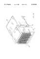
- FIGS. 1A and 1Bare perspective views of an exemplary connector in accordance with the present invention with the parts unmated and mated, respectively;
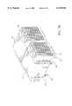
- FIG. 2is a perspective view of an exemplary pin arrangement in a header housing in accordance with the present invention
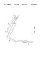
- FIG. 3is a perspective view of an exemplary ground pin in accordance with the present invention.
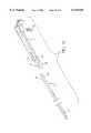
- FIG. 4is a perspective view of an exemplary signal pin in accordance with the present invention.
- FIG. 5Ais a perspective view of a rows of contacts inserted into a housing in accordance with the present invention.
- FIG. 5Bis a perspective view of the contacts of FIG. 5A inserted into a further housing in accordance with the present invention
- FIGS. 6A and 6Bare perspective views of an exemplary signal receptacle contact in accordance with the present invention.
- FIGS. 7A, 7B, and 7Care perspective views of an exemplary ground receptacle contact in accordance with the present invention.
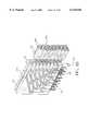
- FIG. 8Ais a perspective view of a pair of rows of exemplary signal receptacle contacts in accordance with the present invention.
- FIG. 8Bis a perspective view of the rows of contacts of FIG. 8A with an overmold and an additional housing over the contacts in accordance with the present invention
- FIG. 9Ais a perspective view of the rows of contacts of FIG. 8B with a pair of rows of exemplary ground receptacle contacts in accordance with the present invention.
- FIG. 9Bis a detailed view of the of rows of contacts of FIG. 9A;
- FIG. 9Cis a perspective view of additional rows of contacts of FIG. 9A in accordance with the present invention.
- FIG. 9Dis a perspective view of pairs of rows of exemplary ground contacts with an associated exemplary ground pin in accordance with the present invention.
- FIGS. 9E and 9Fare perspective views of a pair of exemplary socket connectors, each comprising a signal receptacle contact and a ground receptacle contact with associated pins in accordance with the present invention.
- FIG. 10shows a differential pair arrangement force diagram in accordance with the present invention.
- the present inventionis directed to an electrical connector module having a compact profile that provides a coaxial-like electrical isolation of signal connections.
- the present inventionprovides signal isolation integrity within a contact engagement region in a minimized size profile by isolating contacts in the horizontal and vertical planes.
- FIG. 1Ais a perspective view of a first embodiment of a high speed transmission connector, with the header and receptacle components separated, according to the present invention.
- FIG. 1Bis a perspective view of the connector of FIG. 1A with the header and receptacle assembled.
- a straight type of header connector 10is comprised of a header housing 12 and pins (male contacts) 15 for a signal transmission line and pins (male contacts) 17 for a ground line. These pins 15 and 17, described below with respect to FIGS. 3 and 4, are arranged on the header housing 12 of the associated connector 10 to correspond to the arrangement of ground and receptacle contacts on the receptacle 50.
- the receptacle 50preferably comprises socket housings 150, 160 that make up a receptacle housing 52.
- Each housingis preferably molded, using a plastic material such as a high temperature thermoplastic.
- the pins 15, 17are preferably stamped and formed with the preferred material being phosphor bronze or beryllium copper.
- the header 10could include suitable shielding.
- the header connector 10can be mounted on or connected to a first circuit substrate, such as a motherboard.
- FIG. 2is a perspective view of an exemplary pin arrangement in a header housing 12 in accordance with the present invention.
- the terminal portions 202 of the signal pins and ground pinsextend away from the receptacle connector to engage with a circuit substrate such as a midplane or a backplane.
- the mating portions 204 of the signal pins and ground pinsextend from the housing 12 toward, and ultimately into, the receptacle connector 50.
- a more detailed description of the header assemblyis not necessary for an understanding of the present invention.
- FIG. 3is a perspective view of a portion of an exemplary ground pin in accordance with the invention.
- the ground pin 17preferably comprises a mating beam 18 having coined mating surfaces 18a, 18b. Adjacent faces 18a, 18b (18a is the bottom face) of the mating beam 18 contact a ground receptacle contact (at contact points 70 and 72 as shown in FIG. 7A).
- the mating beam 18extends from the base of the header connector (element 10 in FIG. 1).
- the ground pin 17also has a tail section (see FIG. 1B) that extends out of the header housing opposite the receptacle housing, into, for example, a printed circuit board.
- FIG. 4is a perspective view of an exemplary signal pin in accordance with the present invention.
- the signal pin 15is also provided on the base of the header connector. As with pins 17, pins 15 have adjacent mating surfaces 22, 24.
- Header 10mates with receptacle connector 50.
- Connector 50can mount to a second circuit substrate, such as a daughterboard. Header 10 and receptacle 50 interconnect the motherboard and the daughterboard.
- Receptacle 50is a modular connector, formed by a series of modules 101 arranged side-by-side.
- a lead-in housing 150 and a second housing 160engage the modules 101, and each other, to form receptacle 50.
- FIG. 5Ais a perspective view of the rows of modules inserted into a receptacle housing 150 by the engagement of corresponding features (such as a projection and slot).
- FIG. 5Bis a perspective view of two receptacles 50 placed side-by-side. Each receptacle 50 can have a front housing 150 and a rear housing 160.
- the socket receptacle housings 150, 160are preferably comprised of plastic.
- Housing 150has a front face 151 and sidewalls 153 extending from the edges of front face 151. Front face 151 and walls 153 form an open interior in which the front portions of modules 101 reside. A surface of one wall 153 facing the open interior can include grooves (not shown) that receives spines 111 on modules 101 for alignment.
- Front face 151has an array of lead-in apertures 155, 157 that correspond to the arrangement of pins 15, 17 of header 10 and to the arrangement of contacts 55, 57 in modules 101.
- Housing 150can have projections 158 on walls 153 that enter alignment grooves (see FIG. 2) in header 10 during insertion. Housing 150 can also have blocks 159 on walls 153 to engage latching structure (see FIG. 1A) on housing 160.
- Housing 160is generally U-shaped, having a top wall 161 and sidewalls 163.
- the underside of top wall 161can include grooves (not shown) to receive the spines 111 of modules 101.
- Sidewalls 163have posts 165 for mounting to the daughterboard and a latch 167 for securing to housing 150. Once secured to housing 150, housing 160 retains modules 101 between the housings 150, 160 to form receptacle 50.
- Each module 101includes a front housing 100, rear housing 110, signal contacts 55, and ground contacts 57.
- FIGS. 6A and 6Bare perspective views of an exemplary signal receptacle contact in accordance with the present invention.
- contact 55has an L-shaped structure 48 that engages non-opposing surfaces, specifically adjacent surfaces 22, 24 of pin 15.
- the front end of L-shaped portion 48has a pair of arms 51 extending therefrom. Arms 51 have flared ends 45,47, providing surfaces to mate with the associated pin of the header connector. Major surfaces of arms 51 engage pins 15.
- the intermediate portion 54 of contact 55has a square sectional shape.
- the securing or rear end portion of contact 55has an angled terminal for mounting to a PCB thereof, with a terminal 53, respectively.
- FIGS. 7A, 7B, and 7Care perspective views of an exemplary ground receptacle contact in accordance with the present invention.
- the ground receptacle contact 57engages two non-opposed surfaces of ground pin 17.
- contact 57has an L-shape to receive a pin (e.g., the ground pin 17) on two adjacent (or non-opposing) mating surfaces 18a and 18b of the mating beam 18.
- Each portion of the "L" shapehas a shielding tab 80a, 80b to provide electromagnetic shielding.
- Tab 80ahas a contact point 70 that engages pin 17.
- contact point 70is located on a minor surface of tab 80a.
- Tab 80bhas a contact point 72 on a portion 81 cantilevered from the remainder of tab 80. As with tab 80a, contact point 72 resides on a minor surface of tab 80b. An intermediate portion of contact 57 has an angled portion 82. The securing or rear end portion of contact 57 has a terminal 83 for mounting to the board.
- portion 81extends beneath the remainder of tab 80b. Portion 81 is bent downwardly from the remainder of tab 80b to align contact point 72 with pin 17. Upon insertion of pin 17, portion 81 can flex laterally towards the remainder of tab 80b. Clearly FIG. 7B demonstrates that contact 57 engages non-opposing sides of pin 17.
- FIG. 8Ais a perspective view of a pair of rows of exemplary signal receptacle contacts in accordance with the present invention.
- adjacent columnsare generally mirror images of each other.
- Each of the signal receptacle contactsare substantially similar to the contact 55 described with respect to FIG. 6A.
- the terminal 53 and right angle portions 54vary in size to appropriately fit in a housing, as described below.
- FIG. 8Bis a perspective view of the rows of contacts of FIG. 7A after a housing 110 is overmolded about the intermediate portion 54 and part of the terminal portions 53 of the contacts 55.
- the housing 110is preferably molded, using a plastic material such as a high temperature thermoplastic.
- the housing 110comprises slots 120 in which ground receptacles 57 are later positioned, as shown in FIG. 9A.
- the overmold processalso creates spine 111 and alignment post 113.
- Front housing 100has openings 103 that receive signal contacts 55 from the rear and pins 15 from the front. Front housing 100 can also have a spine 105 that engages the corresponding groove in housing 150. Front housing 100 is preferably separately molded (i.e., not overmolded around contacts 55) and is used to isolate the signal contacts 55 and pins 15 from each other and from the ground contacts 57 and pins 17. Front housing 100 helps align the modules for insertion into receptacle housing 150 and protects the contacts during shipping.
- the housing 100is preferably molded, using a plastic material such as a high temperature thermoplastic. Housings can be placed over contacts 55 before, during, or after the overmold step.
- housing 110is overmolded about contacts 55 and housing 100 is placed over contacts 55, ground contacts 57 are placed over housings 100, 110. Corresponding portions of ground contacts 55 are inserted into grooves 120 in housing 110. The front portion of ground contacts 57 surrounds a corresponding portion of housing 100 since they have complementary edges. Housings 100, 110 and contacts 55, 57 combine to form a completed module, as shown in FIG. 9A. Modules, placed side-by-side and inserted into housing 150, form the receptacle connector.
- FIG. 9Bdisplays a close up of completed module 101.
- a plurality of rows and columns of the contacts of the connector modulescan be regularly arranged in a closely spaced array.
- the preferable pitchis 2 mm, and preferably a signal contact column is interposed between two adjacently located ground contact columns.
- Each signal pin 15is shielded by the ground receptacle contact 57 in its connector module, as well as the ground receptacle contacts 57 in neighboring modules. It should be noted that any number of connector modules can be arrayed.
- a plurality of pairs of rows of contacts, such as those described with respect to FIG. 9Aare positioned next to each other, as shown in FIG. 9C.
- FIG. 9Dis a perspective view of pairs of rows of exemplary ground contacts 57 of adjacent modules 101 with an associated exemplary ground pin.
- the pinis similar to the ground pin 17 described with respect to FIG. 3.
- the mating beam 18is inserted into the receptacle between two neighboring ground receptacles 57, one each from adjacent modules.
- the mating beam 18contacts the receptacles at four places: the contact points 70, 72 on each of the neighboring receptacles.
- the mating beam 18contacts each contact at location 72 on opposite sides of the mating beam 18, and each contact at location 70 on the bottom of the mating beam 18.
- FIGS. 9E and 9Fare perspective views of the arrangement of a pair of exemplary socket connector elements (with housings 100, 110 removed for clarity), each comprising a signal receptacle contact and a ground receptacle contact, with associated pins in accordance with the present invention.
- FIGS. 9E and 9Fcombine a pair of the signal receptacle contacts 55 of FIGS. 6A and 6B with a pair of the ground receptacle contacts 57 of FIGS. 7A-7C. Also shown are the pins 17 and 15 of FIGS. 3 and 4, respectively.
- the contact points 45 and 47mate on adjacent (or non-opposing) sides 22 and 24 of the signal pin 15, which preferably has a rectangular cross-section, and not on opposing sides of the signal pin 15.
- the contact points 70 and 72mate on adjacent (or non-opposing) sides 18a and 18b of the ground pin 17.
- the mating schemeprovides more room to surround the signal with a ground. This gives electrical isolation in a condensed area.
- each differential pair(e.g., differential pair 305) comprises a pair of ground receptacle contacts (e.g., contacts 57, and 572), and a pair of signal receptacle contacts (e.g., contacts 55 1 and 55 2 ).
- each ground contact 57contacts a ground pin, as described above, thereby generating a sets of forces represented by vectors FH 1 and FH 2 in the horizontal direction and FV 1 and FV 2 in the vertical direction.
- the ground contact 57 3contacts the ground pin which is also engaged by the adjacent contact 57, in a neighboring module 101.
- Contact 57 3generates a set of forces represented by vector FH 3 and FV 3 , in the horizontal and vertical directions, respectively.
- the ground contact 57 2contacts the ground pin which is also engaged by the adjacent contact 57 2 in a neighboring module 101.
- Contact 57 4generates a set of forces represented by vector FH 4 and FV 4 , in the horizontal and vertical directions, respectively.
- the forcesact on the connector module to create resultant forces represented by vectors FD 1 , FD 2 , FD 3 , and FD 4 , in resultant directions, preferably diagonal to the associated ground contacts.
- the vectors FD 1 and FD 5are in opposite, diagonal directions, and they have equal magnitude, as preferably do vectors FD 2 and FD 6 , thus offsetting each other and ultimately balancing the connector.
- the present inventionbalances forces using the ground and signal contacts in conjunction with the ground and signal pins in differential pairs. Similar vector balancing occurs in the other differential pairs of the connector.
- the present inventionallows implementation of full electrical isolation within the contact engagement zone in a more compact fashion. Moreover, the present invention maintains full isolation in the diagonal direction.
- ground pins and signal pins of the illustrated embodimentsare provided with an approximately square cross-section, the present invention is not limited thereto. The use of other shapes, such as rectangular and round, is also contemplated.
- the socket connector of the illustrated embodimentis provided with right angle portion, the present invention is not limited thereto.
- the present inventioncan be applied to a socket connector (not shown) having a straight type ground contact and a straight type signal contact, without a right angle portion.
Landscapes
- Details Of Connecting Devices For Male And Female Coupling (AREA)
- Coupling Device And Connection With Printed Circuit (AREA)
- Connector Housings Or Holding Contact Members (AREA)
- Cable Accessories (AREA)
- Multi-Conductor Connections (AREA)
Abstract
Description
Claims (17)
Priority Applications (13)
| Application Number | Priority Date | Filing Date | Title |
|---|---|---|---|
| US09/295,504US6116926A (en) | 1999-04-21 | 1999-04-21 | Connector for electrical isolation in a condensed area |
| SG200002141ASG103818A1 (en) | 1999-04-21 | 2000-04-13 | Connector for electrical isolation in a condensed area |
| DE60034904TDE60034904T2 (en) | 1999-04-21 | 2000-04-18 | Connector with electrical insulation in high density areas |
| EP06021950AEP1760842A1 (en) | 1999-04-21 | 2000-04-18 | Electrical connector system |
| AT00107977TATE363138T1 (en) | 1999-04-21 | 2000-04-18 | CONNECTOR WITH ELECTRICAL INSULATION IN HIGH DENSITY AREAS |
| EP00107977AEP1047157B1 (en) | 1999-04-21 | 2000-04-18 | Connector for electrical isolation in a condensed area |
| CA002306035ACA2306035C (en) | 1999-04-21 | 2000-04-18 | Connector for electrical isolation in a condensed area |
| EP06021951AEP1758211A3 (en) | 1999-04-21 | 2000-04-18 | Modular electrical connector |
| JP2000118234AJP2000315551A (en) | 1999-04-21 | 2000-04-19 | Connector with electric insulation in dense region |
| HU0001621AHUP0001621A3 (en) | 1999-04-21 | 2000-04-21 | Electrical connecting system, contact and electrical connector for the isolated electrical connecting |
| CN00106903.9ACN1271190A (en) | 1999-04-21 | 2000-04-21 | Connector of electric isolation in dense area |
| TW089107584ATW459428B (en) | 1999-04-21 | 2000-04-21 | Connector for electrical isolation in a condensed area |
| US09/613,382US6322379B1 (en) | 1999-04-21 | 2000-07-11 | Connector for electrical isolation in a condensed area |
Applications Claiming Priority (1)
| Application Number | Priority Date | Filing Date | Title |
|---|---|---|---|
| US09/295,504US6116926A (en) | 1999-04-21 | 1999-04-21 | Connector for electrical isolation in a condensed area |
Related Child Applications (1)
| Application Number | Title | Priority Date | Filing Date |
|---|---|---|---|
| US09/613,382ContinuationUS6322379B1 (en) | 1999-04-21 | 2000-07-11 | Connector for electrical isolation in a condensed area |
Publications (1)
| Publication Number | Publication Date |
|---|---|
| US6116926Atrue US6116926A (en) | 2000-09-12 |
Family
ID=23137992
Family Applications (2)
| Application Number | Title | Priority Date | Filing Date |
|---|---|---|---|
| US09/295,504Expired - LifetimeUS6116926A (en) | 1999-04-21 | 1999-04-21 | Connector for electrical isolation in a condensed area |
| US09/613,382Expired - LifetimeUS6322379B1 (en) | 1999-04-21 | 2000-07-11 | Connector for electrical isolation in a condensed area |
Family Applications After (1)
| Application Number | Title | Priority Date | Filing Date |
|---|---|---|---|
| US09/613,382Expired - LifetimeUS6322379B1 (en) | 1999-04-21 | 2000-07-11 | Connector for electrical isolation in a condensed area |
Country Status (10)
| Country | Link |
|---|---|
| US (2) | US6116926A (en) |
| EP (3) | EP1760842A1 (en) |
| JP (1) | JP2000315551A (en) |
| CN (1) | CN1271190A (en) |
| AT (1) | ATE363138T1 (en) |
| CA (1) | CA2306035C (en) |
| DE (1) | DE60034904T2 (en) |
| HU (1) | HUP0001621A3 (en) |
| SG (1) | SG103818A1 (en) |
| TW (1) | TW459428B (en) |
Cited By (120)
| Publication number | Priority date | Publication date | Assignee | Title |
|---|---|---|---|---|
| US6217386B1 (en)* | 1999-10-29 | 2001-04-17 | Hon Hai Precision Ind. Co., Ltd. | Connector with easily mating grounding contact |
| US6315605B1 (en) | 2000-05-09 | 2001-11-13 | Fci Americas Technology, Inc. | Printed circuit board stiffener assembly |
| US6328602B1 (en)* | 1999-06-17 | 2001-12-11 | Nec Corporation | Connector with less crosstalk |
| US6343955B2 (en)* | 2000-03-29 | 2002-02-05 | Berg Technology, Inc. | Electrical connector with grounding system |
| USD453735S1 (en) | 2000-12-28 | 2002-02-19 | Hon Hai Precision Ind. Co., Ltd. | Electrical connector |
| US6454605B1 (en)* | 1999-07-16 | 2002-09-24 | Molex Incorporated | Impedance-tuned termination assembly and connectors incorporating same |
| US6482038B2 (en)* | 2001-02-23 | 2002-11-19 | Fci Americas Technology, Inc. | Header assembly for mounting to a circuit substrate |
| US6537111B2 (en)* | 2000-05-31 | 2003-03-25 | Wabco Gmbh And Co. Ohg | Electric contact plug with deformable attributes |
| US6540559B1 (en)* | 2001-09-28 | 2003-04-01 | Tyco Electronics Corporation | Connector with staggered contact pattern |
| US6544046B1 (en) | 1999-10-19 | 2003-04-08 | Fci Americas Technology, Inc. | Electrical connector with strain relief |
| US6544072B2 (en) | 2001-06-12 | 2003-04-08 | Berg Technologies | Electrical connector with metallized polymeric housing |
| US6575789B2 (en)* | 1999-07-16 | 2003-06-10 | Maxwill P. Bassler | Impedance-tuned termination assembly and connectors incorporating same |
| US20030133276A1 (en)* | 2002-01-17 | 2003-07-17 | Dong Zhong | Arrangements to improve noise immunity of differential signals |
| US20030143894A1 (en)* | 2002-01-28 | 2003-07-31 | Kline Richard S. | Connector assembly interface for L-shaped ground shields and differential contact pairs |
| US6608762B2 (en) | 2001-06-01 | 2003-08-19 | Hyperchip Inc. | Midplane for data processing apparatus |
| US6607401B1 (en)* | 1999-01-28 | 2003-08-19 | Berg Technology, Inc. | Electrical connector mateable in a plurality of orientations |
| US6612857B2 (en)* | 2001-07-05 | 2003-09-02 | Bernard R. Tolmie | Electrical connector system and method having optical and/or cooling capability |
| US6638079B1 (en)* | 2002-05-21 | 2003-10-28 | Hon Hai Precision Ind. Co., Ltd. | Customizable electrical connector |
| US20030203665A1 (en)* | 2002-04-26 | 2003-10-30 | Koji Ohnishi | High-frequency electric connector having no ground terminals |
| US6695627B2 (en) | 2001-08-02 | 2004-02-24 | Fci Americas Technnology, Inc. | Profiled header ground pin |
| US20040062015A1 (en)* | 2002-09-26 | 2004-04-01 | Yakov Belopolsky | Surface mounted electrical components |
| US6776659B1 (en)* | 2003-06-26 | 2004-08-17 | Teradyne, Inc. | High speed, high density electrical connector |
| US6805278B1 (en) | 1999-10-19 | 2004-10-19 | Fci America Technology, Inc. | Self-centering connector with hold down |
| US20050170700A1 (en)* | 2001-11-14 | 2005-08-04 | Shuey Joseph B. | High speed electrical connector without ground contacts |
| US20050196987A1 (en)* | 2001-11-14 | 2005-09-08 | Shuey Joseph B. | High density, low noise, high speed mezzanine connector |
| US6945796B2 (en)* | 1999-07-16 | 2005-09-20 | Molex Incorporated | Impedance-tuned connector |
| US20050287849A1 (en)* | 2001-11-14 | 2005-12-29 | Fci Americas Technology, Inc. | Cross talk reduction and impedance matching for high speed electrical connectors |
| US20050287850A1 (en)* | 2001-11-14 | 2005-12-29 | Minich Steven E | Electrical connectors having differential signal pairs configured to reduce cross-talk on adjacent pairs |
| US20060019517A1 (en)* | 2001-11-14 | 2006-01-26 | Fci Americas Technology, Inc. | Impedance control in electrical connectors |
| US20060035530A1 (en)* | 2001-11-14 | 2006-02-16 | Fci Americas Technology, Inc. | High speed differential transmission structures without grounds |
| US20060068641A1 (en)* | 2003-09-26 | 2006-03-30 | Hull Gregory A | Impedance mathing interface for electrical connectors |
| US20060245137A1 (en)* | 2005-04-29 | 2006-11-02 | Fci Americas Technology, Inc. | Backplane connectors |
| US20070099507A1 (en)* | 2003-09-22 | 2007-05-03 | Koji Ohnishi | Electric connector |
| US20070155239A1 (en)* | 2004-01-09 | 2007-07-05 | Kouji Nakada | Connector |
| US20070207674A1 (en)* | 2006-03-03 | 2007-09-06 | Fci Americas Technology, Inc. | Broadside-to-edge-coupling connector system |
| US20070205774A1 (en)* | 2006-03-03 | 2007-09-06 | Fci Americas Technology, Inc.. | Electrical connectors |
| US20070207675A1 (en)* | 2006-03-03 | 2007-09-06 | Fci Americas Technology, Inc. | Edge and broadside coupled connector |
| US20070207641A1 (en)* | 2006-03-03 | 2007-09-06 | Fci Americas Technology, Inc. | High-density orthogonal connector |
| US20070207632A1 (en)* | 2006-03-03 | 2007-09-06 | Fci Americas Technology, Inc. | Midplane with offset connectors |
| US20070296066A1 (en)* | 2006-06-27 | 2007-12-27 | Joseph Blair Shuey | Electrical connector with elongated ground contacts |
| US7422444B1 (en) | 2007-02-28 | 2008-09-09 | Fci Americas Technology, Inc. | Orthogonal header |
| US7429176B2 (en) | 2001-07-31 | 2008-09-30 | Fci Americas Technology, Inc. | Modular mezzanine connector |
| US20090011664A1 (en)* | 2007-06-20 | 2009-01-08 | Molex Incorporated | Connector with bifurcated contact arms |
| US7497735B2 (en) | 2004-09-29 | 2009-03-03 | Fci Americas Technology, Inc. | High speed connectors that minimize signal skew and crosstalk |
| US7497736B2 (en) | 2006-12-19 | 2009-03-03 | Fci Americas Technology, Inc. | Shieldless, high-speed, low-cross-talk electrical connector |
| US7500871B2 (en) | 2006-08-21 | 2009-03-10 | Fci Americas Technology, Inc. | Electrical connector system with jogged contact tails |
| US7517250B2 (en) | 2003-09-26 | 2009-04-14 | Fci Americas Technology, Inc. | Impedance mating interface for electrical connectors |
| US20090311908A1 (en)* | 2008-06-11 | 2009-12-17 | Michael Warren Fogg | Electrical connector with ground contact modules |
| US7708569B2 (en) | 2006-10-30 | 2010-05-04 | Fci Americas Technology, Inc. | Broadside-coupled signal pair configurations for electrical connectors |
| US7713088B2 (en) | 2006-10-05 | 2010-05-11 | Fci | Broadside-coupled signal pair configurations for electrical connectors |
| EP2194606A1 (en)* | 2008-12-05 | 2010-06-09 | Tyco Electronics Corporation | Electrical connector system |
| US20110143592A1 (en)* | 2009-12-10 | 2011-06-16 | Schneider Electric Industries Sas | Electric connection device |
| US8137119B2 (en) | 2007-07-13 | 2012-03-20 | Fci Americas Technology Llc | Electrical connector system having a continuous ground at the mating interface thereof |
| US8267721B2 (en) | 2009-10-28 | 2012-09-18 | Fci Americas Technology Llc | Electrical connector having ground plates and ground coupling bar |
| US8540525B2 (en) | 2008-12-12 | 2013-09-24 | Molex Incorporated | Resonance modifying connector |
| US8545240B2 (en) | 2008-11-14 | 2013-10-01 | Molex Incorporated | Connector with terminals forming differential pairs |
| US8608510B2 (en) | 2009-07-24 | 2013-12-17 | Fci Americas Technology Llc | Dual impedance electrical connector |
| US8616919B2 (en) | 2009-11-13 | 2013-12-31 | Fci Americas Technology Llc | Attachment system for electrical connector |
| US8715003B2 (en) | 2009-12-30 | 2014-05-06 | Fci Americas Technology Llc | Electrical connector having impedance tuning ribs |
| US8764464B2 (en) | 2008-02-29 | 2014-07-01 | Fci Americas Technology Llc | Cross talk reduction for high speed electrical connectors |
| WO2014144541A1 (en)* | 2013-03-15 | 2014-09-18 | Amphenol Corporation | Mating interfaces for high speed high density electrical connectors |
| US20140308852A1 (en)* | 2008-01-17 | 2014-10-16 | Amphenol Corporation | Electrical connector assembly |
| US8864501B2 (en) | 2007-08-23 | 2014-10-21 | Molex Incorporated | Board mounted electrical connector |
| USD718253S1 (en) | 2012-04-13 | 2014-11-25 | Fci Americas Technology Llc | Electrical cable connector |
| US8905651B2 (en) | 2012-01-31 | 2014-12-09 | Fci | Dismountable optical coupling device |
| USD720698S1 (en) | 2013-03-15 | 2015-01-06 | Fci Americas Technology Llc | Electrical cable connector |
| US8944831B2 (en) | 2012-04-13 | 2015-02-03 | Fci Americas Technology Llc | Electrical connector having ribbed ground plate with engagement members |
| USD727268S1 (en) | 2012-04-13 | 2015-04-21 | Fci Americas Technology Llc | Vertical electrical connector |
| USD727852S1 (en) | 2012-04-13 | 2015-04-28 | Fci Americas Technology Llc | Ground shield for a right angle electrical connector |
| US9048583B2 (en) | 2009-03-19 | 2015-06-02 | Fci Americas Technology Llc | Electrical connector having ribbed ground plate |
| USD733662S1 (en) | 2013-01-25 | 2015-07-07 | Fci Americas Technology Llc | Connector housing for electrical connector |
| US9136634B2 (en) | 2010-09-03 | 2015-09-15 | Fci Americas Technology Llc | Low-cross-talk electrical connector |
| USD746236S1 (en) | 2012-07-11 | 2015-12-29 | Fci Americas Technology Llc | Electrical connector housing |
| US9240638B2 (en) | 2011-03-17 | 2016-01-19 | Molex, Llc | Mezzanine connector with terminal brick |
| US9246293B2 (en) | 2013-10-31 | 2016-01-26 | Tyco Electronics Corporation | Leadframe for a contact module and method of manufacturing the same |
| US9257778B2 (en) | 2012-04-13 | 2016-02-09 | Fci Americas Technology | High speed electrical connector |
| US20160056556A1 (en)* | 2013-03-28 | 2016-02-25 | Japan Aviation Electronics Industry, Ltd. | Connector assembly |
| US9277649B2 (en) | 2009-02-26 | 2016-03-01 | Fci Americas Technology Llc | Cross talk reduction for high-speed electrical connectors |
| US20160087373A1 (en)* | 2014-09-19 | 2016-03-24 | Ppc Broadband, Inc. | Buffering apparatus for messengered cables |
| US20160211618A1 (en)* | 2004-09-30 | 2016-07-21 | Amphenol Corporation | High speed, high density electrical connector |
| US9450344B2 (en) | 2014-01-22 | 2016-09-20 | Amphenol Corporation | High speed, high density electrical connector with shielded signal paths |
| US9543703B2 (en) | 2012-07-11 | 2017-01-10 | Fci Americas Technology Llc | Electrical connector with reduced stack height |
| US9685736B2 (en) | 2014-11-12 | 2017-06-20 | Amphenol Corporation | Very high speed, high density electrical interconnection system with impedance control in mating region |
| US9780493B2 (en) | 2009-09-09 | 2017-10-03 | Amphenol Corporation | Mating contacts for high speed electrical connectors |
| US9825412B2 (en)* | 2014-04-07 | 2017-11-21 | Harting Electric Gmbh & Co. Kg | Protective plate for a plug connector system |
| EP3255734A1 (en)* | 2016-06-08 | 2017-12-13 | Oupiin Electronic (Kunshan) Co., Ltd | High speed connector assembly, receptacle connector and receptacle terminal |
| US9917406B1 (en)* | 2017-01-27 | 2018-03-13 | Te Connectivity Corporation | Shielding structure for a contact module having a ground clip |
| US10141676B2 (en) | 2015-07-23 | 2018-11-27 | Amphenol Corporation | Extender module for modular connector |
| US10305224B2 (en) | 2016-05-18 | 2019-05-28 | Amphenol Corporation | Controlled impedance edged coupled connectors |
| US20190319378A1 (en)* | 2018-04-12 | 2019-10-17 | Panduit Corp. | Double Wiping Blade Contact |
| EP3641073A1 (en)* | 2013-09-25 | 2020-04-22 | Virginia Panel Corporation | High speed data module for high life cycle interconnect device |
| US10720735B2 (en) | 2016-10-19 | 2020-07-21 | Amphenol Corporation | Compliant shield for very high speed, high density electrical interconnection |
| US10931062B2 (en) | 2018-11-21 | 2021-02-23 | Amphenol Corporation | High-frequency electrical connector |
| US11031731B2 (en) | 2014-09-19 | 2021-06-08 | Ppc Broadband, Inc. | Breakaway connectors for coaxial cables |
| US11070006B2 (en) | 2017-08-03 | 2021-07-20 | Amphenol Corporation | Connector for low loss interconnection system |
| US11101611B2 (en) | 2019-01-25 | 2021-08-24 | Fci Usa Llc | I/O connector configured for cabled connection to the midboard |
| US11189943B2 (en) | 2019-01-25 | 2021-11-30 | Fci Usa Llc | I/O connector configured for cable connection to a midboard |
| US11205877B2 (en) | 2018-04-02 | 2021-12-21 | Ardent Concepts, Inc. | Controlled-impedance compliant cable termination |
| US11437762B2 (en) | 2019-02-22 | 2022-09-06 | Amphenol Corporation | High performance cable connector assembly |
| US11444397B2 (en) | 2015-07-07 | 2022-09-13 | Amphenol Fci Asia Pte. Ltd. | Electrical connector with cavity between terminals |
| US11444398B2 (en) | 2018-03-22 | 2022-09-13 | Amphenol Corporation | High density electrical connector |
| US11469554B2 (en) | 2020-01-27 | 2022-10-11 | Fci Usa Llc | High speed, high density direct mate orthogonal connector |
| US11476623B2 (en)* | 2020-11-05 | 2022-10-18 | Leviton Manufacturing Co., Inc. | Staggered contact |
| US11522310B2 (en) | 2012-08-22 | 2022-12-06 | Amphenol Corporation | High-frequency electrical connector |
| US11539171B2 (en) | 2016-08-23 | 2022-12-27 | Amphenol Corporation | Connector configurable for high performance |
| US11670879B2 (en) | 2020-01-28 | 2023-06-06 | Fci Usa Llc | High frequency midboard connector |
| US11735852B2 (en) | 2019-09-19 | 2023-08-22 | Amphenol Corporation | High speed electronic system with midboard cable connector |
| US11742601B2 (en) | 2019-05-20 | 2023-08-29 | Amphenol Corporation | High density, high speed electrical connector |
| US11757215B2 (en) | 2018-09-26 | 2023-09-12 | Amphenol East Asia Electronic Technology (Shenzhen) Co., Ltd. | High speed electrical connector and printed circuit board thereof |
| US11757224B2 (en) | 2010-05-07 | 2023-09-12 | Amphenol Corporation | High performance cable connector |
| USD1002553S1 (en) | 2021-11-03 | 2023-10-24 | Amphenol Corporation | Gasket for connector |
| US11799246B2 (en) | 2020-01-27 | 2023-10-24 | Fci Usa Llc | High speed connector |
| US11817655B2 (en) | 2020-09-25 | 2023-11-14 | Amphenol Commercial Products (Chengdu) Co., Ltd. | Compact, high speed electrical connector |
| US11831106B2 (en) | 2016-05-31 | 2023-11-28 | Amphenol Corporation | High performance cable termination |
| US11942716B2 (en) | 2020-09-22 | 2024-03-26 | Amphenol Commercial Products (Chengdu) Co., Ltd. | High speed electrical connector |
| US20240250480A1 (en)* | 2023-01-19 | 2024-07-25 | Te Connectivity Solutions Gmbh | Shielding structure for a card edge connector |
| USD1067191S1 (en) | 2021-12-14 | 2025-03-18 | Amphenol Corporation | Electrical connector |
| USD1068685S1 (en) | 2021-12-14 | 2025-04-01 | Amphenol Corporation | Electrical connector |
| US12300936B2 (en) | 2019-02-19 | 2025-05-13 | Amphenol Corporation | High speed connector |
| US12300920B2 (en) | 2021-08-13 | 2025-05-13 | Amphenol Commercial Products (Chengdu) Co., Ltd. | High performance card edge connector for high bandwidth transmission |
Families Citing this family (31)
| Publication number | Priority date | Publication date | Assignee | Title |
|---|---|---|---|---|
| US6409543B1 (en)* | 2001-01-25 | 2002-06-25 | Teradyne, Inc. | Connector molding method and shielded waferized connector made therefrom |
| NL1018176C2 (en)* | 2001-05-30 | 2002-12-03 | Fci Mechelen N V | Rectangular connector. |
| US6979215B2 (en)* | 2001-11-28 | 2005-12-27 | Molex Incorporated | High-density connector assembly with flexural capabilities |
| US6739918B2 (en)* | 2002-02-01 | 2004-05-25 | Teradyne, Inc. | Self-aligning electrical connector |
| US6905367B2 (en) | 2002-07-16 | 2005-06-14 | Silicon Bandwidth, Inc. | Modular coaxial electrical interconnect system having a modular frame and electrically shielded signal paths and a method of making the same |
| CN100524954C (en)* | 2002-12-04 | 2009-08-05 | 莫莱克斯公司 | High density connector assembly with leakage grounding structure |
| US6780069B2 (en)* | 2002-12-12 | 2004-08-24 | 3M Innovative Properties Company | Connector assembly |
| JP3841348B2 (en)* | 2003-02-25 | 2006-11-01 | 日本航空電子工業株式会社 | Connector ground structure |
| DE10310502A1 (en)* | 2003-03-11 | 2004-09-23 | Molex Inc., Lisle | Earthed electrical connector for GHz signal frequency range, has earthing terminal provided with at least 2 mechanically coupled electrical contacts |
| US6884117B2 (en)* | 2003-08-29 | 2005-04-26 | Hon Hai Precision Ind. Co., Ltd. | Electrical connector having circuit board modules positioned between metal stiffener and a housing |
| JP4663741B2 (en)* | 2005-02-22 | 2011-04-06 | モレックス インコーポレイテド | Differential signal connector having wafer type structure |
| KR20070117695A (en)* | 2005-03-31 | 2007-12-12 | 몰렉스 인코포레이티드 | High Density Rigid Connectors with Castelation |
| JP4611362B2 (en)* | 2007-11-07 | 2011-01-12 | モレックス インコーポレイテド | Differential signal connector having wafer type structure |
| US7748997B2 (en)* | 2008-07-22 | 2010-07-06 | Tyco Electronics Corporation | Receptacle for electrical connectors |
| US7637777B1 (en)* | 2008-10-13 | 2009-12-29 | Tyco Electronics Corporation | Connector assembly having a noise-reducing contact pattern |
| US8016616B2 (en)* | 2008-12-05 | 2011-09-13 | Tyco Electronics Corporation | Electrical connector system |
| US8267724B2 (en) | 2009-11-02 | 2012-09-18 | Fci Americas Technology Llc | Electrical connector having offset mounting terminals |
| TWI519011B (en)* | 2009-12-29 | 2016-01-21 | 太谷電子公司 | Electrical connector system |
| TWI580122B (en)* | 2010-02-26 | 2017-04-21 | 太谷電子公司 | Electrical connector system |
| TWI404957B (en)* | 2010-11-16 | 2013-08-11 | Univ Lunghwa Sci & Technology | ?modulated breadboard with electromagnetic interference prevention function |
| KR20140034751A (en)* | 2011-01-05 | 2014-03-20 | 톰슨 라이센싱 | Electronic device with pcbs interconnected by a flex circuit with controlled impedance |
| CN102891405B (en)* | 2011-07-21 | 2014-12-24 | 康而富控股股份有限公司 | Anti-electromagnetic-interference electric connector and terminal assembly thereof |
| JP5904573B2 (en)* | 2011-08-19 | 2016-04-13 | 富士通コンポーネント株式会社 | connector |
| TWI726014B (en)* | 2015-12-07 | 2021-05-01 | 新加坡商安姆芬諾爾富加宜(亞洲)私人有限公司 | Electrical connector, electrical cable assembly, electrically conductive ground shield for an electrical connector and method of shifting resonance frequency of the electrical connector |
| CN105742922A (en)* | 2016-03-02 | 2016-07-06 | 宁德时代新能源科技股份有限公司 | Press-fit connection structure |
| CN105932487B (en)* | 2016-04-28 | 2018-04-03 | 上海航天科工电器研究院有限公司 | A kind of electric connector of light in inserting/pulling force high-speed transfer |
| US11088480B2 (en) | 2017-06-13 | 2021-08-10 | Molex, Llc | High density receptacle |
| CN112652906B (en) | 2020-06-19 | 2022-12-02 | 东莞立讯技术有限公司 | Plugging module and cable connector |
| TWI792271B (en) | 2020-06-19 | 2023-02-11 | 大陸商東莞立訊技術有限公司 | Backplane connector assembly |
| CN212849124U (en) | 2020-06-19 | 2021-03-30 | 东莞立讯技术有限公司 | Back panel connector |
| CN112736524B (en) | 2020-12-28 | 2022-09-09 | 东莞立讯技术有限公司 | Terminal module and backplane connector |
Citations (36)
| Publication number | Priority date | Publication date | Assignee | Title |
|---|---|---|---|---|
| US32691A (en)* | 1861-07-02 | Stove | ||
| US3871728A (en)* | 1973-11-30 | 1975-03-18 | Itt | Matched impedance printed circuit board connector |
| US4686607A (en)* | 1986-01-08 | 1987-08-11 | Teradyne, Inc. | Daughter board/backplane assembly |
| USRE32691E (en) | 1982-08-23 | 1988-06-07 | Amp Incorporated | High speed modular connector for printed circuit boards |
| US4846727A (en)* | 1988-04-11 | 1989-07-11 | Amp Incorporated | Reference conductor for improving signal integrity in electrical connectors |
| US4898546A (en)* | 1988-12-16 | 1990-02-06 | E. I. Du Pont De Nemours And Company | Ground plane shield device for right angle connectors |
| US4914062A (en)* | 1989-02-15 | 1990-04-03 | W. L. Gore & Associates, Inc. | Shielded right angled header |
| US4973273A (en)* | 1989-09-22 | 1990-11-27 | Robinson Nugent, Inc. | Dual-beam receptacle socket contact |
| US4975084A (en)* | 1988-10-17 | 1990-12-04 | Amp Incorporated | Electrical connector system |
| US5055069A (en)* | 1990-06-08 | 1991-10-08 | E. I. Du Pont De Nemours And Company | Connectors with ground structure |
| US5080613A (en)* | 1989-09-20 | 1992-01-14 | Fujitsu Limited | Separable multicontact electric connector |
| US5104341A (en)* | 1989-12-20 | 1992-04-14 | Amp Incorporated | Shielded backplane connector |
| US5133679A (en)* | 1990-06-08 | 1992-07-28 | E. I. Du Pont De Nemours And Company | Connectors with ground structure |
| US5135405A (en)* | 1990-06-08 | 1992-08-04 | E. I. Du Pont De Nemours And Company | Connectors with ground structure |
| US5141453A (en)* | 1990-06-08 | 1992-08-25 | E. I. Du Pont De Nemours And Company | Connectors with ground structure |
| US5151036A (en)* | 1990-06-08 | 1992-09-29 | E. I. Du Pont De Nemours And Company | Connectors with ground structure |
| US5174770A (en)* | 1990-11-15 | 1992-12-29 | Amp Incorporated | Multicontact connector for signal transmission |
| US5197893A (en)* | 1990-03-14 | 1993-03-30 | Burndy Corporation | Connector assembly for printed circuit boards |
| US5238414A (en)* | 1991-07-24 | 1993-08-24 | Hirose Electric Co., Ltd. | High-speed transmission electrical connector |
| US5292256A (en)* | 1992-05-05 | 1994-03-08 | Molex Incorporated | High speed guarded cavity backplane connector |
| US5310354A (en)* | 1992-03-20 | 1994-05-10 | E. I. Du Pont De Nemours And Company | Integral ground terminal and tail shield |
| US5370549A (en)* | 1993-10-15 | 1994-12-06 | Lee; Chih-Chung | Slidably engaging and disengaging PGA connector integrated with simplified manipulating member |
| US5403206A (en)* | 1993-04-05 | 1995-04-04 | Teradyne, Inc. | Shielded electrical connector |
| US5421735A (en)* | 1993-01-21 | 1995-06-06 | Molex Incorporated | Modular coaxial cable connector |
| US5507655A (en)* | 1993-04-27 | 1996-04-16 | Goerlich; Rudolf | Shielded electrical connector plug |
| US5547385A (en)* | 1994-05-27 | 1996-08-20 | The Whitaker Corporation | Blind mating guides on backwards compatible connector |
| US5588851A (en)* | 1994-03-03 | 1996-12-31 | Framatome Connectors International | Connector for a cable for high frequency signals |
| US5620340A (en)* | 1992-12-31 | 1997-04-15 | Berg Technology, Inc. | Connector with improved shielding |
| US5660551A (en)* | 1993-10-20 | 1997-08-26 | Minnesota Mining And Manufacturing Company | High speed transmission line connector |
| US5664968A (en)* | 1996-03-29 | 1997-09-09 | The Whitaker Corporation | Connector assembly with shielded modules |
| US5672084A (en)* | 1995-03-29 | 1997-09-30 | Elco Corporation | High density connector receptacle |
| US5716237A (en)* | 1996-06-21 | 1998-02-10 | Lucent Technologies Inc. | Electrical connector with crosstalk compensation |
| US5775947A (en)* | 1993-07-27 | 1998-07-07 | Japan Aviation Electronics Industry, Limited | Multi-contact connector with cross-talk blocking elements between signal contacts |
| US5795191A (en)* | 1996-09-11 | 1998-08-18 | Preputnick; George | Connector assembly with shielded modules and method of making same |
| US5842872A (en)* | 1995-06-30 | 1998-12-01 | The Whitaker Corporation | Modular right angle board mountable coaxial connector |
| US5911603A (en)* | 1996-07-22 | 1999-06-15 | The Whitaker Corporation | Single piece electrical receptacle terminal for mating with a pin contact |
Family Cites Families (11)
| Publication number | Priority date | Publication date | Assignee | Title |
|---|---|---|---|---|
| US4571014A (en)* | 1984-05-02 | 1986-02-18 | At&T Bell Laboratories | High frequency modular connector |
| US5358413A (en)* | 1992-12-08 | 1994-10-25 | The Whitaker Corporation | Right-angle board-mountable electrical connector with precision terminal positioning |
| US5304069A (en)* | 1993-07-22 | 1994-04-19 | Molex Incorporated | Grounding electrical connectors |
| DE4400702C2 (en)* | 1994-01-12 | 2000-08-10 | Grote & Hartmann | One-piece connector device |
| US5967844A (en)* | 1995-04-04 | 1999-10-19 | Berg Technology, Inc. | Electrically enhanced modular connector for printed wiring board |
| US5842887A (en)* | 1995-06-20 | 1998-12-01 | Berg Technology, Inc. | Connector with improved shielding |
| JP3099111B2 (en)* | 1996-05-31 | 2000-10-16 | モレックス インコーポレーテッド | Receptacle contact, receptacle contact strip, and method of manufacturing receptacle contact |
| DE69721070T2 (en)* | 1996-06-14 | 2004-01-29 | Framatome Connectors Int | LOCKED AND SHIELDED ELECTRICAL CONNECTORS |
| US6083047A (en)* | 1997-01-16 | 2000-07-04 | Berg Technology, Inc. | Modular electrical PCB assembly connector |
| US6227882B1 (en)* | 1997-10-01 | 2001-05-08 | Berg Technology, Inc. | Connector for electrical isolation in a condensed area |
| US6132255A (en)* | 1999-01-08 | 2000-10-17 | Berg Technology, Inc. | Connector with improved shielding and insulation |
- 1999
- 1999-04-21USUS09/295,504patent/US6116926A/ennot_activeExpired - Lifetime
- 2000
- 2000-04-13SGSG200002141Apatent/SG103818A1/enunknown
- 2000-04-18ATAT00107977Tpatent/ATE363138T1/ennot_activeIP Right Cessation
- 2000-04-18EPEP06021950Apatent/EP1760842A1/ennot_activeWithdrawn
- 2000-04-18CACA002306035Apatent/CA2306035C/ennot_activeExpired - Fee Related
- 2000-04-18EPEP06021951Apatent/EP1758211A3/ennot_activeWithdrawn
- 2000-04-18DEDE60034904Tpatent/DE60034904T2/ennot_activeExpired - Fee Related
- 2000-04-18EPEP00107977Apatent/EP1047157B1/ennot_activeExpired - Lifetime
- 2000-04-19JPJP2000118234Apatent/JP2000315551A/enactivePending
- 2000-04-21TWTW089107584Apatent/TW459428B/ennot_activeIP Right Cessation
- 2000-04-21CNCN00106903.9Apatent/CN1271190A/enactivePending
- 2000-04-21HUHU0001621Apatent/HUP0001621A3/enunknown
- 2000-07-11USUS09/613,382patent/US6322379B1/ennot_activeExpired - Lifetime
Patent Citations (39)
| Publication number | Priority date | Publication date | Assignee | Title |
|---|---|---|---|---|
| US32691A (en)* | 1861-07-02 | Stove | ||
| US3871728A (en)* | 1973-11-30 | 1975-03-18 | Itt | Matched impedance printed circuit board connector |
| USRE32691E (en) | 1982-08-23 | 1988-06-07 | Amp Incorporated | High speed modular connector for printed circuit boards |
| US4686607A (en)* | 1986-01-08 | 1987-08-11 | Teradyne, Inc. | Daughter board/backplane assembly |
| US4846727A (en)* | 1988-04-11 | 1989-07-11 | Amp Incorporated | Reference conductor for improving signal integrity in electrical connectors |
| US4975084A (en)* | 1988-10-17 | 1990-12-04 | Amp Incorporated | Electrical connector system |
| US4898546A (en)* | 1988-12-16 | 1990-02-06 | E. I. Du Pont De Nemours And Company | Ground plane shield device for right angle connectors |
| US4914062A (en)* | 1989-02-15 | 1990-04-03 | W. L. Gore & Associates, Inc. | Shielded right angled header |
| US5080613A (en)* | 1989-09-20 | 1992-01-14 | Fujitsu Limited | Separable multicontact electric connector |
| US4973273A (en)* | 1989-09-22 | 1990-11-27 | Robinson Nugent, Inc. | Dual-beam receptacle socket contact |
| US5104341A (en)* | 1989-12-20 | 1992-04-14 | Amp Incorporated | Shielded backplane connector |
| US5197893A (en)* | 1990-03-14 | 1993-03-30 | Burndy Corporation | Connector assembly for printed circuit boards |
| US5055069A (en)* | 1990-06-08 | 1991-10-08 | E. I. Du Pont De Nemours And Company | Connectors with ground structure |
| US5133679A (en)* | 1990-06-08 | 1992-07-28 | E. I. Du Pont De Nemours And Company | Connectors with ground structure |
| US5135405A (en)* | 1990-06-08 | 1992-08-04 | E. I. Du Pont De Nemours And Company | Connectors with ground structure |
| US5141453A (en)* | 1990-06-08 | 1992-08-25 | E. I. Du Pont De Nemours And Company | Connectors with ground structure |
| US5151036A (en)* | 1990-06-08 | 1992-09-29 | E. I. Du Pont De Nemours And Company | Connectors with ground structure |
| US5174770A (en)* | 1990-11-15 | 1992-12-29 | Amp Incorporated | Multicontact connector for signal transmission |
| US5238414A (en)* | 1991-07-24 | 1993-08-24 | Hirose Electric Co., Ltd. | High-speed transmission electrical connector |
| US5310354A (en)* | 1992-03-20 | 1994-05-10 | E. I. Du Pont De Nemours And Company | Integral ground terminal and tail shield |
| US5292256A (en)* | 1992-05-05 | 1994-03-08 | Molex Incorporated | High speed guarded cavity backplane connector |
| US5620340A (en)* | 1992-12-31 | 1997-04-15 | Berg Technology, Inc. | Connector with improved shielding |
| US5421735A (en)* | 1993-01-21 | 1995-06-06 | Molex Incorporated | Modular coaxial cable connector |
| US5607326A (en)* | 1993-04-05 | 1997-03-04 | Teradyne, Inc. | Shielded electrical connector |
| US5484310A (en)* | 1993-04-05 | 1996-01-16 | Teradyne, Inc. | Shielded electrical connector |
| US5605476A (en)* | 1993-04-05 | 1997-02-25 | Teradyne, Inc. | Shielded electrical connector |
| US5403206A (en)* | 1993-04-05 | 1995-04-04 | Teradyne, Inc. | Shielded electrical connector |
| US5507655A (en)* | 1993-04-27 | 1996-04-16 | Goerlich; Rudolf | Shielded electrical connector plug |
| US5775947A (en)* | 1993-07-27 | 1998-07-07 | Japan Aviation Electronics Industry, Limited | Multi-contact connector with cross-talk blocking elements between signal contacts |
| US5370549A (en)* | 1993-10-15 | 1994-12-06 | Lee; Chih-Chung | Slidably engaging and disengaging PGA connector integrated with simplified manipulating member |
| US5660551A (en)* | 1993-10-20 | 1997-08-26 | Minnesota Mining And Manufacturing Company | High speed transmission line connector |
| US5588851A (en)* | 1994-03-03 | 1996-12-31 | Framatome Connectors International | Connector for a cable for high frequency signals |
| US5547385A (en)* | 1994-05-27 | 1996-08-20 | The Whitaker Corporation | Blind mating guides on backwards compatible connector |
| US5672084A (en)* | 1995-03-29 | 1997-09-30 | Elco Corporation | High density connector receptacle |
| US5842872A (en)* | 1995-06-30 | 1998-12-01 | The Whitaker Corporation | Modular right angle board mountable coaxial connector |
| US5664968A (en)* | 1996-03-29 | 1997-09-09 | The Whitaker Corporation | Connector assembly with shielded modules |
| US5716237A (en)* | 1996-06-21 | 1998-02-10 | Lucent Technologies Inc. | Electrical connector with crosstalk compensation |
| US5911603A (en)* | 1996-07-22 | 1999-06-15 | The Whitaker Corporation | Single piece electrical receptacle terminal for mating with a pin contact |
| US5795191A (en)* | 1996-09-11 | 1998-08-18 | Preputnick; George | Connector assembly with shielded modules and method of making same |
Cited By (229)
| Publication number | Priority date | Publication date | Assignee | Title |
|---|---|---|---|---|
| US6607401B1 (en)* | 1999-01-28 | 2003-08-19 | Berg Technology, Inc. | Electrical connector mateable in a plurality of orientations |
| US6328602B1 (en)* | 1999-06-17 | 2001-12-11 | Nec Corporation | Connector with less crosstalk |
| US6945796B2 (en)* | 1999-07-16 | 2005-09-20 | Molex Incorporated | Impedance-tuned connector |
| US20050260872A1 (en)* | 1999-07-16 | 2005-11-24 | Bassler Maxwill P | Impedance-tuned connector |
| US7165981B2 (en) | 1999-07-16 | 2007-01-23 | Molex Incorporated | Impedance-tuned connector |
| US6454605B1 (en)* | 1999-07-16 | 2002-09-24 | Molex Incorporated | Impedance-tuned termination assembly and connectors incorporating same |
| US6575789B2 (en)* | 1999-07-16 | 2003-06-10 | Maxwill P. Bassler | Impedance-tuned termination assembly and connectors incorporating same |
| US6544046B1 (en) | 1999-10-19 | 2003-04-08 | Fci Americas Technology, Inc. | Electrical connector with strain relief |
| US6805278B1 (en) | 1999-10-19 | 2004-10-19 | Fci America Technology, Inc. | Self-centering connector with hold down |
| US6217386B1 (en)* | 1999-10-29 | 2001-04-17 | Hon Hai Precision Ind. Co., Ltd. | Connector with easily mating grounding contact |
| US6364710B1 (en)* | 2000-03-29 | 2002-04-02 | Berg Technology, Inc. | Electrical connector with grounding system |
| US6343955B2 (en)* | 2000-03-29 | 2002-02-05 | Berg Technology, Inc. | Electrical connector with grounding system |
| US6315605B1 (en) | 2000-05-09 | 2001-11-13 | Fci Americas Technology, Inc. | Printed circuit board stiffener assembly |
| US6537111B2 (en)* | 2000-05-31 | 2003-03-25 | Wabco Gmbh And Co. Ohg | Electric contact plug with deformable attributes |
| USD453735S1 (en) | 2000-12-28 | 2002-02-19 | Hon Hai Precision Ind. Co., Ltd. | Electrical connector |
| EP1237229A3 (en)* | 2001-02-23 | 2010-01-06 | Fci | Header assembly for mounting to a circuit substrate |
| US6482038B2 (en)* | 2001-02-23 | 2002-11-19 | Fci Americas Technology, Inc. | Header assembly for mounting to a circuit substrate |
| US6608762B2 (en) | 2001-06-01 | 2003-08-19 | Hyperchip Inc. | Midplane for data processing apparatus |
| US6544072B2 (en) | 2001-06-12 | 2003-04-08 | Berg Technologies | Electrical connector with metallized polymeric housing |
| US6612857B2 (en)* | 2001-07-05 | 2003-09-02 | Bernard R. Tolmie | Electrical connector system and method having optical and/or cooling capability |
| US7429176B2 (en) | 2001-07-31 | 2008-09-30 | Fci Americas Technology, Inc. | Modular mezzanine connector |
| US6695627B2 (en) | 2001-08-02 | 2004-02-24 | Fci Americas Technnology, Inc. | Profiled header ground pin |
| US6540559B1 (en)* | 2001-09-28 | 2003-04-01 | Tyco Electronics Corporation | Connector with staggered contact pattern |
| US7442054B2 (en) | 2001-11-14 | 2008-10-28 | Fci Americas Technology, Inc. | Electrical connectors having differential signal pairs configured to reduce cross-talk on adjacent pairs |
| US20070059952A1 (en)* | 2001-11-14 | 2007-03-15 | Fci Americas Technology, Inc. | Impedance control in electrical connectors |
| US7467955B2 (en) | 2001-11-14 | 2008-12-23 | Fci Americas Technology, Inc. | Impedance control in electrical connectors |
| US20080214029A1 (en)* | 2001-11-14 | 2008-09-04 | Lemke Timothy A | Shieldless, High-Speed Electrical Connectors |
| US7390200B2 (en) | 2001-11-14 | 2008-06-24 | Fci Americas Technology, Inc. | High speed differential transmission structures without grounds |
| US7390218B2 (en) | 2001-11-14 | 2008-06-24 | Fci Americas Technology, Inc. | Shieldless, high-speed electrical connectors |
| US20050170700A1 (en)* | 2001-11-14 | 2005-08-04 | Shuey Joseph B. | High speed electrical connector without ground contacts |
| US20050196987A1 (en)* | 2001-11-14 | 2005-09-08 | Shuey Joseph B. | High density, low noise, high speed mezzanine connector |
| US7331800B2 (en) | 2001-11-14 | 2008-02-19 | Fci Americas Technology, Inc. | Shieldless, high-speed electrical connectors |
| US7309239B2 (en) | 2001-11-14 | 2007-12-18 | Fci Americas Technology, Inc. | High-density, low-noise, high-speed mezzanine connector |
| US20050287849A1 (en)* | 2001-11-14 | 2005-12-29 | Fci Americas Technology, Inc. | Cross talk reduction and impedance matching for high speed electrical connectors |
| US20050287850A1 (en)* | 2001-11-14 | 2005-12-29 | Minich Steven E | Electrical connectors having differential signal pairs configured to reduce cross-talk on adjacent pairs |
| US20060019517A1 (en)* | 2001-11-14 | 2006-01-26 | Fci Americas Technology, Inc. | Impedance control in electrical connectors |
| US20060035530A1 (en)* | 2001-11-14 | 2006-02-16 | Fci Americas Technology, Inc. | High speed differential transmission structures without grounds |
| US20060063404A1 (en)* | 2001-11-14 | 2006-03-23 | Fci Americas Technology, Inc. | Electrical connectors having contacts that may be selectively designated as either signal or ground contacts |
| US20070190825A1 (en)* | 2001-11-14 | 2007-08-16 | Fci Americas Technology, Inc. | High-density, low-noise, high-speed mezzanine connector |
| US7114964B2 (en) | 2001-11-14 | 2006-10-03 | Fci Americas Technology, Inc. | Cross talk reduction and impedance matching for high speed electrical connectors |
| US7118391B2 (en) | 2001-11-14 | 2006-10-10 | Fci Americas Technology, Inc. | Electrical connectors having contacts that may be selectively designated as either signal or ground contacts |
| US20060234532A1 (en)* | 2001-11-14 | 2006-10-19 | Fci Americas Technology, Inc. | Shieldless, high-speed electrical connectors |
| US7229318B2 (en) | 2001-11-14 | 2007-06-12 | Fci Americas Technology, Inc. | Shieldless, high-speed electrical connectors |
| US20060246756A1 (en)* | 2001-11-14 | 2006-11-02 | Fci Americas Technology, Inc. | Shieldless, high-speed electrical connectors |
| US20070099464A1 (en)* | 2001-11-14 | 2007-05-03 | Winings Clifford L | Shieldless, High-Speed Electrical Connectors |
| US7182643B2 (en) | 2001-11-14 | 2007-02-27 | Fci Americas Technology, Inc. | Shieldless, high-speed electrical connectors |
| US20080248693A1 (en)* | 2001-11-14 | 2008-10-09 | Fci Americas Technology, Inc. | Shieldless, high-speed electrical connectors |
| US20030133276A1 (en)* | 2002-01-17 | 2003-07-17 | Dong Zhong | Arrangements to improve noise immunity of differential signals |
| US6899566B2 (en)* | 2002-01-28 | 2005-05-31 | Erni Elektroapparate Gmbh | Connector assembly interface for L-shaped ground shields and differential contact pairs |
| US20030143894A1 (en)* | 2002-01-28 | 2003-07-31 | Kline Richard S. | Connector assembly interface for L-shaped ground shields and differential contact pairs |
| US20030203665A1 (en)* | 2002-04-26 | 2003-10-30 | Koji Ohnishi | High-frequency electric connector having no ground terminals |
| US6843686B2 (en)* | 2002-04-26 | 2005-01-18 | Honda Tsushin Kogyo Co., Ltd. | High-frequency electric connector having no ground terminals |
| US6638079B1 (en)* | 2002-05-21 | 2003-10-28 | Hon Hai Precision Ind. Co., Ltd. | Customizable electrical connector |
| US7535723B2 (en) | 2002-09-26 | 2009-05-19 | Fci Americas Technology, Inc. | Surface mounted electrical components and method for mounting and retaining same |
| US20040121626A1 (en)* | 2002-09-26 | 2004-06-24 | Fci Americas Technology, Inc. | Surface mounted electrical components and method for mounting and retaining same |
| US20040237298A1 (en)* | 2002-09-26 | 2004-12-02 | Fci Americas Technology, Inc | Surface mounted electrical components and method for mounting and retaining same |
| US7249411B2 (en) | 2002-09-26 | 2007-07-31 | Fci Americas Technology, Inc. | Methods for mounting surface-mounted electrical components |
| US20040062015A1 (en)* | 2002-09-26 | 2004-04-01 | Yakov Belopolsky | Surface mounted electrical components |
| US6791845B2 (en) | 2002-09-26 | 2004-09-14 | Fci Americas Technology, Inc. | Surface mounted electrical components |
| US6776659B1 (en)* | 2003-06-26 | 2004-08-17 | Teradyne, Inc. | High speed, high density electrical connector |
| US20070099507A1 (en)* | 2003-09-22 | 2007-05-03 | Koji Ohnishi | Electric connector |
| US7524209B2 (en) | 2003-09-26 | 2009-04-28 | Fci Americas Technology, Inc. | Impedance mating interface for electrical connectors |
| US7837504B2 (en) | 2003-09-26 | 2010-11-23 | Fci Americas Technology, Inc. | Impedance mating interface for electrical connectors |
| US7517250B2 (en) | 2003-09-26 | 2009-04-14 | Fci Americas Technology, Inc. | Impedance mating interface for electrical connectors |
| US20060068641A1 (en)* | 2003-09-26 | 2006-03-30 | Hull Gregory A | Impedance mathing interface for electrical connectors |
| US7381092B2 (en)* | 2004-01-09 | 2008-06-03 | Japan Aviation Electronics Industry, Limited | Connector |
| US20070155239A1 (en)* | 2004-01-09 | 2007-07-05 | Kouji Nakada | Connector |
| US7497735B2 (en) | 2004-09-29 | 2009-03-03 | Fci Americas Technology, Inc. | High speed connectors that minimize signal skew and crosstalk |
| US9899774B2 (en)* | 2004-09-30 | 2018-02-20 | Amphenol Corporation | High speed, high density electrical connector |
| US20160211618A1 (en)* | 2004-09-30 | 2016-07-21 | Amphenol Corporation | High speed, high density electrical connector |
| US20060245137A1 (en)* | 2005-04-29 | 2006-11-02 | Fci Americas Technology, Inc. | Backplane connectors |
| US7331830B2 (en) | 2006-03-03 | 2008-02-19 | Fci Americas Technology, Inc. | High-density orthogonal connector |
| US20070207632A1 (en)* | 2006-03-03 | 2007-09-06 | Fci Americas Technology, Inc. | Midplane with offset connectors |
| US7431616B2 (en) | 2006-03-03 | 2008-10-07 | Fci Americas Technology, Inc. | Orthogonal electrical connectors |
| US20070207674A1 (en)* | 2006-03-03 | 2007-09-06 | Fci Americas Technology, Inc. | Broadside-to-edge-coupling connector system |
| US20070205774A1 (en)* | 2006-03-03 | 2007-09-06 | Fci Americas Technology, Inc.. | Electrical connectors |
| US20070207675A1 (en)* | 2006-03-03 | 2007-09-06 | Fci Americas Technology, Inc. | Edge and broadside coupled connector |
| US20070207641A1 (en)* | 2006-03-03 | 2007-09-06 | Fci Americas Technology, Inc. | High-density orthogonal connector |
| US7407413B2 (en) | 2006-03-03 | 2008-08-05 | Fci Americas Technology, Inc. | Broadside-to-edge-coupling connector system |
| US7344391B2 (en) | 2006-03-03 | 2008-03-18 | Fci Americas Technology, Inc. | Edge and broadside coupled connector |
| US7462924B2 (en) | 2006-06-27 | 2008-12-09 | Fci Americas Technology, Inc. | Electrical connector with elongated ground contacts |
| US20070296066A1 (en)* | 2006-06-27 | 2007-12-27 | Joseph Blair Shuey | Electrical connector with elongated ground contacts |
| US7500871B2 (en) | 2006-08-21 | 2009-03-10 | Fci Americas Technology, Inc. | Electrical connector system with jogged contact tails |
| US7837505B2 (en) | 2006-08-21 | 2010-11-23 | Fci Americas Technology Llc | Electrical connector system with jogged contact tails |
| US7713088B2 (en) | 2006-10-05 | 2010-05-11 | Fci | Broadside-coupled signal pair configurations for electrical connectors |
| US7708569B2 (en) | 2006-10-30 | 2010-05-04 | Fci Americas Technology, Inc. | Broadside-coupled signal pair configurations for electrical connectors |
| US7762843B2 (en) | 2006-12-19 | 2010-07-27 | Fci Americas Technology, Inc. | Shieldless, high-speed, low-cross-talk electrical connector |
| US8678860B2 (en) | 2006-12-19 | 2014-03-25 | Fci Americas Technology Llc | Shieldless, high-speed, low-cross-talk electrical connector |
| US7497736B2 (en) | 2006-12-19 | 2009-03-03 | Fci Americas Technology, Inc. | Shieldless, high-speed, low-cross-talk electrical connector |
| US8382521B2 (en) | 2006-12-19 | 2013-02-26 | Fci Americas Technology Llc | Shieldless, high-speed, low-cross-talk electrical connector |
| US8096832B2 (en) | 2006-12-19 | 2012-01-17 | Fci Americas Technology Llc | Shieldless, high-speed, low-cross-talk electrical connector |
| US7422444B1 (en) | 2007-02-28 | 2008-09-09 | Fci Americas Technology, Inc. | Orthogonal header |
| US7967647B2 (en)* | 2007-02-28 | 2011-06-28 | Fci Americas Technology Llc | Orthogonal header |
| US8057267B2 (en) | 2007-02-28 | 2011-11-15 | Fci Americas Technology Llc | Orthogonal header |
| US7789708B2 (en)* | 2007-06-20 | 2010-09-07 | Molex Incorporated | Connector with bifurcated contact arms |
| US20090011664A1 (en)* | 2007-06-20 | 2009-01-08 | Molex Incorporated | Connector with bifurcated contact arms |
| US8137119B2 (en) | 2007-07-13 | 2012-03-20 | Fci Americas Technology Llc | Electrical connector system having a continuous ground at the mating interface thereof |
| US8864501B2 (en) | 2007-08-23 | 2014-10-21 | Molex Incorporated | Board mounted electrical connector |
| US20140308852A1 (en)* | 2008-01-17 | 2014-10-16 | Amphenol Corporation | Electrical connector assembly |
| US9564696B2 (en)* | 2008-01-17 | 2017-02-07 | Amphenol Corporation | Electrical connector assembly |
| US8764464B2 (en) | 2008-02-29 | 2014-07-01 | Fci Americas Technology Llc | Cross talk reduction for high speed electrical connectors |
| US7674133B2 (en)* | 2008-06-11 | 2010-03-09 | Tyco Electronics Corporation | Electrical connector with ground contact modules |
| US20090311908A1 (en)* | 2008-06-11 | 2009-12-17 | Michael Warren Fogg | Electrical connector with ground contact modules |
| US8545240B2 (en) | 2008-11-14 | 2013-10-01 | Molex Incorporated | Connector with terminals forming differential pairs |
| US20100144201A1 (en)* | 2008-12-05 | 2010-06-10 | Defibaugh George R | Electrical connector system |
| EP2194606A1 (en)* | 2008-12-05 | 2010-06-09 | Tyco Electronics Corporation | Electrical connector system |
| US7775802B2 (en) | 2008-12-05 | 2010-08-17 | Tyco Electronics Corporation | Electrical connector system |
| CN101853996B (en)* | 2008-12-05 | 2014-08-20 | 泰科电子公司 | Electrical connector system |
| US8651881B2 (en) | 2008-12-12 | 2014-02-18 | Molex Incorporated | Resonance modifying connector |
| US8992237B2 (en) | 2008-12-12 | 2015-03-31 | Molex Incorporated | Resonance modifying connector |
| US8540525B2 (en) | 2008-12-12 | 2013-09-24 | Molex Incorporated | Resonance modifying connector |
| US9277649B2 (en) | 2009-02-26 | 2016-03-01 | Fci Americas Technology Llc | Cross talk reduction for high-speed electrical connectors |
| US9048583B2 (en) | 2009-03-19 | 2015-06-02 | Fci Americas Technology Llc | Electrical connector having ribbed ground plate |
| US10096921B2 (en) | 2009-03-19 | 2018-10-09 | Fci Usa Llc | Electrical connector having ribbed ground plate |
| US9461410B2 (en) | 2009-03-19 | 2016-10-04 | Fci Americas Technology Llc | Electrical connector having ribbed ground plate |
| US10720721B2 (en) | 2009-03-19 | 2020-07-21 | Fci Usa Llc | Electrical connector having ribbed ground plate |
| US8608510B2 (en) | 2009-07-24 | 2013-12-17 | Fci Americas Technology Llc | Dual impedance electrical connector |
| US9780493B2 (en) | 2009-09-09 | 2017-10-03 | Amphenol Corporation | Mating contacts for high speed electrical connectors |
| US8267721B2 (en) | 2009-10-28 | 2012-09-18 | Fci Americas Technology Llc | Electrical connector having ground plates and ground coupling bar |
| US8616919B2 (en) | 2009-11-13 | 2013-12-31 | Fci Americas Technology Llc | Attachment system for electrical connector |
| US8403704B2 (en)* | 2009-12-10 | 2013-03-26 | Schneider Electric Industries Sas | Electronic connection device with grounding feature |
| US20110143592A1 (en)* | 2009-12-10 | 2011-06-16 | Schneider Electric Industries Sas | Electric connection device |
| US8715003B2 (en) | 2009-12-30 | 2014-05-06 | Fci Americas Technology Llc | Electrical connector having impedance tuning ribs |
| US11757224B2 (en) | 2010-05-07 | 2023-09-12 | Amphenol Corporation | High performance cable connector |
| US9136634B2 (en) | 2010-09-03 | 2015-09-15 | Fci Americas Technology Llc | Low-cross-talk electrical connector |
| US10333237B2 (en) | 2011-03-17 | 2019-06-25 | Molex, Llc | Mezzanine connector with terminal brick |
| US9240638B2 (en) | 2011-03-17 | 2016-01-19 | Molex, Llc | Mezzanine connector with terminal brick |
| US9793628B2 (en) | 2011-03-17 | 2017-10-17 | Molex, Llc | Mezzanine connector with terminal brick |
| US8905651B2 (en) | 2012-01-31 | 2014-12-09 | Fci | Dismountable optical coupling device |
| USD748063S1 (en) | 2012-04-13 | 2016-01-26 | Fci Americas Technology Llc | Electrical ground shield |
| USD718253S1 (en) | 2012-04-13 | 2014-11-25 | Fci Americas Technology Llc | Electrical cable connector |
| USD727852S1 (en) | 2012-04-13 | 2015-04-28 | Fci Americas Technology Llc | Ground shield for a right angle electrical connector |
| US9257778B2 (en) | 2012-04-13 | 2016-02-09 | Fci Americas Technology | High speed electrical connector |
| USD750025S1 (en) | 2012-04-13 | 2016-02-23 | Fci Americas Technology Llc | Vertical electrical connector |
| USD750030S1 (en) | 2012-04-13 | 2016-02-23 | Fci Americas Technology Llc | Electrical cable connector |
| USD816044S1 (en) | 2012-04-13 | 2018-04-24 | Fci Americas Technology Llc | Electrical cable connector |
| USD790471S1 (en) | 2012-04-13 | 2017-06-27 | Fci Americas Technology Llc | Vertical electrical connector |
| US8944831B2 (en) | 2012-04-13 | 2015-02-03 | Fci Americas Technology Llc | Electrical connector having ribbed ground plate with engagement members |
| USD727268S1 (en) | 2012-04-13 | 2015-04-21 | Fci Americas Technology Llc | Vertical electrical connector |
| US9831605B2 (en) | 2012-04-13 | 2017-11-28 | Fci Americas Technology Llc | High speed electrical connector |
| USD751507S1 (en) | 2012-07-11 | 2016-03-15 | Fci Americas Technology Llc | Electrical connector |
| USD746236S1 (en) | 2012-07-11 | 2015-12-29 | Fci Americas Technology Llc | Electrical connector housing |
| US9871323B2 (en) | 2012-07-11 | 2018-01-16 | Fci Americas Technology Llc | Electrical connector with reduced stack height |
| US9543703B2 (en) | 2012-07-11 | 2017-01-10 | Fci Americas Technology Llc | Electrical connector with reduced stack height |
| US11901663B2 (en) | 2012-08-22 | 2024-02-13 | Amphenol Corporation | High-frequency electrical connector |
| US11522310B2 (en) | 2012-08-22 | 2022-12-06 | Amphenol Corporation | High-frequency electrical connector |
| USD745852S1 (en) | 2013-01-25 | 2015-12-22 | Fci Americas Technology Llc | Electrical connector |
| USD766832S1 (en) | 2013-01-25 | 2016-09-20 | Fci Americas Technology Llc | Electrical connector |
| USD733662S1 (en) | 2013-01-25 | 2015-07-07 | Fci Americas Technology Llc | Connector housing for electrical connector |
| USD772168S1 (en) | 2013-01-25 | 2016-11-22 | Fci Americas Technology Llc | Connector housing for electrical connector |
| US20150118922A9 (en)* | 2013-03-15 | 2015-04-30 | Amphenol Corporation | Mating interfaces for high speed high density electrical connector |
| US9419360B2 (en)* | 2013-03-15 | 2016-08-16 | Amphenol Corporation | Mating interfaces for high speed high density electrical connectors |
| USD720698S1 (en) | 2013-03-15 | 2015-01-06 | Fci Americas Technology Llc | Electrical cable connector |
| CN105122553A (en)* | 2013-03-15 | 2015-12-02 | 安费诺有限公司 | Mating interface for high-speed, high-density electrical connectors |
| US20140287627A1 (en)* | 2013-03-15 | 2014-09-25 | Amphenol Corporation | Mating interfaces for high speed high density electrical connectors |
| US9362646B2 (en)* | 2013-03-15 | 2016-06-07 | Amphenol Corporation | Mating interfaces for high speed high density electrical connector |
| CN107623202A (en)* | 2013-03-15 | 2018-01-23 | 安费诺有限公司 | Mating interface for high-speed and high-density electrical connector |
| WO2014144541A1 (en)* | 2013-03-15 | 2014-09-18 | Amphenol Corporation | Mating interfaces for high speed high density electrical connectors |
| US9419357B2 (en)* | 2013-03-28 | 2016-08-16 | Japan Aviation Electronics Industry, Ltd. | Connector assembly |
| US20160056556A1 (en)* | 2013-03-28 | 2016-02-25 | Japan Aviation Electronics Industry, Ltd. | Connector assembly |
| EP3641073A1 (en)* | 2013-09-25 | 2020-04-22 | Virginia Panel Corporation | High speed data module for high life cycle interconnect device |
| US9246293B2 (en) | 2013-10-31 | 2016-01-26 | Tyco Electronics Corporation | Leadframe for a contact module and method of manufacturing the same |
| US9905975B2 (en) | 2014-01-22 | 2018-02-27 | Amphenol Corporation | Very high speed, high density electrical interconnection system with edge to broadside transition |
| US9774144B2 (en) | 2014-01-22 | 2017-09-26 | Amphenol Corporation | High speed, high density electrical connector with shielded signal paths |
| US9450344B2 (en) | 2014-01-22 | 2016-09-20 | Amphenol Corporation | High speed, high density electrical connector with shielded signal paths |
| US9509101B2 (en) | 2014-01-22 | 2016-11-29 | Amphenol Corporation | High speed, high density electrical connector with shielded signal paths |
| US11688980B2 (en) | 2014-01-22 | 2023-06-27 | Amphenol Corporation | Very high speed, high density electrical interconnection system with broadside subassemblies |
| US11715914B2 (en) | 2014-01-22 | 2023-08-01 | Amphenol Corporation | High speed, high density electrical connector with shielded signal paths |
| US10707626B2 (en) | 2014-01-22 | 2020-07-07 | Amphenol Corporation | Very high speed, high density electrical interconnection system with edge to broadside transition |
| US12300942B2 (en)* | 2014-01-22 | 2025-05-13 | Amphenol Corporation | Very high speed, high density electrical interconnection system with broadside subassemblies |
| US9825412B2 (en)* | 2014-04-07 | 2017-11-21 | Harting Electric Gmbh & Co. Kg | Protective plate for a plug connector system |
| US10431929B2 (en) | 2014-09-19 | 2019-10-01 | Ppc Broadband, Inc. | Buffering apparatus for messengered cables |
| US11855389B2 (en) | 2014-09-19 | 2023-12-26 | Ppc Broadband, Inc. | Breakaway connectors for coaxial cables |
| US20160087373A1 (en)* | 2014-09-19 | 2016-03-24 | Ppc Broadband, Inc. | Buffering apparatus for messengered cables |
| US9450333B2 (en)* | 2014-09-19 | 2016-09-20 | Ppc Broadband, Inc. | Buffering apparatus for messengered cables |
| US11031731B2 (en) | 2014-09-19 | 2021-06-08 | Ppc Broadband, Inc. | Breakaway connectors for coaxial cables |
| US10840649B2 (en) | 2014-11-12 | 2020-11-17 | Amphenol Corporation | Organizer for a very high speed, high density electrical interconnection system |
| US11764523B2 (en) | 2014-11-12 | 2023-09-19 | Amphenol Corporation | Very high speed, high density electrical interconnection system with impedance control in mating region |
| US10855034B2 (en) | 2014-11-12 | 2020-12-01 | Amphenol Corporation | Very high speed, high density electrical interconnection system with impedance control in mating region |
| US9685736B2 (en) | 2014-11-12 | 2017-06-20 | Amphenol Corporation | Very high speed, high density electrical interconnection system with impedance control in mating region |
| US10170869B2 (en) | 2014-11-12 | 2019-01-01 | Amphenol Corporation | Very high speed, high density electrical interconnection system with impedance control in mating region |
| US11955742B2 (en) | 2015-07-07 | 2024-04-09 | Amphenol Fci Asia Pte. Ltd. | Electrical connector with cavity between terminals |
| US11444397B2 (en) | 2015-07-07 | 2022-09-13 | Amphenol Fci Asia Pte. Ltd. | Electrical connector with cavity between terminals |
| US10879643B2 (en) | 2015-07-23 | 2020-12-29 | Amphenol Corporation | Extender module for modular connector |
| US10141676B2 (en) | 2015-07-23 | 2018-11-27 | Amphenol Corporation | Extender module for modular connector |
| US11837814B2 (en) | 2015-07-23 | 2023-12-05 | Amphenol Corporation | Extender module for modular connector |
| US10305224B2 (en) | 2016-05-18 | 2019-05-28 | Amphenol Corporation | Controlled impedance edged coupled connectors |
| US11831106B2 (en) | 2016-05-31 | 2023-11-28 | Amphenol Corporation | High performance cable termination |
| EP3255734A1 (en)* | 2016-06-08 | 2017-12-13 | Oupiin Electronic (Kunshan) Co., Ltd | High speed connector assembly, receptacle connector and receptacle terminal |
| US11539171B2 (en) | 2016-08-23 | 2022-12-27 | Amphenol Corporation | Connector configurable for high performance |
| US12341301B2 (en) | 2016-08-23 | 2025-06-24 | Amphenol Corporation | Connector configurable for high performance |
| US11387609B2 (en) | 2016-10-19 | 2022-07-12 | Amphenol Corporation | Compliant shield for very high speed, high density electrical interconnection |
| US10720735B2 (en) | 2016-10-19 | 2020-07-21 | Amphenol Corporation | Compliant shield for very high speed, high density electrical interconnection |
| US9917406B1 (en)* | 2017-01-27 | 2018-03-13 | Te Connectivity Corporation | Shielding structure for a contact module having a ground clip |
| US11637401B2 (en) | 2017-08-03 | 2023-04-25 | Amphenol Corporation | Cable connector for high speed in interconnects |
| US11824311B2 (en) | 2017-08-03 | 2023-11-21 | Amphenol Corporation | Connector for low loss interconnection system |
| US11070006B2 (en) | 2017-08-03 | 2021-07-20 | Amphenol Corporation | Connector for low loss interconnection system |
| US11444398B2 (en) | 2018-03-22 | 2022-09-13 | Amphenol Corporation | High density electrical connector |
| US11677188B2 (en) | 2018-04-02 | 2023-06-13 | Ardent Concepts, Inc. | Controlled-impedance compliant cable termination |
| US11205877B2 (en) | 2018-04-02 | 2021-12-21 | Ardent Concepts, Inc. | Controlled-impedance compliant cable termination |
| US10826205B2 (en)* | 2018-04-12 | 2020-11-03 | Panduit Corp. | Double wiping blade contact |
| US20190319378A1 (en)* | 2018-04-12 | 2019-10-17 | Panduit Corp. | Double Wiping Blade Contact |
| US11757215B2 (en) | 2018-09-26 | 2023-09-12 | Amphenol East Asia Electronic Technology (Shenzhen) Co., Ltd. | High speed electrical connector and printed circuit board thereof |
| US12218462B2 (en) | 2018-11-21 | 2025-02-04 | Amphenol Corporation | High-frequency electrical connector |
| US10931062B2 (en) | 2018-11-21 | 2021-02-23 | Amphenol Corporation | High-frequency electrical connector |
| US11742620B2 (en) | 2018-11-21 | 2023-08-29 | Amphenol Corporation | High-frequency electrical connector |
| US11715922B2 (en) | 2019-01-25 | 2023-08-01 | Fci Usa Llc | I/O connector configured for cabled connection to the midboard |
| US11637390B2 (en) | 2019-01-25 | 2023-04-25 | Fci Usa Llc | I/O connector configured for cable connection to a midboard |
| US11101611B2 (en) | 2019-01-25 | 2021-08-24 | Fci Usa Llc | I/O connector configured for cabled connection to the midboard |
| US11189943B2 (en) | 2019-01-25 | 2021-11-30 | Fci Usa Llc | I/O connector configured for cable connection to a midboard |
| US12300936B2 (en) | 2019-02-19 | 2025-05-13 | Amphenol Corporation | High speed connector |
| US11437762B2 (en) | 2019-02-22 | 2022-09-06 | Amphenol Corporation | High performance cable connector assembly |
| US11742601B2 (en) | 2019-05-20 | 2023-08-29 | Amphenol Corporation | High density, high speed electrical connector |
| US11735852B2 (en) | 2019-09-19 | 2023-08-22 | Amphenol Corporation | High speed electronic system with midboard cable connector |
| US11799246B2 (en) | 2020-01-27 | 2023-10-24 | Fci Usa Llc | High speed connector |
| US11469554B2 (en) | 2020-01-27 | 2022-10-11 | Fci Usa Llc | High speed, high density direct mate orthogonal connector |
| US11817657B2 (en) | 2020-01-27 | 2023-11-14 | Fci Usa Llc | High speed, high density direct mate orthogonal connector |
| US11469553B2 (en) | 2020-01-27 | 2022-10-11 | Fci Usa Llc | High speed connector |
| US11670879B2 (en) | 2020-01-28 | 2023-06-06 | Fci Usa Llc | High frequency midboard connector |
| US11942716B2 (en) | 2020-09-22 | 2024-03-26 | Amphenol Commercial Products (Chengdu) Co., Ltd. | High speed electrical connector |
| US11817655B2 (en) | 2020-09-25 | 2023-11-14 | Amphenol Commercial Products (Chengdu) Co., Ltd. | Compact, high speed electrical connector |
| US11476623B2 (en)* | 2020-11-05 | 2022-10-18 | Leviton Manufacturing Co., Inc. | Staggered contact |
| US20230144576A1 (en)* | 2020-11-05 | 2023-05-11 | Leviton Manufacturing Co., Inc. | Staggered contact |
| US12149033B2 (en)* | 2020-11-05 | 2024-11-19 | Leviton Manufacturing Co., Inc. | Staggered contact |
| US12300920B2 (en) | 2021-08-13 | 2025-05-13 | Amphenol Commercial Products (Chengdu) Co., Ltd. | High performance card edge connector for high bandwidth transmission |
| USD1002553S1 (en) | 2021-11-03 | 2023-10-24 | Amphenol Corporation | Gasket for connector |
| USD1067191S1 (en) | 2021-12-14 | 2025-03-18 | Amphenol Corporation | Electrical connector |
| USD1068685S1 (en) | 2021-12-14 | 2025-04-01 | Amphenol Corporation | Electrical connector |
| US20240250480A1 (en)* | 2023-01-19 | 2024-07-25 | Te Connectivity Solutions Gmbh | Shielding structure for a card edge connector |
Also Published As
| Publication number | Publication date |
|---|---|
| EP1760842A1 (en) | 2007-03-07 |
| DE60034904D1 (en) | 2007-07-05 |
| CN1271190A (en) | 2000-10-25 |
| TW459428B (en) | 2001-10-11 |
| CA2306035C (en) | 2007-11-13 |
| HU0001621D0 (en) | 2000-06-28 |
| CA2306035A1 (en) | 2000-10-21 |
| EP1758211A2 (en) | 2007-02-28 |
| ATE363138T1 (en) | 2007-06-15 |
| US6322379B1 (en) | 2001-11-27 |
| HUP0001621A2 (en) | 2001-01-29 |
| DE60034904T2 (en) | 2008-01-17 |
| SG103818A1 (en) | 2004-05-26 |
| EP1047157B1 (en) | 2007-05-23 |
| EP1047157A3 (en) | 2001-04-04 |
| EP1758211A3 (en) | 2007-03-14 |
| EP1047157A2 (en) | 2000-10-25 |
| JP2000315551A (en) | 2000-11-14 |
| HUP0001621A3 (en) | 2002-07-29 |
Similar Documents
| Publication | Publication Date | Title |
|---|---|---|
| US6116926A (en) | Connector for electrical isolation in a condensed area | |
| US6227882B1 (en) | Connector for electrical isolation in a condensed area | |
| KR102695403B1 (en) | Connector assembly | |
| CN108631100B (en) | Connector assembly, plug connector and manufacturing method of connector assembly | |
| US6607401B1 (en) | Electrical connector mateable in a plurality of orientations | |
| JP2538137B2 (en) | Connector assembly | |
| US7744385B2 (en) | High speed cable termination electrical connector assembly | |
| CN100391058C (en) | high speed differential signal connector with interstitial ground appearance | |
| US6905367B2 (en) | Modular coaxial electrical interconnect system having a modular frame and electrically shielded signal paths and a method of making the same | |
| CN100524954C (en) | High density connector assembly with leakage grounding structure | |
| US6347962B1 (en) | Connector assembly with multi-contact ground shields | |
| EP1256145B1 (en) | Connector with shielding | |
| EP0460976B1 (en) | Connectors with ground structure | |
| KR100624625B1 (en) | Connector for insulation in small areas | |
| KR100591231B1 (en) | Connector for electrical isolation in a condensed area | |
| WO2024033873A1 (en) | Connector assembly with u-shield and ground plate | |
| KR100636041B1 (en) | Electrical connectors mate in multiple orientations |
Legal Events
| Date | Code | Title | Description |
|---|---|---|---|
| AS | Assignment | Owner name:BERG TECHNOLOGY, INC., NEVADA Free format text:ASSIGNMENT OF ASSIGNORS INTEREST;ASSIGNORS:ORTEGA, JOSE L.;STONER, STUART CRAIG;REEL/FRAME:010051/0715 Effective date:19990602 | |
| STCF | Information on status: patent grant | Free format text:PATENTED CASE | |
| FPAY | Fee payment | Year of fee payment:4 | |
| AS | Assignment | Owner name:FCI AMERICAS TECHNOLOGY, INC., NEVADA Free format text:CHANGE OF NAME;ASSIGNOR:BERG TECHNOLOGY, INC.;REEL/FRAME:017537/0384 Effective date:20000808 | |
| AS | Assignment | Owner name:BANC OF AMERICA SECURITIES LIMITED, AS SECURITY AG Free format text:SECURITY AGREEMENT;ASSIGNOR:FCI AMERICAS TECHNOLOGY, INC.;REEL/FRAME:017400/0192 Effective date:20060331 | |
| FPAY | Fee payment | Year of fee payment:8 | |
| AS | Assignment | Owner name:FCI AMERICAS TECHNOLOGY LLC, NEVADA Free format text:CONVERSION TO LLC;ASSIGNOR:FCI AMERICAS TECHNOLOGY, INC.;REEL/FRAME:026064/0573 Effective date:20090930 Owner name:FCI AMERICAS TECHNOLOGY, INC., NEVADA Free format text:CHANGE OF NAME;ASSIGNOR:BERG TECHNOLOGY, INC.;REEL/FRAME:026064/0565 Effective date:19990611 | |
| FPAY | Fee payment | Year of fee payment:12 | |
| AS | Assignment | Owner name:FCI AMERICAS TECHNOLOGY LLC (F/K/A FCI AMERICAS TE Free format text:RELEASE OF PATENT SECURITY INTEREST AT REEL/FRAME NO. 17400/0192;ASSIGNOR:BANC OF AMERICA SECURITIES LIMITED;REEL/FRAME:029377/0632 Effective date:20121026 |