US6116741A - Surgical microscope operating drape and methods of operation and manufacture thereof - Google Patents
Surgical microscope operating drape and methods of operation and manufacture thereofDownload PDFInfo
- Publication number
- US6116741A US6116741AUS09/042,062US4206298AUS6116741AUS 6116741 AUS6116741 AUS 6116741AUS 4206298 AUS4206298 AUS 4206298AUS 6116741 AUS6116741 AUS 6116741A
- Authority
- US
- United States
- Prior art keywords
- sheet
- objective lens
- seal
- aperture
- lens barrel
- Prior art date
- Legal status (The legal status is an assumption and is not a legal conclusion. Google has not performed a legal analysis and makes no representation as to the accuracy of the status listed.)
- Expired - Lifetime
Links
- 238000000034methodMethods0.000titleclaimsabstractdescription27
- 238000004519manufacturing processMethods0.000titleclaimsabstractdescription8
- 239000002245particleSubstances0.000claimsdescription8
- 230000008878couplingEffects0.000claims3
- 238000010168coupling processMethods0.000claims3
- 238000005859coupling reactionMethods0.000claims3
- 238000000151depositionMethods0.000claims1
- 239000000463materialSubstances0.000description8
- 239000012530fluidSubstances0.000description6
- 239000000356contaminantSubstances0.000description4
- 208000015181infectious diseaseDiseases0.000description4
- 239000011521glassSubstances0.000description3
- 238000009434installationMethods0.000description3
- 238000001356surgical procedureMethods0.000description3
- 230000004888barrier functionEffects0.000description2
- 238000010276constructionMethods0.000description2
- 239000010453quartzSubstances0.000description2
- VYPSYNLAJGMNEJ-UHFFFAOYSA-Nsilicon dioxideInorganic materialsO=[Si]=OVYPSYNLAJGMNEJ-UHFFFAOYSA-N0.000description2
- 239000012780transparent materialSubstances0.000description2
- 241000191940StaphylococcusSpecies0.000description1
- 206010052428WoundDiseases0.000description1
- 238000004026adhesive bondingMethods0.000description1
- 230000004075alterationEffects0.000description1
- 210000003484anatomyAnatomy0.000description1
- 210000001367arteryAnatomy0.000description1
- 239000008280bloodSubstances0.000description1
- 210000004369bloodAnatomy0.000description1
- 210000001124body fluidAnatomy0.000description1
- 230000003749cleanlinessEffects0.000description1
- 238000011109contaminationMethods0.000description1
- 230000007812deficiencyEffects0.000description1
- 239000004744fabricSubstances0.000description1
- 208000006454hepatitisDiseases0.000description1
- 231100000283hepatitisToxicity0.000description1
- 230000001926lymphatic effectEffects0.000description1
- 244000005700microbiomeSpecies0.000description1
- 229920000642polymerPolymers0.000description1
- 230000001681protective effectEffects0.000description1
- 238000009958sewingMethods0.000description1
- 238000006467substitution reactionMethods0.000description1
- 210000003462veinAnatomy0.000description1
- 230000000007visual effectEffects0.000description1
Images


Classifications
- G—PHYSICS
- G02—OPTICS
- G02B—OPTICAL ELEMENTS, SYSTEMS OR APPARATUS
- G02B21/00—Microscopes
- G02B21/0004—Microscopes specially adapted for specific applications
- G02B21/0012—Surgical microscopes
- A—HUMAN NECESSITIES
- A61—MEDICAL OR VETERINARY SCIENCE; HYGIENE
- A61B—DIAGNOSIS; SURGERY; IDENTIFICATION
- A61B46/00—Surgical drapes
- A61B46/10—Surgical drapes specially adapted for instruments, e.g. microscopes
- Y—GENERAL TAGGING OF NEW TECHNOLOGICAL DEVELOPMENTS; GENERAL TAGGING OF CROSS-SECTIONAL TECHNOLOGIES SPANNING OVER SEVERAL SECTIONS OF THE IPC; TECHNICAL SUBJECTS COVERED BY FORMER USPC CROSS-REFERENCE ART COLLECTIONS [XRACs] AND DIGESTS
- Y10—TECHNICAL SUBJECTS COVERED BY FORMER USPC
- Y10S—TECHNICAL SUBJECTS COVERED BY FORMER USPC CROSS-REFERENCE ART COLLECTIONS [XRACs] AND DIGESTS
- Y10S359/00—Optical: systems and elements
- Y10S359/90—Methods
Definitions
- the present inventionis directed, in general, to surgical drapes and, more specifically, to a surgical microscope operating drape and methods of draping a surgical microscope and manufacturing the drape.
- a surgical fieldas found in a typical hospital's operating room, is an environmentally controlled area where the risk of infection from naturally occurring organisms is minimized.
- the environment's "cleanliness"is controlled by limiting the introduction of infection-creating organisms and other contaminants by maintaining strict controls over the personnel and equipment that are present in the surgical field.
- the drapesare placed over the patient, operating room staff and/or equipment to form a sterile barrier, keeping any microorganisms and contaminants that could cause infections from migrating to exposed tissue and open wounds.
- the drapesprevent the bodily fluids, such as blood or lymphatic fluids, which are encountered during most surgical procedures from settling on the operating room's furniture and equipment.
- These fluidsmay become airborne when, for instance, a vein or artery is severed.
- these fluidsthemselves may contain contaminants, such as hepatitis or staphylococcus, which can be transmitted to the other persons in the room.
- these fluidsmay also settle on furniture or equipment of the room, which then become contaminated and a hazard to those persons who must work in the room. Instead, the airborne fluids will ultimately settle on the drapes and not on the draped furniture and equipment.
- the surgical microscopeis typically a ceiling-mounted device that may be raised or lowered and positioned over any part of the patient's body.
- the surgical microscopeoften has multiple eyepieces that permit the surgeon and others to simultaneously view the magnified area under the microscope's objective lens.
- a microscope drapeused to create a sterile barrier, is typically affixed to the microscope at the lens housing of the objective lens, to orient the drape with respect to the remaining structure of the microscope. Once the microscope drape is attached to the objective lens barrel, other portions of the drape may be spread and positioned to cover the remainder of the microscope structure.
- the objective lens barrels for comparable surgical microscopes of different manufacturersare often of different sizes.
- a microscope drape that fits the objective lens barrel of one microscopemay not fit the objective lens barrel of a similar microscope made by a different manufacturer. Consequently, a larger and more expensive inventory of several different drapes is necessary to accommodate the different microscope objective lens barrels.
- several surgical microscopeshave objective lens barrels that are close in size. Therefore, if an incorrect drape is accidentally used and the fit is not secure, sudden slippage of the mounting device, such as a mounting ring, into the surgical field could occur during an operation, possibly resulting in serious complications to the patient.
- a drapeincludes: (1) a sheet, having a sheet aperture therethrough, that covers at least a portion of the surgical microscope, (2) a rigid, planar seal mount, coupled to the sheet and having a mount aperture therethrough that aligns with the sheet aperture and (3) an elastomeric sheet seal, coupled to the planar seal mount and having a dilatable seal aperture therethrough that has a constricted radius less than the mount aperture, aligns with the mount aperture, expands to receive the objective lens barrel therethrough and elastically constricts about the objective lens barrel.
- the present inventiontherefore introduces a surgical microscope operating drape having features that allow the sheet to be more flexible in the types of microscopes that it can accommodate.
- sheetis defined broadly to include not only sheets in planar form, but also in cylindrical or tubular form (irrespective of whether the ends of the cylinder or tube are open or closed).
- Sheetis further defined to include extrudable materials (such as plastic) as well as woven materials (such as cloth).
- the rigid, planar seal mountmay extend sufficiently to provide handles (perhaps with handle apertures) for fitting the drape to, and removing the drape from, the microscope.
- the drapefurther comprises a transparent objective lens cover, separate from the sheet and having a flexible barrel adapter, the flexible barrel adapter expandable to fit about and cover the objective lens barrel, the sheet and the objective lens cover cooperating to cover the portion of the surgical microscope, including the objective lens barrel. Because they are wholly separate, relatively few sheets and objective lens covers may be combined to fit a wide range of microscopes, thereby avoiding the significant expense of the prior art drapes discussed above.
- the present inventioncan employ an objective lens cover (perhaps without a flexible barrel adapter) that is coupled to the planar seal mount, yielding a unitary microscope drape.
- the elastomeric sheet sealadvantageously provides sufficient frictional contact with the barrel of the microscope's objective lens to hold the objective lens cover in place.
- the objective lens aperturehas an elastic band thereabout to render the objective lens cover elastically deformable.
- the elastic bandis bonded (perhaps by gluing or sewing) to the sheet and extends entirely about the objective lens aperture. This need not be the case, however.
- the dilatable seal lens apertureforms a particle-resistant seal about the objective lens barrel.
- a particle-resistant sealwhile advantageously protecting the microscope against contamination, is not necessary to the present invention.
- the objective lens coveris composed in part of plastic.
- the objective lens covermay be composed of another transparent material, such as glass or quartz.
- the flexible barrel adaptercomprises a resilient gasket.
- the resilient gasketexpands to the extent necessary to allow the objective lens barrel to be inserted into the objective lens cover.
- the flexible barrel adapterfits over the sheet proximate the objective lens aperture.
- the flexible barrel adaptermay simply abut the sheet or allow a portion of the objective lens barrel to be exposed.
- the drapefurther comprises at least one hook-and-pile fastener (commonly known as VELCRO®, manufactured by the Dupont Corporation), coupled to the sheet, that fixes the sheet to a portion of the surgical microscope.
- hook-and-pile fastenercommonly known as VELCRO®, manufactured by the Dupont Corporation
- FIG. 1illustrates an exemplary surgical operating microscope
- FIG. 2illustrates a plan view of one embodiment of a microscope drape constructed according to the principles of the present invention
- FIGS. 3A and 3Billustrate upper and lower exploded isometric views of one embodiment of a microscope objective lens cover for use with the microscope drape of FIG. 2;
- FIGS. 4A and 4Billustrate exploded isometric views of one embodiment of a small lens adaptor for use with the objective lens cover of FIGS. 3A and 3B;
- FIGS. 5A, 5B and 5Cillustrate sectional views of one embodiment of the microscope drape and objective lens cover of FIG. 4 along the plane 5--5 installed on three objective lenses of different size.
- the surgical operating microscopegenerally designated 100, has a main body 110 with a plurality of eyepieces (one of which is designated 120) extending upwardly from the main body 110. Also shown is an objective lens 130 coupled to an objective lens barrel 140.
- the objective lens barrel 140projects downwardly from the main body 110 such that, when the microscope 100 is placed over the patient's body, the objective lens 130 points down toward the body.
- the eyepieces 120provide the surgeon and/or other surgical team members precise visual control of the region of the patient undergoing an operation through the objective lens 130.
- FIG. 2illustrated is a plan view of one embodiment of a microscope drape constructed according to the principles of the present invention.
- the microscope drapegenerally designated 200, comprises a sheet 210, a planar seal mount 220, an elastomeric sheet seal 230, and a plurality of fasteners (one of which is designated 240).
- the sheet 210is formed as a tube having a single closed end, that has a sheet aperture 215 opening through the sheet 210.
- a plurality of fasteners 240are shown attached to both ends of the sheet 210.
- the sheet 210(again, preferably in the form of a tube) has dimensions that allow the sheet 210 substantially to cover the surgical operating microscope main body 110.
- surgical operating microscopes 100vary in size and dimensions and that the dimensions of the sheet 210 are selected to accommodate the largest microscope 100 dimensions in use.
- the materials that may be used for the sheet 210are typically those materials that are suitable for use in an operating room environment, e.g., a heat-resistant polymer.
- the planar seal mount 220is attached (coupled in some manner) to the sheet 210 and located proximate the sheet aperture 215.
- the planar seal mount 220comprises a mount aperture 225 which is aligned with the sheet aperture 215.
- the planar seal mount 220is roughly square in shape, however, one skilled in the art will recognize that circular, rectangular or other shapes may be desirable and are within the scope of the present invention.
- the planar seal mount 220may advantageously be elongated.
- the dilatable seal aperture 235is constructed with a constricted diameter 237 less than the diameter of the smallest objective lens barrel 140 of commercial operating microscopes 100.
- the dilatable seal aperture 235allows the sheet aperture 215 to accommodate objective lens barrels 140 of varying diameters from the smallest diameter objective lens barrel 140 to the largest diameter objective lens barrel 140 that is commonly in use.
- the diameter 237is slightly smaller than the smallest diameter objective lens barrel 140.
- the seal 230closes securely about the lens barrel 140.
- the elastomeric sheet seal 230forms a particle-resistant seal when stretched over the objective lens barrel 140.
- the particle-resistant sealprevents particles or droplets from passing between the elastomeric sheet seal 230 and the objective lens barrel 140 and contaminating the main body 110 of the microscope 100.
- the sheet 210is dressed onto the microscope 100 by lifting the rigid seal mount 220 around the objective lens barrel 140.
- the elastomeric sheet seal 230deforms about the objective lens barrel 140 to form a seal.
- the sheet 210is then wrapped about the microscope body 110 leaving the eyepieces 120 exposed and the sheet 210 is secured with fasteners 240.
- the fasteners 240 in the illustrated embodimentare hook-and-pile fasteners (widely known as VELCRO®, one brand name under which such fasteners are commercially available), however, other fastening methods and devices are well known in the art, such as ties or safety pins.
- the sheet 210may be stored within a toroidal bag (not shown) attached to the planar seal mount 220. Once the objective lens barrel 140 is inserted through the dilatable seal aperture 235, the toroidal bag can be opened, freeing the sheet 210 and allowing the sheet 210 to be unfurled about and cover the surgical operating microscope main body 110.
- a toroidal bag(not shown) attached to the planar seal mount 220.
- FIGS. 3A and 3Billustrated are upper and lower exploded isometric views of one embodiment of a microscope objective lens cover for use with the microscope drape of FIG. 2.
- the microscope objective lens cover 300comprises a transparent objective lens cover 310, and a flexible barrel adaptor 320 that combine to provide a protective cover for the objective lens 130 from fluids and contaminants usually encountered during a surgical procedure.
- the flexible barrel adaptor 320includes a resilient gasket 325 formed radially about a barrel adaptor aperture 327.
- the lens cover 310may be composed of plastic or any other transparent material, such as glass or quartz.
- the barrel adaptor 320may be composed of plastic or any other suitable material, and need not be transparent.
- the lens cover 310 and barrel adaptor 320may be composed of a combination of materials, such as glass and plastic, respectively.
- the resilient gasket 325is sized so that the gasket 325 expands and firmly contacts the lens barrel 140 when the flexible barrel adaptor 320 is pressed onto the lens barrel 140, thus holding the barrel adaptor 320 in place.
- the barrel adaptor 320further comprises a plurality of lens supports 323 which hold the transparent objective lens cover 310 in place.
- the flexible barrel adapter 320may simply abut the sheet 210 or allow a portion of the objective lens barrel 140 to be exposed.
- the flexible barrel adaptor 320may be permanently affixed to the planar seal mount 220, so that the entire assembly may be installed in a single motion over the objective lens barrel 140.
- the small lens adaptor 450comprises an adaptor body 451 and a small lens resilient gasket 455 formed radially about a small lens barrel adaptor aperture 427.
- the adaptor body 451 and gasket 455are formed of the same materials as the flexible barrel adaptor 320 and resilient gasket 325 of FIGS. 3A and 3B.
- the small lens resilient gasket 455functions for smaller diameter lenses in an manner analogous to the resilient gasket 325 of FIGS. 3A and 3B.
- the adaptor body 451is constructed so that a plurality of adaptor clips 453 engage securely with a friction fit about the outer surface 423 of the flexible barrel adaptor 320.
- This embodimentenables the barrel adaptor 320 to fit smaller diameter lenses than it could otherwise accommodate.
- the lens diameter ranges for the barrel adaptor 320 and the small lens barrel adaptor 350overlap slightly, e.g., a barrel adaptor 320 range from 2" to 3" with a small lens barrel adaptor 350 range from 1.5" to 2.125".
- a barrel adaptor 320range from 2" to 3" with a small lens barrel adaptor 350 range from 1.5" to 2.125".
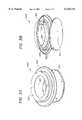
- FIGS. 5A, 5B and 5Cillustrated are sectional views of one embodiment of the microscope drape and objective lens cover of FIG. 4 along the plane 5--5 installed on three different size objective lenses.
- the resilient gasket 325 of the flexible barrel adaptor 320flexibly engages the objective lens barrel 140.
- the planar seal mount 220 and flexible barrel adaptor 320are both mechanically bonded to the sheet 210 so that the assembly may be installed in a single motion.
- FIG. 5Aillustrates installation of the microscope drape over a lens at the maximum capacity of the flexible barrel adaptor 320.
- FIG. 5Billustrates installation of the microscope drape over a lens at the minimum capacity of the flexible barrel adaptor 320.
- FIG. 5Cillustrates installation of the microscope drape over a lens employing the small lens adaptor 450 of FIGS. 4A and 4B.
- a drapeincludes: (1) a sheet, having a sheet aperture therethrough, that covers at least a portion of the surgical microscope, (2) a rigid, planar seal mount, coupled to the sheet and having a mount aperture therethrough that aligns with the sheet aperture and (3) an elastomeric sheet seal, coupled to the planar seal mount and having a dilatable seal aperture therethrough that has a constricted radius less than the mount aperture, aligns with the mount aperture, expands to receive the objective lens barrel therethrough and elastically constricts about the objective lens barrel.
Landscapes
- Health & Medical Sciences (AREA)
- Surgery (AREA)
- Physics & Mathematics (AREA)
- General Health & Medical Sciences (AREA)
- Life Sciences & Earth Sciences (AREA)
- Analytical Chemistry (AREA)
- Medical Informatics (AREA)
- Optics & Photonics (AREA)
- Chemical & Material Sciences (AREA)
- Engineering & Computer Science (AREA)
- Biomedical Technology (AREA)
- Heart & Thoracic Surgery (AREA)
- General Physics & Mathematics (AREA)
- Molecular Biology (AREA)
- Animal Behavior & Ethology (AREA)
- Public Health (AREA)
- Veterinary Medicine (AREA)
- Microscoopes, Condenser (AREA)
- Materials For Medical Uses (AREA)
Abstract
Description
Claims (21)
Priority Applications (4)
| Application Number | Priority Date | Filing Date | Title |
|---|---|---|---|
| US09/042,062US6116741A (en) | 1998-03-13 | 1998-03-13 | Surgical microscope operating drape and methods of operation and manufacture thereof |
| DE69909155TDE69909155T2 (en) | 1998-03-13 | 1999-03-11 | Masking cloth for a surgical microscope and method for operation and its production |
| EP99104900AEP0941706B1 (en) | 1998-03-13 | 1999-03-11 | Surgical microscope operating drape and methods of operation and manufacture thereof |
| AT99104900TATE243983T1 (en) | 1998-03-13 | 1999-03-11 | CLOTH FOR A SURGICAL MICROSCOPE AND METHOD OF OPERATION AND PRODUCTION THEREOF |
Applications Claiming Priority (1)
| Application Number | Priority Date | Filing Date | Title |
|---|---|---|---|
| US09/042,062US6116741A (en) | 1998-03-13 | 1998-03-13 | Surgical microscope operating drape and methods of operation and manufacture thereof |
Publications (1)
| Publication Number | Publication Date |
|---|---|
| US6116741Atrue US6116741A (en) | 2000-09-12 |
Family
ID=21919844
Family Applications (1)
| Application Number | Title | Priority Date | Filing Date |
|---|---|---|---|
| US09/042,062Expired - LifetimeUS6116741A (en) | 1998-03-13 | 1998-03-13 | Surgical microscope operating drape and methods of operation and manufacture thereof |
Country Status (4)
| Country | Link |
|---|---|
| US (1) | US6116741A (en) |
| EP (1) | EP0941706B1 (en) |
| AT (1) | ATE243983T1 (en) |
| DE (1) | DE69909155T2 (en) |
Cited By (21)
| Publication number | Priority date | Publication date | Assignee | Title |
|---|---|---|---|---|
| US20030069472A1 (en)* | 2000-03-23 | 2003-04-10 | John Butler | Insertion device for an endoscope |
| US20040190139A1 (en)* | 2003-03-24 | 2004-09-30 | Weaver Richard A. | Sterilizable drape for ophthalmoscopic lens |
| US20040190140A1 (en)* | 2003-03-24 | 2004-09-30 | Bala Andrew J. | Surgical microscope drape assembly |
| US20050063058A1 (en)* | 2003-09-22 | 2005-03-24 | Langley Nicholas M. | Glare-elimination device for surgical microscopes |
| US6876503B1 (en) | 2003-10-28 | 2005-04-05 | Contour Fabricators, Inc. | Microscope drape lens protective cover assembly |
| US20050094269A1 (en)* | 2003-10-31 | 2005-05-05 | Moses Gary L. | Microscope drape coupling system and method |
| US20100238551A1 (en)* | 2009-03-19 | 2010-09-23 | Hubbs Charles M | Surgical microscope drape lens for reducing glare |
| AU2006255079B2 (en)* | 2005-06-06 | 2011-04-07 | Abs Med Inc. | Surgical microscope drape with removable lens assembly |
| US20110155145A1 (en)* | 2009-12-29 | 2011-06-30 | Chua Mark Spencer G | Medical lens assemblies and sterile drapes with a lens assembly |
| US20140042045A1 (en)* | 2010-11-19 | 2014-02-13 | Leopold Lackner | Cover for an ultrasonic head |
| US20140158141A1 (en)* | 2012-12-12 | 2014-06-12 | Marilyn Winer | Sterile Drape for Robotic Surgical Equipment |
| USD875151S1 (en) | 2017-04-28 | 2020-02-11 | Ecolab Usa Inc. | Microscope drape |
| USD877226S1 (en) | 2017-04-28 | 2020-03-03 | Ecolab Usa Inc. | Optical lens housing |
| US10603217B2 (en)* | 2014-07-01 | 2020-03-31 | Laurence Spier | Surgical robotic instrument shield |
| US20210137626A1 (en)* | 2018-03-28 | 2021-05-13 | Aesculap Ag | Mounting adapter for securing a sterile cover on a microscope, microscope for use with an adapter of this type, and system having a microscope of this type and an adapter of this type |
| US11510747B2 (en) | 2017-05-25 | 2022-11-29 | Covidien Lp | Robotic surgical systems and drapes for covering components of robotic surgical systems |
| WO2023147702A1 (en)* | 2022-02-07 | 2023-08-10 | Mazor Robotics Ltd. | Housing for a sterile cover and a filter |
| US20230301739A1 (en)* | 2020-11-27 | 2023-09-28 | Carl Zeiss Meditec Ag | Holding element for a drape for a surgical microscope |
| US12029523B2 (en) | 2017-12-01 | 2024-07-09 | Covidien Lp | Drape management assembly for robotic surgical systems |
| US20240245159A1 (en)* | 2018-06-27 | 2024-07-25 | Stryker Corporation | Protective Apparel System With A Lens Assembly |
| US12070361B2 (en) | 2020-05-08 | 2024-08-27 | Micah Nuzum | Protective shield for surgical microscope |
Families Citing this family (4)
| Publication number | Priority date | Publication date | Assignee | Title |
|---|---|---|---|---|
| DE10250811A1 (en)* | 2002-08-16 | 2004-03-04 | Stuemed Gmbh | Microscope cover with lens ring II |
| AU2003253407A1 (en)* | 2002-08-16 | 2004-03-11 | Stuemed Gmbh | Sterile microscope coating comprising an objective adapter |
| DE10311198B4 (en)* | 2003-02-06 | 2016-09-22 | Carl Zeiss Meditec Ag | Holding device with transparent cover for drape and Drape for a surgical microscope with such a holding device |
| US20080144178A1 (en)* | 2006-12-13 | 2008-06-19 | Microtek Medical, Inc. | Microscope drape lens cover system and assembly method |
Citations (10)
| Publication number | Priority date | Publication date | Assignee | Title |
|---|---|---|---|---|
| US3528720A (en)* | 1968-12-18 | 1970-09-15 | Richards Mfg Co | Operating microscope envelope means |
| US3698791A (en)* | 1971-04-19 | 1972-10-17 | Xerox Corp | Drape for operating microscope |
| US3796477A (en)* | 1972-09-25 | 1974-03-12 | Xomox Corp | Lens housing and lens cover for objective lens ring of an operating microscope |
| US4176701A (en)* | 1978-09-28 | 1979-12-04 | Welgan Peter R | Camera rain shield |
| US4385812A (en)* | 1981-02-02 | 1983-05-31 | Surgikos, Inc. | Objective lens cover assembly for an operating microscope |
| US4799779A (en)* | 1988-03-22 | 1989-01-24 | Mesmer Jeffrey C | Microscope drape |
| US5155624A (en)* | 1990-06-25 | 1992-10-13 | Smith & Nephew Richards, Inc. | Lens housing for sterile cover of an operating microscope |
| US5311358A (en)* | 1992-10-08 | 1994-05-10 | Time Surgical, Inc. | Universal microscope drape |
| US5467223A (en)* | 1993-12-16 | 1995-11-14 | Xomed-Treace Inc. | Drape adapter |
| US5853363A (en)* | 1997-07-28 | 1998-12-29 | Deka Medical, Inc. | Surgical microscope operating drape and methods of operation and manufacture thereof |
Family Cites Families (2)
| Publication number | Priority date | Publication date | Assignee | Title |
|---|---|---|---|---|
| US4266663A (en)* | 1979-11-13 | 1981-05-12 | Carl Zeiss, Inc. | Surgical drape for an operating microscope |
| US5682264A (en)* | 1993-03-01 | 1997-10-28 | Microtek Medical, Inc. | Universal microscope drape |
- 1998
- 1998-03-13USUS09/042,062patent/US6116741A/ennot_activeExpired - Lifetime
- 1999
- 1999-03-11EPEP99104900Apatent/EP0941706B1/ennot_activeExpired - Lifetime
- 1999-03-11DEDE69909155Tpatent/DE69909155T2/ennot_activeExpired - Fee Related
- 1999-03-11ATAT99104900Tpatent/ATE243983T1/ennot_activeIP Right Cessation
Patent Citations (10)
| Publication number | Priority date | Publication date | Assignee | Title |
|---|---|---|---|---|
| US3528720A (en)* | 1968-12-18 | 1970-09-15 | Richards Mfg Co | Operating microscope envelope means |
| US3698791A (en)* | 1971-04-19 | 1972-10-17 | Xerox Corp | Drape for operating microscope |
| US3796477A (en)* | 1972-09-25 | 1974-03-12 | Xomox Corp | Lens housing and lens cover for objective lens ring of an operating microscope |
| US4176701A (en)* | 1978-09-28 | 1979-12-04 | Welgan Peter R | Camera rain shield |
| US4385812A (en)* | 1981-02-02 | 1983-05-31 | Surgikos, Inc. | Objective lens cover assembly for an operating microscope |
| US4799779A (en)* | 1988-03-22 | 1989-01-24 | Mesmer Jeffrey C | Microscope drape |
| US5155624A (en)* | 1990-06-25 | 1992-10-13 | Smith & Nephew Richards, Inc. | Lens housing for sterile cover of an operating microscope |
| US5311358A (en)* | 1992-10-08 | 1994-05-10 | Time Surgical, Inc. | Universal microscope drape |
| US5467223A (en)* | 1993-12-16 | 1995-11-14 | Xomed-Treace Inc. | Drape adapter |
| US5853363A (en)* | 1997-07-28 | 1998-12-29 | Deka Medical, Inc. | Surgical microscope operating drape and methods of operation and manufacture thereof |
Non-Patent Citations (8)
| Title |
|---|
| "Innovation By Design . . . Microscope Drapes" Technical Information sheets from Microtek Medical: 5 pages; 1994. |
| "Innovation By Design . . . Universal Microscope Drape" Technical Information Sheets from Microtek Medical for Product No. 6920; 2 pages. |
| "Microscope Drapes" Technical Information sheets on "Microdrape®" 6 pages. |
| "Opmi® Drape" Technical Information sheets from Carl Zeiss, Inc. 7 pages; 1992. |
| Innovation By Design . . . Microscope Drapes Technical Information sheets from Microtek Medical: 5 pages; 1994.* |
| Innovation By Design . . . Universal Microscope Drape Technical Information Sheets from Microtek Medical for Product No. 6920; 2 pages.* |
| Microscope Drapes Technical Information sheets on Microdrape 6 pages.* |
| Opmi Drape Technical Information sheets from Carl Zeiss, Inc. 7 pages; 1992.* |
Cited By (41)
| Publication number | Priority date | Publication date | Assignee | Title |
|---|---|---|---|---|
| US6869393B2 (en)* | 2000-03-23 | 2005-03-22 | Atropos Limited | Insertion device for an endoscope |
| US20030069472A1 (en)* | 2000-03-23 | 2003-04-10 | John Butler | Insertion device for an endoscope |
| US6902278B2 (en) | 2003-03-24 | 2005-06-07 | Andrew J. Bala | Surgical microscope drape assembly |
| US6869194B2 (en)* | 2003-03-24 | 2005-03-22 | Contour Fabricators, Inc. | Sterilizable drape for ophthalmoscopic lens |
| US20040190140A1 (en)* | 2003-03-24 | 2004-09-30 | Bala Andrew J. | Surgical microscope drape assembly |
| US20040190139A1 (en)* | 2003-03-24 | 2004-09-30 | Weaver Richard A. | Sterilizable drape for ophthalmoscopic lens |
| WO2004086101A3 (en)* | 2003-03-24 | 2005-12-01 | Abs Med Inc | Surgical microscope drape assembly |
| US20050063058A1 (en)* | 2003-09-22 | 2005-03-24 | Langley Nicholas M. | Glare-elimination device for surgical microscopes |
| US7234824B2 (en)* | 2003-09-22 | 2007-06-26 | Langley Nicholas M | Glare-elimination device for surgical microscopes |
| US6876503B1 (en) | 2003-10-28 | 2005-04-05 | Contour Fabricators, Inc. | Microscope drape lens protective cover assembly |
| US20050088763A1 (en)* | 2003-10-28 | 2005-04-28 | Contour Fabricators, Inc. | Microscope drape lens protective cover assembly |
| US20050094269A1 (en)* | 2003-10-31 | 2005-05-05 | Moses Gary L. | Microscope drape coupling system and method |
| US20060139753A1 (en)* | 2003-10-31 | 2006-06-29 | Moses Gary L | Microscope drape coupling system and method |
| AU2006255079B2 (en)* | 2005-06-06 | 2011-04-07 | Abs Med Inc. | Surgical microscope drape with removable lens assembly |
| US20100238551A1 (en)* | 2009-03-19 | 2010-09-23 | Hubbs Charles M | Surgical microscope drape lens for reducing glare |
| US8864320B2 (en) | 2009-12-29 | 2014-10-21 | Medline Industries, Inc. | Medical lens assemblies and sterile drapes with a lens assembly |
| US8506094B2 (en) | 2009-12-29 | 2013-08-13 | Medline Industries, Inc. | Medical lens assemblies and sterile drapes with a lens assembly |
| US8672489B2 (en) | 2009-12-29 | 2014-03-18 | Medline Industries, Inc. | Medical lens assemblies and sterile drapes with a lens assembly |
| US20110155145A1 (en)* | 2009-12-29 | 2011-06-30 | Chua Mark Spencer G | Medical lens assemblies and sterile drapes with a lens assembly |
| US9050085B2 (en) | 2009-12-29 | 2015-06-09 | Medline Industries, Inc. | Medical lens assemblies and sterile drapes with a lens assembly |
| US20140042045A1 (en)* | 2010-11-19 | 2014-02-13 | Leopold Lackner | Cover for an ultrasonic head |
| US9131921B2 (en)* | 2010-11-19 | 2015-09-15 | Leopold Lackner | Cover for an ultrasonic head |
| US20140158141A1 (en)* | 2012-12-12 | 2014-06-12 | Marilyn Winer | Sterile Drape for Robotic Surgical Equipment |
| US8910637B2 (en)* | 2012-12-12 | 2014-12-16 | Marilyn Winer | Sterile drape for robotic surgical equipment |
| US20150047647A1 (en)* | 2012-12-12 | 2015-02-19 | Marilyn Winer | Sterile Drape for Robotic Surgical Equipment |
| US9629680B2 (en)* | 2012-12-12 | 2017-04-25 | Ecolab Usa Inc. | Sterile drape for robotic surgical equipment |
| US10603217B2 (en)* | 2014-07-01 | 2020-03-31 | Laurence Spier | Surgical robotic instrument shield |
| USD875151S1 (en) | 2017-04-28 | 2020-02-11 | Ecolab Usa Inc. | Microscope drape |
| USD1061659S1 (en) | 2017-04-28 | 2025-02-11 | Medline Industries, Lp | Microscope drape |
| USD877226S1 (en) | 2017-04-28 | 2020-03-03 | Ecolab Usa Inc. | Optical lens housing |
| USD1033502S1 (en) | 2017-04-28 | 2024-07-02 | Ecolab Usa Inc. | Optical lens housing |
| US11510747B2 (en) | 2017-05-25 | 2022-11-29 | Covidien Lp | Robotic surgical systems and drapes for covering components of robotic surgical systems |
| US12029523B2 (en) | 2017-12-01 | 2024-07-09 | Covidien Lp | Drape management assembly for robotic surgical systems |
| US20210137626A1 (en)* | 2018-03-28 | 2021-05-13 | Aesculap Ag | Mounting adapter for securing a sterile cover on a microscope, microscope for use with an adapter of this type, and system having a microscope of this type and an adapter of this type |
| US12109002B2 (en)* | 2018-03-28 | 2024-10-08 | Digital Surgery Systems, Inc. | Mounting adapter for securing a sterile cover on a microscope, microscope for use with an adapter of this type, and system having a microscope of this type and an adapter of this type |
| US20240245159A1 (en)* | 2018-06-27 | 2024-07-25 | Stryker Corporation | Protective Apparel System With A Lens Assembly |
| US12408719B2 (en)* | 2018-06-27 | 2025-09-09 | Stryker Corporation | Protective apparel system with a lens assembly |
| US12070361B2 (en) | 2020-05-08 | 2024-08-27 | Micah Nuzum | Protective shield for surgical microscope |
| US11980437B2 (en)* | 2020-11-27 | 2024-05-14 | Carl Zeiss Meditec Ag | Holding element for a drape for a surgical microscope |
| US20230301739A1 (en)* | 2020-11-27 | 2023-09-28 | Carl Zeiss Meditec Ag | Holding element for a drape for a surgical microscope |
| WO2023147702A1 (en)* | 2022-02-07 | 2023-08-10 | Mazor Robotics Ltd. | Housing for a sterile cover and a filter |
Also Published As
| Publication number | Publication date |
|---|---|
| DE69909155D1 (en) | 2003-08-07 |
| EP0941706A1 (en) | 1999-09-15 |
| DE69909155T2 (en) | 2004-01-08 |
| EP0941706B1 (en) | 2003-07-02 |
| ATE243983T1 (en) | 2003-07-15 |
Similar Documents
| Publication | Publication Date | Title |
|---|---|---|
| US6116741A (en) | Surgical microscope operating drape and methods of operation and manufacture thereof | |
| US5853363A (en) | Surgical microscope operating drape and methods of operation and manufacture thereof | |
| KR101436664B1 (en) | Microscope Drape Lens Cover System and Assembly Method | |
| EP3029506B1 (en) | Medical lens assemblies and sterile drapes with a lens assembly | |
| US20060139753A1 (en) | Microscope drape coupling system and method | |
| US6318864B1 (en) | Sterile instruments cover for use on surgical microscopes | |
| NZ248876A (en) | Sterile disposable drape and adaptor ring system for microscope | |
| US6024454A (en) | Microscope drape system | |
| JP7361134B2 (en) | Sterile bag for pre-fitting | |
| US20180116745A1 (en) | Microscope drape for sterile environments |
Legal Events
| Date | Code | Title | Description |
|---|---|---|---|
| AS | Assignment | Owner name:DEKA MEDICAL, INCORPORATED, MISSISSIPPI Free format text:ASSIGNMENT OF ASSIGNORS INTEREST;ASSIGNOR:PASCHAL, PATTI B.;REEL/FRAME:009261/0468 Effective date:19980610 | |
| AS | Assignment | Owner name:CHASE MANHATTAN BANK, THE, NEW YORK Free format text:SECURITY AGREEMENT;ASSIGNOR:DEKA MEDICAL, INC.;REEL/FRAME:010470/0889 Effective date:19991215 | |
| STCF | Information on status: patent grant | Free format text:PATENTED CASE | |
| AS | Assignment | Owner name:DEKA MEDICAL, INC., MISSISSIPPI Free format text:RELEASE BY SECURED PARTY;ASSIGNOR:CHASE MANHATTAN BANK;REEL/FRAME:011762/0982 Effective date:20010315 Owner name:MICROTEK MEDICAL, INC., MISSISSIPPI Free format text:ASSIGNMENT OF ASSIGNORS INTEREST;ASSIGNOR:DEKA MEDICAL, INC.;REEL/FRAME:011763/0036 Effective date:20010302 | |
| AS | Assignment | Owner name:CHASE MANHATTAN BANK THE, A NEW YORK BANKING CORPO Free format text:SECURITY AGREEMENT;ASSIGNOR:MICROTEK MEDICAL, INC. A DELAWARE CORPORATION;REEL/FRAME:011869/0953 Effective date:20010514 | |
| FPAY | Fee payment | Year of fee payment:4 | |
| REMI | Maintenance fee reminder mailed | ||
| SULP | Surcharge for late payment | ||
| FPAY | Fee payment | Year of fee payment:8 | |
| FPAY | Fee payment | Year of fee payment:12 |