US6116523A - Pressure-compensating drip irrigation hose and method for its manufacture - Google Patents
Pressure-compensating drip irrigation hose and method for its manufactureDownload PDFInfo
- Publication number
- US6116523A US6116523AUS09/308,060US30806099AUS6116523AUS 6116523 AUS6116523 AUS 6116523AUS 30806099 AUS30806099 AUS 30806099AUS 6116523 AUS6116523 AUS 6116523A
- Authority
- US
- United States
- Prior art keywords
- section
- hose according
- turbulent flow
- hose
- nozzle
- Prior art date
- Legal status (The legal status is an assumption and is not a legal conclusion. Google has not performed a legal analysis and makes no representation as to the accuracy of the status listed.)
- Expired - Lifetime
Links
- 230000002262irrigationEffects0.000titleclaimsabstractdescription26
- 238000003973irrigationMethods0.000titleclaimsabstractdescription26
- 238000000034methodMethods0.000titleclaimsabstractdescription10
- 238000004519manufacturing processMethods0.000titledescription2
- 230000001105regulatory effectEffects0.000claimsabstractdescription62
- XLYOFNOQVPJJNP-UHFFFAOYSA-NwaterSubstancesOXLYOFNOQVPJJNP-UHFFFAOYSA-N0.000claimsabstractdescription57
- 239000011324beadSubstances0.000claimsdescription9
- 239000002985plastic filmSubstances0.000claimsdescription3
- 229920006255plastic filmPolymers0.000claimsdescription3
- 239000004033plasticSubstances0.000claimsdescription2
- 229920003023plasticPolymers0.000claimsdescription2
- 238000000151depositionMethods0.000claims1
- 239000000463materialSubstances0.000description4
- 238000000465mouldingMethods0.000description4
- 230000000694effectsEffects0.000description2
- 238000001125extrusionMethods0.000description2
- 239000004743PolypropyleneSubstances0.000description1
- 238000010276constructionMethods0.000description1
- 239000000356contaminantSubstances0.000description1
- 230000007423decreaseEffects0.000description1
- 238000010586diagramMethods0.000description1
- 239000013536elastomeric materialSubstances0.000description1
- 230000008020evaporationEffects0.000description1
- 238000001704evaporationMethods0.000description1
- 239000003337fertilizerSubstances0.000description1
- 229920001903high density polyethylenePolymers0.000description1
- 239000004700high-density polyethyleneSubstances0.000description1
- 238000012886linear functionMethods0.000description1
- 235000015097nutrientsNutrition0.000description1
- -1polypropylenePolymers0.000description1
- 229920001155polypropylenePolymers0.000description1
- 238000004904shorteningMethods0.000description1
- 239000008400supply waterSubstances0.000description1
- 229920002725thermoplastic elastomerPolymers0.000description1
Images


Classifications
- A—HUMAN NECESSITIES
- A01—AGRICULTURE; FORESTRY; ANIMAL HUSBANDRY; HUNTING; TRAPPING; FISHING
- A01G—HORTICULTURE; CULTIVATION OF VEGETABLES, FLOWERS, RICE, FRUIT, VINES, HOPS OR SEAWEED; FORESTRY; WATERING
- A01G25/00—Watering gardens, fields, sports grounds or the like
- A01G25/02—Watering arrangements located above the soil which make use of perforated pipe-lines or pipe-lines with dispensing fittings, e.g. for drip irrigation
- A01G25/023—Dispensing fittings for drip irrigation, e.g. drippers
- A—HUMAN NECESSITIES
- A01—AGRICULTURE; FORESTRY; ANIMAL HUSBANDRY; HUNTING; TRAPPING; FISHING
- A01G—HORTICULTURE; CULTIVATION OF VEGETABLES, FLOWERS, RICE, FRUIT, VINES, HOPS OR SEAWEED; FORESTRY; WATERING
- A01G25/00—Watering gardens, fields, sports grounds or the like
- A01G25/02—Watering arrangements located above the soil which make use of perforated pipe-lines or pipe-lines with dispensing fittings, e.g. for drip irrigation
- A01G25/026—Apparatus or processes for fitting the drippers to the hoses or the pipes
- B—PERFORMING OPERATIONS; TRANSPORTING
- B29—WORKING OF PLASTICS; WORKING OF SUBSTANCES IN A PLASTIC STATE IN GENERAL
- B29C—SHAPING OR JOINING OF PLASTICS; SHAPING OF MATERIAL IN A PLASTIC STATE, NOT OTHERWISE PROVIDED FOR; AFTER-TREATMENT OF THE SHAPED PRODUCTS, e.g. REPAIRING
- B29C53/00—Shaping by bending, folding, twisting, straightening or flattening; Apparatus therefor
- B29C53/36—Bending and joining, e.g. for making hollow articles
- B29C53/38—Bending and joining, e.g. for making hollow articles by bending sheets or strips at right angles to the longitudinal axis of the article being formed and joining the edges
- B29C53/48—Bending and joining, e.g. for making hollow articles by bending sheets or strips at right angles to the longitudinal axis of the article being formed and joining the edges for articles of indefinite length, i.e. bending a strip progressively
- B29C53/52—Bending and joining, e.g. for making hollow articles by bending sheets or strips at right angles to the longitudinal axis of the article being formed and joining the edges for articles of indefinite length, i.e. bending a strip progressively using external forming surfaces, e.g. sleeves
- B—PERFORMING OPERATIONS; TRANSPORTING
- B29—WORKING OF PLASTICS; WORKING OF SUBSTANCES IN A PLASTIC STATE IN GENERAL
- B29D—PRODUCING PARTICULAR ARTICLES FROM PLASTICS OR FROM SUBSTANCES IN A PLASTIC STATE
- B29D23/00—Producing tubular articles
- B—PERFORMING OPERATIONS; TRANSPORTING
- B29—WORKING OF PLASTICS; WORKING OF SUBSTANCES IN A PLASTIC STATE IN GENERAL
- B29C—SHAPING OR JOINING OF PLASTICS; SHAPING OF MATERIAL IN A PLASTIC STATE, NOT OTHERWISE PROVIDED FOR; AFTER-TREATMENT OF THE SHAPED PRODUCTS, e.g. REPAIRING
- B29C2793/00—Shaping techniques involving a cutting or machining operation
- B29C2793/0036—Slitting
- B—PERFORMING OPERATIONS; TRANSPORTING
- B29—WORKING OF PLASTICS; WORKING OF SUBSTANCES IN A PLASTIC STATE IN GENERAL
- B29L—INDEXING SCHEME ASSOCIATED WITH SUBCLASS B29C, RELATING TO PARTICULAR ARTICLES
- B29L2023/00—Tubular articles
- B29L2023/005—Hoses, i.e. flexible
- Y—GENERAL TAGGING OF NEW TECHNOLOGICAL DEVELOPMENTS; GENERAL TAGGING OF CROSS-SECTIONAL TECHNOLOGIES SPANNING OVER SEVERAL SECTIONS OF THE IPC; TECHNICAL SUBJECTS COVERED BY FORMER USPC CROSS-REFERENCE ART COLLECTIONS [XRACs] AND DIGESTS
- Y02—TECHNOLOGIES OR APPLICATIONS FOR MITIGATION OR ADAPTATION AGAINST CLIMATE CHANGE
- Y02A—TECHNOLOGIES FOR ADAPTATION TO CLIMATE CHANGE
- Y02A40/00—Adaptation technologies in agriculture, forestry, livestock or agroalimentary production
- Y02A40/10—Adaptation technologies in agriculture, forestry, livestock or agroalimentary production in agriculture
- Y02A40/22—Improving land use; Improving water use or availability; Controlling erosion
Definitions
- the inventionrelates to drip irrigation, and more particularly to a drip irrigation hose with pressure compensation and a method for its manufacture.
- Drip irrigation systemshave come into widespread use in the agricultural area. Drip irrigation systems supply water at a slow, controlled rate to the root zone of the particular plants being irrigated. Typically, drip irrigation is accomplished by providing a low volume water outlet at each plant that permits a limited dripping of water directly to the root zone of the particular plant. Because evaporation, runoff, overwatering, and watering beyond the root zone are eliminated, substantial water and nutrient savings are realized. In addition, drip irrigation reduces contaminants to the water table by enabling the farmer to supply only enough water and fertilizer to reach the plants, reducing excess water that would run off and contaminate the water table below.
- Drip irrigation hosestend to be relatively long to be able to extend across a field. As the water travels along the hose away from the water source, the pressure of the water decreases. Thus, the water pressure at the beginning of the hose (near the water source) is greater than that at the far end of the hose. Because the drip rate of the hose is a function of the water pressure, the drip rate at the beginning of the hose tends to be greater than at the end of the hose. Thus, it is desirable to incorporate pressure-compensating designs into the hoses to reduce the effect of the pressure difference over the length of the hose on the drip rate along the length of the hose.
- the present inventionis directed to a pressure-compensating drip irrigation hose having a water supply passage and a flow regulating channel smaller than the water supply passage.
- the flow regulating channelcomprises at least one inlet section, at least one outlet section, and at least one nozzle section between an inlet section and an outlet section.
- the inlet sectioncomprises one or more openings connecting the water supply passage to the flow regulating channel.
- the outlet sectioncomprises one or more openings connecting the flow regulating channel to the exterior of the hose.
- the flow regulating channelfurther comprises at least one turbulent flow section between an inlet section and an outlet section.
- the nozzle sectionis preferably between an inlet section and a turbulent flow section.
- the inventionis directed to pressure-compensating drip irrigation hose having a water supply passage and a flow regulating channel smaller than the water supply passage.
- the flow regulating channelcomprises one inlet section, one outlet section, two turbulent flow regions, and two nozzle sections.
- the inlet sectioncomprises a plurality of pillars with a plurality of openings between the pillars.
- the outlet sectioncomprises a slit outlet.
- the two turbulent flow sectionsare between the inlet section and the outlet section. Each turbulent flow section comprises a series of upstream-facing, nonoverlapping, interlaced chevrons, and the two turbulent flows are approximately equal in length.
- the two nozzle sectionseach comprise a fin. One nozzle section is between the inlet section and one of the turbulent flow sections and the second nozzle section is between the two turbulent flow sections.
- Another embodiment of the inventionis a drip irrigation hose having a water supply passage and a flow regulating channel smaller than the water supply passage.
- the flow regulating channelcomprises an inlet section, an outlet section, and a turbulent flow region between the inlet section and outlet section.
- the turbulent flow regioncomprises a series of resistance features that are nonoverlapping.
- the resistance featuresare interlaced, upstream-facing chevrons.
- the inventionis also directed to a method for making a pressure-compensating drip irrigation hose at an assembly station.
- the methodcomprises continuously transporting through the assembly station a first strip of plastic film having inner and outer longitudinal margins and a longitudinal central region between the margins. Outlet holes are formed along the length of the film.
- the inner marginis folded, and one or more continuous molten beads of compatible plastic are deposited onto the outside surface of the inner margins.
- the one or more beadsare formed into a flow regulating channel defined by side walls and having at least one nozzle section.
- the outer marginis folded onto the inner margin, with the flow regulating channel formed therebetween.
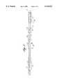
- FIG. 1is a cross-sectional view of a drip irrigation hose having a flow regulating channel between its margins.
- FIG. 2is a top sectional view of a flow regulating passage according to the invention having a nozzle section comprising a relatively long converging sidewall.
- PIG. 3is a top sectional view of a flow regulating passage according to the invention having two different-sized turbulent flow sections and two nozzle sections each comprising a fin.
- FIG. 4is a top sectional view of a flow regulating passage according to the invention having two approximately equal-sized turbulent flow sections and two nozzle sections each comprising a fin and one nozzle section also comprising an additional nozzle.
- FIG. 5is a top sectional view of a flow regulating passage according to the invention having a nozzle section comprising a relatively short converging sidewall.
- FIG. 6is a top sectional view of a flow regulating passage according to the invention having two approximately equal-sized turbulent flow sections and two nozzle sections each comprising a fin.
- FIG. 7is a top sectional view of a flow regulating passage according to the invention having three different-sized turbulent flow sections, each comprising non-overlapping chevrons, and three nozzle sections each comprising a fin.
- FIG. 8is a cross-sectional view of a drip irrigation hose containing an emitter.
- FIG. 9is a block diagram representing a method of producing a drip irrigation hose according to the present invention.
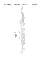
- FIG. 10is an elevated three-quarter view of an assembly station for making a drip irrigation hose according to the present invention.
- the present inventionis directed to pressure-compensating drip irrigation hoses 10 and pressure-compensating emitters 12 for use in drip irrigation hoses. Pressure-compensation is achieved by the use of nozzle sections, described in more detail below.
- a drip irrigation hose 10is made from an elongated strip of plastic film 14, which is typically 4 to 15 mil thick.
- the film 14can be made of any suitable material, for example, a laminate of high density polyethylene or polypropylene.
- Film 14is folded longitudinally to form overlapping inner and outer longitudinal margins 16 and 18, thus creating a seam.
- a first longitudinal rib 20partially seals margins 16 and 18.
- Ribs 20 and 22contain a repeating longitudinal pattern that defines a series of small flow regulating channels 24 along the length of the hose 10.
- the interior surface of film 14defines a relatively large water supply passage 26.
- the water supply passage 26is connected to a source of water under pressure, not shown. Examples of such constructions are described in U.S. Pat. Nos. 4,247,051, 4,984,739, 5,282,578, and 5,522,551, the disclosures of which are incorporated herein by reference.
- the flow regulating channels 24each have an inlet section 28, a turbulent flow section 30, an outlet section 32, and a nozzle section 34 (referred to in the provisional application as a "venturi section").
- the flow regulating channels 24each have a much smaller cross-sectional area than the water supply passage 26. Accordingly, each flow regulating channel 24 creates a passage between the water supply passage 26 and the outside of the hose 10 that reduces the pressure and controls the flow rate of the water flowing through it.
- the inlet section 28comprises one or more inlet openings to allow water to flow from the water supply passage 26 into the flow regulating channel 24.
- the inlet section 28comprises a plurality of pillars 36 between which are formed openings 38.
- the inlet section 28can have any other design that permits water to enter the flow regulating channel 24 from the water supply passage 26.
- the turbulent flow section 30comprises a turbulent flow path 40 that dissipates energy of the water by creating turbulence.
- the turbulent flow path 40is a serpentine flow path formed by a plurality of interlaced and overlapping (i.e., having a positive overlap), upstream-facing chevrons 42.
- chevronsrefers to generally chisel-shaped features, as depicted in FIG. 2.
- the turbulent flow path 40could have any other suitable design that achieves the above-stated purpose.
- the turbulent flow path 40could have any type of resistance features similar to the depicted chevrons that cause the water to divert and accelerate.
- the resistance featurescan be any suitable shape, for example, triangular, square, rectangular or rectangular having a rounded end.
- the resistance featuresPreferably, the resistance features have a pointed tip, for example, chevrons or triangular-shaped features. It is also preferred for the resistance features to be upstream-facing so as to increase the resistance.
- the nozzle section 34comprises a region that creates a nozzle effect, i.e., reduces the cross-sectional area of the water flow path and diverts the flow, thus guiding the water into a narrow channel increasing its velocity.
- the nozzle section 34comprises two sidewalls 46, with one sidewall converging toward one edge of the turbulent flow section 30.
- the converging sidewall 46increases the velocity of the water exiting the nozzle section 34.
- the resulting impact against the first chevron 42creates turbulence and a back-pressure. As the water pressure at the inlet section 28 increases, the outlet velocity increases, and thus the back pressure increases.
- both sidewalls 46can converge, either toward the middle of the flow regulating channel 24 or to one side.
- the nozzle sectioncan have sidewalls that converge to the middle of the flow regulating channel.
- the outlet section 32comprises one or more openings connecting the flow regulating channel 24 to the exterior of the hose 10.
- the outlet section 32comprises a single knife-formed slit outlet 44.
- the outlet sectioncan comprises one or more outlet holes. Any other outlet design permitting water flow to the exterior of the hose can also be used.
- a plurality of flow regulating channels 24extend along the length of the hose 10.
- the flow regulating channels 24all have the same pattern with a divider 25 between the channels.
- FIG. 2shows a relatively small divider 25 between two flow regulating channels 24.
- the flow regulating channel 24comprises two nozzle sections 34A and 34B and two turbulent flow sections 30A and 30B.
- the first nozzle section 34Aconnects the inlet section 28 to the first turbulent flow section 30A
- the second nozzle section 34Bconnects the first turbulent flow section 30A to the second turbulent flow section 30B.
- Each nozzle section 34A and 34Bcomprises an upstream-tapered fin 48.
- the fin 48forms two nozzles 50, each between the fin 48 and one of the two nozzle sidewalls 46.
- the finforms a central island around which water is accelerated.
- Each nozzle 50directs water to impact against a chevron 42 in the downstream turbulent flow section 30, thereby creating a backpressure similar to that described above.
- the second turbulent flow region 30Bis approximately one third of the size of the first turbulent flow region 30A.
- the first nozzle section 34Afurther comprises an additional nozzle 52 between the inlet section 28 and the fin 48.
- the nozzle 52is formed by two converging walls 53.
- the nozzle 52is positioned so that water flowing from its outlet impacts on the fin 48, creating a pressure-compensating back pressure.
- the length of nozzle section 34can be reduced by shortening the converging sidewall 46.
- both turbulent flow sections 30A and 30Bcan be approximately the same length, as shown in FIG. 6.
- a third turbulent flow section 30Ccan be added along with a third nozzle section 34C, whereby the lengths of the second and third turbulent flow sections are each approximately half the length of the first turbulent flow section, as depicted in FIG. 7.
- the chevrons 42can be non-overlapping, i.e., have a negative overlap, as also depicted in FIG. 7.
- the extent of average overlap between the ends of the chevronscan range, for example, from about 0.006 inch to about 0.025 inch, preferably from about 0.005 inch to about 0.020 inch.
- the average distance between the ends of the chevronscan range, for example, from about 0.004 inch to about 0.025 inch, preferably from about 0.005 inch to about 0.020 inch.
- the chevrons (or resistance features)have zero average overlap.
- the flow regulating channel 24comprises two inlet sections 28 that feed to a single outlet section 32.
- Each inlet section 28is separated from the outlet section 32 by a turbulent flow section 30.
- a general description of such a designis described in U.S. application Ser. No. 08/683,604, filed Jul. 15, 1996, the disclosure of which is incorporated herein by reference.
- a nozzle section 34such as any of those described above, can then be inserted after one or both inlet sections 28, before the corresponding turbulent flow section 30.
- flow passagescan be included in the flow regulating channels 24 of the present invention.
- an additional pressure compensating regioncould be included whereby the region comprises one or more walls made of an elastomeric material capable of deforming into the flow region, thereby reducing the cross-sectional area of the region. Examples of such designs are described in U.S. patent application Ser. No. 60/055,992, filed Aug. 18, 1997, the disclosure of which is incorporated herein by reference.
- the flow regulating channel designs of the present inventionresult in a reduced x-factor.
- X-factoris a measure of pressure compensation. Specifically, the drip flow rate of a hose is proportional to the water pressure at the inlets of the flow regulating channels raised to the exponent x. In the absence of pressure compensation, the x-factor is one, i.e., the flow rate is a linear function of the pressure. In the ideal case of perfect pressure compensation, the x-factor is zero, i.e., the flow rate is independent of pressure. Thus, a lower x-factor indicates increased pressure compensation.
- the x-factor values achieved in hoses using the inventive flow regulating channel designspreferably are less than about 0.48, more preferably are from about 0.38 to about 0.46, and still more preferably are from about 0.40 to about 0.44.
- the flow regulating channels described abovedo not have to be formed in the margin of the hose, but can be located anywhere inside or outside of the hose as desired.
- the above-described flow regulating channelscan be used in continuous and discrete emitters, which are then placed inside or outside the hose.
- an emitter 12is attached to the inside of the hose 10.
- the emitter 12comprises three walls and has a generally rectangular cross-sectional area with a fourth wall being formed by the hose 10.
- the flow regulating channel 24is contained within the three walls of the emitter 12 and the wall of the hose 10.
- the emitter 12can have four walls. Any emitter design providing a flow regulating channel 24 can be used in connection with the present invention.
- the emitters 12can be made of any material known to those skilled in the art, for example, a thermoplastic elastomer.
- the hose 10can be made of any suitable material, such as the film materials described above.
- the hose 10can be extruded through a circular die as a seamless hose.
- FIGS. 9 and 10depict a method for making the drip irrigation hose shown in FIG. 1.
- the outlets 44are first formed in film 14.
- each outlet 44comprises a single longitudinal slit in the film 14.
- a preferred method and apparatus for forming such a knife-formed slit outletis described in U.S. Pat. No. 5,522,551, the disclosure of which is incorporated herein by reference.
- the inner margin 16is then folded.
- one or more beadsare laid on the outside surface of the inner margin 14 by one or more extrusion nozzles.
- a patternis formed in ribs 20 and 22 by a molding wheel.
- outer margin 18is then folded onto inner margin 16, with the formed ribs therebetween.
- flow regulating passage 24is finished by passing inner margin 16, outer margin 18, and the ribs 20 and 22 through the nip of a form wheel and a backing wheel to set precisely the height of the ribs.
- FIG. 10illustrates an assembly station for performing the above-described steps.
- One or more extrusion nozzles 82deposit one or more continuous longitudinal beads 84 on the outside surface of the inner margin 16.
- the film 14is passed through the nip of a rotating molding wheel 86 and a rotating backing wheel 88.
- the molding wheel 86contains a pattern of depressions 90 corresponding to the desired raised rib pattern, i.e., a pattern such as those shown in FIGS. 2 to 7.
- beads 84are shaped by molding wheel 86 to form the desired bead pattern repeatedly and continuously on film 14 for the entire length of the hose 10.
- the external margin 18 of the film 14is folded by a guide 92 to overlap the inner margin 16.
- the overlapped margins of the film 14pass through the nip of a form wheel 94 and a second backing wheel 96.
- the form wheel 94has a groove 98 that depresses the ribs formed by the beads 84 to set the rib height at a specified value that determines the flow rate of the hose 10.
- the film 14is continuously transported by a conventional means, not shown.
- the disclosed wheelscould be driven, or other drive wheels could be provided, to transport the film.
Landscapes
- Life Sciences & Earth Sciences (AREA)
- Engineering & Computer Science (AREA)
- Soil Sciences (AREA)
- Water Supply & Treatment (AREA)
- Environmental Sciences (AREA)
- Mechanical Engineering (AREA)
- Nozzles (AREA)
Abstract
Description
Claims (35)
Priority Applications (1)
| Application Number | Priority Date | Filing Date | Title |
|---|---|---|---|
| US09/308,060US6116523A (en) | 1997-05-06 | 1998-05-06 | Pressure-compensating drip irrigation hose and method for its manufacture |
Applications Claiming Priority (4)
| Application Number | Priority Date | Filing Date | Title |
|---|---|---|---|
| US4576497P | 1997-05-06 | 1997-05-06 | |
| US5599297P | 1997-08-18 | 1997-08-18 | |
| US09/308,060US6116523A (en) | 1997-05-06 | 1998-05-06 | Pressure-compensating drip irrigation hose and method for its manufacture |
| PCT/US1998/009254WO1998050167A1 (en) | 1997-05-06 | 1998-05-06 | Pressure-compensating drip irrigation hose and method for its manufacture |
Publications (1)
| Publication Number | Publication Date |
|---|---|
| US6116523Atrue US6116523A (en) | 2000-09-12 |
Family
ID=26723174
Family Applications (1)
| Application Number | Title | Priority Date | Filing Date |
|---|---|---|---|
| US09/308,060Expired - LifetimeUS6116523A (en) | 1997-05-06 | 1998-05-06 | Pressure-compensating drip irrigation hose and method for its manufacture |
Country Status (3)
| Country | Link |
|---|---|
| US (1) | US6116523A (en) |
| AU (1) | AU7290798A (en) |
| WO (1) | WO1998050167A1 (en) |
Cited By (37)
| Publication number | Priority date | Publication date | Assignee | Title |
|---|---|---|---|---|
| USD450550S1 (en) | 2000-11-16 | 2001-11-20 | Roberts Group Holdings, Llc | Flow channel for drip irrigation with biased cavity |
| USD455055S1 (en) | 2000-11-16 | 2002-04-02 | Roberts Groups Holdings, Llc | Flow channel for drip irrigation with central cavity |
| US6382530B1 (en)* | 2000-07-10 | 2002-05-07 | Nelson Irrigation Corporation | Pressure compensating drip tape |
| US6568607B2 (en)* | 2001-03-16 | 2003-05-27 | The Toro Company | Emitter |
| US6736337B2 (en) | 2002-02-08 | 2004-05-18 | The Toro Company | Pressure compensating drip irrigation hose |
| US20050284966A1 (en)* | 2004-06-23 | 2005-12-29 | Defrank Michael | Emitter |
| US20070138323A1 (en)* | 2005-12-16 | 2007-06-21 | Seo Won Co., Ltd. | Drip irrigation hose |
| US20070175580A1 (en)* | 2006-01-30 | 2007-08-02 | The Toro Company | Continuous molded emitter |
| US20070242560A1 (en)* | 2006-01-18 | 2007-10-18 | Yoshihiro Norikane | Microscopic flow passage structure, microscopic liquid droplet generating method, microscopic liquid droplet generating system, particles, and microcapsules |
| US20080105768A1 (en)* | 2006-11-07 | 2008-05-08 | Eberhard Kertscher | Dosing Elements for a Drip Irrigation Tube and Method and Device for Producing these Dosing Elements |
| US20100170961A1 (en)* | 2009-01-05 | 2010-07-08 | Developmental Technologies, Llc | Uniform-Pressure Supply Line System for Varying Elevations and Associated Methods |
| US7887664B1 (en) | 2003-05-05 | 2011-02-15 | The Toro Company | Continuous molded emitter |
| CN101223856B (en)* | 2007-11-30 | 2011-05-11 | 中国科学院水利部水土保持研究所 | Anti-clogging drop irrigator with stable flow and low pressure |
| US8302887B2 (en) | 2005-03-31 | 2012-11-06 | Rain Bird Corporation | Drip emitter |
| US20140162095A1 (en)* | 2011-08-22 | 2014-06-12 | Zbb Energy Corporation | Internal Header Flow Divider for Uniform Electrolyte Distribution |
| US20150083261A1 (en)* | 2011-01-04 | 2015-03-26 | Jain Irrigation Systems, Ltd. | Apparatus and method of manufacturing pressure compensator type drip irrigation tubes with desired molecular orientation and tubes obtained thereby |
| US20150296723A1 (en)* | 2012-12-27 | 2015-10-22 | Jain Irrigation Systems Limited | Turbo tape pc for continuous flow |
| US9485923B2 (en) | 2012-03-26 | 2016-11-08 | Rain Bird Corporation | Elastomeric emitter and methods relating to same |
| JPWO2014097638A1 (en)* | 2012-12-20 | 2017-01-12 | 株式会社エンプラス | Drip irrigation dripper and drip irrigation apparatus provided with the same |
| US9743595B2 (en) | 2006-02-22 | 2017-08-29 | Rain Bird Corporation | Drip emitter |
| US9872444B2 (en) | 2013-03-15 | 2018-01-23 | Rain Bird Corporation | Drip emitter |
| US9877442B2 (en) | 2012-03-26 | 2018-01-30 | Rain Bird Corporation | Drip line and emitter and methods relating to same |
| US9877440B2 (en) | 2012-03-26 | 2018-01-30 | Rain Bird Corporation | Elastomeric emitter and methods relating to same |
| US9883640B2 (en) | 2013-10-22 | 2018-02-06 | Rain Bird Corporation | Methods and apparatus for transporting elastomeric emitters and/or manufacturing drip lines |
| USD811179S1 (en) | 2013-08-12 | 2018-02-27 | Rain Bird Corporation | Emitter part |
| US10285342B2 (en) | 2013-08-12 | 2019-05-14 | Rain Bird Corporation | Elastomeric emitter and methods relating to same |
| US10330559B2 (en) | 2014-09-11 | 2019-06-25 | Rain Bird Corporation | Methods and apparatus for checking emitter bonds in an irrigation drip line |
| US10375904B2 (en) | 2016-07-18 | 2019-08-13 | Rain Bird Corporation | Emitter locating system and related methods |
| US10440903B2 (en) | 2012-03-26 | 2019-10-15 | Rain Bird Corporation | Drip line emitter and methods relating to same |
| US10626998B2 (en) | 2017-05-15 | 2020-04-21 | Rain Bird Corporation | Drip emitter with check valve |
| US10631473B2 (en) | 2013-08-12 | 2020-04-28 | Rain Bird Corporation | Elastomeric emitter and methods relating to same |
| USD883048S1 (en) | 2017-12-12 | 2020-05-05 | Rain Bird Corporation | Emitter part |
| US11051466B2 (en) | 2017-01-27 | 2021-07-06 | Rain Bird Corporation | Pressure compensation members, emitters, drip line and methods relating to same |
| US11284572B2 (en) | 2014-12-05 | 2022-03-29 | Pivot Pup Irrigation, LLC | Irrigating soils and crops |
| US11497178B2 (en) | 2019-06-14 | 2022-11-15 | The Toro Company | Drip irrigation emitter with optimized clog resistance |
| US11985924B2 (en) | 2018-06-11 | 2024-05-21 | Rain Bird Corporation | Emitter outlet, emitter, drip line and methods relating to same |
| US12207599B2 (en) | 2021-10-12 | 2025-01-28 | Rain Bird Corporation | Emitter coupler and irrigation system |
Families Citing this family (7)
| Publication number | Priority date | Publication date | Assignee | Title |
|---|---|---|---|---|
| ZA984154B (en) | 1997-08-18 | 1998-11-26 | T Systems Int Inc | Pressure compensating drip irrigation hose and method for its manufacture |
| IL143253A0 (en)* | 1998-11-20 | 2002-04-21 | T Systems Int Inc | Drip irrigation hose with emitters having different discharge rates |
| AU1234101A (en)* | 1999-10-29 | 2001-05-14 | Rodney Ruskin | Improving the long-term diffusion rate of controlled release herbicides in thin-walled drip irrigation lines |
| MX2016005607A (en)* | 2013-10-28 | 2016-07-19 | Jain Irrigation Systems Ltd | Drip irrigation hose with outboard parallel inlets. |
| KR102191010B1 (en)* | 2018-07-24 | 2020-12-15 | 남경이엔지 주식회사 | The belt drip for emitting pipe |
| CN109324642B (en)* | 2018-10-11 | 2024-03-19 | 华北水利水电大学 | Constant outflow method and structure |
| US11452269B2 (en) | 2019-06-14 | 2022-09-27 | The Toro Company | Rail tuned pressure responsive irrigation emitter |
Citations (6)
| Publication number | Priority date | Publication date | Assignee | Title |
|---|---|---|---|---|
| US4984739A (en)* | 1986-08-04 | 1991-01-15 | Davies Allport | Drip irrigation hose |
| US5123984A (en)* | 1990-08-17 | 1992-06-23 | T-Systems International, Inc. | Method and apparatus for forming ports in drip irrigation hose |
| US5282578A (en)* | 1993-02-08 | 1994-02-01 | T-Systems International, Inc. | Self-protecting irrigation hose and method |
| US5522551A (en)* | 1993-05-26 | 1996-06-04 | T-Systems International, Inc. | Drip irrigation hose and method for its manufacture |
| US5673852A (en)* | 1988-02-16 | 1997-10-07 | Roberts; James C. | Drip irrigation tape and method of manufacture |
| US5732887A (en)* | 1988-02-16 | 1998-03-31 | Roberts; James C. | Drip irrigation tape and method of manufacture |
- 1998
- 1998-05-06WOPCT/US1998/009254patent/WO1998050167A1/enactiveApplication Filing
- 1998-05-06AUAU72907/98Apatent/AU7290798A/ennot_activeAbandoned
- 1998-05-06USUS09/308,060patent/US6116523A/ennot_activeExpired - Lifetime
Patent Citations (7)
| Publication number | Priority date | Publication date | Assignee | Title |
|---|---|---|---|---|
| US4984739A (en)* | 1986-08-04 | 1991-01-15 | Davies Allport | Drip irrigation hose |
| US5673852A (en)* | 1988-02-16 | 1997-10-07 | Roberts; James C. | Drip irrigation tape and method of manufacture |
| US5732887A (en)* | 1988-02-16 | 1998-03-31 | Roberts; James C. | Drip irrigation tape and method of manufacture |
| US5123984A (en)* | 1990-08-17 | 1992-06-23 | T-Systems International, Inc. | Method and apparatus for forming ports in drip irrigation hose |
| US5282578A (en)* | 1993-02-08 | 1994-02-01 | T-Systems International, Inc. | Self-protecting irrigation hose and method |
| US5364032A (en)* | 1993-02-08 | 1994-11-15 | T-Systems International, Inc. | Self-protecting irrigation hose and method |
| US5522551A (en)* | 1993-05-26 | 1996-06-04 | T-Systems International, Inc. | Drip irrigation hose and method for its manufacture |
Cited By (61)
| Publication number | Priority date | Publication date | Assignee | Title |
|---|---|---|---|---|
| US6382530B1 (en)* | 2000-07-10 | 2002-05-07 | Nelson Irrigation Corporation | Pressure compensating drip tape |
| USD450550S1 (en) | 2000-11-16 | 2001-11-20 | Roberts Group Holdings, Llc | Flow channel for drip irrigation with biased cavity |
| USD455055S1 (en) | 2000-11-16 | 2002-04-02 | Roberts Groups Holdings, Llc | Flow channel for drip irrigation with central cavity |
| US6568607B2 (en)* | 2001-03-16 | 2003-05-27 | The Toro Company | Emitter |
| US6736337B2 (en) | 2002-02-08 | 2004-05-18 | The Toro Company | Pressure compensating drip irrigation hose |
| US7887664B1 (en) | 2003-05-05 | 2011-02-15 | The Toro Company | Continuous molded emitter |
| US20050284966A1 (en)* | 2004-06-23 | 2005-12-29 | Defrank Michael | Emitter |
| US8302887B2 (en) | 2005-03-31 | 2012-11-06 | Rain Bird Corporation | Drip emitter |
| US20070138323A1 (en)* | 2005-12-16 | 2007-06-21 | Seo Won Co., Ltd. | Drip irrigation hose |
| US20070242560A1 (en)* | 2006-01-18 | 2007-10-18 | Yoshihiro Norikane | Microscopic flow passage structure, microscopic liquid droplet generating method, microscopic liquid droplet generating system, particles, and microcapsules |
| US8821006B2 (en)* | 2006-01-18 | 2014-09-02 | Ricoh Company, Ltd. | Microscopic flow passage structure, microscopic liquid droplet generating method, microscopic liquid droplet generating system, particles, and microcapsules |
| US20070175580A1 (en)* | 2006-01-30 | 2007-08-02 | The Toro Company | Continuous molded emitter |
| US8469294B2 (en) | 2006-01-30 | 2013-06-25 | The Toro Company | Continuous molded emitter |
| US9743595B2 (en) | 2006-02-22 | 2017-08-29 | Rain Bird Corporation | Drip emitter |
| US10842090B2 (en) | 2006-02-22 | 2020-11-24 | Rain Bird Corporation | Drip emitter |
| US20080105768A1 (en)* | 2006-11-07 | 2008-05-08 | Eberhard Kertscher | Dosing Elements for a Drip Irrigation Tube and Method and Device for Producing these Dosing Elements |
| CN101223856B (en)* | 2007-11-30 | 2011-05-11 | 中国科学院水利部水土保持研究所 | Anti-clogging drop irrigator with stable flow and low pressure |
| US20100170961A1 (en)* | 2009-01-05 | 2010-07-08 | Developmental Technologies, Llc | Uniform-Pressure Supply Line System for Varying Elevations and Associated Methods |
| US20150083261A1 (en)* | 2011-01-04 | 2015-03-26 | Jain Irrigation Systems, Ltd. | Apparatus and method of manufacturing pressure compensator type drip irrigation tubes with desired molecular orientation and tubes obtained thereby |
| AU2019204243B2 (en)* | 2011-01-04 | 2021-05-27 | Jain Irrigation Systems Limited | A pressure compensator-type drip irrigation tube |
| US9403331B2 (en)* | 2011-01-04 | 2016-08-02 | Jain Irrigation System, Ltd. | Apparatus and method of manufacturing pressure compensator type drip irrigation tubes with desired molecular orientation and tubes obtained thereby |
| AU2012204739B2 (en)* | 2011-01-04 | 2017-06-08 | Jain Irrigation Systems Limited | Apparatus and method of manufacturing pressure compensator type drip irrigation tubes with desired molecular orientation and tubes obtained thereby |
| US20140162095A1 (en)* | 2011-08-22 | 2014-06-12 | Zbb Energy Corporation | Internal Header Flow Divider for Uniform Electrolyte Distribution |
| US9577242B2 (en)* | 2011-08-22 | 2017-02-21 | Ensync, Inc. | Internal header flow divider for uniform electrolyte distribution |
| US9877441B2 (en) | 2012-03-26 | 2018-01-30 | Rain Bird Corporation | Elastomeric emitter and methods relating to same |
| US20180116134A1 (en)* | 2012-03-26 | 2018-05-03 | Rain Bird Corporation | Elastomeric emitter and methods relating to same |
| US10440903B2 (en) | 2012-03-26 | 2019-10-15 | Rain Bird Corporation | Drip line emitter and methods relating to same |
| US11185021B2 (en)* | 2012-03-26 | 2021-11-30 | Rain Bird Corporation | Elastomeric emitter and methods relating to same |
| US9877442B2 (en) | 2012-03-26 | 2018-01-30 | Rain Bird Corporation | Drip line and emitter and methods relating to same |
| US9877440B2 (en) | 2012-03-26 | 2018-01-30 | Rain Bird Corporation | Elastomeric emitter and methods relating to same |
| US9485923B2 (en) | 2012-03-26 | 2016-11-08 | Rain Bird Corporation | Elastomeric emitter and methods relating to same |
| US9883639B2 (en)* | 2012-12-20 | 2018-02-06 | Enplas Corporation | Drip-irrigation emitter and drip-irrigation device provided therewith |
| JPWO2014097638A1 (en)* | 2012-12-20 | 2017-01-12 | 株式会社エンプラス | Drip irrigation dripper and drip irrigation apparatus provided with the same |
| US11653603B2 (en)* | 2012-12-27 | 2023-05-23 | Jain Irrigation Systems Limited | Turbo tape PC for continuous flow |
| CN105025700B (en)* | 2012-12-27 | 2017-09-29 | 耆那灌溉系统有限公司 | Vortex strip pressure compensation for continuous stream |
| US20150296723A1 (en)* | 2012-12-27 | 2015-10-22 | Jain Irrigation Systems Limited | Turbo tape pc for continuous flow |
| CN105025700A (en)* | 2012-12-27 | 2015-11-04 | 耆那灌溉系统有限公司 | Vortex for continuous flow with pressure compensation |
| AU2017235966B2 (en)* | 2012-12-27 | 2019-06-27 | Jain Irrigation Systems Limited | Turbo tape PC for continuous flow |
| US9872444B2 (en) | 2013-03-15 | 2018-01-23 | Rain Bird Corporation | Drip emitter |
| US10631473B2 (en) | 2013-08-12 | 2020-04-28 | Rain Bird Corporation | Elastomeric emitter and methods relating to same |
| US10285342B2 (en) | 2013-08-12 | 2019-05-14 | Rain Bird Corporation | Elastomeric emitter and methods relating to same |
| USD811179S1 (en) | 2013-08-12 | 2018-02-27 | Rain Bird Corporation | Emitter part |
| USD826662S1 (en) | 2013-08-12 | 2018-08-28 | Rain Bird Corporation | Emitter inlet |
| US9883640B2 (en) | 2013-10-22 | 2018-02-06 | Rain Bird Corporation | Methods and apparatus for transporting elastomeric emitters and/or manufacturing drip lines |
| US10420293B2 (en) | 2013-10-22 | 2019-09-24 | Rain Bird Corporation | Methods and apparatus for transporting emitters and/or manufacturing drip line |
| US10330559B2 (en) | 2014-09-11 | 2019-06-25 | Rain Bird Corporation | Methods and apparatus for checking emitter bonds in an irrigation drip line |
| US12174091B2 (en) | 2014-09-11 | 2024-12-24 | Rain Bird Corporation | Methods and apparatus for checking emitter bonds in an irrigation drip line |
| US11422055B2 (en) | 2014-09-11 | 2022-08-23 | Rain Bird Corporation | Methods and apparatus for checking emitter bonds in an irrigation drip line |
| US11284572B2 (en) | 2014-12-05 | 2022-03-29 | Pivot Pup Irrigation, LLC | Irrigating soils and crops |
| US10750684B2 (en) | 2016-07-18 | 2020-08-25 | Rain Bird Corporation | Emitter locating system and related methods |
| US10375904B2 (en) | 2016-07-18 | 2019-08-13 | Rain Bird Corporation | Emitter locating system and related methods |
| US11051466B2 (en) | 2017-01-27 | 2021-07-06 | Rain Bird Corporation | Pressure compensation members, emitters, drip line and methods relating to same |
| US20210289722A1 (en)* | 2017-01-27 | 2021-09-23 | Rain Bird Corporation | Pressure compensation members, emitters, drip line and methods relating to same |
| US12041889B2 (en)* | 2017-01-27 | 2024-07-23 | Rain Bird Corporation | Pressure compensation members, emitters, drip line and methods relating to same |
| US10626998B2 (en) | 2017-05-15 | 2020-04-21 | Rain Bird Corporation | Drip emitter with check valve |
| USD978637S1 (en) | 2017-12-12 | 2023-02-21 | Rain Bird Corporation | Emitter part |
| USD883048S1 (en) | 2017-12-12 | 2020-05-05 | Rain Bird Corporation | Emitter part |
| US11985924B2 (en) | 2018-06-11 | 2024-05-21 | Rain Bird Corporation | Emitter outlet, emitter, drip line and methods relating to same |
| US12342766B2 (en) | 2018-06-11 | 2025-07-01 | Rain Bird Corporation | Emitter outlet, emitter, drip line and methods relating to same |
| US11497178B2 (en) | 2019-06-14 | 2022-11-15 | The Toro Company | Drip irrigation emitter with optimized clog resistance |
| US12207599B2 (en) | 2021-10-12 | 2025-01-28 | Rain Bird Corporation | Emitter coupler and irrigation system |
Also Published As
| Publication number | Publication date |
|---|---|
| AU7290798A (en) | 1998-11-27 |
| WO1998050167A1 (en) | 1998-11-12 |
Similar Documents
| Publication | Publication Date | Title |
|---|---|---|
| US6116523A (en) | Pressure-compensating drip irrigation hose and method for its manufacture | |
| AU757508B2 (en) | Drip irrigation hose with emitters having different discharge rates | |
| US5522551A (en) | Drip irrigation hose and method for its manufacture | |
| US4473191A (en) | Drip irrigation system employing flow regulation | |
| US5865377A (en) | Drip irrigation hose and method for its manufacture | |
| EP0129151B1 (en) | Process for making drip irrigation lines | |
| US4642152A (en) | Drip irrigation system employing flow regulation | |
| US5333793A (en) | Drip irrigation hose with pressure compensation and method for its manufacture | |
| US6015102A (en) | External emitter for drip irrigation hose | |
| AU675718B2 (en) | Drip irrigation hose and method for its manufacture | |
| US4726520A (en) | Continuous tube emitter | |
| WO1999002273A1 (en) | Unibody pressure-compensating emitter | |
| CA1186006A (en) | Drip irrigation system employing adjacently arranged flow-restricting passages | |
| US5634595A (en) | Drip irrigation hose and method for its manufacture | |
| JPS605810Y2 (en) | irrigation hose | |
| AU734482B2 (en) | External emitter for drip irrigation hose | |
| IL104430A (en) | Drip irrigation system employing flow regulation | |
| IL117428A (en) | Apparatus and method for manufacturing drip irrigation hose |
Legal Events
| Date | Code | Title | Description |
|---|---|---|---|
| AS | Assignment | Owner name:T-SYSTEMS INTERNATIONAL, INC., CALIFORNIA Free format text:ASSIGNMENT OF ASSIGNORS INTEREST;ASSIGNORS:CABAHUG, JAIME;TRAN, QUE;TEEGARDIN, DAVID;AND OTHERS;REEL/FRAME:010440/0820;SIGNING DATES FROM 19991112 TO 19991129 | |
| STCF | Information on status: patent grant | Free format text:PATENTED CASE | |
| CC | Certificate of correction | ||
| FEPP | Fee payment procedure | Free format text:PAT HOLDER CLAIMS SMALL ENTITY STATUS, ENTITY STATUS SET TO SMALL (ORIGINAL EVENT CODE: LTOS); ENTITY STATUS OF PATENT OWNER: SMALL ENTITY | |
| FPAY | Fee payment | Year of fee payment:4 | |
| FPAY | Fee payment | Year of fee payment:8 | |
| FPAY | Fee payment | Year of fee payment:12 | |
| AS | Assignment | Owner name:JOHN DEERE WATER, INC., CALIFORNIA Free format text:CHANGE OF NAME;ASSIGNOR:JOHN DEERE WATER TECHNOLOGIES, INC.;REEL/FRAME:034737/0637 Effective date:20091214 Owner name:JOHN DEERE WATER TECHNOLOGIES, INC., CALIFORNIA Free format text:CHANGE OF NAME;ASSIGNOR:T-SYSTEMS INTERNATIONAL, INC.;REEL/FRAME:034737/0628 Effective date:20090602 |