US6115659A - Triggering process for passive safety devices in vehicles - Google Patents
Triggering process for passive safety devices in vehiclesDownload PDFInfo
- Publication number
- US6115659A US6115659AUS08/855,645US85564597AUS6115659AUS 6115659 AUS6115659 AUS 6115659AUS 85564597 AUS85564597 AUS 85564597AUS 6115659 AUS6115659 AUS 6115659A
- Authority
- US
- United States
- Prior art keywords
- vehicle
- process according
- signals
- sensor signals
- sensor
- Prior art date
- Legal status (The legal status is an assumption and is not a legal conclusion. Google has not performed a legal analysis and makes no representation as to the accuracy of the status listed.)
- Expired - Lifetime
Links
- 238000000034methodMethods0.000titleclaimsabstractdescription37
- 230000008569processEffects0.000titleclaimsabstractdescription33
- 238000011156evaluationMethods0.000claimsabstractdescription40
- 230000001133accelerationEffects0.000claimsabstractdescription39
- 230000004913activationEffects0.000claimsabstractdescription8
- 238000001514detection methodMethods0.000claimsabstractdescription5
- 238000011002quantificationMethods0.000claimsdescription17
- 239000011159matrix materialSubstances0.000claimsdescription15
- 238000012432intermediate storageMethods0.000claimsdescription6
- 101100003180Colletotrichum lindemuthianum ATG1 geneProteins0.000claimsdescription4
- 230000010354integrationEffects0.000claimsdescription4
- 230000035945sensitivityEffects0.000claimsdescription4
- 230000004069differentiationEffects0.000claimsdescription2
- 231100001261hazardousToxicity0.000abstract1
- 230000006870functionEffects0.000description32
- 239000013598vectorSubstances0.000description25
- 239000003795chemical substances by applicationSubstances0.000description6
- 230000001960triggered effectEffects0.000description5
- 238000010586diagramMethods0.000description4
- 238000003745diagnosisMethods0.000description2
- 230000000694effectsEffects0.000description2
- 238000012854evaluation processMethods0.000description2
- 230000003321amplificationEffects0.000description1
- 230000000052comparative effectEffects0.000description1
- 230000006378damageEffects0.000description1
- 101150047356dec-1 geneProteins0.000description1
- 230000003247decreasing effectEffects0.000description1
- 238000001914filtrationMethods0.000description1
- 230000006872improvementEffects0.000description1
- 230000005055memory storageEffects0.000description1
- 238000003199nucleic acid amplification methodMethods0.000description1
- 230000002250progressing effectEffects0.000description1
- 230000004044responseEffects0.000description1
- 238000003860storageMethods0.000description1
- 230000036962time dependentEffects0.000description1
Images


Classifications
- B—PERFORMING OPERATIONS; TRANSPORTING
- B60—VEHICLES IN GENERAL
- B60R—VEHICLES, VEHICLE FITTINGS, OR VEHICLE PARTS, NOT OTHERWISE PROVIDED FOR
- B60R21/00—Arrangements or fittings on vehicles for protecting or preventing injuries to occupants or pedestrians in case of accidents or other traffic risks
- B60R21/01—Electrical circuits for triggering passive safety arrangements, e.g. airbags, safety belt tighteners, in case of vehicle accidents or impending vehicle accidents
- B60R21/013—Electrical circuits for triggering passive safety arrangements, e.g. airbags, safety belt tighteners, in case of vehicle accidents or impending vehicle accidents including means for detecting collisions, impending collisions or roll-over
- B60R21/0132—Electrical circuits for triggering passive safety arrangements, e.g. airbags, safety belt tighteners, in case of vehicle accidents or impending vehicle accidents including means for detecting collisions, impending collisions or roll-over responsive to vehicle motion parameters, e.g. to vehicle longitudinal or transversal deceleration or speed value
- G—PHYSICS
- G01—MEASURING; TESTING
- G01P—MEASURING LINEAR OR ANGULAR SPEED, ACCELERATION, DECELERATION, OR SHOCK; INDICATING PRESENCE, ABSENCE, OR DIRECTION, OF MOVEMENT
- G01P15/00—Measuring acceleration; Measuring deceleration; Measuring shock, i.e. sudden change of acceleration
- G01P15/02—Measuring acceleration; Measuring deceleration; Measuring shock, i.e. sudden change of acceleration by making use of inertia forces using solid seismic masses
- G01P15/08—Measuring acceleration; Measuring deceleration; Measuring shock, i.e. sudden change of acceleration by making use of inertia forces using solid seismic masses with conversion into electric or magnetic values
- G01P15/0891—Measuring acceleration; Measuring deceleration; Measuring shock, i.e. sudden change of acceleration by making use of inertia forces using solid seismic masses with conversion into electric or magnetic values with indication of predetermined acceleration values
- B—PERFORMING OPERATIONS; TRANSPORTING
- B60—VEHICLES IN GENERAL
- B60R—VEHICLES, VEHICLE FITTINGS, OR VEHICLE PARTS, NOT OTHERWISE PROVIDED FOR
- B60R21/00—Arrangements or fittings on vehicles for protecting or preventing injuries to occupants or pedestrians in case of accidents or other traffic risks
- B60R21/01—Electrical circuits for triggering passive safety arrangements, e.g. airbags, safety belt tighteners, in case of vehicle accidents or impending vehicle accidents
- B60R21/013—Electrical circuits for triggering passive safety arrangements, e.g. airbags, safety belt tighteners, in case of vehicle accidents or impending vehicle accidents including means for detecting collisions, impending collisions or roll-over
- B60R21/0132—Electrical circuits for triggering passive safety arrangements, e.g. airbags, safety belt tighteners, in case of vehicle accidents or impending vehicle accidents including means for detecting collisions, impending collisions or roll-over responsive to vehicle motion parameters, e.g. to vehicle longitudinal or transversal deceleration or speed value
- B60R2021/01322—Electrical circuits for triggering passive safety arrangements, e.g. airbags, safety belt tighteners, in case of vehicle accidents or impending vehicle accidents including means for detecting collisions, impending collisions or roll-over responsive to vehicle motion parameters, e.g. to vehicle longitudinal or transversal deceleration or speed value comprising variable thresholds, e.g. depending from other collision parameters
Definitions
- the inventionconcerns a process for triggering a passive safety device for vehicle occupants inside a vehicle where--by means of electric sensors that detect a critical vehicle condition, an evaluation circuit, and a triggering agent--an activation of these triggering agents is effected in relation to the acceleration signals generated by the sensors.
- Passive safety devices for motor vehiclessuch as e.g. airbag systems, pretensioning systems, or roll-over bars, serve to protect vehicle passengers from injuries in the event of a vehicle collision (crash) occurring.
- Known triggering processes of such safety deviceswill feed the acceleration signals, which are generated either by a single or even by two acceleration sensors, into integration in order to compare then the integration value with a crash threshold, and subsequently trigger the passive safety device if necessary.
- acceleration signalsBefore acceleration signals are integrated these will usually be amplified, filtered, and fed to an unsymmetrical limiter as known from DE 38 16 587 A1. By means of a differential circuit a reference value will be subtracted from any signal generated in this way; and only then will it be fed into an integrator. Further processing of the integrated acceleration signal is effected by means of analog technology.
- acceleration signalsIn addition to the analog processing of acceleration signals, their digital processing is also known, for example from DE 37 17 427. There, the acceleration signals of two sensors will be fed into a sample and hold circuit after amplification and filtering; the output signals of such a sample and hold circuit are digitized by means of a post-connected A/D converter. These digitized sensor signals are then processed by a microprocessor.
- Such digital processingis also known from DE 30 01 780 C2 where the acceleration signals are converted by means of an 8 bit analog/digital converter and processed by an 8 bit processor.
- the object of the inventionis to provide a process of the type described above which requires only a narrow bit width for processing the acceleration signals and which can therefore be implemented with low software and hardware requirements.
- the sensor signals supplied by the acceleration sensorswill be quantified by comparing the values of these acceleration signals to threshold values and then detecting those sensor signals that simultaneously indicate an impact direction opposite to the direction in which the vehicle is traveling.
- the detection of such successive sensor signals within a time sequencewill generate an increasing crash signal on the one hand, and, on the other hand, a trigger threshold which increases ever more strongly as time progresses, and, in fact, preferably increases exponentially, with trigger agents being activated as soon as the crash signal reaches this dynamic trigger threshold.
- the process according to this inventionwill cause a fast activation in time so that there will be no time delay relative to the required trigger point in time following the start of the crash event.
- the process according to this inventionallows a low cost technical circuit implementation.
- digital processing of the sensor signalsis an option here as, for example, when two sensors complete with two thresholds are used for quantification a maximum of 4 bits only need to be processed together. This low bit width is made possible by the large input quantification so that the dynamic trigger threshold can also be generated by digital means.
- implementation of the process steps following quantificationmay also be effected by means of an existing processor or an additional mini-processor (4 bit).
- the generation of the dynamic trigger thresholdwill be formed additively from a constant value and a count value increasing with the time pulse of the time pattern.
- the trigger thresholdmay be set such that it is small at the beginning and then increases exponentially in line with the specified time pattern. In this way it is ensured that immediately before the start of a crash event there exists a high sensitivity for the activation of the trigger agents in respect of the safety devices.
- the sensor signals--in a further advantageous embodiment of the invention--will be buffered during a time pulse in order to ensure subsequent processing of these signal-defined states.
- a further advantageous application of the inventionprovides for subjecting the quantified sensor signals to an evaluation function for generating sensor signal characteristics. Subsequently, these sensor signal characteristics will be differentiated and their amounts up-integrated. These up-integrated amounts will be compared with a trigger threshold and, if necessary, the trigger agents of the safety devices will then be triggered.
- adding the quantified sensor signalscan be effected as an evaluation function.
- an evaluation matrixinstead of such adding it is also possible to provide for an evaluation matrix to be used as an evaluation function; this is done by allocating a matrix value to the quantified sensor signals generated with each time pulse.
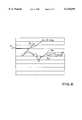
- a device for implementing the process according to the inventioncomprises two sensors arranged such in the vehicle that their sensitivity axes are located at an angle of +45° or -45° against the longitudinal axis of the vehicle in the direction of travel.
- two quantification comparatorseach will be allocated that detect a negative or positive threshold value respectively. Furthermore, for detecting such acceleration signals that indicate an impact direction against the direction of travel, a comparator will be used which then generates an output signal if the quantified sensor signals of a time pulse together show positive signs.
- the crash signalwill be implemented by means of a counter unit post-connected to the comparator such that with successive output signals of the comparator this counter unit counts up.
- the increasing trigger thresholdwill be implemented by means of a function unit that is operated as a shift register as well as a counter unit.
- An adding stagewill be post-connected to this function unit in which a constant value and a time-dependent counter value will be added up as a dynamic trigger threshold.
- the associated shift or counter pulseis generated by a divider stage.
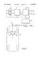
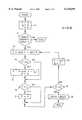
- FIG. 1A block circuit diagram for an airbag control unit as an embodiment of the process according to the invention
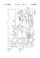
- FIG. 2a circuit layout for evaluation unit 1 according to FIG. 1,
- FIG. 3an illustration of the sensors as they are arranged in the vehicle
- FIG. 4an evaluation unit 1 according to FIG. 1 built up by means of a processor
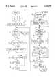
- FIG. 5a program flow chart for implementing the process according to the invention by means of a processor according to FIG. 4,
- FIG. 6a signal diagram for describing the process according to the invention
- FIG. 7a block circuit diagram of a further embodiment for implementing the process according to the invention.
- FIG. 8a program flow chart for software implementation of the circuit layout function according to FIG. 7,
- FIG. 9a part illustration of the circuit layout according to FIG. 7 complete with an evaluation matrix instead of the adding stage 17, and
- FIGS. 10a and 10bembodiments of an evaluation matrix serving as an evaluation function.
- FIG. 1shows an airbag control unit for motor vehicles complete with function blocks evaluation unit 1, power unit 2, and a diagnosis computer 3.
- the acceleration signals supplied by two acceleration sensors S1 and S2are fed into evaluation unit 1 for evaluation; based on these sensor signals, evaluation unit 1 will determine the vehicle state. If these acceleration signals indicate an impending vehicle crash, ignition commands will be passed via line 1a to power unit 2. If it receives ignition commands, this power unit will generate ignition signals for the trigger agents of airbags 2b, pretensioning system 2a, and buckle switch 2c.
- the diagnosis computer 3monitors and checks the functionality of the entire system.
- the sensors S1 and S2are offset against each other by 90°, and, respectively, by 45° against the direction of travel P in vehicle F, so that the sensor signals also provide information with regard to the direction of impact.
- evaluation unit 1A hardware implementation of evaluation unit 1 according to FIG. 1 is shown in FIG. 2 and comprises a quantification unit 4 and an evaluation circuit 5.
- the acceleration signal of sensor S1will be fed respectively into two comparators K11 and K12, and the sensor signals of sensor S2 into two further comparators K21 and K22.
- a positive and a negative threshold s1n, s1p or s2n, s2pare used as thresholds for quantification:
- the output of quantification unit 4thus has 4 lines 4a that are applied to the input of an intermediate storage device 6 designed with D flip flops.
- This comparator 7is used to check whether the sensor values--as present and quantified in each time pulse--of sensors S1 and S2 are positive (that is, whether they indicate an impact direction against the direction of vehicle travel). If this is the case, a start impulse is fed via a line 7a into a counter 8 as well as into a function unit 10 that can be operated either as a shift register or as a counter. At the same time this start impulse is applied to a NAND gate 9 which, on receiving an appropriate input signal, generates a reset signal for counter 8 via a line 9a.
- this counter 8such a start signal has the effect that its counter state Z is increased by "1". In the other case, that is, if both sensor values are not positive, the counter will be reset to "0". In this way, this counter 8 counts those sensor value pairs which successively indicate an acceleration in a positive direction, that is, which fall into the first quadrant.
- the counter state Z of this counter 8now serves as a crash signal and is fed via a line 8a into a further comparator 11 which effects a comparison with the dynamic trigger threshold (R+K1). If this trigger threshold (R+K1) is exceeded by the crash signal Z, the trigger agents of the safety devices will be activated.
- This shiftable trigger threshold (R+K1)is generated within an adding stage 12 by adding a count value R coming via a line 10a from function unit 10 and increasing in line with the clock pulse to a start value K1 entered via a line 15a of a RAM register 15.
- the count value R generated by function unit 10must increase exponentially in line with the clock pulse.
- Thisis implemented in combination with a divider stage 13 which, via a line 15b, receives a divider factor n from RAM register 15 as well as, simultaneously, the clock pulse signal clk. This generates a clock pulse signal clk1 with a lower comparative clock frequency than clock pulse signal clk.
- divider factor nthe increase of the exponential trigger threshold can be varied and thus adapted to the vehicle signature.
- sensor signalscan also be evaluated by means of a simple 4 bit processor.
- evaluation unit 1thus comprises a quantification unit 4 and a microprocessor ⁇ P.
- the other function unitscorrespond to those from FIG. 1.
- a counter function Z, a divider function n, and a register content Rwill be set to "0" in step 1.
- the meaning of functions Z and Rhas already been described in connection with the explanation relative to FIG. 2.
- start value K1is set whose meaning has also been further explained in connection with FIG. 2.
- step 3If the safety devices are operational (compare step 3), it will be checked in a step 4 whether one of the sensor signals S1 or S2 is "0" and the highest-value bit position Bit H , is set. If this is the case, the operating mode "shift register” will be activated according to step 5. In any other case, this step 5 will be skipped.
- step 6If, according to step 6, both quantified sensor signals S1q and S2q are positive, the counter function Z will subsequently be increased by "1". If this is not the case, the counter will be reset to "0", and only step 9 will be carried out.
- the dividerwill be increased from n to n+1 as often as is necessary to reach an upper limit (step 12). When this limit is reached there will be a shift operation at register R and the divider n will be reset to zero (step 13).
- step 10There will be a check in step 10 as to whether a register content (R>0) exists in operating mode "counting down". If this is the case, register content R will be decreased by "1", otherwise this step 11 will be skipped.
- step 12If, however, the operating mode "shift register" (compare step 12) does not exist or if n ⁇ B, then the sum of register content R and start value K1 is calculated in step 16, which sum now represents the trigger threshold, and compared to counter state Z. If this trigger threshold is exceeded, the safety devices will be triggered (compare step 17); in any other case there will be a return to step 3.
- the diagram according to FIG. 6shows the operating mode of this evaluation procedure.
- the curves S1 and S2indicate the course of the acceleration signals of sensors S1 and S2 during a crash event.
- both sensor signalssimultaneously have positive values so that crash signal Z increases linearly, whilst at the same time the trigger threshold (R+K1) is generated.
- the safety deviceswill trigger.
- This process according to the inventionensures an excellent time behavior, that is, a very fast ignition in the event of a crash.
- the quantified sensor signals S 1q and S 2qcan be subjected to an evaluation for generating sensor signal characteristics that are used to derive a crash signal.
- FIG. 7illustrates a hardware implementation of such an evaluation, with only a section of the circuit layout according to FIG. 2 being shown.
- the quantified sensor signals S 1q and S 2q applied to the output of intermediate storage device 6will be fed not only to comparator 7 but also, via a line 6a, to an adding stage 17.
- the quantified sensor signalswill be added up such that their sum, for each clock pulse, is available at the output of the adding stage 17 as a 3 bit vector, which sum is then fed via a line 17a to post-connected processing units.
- This additionrepresents an evaluation function which is applied to the quantified sensor signals in order to generate with each clock pulse a sensor signal characteristic, that is, the sum.
- a sensor signal characteristicthat is, the sum.
- the truth table of such an evaluation function for the two sensors S1 and S2is to be shown below, with the sensitivity axes of these two sensors being arranged according to FIG. 3.
- sensor S1--viewed in the direction of vehicle travel--can be designated as a left-hand sensor
- the sensor S2can be designated as a right-hand sensor.
- this truth tablecontains the values generated by quantification unit 4.
- the value “0”indicates that the relevant threshold value was not reached, whilst the value “1” indicates that the relevant threshold has been reached.
- “0”signifies that there is neither a positive r a negative acceleration whilst a “1” indicates a positive or negative acceleration.
- the evaluation functionis defined such that the direction information contained in the sensor signals is essentially lost.
- the sensor signals received in the event of a vehicle crash involving a front left or front right impactare evaluated as (+1) (see lines 2 and 4) whilst for a corresponding crash involving a left rear or a right rear impact the evaluation is (-1) (see lines 3 and 7).
- vectors V output by adding stage 17will be fed via the line 17a into a comparator 20, a register 19, and a function unit 18 which calculates the difference and its amount from the vector V currently fed in and a vector V 0 generated during the preceding clock pulse.
- This vector V 0is stored in register 19 and will be fed to function unit 18, via a line 19a, in accordance with the clock pulse.
- function unit 18corresponds to a differentiation followed by subsequent addition of the sum of quantified sensor values; thus the amount of the increase of successive sum values is applied at line 18a which leads to an integrator 23.
- the increase values calculated in successive clock pulseswill be added tip and then form a crash signal P which is compared to a trigger threshold K3 in a post-connected comparator 25. If this trigger threshold K3 is reached by crash signal P, the safety devices will be triggered by means of a post-connected OR gate 26. In such a case, the one input of OR gate 26 is fed the crash signal P, and the other input is fed the crash signal generated by comparator 11 according to FIG. 2.
- integrator 23As only positive values are fed to integrator 23, the integrator content would always continue to increase monotonously; this would cause undesirable results to appear. Therefore, this integrator 23 must be reset at specified points in time; this is effected by means of the above-mentioned comparator 20, a counter 21, and a further comparator 22.
- this integrator 23is to be reset whenever there is no trigger event within a predefined time period.
- the counter value generated by counter 21will be compared, by means of comparator 22, with a time constant T R provided by a register RAM 14 via a line 14b. If the counter value fed to comparator 12 via a line 21a exceeds this time constant T R , a reset impulse will be fed to integrator 23 via a line 22a.
- the reset input of counter 21is connected with the output of comparator 20 which comparator, via a line 20a, feeds its output signals also to an AND gate 24 that simultaneously receives clock pulse signal clk.
- the clock pulse signal clkwill thus be released for the integrator 23 only if there is an output signal provided by comparator 20.
- An output signalwill be generated by comparator 20 if a vector generated by the adding stage 17 exceeds a counting threshold K2.
- This counting threshold K2is provided--via a line 14a--by the register RAM 14.
- comparator 20generates an output signal only for the vectors (0, 0, 1) and (0, 1, 0); that is, only if a crash involving a front left or front right impact or a frontal impact in the direction of travel is to be expected.
- counter 21will be reset to "0" and also causes integrator 23 to be reset if the crash signal P generated by integrator 23 does not reach the trigger threshold K3 within the time constant T R .
- This trigger threshold K3is also stored in register RAM 14.
- the two constants K2 and T Rmust have been made consistent with each other and will be determined by means of the crash data existing for each vehicle type.
- these constantsmust be selected such that a trigger event is forced to occur whenever this is required, i.e. erroneous trigger events must not occur.
- the process implemented by the circuit layout according to FIG. 7meets these conditions using appropriately selected constants K2 and T R , and in this way classifies all crash events fully (100%), where any ignition delay times that may possibly occur due to the characteristics of the circuit layout according to FIG. 2, which is connected in parallel, are negligible.
- the ignition delay timeindicates that time interval which exceeds the aforesaid specified time period.
- this additional evaluation of sensor signalscan also be carried out by means of a simple 4 bit processor.
- a software implementation provided for such a microprocessor ⁇ Pis shown by the program flow chart according to FIG. 8.
- the program variables P, V 0 , and Tare initialized in step 1.
- Prepresents the value of the up-integrated values of the increase amounts
- V 0is the vector from a preceding clock pulse, belonging to a vector V
- Tindicates the clock pulse.
- step 2the sum of the quantified sensor signals sens L (by the left-hand sensor) and sens R (by the right-hand sensor) is calculated as vector V.
- this vector Vis compared with counting threshold K2 whose signification has already been described in connection with FIG. 7. If vector V exceeds this constant K2, then the absolute amount of the difference between this vector V and the vector V 0 that was calculated during the preceding clock pulse will be calculated and up-integrated according to the formula stated, that is, it will be added to the preceding integrator value P.
- clock pulse Twill also be set to "0".
- step 5will be skipped, and immediately followed by step 6 where the clock pulse will be compared with time constant T R whose signification has also been described already in connection with FIG. 7. If the clock pulse T reaches this threshold, integrator value P will then be reset in step 7. In any other case, step 7 will be skipped.
- the integrator value Pwill be compared with a trigger threshold K 3 in step 8, and, if necessary, the safety devices within the vehicle will be triggered (compare step 9). If trigger threshold K3 has not yet been reached, clock pulse T will be set to T+1, and the current vector V will become vector V 0 (compare step 10) before restarting again at step 3.
- FIG. 9An evaluation of such direction information can be implemented by using an evaluation matrix according to FIG. 9 instead of the evaluation function "addition", with only a section of the circuit layout according to FIG. 7 being shown.
- a parameter matrixis connected in this FIG. 9 as a RAM matrix 171 between the intermediate storage device 6 and function unit 18 whose functions have already been described in connection with FIG. 7.
- FIGS. 10a and 10brespectively show an associated evaluation matrix.
- the quantified sensor values 0, 1, and -1represent the information "no acceleration", "positive acceleration”, or "negative acceleration”.
- the gi valuesare applied as 3 bit vectors V at the output of RAM matrix 171 these 3 bit vectors V will then be processed in a fashion corresponding to that used for the vectors V according to FIG. 7. It has been found here that an accuracy of 3 bit for a gi value is sufficient; each individual value can thus lie between -3 and 3.
- the optimum layout of RAM matrix 171depends on the respective vehicle signature and must be made consistent with the relevant vehicle by means of crash data. In addition to the 100% classification, such an evaluation of direction information also improves the behavior in time as related to activation in the event of a crash.
- a further improvement of the behavior in timeis achieved by means of the evaluation matrix according to FIG. 10b, where quantification of the sensor signals is not effected by means of a positive and negative threshold Sn and Sp, but where both switching thresholds are positive and quantification is effected using a high and a low threshold, that is, where high or low acceleration becomes detectable.
- a software implementationis possible even when using such an evaluation matrix as an evaluation function and essentially corresponds to the program flow chart according to FIG. 8, the difference being that the vector is not calculated by adding the quantified sensor values but can be taken from the evaluation matrix.
Landscapes
- Physics & Mathematics (AREA)
- General Physics & Mathematics (AREA)
- Engineering & Computer Science (AREA)
- Mechanical Engineering (AREA)
- Air Bags (AREA)
- Automotive Seat Belt Assembly (AREA)
Abstract
Description
sensor S1 :s1p and s1n where s1p>s1n,
sensor S2: s2p and s2n where s2p>s2n.
______________________________________ output adding left-hand sensor S1 right-handsensor S2 stage 17 s1p s1n s2p s2n vector V dec ______________________________________ 1 0 0 0 0 (0,0,0) 0 2 1 0 0 0 (0,0,1) +1 3 0 1 0 0 (1,0,1) -1 4 0 0 1 0 (0,0,1) +1 5 1 0 1 0 (0,1,0) +2 6 0 1 1 0 (0,0,0) 0 7 0 0 0 1 (1,0,1) -1 8 1 0 0 1 (0,0,0) 0 9 0 1 0 1 (1,1,0) -2 ______________________________________
______________________________________ outputvector V comparator 20 ______________________________________ (0,0,0) 0 (0,0,1) 1 (0,1,0) 1 (1,0,1) 0 (1,1 0) 0 ______________________________________
Claims (13)
Applications Claiming Priority (2)
| Application Number | Priority Date | Filing Date | Title |
|---|---|---|---|
| DE19619412 | 1996-05-14 | ||
| DE19619412ADE19619412C1 (en) | 1996-05-14 | 1996-05-14 | Triggering passive safety device for occupant of vehicle in crash |
Publications (1)
| Publication Number | Publication Date |
|---|---|
| US6115659Atrue US6115659A (en) | 2000-09-05 |
Family
ID=7794286
Family Applications (1)
| Application Number | Title | Priority Date | Filing Date |
|---|---|---|---|
| US08/855,645Expired - LifetimeUS6115659A (en) | 1996-05-14 | 1997-05-13 | Triggering process for passive safety devices in vehicles |
Country Status (4)
| Country | Link |
|---|---|
| US (1) | US6115659A (en) |
| EP (1) | EP0810129B1 (en) |
| DE (2) | DE19619412C1 (en) |
| ES (1) | ES2151204T3 (en) |
Cited By (16)
| Publication number | Priority date | Publication date | Assignee | Title |
|---|---|---|---|---|
| US6292728B1 (en)* | 1998-05-22 | 2001-09-18 | Denso Corporation | Collision-determining circuit for vehicle airbag system with device malfunction monitoring feature |
| US6321141B1 (en)* | 1997-11-22 | 2001-11-20 | Robert Bosch Gmbh | Method and device for detecting motor vehicle tilt |
| US6426567B2 (en)* | 1999-03-02 | 2002-07-30 | Mitsubishi Denki Kabushiki Kaisha | Crash detection apparatus of vehicle responsive to asymmetric collision |
| WO2003057539A1 (en)* | 2001-12-28 | 2003-07-17 | Autoliv Asp, Inc. | Method and system of actuating a deployment of a vehicle restraint system |
| US6618656B2 (en)* | 2000-05-22 | 2003-09-09 | Temic Telefunken Microelectronic Gmbh | Method for rollover detection for automotive vehicles with safety-related devices |
| US6970778B1 (en)* | 2000-07-07 | 2005-11-29 | Siemens Aktiengesellschaft | Passenger restraint system for a motor vehicle |
| US20110004377A1 (en)* | 2006-11-14 | 2011-01-06 | Shinichi Harase | Activation apparatus for occupant protection system |
| EP2667201A1 (en)* | 2012-05-24 | 2013-11-27 | Hamilton Sundstrand Corporation | High energy impact sensor |
| US9537956B1 (en)* | 2015-12-11 | 2017-01-03 | Uber Technologies, Inc. | System for acquiring time-synchronized sensor data |
| US9596666B1 (en) | 2015-12-11 | 2017-03-14 | Uber Technologies, Inc. | System for processing asynchronous sensor data |
| US9785150B2 (en) | 2015-12-11 | 2017-10-10 | Uber Technologies, Inc. | Formatting sensor data for use in autonomous vehicle communications platform |
| US10101747B2 (en) | 2015-12-11 | 2018-10-16 | Uber Technologies, Inc. | Formatting sensor data for use in autonomous vehicle communications platform |
| US10114103B2 (en) | 2016-03-31 | 2018-10-30 | Uber Technologies, Inc. | System and method for sensor triggering for synchronized operation |
| US10482559B2 (en) | 2016-11-11 | 2019-11-19 | Uatc, Llc | Personalizing ride experience based on contextual ride usage data |
| US11613220B2 (en)* | 2018-12-17 | 2023-03-28 | Lear Corporation | Electrical assembly |
| US12334763B1 (en) | 2020-09-22 | 2025-06-17 | Everedge Solutions LLC | Electricity interrupter vehicle safety device, system and method |
Families Citing this family (6)
| Publication number | Priority date | Publication date | Assignee | Title |
|---|---|---|---|---|
| DE19736328A1 (en)* | 1997-08-21 | 1999-02-25 | Bayerische Motoren Werke Ag | Controlling accident protection triggering devices in motor vehicle |
| DE19812830B4 (en)* | 1998-03-24 | 2006-07-20 | Volkswagen Ag | Method and device for triggering an airbag with seat position detection |
| DE102004029816A1 (en)* | 2004-06-19 | 2006-01-05 | Robert Bosch Gmbh | Device and method for detecting an accident in the automotive sector |
| DE102005038593A1 (en)* | 2005-08-16 | 2007-02-22 | Robert Bosch Gmbh | Contact sensor for a vehicle |
| DE102007029764A1 (en)* | 2006-06-27 | 2008-01-03 | Conti Temic Microelectronic Gmbh | Directional physical dimension sensing device for use with safety systems for motor vehicles, particularly passenger protection systems, has sensor element, which has preferential sensitivity direction |
| DE102007030313A1 (en)* | 2007-06-29 | 2009-01-02 | Robert Bosch Gmbh | Method and control device for controlling personal protective equipment |
Citations (17)
| Publication number | Priority date | Publication date | Assignee | Title |
|---|---|---|---|---|
| DE2123359A1 (en)* | 1970-07-04 | 1972-01-20 | Nissan Motor | Method and device for triggering a motor vehicle safety mechanism |
| DE3001780A1 (en)* | 1980-01-18 | 1981-07-23 | Becker Autoradiowerk Gmbh, 7516 Karlsbad | Safety device control for vehicle - operates when deceleration exceeds critical figure as determined by program-controlled processor |
| DE3717427A1 (en)* | 1987-05-23 | 1989-02-23 | Messerschmitt Boelkow Blohm | IMPACT SENSOR FOR MOTOR VEHICLES |
| EP0311039A2 (en)* | 1987-10-07 | 1989-04-12 | TEMIC TELEFUNKEN microelectronic GmbH | Circuit arrangement for the detection of accelerations |
| DE3816587A1 (en)* | 1988-05-16 | 1989-11-23 | Messerschmitt Boelkow Blohm | DEVICE FOR TRIGGERING A PASSIVE SAFETY DEVICE |
| DE3816588A1 (en)* | 1988-05-16 | 1989-11-23 | Messerschmitt Boelkow Blohm | Device for triggering a passive safety device |
| WO1990009298A1 (en)* | 1989-02-18 | 1990-08-23 | Robert Bosch Gmbh | Process for releasing restraining means |
| DE4117811A1 (en)* | 1991-05-31 | 1992-12-03 | Messerschmitt Boelkow Blohm | Motor vehicle impact detection method for activating occupant safety system - measuring acceleration and deceleration, integrating, subtracting previous speed value and comparing with threshold |
| EP0517253A1 (en)* | 1991-06-07 | 1992-12-09 | Kansei Corporation | Vehicle passenger restraint device for use in automotive vehicle or the like |
| WO1993009008A1 (en)* | 1991-10-31 | 1993-05-13 | Bruno Pineroli | Device for detecting running variables in a motor vehicle |
| US5229943A (en)* | 1989-03-20 | 1993-07-20 | Siemens Aktiengesellschaft | Control unit for a passenger restraint system and/or passenger protection system for vehicles |
| DE4420114A1 (en)* | 1994-06-09 | 1995-12-14 | Telefunken Microelectron | Triggering device for personal protection devices in vehicles |
| DE4424551A1 (en)* | 1994-07-12 | 1996-01-18 | Autoliv Dev | Trip system for vehicle safety system with acceleration sensor |
| EP0709257A1 (en)* | 1994-10-31 | 1996-05-01 | Daewoo Electronics Co., Ltd | Vehicle airbag deployment control apparatus and method |
| US5515276A (en)* | 1994-04-14 | 1996-05-07 | Mitsubishi Denki Kabushiki Kaisha | Starting apparatus for passenger protecting apparatus |
| DE19537546A1 (en)* | 1995-10-09 | 1997-04-10 | Telefunken Microelectron | Impact detector for passenger vehicle safety system |
| EP0693404B1 (en)* | 1994-07-21 | 1999-04-14 | TEMIC TELEFUNKEN microelectronic GmbH | Method for deploying side air bags of a passive safety device in a motor vehicle |
- 1996
- 1996-05-14DEDE19619412Apatent/DE19619412C1/ennot_activeExpired - Fee Related
- 1997
- 1997-05-03DEDE59702336Tpatent/DE59702336D1/ennot_activeExpired - Lifetime
- 1997-05-03EPEP97107349Apatent/EP0810129B1/ennot_activeExpired - Lifetime
- 1997-05-03ESES97107349Tpatent/ES2151204T3/ennot_activeExpired - Lifetime
- 1997-05-13USUS08/855,645patent/US6115659A/ennot_activeExpired - Lifetime
Patent Citations (18)
| Publication number | Priority date | Publication date | Assignee | Title |
|---|---|---|---|---|
| DE2123359A1 (en)* | 1970-07-04 | 1972-01-20 | Nissan Motor | Method and device for triggering a motor vehicle safety mechanism |
| DE3001780A1 (en)* | 1980-01-18 | 1981-07-23 | Becker Autoradiowerk Gmbh, 7516 Karlsbad | Safety device control for vehicle - operates when deceleration exceeds critical figure as determined by program-controlled processor |
| DE3717427A1 (en)* | 1987-05-23 | 1989-02-23 | Messerschmitt Boelkow Blohm | IMPACT SENSOR FOR MOTOR VEHICLES |
| EP0311039A2 (en)* | 1987-10-07 | 1989-04-12 | TEMIC TELEFUNKEN microelectronic GmbH | Circuit arrangement for the detection of accelerations |
| DE3816587A1 (en)* | 1988-05-16 | 1989-11-23 | Messerschmitt Boelkow Blohm | DEVICE FOR TRIGGERING A PASSIVE SAFETY DEVICE |
| DE3816588A1 (en)* | 1988-05-16 | 1989-11-23 | Messerschmitt Boelkow Blohm | Device for triggering a passive safety device |
| WO1990009298A1 (en)* | 1989-02-18 | 1990-08-23 | Robert Bosch Gmbh | Process for releasing restraining means |
| US5229943A (en)* | 1989-03-20 | 1993-07-20 | Siemens Aktiengesellschaft | Control unit for a passenger restraint system and/or passenger protection system for vehicles |
| DE4117811A1 (en)* | 1991-05-31 | 1992-12-03 | Messerschmitt Boelkow Blohm | Motor vehicle impact detection method for activating occupant safety system - measuring acceleration and deceleration, integrating, subtracting previous speed value and comparing with threshold |
| US5608628A (en)* | 1991-05-31 | 1997-03-04 | Messerschmitt-Bolkow-Blohm Gmbh | Process and apparatus for detecting vehicle impact |
| EP0517253A1 (en)* | 1991-06-07 | 1992-12-09 | Kansei Corporation | Vehicle passenger restraint device for use in automotive vehicle or the like |
| WO1993009008A1 (en)* | 1991-10-31 | 1993-05-13 | Bruno Pineroli | Device for detecting running variables in a motor vehicle |
| US5515276A (en)* | 1994-04-14 | 1996-05-07 | Mitsubishi Denki Kabushiki Kaisha | Starting apparatus for passenger protecting apparatus |
| DE4420114A1 (en)* | 1994-06-09 | 1995-12-14 | Telefunken Microelectron | Triggering device for personal protection devices in vehicles |
| DE4424551A1 (en)* | 1994-07-12 | 1996-01-18 | Autoliv Dev | Trip system for vehicle safety system with acceleration sensor |
| EP0693404B1 (en)* | 1994-07-21 | 1999-04-14 | TEMIC TELEFUNKEN microelectronic GmbH | Method for deploying side air bags of a passive safety device in a motor vehicle |
| EP0709257A1 (en)* | 1994-10-31 | 1996-05-01 | Daewoo Electronics Co., Ltd | Vehicle airbag deployment control apparatus and method |
| DE19537546A1 (en)* | 1995-10-09 | 1997-04-10 | Telefunken Microelectron | Impact detector for passenger vehicle safety system |
Cited By (22)
| Publication number | Priority date | Publication date | Assignee | Title |
|---|---|---|---|---|
| US6321141B1 (en)* | 1997-11-22 | 2001-11-20 | Robert Bosch Gmbh | Method and device for detecting motor vehicle tilt |
| US6292728B1 (en)* | 1998-05-22 | 2001-09-18 | Denso Corporation | Collision-determining circuit for vehicle airbag system with device malfunction monitoring feature |
| US6426567B2 (en)* | 1999-03-02 | 2002-07-30 | Mitsubishi Denki Kabushiki Kaisha | Crash detection apparatus of vehicle responsive to asymmetric collision |
| US20040007859A1 (en)* | 1999-09-27 | 2004-01-15 | Shields Anne Marie | Method and system of actuating a deployment of a vehicle restraint system |
| US6840538B2 (en)* | 1999-09-27 | 2005-01-11 | Autoliv Asp, Inc. | Method and system of actuating a deployment of a vehicle restraint system |
| US6618656B2 (en)* | 2000-05-22 | 2003-09-09 | Temic Telefunken Microelectronic Gmbh | Method for rollover detection for automotive vehicles with safety-related devices |
| US6970778B1 (en)* | 2000-07-07 | 2005-11-29 | Siemens Aktiengesellschaft | Passenger restraint system for a motor vehicle |
| WO2003057539A1 (en)* | 2001-12-28 | 2003-07-17 | Autoliv Asp, Inc. | Method and system of actuating a deployment of a vehicle restraint system |
| US20110004377A1 (en)* | 2006-11-14 | 2011-01-06 | Shinichi Harase | Activation apparatus for occupant protection system |
| US8145386B2 (en)* | 2006-11-14 | 2012-03-27 | Mitsubishi Electric Corporation | Activation apparatus for occupant protection system |
| EP2667201A1 (en)* | 2012-05-24 | 2013-11-27 | Hamilton Sundstrand Corporation | High energy impact sensor |
| US9537956B1 (en)* | 2015-12-11 | 2017-01-03 | Uber Technologies, Inc. | System for acquiring time-synchronized sensor data |
| US9596666B1 (en) | 2015-12-11 | 2017-03-14 | Uber Technologies, Inc. | System for processing asynchronous sensor data |
| US9785150B2 (en) | 2015-12-11 | 2017-10-10 | Uber Technologies, Inc. | Formatting sensor data for use in autonomous vehicle communications platform |
| US10101747B2 (en) | 2015-12-11 | 2018-10-16 | Uber Technologies, Inc. | Formatting sensor data for use in autonomous vehicle communications platform |
| US10877483B2 (en) | 2015-12-11 | 2020-12-29 | Uatc, Llc | Formatting sensor data for use in autonomous vehicle communications platform |
| US10114103B2 (en) | 2016-03-31 | 2018-10-30 | Uber Technologies, Inc. | System and method for sensor triggering for synchronized operation |
| US10746841B2 (en) | 2016-03-31 | 2020-08-18 | Uatc, Llc | System and method of sensor triggering for synchronized operation |
| US10482559B2 (en) | 2016-11-11 | 2019-11-19 | Uatc, Llc | Personalizing ride experience based on contextual ride usage data |
| US11488277B2 (en) | 2016-11-11 | 2022-11-01 | Uber Technologies, Inc. | Personalizing ride experience based on contextual ride usage data |
| US11613220B2 (en)* | 2018-12-17 | 2023-03-28 | Lear Corporation | Electrical assembly |
| US12334763B1 (en) | 2020-09-22 | 2025-06-17 | Everedge Solutions LLC | Electricity interrupter vehicle safety device, system and method |
Also Published As
| Publication number | Publication date |
|---|---|
| DE59702336D1 (en) | 2000-10-19 |
| DE19619412C1 (en) | 1997-08-28 |
| ES2151204T3 (en) | 2000-12-16 |
| EP0810129A3 (en) | 1998-01-14 |
| EP0810129A2 (en) | 1997-12-03 |
| EP0810129B1 (en) | 2000-09-13 |
Similar Documents
| Publication | Publication Date | Title |
|---|---|---|
| US6115659A (en) | Triggering process for passive safety devices in vehicles | |
| US5892435A (en) | Triggering process for passive safety devices in vehicles | |
| US7292921B2 (en) | Method for activating restraining means | |
| US5788273A (en) | Apparatus and method for tripping a safety system for the protection of an occupant of a vehicle | |
| US6711485B2 (en) | Method and device for controlling the triggering of a motor vehicle occupant protection system | |
| US5229943A (en) | Control unit for a passenger restraint system and/or passenger protection system for vehicles | |
| EP0511556B1 (en) | Crash sensor | |
| EP0419455B1 (en) | Apparatus and method for tripping a safety system for the protection of an occupant of a vehicle | |
| US6363308B1 (en) | Satellite crash sensor and method with constant and dynamic thresholds for multi-stage restraint deployment | |
| US6636794B2 (en) | Passive safety system | |
| EP1618023B1 (en) | Device for triggering restraint means | |
| US20040088094A1 (en) | Assembling for sensing a frontal impact in a vehicle | |
| US20100168965A1 (en) | Method and control device for triggering passenger protection means | |
| DE10138764C1 (en) | Frontal impact detection system for use on motor vehicle uses forward-mounted longitudinal acceleration sensor and rearward-mounted longitudinal and lateral acceleration sensor | |
| JP2875040B2 (en) | Vehicle safety device control system | |
| JP7742716B2 (en) | Method for determining the type of vehicle collision | |
| US6970778B1 (en) | Passenger restraint system for a motor vehicle | |
| EP1682387B1 (en) | Control device and acceleration sensing mechanism | |
| KR100458749B1 (en) | Vehicle crash determining apparatus | |
| JP2005529786A (en) | Method for activation control of occupant restraint system | |
| JP4003003B2 (en) | Side airbag device | |
| US20100017067A1 (en) | Method and control unit for triggering passenger protection means | |
| US6411875B2 (en) | Automatic door lock releasing apparatus | |
| US6640176B2 (en) | Method for deploying a restraint system | |
| US7627409B2 (en) | Method for triggering a vehicle occupant restraint device |
Legal Events
| Date | Code | Title | Description |
|---|---|---|---|
| AS | Assignment | Owner name:TEMIC TELEFUNKEN MICROELECTRONIC GMBH, GERMANY Free format text:ASSIGNMENT OF ASSIGNORS INTEREST;ASSIGNORS:BUCHHEIM, TIMM;SCHAFER, GERHARD;REEL/FRAME:009859/0327 Effective date:19970424 | |
| FEPP | Fee payment procedure | Free format text:PAYOR NUMBER ASSIGNED (ORIGINAL EVENT CODE: ASPN); ENTITY STATUS OF PATENT OWNER: LARGE ENTITY | |
| STCF | Information on status: patent grant | Free format text:PATENTED CASE | |
| FPAY | Fee payment | Year of fee payment:4 | |
| FPAY | Fee payment | Year of fee payment:8 | |
| AS | Assignment | Owner name:ATMEL CORPORATION, CALIFORNIA Free format text:ASSIGNMENT OF ASSIGNORS INTEREST;ASSIGNOR:ATMEL AUTOMOTIVE GMBH;REEL/FRAME:025899/0710 Effective date:20110228 | |
| FPAY | Fee payment | Year of fee payment:12 | |
| AS | Assignment | Owner name:MORGAN STANLEY SENIOR FUNDING, INC. AS ADMINISTRATIVE AGENT, NEW YORK Free format text:PATENT SECURITY AGREEMENT;ASSIGNOR:ATMEL CORPORATION;REEL/FRAME:031912/0173 Effective date:20131206 Owner name:MORGAN STANLEY SENIOR FUNDING, INC. AS ADMINISTRAT Free format text:PATENT SECURITY AGREEMENT;ASSIGNOR:ATMEL CORPORATION;REEL/FRAME:031912/0173 Effective date:20131206 | |
| AS | Assignment | Owner name:ATMEL CORPORATION, CALIFORNIA Free format text:TERMINATION AND RELEASE OF SECURITY INTEREST IN PATENT COLLATERAL;ASSIGNOR:MORGAN STANLEY SENIOR FUNDING, INC.;REEL/FRAME:038376/0001 Effective date:20160404 | |
| AS | Assignment | Owner name:JPMORGAN CHASE BANK, N.A., AS ADMINISTRATIVE AGENT, ILLINOIS Free format text:SECURITY INTEREST;ASSIGNOR:ATMEL CORPORATION;REEL/FRAME:041715/0747 Effective date:20170208 Owner name:JPMORGAN CHASE BANK, N.A., AS ADMINISTRATIVE AGENT Free format text:SECURITY INTEREST;ASSIGNOR:ATMEL CORPORATION;REEL/FRAME:041715/0747 Effective date:20170208 | |
| AS | Assignment | Owner name:ATMEL CORPORATION, ARIZONA Free format text:RELEASE BY SECURED PARTY;ASSIGNOR:JPMORGAN CHASE BANK, N.A., AS ADMINISTRATIVE AGENT;REEL/FRAME:059262/0105 Effective date:20220218 |