US6115638A - Medical electrode with conductive release liner - Google Patents
Medical electrode with conductive release linerDownload PDFInfo
- Publication number
- US6115638A US6115638AUS09/152,565US15256598AUS6115638AUS 6115638 AUS6115638 AUS 6115638AUS 15256598 AUS15256598 AUS 15256598AUS 6115638 AUS6115638 AUS 6115638A
- Authority
- US
- United States
- Prior art keywords
- conductive
- release liner
- conductive sheet
- sheets
- aperture
- Prior art date
- Legal status (The legal status is an assumption and is not a legal conclusion. Google has not performed a legal analysis and makes no representation as to the accuracy of the status listed.)
- Expired - Lifetime
Links
Images


Classifications
- A—HUMAN NECESSITIES
- A61—MEDICAL OR VETERINARY SCIENCE; HYGIENE
- A61N—ELECTROTHERAPY; MAGNETOTHERAPY; RADIATION THERAPY; ULTRASOUND THERAPY
- A61N1/00—Electrotherapy; Circuits therefor
- A61N1/02—Details
- A61N1/04—Electrodes
- A61N1/0404—Electrodes for external use
- A61N1/0408—Use-related aspects
- A61N1/046—Specially adapted for shock therapy, e.g. defibrillation
- A—HUMAN NECESSITIES
- A61—MEDICAL OR VETERINARY SCIENCE; HYGIENE
- A61N—ELECTROTHERAPY; MAGNETOTHERAPY; RADIATION THERAPY; ULTRASOUND THERAPY
- A61N1/00—Electrotherapy; Circuits therefor
- A61N1/02—Details
- A61N1/04—Electrodes
- A61N1/0404—Electrodes for external use
- A61N1/0472—Structure-related aspects
- A61N1/0492—Patch electrodes
- A—HUMAN NECESSITIES
- A61—MEDICAL OR VETERINARY SCIENCE; HYGIENE
- A61B—DIAGNOSIS; SURGERY; IDENTIFICATION
- A61B5/00—Measuring for diagnostic purposes; Identification of persons
- A61B5/24—Detecting, measuring or recording bioelectric or biomagnetic signals of the body or parts thereof
- A61B5/25—Bioelectric electrodes therefor
- A61B5/251—Means for maintaining electrode contact with the body
- A61B5/257—Means for maintaining electrode contact with the body using adhesive means, e.g. adhesive pads or tapes
- A61B5/259—Means for maintaining electrode contact with the body using adhesive means, e.g. adhesive pads or tapes using conductive adhesive means, e.g. gels
Definitions
- the present inventionrelates generally to medical electrodes.
- the present inventionrelates to medical electrodes for automated external defibrillators (AEDs).
- AEDsautomated external defibrillators
- AEDAutomated external defibrillators
- EMTsemergency medical technicians
- AED self-test systemis disclosed in U.S. Pat. No. 5,645,571, which is hereby incorporated by reference in its entirety.
- One of the key components of the AEDis the pair of electrodes that are placed on the patient to apply the defibrillation shock.
- the self-testinsures, among other things, that: (1) the electrodes are properly connected to the AED; (2) a conductive adhesive on the electrodes has not dried out; and (3) the AED is properly charged and capable of applying a shock through the electrodes.
- the packaging in which the electrodes are storedmust provide a conductive path from one electrode to another electrode, and the electrodes must be testable without being removed from their sealed package. Maintaining electrodes in an operable state (through the aid of sealed packaging) for long periods of time is necessary due to the long shelf-storage expectancy of an AED prior to its use in an emergency.
- AED usewith minimal training, and with little or no time wasted in applying the AED despite the lack of training.
- Typical rescuers who use the AEDsdo not have extensive medical backgrounds. For this reason, the electronic packaging ideally will provide timely instructions to the rescuer.
- the electrodesmust be easy to use and virtually foolproof in application. For example, the electrodes must also be easily removed from their sealed packaging for application to the patient. Moreover, once the sealed packaging is opened, the conductive self-adhesive portion of the electrodes must be protected from contaminants and against inadvertent adherence to objects other than the patient.
- An electrode system of the present inventionincludes a release liner for separating a pair of electrodes.
- the release linerreduces the cost of the electrode system while improving the electrodes ease-of-application, longevity, and self-test capabilities.
- the inventive release liner of the electrode systemincludes a first portion having electrically conductive and non-stick characteristics and a second portion having electrically non-conductive and non-stick characteristics.
- An electrically conductive portion of the electrodeis disposed over the first portion while an adhesive only, electrically non-conductive portion of the electrode is disposed over the second portion.
- the pair of electrodesare placed on opposite sides of the release liner.
- the release linerpreferably includes a pair of electrically non-conductive sheets and an electrically conductive sheet interposed between the non-conductive sheets.
- the non-conductive sheetsinclude an aperture to expose a portion of the conductive sheet for providing electrical conductivity between the pair of electrodes.
- the release lineroptimizes electrode packaging factors such as the peel force required to remove an electrode from the release liner and the electrical conductivity/resistivity between the electrodes via the release liner.
- the release lineris fabricated with low-cost, readily available materials which are manufactured in high volumes. Finally, the construction of the release liner facilitates ease-of-use through a display-ready construction.
- FIG. 1Ais a perspective view of an automated external defibrillator (AED) for use with the present invention.
- AEDautomated external defibrillator
- FIG. 1Bis a plan view of an electrode pad for use with the present invention.
- FIG. 1Cis a sectional view of FIG. 1B taken along lines 1C--1C.
- FIG. 2Ais a plan view of a release liner of the present invention.
- FIG. 2Bis a sectional view of the release liner of FIG. 2A as taken along lines 2B--2B.
- FIG. 2Cis an enlarged sectional view of a portion of FIG. 2B.
- FIG. 2Dis a sectional view of the release liner of FIG. 2A as taken along lines 2D--2D.
- FIG. 2Eis a sectional view of a pair of electrodes disposed on a release liner of the present invention within a sealed package.
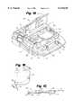
- FIG. 3Ais a plan view of a release liner of the present invention.
- FIG. 3Bis a sectional view of the release liner of FIG. 3A as taken along lines 3B--3B.
- FIG. 4Ais a plan view of a release liner of the present invention.
- FIG. 4Bis a sectional view of the release liner of FIG. 4A as taken along lines 4B--4B.
- FIG. 5is an enlarged plan view of a portion of a release liner of the present invention.
- AED 10for use with the present invention is shown generally at 10 in FIG. 1.
- AED 10is capable of monitoring a patient's cardiac rhythm, detecting cardiac defibrillation by comparing the monitored cardiac rhythm to nominal values, and delivering a series of therapeutic defibrillation shocks if defibrillation is detected.
- AED 10includes case 12 with carrying handle 14 and battery pack 16, which is removably disposed within a battery compartment (not shown) of case 12.
- Visual maintenance indicator 20 and data access door 22are located on the outside of case 12 to facilitate access by the operator.
- Case 12also defines panel 24 and electrode compartment 26 in a top portion thereof.
- Panel 24includes illuminable resume/rescue switch 18 and diagnostic display panel 25 with "Electrodes" indicator light 28. Panel 24 and electrode compartment 26 are enclosed by selectively closeable lid 27.
- Electrode compartment 26contains electrode connector 30 and electrode pouch 40, which hermetically encloses a pair of electrodes 50 in a sealed package. Electrodes 50 are removably connected to electrode connector 30 by leads 52. Electrodes 50 are attached to a patient prior to a rescue intervention procedure with AED 10.
- AED 10also includes a digital microprocessor-based electrical control system (not shown) for controlling overall operation of AED 10 and for delivering a defibrillation shock pulse through electrodes 50 via electrode connector 32 and leads 52.
- the electrical control systemfurther includes an impedance measuring circuit for testing the interconnection and operability of electrodes 50 to detect several errors. For example, if the conductive adhesive on electrodes 50 is too dry, or if electrodes 50 are not properly connected to electrode connector 32, a relatively high impedance (e.g., greater than about 20 ohms) will be present across electrode connector 32. However, when fresh electrodes 50 are properly packaged, the impedance across electrode connector 32 will be between about 2 and 10 ohms.
- an electrode self-testis conducted (e.g., daily, weekly, or upon opening or closing lid 27) in which the interconnection and operability of electrodes 50 are checked with the impedance measuring circuit. If electrodes 50 are missing or unplugged from connector 30, if electrodes 50 are damaged, or if the conductive hydrogel adhesive on electrodes 50 is too dry, the control system of AED 10 will illuminate "Electrodes" indicator light 28 on diagnostic display panel 25.
- electrode 50includes flexible adhesive-coated backing layer 53 (preferably a polymeric foam), and patient-engaging layer 54 which overlays backing layer 53.
- Patient-engaging layer 54is preferably a hydrogel material which has adhesive properties and which is electrically-conductive. Hydrogel adhesive of this type is commercially available from Lectec Corporation of Minnetonka, Minn. and Tyco International, Ltd. of Hamilton, Bermuda.
- Current-disbursing flexible conductive portion 56is preferably located between backing layer 53 and patient-engaging layer 54.
- Conductive portion 56as shown, need not be the same size as backing layer 53 and is preferably a homogeneous, solid, thinly deposited metallic substance, or a conductive ink.
- Insulated lead wires 52extend from electrode 50 and have an end electrically connected to conductive portion 56 via conductive terminal 58.
- an adhesive-coated border 57is formed by a portion of adhesive-coated backing layer 53. This border 57 extends about conductive portion 56 and patient-engaging layer 54.
- Electrode system 70includes electrode release liner 71 having conductive sheet 72 sandwiched between a pair of non-stick sheets 74A and 74B. Release liner 71 further includes side edges 76 and ends 78. Non-stick sheets 74A and 74B are preferably thin, flexible, members and include body portion 80, tabs 82A and 82B, respectively, and single aperture 86. Conductor sheet 72 is also a thin, flexible member which may include optional holes 92 and welding holes 94. When assembled, release liner 71 includes welding lines 96 that extend along side edges 76 with welding spots 98 formed between sheets 74A, 74B within holes 94 of conductive sheet 72.
- FIG. 2Bis a cross sectional view of FIG. 2A taken along lines 2B--2B.
- FIG. 2Billustrates conductive sheet 72 sandwiched between the pair of non-conductive sheets 74A and 74B.
- the thicknesses of sheets 72 and 74A, 74Bare exaggerated for illustrative purposes.
- sheets 74A, 74Bare so thin (e.g., 0.0029 inches) that the transition at aperture 86 between sheet 72 and sheets 74A, 74B is substantially flat and does not present a discontinuity or raised surface.
- aperture 86 of non-stick sheets 74A and 74Bdefine a region in 215 which conductive sheet 72 (with optional holes 92 formed therein) is the only layer forming that portion of the release liner 71.
- FIG. 2Billustrates welding lines 96, particularly including welding spots 98.
- welding spots 98are formed when non-stick sheet 74A is welded to non-stick sheet 74B in a region of conductive sheet 72 defining hole 94.
- This constructionyields a high weld strength since a stronger weld occurs between sheets 74A, 74B, made of the same first material (further discussed below) than when a weld is made with conductive sheet 72 (made of a different second material) extending between sheets 74A, 74B.
- FIG. 2Dis a cross-sectional view of release liner 71, taken along lines 2D--2D of FIG. 2A.
- conductive sheet 72is sandwiched between layers 74A and 74B with tab 82A of sheet 74A extending laterally outward from release liner 71 on one side edge 76 and tab 82B extending laterally outward from an opposite side edge 76 of release liner 71.
- Tabs 82A and 82Bfacilitate removal of electrodes 50 from release liner 71 by providing rescuers with convenient locations to grasp release liner 71 while peeling off electrodes 50.
- Electrode pad 50is shown in phantom as placed onto release liner 71. Electrode pad 50 has the features of electrode 50 shown in FIGS. 1B-1C, and includes conductive portion 56, adhesive border 57, conductive terminal 58, and electrical leads 52.
- FIG. 2Eis a cross-sectional view of electrode system 70 with a pair of electrodes 50 placed on release liner 71 within sealed package 100.
- the bottom electrode 50is shown with a portion broken away, and release liner 71 is simplified into a single thin sheet.
- Release liner 71is configured for placing electrode pad 50 on at least one, and preferably both sides of release liner 71. Electrode pad 50 is placed thereon so that patient-engaging layer 54 of electrode pad 50 is disposed over and in direct electrical contact with aperture 86 of release liner 71.
- This arrangementestablishes electrical connectivity, via conductive sheet 72, between conductive portion 56 of an electrode pad 50 on one side of the release liner 71 with conductive portion 56 of another electrode pad 50 on an opposite side of release liner 71.
- Optional holes 92 in conductor sheet 72further establish electrical connection between the conductive portions 56 of the electrode pads 50 on opposite sides of the release liner 71.
- Optional holes 92permit direct contact between the electrically conductive patient-engaging layer 54 of each of the electrode pads 50.
- adhesive border 57 of the electrode pad 50is disposed over non-stick body 80 of release liner sheets 74A, 74B without contacting conductive sheet 72 within aperture 86.
- Conductive sheet 72is preferably a polyethylene material loaded with carbon particles to render it conductive.
- Sheet 72is preferably a 4-mil plastic film which can be obtained from 3M Company of St. Paul, Minn., as Model 1704, or otherwise known as a VelostatTM Electrically-Conductive Film.
- the electrically-conductive polyethylene materialis widely known as polyethylene film used for static control, and rolls of this material may be readily purchased at low cost.
- suitable materials for conductive sheet 72include a foil made from a conductive metal such as nickel, stainless steel, tin, or aluminum.
- Non-stick sheets 74A and 74Bare preferably made of a polyester material also available from 3M Company of St. Paul, Minn., as Model 9956, Medical Release Liner. This polyester film is fluropolymer treated on one side to provide non-stick characteristics. Of course, other thermoplastic films could be used such as polyethylene and/or polypropylene materials treated with release agents such as silicon or fluropolymers. Sheets 74A, 74B are preferably transparent, although they can also be translucent or opaque.
- conductor sheet 72is secured between non-stick sheets 74A and 74B by welding along welding lines 96. Welding the sheets together permits construction of release liner 71 without the use of a transfer adhesive between non-stick sheets 74A, 74B and conductive sheet 72. This feature results in a significant cost savings due to the expensive nature of the transfer adhesive. This welding construction is accentuated by the use of holes 94 in conductive sheet 72 which permit direct welding between non-stick sheets 74A and 74B as highlighted in FIG. 2C.
- suitable welding techniquesinclude methods of using electromagnetic energy to weld, such as radio frequency energy, and methods of using friction to heat the material, such as ultrasonic welding.
- thermal welding techniquesare used to weld layered sheets 72, 74A and 74B together.
- an electrical heating elementis used to guarantee the heat required for welding.
- Patient-engaging layer 54 of electrode 50 shown in FIG. 1Cpreferably comprises a hydrogel material which is electrically conductive and also has adhesive properties, thereby permitting the patient-engaging layer 54 to form an electrical connection with the body and to adhere the electrode to the patient's skin.
- Adhesive-coated border portion 57preferably includes an acrylic adhesive to provide additional adhesion between electrodes 50 and the patient's skin.
- the aggressive acrylic adhesiveis permitted only to contact non-stick sheets 74A and 74B while the hydrogel material constituting patient-engaging layer 54 is permitted to contact conductive sheet 72 via aperture 86 of non-stick sheets 74A and 74B.
- optional holes 92 in conductive polyethylene sheet 72may be used to reduce electrical impedance between electrodes 50 on opposite sides of release liner 71.
- Optional holes 92must be small and few in number to avoid significantly increasing the peel force required to remove electrodes 50 from release liner 71.
- an electrode pad 50is placed on each side of release liner 71.
- Release liner 71covers patient-engaging layer 54 and adhesive border portion 57 of electrode pad 50 until ready for use. This liner prevents patient-engaging layer 54 and adhesive border portion 57 from collecting contaminants. Liner 71 also prevents adherence of the electrode pad to any other object.
- removably securing electrodes 50 on each side of release liner 71permits electrical conductivity between electrodes 50 for performing the electrode self-tests described above.
- Non-stick sheets 74A and 74Bpermit easy peeling removal of electrodes 50 from release liner 71 when required for application of electrodes 50 to a patient.
- electrode system 120 of the present inventionincludes release liner 121.
- Release liner 121includes conductive sheet 122 sandwiched between a pair of non-stick sheets 124A and 124B.
- Non-stick sheets 124A and 124Binclude patterned apertures 126 to expose conductive sheet 122 therethrough.
- a pattern of apertures 126form non-stick striping 134 between apertures 126.
- the patterned apertures 126are formed generally in the shape of a rectangle with a single corner recess 130. This arrangement results in a non-stick border 132.
- electrode 50can be placed over release liner 121 so that adhesive-coated border portion 57 of electrode pad 50 is disposed over non-stick border 132 of release liner 121 while conductive portion 56 of electrode pad 50 is disposed generally over patterned recesses 126, i.e., over the exposed portions of conductive sheet 122. Moreover, electrode terminal 58 is conveniently located over the non-conductive, rectangular-shaped patterned corner recess 130 of release liner 121.
- Non-stick striping 134is comprised of multiple stripes 134 that extend generally parallel to one another along a direction in which electrode pad 50 is peeled off release liner 121. Providing non-stick striping 134 in parallel along this direction reduces the peeling force necessary to remove electrode pad 50 from release liner 121.
- electrode system 150 of the present inventionincludes release liner 151, having conductive sheet 152 sandwiched between a pair of non-stick sheets 154A and 154B.
- Non-stick sheets 154A and 154Binclude patterned holes 156 which permit exposure of conductive sheet 152 therethrough. Patterned holes 156 are arranged generally in the form of a rectangle comprised of multiple triangular sections having at least one of their vertices opposed to each other. The arrangement of patterned holes 156 creates non-stick striping 164 as well as corner, non-stick rectangular-shaped portions 160. The remainder of non-stick sheets 154A and 154B define non-stick border 162.
- conductive portion 56 of electrode pad 50is disposed over conductive sheet portion 152 exposed through patterned holes 156 of release liner 151.
- adhesive-coated border portion 57 of electrode pad 50is disposed over non-stick border 162. Corner recesses 160 are shaped to accommodate electrode pad terminal 58.
- conductive sheets 122 and 152do not include optional holes, and therefore do not permit direct contact of hydrogel materials (on patient-engaging layer 54 on electrode pads 50) on opposite sides of release liner 121 or 151 therethrough as in the embodiment of FIG. 2A. Accordingly, the embodiment FIGS. 3A and 4A prevents the hydrogel material on layer 54 on one electrode 50 from adhering strongly to the hydrogel material on layer 54 on the other electrode 50. Electrical conductivity between electrodes is still maintained since sheets 122 or 152 are electrically conductive.
- the lack of optional holes 92reduces the peeling force required to remove electrodes 50 from release liner 121 or 151. However, the lack of optional holes 92 also increases the electrical impedance between electrodes 50.
- Both the embodiments of FIG. 3A and FIG. 4Ahave a similar construction in that both include conductive sheet (122 or 152) formed of a polyethylene film loaded with carbon particles to provide its conductive characteristics.
- Non-stick sheets 124A, 124B and 154A, 154Bare preferably a polyester film treated on an outer side of the non-stick sheet with a release agent such as fluropolymer or silicone.
- a transfer adhesiveis placed on an inner side of the sheet (124A, 124B and 154A, 154B) for bonding the adhesive side of each non-stick sheet to a conductive sheet (122 or 152).
- a suitable transfer adhesiveis commercially available from 3M Company of St. Paul, Minn., identified as model 1524.
- non-stick sheets 124A, 124B and 154A, 154Bmay be made of a non-thermoplastic material such as paper treated with a release agent.
- Non-stick sheets 124A, 124B and 154A, 154Bmay also be made of thermoplastic materials such as polyester, polyethylene or polypropylene.
- the electrode system of the present inventioncan be used for many other medical procedures such as EKG, EEG, EMG, ESU, TENS etc.
- the electrical impedancecan be further reduced by placing holes in the exposed portion of conductive sheet (72, 122 or 152), to allow direct contact of the hydrogel between the electrodes. This arrangement also increases the peel force required to remove the electrodes from the release liner.
- release liner(71, 121 or 151) facilitates placement of important, instruction labeling in a manner that does not interfere with the non-stick/electrically-conductive interface between the electrode pads and the release liner.
- release liner 71includes instruction label 200 secured thereon either on inner surface of transparent sheet 74A or on the surface of sheet 72.
- label 200When an electrode pad 50 is placed on liner 71, label 200 will be hidden. However, when electrode pad 50 is removed for application to a patient, label 200 becomes visible to provide the operator with a timely reminder.
- Instruction label 200reminds the operator to remove both electrodes 50 from the release liner 71. This instruction is intended to prevent application of an electrode to the patient's chest while release liner 71 is still adhered to it. While seemingly simplistic, the multiple sheet construction which facilitates this labeling is significant since labeling on an outer surface of a single sheet release liner can interfere with the non-stick/electrically-conductive interface between the electrode pads and the release liner.
- the combination of multi-sheet construction and the location of instruction labeling on the release lineris also significant since the labeling provides an instructive reminder of the exact point in time when it is needed.
- the operator of an AEDwill most likely be a first responder, such as a firefighter or police officer. These operators typically have little medical background and do not routinely perform defibrillation. Clear and timely instructions are critical when performing a rescue in a high-stress, emergency situation.
- the information in label 200also can be printed directly onto the inner surface of transparent sheet 74A or on the surface of sheet 72.
Landscapes
- Health & Medical Sciences (AREA)
- Engineering & Computer Science (AREA)
- Biomedical Technology (AREA)
- Nuclear Medicine, Radiotherapy & Molecular Imaging (AREA)
- Radiology & Medical Imaging (AREA)
- Life Sciences & Earth Sciences (AREA)
- Animal Behavior & Ethology (AREA)
- General Health & Medical Sciences (AREA)
- Public Health (AREA)
- Veterinary Medicine (AREA)
- Electrotherapy Devices (AREA)
Abstract
Description
Claims (29)
Priority Applications (1)
| Application Number | Priority Date | Filing Date | Title |
|---|---|---|---|
| US09/152,565US6115638A (en) | 1998-05-04 | 1998-09-14 | Medical electrode with conductive release liner |
Applications Claiming Priority (2)
| Application Number | Priority Date | Filing Date | Title |
|---|---|---|---|
| US8400998P | 1998-05-04 | 1998-05-04 | |
| US09/152,565US6115638A (en) | 1998-05-04 | 1998-09-14 | Medical electrode with conductive release liner |
Publications (1)
| Publication Number | Publication Date |
|---|---|
| US6115638Atrue US6115638A (en) | 2000-09-05 |
Family
ID=26770332
Family Applications (1)
| Application Number | Title | Priority Date | Filing Date |
|---|---|---|---|
| US09/152,565Expired - LifetimeUS6115638A (en) | 1998-05-04 | 1998-09-14 | Medical electrode with conductive release liner |
Country Status (1)
| Country | Link |
|---|---|
| US (1) | US6115638A (en) |
Cited By (86)
| Publication number | Priority date | Publication date | Assignee | Title |
|---|---|---|---|---|
| US20030171797A1 (en)* | 2002-03-08 | 2003-09-11 | Nova Richard C. | Therapy and monitoring electrodes with patient accommodating features |
| US20030216787A1 (en)* | 2002-05-08 | 2003-11-20 | Michael Worden | Method of applying electrical signals to a patient and automatic wearable external defibrillator |
| US6675051B2 (en)* | 2000-12-22 | 2004-01-06 | Koninklijke Philips Electronics N.V. | See-through electrode-pad package and method for using a storage system that includes the package |
| US6694193B2 (en) | 2001-09-14 | 2004-02-17 | Koninklijke Philips Electronics N.V. | Medical electrode and release liner configurations facilitating packaged electrode characterization |
| US20050261749A1 (en)* | 2001-10-01 | 2005-11-24 | Transoma Medical, Inc. | System and method for telemetry of analog and digital data |
| US20050283219A1 (en)* | 2004-06-16 | 2005-12-22 | O'connor Rose M | Packaging for medical pads and electrodes |
| US7027877B2 (en) | 2001-08-23 | 2006-04-11 | Zoll Medical Corporation | Method of applying defibrilator electrode pad with folded release sheet |
| US7069074B2 (en) | 2001-11-07 | 2006-06-27 | Medtronic Emergency Response Systems, Inc. | Easy-to-use electrode and package |
| US20060142806A1 (en)* | 2004-12-27 | 2006-06-29 | Koninklijke Philips Electronics N.V. | Method and article for storing an automatic external defibrillator for use without a prescription |
| EP1365973A4 (en)* | 2001-02-27 | 2007-01-24 | Koninkl Philips Electronics Nv | Method and package for increasing electrode shelf life |
| US7171265B2 (en) | 1998-07-31 | 2007-01-30 | Harbinger Medical, Inc. | Apparatus and method for detecting lead adequacy and quality |
| WO2008059395A1 (en)* | 2006-11-13 | 2008-05-22 | Koninklijke Philips Electronics, N.V. | Halibut release liner for a defibrillator electrode pad |
| US20080200793A1 (en)* | 2007-02-15 | 2008-08-21 | Tanita Corporation | Cover sheet for a body measuring apparatus and an automatic sheet dispenser therefor |
| US20080221631A1 (en)* | 2007-03-07 | 2008-09-11 | Conduct Prosecution | External Defibrillators,Transcutaneous Electrodes for Same, and Methods of Use |
| US20090029332A1 (en)* | 2004-02-10 | 2009-01-29 | Koninklijke Philips Electronics, N.V. | External defibrillator training apparatus and method |
| US20090076582A1 (en)* | 2004-07-28 | 2009-03-19 | Nihon Kohden Corporation | Packaged biomedical electrode unit and method of inspecting quality thereof |
| WO2009077132A3 (en)* | 2007-12-14 | 2010-03-18 | Erbe Elektromedizin Gmbh | Neutral electrode detection |
| US20100075532A1 (en)* | 2008-09-25 | 2010-03-25 | Tyco Healthcare Group Lp | Fluorescent Marker for Detecting Gel or Lack of Gel |
| US20100072060A1 (en)* | 2008-09-25 | 2010-03-25 | Tyco Healthcare Group Lp | Biomedical Electrode and Method of Formation Thereof |
| US20100076294A1 (en)* | 2008-09-25 | 2010-03-25 | Tyco Healthcare Group Lp | System and Method of Prepping Skin Prior to Electrode Application |
| US20100081913A1 (en)* | 2006-12-07 | 2010-04-01 | Koninklijke Philips Electronics N.V. | Handheld, repositionable ecg detector |
| US20110071611A1 (en)* | 2007-03-08 | 2011-03-24 | Pisit Khuon | Defibrillation Electrodes |
| US20110257695A1 (en)* | 2006-11-13 | 2011-10-20 | Koninklijke Philips Electronics N.V. | Pinch case for defibrillator electrode pads and release liner |
| WO2013010179A1 (en)* | 2011-07-14 | 2013-01-17 | Verathon Inc. | Releasable liner for sensor device |
| USD675739S1 (en) | 2011-12-07 | 2013-02-05 | Cardiac Science Corporation | Automated external defibrillator electrode pad |
| US8428751B2 (en) | 2010-03-18 | 2013-04-23 | Covidien Lp | Electrode delivery system |
| US20130115465A1 (en)* | 2010-07-02 | 2013-05-09 | Huhtamaki Films Germany Gmbh & Co. Kg | Release film with long-term antistatic effect |
| US8515522B2 (en) | 2010-05-25 | 2013-08-20 | Neurowave Systems Inc. | Electrode kit for easy and fast deployment in electroencephalogram acquisition and monitoring applications |
| CN101534899B (en)* | 2006-11-13 | 2013-11-20 | 皇家飞利浦电子股份有限公司 | Housings for defibrillator paddles and release liners |
| US8613709B2 (en) | 2010-10-08 | 2013-12-24 | Cardiac Science Corporation | Ambulatory electrocardiographic monitor for providing ease of use in women |
| US8613708B2 (en) | 2010-10-08 | 2013-12-24 | Cardiac Science Corporation | Ambulatory electrocardiographic monitor with jumpered sensing electrode |
| US8626277B2 (en) | 2010-10-08 | 2014-01-07 | Cardiac Science Corporation | Computer-implemented electrocardiographic data processor with time stamp correlation |
| US8798743B1 (en)* | 2013-03-04 | 2014-08-05 | Zoll Medical Corporation | Self-contained cardiac response unit |
| USD717955S1 (en) | 2013-11-07 | 2014-11-18 | Bardy Diagnostics, Inc. | Electrocardiography monitor |
| US9037477B2 (en) | 2010-10-08 | 2015-05-19 | Cardiac Science Corporation | Computer-implemented system and method for evaluating ambulatory electrocardiographic monitoring of cardiac rhythm disorders |
| US9072885B2 (en) | 2012-09-27 | 2015-07-07 | Covidien Lp | Systems for hydrating defibrillation electrodes |
| AT515632A1 (en)* | 2014-03-27 | 2015-10-15 | Leonh Lang | Electrode set, especially for a defibrillator |
| USD744659S1 (en) | 2013-11-07 | 2015-12-01 | Bardy Diagnostics, Inc. | Extended wear electrode patch |
| US9345414B1 (en) | 2013-09-25 | 2016-05-24 | Bardy Diagnostics, Inc. | Method for providing dynamic gain over electrocardiographic data with the aid of a digital computer |
| US9364155B2 (en) | 2013-09-25 | 2016-06-14 | Bardy Diagnostics, Inc. | Self-contained personal air flow sensing monitor |
| US9408545B2 (en) | 2013-09-25 | 2016-08-09 | Bardy Diagnostics, Inc. | Method for efficiently encoding and compressing ECG data optimized for use in an ambulatory ECG monitor |
| US9408551B2 (en) | 2013-11-14 | 2016-08-09 | Bardy Diagnostics, Inc. | System and method for facilitating diagnosis of cardiac rhythm disorders with the aid of a digital computer |
| US9433367B2 (en) | 2013-09-25 | 2016-09-06 | Bardy Diagnostics, Inc. | Remote interfacing of extended wear electrocardiography and physiological sensor monitor |
| US9433380B1 (en) | 2013-09-25 | 2016-09-06 | Bardy Diagnostics, Inc. | Extended wear electrocardiography patch |
| USD766447S1 (en) | 2015-09-10 | 2016-09-13 | Bardy Diagnostics, Inc. | Extended wear electrode patch |
| US9504423B1 (en) | 2015-10-05 | 2016-11-29 | Bardy Diagnostics, Inc. | Method for addressing medical conditions through a wearable health monitor with the aid of a digital computer |
| US9545204B2 (en) | 2013-09-25 | 2017-01-17 | Bardy Diagnostics, Inc. | Extended wear electrocardiography patch |
| US9615790B2 (en) | 2011-07-14 | 2017-04-11 | Verathon Inc. | Sensor device with flexible joints |
| US9615763B2 (en) | 2013-09-25 | 2017-04-11 | Bardy Diagnostics, Inc. | Ambulatory electrocardiography monitor recorder optimized for capturing low amplitude cardiac action potential propagation |
| US9619660B1 (en) | 2013-09-25 | 2017-04-11 | Bardy Diagnostics, Inc. | Computer-implemented system for secure physiological data collection and processing |
| US9655537B2 (en) | 2013-09-25 | 2017-05-23 | Bardy Diagnostics, Inc. | Wearable electrocardiography and physiology monitoring ensemble |
| US9655538B2 (en) | 2013-09-25 | 2017-05-23 | Bardy Diagnostics, Inc. | Self-authenticating electrocardiography monitoring circuit |
| US9700227B2 (en) | 2013-09-25 | 2017-07-11 | Bardy Diagnostics, Inc. | Ambulatory electrocardiography monitoring patch optimized for capturing low amplitude cardiac action potential propagation |
| US9717433B2 (en) | 2013-09-25 | 2017-08-01 | Bardy Diagnostics, Inc. | Ambulatory electrocardiography monitoring patch optimized for capturing low amplitude cardiac action potential propagation |
| USD793566S1 (en) | 2015-09-10 | 2017-08-01 | Bardy Diagnostics, Inc. | Extended wear electrode patch |
| US9717432B2 (en) | 2013-09-25 | 2017-08-01 | Bardy Diagnostics, Inc. | Extended wear electrocardiography patch using interlaced wire electrodes |
| US9737224B2 (en) | 2013-09-25 | 2017-08-22 | Bardy Diagnostics, Inc. | Event alerting through actigraphy embedded within electrocardiographic data |
| US9775536B2 (en) | 2013-09-25 | 2017-10-03 | Bardy Diagnostics, Inc. | Method for constructing a stress-pliant physiological electrode assembly |
| USD801528S1 (en) | 2013-11-07 | 2017-10-31 | Bardy Diagnostics, Inc. | Electrocardiography monitor |
| US20170332967A1 (en)* | 2014-11-17 | 2017-11-23 | Sekisui Plastics Co., Ltd. | Pad for electrodes |
| USD831833S1 (en) | 2013-11-07 | 2018-10-23 | Bardy Diagnostics, Inc. | Extended wear electrode patch |
| US10165946B2 (en) | 2013-09-25 | 2019-01-01 | Bardy Diagnostics, Inc. | Computer-implemented system and method for providing a personal mobile device-triggered medical intervention |
| US10251576B2 (en) | 2013-09-25 | 2019-04-09 | Bardy Diagnostics, Inc. | System and method for ECG data classification for use in facilitating diagnosis of cardiac rhythm disorders with the aid of a digital computer |
| US10433751B2 (en) | 2013-09-25 | 2019-10-08 | Bardy Diagnostics, Inc. | System and method for facilitating a cardiac rhythm disorder diagnosis based on subcutaneous cardiac monitoring data |
| US10433748B2 (en) | 2013-09-25 | 2019-10-08 | Bardy Diagnostics, Inc. | Extended wear electrocardiography and physiological sensor monitor |
| US10463269B2 (en) | 2013-09-25 | 2019-11-05 | Bardy Diagnostics, Inc. | System and method for machine-learning-based atrial fibrillation detection |
| US10624551B2 (en) | 2013-09-25 | 2020-04-21 | Bardy Diagnostics, Inc. | Insertable cardiac monitor for use in performing long term electrocardiographic monitoring |
| US10667711B1 (en) | 2013-09-25 | 2020-06-02 | Bardy Diagnostics, Inc. | Contact-activated extended wear electrocardiography and physiological sensor monitor recorder |
| USD892340S1 (en) | 2013-11-07 | 2020-08-04 | Bardy Diagnostics, Inc. | Extended wear electrode patch |
| US10736529B2 (en) | 2013-09-25 | 2020-08-11 | Bardy Diagnostics, Inc. | Subcutaneous insertable electrocardiography monitor |
| US10736531B2 (en) | 2013-09-25 | 2020-08-11 | Bardy Diagnostics, Inc. | Subcutaneous insertable cardiac monitor optimized for long term, low amplitude electrocardiographic data collection |
| US10799137B2 (en) | 2013-09-25 | 2020-10-13 | Bardy Diagnostics, Inc. | System and method for facilitating a cardiac rhythm disorder diagnosis with the aid of a digital computer |
| US10806360B2 (en) | 2013-09-25 | 2020-10-20 | Bardy Diagnostics, Inc. | Extended wear ambulatory electrocardiography and physiological sensor monitor |
| US10820801B2 (en) | 2013-09-25 | 2020-11-03 | Bardy Diagnostics, Inc. | Electrocardiography monitor configured for self-optimizing ECG data compression |
| US10888239B2 (en) | 2013-09-25 | 2021-01-12 | Bardy Diagnostics, Inc. | Remote interfacing electrocardiography patch |
| USD926323S1 (en) | 2020-03-30 | 2021-07-27 | Zoll Medical Corporation | Automated external defibrillator electrode pad |
| US11096579B2 (en) | 2019-07-03 | 2021-08-24 | Bardy Diagnostics, Inc. | System and method for remote ECG data streaming in real-time |
| US11116451B2 (en) | 2019-07-03 | 2021-09-14 | Bardy Diagnostics, Inc. | Subcutaneous P-wave centric insertable cardiac monitor with energy harvesting capabilities |
| US11213237B2 (en) | 2013-09-25 | 2022-01-04 | Bardy Diagnostics, Inc. | System and method for secure cloud-based physiological data processing and delivery |
| US11324441B2 (en) | 2013-09-25 | 2022-05-10 | Bardy Diagnostics, Inc. | Electrocardiography and respiratory monitor |
| US20230084585A1 (en)* | 2021-09-14 | 2023-03-16 | Stryker Corporation | Electrode assembly, systems, and methods of use thereof |
| US11678830B2 (en) | 2017-12-05 | 2023-06-20 | Bardy Diagnostics, Inc. | Noise-separating cardiac monitor |
| US11696681B2 (en) | 2019-07-03 | 2023-07-11 | Bardy Diagnostics Inc. | Configurable hardware platform for physiological monitoring of a living body |
| US11723575B2 (en) | 2013-09-25 | 2023-08-15 | Bardy Diagnostics, Inc. | Electrocardiography patch |
| USD1084346S1 (en) | 2022-07-28 | 2025-07-15 | Zoll Medical Corporation | Chest compression sensor |
| USD1084345S1 (en) | 2022-07-28 | 2025-07-15 | Zoll Medical Corporation | Chest compression sensor |
Citations (61)
| Publication number | Priority date | Publication date | Assignee | Title |
|---|---|---|---|---|
| US2590876A (en)* | 1947-12-20 | 1952-04-01 | Landauer Fred | Electrode for electrotherapeutic treatments |
| US3602216A (en)* | 1969-09-16 | 1971-08-31 | United Aircraft Corp | Paste dispensing body electrode |
| US3685645A (en)* | 1970-08-17 | 1972-08-22 | Physio Control Corp | Defibrillation electrode pad and package therefor |
| US3698549A (en)* | 1971-03-10 | 1972-10-17 | Jacob A Glassman | Packages for small articles |
| US3701346A (en)* | 1971-01-04 | 1972-10-31 | Bionetics Inc | Medical electrode |
| US3805769A (en)* | 1971-08-27 | 1974-04-23 | R Sessions | Disposable electrode |
| US3834373A (en)* | 1972-02-24 | 1974-09-10 | T Sato | Silver, silver chloride electrodes |
| US3868946A (en)* | 1973-07-13 | 1975-03-04 | James S Hurley | Medical electrode |
| US3961623A (en)* | 1975-01-17 | 1976-06-08 | Medical Research Laboratories, Inc. | Method of using a disposable electrode pad |
| USD243717S (en) | 1975-08-18 | 1977-03-15 | Physio Control Corporation | Physiological monitoring device housing |
| US4034854A (en)* | 1976-07-16 | 1977-07-12 | M I Systems, Inc. | Electrode package |
| US4040412A (en)* | 1974-08-09 | 1977-08-09 | Sato Takuya R | Bioelectrodes |
| US4082086A (en)* | 1976-12-13 | 1978-04-04 | M I Systems, Inc. | Ecg monitoring pad |
| US4092985A (en)* | 1974-11-25 | 1978-06-06 | John George Kaufman | Body electrode for electro-medical use |
| US4176746A (en)* | 1978-07-10 | 1979-12-04 | Arvey Corporation | Gusset pouch with integral seal support and method of making same |
| FR2483215A3 (en)* | 1980-06-02 | 1981-12-04 | Medtronic Inc | TEMPORARY PACKAGING FOR AN ELECTRICAL COMPONENT |
| US4353373A (en)* | 1980-04-17 | 1982-10-12 | Ferris Manufacturing Corp. | EKG Electrode and package |
| US4362165A (en)* | 1980-01-08 | 1982-12-07 | Ipco Corporation | Stable gel electrode |
| US4365634A (en)* | 1979-12-06 | 1982-12-28 | C. R. Bard, Inc. | Medical electrode construction |
| US4423732A (en)* | 1980-09-26 | 1984-01-03 | Cordis Corporation | Sterile connector system for packaged pacer |
| US4439810A (en)* | 1981-09-10 | 1984-03-27 | Marcon Electronics Co., Ltd. | Electric capacitor with enclosure structure consisting of plastic laminated film |
| US4487313A (en)* | 1981-02-20 | 1984-12-11 | William C. Heller, Jr. | Enclosed moist pad assembly with removable cover |
| US4494552A (en)* | 1980-08-08 | 1985-01-22 | R2 Corporation | Physiological monitoring electrode system |
| US4522211A (en)* | 1979-12-06 | 1985-06-11 | C. R. Bard, Inc. | Medical electrode construction |
| US4543958A (en)* | 1979-04-30 | 1985-10-01 | Ndm Corporation | Medical electrode assembly |
| US4653501A (en)* | 1986-04-17 | 1987-03-31 | Baxter Travenol Laboratories, Inc. | Medical electrode with reusable conductor |
| US4777954A (en)* | 1986-06-30 | 1988-10-18 | Nepera Inc. | Conductive adhesive medical electrode assemblies |
| US4779630A (en)* | 1987-09-18 | 1988-10-25 | Katecho, Inc. | Defibrillator pad assembly and method for using same |
| US4798208A (en)* | 1987-12-09 | 1989-01-17 | Faasse Jr Adrian L | Diagnostic electrode |
| US4838273A (en)* | 1979-04-30 | 1989-06-13 | Baxter International Inc. | Medical electrode |
| US4852571A (en)* | 1987-09-03 | 1989-08-01 | Marquette Electronics | Disposable biopotential electrode |
| US4978007A (en)* | 1989-05-10 | 1990-12-18 | Minnesota Mining And Manufacturing Company | Packaging curable materials |
| US4979517A (en)* | 1988-02-01 | 1990-12-25 | Physio-Control Corporation | Disposable stimulation electrode with long shelf life and improved current density profile |
| US5123423A (en)* | 1989-12-26 | 1992-06-23 | Kas Products, Inc. | Defibrillator pad assembly and method for using same |
| US5148805A (en)* | 1991-02-11 | 1992-09-22 | Kas Products, Inc. | Defibrillator pad system and method for using same |
| US5150708A (en)* | 1990-12-03 | 1992-09-29 | Spacelabs, Inc. | Tabbed defibrillator electrode pad |
| US5161539A (en)* | 1991-05-09 | 1992-11-10 | Physio-Control | Method and apparatus for performing mapping-type analysis including use of limited electrode sets |
| US5184620A (en)* | 1991-12-26 | 1993-02-09 | Marquette Electronics, Inc. | Method of using a multiple electrode pad assembly |
| US5191886A (en)* | 1991-04-18 | 1993-03-09 | Physio-Control Corporation | Multiple electrode strip |
| US5203330A (en)* | 1991-02-26 | 1993-04-20 | Vickers Plc | Disposable electrodes for electromyography (EMG) and nerve conduction velocity (NCV) and kit containing same |
| US5255677A (en)* | 1991-02-26 | 1993-10-26 | Vickers Plc | Disposable electrodes for electromyography (EMG) and nerve conduction velocity (NCV) and kit containing same |
| US5275572A (en)* | 1990-01-09 | 1994-01-04 | Physio-Control Corporation | Training electrode foil used in defibrillator/monitor instruction and method of instruction |
| US5309909A (en)* | 1992-05-22 | 1994-05-10 | Physio-Control Corporation | Combined skin preparation and monitoring electrode |
| US5330526A (en)* | 1992-05-01 | 1994-07-19 | Zmd Corporation | Combined defibrillation and pacing electrode |
| US5341806A (en)* | 1991-04-18 | 1994-08-30 | Physio-Control Corporation | Multiple electrode strip |
| US5354321A (en)* | 1990-10-10 | 1994-10-11 | Mario Berger | Patch arrangement for galvanic treatment |
| WO1994027674A1 (en)* | 1993-05-18 | 1994-12-08 | Heartstream, Inc. | Defibrillator with self-test features |
| US5402884A (en)* | 1992-09-24 | 1995-04-04 | Surviva Link Corporation | Medical electrode packaging technology |
| US5431688A (en)* | 1990-06-12 | 1995-07-11 | Zmd Corporation | Method and apparatus for transcutaneous electrical cardiac pacing |
| US5456710A (en)* | 1994-06-30 | 1995-10-10 | Physio-Control Corporation | Vented electrode |
| US5462157A (en)* | 1993-10-28 | 1995-10-31 | Zmd Corporation | Electrode package |
| US5466217A (en)* | 1992-06-02 | 1995-11-14 | Alza Corporation | Iontophoretic drug delivery apparatus |
| US5466244A (en)* | 1993-05-18 | 1995-11-14 | Heartstream, Inc. | Defibrillator electrode system |
| US5520683A (en)* | 1994-05-16 | 1996-05-28 | Physiometrix, Inc. | Medical electrode and method |
| US5562710A (en)* | 1993-04-06 | 1996-10-08 | Hewlett-Packard Company | Defibrillator patient connection system with automatic identification |
| US5591213A (en)* | 1993-05-18 | 1997-01-07 | Heartstream, Inc. | Defibrillator system condition indictator |
| US5645571A (en)* | 1995-08-01 | 1997-07-08 | Survivalink Corporation | Automated external defibrillator with lid activated self-test system |
| US5650750A (en)* | 1995-03-03 | 1997-07-22 | Heartstream, Inc. | Common mode signal and circuit fault detection in differential signal detectors |
| US5697955A (en)* | 1996-05-10 | 1997-12-16 | Survivalink Corporation | Defibrillator electrodes and date code detector circuit |
| US5817151A (en)* | 1996-06-04 | 1998-10-06 | Survivalink Corporation | Circuit detectable packaged medical electrodes |
| US5974344A (en)* | 1998-03-02 | 1999-10-26 | Shoemaker, Ii; Charles | Wound care electrode |
- 1998
- 1998-09-14USUS09/152,565patent/US6115638A/ennot_activeExpired - Lifetime
Patent Citations (65)
| Publication number | Priority date | Publication date | Assignee | Title |
|---|---|---|---|---|
| US2590876A (en)* | 1947-12-20 | 1952-04-01 | Landauer Fred | Electrode for electrotherapeutic treatments |
| US3602216A (en)* | 1969-09-16 | 1971-08-31 | United Aircraft Corp | Paste dispensing body electrode |
| US3685645A (en)* | 1970-08-17 | 1972-08-22 | Physio Control Corp | Defibrillation electrode pad and package therefor |
| US3701346A (en)* | 1971-01-04 | 1972-10-31 | Bionetics Inc | Medical electrode |
| US3698549A (en)* | 1971-03-10 | 1972-10-17 | Jacob A Glassman | Packages for small articles |
| US3805769A (en)* | 1971-08-27 | 1974-04-23 | R Sessions | Disposable electrode |
| US3834373A (en)* | 1972-02-24 | 1974-09-10 | T Sato | Silver, silver chloride electrodes |
| US3868946A (en)* | 1973-07-13 | 1975-03-04 | James S Hurley | Medical electrode |
| US4040412A (en)* | 1974-08-09 | 1977-08-09 | Sato Takuya R | Bioelectrodes |
| US4092985A (en)* | 1974-11-25 | 1978-06-06 | John George Kaufman | Body electrode for electro-medical use |
| US3961623A (en)* | 1975-01-17 | 1976-06-08 | Medical Research Laboratories, Inc. | Method of using a disposable electrode pad |
| USD243717S (en) | 1975-08-18 | 1977-03-15 | Physio Control Corporation | Physiological monitoring device housing |
| US4034854A (en)* | 1976-07-16 | 1977-07-12 | M I Systems, Inc. | Electrode package |
| US4082086A (en)* | 1976-12-13 | 1978-04-04 | M I Systems, Inc. | Ecg monitoring pad |
| US4176746A (en)* | 1978-07-10 | 1979-12-04 | Arvey Corporation | Gusset pouch with integral seal support and method of making same |
| US4543958A (en)* | 1979-04-30 | 1985-10-01 | Ndm Corporation | Medical electrode assembly |
| US4838273A (en)* | 1979-04-30 | 1989-06-13 | Baxter International Inc. | Medical electrode |
| US4522211A (en)* | 1979-12-06 | 1985-06-11 | C. R. Bard, Inc. | Medical electrode construction |
| US4365634A (en)* | 1979-12-06 | 1982-12-28 | C. R. Bard, Inc. | Medical electrode construction |
| US4362165A (en)* | 1980-01-08 | 1982-12-07 | Ipco Corporation | Stable gel electrode |
| US4353373A (en)* | 1980-04-17 | 1982-10-12 | Ferris Manufacturing Corp. | EKG Electrode and package |
| FR2483215A3 (en)* | 1980-06-02 | 1981-12-04 | Medtronic Inc | TEMPORARY PACKAGING FOR AN ELECTRICAL COMPONENT |
| US4494552A (en)* | 1980-08-08 | 1985-01-22 | R2 Corporation | Physiological monitoring electrode system |
| US4423732A (en)* | 1980-09-26 | 1984-01-03 | Cordis Corporation | Sterile connector system for packaged pacer |
| US4487313A (en)* | 1981-02-20 | 1984-12-11 | William C. Heller, Jr. | Enclosed moist pad assembly with removable cover |
| US4439810A (en)* | 1981-09-10 | 1984-03-27 | Marcon Electronics Co., Ltd. | Electric capacitor with enclosure structure consisting of plastic laminated film |
| US4653501A (en)* | 1986-04-17 | 1987-03-31 | Baxter Travenol Laboratories, Inc. | Medical electrode with reusable conductor |
| US4777954A (en)* | 1986-06-30 | 1988-10-18 | Nepera Inc. | Conductive adhesive medical electrode assemblies |
| US4852571A (en)* | 1987-09-03 | 1989-08-01 | Marquette Electronics | Disposable biopotential electrode |
| US4779630A (en)* | 1987-09-18 | 1988-10-25 | Katecho, Inc. | Defibrillator pad assembly and method for using same |
| US4798208A (en)* | 1987-12-09 | 1989-01-17 | Faasse Jr Adrian L | Diagnostic electrode |
| US4979517A (en)* | 1988-02-01 | 1990-12-25 | Physio-Control Corporation | Disposable stimulation electrode with long shelf life and improved current density profile |
| US4978007A (en)* | 1989-05-10 | 1990-12-18 | Minnesota Mining And Manufacturing Company | Packaging curable materials |
| US5123423A (en)* | 1989-12-26 | 1992-06-23 | Kas Products, Inc. | Defibrillator pad assembly and method for using same |
| US5275572A (en)* | 1990-01-09 | 1994-01-04 | Physio-Control Corporation | Training electrode foil used in defibrillator/monitor instruction and method of instruction |
| US5431688A (en)* | 1990-06-12 | 1995-07-11 | Zmd Corporation | Method and apparatus for transcutaneous electrical cardiac pacing |
| US5354321A (en)* | 1990-10-10 | 1994-10-11 | Mario Berger | Patch arrangement for galvanic treatment |
| US5150708A (en)* | 1990-12-03 | 1992-09-29 | Spacelabs, Inc. | Tabbed defibrillator electrode pad |
| US5148805A (en)* | 1991-02-11 | 1992-09-22 | Kas Products, Inc. | Defibrillator pad system and method for using same |
| US5203330A (en)* | 1991-02-26 | 1993-04-20 | Vickers Plc | Disposable electrodes for electromyography (EMG) and nerve conduction velocity (NCV) and kit containing same |
| US5255677A (en)* | 1991-02-26 | 1993-10-26 | Vickers Plc | Disposable electrodes for electromyography (EMG) and nerve conduction velocity (NCV) and kit containing same |
| US5191886A (en)* | 1991-04-18 | 1993-03-09 | Physio-Control Corporation | Multiple electrode strip |
| US5341806A (en)* | 1991-04-18 | 1994-08-30 | Physio-Control Corporation | Multiple electrode strip |
| US5161539A (en)* | 1991-05-09 | 1992-11-10 | Physio-Control | Method and apparatus for performing mapping-type analysis including use of limited electrode sets |
| US5184620A (en)* | 1991-12-26 | 1993-02-09 | Marquette Electronics, Inc. | Method of using a multiple electrode pad assembly |
| US5330526A (en)* | 1992-05-01 | 1994-07-19 | Zmd Corporation | Combined defibrillation and pacing electrode |
| US5309909A (en)* | 1992-05-22 | 1994-05-10 | Physio-Control Corporation | Combined skin preparation and monitoring electrode |
| US5466217A (en)* | 1992-06-02 | 1995-11-14 | Alza Corporation | Iontophoretic drug delivery apparatus |
| US5850920A (en)* | 1992-09-24 | 1998-12-22 | Survivalink Corporation | Medical electrode packaging technology |
| US5402884A (en)* | 1992-09-24 | 1995-04-04 | Surviva Link Corporation | Medical electrode packaging technology |
| US5579919A (en)* | 1992-09-24 | 1996-12-03 | Survivalink Corporation | Medical electrode packaging technology |
| US5562710A (en)* | 1993-04-06 | 1996-10-08 | Hewlett-Packard Company | Defibrillator patient connection system with automatic identification |
| US5617853A (en)* | 1993-05-18 | 1997-04-08 | Heartstream, Inc. | Defibrillator electrode system using a flexible substrate and having electrode test features |
| US5466244A (en)* | 1993-05-18 | 1995-11-14 | Heartstream, Inc. | Defibrillator electrode system |
| US5591213A (en)* | 1993-05-18 | 1997-01-07 | Heartstream, Inc. | Defibrillator system condition indictator |
| WO1994027674A1 (en)* | 1993-05-18 | 1994-12-08 | Heartstream, Inc. | Defibrillator with self-test features |
| US5462157A (en)* | 1993-10-28 | 1995-10-31 | Zmd Corporation | Electrode package |
| US5520683A (en)* | 1994-05-16 | 1996-05-28 | Physiometrix, Inc. | Medical electrode and method |
| US5456710A (en)* | 1994-06-30 | 1995-10-10 | Physio-Control Corporation | Vented electrode |
| US5650750A (en)* | 1995-03-03 | 1997-07-22 | Heartstream, Inc. | Common mode signal and circuit fault detection in differential signal detectors |
| US5645571A (en)* | 1995-08-01 | 1997-07-08 | Survivalink Corporation | Automated external defibrillator with lid activated self-test system |
| US5645571B1 (en)* | 1995-08-01 | 1999-08-24 | Surviva Link Corp | Automated external defibrillator with lid activated self-test system |
| US5697955A (en)* | 1996-05-10 | 1997-12-16 | Survivalink Corporation | Defibrillator electrodes and date code detector circuit |
| US5817151A (en)* | 1996-06-04 | 1998-10-06 | Survivalink Corporation | Circuit detectable packaged medical electrodes |
| US5974344A (en)* | 1998-03-02 | 1999-10-26 | Shoemaker, Ii; Charles | Wound care electrode |
Cited By (211)
| Publication number | Priority date | Publication date | Assignee | Title |
|---|---|---|---|---|
| US7610091B2 (en) | 1998-07-31 | 2009-10-27 | Harbinger Medical, Inc. | Apparatus and method for detecting lead adequacy and quality |
| US20070093871A1 (en)* | 1998-07-31 | 2007-04-26 | Harbinger Medical, Inc. | Apparatus and method for detecting lead adequacy and quality |
| US7171265B2 (en) | 1998-07-31 | 2007-01-30 | Harbinger Medical, Inc. | Apparatus and method for detecting lead adequacy and quality |
| US6675051B2 (en)* | 2000-12-22 | 2004-01-06 | Koninklijke Philips Electronics N.V. | See-through electrode-pad package and method for using a storage system that includes the package |
| EP1365973A4 (en)* | 2001-02-27 | 2007-01-24 | Koninkl Philips Electronics Nv | Method and package for increasing electrode shelf life |
| US20060149346A1 (en)* | 2001-08-23 | 2006-07-06 | Zoll Medical Corporation | Method of applying defibrillator electrode pad with folded release sheet |
| US7027877B2 (en) | 2001-08-23 | 2006-04-11 | Zoll Medical Corporation | Method of applying defibrilator electrode pad with folded release sheet |
| US6694193B2 (en) | 2001-09-14 | 2004-02-17 | Koninklijke Philips Electronics N.V. | Medical electrode and release liner configurations facilitating packaged electrode characterization |
| USRE43050E1 (en) | 2001-09-14 | 2011-12-27 | Koninklijke Philips Electronics N.V. | Medical electrode and release liner configurations facilitating packaged electrode characterization |
| US20050261749A1 (en)* | 2001-10-01 | 2005-11-24 | Transoma Medical, Inc. | System and method for telemetry of analog and digital data |
| US7797044B2 (en) | 2001-10-02 | 2010-09-14 | Physio-Control, Inc. | Easy-to-use electrode and package |
| US20060206152A1 (en)* | 2001-10-02 | 2006-09-14 | Medtronic Emergency Response Systems, Inc. | Easy-to-use electrode and package |
| US20100063558A9 (en)* | 2001-10-02 | 2010-03-11 | Medtronic Emergency Response Systems, Inc. | Easy-to-use electrode and package |
| US7069074B2 (en) | 2001-11-07 | 2006-06-27 | Medtronic Emergency Response Systems, Inc. | Easy-to-use electrode and package |
| US6965799B2 (en)* | 2002-03-08 | 2005-11-15 | Medtronic Physio-Control Manufacturing Corp. | Therapy and monitoring electrodes with patient accommodating features |
| US20030171797A1 (en)* | 2002-03-08 | 2003-09-11 | Nova Richard C. | Therapy and monitoring electrodes with patient accommodating features |
| US7065401B2 (en) | 2002-05-08 | 2006-06-20 | Michael Worden | Method of applying electrical signals to a patient and automatic wearable external defibrillator |
| US20030216787A1 (en)* | 2002-05-08 | 2003-11-20 | Michael Worden | Method of applying electrical signals to a patient and automatic wearable external defibrillator |
| US8277223B2 (en)* | 2004-02-10 | 2012-10-02 | Koninklijke Philips Electronics N.V. | External defibrillator training apparatus and method |
| US20090029332A1 (en)* | 2004-02-10 | 2009-01-29 | Koninklijke Philips Electronics, N.V. | External defibrillator training apparatus and method |
| US7668604B2 (en) | 2004-06-16 | 2010-02-23 | Conmed Corporation | Packaging for medical pads and electrodes |
| US20050283219A1 (en)* | 2004-06-16 | 2005-12-22 | O'connor Rose M | Packaging for medical pads and electrodes |
| US20090076582A1 (en)* | 2004-07-28 | 2009-03-19 | Nihon Kohden Corporation | Packaged biomedical electrode unit and method of inspecting quality thereof |
| US20060142806A1 (en)* | 2004-12-27 | 2006-06-29 | Koninklijke Philips Electronics N.V. | Method and article for storing an automatic external defibrillator for use without a prescription |
| US20080288011A1 (en)* | 2004-12-27 | 2008-11-20 | Koninklijke Philips Electronics, N.V. | Method and Article for Storing an Automatic External Defibrillator for Use Without a Prescription |
| CN101534899B (en)* | 2006-11-13 | 2013-11-20 | 皇家飞利浦电子股份有限公司 | Housings for defibrillator paddles and release liners |
| US8676291B2 (en)* | 2006-11-13 | 2014-03-18 | Koninklijke Philips N.V. | Halibut release liner for a defibrillator electrode pad |
| JP2010508939A (en)* | 2006-11-13 | 2010-03-25 | コーニンクレッカ フィリップス エレクトロニクス エヌ ヴィ | Inflatable release liner for defibrillator electrode pads |
| US8818529B2 (en)* | 2006-11-13 | 2014-08-26 | Koninklijke Philips N.V. | Halibut release liner for a defibrillator electrode pad |
| US8346375B2 (en)* | 2006-11-13 | 2013-01-01 | Koninklijke Philips Electronics Nv | Pinch case for defibrillator electrode pads and release liner |
| WO2008059395A1 (en)* | 2006-11-13 | 2008-05-22 | Koninklijke Philips Electronics, N.V. | Halibut release liner for a defibrillator electrode pad |
| US20110257695A1 (en)* | 2006-11-13 | 2011-10-20 | Koninklijke Philips Electronics N.V. | Pinch case for defibrillator electrode pads and release liner |
| CN101534900B (en)* | 2006-11-13 | 2014-04-23 | 皇家飞利浦电子股份有限公司 | Halibut release liner for a defibrillator electrode pad |
| US20100094388A1 (en)* | 2006-11-13 | 2010-04-15 | Koninklijke Philips Electronics N.V. | Halibut release liner for a defibrillator electrode pad |
| US20100081913A1 (en)* | 2006-12-07 | 2010-04-01 | Koninklijke Philips Electronics N.V. | Handheld, repositionable ecg detector |
| US8315687B2 (en)* | 2006-12-07 | 2012-11-20 | Koninklijke Philips Electronics N.V. | Handheld, repositionable ECG detector |
| US20080200793A1 (en)* | 2007-02-15 | 2008-08-21 | Tanita Corporation | Cover sheet for a body measuring apparatus and an automatic sheet dispenser therefor |
| US8725229B2 (en)* | 2007-02-15 | 2014-05-13 | Tanita Corporation | Cover sheet for a body measuring apparatus and an automatic sheet dispenser therefor |
| US20140221808A1 (en)* | 2007-02-15 | 2014-08-07 | Tanita Corporation | Cover sheet for a body measuring apparatus and an automatic sheet dispenser therfor |
| US9138573B2 (en)* | 2007-03-07 | 2015-09-22 | Zoll Medical Corporation | External defibrillators,transcutaneous electrodes for same, and methods of use |
| US20080221631A1 (en)* | 2007-03-07 | 2008-09-11 | Conduct Prosecution | External Defibrillators,Transcutaneous Electrodes for Same, and Methods of Use |
| US20110071611A1 (en)* | 2007-03-08 | 2011-03-24 | Pisit Khuon | Defibrillation Electrodes |
| US9314610B2 (en) | 2007-03-08 | 2016-04-19 | Zoll Medical Corporation | Defibrillation electrodes |
| JP2011505930A (en)* | 2007-12-14 | 2011-03-03 | エルベ エレクトロメディツィン ゲーエムベーハー | Neutral electrode detection method |
| WO2009077132A3 (en)* | 2007-12-14 | 2010-03-18 | Erbe Elektromedizin Gmbh | Neutral electrode detection |
| US8790336B2 (en)* | 2007-12-14 | 2014-07-29 | Erbe Elektromedizin Gmbh | Neutral electrode detection |
| US20100280512A1 (en)* | 2007-12-14 | 2010-11-04 | Michael Reick | Neutral electrode detection |
| CN101896132A (en)* | 2007-12-14 | 2010-11-24 | 爱尔伯电子医疗设备公司 | Neutral electrode detection |
| US20100075532A1 (en)* | 2008-09-25 | 2010-03-25 | Tyco Healthcare Group Lp | Fluorescent Marker for Detecting Gel or Lack of Gel |
| US20100072060A1 (en)* | 2008-09-25 | 2010-03-25 | Tyco Healthcare Group Lp | Biomedical Electrode and Method of Formation Thereof |
| US20100076294A1 (en)* | 2008-09-25 | 2010-03-25 | Tyco Healthcare Group Lp | System and Method of Prepping Skin Prior to Electrode Application |
| US8942830B2 (en) | 2010-03-18 | 2015-01-27 | Covidien Lp | Electrode delivery system |
| US8428751B2 (en) | 2010-03-18 | 2013-04-23 | Covidien Lp | Electrode delivery system |
| US8909317B1 (en)* | 2010-05-25 | 2014-12-09 | Neurowave Systems Inc. | Electrode kit for easy and fast deployment in electroencephalogram acquisition and monitoring applications |
| US8515522B2 (en) | 2010-05-25 | 2013-08-20 | Neurowave Systems Inc. | Electrode kit for easy and fast deployment in electroencephalogram acquisition and monitoring applications |
| US20130115465A1 (en)* | 2010-07-02 | 2013-05-09 | Huhtamaki Films Germany Gmbh & Co. Kg | Release film with long-term antistatic effect |
| US9273234B2 (en)* | 2010-07-02 | 2016-03-01 | Infiana Germany Gmbh & Co. Kg | Release film with long-term antistatic effect |
| US8938287B2 (en) | 2010-10-08 | 2015-01-20 | Cardiac Science Corporation | Computer-implemented electrocardiograhic data processor with time stamp correlation |
| US9037477B2 (en) | 2010-10-08 | 2015-05-19 | Cardiac Science Corporation | Computer-implemented system and method for evaluating ambulatory electrocardiographic monitoring of cardiac rhythm disorders |
| US8613708B2 (en) | 2010-10-08 | 2013-12-24 | Cardiac Science Corporation | Ambulatory electrocardiographic monitor with jumpered sensing electrode |
| US8626277B2 (en) | 2010-10-08 | 2014-01-07 | Cardiac Science Corporation | Computer-implemented electrocardiographic data processor with time stamp correlation |
| US8613709B2 (en) | 2010-10-08 | 2013-12-24 | Cardiac Science Corporation | Ambulatory electrocardiographic monitor for providing ease of use in women |
| US8897851B2 (en) | 2011-07-14 | 2014-11-25 | Verathon Inc. | Releasable liner for sensor device |
| WO2013010179A1 (en)* | 2011-07-14 | 2013-01-17 | Verathon Inc. | Releasable liner for sensor device |
| JP2014523781A (en)* | 2011-07-14 | 2014-09-18 | ベラソン インコーポレイテッド | Removable liner for sensor devices |
| US9615790B2 (en) | 2011-07-14 | 2017-04-11 | Verathon Inc. | Sensor device with flexible joints |
| USD675739S1 (en) | 2011-12-07 | 2013-02-05 | Cardiac Science Corporation | Automated external defibrillator electrode pad |
| US9072885B2 (en) | 2012-09-27 | 2015-07-07 | Covidien Lp | Systems for hydrating defibrillation electrodes |
| US9861807B2 (en) | 2012-09-27 | 2018-01-09 | Kpr U.S., Llc | System for hydrating defibrillation electrodes |
| US9179866B2 (en) | 2013-03-04 | 2015-11-10 | Zoll Medical Corporation | Self-contained cardiac response unit |
| US9504397B2 (en) | 2013-03-04 | 2016-11-29 | Zoll Medical Corporation | Self-contained cardiac response unit |
| US8798743B1 (en)* | 2013-03-04 | 2014-08-05 | Zoll Medical Corporation | Self-contained cardiac response unit |
| US9901274B2 (en) | 2013-09-25 | 2018-02-27 | Bardy Diagnostics, Inc. | Electrocardiography patch |
| US10602977B2 (en) | 2013-09-25 | 2020-03-31 | Bardy Diagnostics, Inc. | Electrocardiography and respiratory monitor |
| US9364155B2 (en) | 2013-09-25 | 2016-06-14 | Bardy Diagnostics, Inc. | Self-contained personal air flow sensing monitor |
| US9408545B2 (en) | 2013-09-25 | 2016-08-09 | Bardy Diagnostics, Inc. | Method for efficiently encoding and compressing ECG data optimized for use in an ambulatory ECG monitor |
| US12369828B1 (en) | 2013-09-25 | 2025-07-29 | Bardy Diagnostics, Inc. | Extended wear ambulatory electrocardiogramay monitor |
| US9433367B2 (en) | 2013-09-25 | 2016-09-06 | Bardy Diagnostics, Inc. | Remote interfacing of extended wear electrocardiography and physiological sensor monitor |
| US9433380B1 (en) | 2013-09-25 | 2016-09-06 | Bardy Diagnostics, Inc. | Extended wear electrocardiography patch |
| US12324672B1 (en) | 2013-09-25 | 2025-06-10 | Bardy Diagnostics, Inc. | Moisture-resistant electrocardiography monitor |
| US12310735B2 (en) | 2013-09-25 | 2025-05-27 | Bardy Diagnostics, Inc. | Extended wear ambulatory electrocardiography monitor |
| US12303278B1 (en) | 2013-09-25 | 2025-05-20 | Bardy Diagnostics, Inc. | Electrocardiography patch |
| US9545228B2 (en) | 2013-09-25 | 2017-01-17 | Bardy Diagnostics, Inc. | Extended wear electrocardiography and respiration-monitoring patch |
| US9545204B2 (en) | 2013-09-25 | 2017-01-17 | Bardy Diagnostics, Inc. | Extended wear electrocardiography patch |
| US9554715B2 (en) | 2013-09-25 | 2017-01-31 | Bardy Diagnostics, Inc. | System and method for electrocardiographic data signal gain determination with the aid of a digital computer |
| US11918364B2 (en) | 2013-09-25 | 2024-03-05 | Bardy Diagnostics, Inc. | Extended wear ambulatory electrocardiography and physiological sensor monitor |
| US9615763B2 (en) | 2013-09-25 | 2017-04-11 | Bardy Diagnostics, Inc. | Ambulatory electrocardiography monitor recorder optimized for capturing low amplitude cardiac action potential propagation |
| US9619660B1 (en) | 2013-09-25 | 2017-04-11 | Bardy Diagnostics, Inc. | Computer-implemented system for secure physiological data collection and processing |
| US9642537B2 (en) | 2013-09-25 | 2017-05-09 | Bardy Diagnostics, Inc. | Ambulatory extended-wear electrocardiography and syncope sensor monitor |
| US9655537B2 (en) | 2013-09-25 | 2017-05-23 | Bardy Diagnostics, Inc. | Wearable electrocardiography and physiology monitoring ensemble |
| US9655538B2 (en) | 2013-09-25 | 2017-05-23 | Bardy Diagnostics, Inc. | Self-authenticating electrocardiography monitoring circuit |
| US9700227B2 (en) | 2013-09-25 | 2017-07-11 | Bardy Diagnostics, Inc. | Ambulatory electrocardiography monitoring patch optimized for capturing low amplitude cardiac action potential propagation |
| US9717433B2 (en) | 2013-09-25 | 2017-08-01 | Bardy Diagnostics, Inc. | Ambulatory electrocardiography monitoring patch optimized for capturing low amplitude cardiac action potential propagation |
| US11826151B2 (en) | 2013-09-25 | 2023-11-28 | Bardy Diagnostics, Inc. | System and method for physiological data classification for use in facilitating diagnosis |
| US9717432B2 (en) | 2013-09-25 | 2017-08-01 | Bardy Diagnostics, Inc. | Extended wear electrocardiography patch using interlaced wire electrodes |
| US9730641B2 (en) | 2013-09-25 | 2017-08-15 | Bardy Diagnostics, Inc. | Monitor recorder-implemented method for electrocardiography value encoding and compression |
| US9730593B2 (en) | 2013-09-25 | 2017-08-15 | Bardy Diagnostics, Inc. | Extended wear ambulatory electrocardiography and physiological sensor monitor |
| US9737224B2 (en) | 2013-09-25 | 2017-08-22 | Bardy Diagnostics, Inc. | Event alerting through actigraphy embedded within electrocardiographic data |
| US9737211B2 (en) | 2013-09-25 | 2017-08-22 | Bardy Diagnostics, Inc. | Ambulatory rescalable encoding monitor recorder |
| US9775536B2 (en) | 2013-09-25 | 2017-10-03 | Bardy Diagnostics, Inc. | Method for constructing a stress-pliant physiological electrode assembly |
| US11793441B2 (en) | 2013-09-25 | 2023-10-24 | Bardy Diagnostics, Inc. | Electrocardiography patch |
| US11786159B2 (en) | 2013-09-25 | 2023-10-17 | Bardy Diagnostics, Inc. | Self-authenticating electrocardiography and physiological sensor monitor |
| US9820665B2 (en) | 2013-09-25 | 2017-11-21 | Bardy Diagnostics, Inc. | Remote interfacing of extended wear electrocardiography and physiological sensor monitor |
| US11744513B2 (en) | 2013-09-25 | 2023-09-05 | Bardy Diagnostics, Inc. | Electrocardiography and respiratory monitor |
| US11723575B2 (en) | 2013-09-25 | 2023-08-15 | Bardy Diagnostics, Inc. | Electrocardiography patch |
| US11701044B2 (en) | 2013-09-25 | 2023-07-18 | Bardy Diagnostics, Inc. | Electrocardiography patch |
| US11701045B2 (en) | 2013-09-25 | 2023-07-18 | Bardy Diagnostics, Inc. | Expended wear ambulatory electrocardiography monitor |
| US9955911B2 (en) | 2013-09-25 | 2018-05-01 | Bardy Diagnostics, Inc. | Electrocardiography and respiratory monitor recorder |
| US9955885B2 (en) | 2013-09-25 | 2018-05-01 | Bardy Diagnostics, Inc. | System and method for physiological data processing and delivery |
| US9955888B2 (en) | 2013-09-25 | 2018-05-01 | Bardy Diagnostics, Inc. | Ambulatory electrocardiography monitor recorder optimized for internal signal processing |
| US10004415B2 (en) | 2013-09-25 | 2018-06-26 | Bardy Diagnostics, Inc. | Extended wear electrocardiography patch |
| US10045709B2 (en) | 2013-09-25 | 2018-08-14 | Bardy Diagnostics, Inc. | System and method for facilitating a cardiac rhythm disorder diagnosis with the aid of a digital computer |
| US10052022B2 (en) | 2013-09-25 | 2018-08-21 | Bardy Diagnostics, Inc. | System and method for providing dynamic gain over non-noise electrocardiographic data with the aid of a digital computer |
| US11678799B2 (en) | 2013-09-25 | 2023-06-20 | Bardy Diagnostics, Inc. | Subcutaneous electrocardiography monitor configured for test-based data compression |
| US10111601B2 (en) | 2013-09-25 | 2018-10-30 | Bardy Diagnostics, Inc. | Extended wear electrocardiography monitor optimized for capturing low amplitude cardiac action potential propagation |
| US11678832B2 (en) | 2013-09-25 | 2023-06-20 | Bardy Diagnostics, Inc. | System and method for atrial fibrillation detection in non-noise ECG data with the aid of a digital computer |
| US10154793B2 (en) | 2013-09-25 | 2018-12-18 | Bardy Diagnostics, Inc. | Extended wear electrocardiography patch with wire contact surfaces |
| US10165946B2 (en) | 2013-09-25 | 2019-01-01 | Bardy Diagnostics, Inc. | Computer-implemented system and method for providing a personal mobile device-triggered medical intervention |
| US10172534B2 (en) | 2013-09-25 | 2019-01-08 | Bardy Diagnostics, Inc. | Remote interfacing electrocardiography patch |
| US11660037B2 (en) | 2013-09-25 | 2023-05-30 | Bardy Diagnostics, Inc. | System for electrocardiographic signal acquisition and processing |
| US11660035B2 (en) | 2013-09-25 | 2023-05-30 | Bardy Diagnostics, Inc. | Insertable cardiac monitor |
| US10251576B2 (en) | 2013-09-25 | 2019-04-09 | Bardy Diagnostics, Inc. | System and method for ECG data classification for use in facilitating diagnosis of cardiac rhythm disorders with the aid of a digital computer |
| US10251575B2 (en) | 2013-09-25 | 2019-04-09 | Bardy Diagnostics, Inc. | Wearable electrocardiography and physiology monitoring ensemble |
| US10265015B2 (en) | 2013-09-25 | 2019-04-23 | Bardy Diagnostics, Inc. | Monitor recorder optimized for electrocardiography and respiratory data acquisition and processing |
| US10264992B2 (en) | 2013-09-25 | 2019-04-23 | Bardy Diagnostics, Inc. | Extended wear sewn electrode electrocardiography monitor |
| US10271755B2 (en) | 2013-09-25 | 2019-04-30 | Bardy Diagnostics, Inc. | Method for constructing physiological electrode assembly with sewn wire interconnects |
| US10271756B2 (en) | 2013-09-25 | 2019-04-30 | Bardy Diagnostics, Inc. | Monitor recorder optimized for electrocardiographic signal processing |
| US10278606B2 (en) | 2013-09-25 | 2019-05-07 | Bardy Diagnostics, Inc. | Ambulatory electrocardiography monitor optimized for capturing low amplitude cardiac action potential propagation |
| US10278603B2 (en) | 2013-09-25 | 2019-05-07 | Bardy Diagnostics, Inc. | System and method for secure physiological data acquisition and storage |
| US11653870B2 (en) | 2013-09-25 | 2023-05-23 | Bardy Diagnostics, Inc. | System and method for display of subcutaneous cardiac monitoring data |
| US11653868B2 (en) | 2013-09-25 | 2023-05-23 | Bardy Diagnostics, Inc. | Subcutaneous insertable cardiac monitor optimized for electrocardiographic (ECG) signal acquisition |
| US10398334B2 (en) | 2013-09-25 | 2019-09-03 | Bardy Diagnostics, Inc. | Self-authenticating electrocardiography monitoring circuit |
| US10413205B2 (en) | 2013-09-25 | 2019-09-17 | Bardy Diagnostics, Inc. | Electrocardiography and actigraphy monitoring system |
| US10433751B2 (en) | 2013-09-25 | 2019-10-08 | Bardy Diagnostics, Inc. | System and method for facilitating a cardiac rhythm disorder diagnosis based on subcutaneous cardiac monitoring data |
| US10433743B1 (en) | 2013-09-25 | 2019-10-08 | Bardy Diagnostics, Inc. | Method for secure physiological data acquisition and storage |
| US10433748B2 (en) | 2013-09-25 | 2019-10-08 | Bardy Diagnostics, Inc. | Extended wear electrocardiography and physiological sensor monitor |
| US10463269B2 (en) | 2013-09-25 | 2019-11-05 | Bardy Diagnostics, Inc. | System and method for machine-learning-based atrial fibrillation detection |
| US10478083B2 (en) | 2013-09-25 | 2019-11-19 | Bardy Diagnostics, Inc. | Extended wear ambulatory electrocardiography and physiological sensor monitor |
| US10499812B2 (en) | 2013-09-25 | 2019-12-10 | Bardy Diagnostics, Inc. | System and method for applying a uniform dynamic gain over cardiac data with the aid of a digital computer |
| US10561328B2 (en) | 2013-09-25 | 2020-02-18 | Bardy Diagnostics, Inc. | Multipart electrocardiography monitor optimized for capturing low amplitude cardiac action potential propagation |
| US10561326B2 (en) | 2013-09-25 | 2020-02-18 | Bardy Diagnostics, Inc. | Monitor recorder optimized for electrocardiographic potential processing |
| US9345414B1 (en) | 2013-09-25 | 2016-05-24 | Bardy Diagnostics, Inc. | Method for providing dynamic gain over electrocardiographic data with the aid of a digital computer |
| US10624552B2 (en) | 2013-09-25 | 2020-04-21 | Bardy Diagnostics, Inc. | Method for constructing physiological electrode assembly with integrated flexile wire components |
| US10624551B2 (en) | 2013-09-25 | 2020-04-21 | Bardy Diagnostics, Inc. | Insertable cardiac monitor for use in performing long term electrocardiographic monitoring |
| US10631748B2 (en) | 2013-09-25 | 2020-04-28 | Bardy Diagnostics, Inc. | Extended wear electrocardiography patch with wire interconnects |
| US10667711B1 (en) | 2013-09-25 | 2020-06-02 | Bardy Diagnostics, Inc. | Contact-activated extended wear electrocardiography and physiological sensor monitor recorder |
| US10716516B2 (en) | 2013-09-25 | 2020-07-21 | Bardy Diagnostics, Inc. | Monitor recorder-implemented method for electrocardiography data compression |
| US11653869B2 (en) | 2013-09-25 | 2023-05-23 | Bardy Diagnostics, Inc. | Multicomponent electrocardiography monitor |
| US10736529B2 (en) | 2013-09-25 | 2020-08-11 | Bardy Diagnostics, Inc. | Subcutaneous insertable electrocardiography monitor |
| US10736532B2 (en) | 2013-09-25 | 2020-08-11 | Bardy Diagnotics, Inc. | System and method for facilitating a cardiac rhythm disorder diagnosis with the aid of a digital computer |
| US10736531B2 (en) | 2013-09-25 | 2020-08-11 | Bardy Diagnostics, Inc. | Subcutaneous insertable cardiac monitor optimized for long term, low amplitude electrocardiographic data collection |
| US10799137B2 (en) | 2013-09-25 | 2020-10-13 | Bardy Diagnostics, Inc. | System and method for facilitating a cardiac rhythm disorder diagnosis with the aid of a digital computer |
| US10806360B2 (en) | 2013-09-25 | 2020-10-20 | Bardy Diagnostics, Inc. | Extended wear ambulatory electrocardiography and physiological sensor monitor |
| US10813568B2 (en) | 2013-09-25 | 2020-10-27 | Bardy Diagnostics, Inc. | System and method for classifier-based atrial fibrillation detection with the aid of a digital computer |
| US10813567B2 (en) | 2013-09-25 | 2020-10-27 | Bardy Diagnostics, Inc. | System and method for composite display of subcutaneous cardiac monitoring data |
| US10820801B2 (en) | 2013-09-25 | 2020-11-03 | Bardy Diagnostics, Inc. | Electrocardiography monitor configured for self-optimizing ECG data compression |
| US10849523B2 (en) | 2013-09-25 | 2020-12-01 | Bardy Diagnostics, Inc. | System and method for ECG data classification for use in facilitating diagnosis of cardiac rhythm disorders |
| US11647941B2 (en) | 2013-09-25 | 2023-05-16 | Bardy Diagnostics, Inc. | System and method for facilitating a cardiac rhythm disorder diagnosis with the aid of a digital computer |
| US10888239B2 (en) | 2013-09-25 | 2021-01-12 | Bardy Diagnostics, Inc. | Remote interfacing electrocardiography patch |
| US10939841B2 (en) | 2013-09-25 | 2021-03-09 | Bardy Diagnostics, Inc. | Wearable electrocardiography and physiology monitoring ensemble |
| US11006883B2 (en) | 2013-09-25 | 2021-05-18 | Bardy Diagnostics, Inc. | Extended wear electrocardiography and physiological sensor monitor |
| US11013446B2 (en) | 2013-09-25 | 2021-05-25 | Bardy Diagnostics, Inc. | System for secure physiological data acquisition and delivery |
| US11051754B2 (en) | 2013-09-25 | 2021-07-06 | Bardy Diagnostics, Inc. | Electrocardiography and respiratory monitor |
| US11051743B2 (en) | 2013-09-25 | 2021-07-06 | Bardy Diagnostics, Inc. | Electrocardiography patch |
| US11647939B2 (en) | 2013-09-25 | 2023-05-16 | Bardy Diagnostics, Inc. | System and method for facilitating a cardiac rhythm disorder diagnosis with the aid of a digital computer |
| US11457852B2 (en) | 2013-09-25 | 2022-10-04 | Bardy Diagnostics, Inc. | Multipart electrocardiography monitor |
| US11103173B2 (en) | 2013-09-25 | 2021-08-31 | Bardy Diagnostics, Inc. | Electrocardiography patch |
| US11445970B2 (en) | 2013-09-25 | 2022-09-20 | Bardy Diagnostics, Inc. | System and method for neural-network-based atrial fibrillation detection with the aid of a digital computer |
| US11179087B2 (en) | 2013-09-25 | 2021-11-23 | Bardy Diagnostics, Inc. | System for facilitating a cardiac rhythm disorder diagnosis with the aid of a digital computer |
| US11213237B2 (en) | 2013-09-25 | 2022-01-04 | Bardy Diagnostics, Inc. | System and method for secure cloud-based physiological data processing and delivery |
| US11272872B2 (en) | 2013-09-25 | 2022-03-15 | Bardy Diagnostics, Inc. | Expended wear ambulatory electrocardiography and physiological sensor monitor |
| US11324441B2 (en) | 2013-09-25 | 2022-05-10 | Bardy Diagnostics, Inc. | Electrocardiography and respiratory monitor |
| US11445908B2 (en) | 2013-09-25 | 2022-09-20 | Bardy Diagnostics, Inc. | Subcutaneous electrocardiography monitor configured for self-optimizing ECG data compression |
| US11445964B2 (en) | 2013-09-25 | 2022-09-20 | Bardy Diagnostics, Inc. | System for electrocardiographic potentials processing and acquisition |
| US11445962B2 (en) | 2013-09-25 | 2022-09-20 | Bardy Diagnostics, Inc. | Ambulatory electrocardiography monitor |
| US11445966B2 (en) | 2013-09-25 | 2022-09-20 | Bardy Diagnostics, Inc. | Extended wear electrocardiography and physiological sensor monitor |
| US11445961B2 (en) | 2013-09-25 | 2022-09-20 | Bardy Diagnostics, Inc. | Self-authenticating electrocardiography and physiological sensor monitor |
| US11445965B2 (en) | 2013-09-25 | 2022-09-20 | Bardy Diagnostics, Inc. | Subcutaneous insertable cardiac monitor optimized for long-term electrocardiographic monitoring |
| US11445907B2 (en) | 2013-09-25 | 2022-09-20 | Bardy Diagnostics, Inc. | Ambulatory encoding monitor recorder optimized for rescalable encoding and method of use |
| US11445969B2 (en) | 2013-09-25 | 2022-09-20 | Bardy Diagnostics, Inc. | System and method for event-centered display of subcutaneous cardiac monitoring data |
| US11445967B2 (en) | 2013-09-25 | 2022-09-20 | Bardy Diagnostics, Inc. | Electrocardiography patch |
| USD801528S1 (en) | 2013-11-07 | 2017-10-31 | Bardy Diagnostics, Inc. | Electrocardiography monitor |
| USD831833S1 (en) | 2013-11-07 | 2018-10-23 | Bardy Diagnostics, Inc. | Extended wear electrode patch |
| USD838370S1 (en) | 2013-11-07 | 2019-01-15 | Bardy Diagnostics, Inc. | Electrocardiography monitor |
| USD744659S1 (en) | 2013-11-07 | 2015-12-01 | Bardy Diagnostics, Inc. | Extended wear electrode patch |
| USD892340S1 (en) | 2013-11-07 | 2020-08-04 | Bardy Diagnostics, Inc. | Extended wear electrode patch |
| USD717955S1 (en) | 2013-11-07 | 2014-11-18 | Bardy Diagnostics, Inc. | Electrocardiography monitor |
| US9408551B2 (en) | 2013-11-14 | 2016-08-09 | Bardy Diagnostics, Inc. | System and method for facilitating diagnosis of cardiac rhythm disorders with the aid of a digital computer |
| US10226615B2 (en) | 2014-03-27 | 2019-03-12 | Leonh. Lang | Electrode set, in particular for a defibrillator |
| AT515632B1 (en)* | 2014-03-27 | 2015-12-15 | Leonh Lang | Electrode set, especially for a defibrillator |
| AT515632A1 (en)* | 2014-03-27 | 2015-10-15 | Leonh Lang | Electrode set, especially for a defibrillator |
| US10307103B2 (en)* | 2014-11-17 | 2019-06-04 | Sekisui Plastics Co., Ltd. | Pad for electrodes |
| US20170332967A1 (en)* | 2014-11-17 | 2017-11-23 | Sekisui Plastics Co., Ltd. | Pad for electrodes |
| USD793566S1 (en) | 2015-09-10 | 2017-08-01 | Bardy Diagnostics, Inc. | Extended wear electrode patch |
| USD766447S1 (en) | 2015-09-10 | 2016-09-13 | Bardy Diagnostics, Inc. | Extended wear electrode patch |
| US9788722B2 (en) | 2015-10-05 | 2017-10-17 | Bardy Diagnostics, Inc. | Method for addressing medical conditions through a wearable health monitor with the aid of a digital computer |
| US10390700B2 (en) | 2015-10-05 | 2019-08-27 | Bardy Diagnostics, Inc. | Health monitoring apparatus for initiating a treatment of a patient based on physiological data with the aid of a digital computer |
| US9936875B2 (en) | 2015-10-05 | 2018-04-10 | Bardy Diagnostics, Inc. | Health monitoring apparatus for initiating a treatment of a patient with the aid of a digital computer |
| US9504423B1 (en) | 2015-10-05 | 2016-11-29 | Bardy Diagnostics, Inc. | Method for addressing medical conditions through a wearable health monitor with the aid of a digital computer |
| US10869601B2 (en) | 2015-10-05 | 2020-12-22 | Bardy Diagnostics, Inc. | System and method for patient medical care initiation based on physiological monitoring data with the aid of a digital computer |
| US10123703B2 (en) | 2015-10-05 | 2018-11-13 | Bardy Diagnostics, Inc. | Health monitoring apparatus with wireless capabilities for initiating a patient treatment with the aid of a digital computer |
| US11678830B2 (en) | 2017-12-05 | 2023-06-20 | Bardy Diagnostics, Inc. | Noise-separating cardiac monitor |
| US11116451B2 (en) | 2019-07-03 | 2021-09-14 | Bardy Diagnostics, Inc. | Subcutaneous P-wave centric insertable cardiac monitor with energy harvesting capabilities |
| US11653880B2 (en) | 2019-07-03 | 2023-05-23 | Bardy Diagnostics, Inc. | System for cardiac monitoring with energy-harvesting-enhanced data transfer capabilities |
| US11696681B2 (en) | 2019-07-03 | 2023-07-11 | Bardy Diagnostics Inc. | Configurable hardware platform for physiological monitoring of a living body |
| US11678798B2 (en) | 2019-07-03 | 2023-06-20 | Bardy Diagnostics Inc. | System and method for remote ECG data streaming in real-time |
| US11096579B2 (en) | 2019-07-03 | 2021-08-24 | Bardy Diagnostics, Inc. | System and method for remote ECG data streaming in real-time |
| USD926323S1 (en) | 2020-03-30 | 2021-07-27 | Zoll Medical Corporation | Automated external defibrillator electrode pad |
| US20230084585A1 (en)* | 2021-09-14 | 2023-03-16 | Stryker Corporation | Electrode assembly, systems, and methods of use thereof |
| USD1084346S1 (en) | 2022-07-28 | 2025-07-15 | Zoll Medical Corporation | Chest compression sensor |
| USD1084345S1 (en) | 2022-07-28 | 2025-07-15 | Zoll Medical Corporation | Chest compression sensor |
Similar Documents
| Publication | Publication Date | Title |
|---|---|---|
| US6115638A (en) | Medical electrode with conductive release liner | |
| EP1827572B1 (en) | Electrode and enclosure for cardiac monitoring and treatment | |
| US6178357B1 (en) | Electrode pad system and defibrillator electrode pad that reduces the risk of peripheral shock | |
| US8170639B2 (en) | Case for defibrillator electrode pads and release liner | |
| US5466244A (en) | Defibrillator electrode system | |
| US9314610B2 (en) | Defibrillation electrodes | |
| US11433249B1 (en) | Compact AED with one distal electrode | |
| US5947961A (en) | Biomedical electrode having skin-equilibrating adhesive at its perimeter and method for using same | |
| EP2035087B1 (en) | Electrode package attached to exterior of defibrillator | |
| US20040260376A1 (en) | Skin-applied electrode pads | |
| US11484702B2 (en) | Electrode assemblies for treating adult and pediatric patients | |
| US8818529B2 (en) | Halibut release liner for a defibrillator electrode pad | |
| US7590456B2 (en) | Triangular or crescent shaped defibrillation electrode | |
| US20030023274A1 (en) | Automated external defibrillator and electrode package therefor | |
| US8565901B2 (en) | Breakaway electrical connections for defibrillation electrode package | |
| US11633613B1 (en) | Compact AED with external electrocardiogram | |
| US8277223B2 (en) | External defibrillator training apparatus and method | |
| US7668604B2 (en) | Packaging for medical pads and electrodes |
Legal Events
| Date | Code | Title | Description |
|---|---|---|---|
| AS | Assignment | Owner name:SURVIVALINK CORPORATION, MINNESOTA Free format text:ASSIGNMENT OF ASSIGNORS INTEREST;ASSIGNOR:GROENKE, ALLEN W.;REEL/FRAME:009554/0649 Effective date:19981014 | |
| STCF | Information on status: patent grant | Free format text:PATENTED CASE | |
| AS | Assignment | Owner name:HSBC BANK, USA, NEW YORK Free format text:SECURITY AGREEMENT;ASSIGNOR:CARDIAC SCIENCE, INC.;REEL/FRAME:013146/0001 Effective date:20020530 | |
| AS | Assignment | Owner name:CARDIAC SCIENCE, INC., MINNESOTA Free format text:ASSIGNMENT OF ASSIGNORS INTEREST;ASSIGNOR:SURVIVALINK CORPORATION;REEL/FRAME:013280/0068 Effective date:20020718 | |
| FPAY | Fee payment | Year of fee payment:4 | |
| AS | Assignment | Owner name:CARDIAC SCIENCE CORPORATION, WASHINGTON Free format text:MERGER;ASSIGNOR:CARDIAC SCIENCE, INC.;REEL/FRAME:018279/0892 Effective date:20060224 | |
| FEPP | Fee payment procedure | Free format text:PAT HOLDER NO LONGER CLAIMS SMALL ENTITY STATUS, ENTITY STATUS SET TO UNDISCOUNTED (ORIGINAL EVENT CODE: STOL); ENTITY STATUS OF PATENT OWNER: LARGE ENTITY | |
| REFU | Refund | Free format text:REFUND - PAYMENT OF MAINTENANCE FEE, 8TH YR, SMALL ENTITY (ORIGINAL EVENT CODE: R2552); ENTITY STATUS OF PATENT OWNER: LARGE ENTITY | |
| FPAY | Fee payment | Year of fee payment:8 | |
| AS | Assignment | Owner name:SILICON VALLEY BANK,CALIFORNIA Free format text:SECURITY AGREEMENT;ASSIGNOR:CARDIAC SCIENCE, INC.;REEL/FRAME:024492/0931 Effective date:20100607 Owner name:SILICON VALLEY BANK, CALIFORNIA Free format text:SECURITY AGREEMENT;ASSIGNOR:CARDIAC SCIENCE, INC.;REEL/FRAME:024492/0931 Effective date:20100607 | |
| FEPP | Fee payment procedure | Free format text:PAYOR NUMBER ASSIGNED (ORIGINAL EVENT CODE: ASPN); ENTITY STATUS OF PATENT OWNER: LARGE ENTITY | |
| FPAY | Fee payment | Year of fee payment:12 | |
| AS | Assignment | Owner name:CARDIAC SCIENCE CORPORATION, WASHINGTON Free format text:RELEASE BY SECURED PARTY;ASSIGNOR:SILICON VALLEY BANK;REEL/FRAME:029389/0937 Effective date:20121012 | |
| AS | Assignment | Owner name:DBS BANK LTD., BANGALORE BRANCH, INDIA Free format text:SECURITY AGREEMENT;ASSIGNOR:CARDIAC SCIENCE CORPORATION;REEL/FRAME:029733/0469 Effective date:20121228 | |
| AS | Assignment | Owner name:CARD-SCI INC., CALIFORNIA Free format text:ASSIGNMENT OF ASSIGNORS INTEREST;ASSIGNOR:CARDIAC SCIENCE CORPORATION;REEL/FRAME:037627/0418 Effective date:20160125 | |
| AS | Assignment | Owner name:THE PRIVATEBANK AND TRUST COMPANY, ILLINOIS Free format text:SECURITY INTEREST;ASSIGNOR:CARD-SCI INC.;REEL/FRAME:037689/0592 Effective date:20160125 | |
| AS | Assignment | Owner name:CARD-SCI INC., CALIFORNIA Free format text:CORRECTIVE ASSIGNMENT TO CORRECT THE PATENT NO. 6143233 THAT WAS INCORRECTLY ASSIGNED PREVIOUSLY RECORDED ON REEL 037627 FRAME 0418. ASSIGNOR(S) HEREBY CONFIRMS THE THE CORRECT PATENT NUMBER IS 6148233;ASSIGNOR:CARDIAC SCIENCE CORPORATION;REEL/FRAME:037783/0215 Effective date:20160125 Owner name:CARDIAC SCIENCE CORPORATION, WISCONSIN Free format text:CHANGE OF NAME;ASSIGNOR:CARD-SCI INC.;REEL/FRAME:037793/0106 Effective date:20160126 | |
| AS | Assignment | Owner name:CARDIAC SCIENCE CORPORATION, WISCONSIN Free format text:CHANGE OF NAME;ASSIGNOR:CARD-SCI INC.;REEL/FRAME:037897/0952 Effective date:20160126 | |
| AS | Assignment | Owner name:CARDIAC SCIENCE CORPORATION, WISCONSIN Free format text:RELEASE BY SECURED PARTY;ASSIGNOR:CIBC BANK USA (FKA THE PRIVATEBANK AND TRUST COMPANY);REEL/FRAME:050300/0804 Effective date:20190826 | |
| AS | Assignment | Owner name:ZOLL MEDICAL CORPORATION, MASSACHUSETTS Free format text:ASSIGNMENT OF ASSIGNORS INTEREST;ASSIGNOR:CARDIAC SCIENCE CORPORATION;REEL/FRAME:056391/0439 Effective date:20210409 |