US6115250A - Computer and an assembly and method for cooling a computer - Google Patents
Computer and an assembly and method for cooling a computerDownload PDFInfo
- Publication number
- US6115250A US6115250AUS09/009,281US928198AUS6115250AUS 6115250 AUS6115250 AUS 6115250AUS 928198 AUS928198 AUS 928198AUS 6115250 AUS6115250 AUS 6115250A
- Authority
- US
- United States
- Prior art keywords
- chassis
- computer
- guide rails
- fan
- disposed
- Prior art date
- Legal status (The legal status is an assumption and is not a legal conclusion. Google has not performed a legal analysis and makes no representation as to the accuracy of the status listed.)
- Expired - Lifetime
Links
Images

Classifications
- H—ELECTRICITY
- H05—ELECTRIC TECHNIQUES NOT OTHERWISE PROVIDED FOR
- H05K—PRINTED CIRCUITS; CASINGS OR CONSTRUCTIONAL DETAILS OF ELECTRIC APPARATUS; MANUFACTURE OF ASSEMBLAGES OF ELECTRICAL COMPONENTS
- H05K7/00—Constructional details common to different types of electric apparatus
- H05K7/20—Modifications to facilitate cooling, ventilating, or heating
- H05K7/20709—Modifications to facilitate cooling, ventilating, or heating for server racks or cabinets; for data centers, e.g. 19-inch computer racks
- H05K7/20718—Forced ventilation of a gaseous coolant
- H05K7/20727—Forced ventilation of a gaseous coolant within server blades for removing heat from heat source
- G—PHYSICS
- G06—COMPUTING OR CALCULATING; COUNTING
- G06F—ELECTRIC DIGITAL DATA PROCESSING
- G06F1/00—Details not covered by groups G06F3/00 - G06F13/00 and G06F21/00
- G06F1/16—Constructional details or arrangements
- G06F1/20—Cooling means
Definitions
- the present disclosurerelates, in general, to a computer, or other similar electronic component, and, more particularly, to such a component and method according to which an internal fan assembly is provided for cooling the interior of the computer.
- One of the most effective techniques of dissipating heat from a computer, or a similar type of electronic componentis to provide an internal fan, or fan assembly, to directly apply a relatively high-velocity air across the surface of the internal components to force cool the components. This raises the convective heat transfer coefficient for the surface of the internal components, thereby increasing the convection cooling.
- a fan-based systemprovides effective component cooling, it has draw-backs. For example, if the fan fails or locks up, there is no way to cool the components of the computer because there is usually no back-up capability. Thus, the components may overheat causing them to malfunction and the computer to fail.
- a viable solution in this regardis to incorporate a secondary, or redundant, fan to protect the component from overheating should the primary fan fail.
- the redundant fanis usually designed to run continuously with the primary fan while the components are in operation since it has the advantage of offering additional cooling while simultaneously fulfilling the ultimate objective for implementing the other fan.
- a computeror other similar type of electronic component, incorporating an internal fan assembly for cooling the interior of the computer, with the fan assembly being easily and quickly installed in the chassis of the computer in a particular orientation to insure proper air flow.
- a computeror other similar type of electronic component, is provided in which a fan or fan assembly is mounted in the chassis of the computer for forcing air through the chassis.
- the fan and the chassisare provided with one or more mounting members for permitting the fan to be installed in the chassis in a manner to establish an air flow in the chassis in a predetermined direction.
- the mounting membersprevent the installation of the fan in the chassis in a manner to establish air flow in a direction opposite the predetermined direction.
- the fan assemblyis easily and quickly installed in the chassis of the computer in a particular orientation relative to the components in the chassis to insure proper air flow. Also, the fan assembly can be easily and quickly removed from the chassis for repair or replacement.
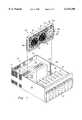
- FIG. 1is a isometric, partially exploded, view of a computer and fan assembly according to an embodiment of the present invention.
- FIG. 2is an isometric view of the fan assembly of FIGS. 1 and 2.
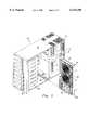
- FIG. 3is view similar to FIG. 1, but depicting a different orientation of the computer and fan assembly of FIG. 1.
- FIG. 1 of the drawingsdepicts a computer 10 according to an embodiment of the present disclosure which, for the purpose of example, is shown in the form of a conventional file server for use in a computer network.
- the server 10includes a chassis 12 formed by a bottom plate 14, a pair of side walls 16 and 18, and a pair of end walls 20 and 22.
- a pair of power supplies 24 and 26are housed within the chassis 12 and are secured in the chassis in any known manner.
- a bank of hard drives shown, in general, by the reference numeral 28,is also secured in the chassis 12 in a spaced relation to the power supplies 24 and 26. Since the power supplies 24 and 26, as well as the bank 28 of hard drives, are conventional, they will not be described in detail. It is understood that additional components, buses, electrical traces, electrical circuits and related devices (not shown) are provided in the chassis 10 but are not shown in the interest of clarity.
- a fan assembly 30is provided and is shown in FIG. 1 in a position spaced above the chassis 12 and oriented for installation in the chassis. In its assembled condition in the chassis 12, the fan assembly 30 is mounted relative to the two side walls 16 and 18 of the chassis in a manner to be described and extends between the hard drive bank 28 and the power supplies 24 and 26.
- the fan assembly 30includes three fans 32, 34, and 36 mounted to a subchassis 38 for drawing air from the portion of the chassis 12 containing the hard drive bank 28 and forcing it to and across the power supplies 24 and 26 for cooling the bank and the power supplies.
- Two finger guards 40 and 42are shown mounted over the inlet ends of the fans 32 and 34, respectively. It is understood that a finger guard identical to the finger guards 40 and 42 is also mounted over the fan 36 but has been omitted from the drawings so that the latter fan can be better described as follows.
- the fan 36includes a propeller blade 36a, a motor (not shown) for driving the blade, and a open-ended housing 36b containing the motor and the blade.
- a flexible tab 37extends from the subchassis 38 and engages the fan housing 36b to secure the housing 36b to the subchassis 38. Since the fan 36 is conventional, and since the other fans 32 and 34 are identical to the fan 36 and are installed in the subchassis 38 in the same manner, they will not be described in detail.
- a pair of mounting flanges 38a and 38bextend from the respective ends of the subchassis 38.
- the flange 38aextends for the length of a side wall of the subchassis 38 and is adapted to extend between a pair of parallel, mounting rails 44a and 44b mounted to the inner surface of the sidewall 16.
- the mounting rails 44a and 44bare spaced apart a distance slightly greater that the width of the flange 38a so as to receive the flange with minimal clearance.
- the flange 38bis mounted on the other sidewall of the chassis 12 and is adapted to extend, with minimal clearance, between a pair of parallel, mounting rails 46a and 46b mounted to the inner surface of the side wall 18.
- the fan assembly 30To insert the fan assembly 30 to the chassis 12, the fan assembly is simply aligned relative to, and lowered towards, the chassis from the position shown in FIG. 1 until the flange 38a extends between the rails 44a and 44b and the flange 38b extends between the rails 46a and 46b. The assembly 30 is then lowered further until it rests on the upper surface of the bottom plate 14. The height of the assembly 30 is such that its upper surface is engaged by the cover, or top plate (not shown), of the chassis 12 when the latter plate is installed over the chassis during final assembly to secure the assembly in the chassis.
- the width of the mounting flange 38b, and the corresponding space between the mounting rails 46a and 46b,are greater than the width of the mounting flange 38a and the space between the mounting rails 44a and 44b. This prevents the flange 38b from being inserted in the space between the rails 44a and 44b, and thus insures that the subchassis 38, and therefore the fans 32, 34 and 36 will be oriented properly relative to the chassis 12.
- the fans 32, 34 and 36are designed to pull air from that portion of the chassis 12 containing the hard drive bank 28 and force the air into that portion of the chassis containing the power supplies 24 and 26. This raises the convective heat transfer coefficient for the surface of the power supplies 24 and 26 and the hard drive bank 28, thereby increasing their convection cooling.
- louversare associated with the outlet end of each of the fans 32, 34 and 36.
- the louvers 50, 52 and 54are mounted to the outlet end of the subchassis 38 and in the path of air flow through the fan 32 with three louvers being referred to by the reference numbers 50, 52 and 54, respectively.
- the louvers 50 and 52are shown slightly spaced from the subchassis 38, and the louver 54 is shown mounted to the subchassis.
- three horizontally extending shafts 50a, 52a, and 54aare disposed along the rear edges of the louvers 50, 52 and 54 and preferably are formed integrally with the louvers.
- three pairs of support brackets 60, 62, and 64are mounted to the subchassis 38, with one bracket of each pair being mounted to the subchassis in a spaced relation to the other bracket of the pair.
- each pair of brackets 60, 62, and 64substantially corresponds to the length of their corresponding shafts 50a, 52a, and 54a, and the respective end portions of the shafts 50a, 52a, and 54a are mounted in the pairs of brackets, 60, 62 and 64, respectively, in a loose fit.
- the shafts 50a, 52a, and 54acan rotate relative to the brackets 60, 62 and 64, respective to cause pivotal movement of the louvers 50, 52, and 54 relative to the subchassis 38 and to the fan 32.
- louvers 50, 52, and 54along with their respective shafts 50a, 52a, and 54a, are symmetrical, thus enabling either end of each shaft to be inserted into either one of the corresponding pairs of support brackets 60, 62, and 64 to facilitate assembly.
- the support brackets 60, 62 and 64are located on the subchassis 38 in a manner so that the shafts 50a, 52a, and 54a, and therefore their respective louvers 50, 52 and 54, extend at an angle to the longitudinal axis of the subchassis 38.
- the louvers 50, 52 and 54will operate when the longitudinal axis of the subchassis 38 extends horizontally as shown in FIGS. 1 and 2, or when it extends vertically as will be described.
- the gravitational forces caused by the weight of the louvers 50, 52 and 54apply a torque, or rotational force, to the shafts 50a, 52a and 54a, respectively, causing the louvers to pivot to a closed position thus blocking the flow of air through the fan 36.
- the resulting air pressure created by the fanis sufficient to force the louvers 50, 52, and 54 to their open position as shown in FIG. 2.
- louvers associated with the fan 36 and all of the louvers associated with each of the fans 32 and 34are identical to the louvers 50, 52 and 54, respectively, are mounted to the subchassis 38 in the same manner as the latter louvers, and function in a manner identical to that of the louvers 50, 52, and 54. Therefore, the remaining louvers associated with the fan 36 and the louvers associated with the fans 32 and 34 will not be described in any further detail.
- FIG. 3is a view similar to that of FIG. 1 but depicts the computer 10, including the fan assembly 30, in a vertical orientation, or "tower" configuration.
- the fan assembly 30is inserted in the chassis 12 by aligning the assembly in a spaced relation to the chassis as shown in FIGS. 1 and 2.
- the assembly 30is then moved towards the chassis 12 until the mounting flange 38a extends between the mounting rails 44a and 44b and the mounting flange 38b extends between the mounting rails 46a and 46b.
- the assembly 30is then moved further into the chassis 12 until the leading surface of the subchassis 38 rests on the corresponding surface of the bottom plate 14.
- the cover, or top plate (not shown), of the chassis 12is then installed over the chassis, and the height of the subchassis 38 is such that the top plate engages the corresponding surface of the subchassis to secure the assembly in the chassis.
- the fans 32, 34 and 36are not operable when the computer 10 is not in use, in which case the louvers 50, 52 and 54 of the fan 36, and the corresponding louvers associated with the fans 32 and 34, pivot to their closed positions in response to the gravitational forces acting on the louvers.
- the fans 32, 34 and 36are activated which draws air from the area in the chassis 12 housing the bank 28 of hard drives (FIGS. 1 and 3) and forces it through the fans 32, 34 and 36 and towards the power supplies 24 and 26.
- This air flow through the fans 32, 34, and 36pivots the louvers 50, 52 and 54 of the fan 36, and the corresponding louvers associated with the fans 34 and 36, to their horizontal, open positions.
- a continuous air flowis achieved which increases the convective cooling of the hard drive bank 28 and the power supplies 24 and 26.
- louvers 50, 52, and 54will pivot to their closed position under the force of gravity which blocks any backflow of air through the fan 36 that may occur if the louvers 50, 52, and 54 were open. This prevention of any backflow of air through the fan 36 eliminates any interference with the normal air flow through the functioning fans 32 and 34. Of course, if the fans 32 and/or 34 should fail, air flow would be prevented by their respective louvers in the same manner.
- the assembly 30is easily removed from the chassis 12 by simple removing the top plate, or cover, of the chassis and sliding the assembly out of the chassis.
- flanges 38a and 38b and the rails 44a, 44b, 46a and 46bcan be employed as long as the function of the latter flanges and rails is achieved.
- the flanges 38a and 38bcan be mounted on the side walls 16 and 18 and the rails 44a, 44b, 46a and 46b can be mounted on the subchassis 38.
- the number of louvers associated with each fan and the number of fans employed in the fan assemblycan be varied within the scope of the disclosure.
- the fan assembly 30can be oriented in the chassis 12 so that it pulls air from the area of the chassis 12 housing the power supplies 24 and 26 towards the area of the chassis housing the hard drive bank 28. Further, only one fan can be employed if it is desired to block air flow through the fan in the above manner under certain conditions.
- the term "computer”is used in its broadest sense and is meant to include all types of computing systems including, but not limited to, laptop computers, central process units, towers, file servers, etc. Further, the present invention is not limited to computers, but is equally applicable to other electronic components that generate heat during use.
Landscapes
- Engineering & Computer Science (AREA)
- General Engineering & Computer Science (AREA)
- Physics & Mathematics (AREA)
- Theoretical Computer Science (AREA)
- Computer Hardware Design (AREA)
- Thermal Sciences (AREA)
- Microelectronics & Electronic Packaging (AREA)
- Human Computer Interaction (AREA)
- General Physics & Mathematics (AREA)
- Cooling Or The Like Of Electrical Apparatus (AREA)
Abstract
Description
Claims (36)
Priority Applications (1)
| Application Number | Priority Date | Filing Date | Title |
|---|---|---|---|
| US09/009,281US6115250A (en) | 1998-01-20 | 1998-01-20 | Computer and an assembly and method for cooling a computer |
Applications Claiming Priority (1)
| Application Number | Priority Date | Filing Date | Title |
|---|---|---|---|
| US09/009,281US6115250A (en) | 1998-01-20 | 1998-01-20 | Computer and an assembly and method for cooling a computer |
Publications (1)
| Publication Number | Publication Date |
|---|---|
| US6115250Atrue US6115250A (en) | 2000-09-05 |
Family
ID=21736699
Family Applications (1)
| Application Number | Title | Priority Date | Filing Date |
|---|---|---|---|
| US09/009,281Expired - LifetimeUS6115250A (en) | 1998-01-20 | 1998-01-20 | Computer and an assembly and method for cooling a computer |
Country Status (1)
| Country | Link |
|---|---|
| US (1) | US6115250A (en) |
Cited By (142)
| Publication number | Priority date | Publication date | Assignee | Title |
|---|---|---|---|---|
| US6269001B1 (en)* | 2000-04-20 | 2001-07-31 | International Business Machines Corporation | System for enhanced cooling and latching of pluggable electronic component |
| US6288897B1 (en)* | 1999-03-18 | 2001-09-11 | Simone Fritschle | Casing with a fan unit and fan unit |
| US6322042B1 (en)* | 2000-07-19 | 2001-11-27 | Lite-On Enclosure Inc. | Extracted and positioning device of a fan |
| US6375440B2 (en)* | 1999-09-30 | 2002-04-23 | Fujitsu Limited | Fan unit, fan assembly, and an apparatus comprising the fan assembly |
| US6388880B1 (en)* | 2000-10-19 | 2002-05-14 | Fijitsu Network Communications, Inc. | Removable fan tray assembly with latching features |
| US6392893B1 (en)* | 2000-11-08 | 2002-05-21 | Sun Microsystems, Inc. | Hot swap fan mounting support bracket |
| US6392872B1 (en)* | 1999-03-15 | 2002-05-21 | Emc Corporation | Computer system |
| US6401475B1 (en) | 2001-04-23 | 2002-06-11 | International Business Machines Corporation | Temperature adjustment module and method using same |
| US6430041B1 (en)* | 1999-10-20 | 2002-08-06 | Micronpc, Llc | Computer cooling system and method |
| US6445581B1 (en)* | 2000-07-12 | 2002-09-03 | Nstor Corporation | Disk drive storage enclosure with isolated cooling path for storage media |
| WO2002089549A1 (en)* | 2001-04-27 | 2002-11-07 | Telefonaktiebolaget Lm Ericsson | Valve |
| US6497398B1 (en)* | 2001-10-10 | 2002-12-24 | Aaeon Technology Inc. | Support using guide slider for interface card |
| US6504717B1 (en)* | 2001-06-15 | 2003-01-07 | Cereva Networks. Inc. | Failure-tolerant high-density card rack cooling system and method |
| US6502628B1 (en)* | 2000-08-16 | 2003-01-07 | Sun Microsystems, Inc. | Method and apparatus for undirectional coolant flow control unit for pressurized cooling systems |
| US6538883B1 (en)* | 2001-09-19 | 2003-03-25 | Turin Networks | Method and apparatus for thermally insulated and earth cooled electronic components within an electronic system |
| US6542362B2 (en)* | 1999-06-28 | 2003-04-01 | Sun Microsystems, Inc. | Computer system housing configuration |
| US6557624B1 (en)* | 2000-08-09 | 2003-05-06 | Liebert Corporation | Configurable system and method for cooling a room |
| US6567271B2 (en)* | 2001-03-05 | 2003-05-20 | Toshiba America Information Systems, Inc. | Circuit board interconnection and fan-mounting assembly for convective cooling |
| US6587340B2 (en)* | 2001-04-10 | 2003-07-01 | Sun Microsystems, Inc. | Maintaining cooling efficiency during air mover failure |
| EP1201930A3 (en)* | 2000-10-24 | 2003-07-09 | Fujitsu Siemens Computers GmbH | Fan unit |
| US6593528B2 (en)* | 1999-11-19 | 2003-07-15 | Alaris Medical Systems, Inc. | Medical device interface system |
| US6646877B2 (en)* | 2000-12-08 | 2003-11-11 | Arthur G. Willers | Cooling system |
| US6650535B1 (en)* | 1999-07-23 | 2003-11-18 | Dell Products L.P. | Fanless power supply |
| US6654252B2 (en)* | 2001-07-18 | 2003-11-25 | Hewlett-Packard Development Company, L.P. | Server system with removable server cartridges |
| US20030224717A1 (en)* | 2002-05-29 | 2003-12-04 | Tsai I-Hsuan | Flow direction control mechanism |
| US6661656B2 (en)* | 2001-09-13 | 2003-12-09 | Sun Microsystems, Inc. | Computer system and enclosure thereof |
| US20030226675A1 (en)* | 2002-06-10 | 2003-12-11 | Osborn Jay Kevin | Electronics assembly |
| US20030227757A1 (en)* | 2002-06-10 | 2003-12-11 | Vincent William Hunt | Electronics assembly |
| US20030227752A1 (en)* | 2002-06-10 | 2003-12-11 | Yair Andrew John | Electronics assembly |
| US20040001320A1 (en)* | 2002-06-28 | 2004-01-01 | Gnp Computers, Inc. | Telecommunication chassis |
| US6714411B2 (en)* | 2001-12-31 | 2004-03-30 | Hewlett-Packard Development Company, L.P. | Computer server hot plug fan tray assembly and method of fan removal |
| US20040130872A1 (en)* | 2003-01-02 | 2004-07-08 | Dell Products L.P. | Removable fan bay |
| US20040184235A1 (en)* | 2003-02-28 | 2004-09-23 | Toyoda Koki Kabushiki Kaisha | Control box |
| USD496939S1 (en) | 2003-05-05 | 2004-10-05 | Motorola, Inc. | Sealed central processing unit cooling apparatus |
| US20040201962A1 (en)* | 2003-04-11 | 2004-10-14 | Patrick Lao | Computer component mounting system |
| US20040218360A1 (en)* | 2003-05-02 | 2004-11-04 | Delta Electronics, Inc. | Heat-dispersing fan module of electronic apparatus |
| US20040252453A1 (en)* | 2003-06-11 | 2004-12-16 | Hewlett-Packard Development Company, L.P. | Computer cooling system and method |
| US20040252456A1 (en)* | 2003-06-11 | 2004-12-16 | Hewlett-Packard Development Company, L.P. | Computer cooling system and method |
| US20050041391A1 (en)* | 2003-08-19 | 2005-02-24 | Sun Microsystems, Inc. | Electronics assembly with arrangement for air cooling |
| US20050088818A1 (en)* | 2003-10-23 | 2005-04-28 | Tatung Co., Ltd. | Backflow-preventive fan module |
| US20050135058A1 (en)* | 2003-12-23 | 2005-06-23 | Etienne Merlet | Ventilation system for electrical of electronic equipment |
| US20050145375A1 (en)* | 2004-01-07 | 2005-07-07 | Shu-Ju Lin | Radiator |
| US20050162831A1 (en)* | 2004-01-28 | 2005-07-28 | Shum Kent N. | Modular electronic enclosure with cooling design |
| US20050254210A1 (en)* | 2004-05-14 | 2005-11-17 | Grady John R | Fan tray for electronics enclosure |
| US20050259397A1 (en)* | 2004-05-21 | 2005-11-24 | Bash Cullen E | Small form factor liquid loop cooling system |
| US20060120041A1 (en)* | 2004-12-06 | 2006-06-08 | Chenbro Micom Co., Ltd | [cooler] |
| US20060148399A1 (en)* | 2004-12-22 | 2006-07-06 | Chi-Min Su | Louver heat vent for chassis of computer |
| US20070008699A1 (en)* | 2005-07-11 | 2007-01-11 | Dell Products L.P. | Method and apparatus for regulating airflow in a chassis |
| US20070035925A1 (en)* | 2005-08-09 | 2007-02-15 | Norio Kobayashi | Information-processing apparatus and cooling system used therein |
| US20070064386A1 (en)* | 2005-09-21 | 2007-03-22 | Hon Hai Precision Industry Co., Ltd. | Cooling apparatus for computer system |
| US20070109741A1 (en)* | 2005-11-17 | 2007-05-17 | Rackable Systems, Inc. | Power supply cooling system |
| US20070109744A1 (en)* | 2005-11-11 | 2007-05-17 | Hitoshi Matsushima | Disk array apparatus |
| US20070133167A1 (en)* | 2005-12-09 | 2007-06-14 | Wagner Barry A | Computer chassis for improved airflow and heat transfer from computer system components |
| US20070230112A1 (en)* | 2006-04-03 | 2007-10-04 | Accton Technology Corporation | Network apparatus |
| US20070227710A1 (en)* | 2006-04-03 | 2007-10-04 | Belady Christian L | Cooling system for electrical devices |
| US20080002357A1 (en)* | 2006-06-30 | 2008-01-03 | Lenovo (Singapore) Pte. Ltd. | Thermal docking fansink |
| US20080055868A1 (en)* | 2006-08-29 | 2008-03-06 | Peterson Eric C | Cabled module, multi-processor system architecture |
| US20080056900A1 (en)* | 2006-09-05 | 2008-03-06 | Siegfried Seidler | Fan with integrated nonreturn flaps |
| US20080117591A1 (en)* | 2006-11-16 | 2008-05-22 | Autonetworks Technologies, Ltd. | Electric connection box |
| US20080117589A1 (en)* | 2006-11-22 | 2008-05-22 | Dell Products L.P. | Self Adjusting Air Directing Baffle |
| US20080130227A1 (en)* | 2006-11-30 | 2008-06-05 | Kabushiki Kaisha Toshiba | Electronic apparatus |
| US20080138194A1 (en)* | 2006-12-11 | 2008-06-12 | Delta Electronics, Inc. | Frame Structure Of A Cooling Fan, The Cooling Fan And Heat Generating Device Having The Fan |
| US20080151490A1 (en)* | 2006-12-22 | 2008-06-26 | Hon Hai Precision Industry Co., Ltd. | Airflow-guiding device |
| US20080212273A1 (en)* | 2006-01-13 | 2008-09-04 | Sun Microsystems, Inc. | Compact rackmount storage server |
| US20080253084A1 (en)* | 2007-04-13 | 2008-10-16 | Wen-Bin Chen | Computer casing with a backside cooling cpu heat dissipating function |
| US20080273305A1 (en)* | 2007-05-01 | 2008-11-06 | Jia-Shiung Lee | Fan airflow-guiding device |
| US20080310103A1 (en)* | 2007-06-04 | 2008-12-18 | Della Fiora Troy A | Air backflow prevention in an enclosure |
| US20090021912A1 (en)* | 2007-07-20 | 2009-01-22 | Hong Fu Jin Precision Industry (Shenzhen) Co., Ltd. | Fan holder for receiving multiple fans |
| US20090034190A1 (en)* | 2007-08-03 | 2009-02-05 | Hon Hai Precision Industry Co., Ltd. | Airflow-guiding device and computer having same |
| US20090257187A1 (en)* | 2008-04-11 | 2009-10-15 | Dell Products L.P. | Information Handling System with Chassis Design for Storage Device Access |
| US20100027213A1 (en)* | 2008-07-31 | 2010-02-04 | Inventec Corporation | Server |
| US20100048120A1 (en)* | 2008-08-25 | 2010-02-25 | Wistron Corporation | Adjustable air vent device for a computer housing, and assembly of a computer housing and the adjustable air vent device |
| US20100087956A1 (en)* | 2008-10-03 | 2010-04-08 | Dell Products L.P. | Spring-loaded doors to prevent air recirculation without need for additional space |
| US7778031B1 (en) | 2009-07-15 | 2010-08-17 | Teradyne, Inc. | Test slot cooling system for a storage device testing system |
| US20100246114A1 (en)* | 2009-03-27 | 2010-09-30 | Lenovo (Singapore) Pte. Ltd. | Tool-less retention system for an electronic device |
| US20100270897A1 (en)* | 2009-04-23 | 2010-10-28 | Lin Te-Chang | Industrial computer chassis structure with power source disposed centrally |
| US7848106B2 (en) | 2008-04-17 | 2010-12-07 | Teradyne, Inc. | Temperature control within disk drive testing systems |
| US20110028081A1 (en)* | 2009-07-29 | 2011-02-03 | Huntair, Inc. | Back draft damper |
| US7890207B2 (en) | 2008-04-17 | 2011-02-15 | Teradyne, Inc. | Transferring storage devices within storage device testing systems |
| US7904211B2 (en) | 2008-04-17 | 2011-03-08 | Teradyne, Inc. | Dependent temperature control within disk drive testing systems |
| US7908029B2 (en) | 2008-06-03 | 2011-03-15 | Teradyne, Inc. | Processing storage devices |
| US7911778B2 (en) | 2008-04-17 | 2011-03-22 | Teradyne, Inc. | Vibration isolation within disk drive testing systems |
| US7929303B1 (en) | 2010-02-02 | 2011-04-19 | Teradyne, Inc. | Storage device testing system cooling |
| US7932734B2 (en) | 2009-07-15 | 2011-04-26 | Teradyne, Inc. | Individually heating storage devices in a testing system |
| US7940529B2 (en) | 2009-07-15 | 2011-05-10 | Teradyne, Inc. | Storage device temperature sensing |
| US7945424B2 (en) | 2008-04-17 | 2011-05-17 | Teradyne, Inc. | Disk drive emulator and method of use thereof |
| US20110116909A1 (en)* | 2008-12-08 | 2011-05-19 | Norbert Weisser | Ventilator |
| US20110141688A1 (en)* | 2009-12-15 | 2011-06-16 | Hong Fu Jin Precision Industry (Shenzhen) Co., Ltd. | Computer system with airflow blocking plate |
| US7987018B2 (en) | 2008-04-17 | 2011-07-26 | Teradyne, Inc. | Transferring disk drives within disk drive testing systems |
| US7996174B2 (en) | 2007-12-18 | 2011-08-09 | Teradyne, Inc. | Disk drive testing |
| US20110222227A1 (en)* | 2010-03-15 | 2011-09-15 | Inventec Corporation | Server auxiliary operating system |
| US8041449B2 (en) | 2008-04-17 | 2011-10-18 | Teradyne, Inc. | Bulk feeding disk drives to disk drive testing systems |
| US8045328B1 (en)* | 2010-05-04 | 2011-10-25 | Chenbro Micom Co., Ltd. | Server and cooler moduel arrangement |
| US8102173B2 (en) | 2008-04-17 | 2012-01-24 | Teradyne, Inc. | Thermal control system for test slot of test rack for disk drive testing system with thermoelectric device and a cooling conduit |
| US8116079B2 (en) | 2009-07-15 | 2012-02-14 | Teradyne, Inc. | Storage device testing system cooling |
| EP2106206A3 (en)* | 2008-03-28 | 2012-02-22 | Fujitsu Limited | Cooling device for accomodated printed circuit board in a chassis |
| US20120147549A1 (en)* | 2010-12-08 | 2012-06-14 | Hon Hai Precision Industry Co., Ltd. | Rack server |
| CN102052330B (en)* | 2009-10-27 | 2012-07-04 | 英业达股份有限公司 | Fan module |
| US8238099B2 (en) | 2008-04-17 | 2012-08-07 | Teradyne, Inc. | Enclosed operating area for disk drive testing systems |
| CN101761498B (en)* | 2010-01-14 | 2012-11-28 | 杭州六易科技有限公司 | Fan with freely distributed air quantity |
| US8405971B2 (en) | 2007-12-18 | 2013-03-26 | Teradyne, Inc. | Disk drive transport, clamping and testing |
| US8482915B2 (en) | 2008-04-17 | 2013-07-09 | Teradyne, Inc. | Temperature control within disk drive testing systems |
| US8547123B2 (en) | 2009-07-15 | 2013-10-01 | Teradyne, Inc. | Storage device testing system with a conductive heating assembly |
| US8570743B2 (en)* | 2012-03-08 | 2013-10-29 | Hong Fu Jin Precision Industry (Shenzhen) Co., Ltd. | Mounting apparatus for fans |
| US8628239B2 (en) | 2009-07-15 | 2014-01-14 | Teradyne, Inc. | Storage device temperature sensing |
| US8687349B2 (en) | 2010-07-21 | 2014-04-01 | Teradyne, Inc. | Bulk transfer of storage devices using manual loading |
| US9001456B2 (en) | 2010-08-31 | 2015-04-07 | Teradyne, Inc. | Engaging test slots |
| US9091455B1 (en)* | 2011-10-12 | 2015-07-28 | Jan B. Coster | Swamp cooler blower fan hole cover |
| US20160095258A1 (en)* | 2014-09-29 | 2016-03-31 | International Business Machines Corporation | Protective louver assembly for air-moving assembly |
| US9426932B2 (en) | 2013-03-13 | 2016-08-23 | Silicon Graphics International Corp. | Server with heat pipe cooling |
| US9459312B2 (en) | 2013-04-10 | 2016-10-04 | Teradyne, Inc. | Electronic assembly test system |
| US9605868B2 (en) | 2013-03-14 | 2017-03-28 | Mitek Holdings, Inc. | Fan array backflow preventer |
| US9612920B2 (en) | 2013-03-15 | 2017-04-04 | Silicon Graphics International Corp. | Hierarchical system manager rollback |
| US9629284B2 (en) | 2014-09-29 | 2017-04-18 | International Business Machines Corporation | Interlock assembly for air-moving assembly |
| US9661787B2 (en)* | 2015-06-29 | 2017-05-23 | Telefonaktiebolaget Lm Ericsson (Publ) | Facilitating front access to rear-mounted assembly in equipment chassis |
| US9717169B2 (en)* | 2015-09-28 | 2017-07-25 | Lenovo Enterprise Solutions (Singapore) Pte. Ltd. | Mitigating electromagnetic interference in a computing device |
| US9779780B2 (en) | 2010-06-17 | 2017-10-03 | Teradyne, Inc. | Damping vibrations within storage device testing systems |
| US9907211B2 (en) | 2014-09-29 | 2018-02-27 | International Business Machines Corporation | Locking louver assembly for air-moving assembly |
| US9941041B2 (en) | 2015-04-08 | 2018-04-10 | International Business Machines Corporation | Electromechanical assembly controlled by sensed voltage |
| US10271459B2 (en) | 2014-12-10 | 2019-04-23 | International Business Machines Corporation | Protective cover assembly for air-moving assembly |
| US20190146562A1 (en)* | 2017-11-15 | 2019-05-16 | Fujitsu Client Computing Limited | Computer arrangement with air-conducting element, and air-conducting element |
| US20190234647A1 (en)* | 2018-01-30 | 2019-08-01 | Quanta Computer Inc. | Louver integrated design for fan module |
| US10595437B2 (en)* | 2018-07-27 | 2020-03-17 | Dell Products, L.P. | Information handling system with modular fan gantry having different mounting variations |
| US10643923B2 (en)* | 2016-09-30 | 2020-05-05 | Sungrow Power Supply Co., Ltd. | Case and electronic device having the same |
| US10725091B2 (en) | 2017-08-28 | 2020-07-28 | Teradyne, Inc. | Automated test system having multiple stages |
| US10775408B2 (en) | 2018-08-20 | 2020-09-15 | Teradyne, Inc. | System for testing devices inside of carriers |
| US10845410B2 (en) | 2017-08-28 | 2020-11-24 | Teradyne, Inc. | Automated test system having orthogonal robots |
| US10917993B1 (en)* | 2019-11-18 | 2021-02-09 | Inventec (Pudong) Technology Corporation | Fan gantry |
| US10948534B2 (en) | 2017-08-28 | 2021-03-16 | Teradyne, Inc. | Automated test system employing robotics |
| US10983145B2 (en) | 2018-04-24 | 2021-04-20 | Teradyne, Inc. | System for testing devices inside of carriers |
| US11039548B1 (en)* | 2020-03-27 | 2021-06-15 | Dell Products L.P. | Flexible air baffle supporting different configurations with optimized air flow |
| US11226390B2 (en) | 2017-08-28 | 2022-01-18 | Teradyne, Inc. | Calibration process for an automated test system |
| US11369118B2 (en) | 2017-04-07 | 2022-06-28 | The Middleby Corporation | Conveyor oven heat delivery system |
| US11371103B2 (en)* | 2020-10-02 | 2022-06-28 | Alternative Sustainability IP LLC | Energy recapturing apparatus |
| US11369117B2 (en)* | 2018-12-20 | 2022-06-28 | The Middleby Corporation | Conveyor oven air system |
| US20220210944A1 (en)* | 2020-12-24 | 2022-06-30 | Dell Products, Lp | Information handling system with a tandem fan package |
| US11754596B2 (en) | 2020-10-22 | 2023-09-12 | Teradyne, Inc. | Test site configuration in an automated test system |
| US11754622B2 (en) | 2020-10-22 | 2023-09-12 | Teradyne, Inc. | Thermal control system for an automated test system |
| US11867749B2 (en) | 2020-10-22 | 2024-01-09 | Teradyne, Inc. | Vision system for an automated test system |
| US11899042B2 (en) | 2020-10-22 | 2024-02-13 | Teradyne, Inc. | Automated test system |
| US11953519B2 (en) | 2020-10-22 | 2024-04-09 | Teradyne, Inc. | Modular automated test system |
| US12007411B2 (en) | 2021-06-22 | 2024-06-11 | Teradyne, Inc. | Test socket having an automated lid |
Citations (7)
| Publication number | Priority date | Publication date | Assignee | Title |
|---|---|---|---|---|
| US4931904A (en)* | 1989-05-30 | 1990-06-05 | Motorola, Inc. | Localized circuit card cooling device |
| US5208730A (en)* | 1991-06-27 | 1993-05-04 | Compaq Computer Corporation | Computer cooling fan vibration isolation apparatus |
| US5617572A (en)* | 1995-01-31 | 1997-04-01 | Dell Usa, L.P. | System for reducing power consumption in computers |
| US5625227A (en)* | 1995-01-18 | 1997-04-29 | Dell Usa, L.P. | Circuit board-mounted IC package cooling apparatus |
| US5713790A (en)* | 1996-09-03 | 1998-02-03 | Inventec Corporation | Embedded heat dissipating device mounting structure |
| US5793610A (en)* | 1996-01-25 | 1998-08-11 | Dell Usa, L.P. | Multi-position air regulation device |
| US5793608A (en)* | 1996-06-11 | 1998-08-11 | Sun Microsystems, Inc. | Cooling system for enclosed electronic components |
- 1998
- 1998-01-20USUS09/009,281patent/US6115250A/ennot_activeExpired - Lifetime
Patent Citations (7)
| Publication number | Priority date | Publication date | Assignee | Title |
|---|---|---|---|---|
| US4931904A (en)* | 1989-05-30 | 1990-06-05 | Motorola, Inc. | Localized circuit card cooling device |
| US5208730A (en)* | 1991-06-27 | 1993-05-04 | Compaq Computer Corporation | Computer cooling fan vibration isolation apparatus |
| US5625227A (en)* | 1995-01-18 | 1997-04-29 | Dell Usa, L.P. | Circuit board-mounted IC package cooling apparatus |
| US5617572A (en)* | 1995-01-31 | 1997-04-01 | Dell Usa, L.P. | System for reducing power consumption in computers |
| US5793610A (en)* | 1996-01-25 | 1998-08-11 | Dell Usa, L.P. | Multi-position air regulation device |
| US5793608A (en)* | 1996-06-11 | 1998-08-11 | Sun Microsystems, Inc. | Cooling system for enclosed electronic components |
| US5713790A (en)* | 1996-09-03 | 1998-02-03 | Inventec Corporation | Embedded heat dissipating device mounting structure |
Non-Patent Citations (5)
| Title |
|---|
| U.S. Patent application No. 08/374,266, filed on Jan. 18, 1995, Mills, Plenum Bypass Serial Fan Cooling Substystem For Computer Systems, Abstract, 2 sheet of drawings, and filing receipt.* |
| U.S. Patent application No. 08/644,582, filed on May 10, 1996, Jeffries et al., Heat Dissipator With Multiple Thermal Cooling Paths, Abstract, 2 sheets of drawings, and filing receipt.* |
| U.S. Patent application No. 08/754,965, filed Nov. 22, 1996, Estes et al., Circuit Board Mounted IC Package Cooling Apparatus and Methods, Abstract, 1 sheet of drawings, and filing receipt.* |
| U.S. Patent application No. 08/754,965, filed Nov. 22, 1996, Estes et al., Circuit Board-Mounted IC Package Cooling Apparatus and Methods, Abstract, 1 sheet of drawings, and filing receipt. |
| U.S. Patent application No. 08/889,287, filed Jul. 8, 1997, Moss et al., Computer With Docking Station for Docking and Cooling the Computer, Abstract, 4 sheets of drawings, and filing receipt.* |
Cited By (217)
| Publication number | Priority date | Publication date | Assignee | Title |
|---|---|---|---|---|
| US6392872B1 (en)* | 1999-03-15 | 2002-05-21 | Emc Corporation | Computer system |
| US6288897B1 (en)* | 1999-03-18 | 2001-09-11 | Simone Fritschle | Casing with a fan unit and fan unit |
| US6542362B2 (en)* | 1999-06-28 | 2003-04-01 | Sun Microsystems, Inc. | Computer system housing configuration |
| US6650535B1 (en)* | 1999-07-23 | 2003-11-18 | Dell Products L.P. | Fanless power supply |
| US6375440B2 (en)* | 1999-09-30 | 2002-04-23 | Fujitsu Limited | Fan unit, fan assembly, and an apparatus comprising the fan assembly |
| US6430041B1 (en)* | 1999-10-20 | 2002-08-06 | Micronpc, Llc | Computer cooling system and method |
| US6593528B2 (en)* | 1999-11-19 | 2003-07-15 | Alaris Medical Systems, Inc. | Medical device interface system |
| US6269001B1 (en)* | 2000-04-20 | 2001-07-31 | International Business Machines Corporation | System for enhanced cooling and latching of pluggable electronic component |
| US6445581B1 (en)* | 2000-07-12 | 2002-09-03 | Nstor Corporation | Disk drive storage enclosure with isolated cooling path for storage media |
| US6322042B1 (en)* | 2000-07-19 | 2001-11-27 | Lite-On Enclosure Inc. | Extracted and positioning device of a fan |
| US6557624B1 (en)* | 2000-08-09 | 2003-05-06 | Liebert Corporation | Configurable system and method for cooling a room |
| US6502628B1 (en)* | 2000-08-16 | 2003-01-07 | Sun Microsystems, Inc. | Method and apparatus for undirectional coolant flow control unit for pressurized cooling systems |
| US6388880B1 (en)* | 2000-10-19 | 2002-05-14 | Fijitsu Network Communications, Inc. | Removable fan tray assembly with latching features |
| EP1201930A3 (en)* | 2000-10-24 | 2003-07-09 | Fujitsu Siemens Computers GmbH | Fan unit |
| US6392893B1 (en)* | 2000-11-08 | 2002-05-21 | Sun Microsystems, Inc. | Hot swap fan mounting support bracket |
| US6646877B2 (en)* | 2000-12-08 | 2003-11-11 | Arthur G. Willers | Cooling system |
| US6567271B2 (en)* | 2001-03-05 | 2003-05-20 | Toshiba America Information Systems, Inc. | Circuit board interconnection and fan-mounting assembly for convective cooling |
| US6587340B2 (en)* | 2001-04-10 | 2003-07-01 | Sun Microsystems, Inc. | Maintaining cooling efficiency during air mover failure |
| US6401475B1 (en) | 2001-04-23 | 2002-06-11 | International Business Machines Corporation | Temperature adjustment module and method using same |
| WO2002089549A1 (en)* | 2001-04-27 | 2002-11-07 | Telefonaktiebolaget Lm Ericsson | Valve |
| US6837785B2 (en)* | 2001-04-27 | 2005-01-04 | Telefonaktiebolaget Lm Ericsson (Publ) | Check valve, fan unit, and forced air cooling system |
| US20040129410A1 (en)* | 2001-04-27 | 2004-07-08 | Per Thomas Soderlund | Valve |
| US6504717B1 (en)* | 2001-06-15 | 2003-01-07 | Cereva Networks. Inc. | Failure-tolerant high-density card rack cooling system and method |
| US6654252B2 (en)* | 2001-07-18 | 2003-11-25 | Hewlett-Packard Development Company, L.P. | Server system with removable server cartridges |
| US6661656B2 (en)* | 2001-09-13 | 2003-12-09 | Sun Microsystems, Inc. | Computer system and enclosure thereof |
| US6804114B1 (en) | 2001-09-19 | 2004-10-12 | Turin Networks | Method and apparatus for thermally insulated and earth cooled electronic components within an electronic system |
| US6538883B1 (en)* | 2001-09-19 | 2003-03-25 | Turin Networks | Method and apparatus for thermally insulated and earth cooled electronic components within an electronic system |
| US6497398B1 (en)* | 2001-10-10 | 2002-12-24 | Aaeon Technology Inc. | Support using guide slider for interface card |
| US20040075983A1 (en)* | 2001-12-31 | 2004-04-22 | Thompson Daniel T. | Computer server hot plug fan tray assembly and method of fan removal |
| US6985358B2 (en) | 2001-12-31 | 2006-01-10 | Hewlett-Packard Development Company, L.P. | Computer chassis with fan tray assembly |
| US6714411B2 (en)* | 2001-12-31 | 2004-03-30 | Hewlett-Packard Development Company, L.P. | Computer server hot plug fan tray assembly and method of fan removal |
| US20030224717A1 (en)* | 2002-05-29 | 2003-12-04 | Tsai I-Hsuan | Flow direction control mechanism |
| US6991533B2 (en)* | 2002-05-29 | 2006-01-31 | Delta Electronics, Inc. | Flow direction control mechanism |
| US20060073783A1 (en)* | 2002-05-29 | 2006-04-06 | Tsai I-Hsuan | Flow direction control mechanism |
| US20030227752A1 (en)* | 2002-06-10 | 2003-12-11 | Yair Andrew John | Electronics assembly |
| US20030226675A1 (en)* | 2002-06-10 | 2003-12-11 | Osborn Jay Kevin | Electronics assembly |
| US20030227757A1 (en)* | 2002-06-10 | 2003-12-11 | Vincent William Hunt | Electronics assembly |
| US6961248B2 (en) | 2002-06-10 | 2005-11-01 | Sun Microsystems, Inc. | Electronics assembly |
| US6878874B2 (en)* | 2002-06-10 | 2005-04-12 | Sun Microsystems, Inc. | Electronics assembly |
| US6833994B2 (en) | 2002-06-10 | 2004-12-21 | Sun Microsystems, Inc. | Electronics assembly |
| US6853551B2 (en)* | 2002-06-28 | 2005-02-08 | Gnp Computers, Inc. | Telecommunication chassis |
| US20040001320A1 (en)* | 2002-06-28 | 2004-01-01 | Gnp Computers, Inc. | Telecommunication chassis |
| US6839233B2 (en)* | 2003-01-02 | 2005-01-04 | Dell Products L.P. | Removable fan bay |
| US20040130872A1 (en)* | 2003-01-02 | 2004-07-08 | Dell Products L.P. | Removable fan bay |
| US20040184235A1 (en)* | 2003-02-28 | 2004-09-23 | Toyoda Koki Kabushiki Kaisha | Control box |
| US7082030B2 (en)* | 2003-02-28 | 2006-07-25 | Toyoda Koki Kabushiki Kaisha | Control box |
| US20040201962A1 (en)* | 2003-04-11 | 2004-10-14 | Patrick Lao | Computer component mounting system |
| US7002796B2 (en)* | 2003-04-11 | 2006-02-21 | Hon Hai Precision Ind. Co., Ltd. | Computer component mounting system |
| US20040218360A1 (en)* | 2003-05-02 | 2004-11-04 | Delta Electronics, Inc. | Heat-dispersing fan module of electronic apparatus |
| US6995979B2 (en)* | 2003-05-02 | 2006-02-07 | Delta Electronics, Inc. | Heat-dissipating fan module of electronic apparatus |
| USD496939S1 (en) | 2003-05-05 | 2004-10-05 | Motorola, Inc. | Sealed central processing unit cooling apparatus |
| US20040252456A1 (en)* | 2003-06-11 | 2004-12-16 | Hewlett-Packard Development Company, L.P. | Computer cooling system and method |
| US7075788B2 (en) | 2003-06-11 | 2006-07-11 | Hewlett-Packard Development Company, L.P. | Computer cooling system and method |
| US7079387B2 (en)* | 2003-06-11 | 2006-07-18 | Hewlett-Packard Development Company, L.P. | Computer cooling system and method |
| US20040252453A1 (en)* | 2003-06-11 | 2004-12-16 | Hewlett-Packard Development Company, L.P. | Computer cooling system and method |
| US20050041391A1 (en)* | 2003-08-19 | 2005-02-24 | Sun Microsystems, Inc. | Electronics assembly with arrangement for air cooling |
| US7027299B2 (en) | 2003-08-19 | 2006-04-11 | Sun Microsystems, Inc. | Electronics assembly with arrangement for air cooling |
| US20050088818A1 (en)* | 2003-10-23 | 2005-04-28 | Tatung Co., Ltd. | Backflow-preventive fan module |
| US7209350B2 (en)* | 2003-12-23 | 2007-04-24 | Sagem Sa | Ventilation system for electrical of electronic equipment |
| US20050135058A1 (en)* | 2003-12-23 | 2005-06-23 | Etienne Merlet | Ventilation system for electrical of electronic equipment |
| US6938683B2 (en)* | 2004-01-07 | 2005-09-06 | Inventec Corporation | Radiator |
| US20050145375A1 (en)* | 2004-01-07 | 2005-07-07 | Shu-Ju Lin | Radiator |
| US20050162831A1 (en)* | 2004-01-28 | 2005-07-28 | Shum Kent N. | Modular electronic enclosure with cooling design |
| US6980435B2 (en)* | 2004-01-28 | 2005-12-27 | Hewlett-Packard Development Company, L.P. | Modular electronic enclosure with cooling design |
| US7408772B2 (en)* | 2004-05-14 | 2008-08-05 | Hewlett-Packard Development Company, L.P. | Fan tray electronics enclosure |
| US20050254210A1 (en)* | 2004-05-14 | 2005-11-17 | Grady John R | Fan tray for electronics enclosure |
| US7203063B2 (en)* | 2004-05-21 | 2007-04-10 | Hewlett-Packard Development Company, L.P. | Small form factor liquid loop cooling system |
| US20050259397A1 (en)* | 2004-05-21 | 2005-11-24 | Bash Cullen E | Small form factor liquid loop cooling system |
| US20060120041A1 (en)* | 2004-12-06 | 2006-06-08 | Chenbro Micom Co., Ltd | [cooler] |
| US7312989B2 (en)* | 2004-12-06 | 2007-12-25 | Chenbro Micom Co., Ltd. | Cooler |
| US7201651B2 (en)* | 2004-12-22 | 2007-04-10 | Chi-Min Su | Louver heat vent for chassis of computer |
| US20060148399A1 (en)* | 2004-12-22 | 2006-07-06 | Chi-Min Su | Louver heat vent for chassis of computer |
| US20070008699A1 (en)* | 2005-07-11 | 2007-01-11 | Dell Products L.P. | Method and apparatus for regulating airflow in a chassis |
| US7397660B2 (en)* | 2005-07-11 | 2008-07-08 | Dell Products L.P. | Method and apparatus for regulating airflow in a chassis |
| US7593223B2 (en)* | 2005-08-09 | 2009-09-22 | Sony Corporation | Information-processing apparatus and cooling system used therein |
| US20070035925A1 (en)* | 2005-08-09 | 2007-02-15 | Norio Kobayashi | Information-processing apparatus and cooling system used therein |
| US7304843B2 (en)* | 2005-09-21 | 2007-12-04 | Hong Fu Jin Precision Industry (Shenzhen) Co., Ltd. | Cooling apparatus for computer system |
| US20070064386A1 (en)* | 2005-09-21 | 2007-03-22 | Hon Hai Precision Industry Co., Ltd. | Cooling apparatus for computer system |
| US7369406B2 (en)* | 2005-11-11 | 2008-05-06 | Hitachi, Ltd. | Disk array apparatus |
| US20070109744A1 (en)* | 2005-11-11 | 2007-05-17 | Hitoshi Matsushima | Disk array apparatus |
| US7535707B2 (en)* | 2005-11-17 | 2009-05-19 | Rackable Systems, Inc. | Power supply cooling system |
| US20070109741A1 (en)* | 2005-11-17 | 2007-05-17 | Rackable Systems, Inc. | Power supply cooling system |
| US20070133167A1 (en)* | 2005-12-09 | 2007-06-14 | Wagner Barry A | Computer chassis for improved airflow and heat transfer from computer system components |
| US7885062B2 (en)* | 2005-12-09 | 2011-02-08 | Nvidia Corporation | Computer chassis with partitions for improved airflow |
| US7791894B2 (en)* | 2006-01-13 | 2010-09-07 | Oracle America, Inc. | Compact rackmount storage server |
| US20080212273A1 (en)* | 2006-01-13 | 2008-09-04 | Sun Microsystems, Inc. | Compact rackmount storage server |
| US20070227710A1 (en)* | 2006-04-03 | 2007-10-04 | Belady Christian L | Cooling system for electrical devices |
| US20070230112A1 (en)* | 2006-04-03 | 2007-10-04 | Accton Technology Corporation | Network apparatus |
| US20080002357A1 (en)* | 2006-06-30 | 2008-01-03 | Lenovo (Singapore) Pte. Ltd. | Thermal docking fansink |
| US7529085B2 (en)* | 2006-06-30 | 2009-05-05 | Lenovo (Singapore) Pte. Ltd. | Thermal docking fansink |
| US20080055868A1 (en)* | 2006-08-29 | 2008-03-06 | Peterson Eric C | Cabled module, multi-processor system architecture |
| US8057161B2 (en)* | 2006-09-05 | 2011-11-15 | Ebm-Papst St. Georgen Gmbh & Co. Kg | Fan with integrated nonreturn flaps |
| US20080056900A1 (en)* | 2006-09-05 | 2008-03-06 | Siegfried Seidler | Fan with integrated nonreturn flaps |
| US8654528B2 (en)* | 2006-11-16 | 2014-02-18 | Autonetworks Technologies, Ltd. | Electric connection box |
| US20080117591A1 (en)* | 2006-11-16 | 2008-05-22 | Autonetworks Technologies, Ltd. | Electric connection box |
| US20080117589A1 (en)* | 2006-11-22 | 2008-05-22 | Dell Products L.P. | Self Adjusting Air Directing Baffle |
| US20080130227A1 (en)* | 2006-11-30 | 2008-06-05 | Kabushiki Kaisha Toshiba | Electronic apparatus |
| US20080138194A1 (en)* | 2006-12-11 | 2008-06-12 | Delta Electronics, Inc. | Frame Structure Of A Cooling Fan, The Cooling Fan And Heat Generating Device Having The Fan |
| US7535709B2 (en)* | 2006-12-22 | 2009-05-19 | Hong Fu Jin Precision Industry (Shenzhen) Co., Ltd. | Airflow-guiding device |
| US20080151490A1 (en)* | 2006-12-22 | 2008-06-26 | Hon Hai Precision Industry Co., Ltd. | Airflow-guiding device |
| US20080253084A1 (en)* | 2007-04-13 | 2008-10-16 | Wen-Bin Chen | Computer casing with a backside cooling cpu heat dissipating function |
| US7583498B2 (en)* | 2007-04-13 | 2009-09-01 | Solleron Corporation | Computer casing with a backside cooling CPU heat dissipating function |
| US20080273305A1 (en)* | 2007-05-01 | 2008-11-06 | Jia-Shiung Lee | Fan airflow-guiding device |
| US20080310103A1 (en)* | 2007-06-04 | 2008-12-18 | Della Fiora Troy A | Air backflow prevention in an enclosure |
| US7800902B2 (en)* | 2007-06-04 | 2010-09-21 | Hewlett-Packard Development Company, L.P. | Air backflow prevention in an enclosure |
| US20090021912A1 (en)* | 2007-07-20 | 2009-01-22 | Hong Fu Jin Precision Industry (Shenzhen) Co., Ltd. | Fan holder for receiving multiple fans |
| US7511955B2 (en)* | 2007-07-20 | 2009-03-31 | Hong Fu Jin Precision Industry (Shenzhen) Co., Ltd. | Fan holder for receiving multiple fans |
| US20090034190A1 (en)* | 2007-08-03 | 2009-02-05 | Hon Hai Precision Industry Co., Ltd. | Airflow-guiding device and computer having same |
| US7542289B2 (en)* | 2007-08-03 | 2009-06-02 | Hon Hai Precision Industry Co., Ltd. | Airflow-guiding device and computer having same |
| US8549912B2 (en) | 2007-12-18 | 2013-10-08 | Teradyne, Inc. | Disk drive transport, clamping and testing |
| US8467180B2 (en) | 2007-12-18 | 2013-06-18 | Teradyne, Inc. | Disk drive transport, clamping and testing |
| US8405971B2 (en) | 2007-12-18 | 2013-03-26 | Teradyne, Inc. | Disk drive transport, clamping and testing |
| US7996174B2 (en) | 2007-12-18 | 2011-08-09 | Teradyne, Inc. | Disk drive testing |
| EP2106206A3 (en)* | 2008-03-28 | 2012-02-22 | Fujitsu Limited | Cooling device for accomodated printed circuit board in a chassis |
| US20090257187A1 (en)* | 2008-04-11 | 2009-10-15 | Dell Products L.P. | Information Handling System with Chassis Design for Storage Device Access |
| US8655482B2 (en) | 2008-04-17 | 2014-02-18 | Teradyne, Inc. | Enclosed operating area for storage device testing systems |
| US7848106B2 (en) | 2008-04-17 | 2010-12-07 | Teradyne, Inc. | Temperature control within disk drive testing systems |
| US7890207B2 (en) | 2008-04-17 | 2011-02-15 | Teradyne, Inc. | Transferring storage devices within storage device testing systems |
| US7904211B2 (en) | 2008-04-17 | 2011-03-08 | Teradyne, Inc. | Dependent temperature control within disk drive testing systems |
| US8140182B2 (en) | 2008-04-17 | 2012-03-20 | Teradyne, Inc. | Bulk feeding disk drives to disk drive testing systems |
| US7911778B2 (en) | 2008-04-17 | 2011-03-22 | Teradyne, Inc. | Vibration isolation within disk drive testing systems |
| US8117480B2 (en) | 2008-04-17 | 2012-02-14 | Teradyne, Inc. | Dependent temperature control within disk drive testing systems |
| US8712580B2 (en) | 2008-04-17 | 2014-04-29 | Teradyne, Inc. | Transferring storage devices within storage device testing systems |
| US8482915B2 (en) | 2008-04-17 | 2013-07-09 | Teradyne, Inc. | Temperature control within disk drive testing systems |
| US8451608B2 (en) | 2008-04-17 | 2013-05-28 | Teradyne, Inc. | Temperature control within storage device testing systems |
| US7945424B2 (en) | 2008-04-17 | 2011-05-17 | Teradyne, Inc. | Disk drive emulator and method of use thereof |
| US8102173B2 (en) | 2008-04-17 | 2012-01-24 | Teradyne, Inc. | Thermal control system for test slot of test rack for disk drive testing system with thermoelectric device and a cooling conduit |
| US8095234B2 (en) | 2008-04-17 | 2012-01-10 | Teradyne, Inc. | Transferring disk drives within disk drive testing systems |
| US7987018B2 (en) | 2008-04-17 | 2011-07-26 | Teradyne, Inc. | Transferring disk drives within disk drive testing systems |
| US8041449B2 (en) | 2008-04-17 | 2011-10-18 | Teradyne, Inc. | Bulk feeding disk drives to disk drive testing systems |
| US8160739B2 (en) | 2008-04-17 | 2012-04-17 | Teradyne, Inc. | Transferring storage devices within storage device testing systems |
| US8305751B2 (en) | 2008-04-17 | 2012-11-06 | Teradyne, Inc. | Vibration isolation within disk drive testing systems |
| US8238099B2 (en) | 2008-04-17 | 2012-08-07 | Teradyne, Inc. | Enclosed operating area for disk drive testing systems |
| US8086343B2 (en) | 2008-06-03 | 2011-12-27 | Teradyne, Inc. | Processing storage devices |
| US7908029B2 (en) | 2008-06-03 | 2011-03-15 | Teradyne, Inc. | Processing storage devices |
| US20100027213A1 (en)* | 2008-07-31 | 2010-02-04 | Inventec Corporation | Server |
| US20100048120A1 (en)* | 2008-08-25 | 2010-02-25 | Wistron Corporation | Adjustable air vent device for a computer housing, and assembly of a computer housing and the adjustable air vent device |
| US8305756B2 (en)* | 2008-10-03 | 2012-11-06 | Dell Products L.P. | Spring-loaded doors to prevent air recirculation without need for additional space |
| US20100087956A1 (en)* | 2008-10-03 | 2010-04-08 | Dell Products L.P. | Spring-loaded doors to prevent air recirculation without need for additional space |
| US8668435B2 (en)* | 2008-12-08 | 2014-03-11 | Ebm-Papst St. Georgen Gmbh & Co. Kg | Ventilator |
| US20110116909A1 (en)* | 2008-12-08 | 2011-05-19 | Norbert Weisser | Ventilator |
| US8072751B2 (en)* | 2009-03-27 | 2011-12-06 | Lenovo (Singapore) Pte. Ltd. | Tool-less retention system for an electronic device |
| US20100246114A1 (en)* | 2009-03-27 | 2010-09-30 | Lenovo (Singapore) Pte. Ltd. | Tool-less retention system for an electronic device |
| US7839624B2 (en)* | 2009-04-23 | 2010-11-23 | Super Micro Computer Inc. | Industrial computer chassis structure with power source disposed centrally |
| US20100270897A1 (en)* | 2009-04-23 | 2010-10-28 | Lin Te-Chang | Industrial computer chassis structure with power source disposed centrally |
| US8279603B2 (en) | 2009-07-15 | 2012-10-02 | Teradyne, Inc. | Test slot cooling system for a storage device testing system |
| US8466699B2 (en) | 2009-07-15 | 2013-06-18 | Teradyne, Inc. | Heating storage devices in a testing system |
| US7920380B2 (en) | 2009-07-15 | 2011-04-05 | Teradyne, Inc. | Test slot cooling system for a storage device testing system |
| US8547123B2 (en) | 2009-07-15 | 2013-10-01 | Teradyne, Inc. | Storage device testing system with a conductive heating assembly |
| US8628239B2 (en) | 2009-07-15 | 2014-01-14 | Teradyne, Inc. | Storage device temperature sensing |
| US7932734B2 (en) | 2009-07-15 | 2011-04-26 | Teradyne, Inc. | Individually heating storage devices in a testing system |
| US7995349B2 (en) | 2009-07-15 | 2011-08-09 | Teradyne, Inc. | Storage device temperature sensing |
| US7778031B1 (en) | 2009-07-15 | 2010-08-17 | Teradyne, Inc. | Test slot cooling system for a storage device testing system |
| US8116079B2 (en) | 2009-07-15 | 2012-02-14 | Teradyne, Inc. | Storage device testing system cooling |
| US7940529B2 (en) | 2009-07-15 | 2011-05-10 | Teradyne, Inc. | Storage device temperature sensing |
| US20110028081A1 (en)* | 2009-07-29 | 2011-02-03 | Huntair, Inc. | Back draft damper |
| CN102052330B (en)* | 2009-10-27 | 2012-07-04 | 英业达股份有限公司 | Fan module |
| US20110141688A1 (en)* | 2009-12-15 | 2011-06-16 | Hong Fu Jin Precision Industry (Shenzhen) Co., Ltd. | Computer system with airflow blocking plate |
| US8014146B2 (en)* | 2009-12-15 | 2011-09-06 | Hong Fu Jin Precision Industry (Shenzhen) Co., Ltd. | Computer system with airflow blocking plate |
| CN101761498B (en)* | 2010-01-14 | 2012-11-28 | 杭州六易科技有限公司 | Fan with freely distributed air quantity |
| US8687356B2 (en) | 2010-02-02 | 2014-04-01 | Teradyne, Inc. | Storage device testing system cooling |
| US7929303B1 (en) | 2010-02-02 | 2011-04-19 | Teradyne, Inc. | Storage device testing system cooling |
| US20110222227A1 (en)* | 2010-03-15 | 2011-09-15 | Inventec Corporation | Server auxiliary operating system |
| US8116078B2 (en)* | 2010-03-15 | 2012-02-14 | Inventec Corporation | Server auxiliary operating system |
| US8045328B1 (en)* | 2010-05-04 | 2011-10-25 | Chenbro Micom Co., Ltd. | Server and cooler moduel arrangement |
| US9779780B2 (en) | 2010-06-17 | 2017-10-03 | Teradyne, Inc. | Damping vibrations within storage device testing systems |
| US8687349B2 (en) | 2010-07-21 | 2014-04-01 | Teradyne, Inc. | Bulk transfer of storage devices using manual loading |
| US8964361B2 (en) | 2010-07-21 | 2015-02-24 | Teradyne, Inc. | Bulk transfer of storage devices using manual loading |
| US9001456B2 (en) | 2010-08-31 | 2015-04-07 | Teradyne, Inc. | Engaging test slots |
| US20120147549A1 (en)* | 2010-12-08 | 2012-06-14 | Hon Hai Precision Industry Co., Ltd. | Rack server |
| US9091455B1 (en)* | 2011-10-12 | 2015-07-28 | Jan B. Coster | Swamp cooler blower fan hole cover |
| US8570743B2 (en)* | 2012-03-08 | 2013-10-29 | Hong Fu Jin Precision Industry (Shenzhen) Co., Ltd. | Mounting apparatus for fans |
| US9426932B2 (en) | 2013-03-13 | 2016-08-23 | Silicon Graphics International Corp. | Server with heat pipe cooling |
| US10048729B2 (en) | 2013-03-13 | 2018-08-14 | Hewlett Packard Enterprise Development Lp | Server with heat pipe cooling |
| US9605868B2 (en) | 2013-03-14 | 2017-03-28 | Mitek Holdings, Inc. | Fan array backflow preventer |
| US9612920B2 (en) | 2013-03-15 | 2017-04-04 | Silicon Graphics International Corp. | Hierarchical system manager rollback |
| US9459312B2 (en) | 2013-04-10 | 2016-10-04 | Teradyne, Inc. | Electronic assembly test system |
| US9648786B2 (en) | 2014-09-29 | 2017-05-09 | International Business Machines Corporation | Interlock assembly for air-moving assembly |
| US11197394B2 (en) | 2014-09-29 | 2021-12-07 | International Business Machines Corporation | Protective louver assembly for air-moving assembly |
| US10299409B2 (en) | 2014-09-29 | 2019-05-21 | International Business Machines Corporation | Protective louver assembly for air-moving assembly |
| US9629284B2 (en) | 2014-09-29 | 2017-04-18 | International Business Machines Corporation | Interlock assembly for air-moving assembly |
| US9861010B2 (en)* | 2014-09-29 | 2018-01-02 | International Business Machines Corporation | Protective louver assembly for air-moving assembly |
| US9907211B2 (en) | 2014-09-29 | 2018-02-27 | International Business Machines Corporation | Locking louver assembly for air-moving assembly |
| US20180098463A1 (en)* | 2014-09-29 | 2018-04-05 | International Business Machines Corporation | Protective louver assembly for air-moving assembly |
| US20160095258A1 (en)* | 2014-09-29 | 2016-03-31 | International Business Machines Corporation | Protective louver assembly for air-moving assembly |
| US9968006B2 (en) | 2014-09-29 | 2018-05-08 | International Business Machines Corporation | Locking louver assembly for air-moving assembly |
| US10271459B2 (en) | 2014-12-10 | 2019-04-23 | International Business Machines Corporation | Protective cover assembly for air-moving assembly |
| US11147190B2 (en) | 2014-12-10 | 2021-10-12 | International Business Machines Corporation | Protective cover assembly for air-moving assembly |
| US10600543B2 (en) | 2015-04-08 | 2020-03-24 | International Business Machines Corporation | Electromechanical assembly controlled by sensed voltage |
| US9941041B2 (en) | 2015-04-08 | 2018-04-10 | International Business Machines Corporation | Electromechanical assembly controlled by sensed voltage |
| US10128032B2 (en) | 2015-04-08 | 2018-11-13 | International Business Machines Corporation | Electromechanical assembly controlled by sensed voltage |
| US9661787B2 (en)* | 2015-06-29 | 2017-05-23 | Telefonaktiebolaget Lm Ericsson (Publ) | Facilitating front access to rear-mounted assembly in equipment chassis |
| US9717169B2 (en)* | 2015-09-28 | 2017-07-25 | Lenovo Enterprise Solutions (Singapore) Pte. Ltd. | Mitigating electromagnetic interference in a computing device |
| US10643923B2 (en)* | 2016-09-30 | 2020-05-05 | Sungrow Power Supply Co., Ltd. | Case and electronic device having the same |
| US11369118B2 (en) | 2017-04-07 | 2022-06-28 | The Middleby Corporation | Conveyor oven heat delivery system |
| US10725091B2 (en) | 2017-08-28 | 2020-07-28 | Teradyne, Inc. | Automated test system having multiple stages |
| US11226390B2 (en) | 2017-08-28 | 2022-01-18 | Teradyne, Inc. | Calibration process for an automated test system |
| US10845410B2 (en) | 2017-08-28 | 2020-11-24 | Teradyne, Inc. | Automated test system having orthogonal robots |
| US10948534B2 (en) | 2017-08-28 | 2021-03-16 | Teradyne, Inc. | Automated test system employing robotics |
| US10627879B2 (en)* | 2017-11-15 | 2020-04-21 | Fujitsu Client Computing Limited | Computer arrangement with air-conducting element, and air-conducting element |
| US20190146562A1 (en)* | 2017-11-15 | 2019-05-16 | Fujitsu Client Computing Limited | Computer arrangement with air-conducting element, and air-conducting element |
| US20190234647A1 (en)* | 2018-01-30 | 2019-08-01 | Quanta Computer Inc. | Louver integrated design for fan module |
| US10983145B2 (en) | 2018-04-24 | 2021-04-20 | Teradyne, Inc. | System for testing devices inside of carriers |
| US10595437B2 (en)* | 2018-07-27 | 2020-03-17 | Dell Products, L.P. | Information handling system with modular fan gantry having different mounting variations |
| US10775408B2 (en) | 2018-08-20 | 2020-09-15 | Teradyne, Inc. | System for testing devices inside of carriers |
| US11369117B2 (en)* | 2018-12-20 | 2022-06-28 | The Middleby Corporation | Conveyor oven air system |
| US10917993B1 (en)* | 2019-11-18 | 2021-02-09 | Inventec (Pudong) Technology Corporation | Fan gantry |
| US11039548B1 (en)* | 2020-03-27 | 2021-06-15 | Dell Products L.P. | Flexible air baffle supporting different configurations with optimized air flow |
| US11371103B2 (en)* | 2020-10-02 | 2022-06-28 | Alternative Sustainability IP LLC | Energy recapturing apparatus |
| US11754622B2 (en) | 2020-10-22 | 2023-09-12 | Teradyne, Inc. | Thermal control system for an automated test system |
| US11754596B2 (en) | 2020-10-22 | 2023-09-12 | Teradyne, Inc. | Test site configuration in an automated test system |
| US11867749B2 (en) | 2020-10-22 | 2024-01-09 | Teradyne, Inc. | Vision system for an automated test system |
| US11899042B2 (en) | 2020-10-22 | 2024-02-13 | Teradyne, Inc. | Automated test system |
| US11953519B2 (en) | 2020-10-22 | 2024-04-09 | Teradyne, Inc. | Modular automated test system |
| US11457543B2 (en)* | 2020-12-24 | 2022-09-27 | Dell Products L.P. | Information handling system with a tandem fan package |
| US20220210944A1 (en)* | 2020-12-24 | 2022-06-30 | Dell Products, Lp | Information handling system with a tandem fan package |
| US12007411B2 (en) | 2021-06-22 | 2024-06-11 | Teradyne, Inc. | Test socket having an automated lid |
Similar Documents
| Publication | Publication Date | Title |
|---|---|---|
| US6115250A (en) | Computer and an assembly and method for cooling a computer | |
| US6061237A (en) | Computer with an improved cooling system and a method for cooling a computer | |
| US6005770A (en) | Computer and a system and method for cooling the interior of the computer | |
| US5793610A (en) | Multi-position air regulation device | |
| US5680295A (en) | Ventilated backplane for mounting disk drives in computer systems | |
| US6011689A (en) | Computer component cooling fan closure device and method thereof | |
| US5526228A (en) | Computer system unit with acoustic dampening cooling fan shroud panel | |
| US7400501B2 (en) | Method and apparatus for acoustic noise reduction in a computer system having a vented cover | |
| US6437980B1 (en) | Low profile high density rack mountable enclosure with superior cooling and highly accessible re-configurable components | |
| US6031717A (en) | Back flow limiting device for failed redundant parallel fan | |
| US4860163A (en) | Communication equipment cabinet cooling arrangement | |
| US5142442A (en) | Combined fan spacer and wire guide | |
| US7727059B2 (en) | Method and apparatus for acoustic noise reduction in a computer system having a vented door including a pivotable vented base and a pivotable outer door | |
| US5969941A (en) | Device for mounting fan in a portable computer | |
| US9968006B2 (en) | Locking louver assembly for air-moving assembly | |
| US5701231A (en) | Personal computer enclosure with peripheral device mounting system | |
| US6878874B2 (en) | Electronics assembly | |
| US20090027852A1 (en) | Airflow redirction device | |
| US6052281A (en) | Computer chassis with airflow control mechanisms | |
| US6822863B1 (en) | Airflow shroud mounted fan system and method for cooling information handling system components | |
| USRE40630E1 (en) | Low profile computer case and computer | |
| US20030210523A1 (en) | Apparatus for flame containment in electronic devices | |
| EP3709782B1 (en) | Mechanism for preventing reflow for fan flap failure | |
| US20030095381A1 (en) | Electronic card cooling | |
| WO2020081792A1 (en) | Fan with pivotable blades, and corresponding electronics cooling system and methods |
Legal Events
| Date | Code | Title | Description |
|---|---|---|---|
| AS | Assignment | Owner name:DELL COMPUTER CORPORATION, TEXAS Free format text:ASSIGNMENT OF ASSIGNORS INTEREST;ASSIGNOR:SCHMITT, TY;REEL/FRAME:008936/0871 Effective date:19980109 | |
| AS | Assignment | Owner name:DELL U.S.A., L.P., TEXAS Free format text:CORRECTIVE ASSIGNMENT TO CORRECT THE ASSIGNEE ON A PREVIOUS RECORDING AT REEL 8936 FRAME 0871;ASSIGNOR:SCHMITT, TY;REEL/FRAME:009113/0822 Effective date:19980109 | |
| STCF | Information on status: patent grant | Free format text:PATENTED CASE | |
| CC | Certificate of correction | ||
| FEPP | Fee payment procedure | Free format text:PAYOR NUMBER ASSIGNED (ORIGINAL EVENT CODE: ASPN); ENTITY STATUS OF PATENT OWNER: LARGE ENTITY | |
| FPAY | Fee payment | Year of fee payment:4 | |
| FPAY | Fee payment | Year of fee payment:8 | |
| FPAY | Fee payment | Year of fee payment:12 | |
| AS | Assignment | Owner name:BANK OF AMERICA, N.A., AS ADMINISTRATIVE AGENT, TE Free format text:PATENT SECURITY AGREEMENT (ABL);ASSIGNORS:DELL INC.;APPASSURE SOFTWARE, INC.;ASAP SOFTWARE EXPRESS, INC.;AND OTHERS;REEL/FRAME:031898/0001 Effective date:20131029 Owner name:BANK OF NEW YORK MELLON TRUST COMPANY, N.A., AS FIRST LIEN COLLATERAL AGENT, TEXAS Free format text:PATENT SECURITY AGREEMENT (NOTES);ASSIGNORS:APPASSURE SOFTWARE, INC.;ASAP SOFTWARE EXPRESS, INC.;BOOMI, INC.;AND OTHERS;REEL/FRAME:031897/0348 Effective date:20131029 Owner name:BANK OF AMERICA, N.A., AS COLLATERAL AGENT, NORTH CAROLINA Free format text:PATENT SECURITY AGREEMENT (TERM LOAN);ASSIGNORS:DELL INC.;APPASSURE SOFTWARE, INC.;ASAP SOFTWARE EXPRESS, INC.;AND OTHERS;REEL/FRAME:031899/0261 Effective date:20131029 Owner name:BANK OF AMERICA, N.A., AS ADMINISTRATIVE AGENT, TEXAS Free format text:PATENT SECURITY AGREEMENT (ABL);ASSIGNORS:DELL INC.;APPASSURE SOFTWARE, INC.;ASAP SOFTWARE EXPRESS, INC.;AND OTHERS;REEL/FRAME:031898/0001 Effective date:20131029 Owner name:BANK OF NEW YORK MELLON TRUST COMPANY, N.A., AS FI Free format text:PATENT SECURITY AGREEMENT (NOTES);ASSIGNORS:APPASSURE SOFTWARE, INC.;ASAP SOFTWARE EXPRESS, INC.;BOOMI, INC.;AND OTHERS;REEL/FRAME:031897/0348 Effective date:20131029 Owner name:BANK OF AMERICA, N.A., AS COLLATERAL AGENT, NORTH Free format text:PATENT SECURITY AGREEMENT (TERM LOAN);ASSIGNORS:DELL INC.;APPASSURE SOFTWARE, INC.;ASAP SOFTWARE EXPRESS, INC.;AND OTHERS;REEL/FRAME:031899/0261 Effective date:20131029 | |
| AS | Assignment | Owner name:FORCE10 NETWORKS, INC., CALIFORNIA Free format text:RELEASE BY SECURED PARTY;ASSIGNOR:BANK OF AMERICA, N.A., AS ADMINISTRATIVE AGENT;REEL/FRAME:040065/0216 Effective date:20160907 Owner name:APPASSURE SOFTWARE, INC., VIRGINIA Free format text:RELEASE BY SECURED PARTY;ASSIGNOR:BANK OF AMERICA, N.A., AS ADMINISTRATIVE AGENT;REEL/FRAME:040065/0216 Effective date:20160907 Owner name:DELL MARKETING L.P., TEXAS Free format text:RELEASE BY SECURED PARTY;ASSIGNOR:BANK OF AMERICA, N.A., AS ADMINISTRATIVE AGENT;REEL/FRAME:040065/0216 Effective date:20160907 Owner name:SECUREWORKS, INC., GEORGIA Free format text:RELEASE BY SECURED PARTY;ASSIGNOR:BANK OF AMERICA, N.A., AS ADMINISTRATIVE AGENT;REEL/FRAME:040065/0216 Effective date:20160907 Owner name:WYSE TECHNOLOGY L.L.C., CALIFORNIA Free format text:RELEASE BY SECURED PARTY;ASSIGNOR:BANK OF AMERICA, N.A., AS ADMINISTRATIVE AGENT;REEL/FRAME:040065/0216 Effective date:20160907 Owner name:DELL PRODUCTS L.P., TEXAS Free format text:RELEASE BY SECURED PARTY;ASSIGNOR:BANK OF AMERICA, N.A., AS ADMINISTRATIVE AGENT;REEL/FRAME:040065/0216 Effective date:20160907 Owner name:ASAP SOFTWARE EXPRESS, INC., ILLINOIS Free format text:RELEASE BY SECURED PARTY;ASSIGNOR:BANK OF AMERICA, N.A., AS ADMINISTRATIVE AGENT;REEL/FRAME:040065/0216 Effective date:20160907 Owner name:DELL INC., TEXAS Free format text:RELEASE BY SECURED PARTY;ASSIGNOR:BANK OF AMERICA, N.A., AS ADMINISTRATIVE AGENT;REEL/FRAME:040065/0216 Effective date:20160907 Owner name:PEROT SYSTEMS CORPORATION, TEXAS Free format text:RELEASE BY SECURED PARTY;ASSIGNOR:BANK OF AMERICA, N.A., AS ADMINISTRATIVE AGENT;REEL/FRAME:040065/0216 Effective date:20160907 Owner name:CREDANT TECHNOLOGIES, INC., TEXAS Free format text:RELEASE BY SECURED PARTY;ASSIGNOR:BANK OF AMERICA, N.A., AS ADMINISTRATIVE AGENT;REEL/FRAME:040065/0216 Effective date:20160907 Owner name:DELL USA L.P., TEXAS Free format text:RELEASE BY SECURED PARTY;ASSIGNOR:BANK OF AMERICA, N.A., AS ADMINISTRATIVE AGENT;REEL/FRAME:040065/0216 Effective date:20160907 Owner name:COMPELLANT TECHNOLOGIES, INC., MINNESOTA Free format text:RELEASE BY SECURED PARTY;ASSIGNOR:BANK OF AMERICA, N.A., AS ADMINISTRATIVE AGENT;REEL/FRAME:040065/0216 Effective date:20160907 Owner name:DELL SOFTWARE INC., CALIFORNIA Free format text:RELEASE BY SECURED PARTY;ASSIGNOR:BANK OF AMERICA, N.A., AS ADMINISTRATIVE AGENT;REEL/FRAME:040065/0216 Effective date:20160907 | |
| AS | Assignment | Owner name:APPASSURE SOFTWARE, INC., VIRGINIA Free format text:RELEASE BY SECURED PARTY;ASSIGNOR:BANK OF AMERICA, N.A., AS COLLATERAL AGENT;REEL/FRAME:040040/0001 Effective date:20160907 Owner name:WYSE TECHNOLOGY L.L.C., CALIFORNIA Free format text:RELEASE BY SECURED PARTY;ASSIGNOR:BANK OF AMERICA, N.A., AS COLLATERAL AGENT;REEL/FRAME:040040/0001 Effective date:20160907 Owner name:SECUREWORKS, INC., GEORGIA Free format text:RELEASE BY SECURED PARTY;ASSIGNOR:BANK OF AMERICA, N.A., AS COLLATERAL AGENT;REEL/FRAME:040040/0001 Effective date:20160907 Owner name:PEROT SYSTEMS CORPORATION, TEXAS Free format text:RELEASE BY SECURED PARTY;ASSIGNOR:BANK OF AMERICA, N.A., AS COLLATERAL AGENT;REEL/FRAME:040040/0001 Effective date:20160907 Owner name:COMPELLENT TECHNOLOGIES, INC., MINNESOTA Free format text:RELEASE BY SECURED PARTY;ASSIGNOR:BANK OF AMERICA, N.A., AS COLLATERAL AGENT;REEL/FRAME:040040/0001 Effective date:20160907 Owner name:CREDANT TECHNOLOGIES, INC., TEXAS Free format text:RELEASE BY SECURED PARTY;ASSIGNOR:BANK OF AMERICA, N.A., AS COLLATERAL AGENT;REEL/FRAME:040040/0001 Effective date:20160907 Owner name:DELL MARKETING L.P., TEXAS Free format text:RELEASE BY SECURED PARTY;ASSIGNOR:BANK OF AMERICA, N.A., AS COLLATERAL AGENT;REEL/FRAME:040040/0001 Effective date:20160907 Owner name:DELL USA L.P., TEXAS Free format text:RELEASE BY SECURED PARTY;ASSIGNOR:BANK OF AMERICA, N.A., AS COLLATERAL AGENT;REEL/FRAME:040040/0001 Effective date:20160907 Owner name:FORCE10 NETWORKS, INC., CALIFORNIA Free format text:RELEASE BY SECURED PARTY;ASSIGNOR:BANK OF AMERICA, N.A., AS COLLATERAL AGENT;REEL/FRAME:040040/0001 Effective date:20160907 Owner name:DELL SOFTWARE INC., CALIFORNIA Free format text:RELEASE BY SECURED PARTY;ASSIGNOR:BANK OF AMERICA, N.A., AS COLLATERAL AGENT;REEL/FRAME:040040/0001 Effective date:20160907 Owner name:ASAP SOFTWARE EXPRESS, INC., ILLINOIS Free format text:RELEASE BY SECURED PARTY;ASSIGNOR:BANK OF AMERICA, N.A., AS COLLATERAL AGENT;REEL/FRAME:040040/0001 Effective date:20160907 Owner name:DELL INC., TEXAS Free format text:RELEASE BY SECURED PARTY;ASSIGNOR:BANK OF AMERICA, N.A., AS COLLATERAL AGENT;REEL/FRAME:040040/0001 Effective date:20160907 Owner name:DELL PRODUCTS L.P., TEXAS Free format text:RELEASE BY SECURED PARTY;ASSIGNOR:BANK OF AMERICA, N.A., AS COLLATERAL AGENT;REEL/FRAME:040040/0001 Effective date:20160907 Owner name:WYSE TECHNOLOGY L.L.C., CALIFORNIA Free format text:RELEASE BY SECURED PARTY;ASSIGNOR:BANK OF NEW YORK MELLON TRUST COMPANY, N.A., AS COLLATERAL AGENT;REEL/FRAME:040065/0618 Effective date:20160907 Owner name:DELL SOFTWARE INC., CALIFORNIA Free format text:RELEASE BY SECURED PARTY;ASSIGNOR:BANK OF NEW YORK MELLON TRUST COMPANY, N.A., AS COLLATERAL AGENT;REEL/FRAME:040065/0618 Effective date:20160907 Owner name:CREDANT TECHNOLOGIES, INC., TEXAS Free format text:RELEASE BY SECURED PARTY;ASSIGNOR:BANK OF NEW YORK MELLON TRUST COMPANY, N.A., AS COLLATERAL AGENT;REEL/FRAME:040065/0618 Effective date:20160907 Owner name:DELL USA L.P., TEXAS Free format text:RELEASE BY SECURED PARTY;ASSIGNOR:BANK OF NEW YORK MELLON TRUST COMPANY, N.A., AS COLLATERAL AGENT;REEL/FRAME:040065/0618 Effective date:20160907 Owner name:DELL PRODUCTS L.P., TEXAS Free format text:RELEASE BY SECURED PARTY;ASSIGNOR:BANK OF NEW YORK MELLON TRUST COMPANY, N.A., AS COLLATERAL AGENT;REEL/FRAME:040065/0618 Effective date:20160907 Owner name:APPASSURE SOFTWARE, INC., VIRGINIA Free format text:RELEASE BY SECURED PARTY;ASSIGNOR:BANK OF NEW YORK MELLON TRUST COMPANY, N.A., AS COLLATERAL AGENT;REEL/FRAME:040065/0618 Effective date:20160907 Owner name:DELL INC., TEXAS Free format text:RELEASE BY SECURED PARTY;ASSIGNOR:BANK OF NEW YORK MELLON TRUST COMPANY, N.A., AS COLLATERAL AGENT;REEL/FRAME:040065/0618 Effective date:20160907 Owner name:COMPELLENT TECHNOLOGIES, INC., MINNESOTA Free format text:RELEASE BY SECURED PARTY;ASSIGNOR:BANK OF NEW YORK MELLON TRUST COMPANY, N.A., AS COLLATERAL AGENT;REEL/FRAME:040065/0618 Effective date:20160907 Owner name:PEROT SYSTEMS CORPORATION, TEXAS Free format text:RELEASE BY SECURED PARTY;ASSIGNOR:BANK OF NEW YORK MELLON TRUST COMPANY, N.A., AS COLLATERAL AGENT;REEL/FRAME:040065/0618 Effective date:20160907 Owner name:FORCE10 NETWORKS, INC., CALIFORNIA Free format text:RELEASE BY SECURED PARTY;ASSIGNOR:BANK OF NEW YORK MELLON TRUST COMPANY, N.A., AS COLLATERAL AGENT;REEL/FRAME:040065/0618 Effective date:20160907 Owner name:SECUREWORKS, INC., GEORGIA Free format text:RELEASE BY SECURED PARTY;ASSIGNOR:BANK OF NEW YORK MELLON TRUST COMPANY, N.A., AS COLLATERAL AGENT;REEL/FRAME:040065/0618 Effective date:20160907 Owner name:DELL MARKETING L.P., TEXAS Free format text:RELEASE BY SECURED PARTY;ASSIGNOR:BANK OF NEW YORK MELLON TRUST COMPANY, N.A., AS COLLATERAL AGENT;REEL/FRAME:040065/0618 Effective date:20160907 Owner name:ASAP SOFTWARE EXPRESS, INC., ILLINOIS Free format text:RELEASE BY SECURED PARTY;ASSIGNOR:BANK OF NEW YORK MELLON TRUST COMPANY, N.A., AS COLLATERAL AGENT;REEL/FRAME:040065/0618 Effective date:20160907 | |
| AS | Assignment | Owner name:CREDIT SUISSE AG, CAYMAN ISLANDS BRANCH, AS COLLATERAL AGENT, NORTH CAROLINA Free format text:SECURITY AGREEMENT;ASSIGNORS:ASAP SOFTWARE EXPRESS, INC.;AVENTAIL LLC;CREDANT TECHNOLOGIES, INC.;AND OTHERS;REEL/FRAME:040134/0001 Effective date:20160907 Owner name:THE BANK OF NEW YORK MELLON TRUST COMPANY, N.A., AS NOTES COLLATERAL AGENT, TEXAS Free format text:SECURITY AGREEMENT;ASSIGNORS:ASAP SOFTWARE EXPRESS, INC.;AVENTAIL LLC;CREDANT TECHNOLOGIES, INC.;AND OTHERS;REEL/FRAME:040136/0001 Effective date:20160907 Owner name:CREDIT SUISSE AG, CAYMAN ISLANDS BRANCH, AS COLLAT Free format text:SECURITY AGREEMENT;ASSIGNORS:ASAP SOFTWARE EXPRESS, INC.;AVENTAIL LLC;CREDANT TECHNOLOGIES, INC.;AND OTHERS;REEL/FRAME:040134/0001 Effective date:20160907 Owner name:THE BANK OF NEW YORK MELLON TRUST COMPANY, N.A., A Free format text:SECURITY AGREEMENT;ASSIGNORS:ASAP SOFTWARE EXPRESS, INC.;AVENTAIL LLC;CREDANT TECHNOLOGIES, INC.;AND OTHERS;REEL/FRAME:040136/0001 Effective date:20160907 | |
| AS | Assignment | Owner name:WYSE TECHNOLOGY L.L.C., CALIFORNIA Free format text:RELEASE BY SECURED PARTY;ASSIGNOR:CREDIT SUISSE AG, CAYMAN ISLANDS BRANCH;REEL/FRAME:058216/0001 Effective date:20211101 Owner name:SCALEIO LLC, MASSACHUSETTS Free format text:RELEASE BY SECURED PARTY;ASSIGNOR:CREDIT SUISSE AG, CAYMAN ISLANDS BRANCH;REEL/FRAME:058216/0001 Effective date:20211101 Owner name:MOZY, INC., WASHINGTON Free format text:RELEASE BY SECURED PARTY;ASSIGNOR:CREDIT SUISSE AG, CAYMAN ISLANDS BRANCH;REEL/FRAME:058216/0001 Effective date:20211101 Owner name:MAGINATICS LLC, CALIFORNIA Free format text:RELEASE BY SECURED PARTY;ASSIGNOR:CREDIT SUISSE AG, CAYMAN ISLANDS BRANCH;REEL/FRAME:058216/0001 Effective date:20211101 Owner name:FORCE10 NETWORKS, INC., CALIFORNIA Free format text:RELEASE BY SECURED PARTY;ASSIGNOR:CREDIT SUISSE AG, CAYMAN ISLANDS BRANCH;REEL/FRAME:058216/0001 Effective date:20211101 Owner name:EMC IP HOLDING COMPANY LLC, TEXAS Free format text:RELEASE BY SECURED PARTY;ASSIGNOR:CREDIT SUISSE AG, CAYMAN ISLANDS BRANCH;REEL/FRAME:058216/0001 Effective date:20211101 Owner name:EMC CORPORATION, MASSACHUSETTS Free format text:RELEASE BY SECURED PARTY;ASSIGNOR:CREDIT SUISSE AG, CAYMAN ISLANDS BRANCH;REEL/FRAME:058216/0001 Effective date:20211101 Owner name:DELL SYSTEMS CORPORATION, TEXAS Free format text:RELEASE BY SECURED PARTY;ASSIGNOR:CREDIT SUISSE AG, CAYMAN ISLANDS BRANCH;REEL/FRAME:058216/0001 Effective date:20211101 Owner name:DELL SOFTWARE INC., CALIFORNIA Free format text:RELEASE BY SECURED PARTY;ASSIGNOR:CREDIT SUISSE AG, CAYMAN ISLANDS BRANCH;REEL/FRAME:058216/0001 Effective date:20211101 Owner name:DELL PRODUCTS L.P., TEXAS Free format text:RELEASE BY SECURED PARTY;ASSIGNOR:CREDIT SUISSE AG, CAYMAN ISLANDS BRANCH;REEL/FRAME:058216/0001 Effective date:20211101 Owner name:DELL MARKETING L.P., TEXAS Free format text:RELEASE BY SECURED PARTY;ASSIGNOR:CREDIT SUISSE AG, CAYMAN ISLANDS BRANCH;REEL/FRAME:058216/0001 Effective date:20211101 Owner name:DELL INTERNATIONAL, L.L.C., TEXAS Free format text:RELEASE BY SECURED PARTY;ASSIGNOR:CREDIT SUISSE AG, CAYMAN ISLANDS BRANCH;REEL/FRAME:058216/0001 Effective date:20211101 Owner name:DELL USA L.P., TEXAS Free format text:RELEASE BY SECURED PARTY;ASSIGNOR:CREDIT SUISSE AG, CAYMAN ISLANDS BRANCH;REEL/FRAME:058216/0001 Effective date:20211101 Owner name:CREDANT TECHNOLOGIES, INC., TEXAS Free format text:RELEASE BY SECURED PARTY;ASSIGNOR:CREDIT SUISSE AG, CAYMAN ISLANDS BRANCH;REEL/FRAME:058216/0001 Effective date:20211101 Owner name:AVENTAIL LLC, CALIFORNIA Free format text:RELEASE BY SECURED PARTY;ASSIGNOR:CREDIT SUISSE AG, CAYMAN ISLANDS BRANCH;REEL/FRAME:058216/0001 Effective date:20211101 Owner name:ASAP SOFTWARE EXPRESS, INC., ILLINOIS Free format text:RELEASE BY SECURED PARTY;ASSIGNOR:CREDIT SUISSE AG, CAYMAN ISLANDS BRANCH;REEL/FRAME:058216/0001 Effective date:20211101 | |
| AS | Assignment | Owner name:SCALEIO LLC, MASSACHUSETTS Free format text:RELEASE OF SECURITY INTEREST IN PATENTS PREVIOUSLY RECORDED AT REEL/FRAME (040136/0001);ASSIGNOR:THE BANK OF NEW YORK MELLON TRUST COMPANY, N.A., AS NOTES COLLATERAL AGENT;REEL/FRAME:061324/0001 Effective date:20220329 Owner name:EMC IP HOLDING COMPANY LLC (ON BEHALF OF ITSELF AND AS SUCCESSOR-IN-INTEREST TO MOZY, INC.), TEXAS Free format text:RELEASE OF SECURITY INTEREST IN PATENTS PREVIOUSLY RECORDED AT REEL/FRAME (040136/0001);ASSIGNOR:THE BANK OF NEW YORK MELLON TRUST COMPANY, N.A., AS NOTES COLLATERAL AGENT;REEL/FRAME:061324/0001 Effective date:20220329 Owner name:EMC CORPORATION (ON BEHALF OF ITSELF AND AS SUCCESSOR-IN-INTEREST TO MAGINATICS LLC), MASSACHUSETTS Free format text:RELEASE OF SECURITY INTEREST IN PATENTS PREVIOUSLY RECORDED AT REEL/FRAME (040136/0001);ASSIGNOR:THE BANK OF NEW YORK MELLON TRUST COMPANY, N.A., AS NOTES COLLATERAL AGENT;REEL/FRAME:061324/0001 Effective date:20220329 Owner name:DELL MARKETING CORPORATION (SUCCESSOR-IN-INTEREST TO FORCE10 NETWORKS, INC. AND WYSE TECHNOLOGY L.L.C.), TEXAS Free format text:RELEASE OF SECURITY INTEREST IN PATENTS PREVIOUSLY RECORDED AT REEL/FRAME (040136/0001);ASSIGNOR:THE BANK OF NEW YORK MELLON TRUST COMPANY, N.A., AS NOTES COLLATERAL AGENT;REEL/FRAME:061324/0001 Effective date:20220329 Owner name:DELL PRODUCTS L.P., TEXAS Free format text:RELEASE OF SECURITY INTEREST IN PATENTS PREVIOUSLY RECORDED AT REEL/FRAME (040136/0001);ASSIGNOR:THE BANK OF NEW YORK MELLON TRUST COMPANY, N.A., AS NOTES COLLATERAL AGENT;REEL/FRAME:061324/0001 Effective date:20220329 Owner name:DELL INTERNATIONAL L.L.C., TEXAS Free format text:RELEASE OF SECURITY INTEREST IN PATENTS PREVIOUSLY RECORDED AT REEL/FRAME (040136/0001);ASSIGNOR:THE BANK OF NEW YORK MELLON TRUST COMPANY, N.A., AS NOTES COLLATERAL AGENT;REEL/FRAME:061324/0001 Effective date:20220329 Owner name:DELL USA L.P., TEXAS Free format text:RELEASE OF SECURITY INTEREST IN PATENTS PREVIOUSLY RECORDED AT REEL/FRAME (040136/0001);ASSIGNOR:THE BANK OF NEW YORK MELLON TRUST COMPANY, N.A., AS NOTES COLLATERAL AGENT;REEL/FRAME:061324/0001 Effective date:20220329 Owner name:DELL MARKETING L.P. (ON BEHALF OF ITSELF AND AS SUCCESSOR-IN-INTEREST TO CREDANT TECHNOLOGIES, INC.), TEXAS Free format text:RELEASE OF SECURITY INTEREST IN PATENTS PREVIOUSLY RECORDED AT REEL/FRAME (040136/0001);ASSIGNOR:THE BANK OF NEW YORK MELLON TRUST COMPANY, N.A., AS NOTES COLLATERAL AGENT;REEL/FRAME:061324/0001 Effective date:20220329 Owner name:DELL MARKETING CORPORATION (SUCCESSOR-IN-INTEREST TO ASAP SOFTWARE EXPRESS, INC.), TEXAS Free format text:RELEASE OF SECURITY INTEREST IN PATENTS PREVIOUSLY RECORDED AT REEL/FRAME (040136/0001);ASSIGNOR:THE BANK OF NEW YORK MELLON TRUST COMPANY, N.A., AS NOTES COLLATERAL AGENT;REEL/FRAME:061324/0001 Effective date:20220329 | |
| AS | Assignment | Owner name:SCALEIO LLC, MASSACHUSETTS Free format text:RELEASE OF SECURITY INTEREST IN PATENTS PREVIOUSLY RECORDED AT REEL/FRAME (045455/0001);ASSIGNOR:THE BANK OF NEW YORK MELLON TRUST COMPANY, N.A., AS NOTES COLLATERAL AGENT;REEL/FRAME:061753/0001 Effective date:20220329 Owner name:EMC IP HOLDING COMPANY LLC (ON BEHALF OF ITSELF AND AS SUCCESSOR-IN-INTEREST TO MOZY, INC.), TEXAS Free format text:RELEASE OF SECURITY INTEREST IN PATENTS PREVIOUSLY RECORDED AT REEL/FRAME (045455/0001);ASSIGNOR:THE BANK OF NEW YORK MELLON TRUST COMPANY, N.A., AS NOTES COLLATERAL AGENT;REEL/FRAME:061753/0001 Effective date:20220329 Owner name:EMC CORPORATION (ON BEHALF OF ITSELF AND AS SUCCESSOR-IN-INTEREST TO MAGINATICS LLC), MASSACHUSETTS Free format text:RELEASE OF SECURITY INTEREST IN PATENTS PREVIOUSLY RECORDED AT REEL/FRAME (045455/0001);ASSIGNOR:THE BANK OF NEW YORK MELLON TRUST COMPANY, N.A., AS NOTES COLLATERAL AGENT;REEL/FRAME:061753/0001 Effective date:20220329 Owner name:DELL MARKETING CORPORATION (SUCCESSOR-IN-INTEREST TO FORCE10 NETWORKS, INC. AND WYSE TECHNOLOGY L.L.C.), TEXAS Free format text:RELEASE OF SECURITY INTEREST IN PATENTS PREVIOUSLY RECORDED AT REEL/FRAME (045455/0001);ASSIGNOR:THE BANK OF NEW YORK MELLON TRUST COMPANY, N.A., AS NOTES COLLATERAL AGENT;REEL/FRAME:061753/0001 Effective date:20220329 Owner name:DELL PRODUCTS L.P., TEXAS Free format text:RELEASE OF SECURITY INTEREST IN PATENTS PREVIOUSLY RECORDED AT REEL/FRAME (045455/0001);ASSIGNOR:THE BANK OF NEW YORK MELLON TRUST COMPANY, N.A., AS NOTES COLLATERAL AGENT;REEL/FRAME:061753/0001 Effective date:20220329 Owner name:DELL INTERNATIONAL L.L.C., TEXAS Free format text:RELEASE OF SECURITY INTEREST IN PATENTS PREVIOUSLY RECORDED AT REEL/FRAME (045455/0001);ASSIGNOR:THE BANK OF NEW YORK MELLON TRUST COMPANY, N.A., AS NOTES COLLATERAL AGENT;REEL/FRAME:061753/0001 Effective date:20220329 Owner name:DELL USA L.P., TEXAS Free format text:RELEASE OF SECURITY INTEREST IN PATENTS PREVIOUSLY RECORDED AT REEL/FRAME (045455/0001);ASSIGNOR:THE BANK OF NEW YORK MELLON TRUST COMPANY, N.A., AS NOTES COLLATERAL AGENT;REEL/FRAME:061753/0001 Effective date:20220329 Owner name:DELL MARKETING L.P. (ON BEHALF OF ITSELF AND AS SUCCESSOR-IN-INTEREST TO CREDANT TECHNOLOGIES, INC.), TEXAS Free format text:RELEASE OF SECURITY INTEREST IN PATENTS PREVIOUSLY RECORDED AT REEL/FRAME (045455/0001);ASSIGNOR:THE BANK OF NEW YORK MELLON TRUST COMPANY, N.A., AS NOTES COLLATERAL AGENT;REEL/FRAME:061753/0001 Effective date:20220329 Owner name:DELL MARKETING CORPORATION (SUCCESSOR-IN-INTEREST TO ASAP SOFTWARE EXPRESS, INC.), TEXAS Free format text:RELEASE OF SECURITY INTEREST IN PATENTS PREVIOUSLY RECORDED AT REEL/FRAME (045455/0001);ASSIGNOR:THE BANK OF NEW YORK MELLON TRUST COMPANY, N.A., AS NOTES COLLATERAL AGENT;REEL/FRAME:061753/0001 Effective date:20220329 |