US6115227A - Surge suppressor device - Google Patents
Surge suppressor deviceDownload PDFInfo
- Publication number
- US6115227A US6115227AUS09/309,397US30939799AUS6115227AUS 6115227 AUS6115227 AUS 6115227AUS 30939799 AUS30939799 AUS 30939799AUS 6115227 AUS6115227 AUS 6115227A
- Authority
- US
- United States
- Prior art keywords
- surge
- inductor
- surge suppressor
- conductor
- housing
- Prior art date
- Legal status (The legal status is an assumption and is not a legal conclusion. Google has not performed a legal analysis and makes no representation as to the accuracy of the status listed.)
- Expired - Lifetime
Links
Images


Classifications
- H—ELECTRICITY
- H01—ELECTRIC ELEMENTS
- H01Q—ANTENNAS, i.e. RADIO AERIALS
- H01Q1/00—Details of, or arrangements associated with, antennas
- H01Q1/12—Supports; Mounting means
- H01Q1/1271—Supports; Mounting means for mounting on windscreens
- H01Q1/1285—Supports; Mounting means for mounting on windscreens with capacitive feeding through the windscreen
- H—ELECTRICITY
- H01—ELECTRIC ELEMENTS
- H01Q—ANTENNAS, i.e. RADIO AERIALS
- H01Q1/00—Details of, or arrangements associated with, antennas
- H01Q1/50—Structural association of antennas with earthing switches, lead-in devices or lightning protectors
- H—ELECTRICITY
- H02—GENERATION; CONVERSION OR DISTRIBUTION OF ELECTRIC POWER
- H02H—EMERGENCY PROTECTIVE CIRCUIT ARRANGEMENTS
- H02H9/00—Emergency protective circuit arrangements for limiting excess current or voltage without disconnection
- H02H9/04—Emergency protective circuit arrangements for limiting excess current or voltage without disconnection responsive to excess voltage
- H02H9/044—Physical layout, materials not provided for elsewhere
Definitions
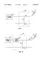
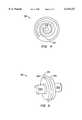
- FIG. 5illustrates a front view of the surge blocking device in accordance with the present invention.
- FIG. 6illustrates an iterative process to determine the inductance of the spiral inductor and the capacitance of the surge blocking device.
- insulating membersDisposed at various locations throughout the housing 220 are insulating members. Preferably, there is a first and a second 226, 228 insulating member.
- the insulating members 226, 228electrically isolates the inner conductor 215 from the housing 220.
- the insulating members 226, 228may be made of a dielectric material such Teflon which has a dielectric constant of approximately 2.3.
- the insulating members 226, 228are typically cylindrically shaped with a center hole.
Landscapes
- Emergency Protection Circuit Devices (AREA)
- Coils Or Transformers For Communication (AREA)
Abstract
Description
L=Z.sub.0 /(12.6*f.sub.c) (1)
C=1/(12.6*f.sub.c *Z.sub.0) (2)
Claims (24)
Priority Applications (2)
| Application Number | Priority Date | Filing Date | Title |
|---|---|---|---|
| US09/309,397US6115227A (en) | 1997-10-14 | 1999-05-07 | Surge suppressor device |
| US09/591,800US6236551B1 (en) | 1997-10-14 | 2000-06-12 | Surge suppressor device |
Applications Claiming Priority (3)
| Application Number | Priority Date | Filing Date | Title |
|---|---|---|---|
| US6209797P | 1997-10-14 | 1997-10-14 | |
| US09/044,216US6061223A (en) | 1997-10-14 | 1998-03-18 | Surge suppressor device |
| US09/309,397US6115227A (en) | 1997-10-14 | 1999-05-07 | Surge suppressor device |
Related Parent Applications (2)
| Application Number | Title | Priority Date | Filing Date |
|---|---|---|---|
| US09/044,216ContinuationUS6061223A (en) | 1997-10-14 | 1998-03-18 | Surge suppressor device |
| US09/062,097ContinuationUS5940159A (en) | 1995-10-13 | 1998-04-17 | Color microdisplays and methods of manufacturing same |
Related Child Applications (1)
| Application Number | Title | Priority Date | Filing Date |
|---|---|---|---|
| US09/591,800ContinuationUS6236551B1 (en) | 1997-10-14 | 2000-06-12 | Surge suppressor device |
Publications (1)
| Publication Number | Publication Date |
|---|---|
| US6115227Atrue US6115227A (en) | 2000-09-05 |
Family
ID=26721295
Family Applications (3)
| Application Number | Title | Priority Date | Filing Date |
|---|---|---|---|
| US09/044,216Expired - LifetimeUS6061223A (en) | 1997-10-14 | 1998-03-18 | Surge suppressor device |
| US09/309,397Expired - LifetimeUS6115227A (en) | 1997-10-14 | 1999-05-07 | Surge suppressor device |
| US09/591,800Expired - LifetimeUS6236551B1 (en) | 1997-10-14 | 2000-06-12 | Surge suppressor device |
Family Applications Before (1)
| Application Number | Title | Priority Date | Filing Date |
|---|---|---|---|
| US09/044,216Expired - LifetimeUS6061223A (en) | 1997-10-14 | 1998-03-18 | Surge suppressor device |
Family Applications After (1)
| Application Number | Title | Priority Date | Filing Date |
|---|---|---|---|
| US09/591,800Expired - LifetimeUS6236551B1 (en) | 1997-10-14 | 2000-06-12 | Surge suppressor device |
Country Status (9)
| Country | Link |
|---|---|
| US (3) | US6061223A (en) |
| EP (1) | EP1023754B1 (en) |
| KR (1) | KR20010015726A (en) |
| CN (1) | CN1275253A (en) |
| AU (1) | AU9115598A (en) |
| CA (1) | CA2305514C (en) |
| DE (1) | DE69820101T2 (en) |
| ES (1) | ES2206985T3 (en) |
| WO (1) | WO1999019957A1 (en) |
Cited By (36)
| Publication number | Priority date | Publication date | Assignee | Title |
|---|---|---|---|---|
| US6236551B1 (en)* | 1997-10-14 | 2001-05-22 | Polyphaser Corporation | Surge suppressor device |
| US20030072121A1 (en)* | 2001-10-12 | 2003-04-17 | Polyphaser Corporation | Rf surge protection device |
| US20030179533A1 (en)* | 2002-03-21 | 2003-09-25 | Polyphaser Corporation | Isolated shield coaxial surge suppressor |
| US20040042149A1 (en)* | 2002-04-15 | 2004-03-04 | Edward Devine | Surge lightning protection device |
| US20040169986A1 (en)* | 2001-06-15 | 2004-09-02 | Kauffman George M. | Protective device |
| US20050141486A1 (en)* | 2003-12-24 | 2005-06-30 | Rod Gilchrist | Method and apparatus for controlling unsolicited messaging |
| US20060146458A1 (en)* | 2005-01-03 | 2006-07-06 | Huberag | Surge suppressor with increased surge current capability |
| US7178083B1 (en)* | 1999-07-13 | 2007-02-13 | Koninklijke Philips Electronics N.V. | Device for scanning an information carrier, method of manufacturing, and information carrier |
| US20070081287A1 (en)* | 2005-10-07 | 2007-04-12 | Andrew Corporation | Multiple Planar Inductor Coaxial Surge Suppressor |
| US20090103226A1 (en)* | 2007-10-18 | 2009-04-23 | Polyphaser Corporation | Surge suppression device having one or more rings |
| US20090109584A1 (en)* | 2007-10-30 | 2009-04-30 | Polyphaser Corporation | Surge protection circuit for passing dc and rf signals |
| US20090284888A1 (en)* | 2008-05-19 | 2009-11-19 | Polyphaser Corporation | Dc and rf pass broadband surge suppressor |
| US20100265625A1 (en)* | 2009-04-17 | 2010-10-21 | John Mezzalingua Associates, Inc. | Coaxial broadband surge protector |
| US20110080683A1 (en)* | 2009-10-02 | 2011-04-07 | Jones Jonathan L | Rf coaxial surge protectors with non-linear protection devices |
| US20110159727A1 (en)* | 2009-12-28 | 2011-06-30 | Matt Howard | Power distribution device |
| US20110235229A1 (en)* | 2010-03-26 | 2011-09-29 | Nguyen Eric H | Ethernet surge protector |
| US8228656B2 (en) | 2007-09-12 | 2012-07-24 | Kauffman George M | Protective device for a radio frequency transmission line |
| EP1808938A3 (en)* | 2006-01-13 | 2012-12-05 | Andrew Corporation | Multiple planar inductive loop surge suppressor |
| US8432693B2 (en) | 2010-05-04 | 2013-04-30 | Transtector Systems, Inc. | High power band pass RF filter having a gas tube for surge suppression |
| US8441795B2 (en) | 2010-05-04 | 2013-05-14 | Transtector Systems, Inc. | High power band pass RF filter having a gas tube for surge suppression |
| US8456789B2 (en) | 2010-12-15 | 2013-06-04 | Andrew Llc | Tunable coaxial surge arrestor |
| US8611062B2 (en) | 2010-05-13 | 2013-12-17 | Transtector Systems, Inc. | Surge current sensor and surge protection system including the same |
| US8730640B2 (en) | 2010-05-11 | 2014-05-20 | Transtector Systems, Inc. | DC pass RF protector having a surge suppression module |
| US8730637B2 (en) | 2010-12-17 | 2014-05-20 | Transtector Systems, Inc. | Surge protection devices that fail as an open circuit |
| US8976500B2 (en) | 2010-05-26 | 2015-03-10 | Transtector Systems, Inc. | DC block RF coaxial devices |
| US9048662B2 (en) | 2012-03-19 | 2015-06-02 | Transtector Systems, Inc. | DC power surge protector |
| US9054514B2 (en) | 2012-02-10 | 2015-06-09 | Transtector Systems, Inc. | Reduced let through voltage transient protection or suppression circuit |
| US9124093B2 (en) | 2012-09-21 | 2015-09-01 | Transtector Systems, Inc. | Rail surge voltage protector with fail disconnect |
| US9190837B2 (en) | 2012-05-03 | 2015-11-17 | Transtector Systems, Inc. | Rigid flex electromagnetic pulse protection device |
| US9924609B2 (en) | 2015-07-24 | 2018-03-20 | Transtector Systems, Inc. | Modular protection cabinet with flexible backplane |
| US9991697B1 (en) | 2016-12-06 | 2018-06-05 | Transtector Systems, Inc. | Fail open or fail short surge protector |
| US10129993B2 (en) | 2015-06-09 | 2018-11-13 | Transtector Systems, Inc. | Sealed enclosure for protecting electronics |
| US10193335B2 (en) | 2015-10-27 | 2019-01-29 | Transtector Systems, Inc. | Radio frequency surge protector with matched piston-cylinder cavity shape |
| US10356928B2 (en) | 2015-07-24 | 2019-07-16 | Transtector Systems, Inc. | Modular protection cabinet with flexible backplane |
| US10588236B2 (en) | 2015-07-24 | 2020-03-10 | Transtector Systems, Inc. | Modular protection cabinet with flexible backplane |
| US20230163537A1 (en)* | 2021-11-22 | 2023-05-25 | Corning Optical Communications Rf Llc | Devices, assemblies, and methods for terminating coaxial radiofrequency ports |
Families Citing this family (36)
| Publication number | Priority date | Publication date | Assignee | Title |
|---|---|---|---|---|
| US6452773B1 (en) | 2000-03-21 | 2002-09-17 | Andrew Corporation | Broadband shorted stub surge protector |
| US6636407B1 (en) | 2000-09-13 | 2003-10-21 | Andrew Corporation | Broadband surge protector for RF/DC carrying conductor |
| DE10102201C2 (en)* | 2001-01-18 | 2003-05-08 | Epcos Ag | Electrical switching module, switching module arrangement and use of the switching module and the switching module arrangement |
| US20050059371A1 (en)* | 2001-09-28 | 2005-03-17 | Christian Block | Circuit arrangement, switching module comprising said circuit arrangement and use of switching module |
| US7492565B2 (en)* | 2001-09-28 | 2009-02-17 | Epcos Ag | Bandpass filter electrostatic discharge protection device |
| US7688595B2 (en)* | 2002-03-13 | 2010-03-30 | Pioneer Energy Products, Llc | Shielded cable entry ports and assemblies |
| DE10212365C1 (en)* | 2002-03-20 | 2003-08-21 | Rosenberger Hochfrequenztech | Electrical coaxial connector with overvoltage protection provided by capacitor with opposing capacitor plates coupled to inner conductor on input and output sides and axial coil coupled to outer conductor |
| KR100653440B1 (en)* | 2002-08-03 | 2006-12-01 | 주식회사 케이엠더블유 | Bias-tee device and its center conductor device |
| DE10246098A1 (en) | 2002-10-02 | 2004-04-22 | Epcos Ag | circuitry |
| US7397646B2 (en)* | 2004-11-30 | 2008-07-08 | Tdk Corporation | Surge absorption circuit |
| US7094104B1 (en) | 2005-05-04 | 2006-08-22 | Andrew Corporation | In-line coaxial circuit assembly |
| JP4715371B2 (en)* | 2005-07-29 | 2011-07-06 | Tdk株式会社 | Surge absorbing element and surge absorbing circuit |
| US7349191B2 (en)* | 2005-09-01 | 2008-03-25 | Andrew Corporation | Offset planar coil coaxial surge suppressor |
| JP4434121B2 (en)* | 2005-09-30 | 2010-03-17 | Tdk株式会社 | connector |
| US20070097583A1 (en)* | 2005-10-31 | 2007-05-03 | Andrew Corporation | Tuned Coil Coaxial Surge Suppressor |
| US7583489B2 (en)* | 2006-05-22 | 2009-09-01 | Andrew Llc | Tungsten shorting stub and method of manufacture |
| US8174132B2 (en)* | 2007-01-17 | 2012-05-08 | Andrew Llc | Folded surface capacitor in-line assembly |
| DE102007030157A1 (en) | 2007-06-27 | 2009-01-08 | Phoenix Contact Gmbh & Co. Kg | Tunable λ / 4 filter assembly |
| US8570178B2 (en)* | 2007-09-24 | 2013-10-29 | Ppc Broadband, Inc. | Coaxial cable connector with internal floating ground circuitry and method of use thereof |
| US8773255B2 (en) | 2007-09-24 | 2014-07-08 | Ppc Broadband, Inc. | Status sensing and reporting interface |
| US7623332B2 (en)* | 2008-01-31 | 2009-11-24 | Commscope, Inc. Of North Carolina | Low bypass fine arrestor |
| US8248740B2 (en)* | 2008-09-19 | 2012-08-21 | Advanced Fusion Systems, Llc | High speed current shunt |
| US8303334B2 (en)* | 2008-11-17 | 2012-11-06 | John Mezzalingua Associates, Inc. | Embedded coupler device and method of use thereof |
| US8414326B2 (en)* | 2008-11-17 | 2013-04-09 | Rochester Institute Of Technology | Internal coaxial cable connector integrated circuit and method of use thereof |
| US8419464B2 (en)* | 2008-11-17 | 2013-04-16 | Ppc Broadband, Inc. | Coaxial connector with integrated molded substrate and method of use thereof |
| US8376774B2 (en)* | 2008-11-17 | 2013-02-19 | Rochester Institute Of Technology | Power extracting device and method of use thereof |
| US8259430B2 (en)* | 2009-09-25 | 2012-09-04 | John Mezzalingua Associates, Inc. | Surge protection device for isolating premise devices |
| US8462479B2 (en)* | 2009-09-25 | 2013-06-11 | Ppc Broadband, Inc. | Surge protection device with improved response time |
| US8618944B2 (en)* | 2009-12-03 | 2013-12-31 | Ppc Broadband, Inc. | Coaxial cable connector parameter monitoring system |
| US8604936B2 (en) | 2010-12-13 | 2013-12-10 | Ppc Broadband, Inc. | Coaxial cable connector, system and method of use thereof |
| US8810989B2 (en)* | 2011-04-18 | 2014-08-19 | Alcatel Lucent | DC pass filter using flat inductor in cavity |
| US8939796B2 (en)* | 2011-10-11 | 2015-01-27 | Commscope, Inc. Of North Carolina | Surge protector components having a plurality of spark gap members between a central conductor and an outer housing |
| US8858262B2 (en)* | 2012-12-04 | 2014-10-14 | Genesis Technology Usa, Inc. | F-connector with integrated surge protection |
| CN104953576B (en)* | 2015-05-15 | 2017-12-08 | 湖南中普技术股份有限公司 | A kind of integrated form radio frequency lightning protection device and integrated lightening arresting method |
| FR3061813B1 (en)* | 2017-01-06 | 2021-09-10 | Citel | INTEGRATED OVERVOLTAGE PROTECTION COMPONENT, ESPECIALLY FOR A COAXIAL CABLE SYSTEM |
| KR102715761B1 (en)* | 2023-04-10 | 2024-10-11 | 한국기술교육대학교 산학협력단 | Method for calculating proper capacity of surge protection device for energy storage system |
Citations (9)
| Publication number | Priority date | Publication date | Assignee | Title |
|---|---|---|---|---|
| US4047120A (en)* | 1976-07-15 | 1977-09-06 | The United States Of America As Represented By The Secretary Of The Navy | Transient suppression circuit for push-pull switching amplifiers |
| US4262317A (en)* | 1979-03-22 | 1981-04-14 | Reliable Electric Company | Line protector for a communications circuit |
| US4384331A (en)* | 1979-04-23 | 1983-05-17 | Nissan Motor Company, Limited | Noise suppressor for vehicle digital system |
| US4563720A (en)* | 1984-04-17 | 1986-01-07 | General Semiconductor Industries, Inc. | Hybrid AC line transient suppressor |
| US4689713A (en)* | 1985-06-12 | 1987-08-25 | Les Cables De Lyon | High voltage surge protection for electrical power line |
| US4984146A (en)* | 1990-03-27 | 1991-01-08 | International Business Machines Corporation | Suppression of radiated EMI for power supplies |
| US5053910A (en)* | 1989-10-16 | 1991-10-01 | Perma Power Electronics, Inc. | Surge suppressor for coaxial transmission line |
| US5321573A (en)* | 1992-07-16 | 1994-06-14 | Dale Electronics, Inc. | Monolythic surge suppressor |
| US5617284A (en)* | 1994-08-05 | 1997-04-01 | Paradise; Rick | Power surge protection apparatus and method |
Family Cites Families (11)
| Publication number | Priority date | Publication date | Assignee | Title |
|---|---|---|---|---|
| US3845358A (en)* | 1973-06-29 | 1974-10-29 | Gen Electric | Integrated polycrystalline varistor surge protective device for high frequency applications |
| US4359764A (en)* | 1980-04-08 | 1982-11-16 | Block Roger R | Connector for electromagnetic impulse suppression |
| US4409637A (en)* | 1980-04-08 | 1983-10-11 | Block Roger R | Connector for electromagnetic impulse suppression |
| US4554608A (en)* | 1982-11-15 | 1985-11-19 | Block Roger R | Connector for electromagnetic impulse suppression |
| JPH0727796B2 (en)* | 1986-04-28 | 1995-03-29 | 有限会社パテントプロモートセンター | Overvoltage absorption element |
| US5057964A (en)* | 1986-12-17 | 1991-10-15 | Northern Telecom Limited | Surge protector for telecommunications terminals |
| US4985800A (en)* | 1989-10-30 | 1991-01-15 | Feldman Nathan W | Lighting protection apparatus for RF equipment and the like |
| US5122921A (en)* | 1990-04-26 | 1992-06-16 | Industrial Communication Engineers, Ltd. | Device for electromagnetic static and voltage suppression |
| ATE198390T1 (en)* | 1993-10-07 | 2001-01-15 | Andrew Corp | OVERVOLTAGE PROTECTION |
| US5667298A (en)* | 1996-01-16 | 1997-09-16 | Cedarapids, Inc. | Portable concrete mixer with weigh/surge systems |
| US6061223A (en)* | 1997-10-14 | 2000-05-09 | Polyphaser Corporation | Surge suppressor device |
- 1998
- 1998-03-18USUS09/044,216patent/US6061223A/ennot_activeExpired - Lifetime
- 1998-08-20EPEP98943331Apatent/EP1023754B1/ennot_activeExpired - Lifetime
- 1998-08-20AUAU91155/98Apatent/AU9115598A/ennot_activeAbandoned
- 1998-08-20ESES98943331Tpatent/ES2206985T3/ennot_activeExpired - Lifetime
- 1998-08-20WOPCT/US1998/017461patent/WO1999019957A1/enactiveIP Right Grant
- 1998-08-20CACA002305514Apatent/CA2305514C/ennot_activeExpired - Lifetime
- 1998-08-20DEDE69820101Tpatent/DE69820101T2/ennot_activeExpired - Lifetime
- 1998-08-20KRKR1020007003854Apatent/KR20010015726A/ennot_activeWithdrawn
- 1998-08-20CNCN98810091.6Apatent/CN1275253A/enactivePending
- 1999
- 1999-05-07USUS09/309,397patent/US6115227A/ennot_activeExpired - Lifetime
- 2000
- 2000-06-12USUS09/591,800patent/US6236551B1/ennot_activeExpired - Lifetime
Patent Citations (9)
| Publication number | Priority date | Publication date | Assignee | Title |
|---|---|---|---|---|
| US4047120A (en)* | 1976-07-15 | 1977-09-06 | The United States Of America As Represented By The Secretary Of The Navy | Transient suppression circuit for push-pull switching amplifiers |
| US4262317A (en)* | 1979-03-22 | 1981-04-14 | Reliable Electric Company | Line protector for a communications circuit |
| US4384331A (en)* | 1979-04-23 | 1983-05-17 | Nissan Motor Company, Limited | Noise suppressor for vehicle digital system |
| US4563720A (en)* | 1984-04-17 | 1986-01-07 | General Semiconductor Industries, Inc. | Hybrid AC line transient suppressor |
| US4689713A (en)* | 1985-06-12 | 1987-08-25 | Les Cables De Lyon | High voltage surge protection for electrical power line |
| US5053910A (en)* | 1989-10-16 | 1991-10-01 | Perma Power Electronics, Inc. | Surge suppressor for coaxial transmission line |
| US4984146A (en)* | 1990-03-27 | 1991-01-08 | International Business Machines Corporation | Suppression of radiated EMI for power supplies |
| US5321573A (en)* | 1992-07-16 | 1994-06-14 | Dale Electronics, Inc. | Monolythic surge suppressor |
| US5617284A (en)* | 1994-08-05 | 1997-04-01 | Paradise; Rick | Power surge protection apparatus and method |
Cited By (58)
| Publication number | Priority date | Publication date | Assignee | Title |
|---|---|---|---|---|
| US6236551B1 (en)* | 1997-10-14 | 2001-05-22 | Polyphaser Corporation | Surge suppressor device |
| US7178083B1 (en)* | 1999-07-13 | 2007-02-13 | Koninklijke Philips Electronics N.V. | Device for scanning an information carrier, method of manufacturing, and information carrier |
| US7440253B2 (en) | 2001-06-15 | 2008-10-21 | Kauffman George M | Protective device |
| US20080043396A1 (en)* | 2001-06-15 | 2008-02-21 | Kauffman George M | Protective device |
| US20040169986A1 (en)* | 2001-06-15 | 2004-09-02 | Kauffman George M. | Protective device |
| US7609502B2 (en) | 2001-06-15 | 2009-10-27 | Kauffman George M | Protective device |
| US20080151461A1 (en)* | 2001-06-15 | 2008-06-26 | Kauffman George M | Protective device |
| US7564669B2 (en) | 2001-06-15 | 2009-07-21 | Kauffman George M | Protective device |
| US20030072121A1 (en)* | 2001-10-12 | 2003-04-17 | Polyphaser Corporation | Rf surge protection device |
| US6785110B2 (en) | 2001-10-12 | 2004-08-31 | Polyphaser Corporation | Rf surge protection device |
| US20030179533A1 (en)* | 2002-03-21 | 2003-09-25 | Polyphaser Corporation | Isolated shield coaxial surge suppressor |
| US6975496B2 (en)* | 2002-03-21 | 2005-12-13 | Polyphaser Corporation | Isolated shield coaxial surge suppressor |
| US20040042149A1 (en)* | 2002-04-15 | 2004-03-04 | Edward Devine | Surge lightning protection device |
| US7123463B2 (en) | 2002-04-15 | 2006-10-17 | Andrew Corporation | Surge lightning protection device |
| US20050141486A1 (en)* | 2003-12-24 | 2005-06-30 | Rod Gilchrist | Method and apparatus for controlling unsolicited messaging |
| US7170728B2 (en) | 2005-01-03 | 2007-01-30 | Huber+Suhner Ag | Surge suppressor with increased surge current capability |
| US20060146458A1 (en)* | 2005-01-03 | 2006-07-06 | Huberag | Surge suppressor with increased surge current capability |
| US7324318B2 (en) | 2005-10-07 | 2008-01-29 | Andrew Corporation | Multiple planar inductor coaxial surge suppressor |
| EP1772931A3 (en)* | 2005-10-07 | 2008-05-21 | Andrew Corporation | Multiple planar inductor coaxial surge suppressor |
| JP2007110716A (en)* | 2005-10-07 | 2007-04-26 | Andrew Corp | Multiple planar inductor coaxial surge suppressor |
| US20070081287A1 (en)* | 2005-10-07 | 2007-04-12 | Andrew Corporation | Multiple Planar Inductor Coaxial Surge Suppressor |
| EP1808938A3 (en)* | 2006-01-13 | 2012-12-05 | Andrew Corporation | Multiple planar inductive loop surge suppressor |
| US8228656B2 (en) | 2007-09-12 | 2012-07-24 | Kauffman George M | Protective device for a radio frequency transmission line |
| US20090103226A1 (en)* | 2007-10-18 | 2009-04-23 | Polyphaser Corporation | Surge suppression device having one or more rings |
| US8553386B2 (en) | 2007-10-18 | 2013-10-08 | Transtector Systems, Inc. | Surge suppression device having one or more rings |
| WO2009052517A3 (en)* | 2007-10-18 | 2009-08-13 | Polyphaser Corp | Surge suppression device having one or more rings |
| US8027136B2 (en) | 2007-10-18 | 2011-09-27 | Transtector Systems, Inc. | Surge suppression device having one or more rings |
| US20110141646A1 (en)* | 2007-10-30 | 2011-06-16 | Jones Jonathan L | Surge protection circuit for passing dc and rf signals |
| US8179656B2 (en) | 2007-10-30 | 2012-05-15 | Transtector Systems, Inc. | Surge protection circuit for passing DC and RF signals |
| US7944670B2 (en) | 2007-10-30 | 2011-05-17 | Transtector Systems, Inc. | Surge protection circuit for passing DC and RF signals |
| US20090109584A1 (en)* | 2007-10-30 | 2009-04-30 | Polyphaser Corporation | Surge protection circuit for passing dc and rf signals |
| US8599528B2 (en) | 2008-05-19 | 2013-12-03 | Transtector Systems, Inc. | DC and RF pass broadband surge suppressor |
| US20090284888A1 (en)* | 2008-05-19 | 2009-11-19 | Polyphaser Corporation | Dc and rf pass broadband surge suppressor |
| US20100265625A1 (en)* | 2009-04-17 | 2010-10-21 | John Mezzalingua Associates, Inc. | Coaxial broadband surge protector |
| US8125752B2 (en) | 2009-04-17 | 2012-02-28 | John Mezzalingua Associates, Inc. | Coaxial broadband surge protector |
| US8456791B2 (en) | 2009-10-02 | 2013-06-04 | Transtector Systems, Inc. | RF coaxial surge protectors with non-linear protection devices |
| US20110080683A1 (en)* | 2009-10-02 | 2011-04-07 | Jones Jonathan L | Rf coaxial surge protectors with non-linear protection devices |
| US20110159727A1 (en)* | 2009-12-28 | 2011-06-30 | Matt Howard | Power distribution device |
| US8400760B2 (en) | 2009-12-28 | 2013-03-19 | Transtector Systems, Inc. | Power distribution device |
| US20110235229A1 (en)* | 2010-03-26 | 2011-09-29 | Nguyen Eric H | Ethernet surge protector |
| US8432693B2 (en) | 2010-05-04 | 2013-04-30 | Transtector Systems, Inc. | High power band pass RF filter having a gas tube for surge suppression |
| US8441795B2 (en) | 2010-05-04 | 2013-05-14 | Transtector Systems, Inc. | High power band pass RF filter having a gas tube for surge suppression |
| US8730640B2 (en) | 2010-05-11 | 2014-05-20 | Transtector Systems, Inc. | DC pass RF protector having a surge suppression module |
| US8611062B2 (en) | 2010-05-13 | 2013-12-17 | Transtector Systems, Inc. | Surge current sensor and surge protection system including the same |
| US8976500B2 (en) | 2010-05-26 | 2015-03-10 | Transtector Systems, Inc. | DC block RF coaxial devices |
| US8456789B2 (en) | 2010-12-15 | 2013-06-04 | Andrew Llc | Tunable coaxial surge arrestor |
| US8730637B2 (en) | 2010-12-17 | 2014-05-20 | Transtector Systems, Inc. | Surge protection devices that fail as an open circuit |
| US9054514B2 (en) | 2012-02-10 | 2015-06-09 | Transtector Systems, Inc. | Reduced let through voltage transient protection or suppression circuit |
| US9048662B2 (en) | 2012-03-19 | 2015-06-02 | Transtector Systems, Inc. | DC power surge protector |
| US9190837B2 (en) | 2012-05-03 | 2015-11-17 | Transtector Systems, Inc. | Rigid flex electromagnetic pulse protection device |
| US9124093B2 (en) | 2012-09-21 | 2015-09-01 | Transtector Systems, Inc. | Rail surge voltage protector with fail disconnect |
| US10129993B2 (en) | 2015-06-09 | 2018-11-13 | Transtector Systems, Inc. | Sealed enclosure for protecting electronics |
| US9924609B2 (en) | 2015-07-24 | 2018-03-20 | Transtector Systems, Inc. | Modular protection cabinet with flexible backplane |
| US10356928B2 (en) | 2015-07-24 | 2019-07-16 | Transtector Systems, Inc. | Modular protection cabinet with flexible backplane |
| US10588236B2 (en) | 2015-07-24 | 2020-03-10 | Transtector Systems, Inc. | Modular protection cabinet with flexible backplane |
| US10193335B2 (en) | 2015-10-27 | 2019-01-29 | Transtector Systems, Inc. | Radio frequency surge protector with matched piston-cylinder cavity shape |
| US9991697B1 (en) | 2016-12-06 | 2018-06-05 | Transtector Systems, Inc. | Fail open or fail short surge protector |
| US20230163537A1 (en)* | 2021-11-22 | 2023-05-25 | Corning Optical Communications Rf Llc | Devices, assemblies, and methods for terminating coaxial radiofrequency ports |
Also Published As
| Publication number | Publication date |
|---|---|
| EP1023754A1 (en) | 2000-08-02 |
| EP1023754A4 (en) | 2002-03-13 |
| CA2305514C (en) | 2005-04-12 |
| DE69820101D1 (en) | 2004-01-08 |
| KR20010015726A (en) | 2001-02-26 |
| WO1999019957A1 (en) | 1999-04-22 |
| US6061223A (en) | 2000-05-09 |
| ES2206985T3 (en) | 2004-05-16 |
| DE69820101T2 (en) | 2004-05-27 |
| CN1275253A (en) | 2000-11-29 |
| CA2305514A1 (en) | 1999-04-22 |
| EP1023754B1 (en) | 2003-11-26 |
| US6236551B1 (en) | 2001-05-22 |
| AU9115598A (en) | 1999-05-03 |
Similar Documents
| Publication | Publication Date | Title |
|---|---|---|
| US6115227A (en) | Surge suppressor device | |
| EP2569839B1 (en) | Dc pass rf protector having a surge suppression module | |
| US8456791B2 (en) | RF coaxial surge protectors with non-linear protection devices | |
| Judd et al. | Broadband couplers for UHF detection of partial discharge in gas-insulated substations | |
| US8976500B2 (en) | DC block RF coaxial devices | |
| US7092230B2 (en) | Interference filter and lightning conductor device | |
| US4987391A (en) | Antenna cable ground isolator | |
| US6950294B2 (en) | Surge protection filter and lightning conductor system | |
| US8063725B2 (en) | Form C relay and package using same | |
| US7126356B2 (en) | Radiation detector for electrostatic discharge | |
| US7180392B2 (en) | Coaxial DC block | |
| JP3598251B2 (en) | Method and apparatus for reducing ESD induced EMI radiating from I/O connector openings - Patents.com | |
| US20090251840A1 (en) | Quarter wave stub surge suppressor with coupled pins | |
| Sinai et al. | Multi-Physical sensor fusion approach for partial discharge detection on medium voltage cable connectors | |
| JP2002022790A (en) | Partial discharge detector for gas insulated equipment | |
| US9601444B2 (en) | Cable mounted modularized signal conditioning apparatus system | |
| Szymczak | PIFA antenna for partial discharge detection in power transformers | |
| US5397980A (en) | Current probe calibration fixture | |
| JPH0297107A (en) | Noise generation preventing circuit for ic element | |
| Bryson | Design of high isolation duplexers and a new antenna for duplex systems | |
| JP2011169731A (en) | Cable for measuring noise, and noise measuring device | |
| JP2003259547A (en) | Surge absorber |
Legal Events
| Date | Code | Title | Description |
|---|---|---|---|
| STCF | Information on status: patent grant | Free format text:PATENTED CASE | |
| FEPP | Fee payment procedure | Free format text:PAYER NUMBER DE-ASSIGNED (ORIGINAL EVENT CODE: RMPN); ENTITY STATUS OF PATENT OWNER: LARGE ENTITY | |
| FPAY | Fee payment | Year of fee payment:4 | |
| FEPP | Fee payment procedure | Free format text:PAYOR NUMBER ASSIGNED (ORIGINAL EVENT CODE: ASPN); ENTITY STATUS OF PATENT OWNER: LARGE ENTITY | |
| FPAY | Fee payment | Year of fee payment:8 | |
| AS | Assignment | Owner name:TRANSTECTOR SYSTEMS, INC., IDAHO Free format text:MERGER;ASSIGNOR:POLYPHASER CORPORATION;REEL/FRAME:024741/0453 Effective date:20090724 | |
| FPAY | Fee payment | Year of fee payment:12 | |
| AS | Assignment | Owner name:ANTARES CAPITAL LP, AS ADMINISTRATIVE AGENT, ILLIN Free format text:SECURITY INTEREST;ASSIGNOR:TRANSTECTOR SYSTEMS, INC.;REEL/FRAME:042191/0680 Effective date:20170501 Owner name:ANTARES CAPITAL LP, AS ADMINISTRATIVE AGENT, ILLIN Free format text:SECURITY INTEREST;ASSIGNOR:TRANSTECTOR SYSTEMS, INC.;REEL/FRAME:042192/0095 Effective date:20170501 | |
| AS | Assignment | Owner name:INFINITE ELECTRONICS INTERNATIONAL, INC., CALIFORNIA Free format text:PATENT RELEASE;ASSIGNOR:ANTARES CAPITAL LP, AS ADMINISTRATIVE AGENT;REEL/FRAME:055488/0714 Effective date:20210302 Owner name:INFINITE ELECTRONICS INTERNATIONAL, INC., CALIFORNIA Free format text:PATENT RELEASE 2L;ASSIGNOR:ANTARES CAPITAL LP, AS ADMINISTRATIVE AGENT;REEL/FRAME:055489/0142 Effective date:20210302 |