US6115050A - Object-based anti-aliasing - Google Patents
Object-based anti-aliasingDownload PDFInfo
- Publication number
- US6115050A US6115050AUS09/057,327US5732798AUS6115050AUS 6115050 AUS6115050 AUS 6115050AUS 5732798 AUS5732798 AUS 5732798AUS 6115050 AUS6115050 AUS 6115050A
- Authority
- US
- United States
- Prior art keywords
- polygon
- edge
- aliasing
- polygons
- visible
- Prior art date
- Legal status (The legal status is an assumption and is not a legal conclusion. Google has not performed a legal analysis and makes no representation as to the accuracy of the status listed.)
- Expired - Lifetime
Links
Images


Classifications
- G—PHYSICS
- G06—COMPUTING OR CALCULATING; COUNTING
- G06T—IMAGE DATA PROCESSING OR GENERATION, IN GENERAL
- G06T15/00—3D [Three Dimensional] image rendering
- G06T15/50—Lighting effects
- G06T15/503—Blending, e.g. for anti-aliasing
Definitions
- the present inventionrelates generally to computer graphics rendering, and more particularly to anti-aliasing of the edges of objects represented in computer generated images.
- Graphics rendering systemscreate images of objects which are combined in a visual scene.
- An objectis a computer readable specification of appearance attributes which, when used to create an image, has the appearance of physical substance.
- a sceneis a collection of objects distributed around an area to be represented in an image.
- an imageis constructed based on the location and orientation of two dimensional objects in a scene.
- three dimensional objectsare placed in a three dimensional scene with a three dimensional coordinate system.
- a camerais defined by at least a location and a direction of view relative to a scene.
- Renderingis the process of creating an image based on the objects which would be visible to a camera viewing a scene if it were real, and placing this image in memory, typically a frame buffer.
- the imageis composed of an array of picture elements, or pixels, which each exhibit a color.
- the imageis displayed, typically on a computer monitor, while a later image is being constructed.
- the part of the rendering system which interprets object data to determine what the scene looks likeis referred to as the rendering pipeline.
- High speed rendering systemstypically rely on combinations of simple polygons, referred to as primitives, to build more complex objects.
- the rendering pipeline of such a systemis generally optimized to render primitives into the frame buffer quickly.
- Trianglesare commonly used as primitives, since objects of arbitrary complexity may be composed of triangles. This is illustrated in FIG. 1.
- the discrete pixels of an image in a frame bufferare comparable to samples of a continuous image.
- a well known phenomenon associated with discrete sampling of continuous valuesis aliasing.
- aliasingis most often encountered in the form of straight lines which have a jagged or stair-stepped appearance, as illustrated in FIG. 2.
- the edges of primitives (such as triangles) rendered to an imagemay exhibit this pattern, which is especially noticeable where there is high contrast between the color of a foreground primitive and the color of the background. This aliasing of primitive edges is generally undesirable, and steps are taken to reduce the effect of it.
- a pixel which represents an area of a scene containing an edge of high color contrast in a computer generated imagewill generally be colored according to whichever color happens to coincide with the centroid of the pixel. This is illustrated in FIG. 3, where a pixel is shown representing an area which is partly red and partly blue. The pixel is given the color red, because the centroid of the pixel falls on the red primitive. A more realistic image, and one without noticeable aliasing effects, would be obtained if the pixel were colored with both red and blue, in the proportion each is present in the area represented by the pixel. This blending of colors is at the heart of most schemes to reduce the effects of aliasing. Efforts to reduce aliasing in the field of computer graphics are referred to as anti-aliasing.
- One method of performing anti-aliasingis to determine colors for a number of samples within the area represented by each pixel. Each of these sub-samples is at a slightly different location, and the sub-samples are averaged together to determine a final color for the pixel. This method reduces aliasing considerably, but at the expense of increasing the amount of calculation, and time, required for rendering each pixel. The time expense is so large that this solution is not generally used for real-time rendering systems.
- a solution which is feasible for real-time renderingis to blend the color of each pixel in an image with the colors of surrounding pixels. This is, in effect, a low-pass filter applied to the initial image determined by the rendering pipeline. The added amount of calculation is much less than for the sub-sampling solution, but the results are poor. The entire image is blurred, and appears to be out of focus.
- a silhouette edgeis the visible perimeter of an object. Sharp contrasts (and therefore areas of noticeable aliasing) are generally most likely to occur at silhouette edges. Finding the portions of an image which correspond to object silhouette edges is not trivial.
- One method of finding these edgesis to use a buffer which holds one bit per pixel of the finished image. The buffer is set to all zeros, then as each object is rendered the state of the bits in the buffer corresponding to the drawn pixels are changed. When all objects have been rendered, the bits of this buffer will have gradients from one to zero or from zero to one in areas corresponding to the silhouette edges of many of the objects. The corresponding areas in the image are then subjected to low-pass filtering.
- This methoduses a lot of memory for the buffer, does not always catch all of the object silhouette edges and generates a lot of false edges.
- the present inventionis a computer apparatus and method for anti-aliasing the silhouette edges of objects rendered by a rendering pipeline.
- the objectsare composed of primitives, such as triangles, each of which has edges which may be a silhouette edge of the object under particular circumstances.
- information concerning which edges may be silhouette edges in particular circumstancesis encoded with the object.
- the rendering pipelinerenders an image in a first pass, information is collected concerning how many times some of the potential silhouette edges are drawn.
- a second passbegins. In this pass, the rendering pipeline uses the information about the edges which was encoded with each object, in conjunction with the information about the number of times particular edges were drawn, to determine which edges in the image lie at the silhouette edge of an object.
- silhouette edgesare anti-aliased, providing a clear image without significant aliasing effects, through the use of a method which does not require much additional time or memory.
- FIG. 1illustrates how complex objects may be constructed from triangles 108.
- FIG. 2illustrates aliasing effects on a line displayed at low resolution.
- FIG. 3illustrates how color is assigned to a pixel which represents an edge of high color contrast.
- FIG. 4illustrates a few ways in which triangles 108 may be connected to form a strip 104.
- FIG. 5illustrates the sequence of registers used by the processor 168 in interpreting a strip 104.
- FIG. 6illustrates a few ways that triangles 108 may be connected to form a fan 106.
- FIG. 7illustrates the sequence of registers used by the processor 168 in interpreting a fan 106.
- FIG. 8illustrates a sphere 701 composed of strips 104 and fans 106.
- FIG. 9illustrates a typical strip 104 and fan 106, showing the association of edges to vertices 110.
- FIG. 10illustrates the edge indices for a multi-strip object 116.
- FIG. 11ais part of a flowchart illustrating the first pass of the processor 168.
- FIG. 11bis part of a flowchart illustrating the first pass of the processor 168.
- FIG. 11cis part of a flowchart illustrating the second pass of the processor 168.
- FIG. 11dis part of a flowchart illustrating the second pass of the processor 168.
- FIG. 12illustrates an embodiment in which processor 168 controls culling module 164 and polygon rendering module 166.
- FIG. 13is a flowchart illustrating a method of anti-aliasing an edge of a triangle 108.
- FIG. 14illustrates the anti-aliasing method.
- the present inventionmay be implemented as functional components consisting of hardware, software, firmware or some combination thereof.
- the inventionis implemented in a three dimensional graphics rendering system in which the basic primitives are triangles 108. This is for illustrative purposes only, and in other embodiments the invention may be part of other types of graphics systems, including for example a two dimensional graphics rendering system, and primitives of other shapes may be used.
- a complex object to be renderedis composed of contiguous triangles 108
- a great deal of redundancy in the specification of vertices 110might occur, with the coordinates for some points being repeatedly given to the rendering pipeline.
- a number of multi-primitive shapesare composed in such a way that the amount of redundancy in their specification may be reduced.
- strips 104 and fans 106Two of the most common higher-level primitives used in three dimensional object modeling are strips 104 and fans 106. Both strips 104 and fans 106 are used by the graphics rendering system of the illustrative embodiment. Some examples of strips 104 are shown in FIG. 4.
- the vertices 110 of each strip 104are numbered in the order they are given in the definition of a strip 104 (11 through 16).
- a strip 104is specified to the rendering pipeline as an instruction to draw a strip 104, a series of vertices 110 with associated channel information, and an instruction to stop rendering the strip 104.
- a channelis a field of information for which each vertex 110 has an associated value.
- Examples of typical channels associated with vertices 110include the X, Y, and Z coordinates of each vertex 110, color values, opacity values, and texture coordinates.
- the first triangle 108is specified by the first three vertices 110 (e.g. 11, 12, and 13), with each subsequent triangle 108 in the strip 104 being specified by one more vertex 110.
- a rendering pipelineuses three registers. Initially, at time step 0, all three registers are empty. As each vertex 110 in list 404 is read into register 403, the old contents of register 403 are moved to register 402, and the old contents of register 402 are moved to register 401.
- FIG. 6illustrates fans 106 constructed from triangles 108.
- the most notable feature of a fan 106is the single vertex 110 shared by all triangles 108 which make up the fan 106.
- a fan 106like a strip 104, only requires one vertex 110 to be specified in order to define a new triangle 108, after the first triangle 108 is specified.
- Three registers, illustrated in FIG. 7,are used by the rendering pipeline to interpret the list 604 of vertices 110 making up a fan 106.
- the first vertex 110 of list 604is the vertex 110 shared among all triangles 108 of fan 106.
- this vertex 110goes into register 601 and is not changed until the entire fan 106 has been processed.
- Each subsequent vertex 110is read into register 603, with the old contents of register 603 replacing the contents of register 602.
- the first triangle 108is specified by the vertices 110 of the registers, as in the case of the strip 104.
- a new triangle 108 of the fan 106is specified by the contents of the three registers (601-603).
- Time steps 0-6illustrate the construction of a four triangle 108 fan 106. Because the vertex 110 in register 601 does not change, each triangle 108 of fan 106 shares the first vertex 110 of the list.
- FIG. 8illustrates a sphere 701 constructed of strips 104 and fans 106.
- the poles of sphere 701are constructed of fans 106, with lateral strips 104 making up the rest of it.
- a Z bufferis a buffer which is large enough to contain a single Z coordinate value for every pixel of an image.
- the rendering pipelinedraws a pixel to the image, it also records the Z value of the point which is represented by that pixel in the Z buffer location associated with the pixel. Before any pixel is drawn to the image, however, the Z value of the point which is represented by that pixel is compared to the current Z value in the Z buffer location for that pixel.
- the new pixel to be drawnrepresents a point on a primitive which is closer to the camera, and therefore has a smaller Z value
- the pixelis drawn and the Z-buffer is updated with the smaller Z value. Otherwise, the point on the primitive being rendered is obscured by a closer object, and is therefore not drawn.
- Z bufferingSeveral implementations of Z buffering are known in the art, including the use of the inverse of Z in place of the Z value in the buffer.
- Z-bufferingdetects obscured points on primitives before they are rendered to an image, but after the rendering pipeline has completed a lot of calculation. When a point is not drawn because it is obscured, the calculation does not lead to anything being added to the image. Some of this calculation is necessary, but in some cases entire primitives may be determined to be hidden even before Z buffering is applied. In FIG. 8, approximately half of the triangles 108 making up sphere 701 are obscured by the other half of the triangles 108. The Z buffering technique described above would result in these triangles 108 being properly obscured, but a substantial amount of calculation would be performed on each of these obscured triangles 108 in order to determine which are shown.
- Sphere 701is a closed object, meaning that only the outside is viewable, and that only one side of each primitive making it up is visible. Because sphere 701 is a closed object, each triangle 108 making it up may be considered to have an in side and an out side, where only the out sides are ever viewed by an exterior camera. Those triangles 108 which are obscured in the view of sphere 701 are all ones which have their in sides facing the camera. For any closed object, planar primitives which have their in sides facing the camera are obscured, and are called back-facing. The triangles 108 which have their out sides facing the camera, and which are not necessarily obscured, are called front-facing.
- Back-face cullingis the technique of differentiating between triangles 108 facing the camera and triangles 108 facing away from the camera. By determining that a primitive which is part of a closed object is facing away from a camera which is outside the closed object, it is known that the primitive need not be drawn and further calculation related to that primitive can be avoided. If the camera is inside a closed object, then front facing primitives would be culled, and the back-facing primitives would be rendered.
- back-face cullingis implemented by computing the area of the rendered image of each triangle 108 as the cross product of the X, Y projections of two of the triangle 108 sides.
- the sign of the areaindicates whether the triangle 108 will be rendered clockwise or counter-clockwise in the image. If the sign of the area indicates that the image of triangle 108 is clockwise, but the triangle 108 is specified as being a counter-clockwise triangle 108, or if the sign indicates that the image is counter-clockwise, but the triangle 108 is specified as being a clockwise triangle 108, then the triangle 108 is facing away from the camera, and need not be rendered.
- the clockwise direction associated with a triangle 108may be specified either directly or indirectly. Because every triangle 108 in a strip 104 will be drawn in the opposite direction from the one preceding it (first clockwise, then counter-clockwise, etc.), an indication of direction for the first triangle 108 in a strip 104 is sufficient to indicate the direction of all triangles 108 in the strip 104. For a fan 106, all triangles 108 are drawn in the same direction, so an indication of the direction of the first triangle 108 in a fan 106 is also sufficient to indicate the direction of all triangles 108 in the fan 106.
- the data structure which defines a strip 104 or fan 106(described below) carries a flag which indicates the direction of the first triangle 108 of the strip 104 or fan 106. This is used by the rendering pipeline to determine the direction of all triangles 108 in each strip 104 and fan 106, in order to determine which triangles 108 are back-facing and therefore need not be rendered.
- FIG. 9illustrates a typical strip 104 and a typical fan 106. Every triangle 108 making up the strips 104 and fans 106 has edges which may be border edges in particular circumstances.
- a "class 1 border edge”, as used herein,is an edge which lies on the perimeter, or outline, of a strip 104 or fan 106, but not on a starting or ending edge. In FIG. 9, the class 1 border edges are so marked.
- the starting and ending edges of a strip 104 or fan 106are referred to herein as "class 2 border edges”. Class 2 border edges are also marked in FIG. 9.
- Triangle edges which are not class 1 or class 2 border edgesare referred to as "class 3 border edges.” Class 3 border edges are marked in FIG. 9.
- Class 1 and class 2 border edgesare the only ones which can be silhouette edges of a strip 104 or fan 106 which happens to be coplanar.
- Class 3 border edgesmay only be silhouette edges of a strip 104 or fan 106 when one adjoining triangle 108 is back-face culled and another adjoining triangle 108 is not.
- Every triangle 108is a class 1 border edge.
- the first and last triangles 108 of a strip 104 or fan 106each also has one class 2 border edge (or two, if a triangle 108 is the only triangle 108 in a strip 104 or fan 106).
- the resultis that the sum of the number of class 1 border edges and the number of class 2 border edges is equal to the number of vertices 110 making up a strip 104 or fan 106.
- complex object 116is specified by object model 102.
- An object model 102specifies lists of vertices 110 which define either strips 104 or fans 106 or both. Each vertex 110 in object model 102 is associated with a number of channels, a value for each of which appears in object model 102 with the entry for the associated vertex 110. Alternatively, the channel information can be stored in a location other than object model 102, and pointers to the channel information for each vertex 110 can be included in the object model 102. Three of the channels associated with each vertex 110 are the X coordinate, the Y coordinate and Z coordinate for that vertex 110.
- object models 102are transformed by an edge compiler 112, which produces a compiled object model 114.
- the compiled object model 114contains the same information as object model 102, with the addition of an edge index channel associated with each vertex 110.
- Each vertex 110 in a strip 104 or fan 106is associated with a particular class 1 or class 2 border edge, as indicated by the arrows in FIG. 10.
- Some of the vertices 110 in a compiled object model 114may be associated with more than one class 1 or class 2 border edge. This is because each vertex 110 is associated with a class 1 or class 2 border edge for each strip 104 or fan 106 of which it is a part. If a vertex 110 is a part of more than one strip 104 or fan 104, it will generally be associated with more than one edge.
- the edge compiler 112generates a unique identifier for every class 1 and class 2 border edge in an object model 102.
- Class 1 and class 2 border edges which share identical locationsare treated as the same edge, for these purposes, and receive the same identifier.
- This identifieris the edge index channel which is added to the object model 102 when the edge compiler 112 creates the compiled object model 114.
- the edge compiler 112creates the compiled object model 114 off-line, before the graphics rendering system begins operating.
- the edge compiler 112creates a list of all class 1 and class 2 border edges in an object model.
- the edge compiler 112finds all pairs of identical class 1 and class 2 border edges, and resorts the list so that these edges are next to each other. This re-sorted list makes it easier to assign unique identifiers for unique class 1 and class 2 border edges, by simply moving through the list.
- the edgeAs each edge is encountered, the edge is given a new identifier if it differs from the preceding edge, and is given the same identifier as the preceding edge otherwise.
- the listis re-sorted so that the entries in the compiled object model 114 are in the same order as the entries in the object model 102.
- the vertex 110For every strip 104 or fan 106 of which a vertex 110 is a part, the vertex 110 will have an accompanying edge index in the compiled object model 114.
- the accompanying edge indexis the index assigned to the class 1 or class 2 border edge associated with the vertex 110.
- the determination of which edge a vertex 110 is associated withis straight forward. For a given triangle 108, one edge will be a class 1 border edge, and either zero, one, or two edges will be class 2 border edges (starting edges and ending edges).
- Table 1indicates which vertex 110 (the "first,” "second,” or "third") is associated with the class 1 edge for a triangle 108:
- Table 2indicates which vertex 110 is associated with the starting edge of a strip 104 or fan 106, for a triangle 108 which is the first triangle 108 in a strip 104 or fan 106:
- Table 3indicates which vertex 110 is associated with the ending edge of a strip 104 or fan 106, for a triangle 108 which is the last triangle 108 in a strip 104 or fan 106:
- An object model 102will typically have multiple strips 104 or fans 106 or both, as illustrated in FIG. 10, where multi-strip object 116 is composed of two contiguous strips 104.
- the edges connecting the two strips 104are shared, and each shared edge has only one edge index.
- the class 1 border edgesare labeled A through M.
- Edges B, D, and Fare each shared by the two strips 104, and are each associated with two vertices 110, one vertex 110 for each strip 104.
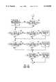
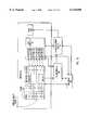
- the rendering pipelineis responsible for most of the calculation required to determine an image based on a scene.
- processor 168carries out the rendering process in two passes.
- the processor 168utilizes a culling module 164 and a polygon rendering module 166, both of which may be either independent of the processor, or implemented as functions carried out by the processor 168.
- a memory 170is configured to accommodate objects 116 in the form of compiled object models 114, data structures 162, and an image 164.
- Data structure 162includes a number of counters 160, each of which is associated with a class 1 or class 2 border edge in compiled object model 114.
- the processor 168begins by creating 900 a list of all edge indexes from all compiled object models 114 in the scene, and associating a counter 160 with each edge index.
- Each object model 114has a unique "base" address through which the edge indices are accessed, so edges with the same index on different object models 114 are seen as separate edges.
- the processor 168transforms 902 the coordinates of each vertex 110 of each primitive to account for any rotation, translation or stretching of the objects 116 in the scene.
- the processor 168then begins to loop through each of the objects 116, strips 104, fans 106, and triangles 108 in the scene.
- the first object 116 in the sceneis selected
- the first strip 104 or fan 106 in the selected object 116is selected
- the first triangle 108 in the selected strip 104 or fan 106is selected.
- a culling module 164determines 908 whether the selected triangle 108 should be back-face culled, or whether it needs to be rendered. If the selected triangle 108 is not back-face culled, then the counter associated with the starting edge is increased 909 by one.
- the processor 168determines 912 whether the selected triangle 108 is the last one in the strip 104 or fan 106. If not, the next triangle 108 is selected 916, and the method continues with the culling module 164 determining 910 whether the selected triangle 108 should be back-face culled. If so, the method continues with step 912. If the selected triangle 108 is determined 912 to be the last one, the culling module 164 determines 917 whether the selected triangle 108 should be back-face culled. If not, the counter associated with the ending edge is increased 918 by one.
- the processor 168determines 919 whether the selected strip 104 or fan 106 is the last one. If not, then the next strip 104 or fan 106 is selected 920, and the method starting with step 907 is repeated. If the selected strip 104 or fan 106 is the last, then the processor 168 determines 922 whether the selected object 116 is the last one in the scene. If not, the processor 168 selects 924 the next object 116, and the method starting with step 906 is repeated. If the selected object 116 is the last one, then the processor 168 moves on to the second pass.
- the polygon rendering module 166takes over, and the Z buffering scheme illustrated in FIG. 11b is used to determine which points are obscured by other objects 116.
- the polygon rendering module 168increases the counters 160 associated with the edge indexes for all class 1 and class 2 border edges of the triangle 108. When the rendering of objects 116 is finished, some edge indexes will have counters which are at zero. These edge indexes are associated with class 1 or class 2 border edges which have not been drawn, and therefore do not need to be anti-aliased. Other edge indexes will have counters which are set to more than one.
- edge indexesare associated with class 1 or class 2 border edges for which triangles 108 have been drawn on both sides, indicating that these edges are not silhouette edges of the object and do not need to be anti-aliased. Only those edge indexes with counters set to exactly one are associated with class 1 or class 2 silhouette edges, because in that case only one bordering triangle 108 has been drawn.
- the polygon rendering module 166loops through all of the pixels which represent points on the triangle 108.
- the first pixelis selected.
- the polygon rendering module 166determines 926 whether the point represented by the pixel is obscured, by referring to the Z buffer. If the point is obscured, the polygon rendering module 166 goes to step 928, described below. If the point is not obscured, the polygon rendering module 166 uses 932 information about the triangle 108, such as color, texture, and reflectance; and information about the scene, such as the position of lights, to determine the color of the triangle 108 at that point. The color is then applied to the appropriate pixel in the image, and the Z-buffer is updated with the Z value of the represented point.
- the polygon rendering module 166determines 928 whether the selected pixel is the last one in the triangle 108. If not, the next pixel is selected 930, and the method starting with step 926 is repeated. If the selected pixel is the last one for the triangle 928, the polygon rendering module 166 continues on to step 912, described above. This is the general process followed by the polygon rendering module 166 in constructing an image in the frame buffer.
- the processor 168begins the second pass, during which anti-aliasing of the silhouette edges takes place.
- FIG. 11c and 11dillustrate the second pass.
- the processor 168begins by selecting 934 the first object 116 of the scene, selecting 936 the first strip 104 or fan 106 of the selected object 116, and selecting 938 the first triangle 108 of the selected strip 104 for fan 106.
- the processor 168clears a flag which is used later in the process.
- the culling module 164determines whether the selected triangle 108 has been back-face culled.
- the processor 168keeps a list of triangles 108 which were back-face culled during the first pass, for use in the second pass. Doing this, however, requires the use of a significant amount of memory for the list.
- the culling module 164 used in the first passis reused in the second pass, in order to avoid using a large amount of additional memory. If the triangle 108 has been back-face culled, the processor 168 sets 941 the flag discussed above, for use when the next triangle 108 is examined. The processor 168 then determines 962 whether the selected triangle 108 is the last one in the strip 104 or fan 106. If not, the next triangle 108 is selected 964, and the method starting with step 940 is repeated.
- the processor 168determines 966 whether the selected strip 104 or fan 106 is the last one in the selected object 116. If not, then the next strip 104 or fan 106 is selected 968, and the method starting with step 938 is repeated. If the selected strip 104 or fan 106 is the last, then the processor 168 determines 970 whether the selected object 116 is the last one in the scene. If not, the processor 168 selects 972 the next object 116, and the method starting with step 936 is repeated. If the selected object 116 is the last one, then the second pass comes to an end.
- step 944the processor 168 uses 942 the flag to determine whether the previous triangle 108 had been back-face culled. If it had been, then the class 3 border edge adjoining the two triangles 108 is anti-aliased 944 by a process described below. Whether or not step 944 is executed following step 942, the processor 168 next determines 946 whether the selected triangle 108 is the last one in the strip 104 or fan 106. If so, the processor 168 determines 948 whether the counter associated with the ending edge is set to one. If it is, then this ending edge is anti-aliased 950 by the process described below.
- the processor 168next determines 952 whether the selected triangle 108 is the first one in the strip 104 or fan 106. If so, the processor 168 determines 954 whether the counter associated with the starting edge is set to one. If it is, then this starting edge is anti-aliased 956 by the process described below. Following step 956, or following a negative determination at steps 952 or 954, the processor 168 determines 958 whether the counter for the class 1 border edge of the triangle 108 is set to one. If it is, the class 1 border edge is anti-aliased 960 by the process described below. Whether or not step 960 is executed, the processor 168 next clears the flag 961. Then the process beginning with step 962 is repeated.
- the first step in anti-aliasing an edge 148is to determine 974 the slope of the edge 148. If the absolute value of the slope is less than or equal to one, the edge 148 is classified as horizontal. Otherwise the edge 148 is classified as vertical.
- two triangles 150are determined 976. If the edge 148 has been classified horizontal, the two triangles 150 form a parallelogram adjoining the edge 148 and a line 155 one pixel in the vertical direction away from, and parallel to, the edge 148. This is illustrated in FIG. 14. If the edge 148 has been classified as vertical, the two triangles 150 form a parallelogram adjoining the edge 148 and a line 155 one pixel in the horizontal direction away from, and parallel to, the edge 148.
- Line 155is on the opposite side of the edge 148 from the triangle 108 which was drawn.
- the parallelogram formed by the two triangles 150is coplanar with the drawn triangle 108 adjoining the edge 148.
- One of the triangles 150shares two vertices 110 with drawn triangle 108, and the other shares one vertex 110 with drawn triangle 108. All channel information, including opacity, present in the shared vertices 110 is used for the same vertices 110 in the new triangles 150.
- the vertices 110 of the triangles 150 which are not shared with triangle 108are set to an opacity level corresponding to transparent, but otherwise each uses the same channel information as the nearest vertex 110.
- the parallelogram 155 formed by these triangles 150shares the opacity of triangle 108 on the shared edge, and is transparent on the opposite side.
- the first of the new triangles 150is selected 978, and the first pixel of this triangle 150 is selected 980.
- the Z bufferis then used to determine 982 whether this pixel is obscured by another object. If it has not been obscured, the new color for that pixel is calculated 984.
- the new coloris a combination of the current pixel color value and the color of triangle 150, as determined from the associated channel information.
- the opacity of the pixelis interpolated based on the location of the pixel in triangle 150. An opacity value corresponding to transparent would result in the current pixel color value being preserved, and an opacity value corresponding to completely opaque would result in the pixel receiving the triangle 150 color. Opacity values between these extremes result in a new color which is a combination of the other two colors.
- a testis made to determine 986 whether this is the last pixel in triangle 150. If it is not, the next pixel is selected 988 and the process starting with step 982 is repeated. If the current pixel is the last, then it is determined 990 whether the current triangle 108 is the second of the two. If it is not, then the second triangle 108 is selected 992, and the process starting with step 980 is repeated. If the current triangle 108 is the second, then the anti-aliasing process is finished.
Landscapes
- Engineering & Computer Science (AREA)
- Computer Graphics (AREA)
- Physics & Mathematics (AREA)
- General Physics & Mathematics (AREA)
- Theoretical Computer Science (AREA)
- Image Generation (AREA)
Abstract
Description
TABLE 1 ______________________________________ Triangle is counter- Vertex forClass 1 edge. Triangle is clockwise. clockwise. ______________________________________ Triangle is part of a strip. First Third Triangle is part of a fan. Third Second ______________________________________
TABLE 2 ______________________________________ Vertex associated with the Triangle is counter- starting edge (class 2). Triangle is clockwise. clockwise. ______________________________________ Triangle is part of a strip. Second First Triangle is part of a fan. Second First ______________________________________
TABLE 3 ______________________________________ Vertex associated with the Triangle is counter- ending edge (class 2). Triangle is clockwise. clockwise. ______________________________________ Triangle is part of a strip. Third Second Triangle is part of a fan. First Third ______________________________________
Claims (15)
Priority Applications (4)
| Application Number | Priority Date | Filing Date | Title |
|---|---|---|---|
| US09/057,327US6115050A (en) | 1998-04-08 | 1998-04-08 | Object-based anti-aliasing |
| AU35498/99AAU3549899A (en) | 1998-04-08 | 1999-04-06 | Object-based anti-aliasing |
| PCT/US1999/007571WO1999052079A1 (en) | 1998-04-08 | 1999-04-06 | Object-based anti-aliasing |
| US09/584,463US6529207B1 (en) | 1998-04-08 | 2000-05-31 | Identifying silhouette edges of objects to apply anti-aliasing |
Applications Claiming Priority (1)
| Application Number | Priority Date | Filing Date | Title |
|---|---|---|---|
| US09/057,327US6115050A (en) | 1998-04-08 | 1998-04-08 | Object-based anti-aliasing |
Related Child Applications (1)
| Application Number | Title | Priority Date | Filing Date |
|---|---|---|---|
| US09/584,463DivisionUS6529207B1 (en) | 1998-04-08 | 2000-05-31 | Identifying silhouette edges of objects to apply anti-aliasing |
Publications (1)
| Publication Number | Publication Date |
|---|---|
| US6115050Atrue US6115050A (en) | 2000-09-05 |
Family
ID=22009913
Family Applications (2)
| Application Number | Title | Priority Date | Filing Date |
|---|---|---|---|
| US09/057,327Expired - LifetimeUS6115050A (en) | 1998-04-08 | 1998-04-08 | Object-based anti-aliasing |
| US09/584,463Expired - LifetimeUS6529207B1 (en) | 1998-04-08 | 2000-05-31 | Identifying silhouette edges of objects to apply anti-aliasing |
Family Applications After (1)
| Application Number | Title | Priority Date | Filing Date |
|---|---|---|---|
| US09/584,463Expired - LifetimeUS6529207B1 (en) | 1998-04-08 | 2000-05-31 | Identifying silhouette edges of objects to apply anti-aliasing |
Country Status (3)
| Country | Link |
|---|---|
| US (2) | US6115050A (en) |
| AU (1) | AU3549899A (en) |
| WO (1) | WO1999052079A1 (en) |
Cited By (32)
| Publication number | Priority date | Publication date | Assignee | Title |
|---|---|---|---|---|
| US6320596B1 (en)* | 1999-02-24 | 2001-11-20 | Intel Corporation | Processing polygon strips |
| US20020075276A1 (en)* | 1999-10-25 | 2002-06-20 | Intel Corporation, Delaware Corporation | Rendering a silhouette edge |
| US6421060B1 (en)* | 1999-03-31 | 2002-07-16 | International Business Machines Corporation | Memory efficient system and method for creating anti-aliased images |
| US20020186215A1 (en)* | 2001-06-07 | 2002-12-12 | Cronin Thomas M. | Rendering a three-dimensional model using a dither pattern |
| US6535219B1 (en)* | 2000-03-30 | 2003-03-18 | Intel Corporation | Method and apparatus to display objects in a computer system |
| US20030058240A1 (en)* | 2001-09-25 | 2003-03-27 | Lake Adam T. | Reducing the resolution of bones in a three-dimensional model |
| US20030071822A1 (en)* | 2001-10-17 | 2003-04-17 | Lake Adam T. | Generating a shadow for a three-dimensional model |
| US20030128203A1 (en)* | 2002-01-04 | 2003-07-10 | Marshall Carl S. | Determining a node path through a node graph |
| US6608627B1 (en)* | 1999-10-04 | 2003-08-19 | Intel Corporation | Rendering a two-dimensional image |
| US20030234792A1 (en)* | 2002-06-25 | 2003-12-25 | Stephen Junkins | Polygon binning process for tile-based rendering |
| GB2390949A (en)* | 2002-07-17 | 2004-01-21 | Sony Uk Ltd | Anti-aliasing of a foreground image to be combined with a background image |
| US20040017368A1 (en)* | 2002-07-26 | 2004-01-29 | Martin Isenburg | Mesh compression process |
| US20040125091A1 (en)* | 2002-12-27 | 2004-07-01 | Microsoft Corporation | Method and system for tessellating a polygon |
| US20040174379A1 (en)* | 2003-03-03 | 2004-09-09 | Collodi David J. | Method and system for real-time anti-aliasing |
| US20050083329A1 (en)* | 1999-10-29 | 2005-04-21 | Intel Corporation, A California Corporation | Image processing |
| US6919906B2 (en)* | 2001-05-08 | 2005-07-19 | Microsoft Corporation | Discontinuity edge overdraw |
| US7061501B1 (en) | 2000-11-07 | 2006-06-13 | Intel Corporation | Rendering a pencil-sketch image |
| US7116330B2 (en) | 2001-02-28 | 2006-10-03 | Intel Corporation | Approximating motion using a three-dimensional model |
| US20060250414A1 (en)* | 2005-05-03 | 2006-11-09 | Vladimir Golovin | System and method of anti-aliasing computer images |
| US7146297B2 (en) | 2002-03-27 | 2006-12-05 | Intel Corporation | Detecting collisions of three-dimensional models |
| US7180523B1 (en) | 2000-03-31 | 2007-02-20 | Intel Corporation | Trimming surfaces |
| US7190374B2 (en) | 2001-02-28 | 2007-03-13 | Intel Corporation | Shading polygons from a three-dimensional model |
| US7301547B2 (en) | 2002-03-22 | 2007-11-27 | Intel Corporation | Augmented reality system |
| US7768512B1 (en)* | 1998-08-10 | 2010-08-03 | Via Technologies, Inc. | System and method for rasterizing primitives using direct interpolation |
| US20110057931A1 (en)* | 2009-09-09 | 2011-03-10 | Vineet Goel | Tessellation Engine and Applications Thereof |
| US7953260B2 (en) | 2006-06-09 | 2011-05-31 | Craniosim Solutions, Inc. | Predicting movement of soft tissue of the face in response to movement of underlying bone |
| US20120256915A1 (en)* | 2010-06-30 | 2012-10-11 | Jenkins Barry L | System and method of procedural visibility for interactive and broadcast streaming of entertainment, advertising, and tactical 3d graphical information using a visibility event codec |
| US20140306955A1 (en)* | 2013-04-16 | 2014-10-16 | Autodesk, Inc. | Voxelization techniques |
| US9300842B1 (en) | 2014-12-16 | 2016-03-29 | Xerox Corporation | Gated edge enhancement using orthogonal rational counters |
| US10628907B2 (en)* | 2017-04-01 | 2020-04-21 | Intel Corporation | Multi-resolution smoothing |
| US11127106B2 (en) | 2019-06-28 | 2021-09-21 | Intel Corporation | Runtime flip stability characterization |
| US11409341B2 (en) | 2019-10-01 | 2022-08-09 | Intel Corporation | Repeating graphics render pattern detection |
Families Citing this family (43)
| Publication number | Priority date | Publication date | Assignee | Title |
|---|---|---|---|---|
| US6421051B1 (en) | 1998-06-18 | 2002-07-16 | Spatial Corporation | Multi-resolution geometry |
| AU765466B2 (en)* | 1999-12-22 | 2003-09-18 | Canon Kabushiki Kaisha | Anti-aliased polygon rendering |
| JP2002140722A (en)* | 2000-08-23 | 2002-05-17 | Sony Computer Entertainment Inc | Apparatus and method for drawing an image from which aliasing has been removed |
| US7286138B2 (en)* | 2001-05-08 | 2007-10-23 | Microsoft Corporation | Discontinuity edge overdraw |
| US7619624B2 (en) | 2001-06-25 | 2009-11-17 | Micron Technology, Inc. | Methods and apparatus for rendering or preparing digital objects or portions thereof for subsequent processing |
| US6937236B2 (en)* | 2001-06-25 | 2005-08-30 | Micron Technology, Inc. | Methods and apparatus for culling sorted, back facing graphics data |
| US7050067B2 (en)* | 2003-01-13 | 2006-05-23 | Microsoft Corporation | Hardware accelerated anti-aliased primitives using alpha gradients |
| US8732644B1 (en) | 2003-09-15 | 2014-05-20 | Nvidia Corporation | Micro electro mechanical switch system and method for testing and configuring semiconductor functional circuits |
| US8775997B2 (en)* | 2003-09-15 | 2014-07-08 | Nvidia Corporation | System and method for testing and configuring semiconductor functional circuits |
| US8872833B2 (en) | 2003-09-15 | 2014-10-28 | Nvidia Corporation | Integrated circuit configuration system and method |
| US8711161B1 (en) | 2003-12-18 | 2014-04-29 | Nvidia Corporation | Functional component compensation reconfiguration system and method |
| US8723231B1 (en) | 2004-09-15 | 2014-05-13 | Nvidia Corporation | Semiconductor die micro electro-mechanical switch management system and method |
| US7173631B2 (en)* | 2004-09-23 | 2007-02-06 | Qualcomm Incorporated | Flexible antialiasing in embedded devices |
| US8711156B1 (en) | 2004-09-30 | 2014-04-29 | Nvidia Corporation | Method and system for remapping processing elements in a pipeline of a graphics processing unit |
| US20060082593A1 (en)* | 2004-10-19 | 2006-04-20 | Microsoft Corporation | Method for hardware accelerated anti-aliasing in 3D |
| US8427496B1 (en) | 2005-05-13 | 2013-04-23 | Nvidia Corporation | Method and system for implementing compression across a graphics bus interconnect |
| US8698811B1 (en) | 2005-12-15 | 2014-04-15 | Nvidia Corporation | Nested boustrophedonic patterns for rasterization |
| US9117309B1 (en) | 2005-12-19 | 2015-08-25 | Nvidia Corporation | Method and system for rendering polygons with a bounding box in a graphics processor unit |
| US7791617B2 (en)* | 2005-12-19 | 2010-09-07 | Nvidia Corporation | Method and system for rendering polygons having abutting edges |
| US8390645B1 (en)* | 2005-12-19 | 2013-03-05 | Nvidia Corporation | Method and system for rendering connecting antialiased line segments |
| US8928676B2 (en)* | 2006-06-23 | 2015-01-06 | Nvidia Corporation | Method for parallel fine rasterization in a raster stage of a graphics pipeline |
| US8477134B1 (en) | 2006-06-30 | 2013-07-02 | Nvidia Corporation | Conservative triage of polygon status using low precision edge evaluation and high precision edge evaluation |
| US20080062204A1 (en)* | 2006-09-08 | 2008-03-13 | Microsoft Corporation | Automated pixel snapping for anti-aliased rendering |
| US8427487B1 (en) | 2006-11-02 | 2013-04-23 | Nvidia Corporation | Multiple tile output using interface compression in a raster stage |
| US8482567B1 (en) | 2006-11-03 | 2013-07-09 | Nvidia Corporation | Line rasterization techniques |
| US8724483B2 (en) | 2007-10-22 | 2014-05-13 | Nvidia Corporation | Loopback configuration for bi-directional interfaces |
| US8063903B2 (en)* | 2007-11-09 | 2011-11-22 | Nvidia Corporation | Edge evaluation techniques for graphics hardware |
| US8780123B2 (en) | 2007-12-17 | 2014-07-15 | Nvidia Corporation | Interrupt handling techniques in the rasterizer of a GPU |
| US9064333B2 (en) | 2007-12-17 | 2015-06-23 | Nvidia Corporation | Interrupt handling techniques in the rasterizer of a GPU |
| KR101574279B1 (en)* | 2008-04-04 | 2015-12-04 | 어드밴스드 마이크로 디바이시즈, 인코포레이티드 | Filtering method and apparatus for anti-aliasing |
| US8681861B2 (en) | 2008-05-01 | 2014-03-25 | Nvidia Corporation | Multistandard hardware video encoder |
| US8923385B2 (en) | 2008-05-01 | 2014-12-30 | Nvidia Corporation | Rewind-enabled hardware encoder |
| US20110063309A1 (en)* | 2009-09-16 | 2011-03-17 | Nvidia Corporation | User interface for co-processing techniques on heterogeneous graphics processing units |
| US9530189B2 (en) | 2009-12-31 | 2016-12-27 | Nvidia Corporation | Alternate reduction ratios and threshold mechanisms for framebuffer compression |
| US9331869B2 (en) | 2010-03-04 | 2016-05-03 | Nvidia Corporation | Input/output request packet handling techniques by a device specific kernel mode driver |
| US20110216068A1 (en)* | 2010-03-08 | 2011-09-08 | Sathe Rahul P | Edge processing techniques |
| US9171350B2 (en) | 2010-10-28 | 2015-10-27 | Nvidia Corporation | Adaptive resolution DGPU rendering to provide constant framerate with free IGPU scale up |
| US9153193B2 (en)* | 2011-09-09 | 2015-10-06 | Microsoft Technology Licensing, Llc | Primitive rendering using a single primitive type |
| US9591309B2 (en) | 2012-12-31 | 2017-03-07 | Nvidia Corporation | Progressive lossy memory compression |
| US9607407B2 (en) | 2012-12-31 | 2017-03-28 | Nvidia Corporation | Variable-width differential memory compression |
| US9710894B2 (en) | 2013-06-04 | 2017-07-18 | Nvidia Corporation | System and method for enhanced multi-sample anti-aliasing |
| US9832388B2 (en) | 2014-08-04 | 2017-11-28 | Nvidia Corporation | Deinterleaving interleaved high dynamic range image by using YUV interpolation |
| CN112150593A (en)* | 2020-08-05 | 2020-12-29 | 成都偶邦智能科技有限公司 | Method for realizing real-time behavior rendering of client 3D digital virtual human based on edge calculation |
Citations (4)
| Publication number | Priority date | Publication date | Assignee | Title |
|---|---|---|---|---|
| US5287436A (en)* | 1990-04-26 | 1994-02-15 | Honeywell Inc. | Polygon sort engine |
| US5303339A (en)* | 1989-10-31 | 1994-04-12 | Kabushiki Kaisha Toshiba | Three-dimensional graphic processing apparatus |
| US5574835A (en)* | 1993-04-06 | 1996-11-12 | Silicon Engines, Inc. | Bounding box and projections detection of hidden polygons in three-dimensional spatial databases |
| US5742277A (en)* | 1995-10-06 | 1998-04-21 | Silicon Graphics, Inc. | Antialiasing of silhouette edges |
Family Cites Families (6)
| Publication number | Priority date | Publication date | Assignee | Title |
|---|---|---|---|---|
| US3889107A (en)* | 1972-10-16 | 1975-06-10 | Evans & Sutherland Computer Co | System of polygon sorting by dissection |
| US5359704A (en)* | 1991-10-30 | 1994-10-25 | International Business Machines Corporation | Method for selecting silhouette and visible edges in wire frame images in a computer graphics display system |
| US5357600A (en)* | 1992-10-15 | 1994-10-18 | Sun Microsystems, Inc. | Method and apparatus for the rendering of curved surfaces using a cone of normals |
| US5729672A (en)* | 1993-07-30 | 1998-03-17 | Videologic Limited | Ray tracing method and apparatus for projecting rays through an object represented by a set of infinite surfaces |
| EP0723689B1 (en)* | 1993-10-15 | 1998-02-04 | EVANS & SUTHERLAND COMPUTER CORPORATION | Direct rendering of textured height fields |
| US6111582A (en)* | 1996-12-20 | 2000-08-29 | Jenkins; Barry L. | System and method of image generation and encoding using primitive reprojection |
- 1998
- 1998-04-08USUS09/057,327patent/US6115050A/ennot_activeExpired - Lifetime
- 1999
- 1999-04-06AUAU35498/99Apatent/AU3549899A/ennot_activeAbandoned
- 1999-04-06WOPCT/US1999/007571patent/WO1999052079A1/enactiveApplication Filing
- 2000
- 2000-05-31USUS09/584,463patent/US6529207B1/ennot_activeExpired - Lifetime
Patent Citations (4)
| Publication number | Priority date | Publication date | Assignee | Title |
|---|---|---|---|---|
| US5303339A (en)* | 1989-10-31 | 1994-04-12 | Kabushiki Kaisha Toshiba | Three-dimensional graphic processing apparatus |
| US5287436A (en)* | 1990-04-26 | 1994-02-15 | Honeywell Inc. | Polygon sort engine |
| US5574835A (en)* | 1993-04-06 | 1996-11-12 | Silicon Engines, Inc. | Bounding box and projections detection of hidden polygons in three-dimensional spatial databases |
| US5742277A (en)* | 1995-10-06 | 1998-04-21 | Silicon Graphics, Inc. | Antialiasing of silhouette edges |
Cited By (54)
| Publication number | Priority date | Publication date | Assignee | Title |
|---|---|---|---|---|
| US7768512B1 (en)* | 1998-08-10 | 2010-08-03 | Via Technologies, Inc. | System and method for rasterizing primitives using direct interpolation |
| US6320596B1 (en)* | 1999-02-24 | 2001-11-20 | Intel Corporation | Processing polygon strips |
| US6421060B1 (en)* | 1999-03-31 | 2002-07-16 | International Business Machines Corporation | Memory efficient system and method for creating anti-aliased images |
| US6608627B1 (en)* | 1999-10-04 | 2003-08-19 | Intel Corporation | Rendering a two-dimensional image |
| US20020075276A1 (en)* | 1999-10-25 | 2002-06-20 | Intel Corporation, Delaware Corporation | Rendering a silhouette edge |
| US7113191B2 (en) | 1999-10-25 | 2006-09-26 | Intel Corporation | Rendering a silhouette edge |
| US6822658B1 (en)* | 1999-10-25 | 2004-11-23 | Intel Corporation | Rendering a silhouette edge |
| US20050083329A1 (en)* | 1999-10-29 | 2005-04-21 | Intel Corporation, A California Corporation | Image processing |
| US7209138B2 (en) | 1999-10-29 | 2007-04-24 | Intel Corporation | Image processing |
| US6535219B1 (en)* | 2000-03-30 | 2003-03-18 | Intel Corporation | Method and apparatus to display objects in a computer system |
| US7180523B1 (en) | 2000-03-31 | 2007-02-20 | Intel Corporation | Trimming surfaces |
| US7061501B1 (en) | 2000-11-07 | 2006-06-13 | Intel Corporation | Rendering a pencil-sketch image |
| US7116330B2 (en) | 2001-02-28 | 2006-10-03 | Intel Corporation | Approximating motion using a three-dimensional model |
| US7190374B2 (en) | 2001-02-28 | 2007-03-13 | Intel Corporation | Shading polygons from a three-dimensional model |
| US6919906B2 (en)* | 2001-05-08 | 2005-07-19 | Microsoft Corporation | Discontinuity edge overdraw |
| US6980206B2 (en) | 2001-06-07 | 2005-12-27 | Intel Corporation | Rendering a three-dimensional model using a dither pattern |
| US20020186215A1 (en)* | 2001-06-07 | 2002-12-12 | Cronin Thomas M. | Rendering a three-dimensional model using a dither pattern |
| US20030058240A1 (en)* | 2001-09-25 | 2003-03-27 | Lake Adam T. | Reducing the resolution of bones in a three-dimensional model |
| US6924804B2 (en) | 2001-09-25 | 2005-08-02 | Intel Corporation | Reducing the resolution of bones in a three-dimensional model |
| US20030071822A1 (en)* | 2001-10-17 | 2003-04-17 | Lake Adam T. | Generating a shadow for a three-dimensional model |
| US6906724B2 (en) | 2001-10-17 | 2005-06-14 | Lntel Corporation | Generating a shadow for a three-dimensional model |
| US9542774B2 (en) | 2002-01-04 | 2017-01-10 | Intel Corporation | Determining a node paththrough a node graph |
| US8135566B2 (en) | 2002-01-04 | 2012-03-13 | Intel Corporation | Determining a node path through a node graph |
| US20090237398A1 (en)* | 2002-01-04 | 2009-09-24 | Intel Corporation | Determining a node path through a node graph |
| US20030128203A1 (en)* | 2002-01-04 | 2003-07-10 | Marshall Carl S. | Determining a node path through a node graph |
| US7548241B2 (en) | 2002-01-04 | 2009-06-16 | Intel Corporation | Determining a node path through a node graph |
| US7301547B2 (en) | 2002-03-22 | 2007-11-27 | Intel Corporation | Augmented reality system |
| US7146297B2 (en) | 2002-03-27 | 2006-12-05 | Intel Corporation | Detecting collisions of three-dimensional models |
| US6975318B2 (en) | 2002-06-25 | 2005-12-13 | Intel Corporation | Polygon binning process for tile-based rendering |
| US20030234792A1 (en)* | 2002-06-25 | 2003-12-25 | Stephen Junkins | Polygon binning process for tile-based rendering |
| US20040109005A1 (en)* | 2002-07-17 | 2004-06-10 | Witt Sarah Elizabeth | Video processing |
| GB2390949A (en)* | 2002-07-17 | 2004-01-21 | Sony Uk Ltd | Anti-aliasing of a foreground image to be combined with a background image |
| US6982715B2 (en) | 2002-07-26 | 2006-01-03 | Intel Corporation | Mesh compression process |
| US20040017368A1 (en)* | 2002-07-26 | 2004-01-29 | Martin Isenburg | Mesh compression process |
| US20040125091A1 (en)* | 2002-12-27 | 2004-07-01 | Microsoft Corporation | Method and system for tessellating a polygon |
| US7002574B2 (en) | 2002-12-27 | 2006-02-21 | Microsoft Corporation | Method and system for tessellating a polygon |
| US20040174379A1 (en)* | 2003-03-03 | 2004-09-09 | Collodi David J. | Method and system for real-time anti-aliasing |
| US20060250414A1 (en)* | 2005-05-03 | 2006-11-09 | Vladimir Golovin | System and method of anti-aliasing computer images |
| US7953260B2 (en) | 2006-06-09 | 2011-05-31 | Craniosim Solutions, Inc. | Predicting movement of soft tissue of the face in response to movement of underlying bone |
| CN102598063A (en)* | 2009-09-09 | 2012-07-18 | 先进微装置公司 | Tessellation engine and applications thereof |
| CN102598063B (en)* | 2009-09-09 | 2016-06-08 | 先进微装置公司 | Surface subdivision engine and its application |
| US20110057931A1 (en)* | 2009-09-09 | 2011-03-10 | Vineet Goel | Tessellation Engine and Applications Thereof |
| US8884957B2 (en)* | 2009-09-09 | 2014-11-11 | Advanced Micro Devices, Inc. | Tessellation engine and applications thereof |
| US20120256915A1 (en)* | 2010-06-30 | 2012-10-11 | Jenkins Barry L | System and method of procedural visibility for interactive and broadcast streaming of entertainment, advertising, and tactical 3d graphical information using a visibility event codec |
| US9171396B2 (en)* | 2010-06-30 | 2015-10-27 | Primal Space Systems Inc. | System and method of procedural visibility for interactive and broadcast streaming of entertainment, advertising, and tactical 3D graphical information using a visibility event codec |
| US20150279091A9 (en)* | 2013-04-16 | 2015-10-01 | Autodesk, Inc. | Voxelization techniques |
| US20140306955A1 (en)* | 2013-04-16 | 2014-10-16 | Autodesk, Inc. | Voxelization techniques |
| US10535187B2 (en)* | 2013-04-16 | 2020-01-14 | Autodesk, Inc. | Voxelization techniques |
| US9300842B1 (en) | 2014-12-16 | 2016-03-29 | Xerox Corporation | Gated edge enhancement using orthogonal rational counters |
| US10628907B2 (en)* | 2017-04-01 | 2020-04-21 | Intel Corporation | Multi-resolution smoothing |
| US11030712B2 (en) | 2017-04-01 | 2021-06-08 | Intel Corporation | Multi-resolution smoothing |
| US11127106B2 (en) | 2019-06-28 | 2021-09-21 | Intel Corporation | Runtime flip stability characterization |
| US11409341B2 (en) | 2019-10-01 | 2022-08-09 | Intel Corporation | Repeating graphics render pattern detection |
| US11914438B2 (en) | 2019-10-01 | 2024-02-27 | Intel Corporation | Repeating graphics render pattern detection |
Also Published As
| Publication number | Publication date |
|---|---|
| WO1999052079A1 (en) | 1999-10-14 |
| AU3549899A (en) | 1999-10-25 |
| US6529207B1 (en) | 2003-03-04 |
Similar Documents
| Publication | Publication Date | Title |
|---|---|---|
| US6115050A (en) | Object-based anti-aliasing | |
| US6411294B1 (en) | Image display apparatus and image display method | |
| US6038031A (en) | 3D graphics object copying with reduced edge artifacts | |
| Diepstraten et al. | Transparency in interactive technical illustrations | |
| US6285378B1 (en) | Method and apparatus for span and subspan sorting rendering system | |
| US6005580A (en) | Method and apparatus for performing post-process antialiasing of polygon edges | |
| US6961065B2 (en) | Image processor, components thereof, and rendering method | |
| US6954202B2 (en) | Image-based methods of representation and rendering of three-dimensional object and animated three-dimensional object | |
| US7116337B2 (en) | Transparent depth sorting | |
| US5877773A (en) | Multi-pass clipping in a geometry accelerator | |
| US20050068333A1 (en) | Image processing apparatus and method of same | |
| US20050134588A1 (en) | Method and apparatus for image processing | |
| US6424345B1 (en) | Binsorter triangle insertion optimization | |
| US6292192B1 (en) | System and method for the direct rendering of curve bounded objects | |
| US6670955B1 (en) | Method and system for sort independent alpha blending of graphic fragments | |
| WO1997005576A9 (en) | Method and apparatus for span and subspan sorting rendering system | |
| WO2000013147A1 (en) | System and method for combining multiple video streams | |
| GB2259432A (en) | Three dimensional graphics processing | |
| US6184893B1 (en) | Method and system for filtering texture map data for improved image quality in a graphics computer system | |
| US20050068326A1 (en) | Image processing apparatus and method of same | |
| JP3037865B2 (en) | 3D sprite drawing device | |
| US6690369B1 (en) | Hardware-accelerated photoreal rendering | |
| JP4311877B2 (en) | Anti-aliasing of subsampled texture edges | |
| JPH07182526A (en) | Display method of graphics display device | |
| JPH09319892A (en) | Image processing apparatus and processing method thereof |
Legal Events
| Date | Code | Title | Description |
|---|---|---|---|
| AS | Assignment | Owner name:CAGENT TECHNOLOGIES, INC., CALIFORNIA Free format text:ASSIGNMENT OF ASSIGNORS INTEREST;ASSIGNORS:LANDAU, EDOUARD;SFARTI, ADRIAN;MALAMY, ADAM;AND OTHERS;REEL/FRAME:009083/0904;SIGNING DATES FROM 19980327 TO 19980406 | |
| AS | Assignment | Owner name:VIRGINIA COMMONWEALTH UNIVERSITY, VIRGINIA Free format text:ASSIGNMENT OF ASSIGNORS INTEREST;ASSIGNORS:GLENNON, RICHARD A.;YOUNG, RICHARD;REEL/FRAME:009167/0517 Effective date:19980507 | |
| STCF | Information on status: patent grant | Free format text:PATENTED CASE | |
| CC | Certificate of correction | ||
| AS | Assignment | Owner name:WEB NETWORKS, INC., CALIFORNIA Free format text:ASSIGNMENT OF ASSIGNORS INTEREST;ASSIGNOR:CAGENT TECHNOLOGIES, INC.;REEL/FRAME:013860/0122 Effective date:19980629 | |
| FPAY | Fee payment | Year of fee payment:4 | |
| FPAY | Fee payment | Year of fee payment:8 | |
| FPAY | Fee payment | Year of fee payment:12 | |
| AS | Assignment | Owner name:MICROSOFT CORPORATION, WASHINGTON Free format text:MERGER;ASSIGNOR:WEBTV NETWORKS, INC.;REEL/FRAME:032956/0577 Effective date:20020628 | |
| AS | Assignment | Owner name:MICROSOFT TECHNOLOGY LICENSING, LLC, WASHINGTON Free format text:ASSIGNMENT OF ASSIGNORS INTEREST;ASSIGNOR:MICROSOFT CORPORATION;REEL/FRAME:034541/0001 Effective date:20141014 |