US6114770A - Low profile semiconductor package - Google Patents
Low profile semiconductor packageDownload PDFInfo
- Publication number
- US6114770A US6114770AUS09/121,272US12127298AUS6114770AUS 6114770 AUS6114770 AUS 6114770AUS 12127298 AUS12127298 AUS 12127298AUS 6114770 AUS6114770 AUS 6114770A
- Authority
- US
- United States
- Prior art keywords
- conductors
- bond pads
- die
- matrix
- wafer section
- Prior art date
- Legal status (The legal status is an assumption and is not a legal conclusion. Google has not performed a legal analysis and makes no representation as to the accuracy of the status listed.)
- Expired - Lifetime
Links
- 239000004065semiconductorSubstances0.000titleclaimsabstractdescription35
- 239000004020conductorSubstances0.000claimsabstractdescription54
- 239000011159matrix materialSubstances0.000claimsabstractdescription32
- 239000003566sealing materialSubstances0.000claimsabstractdescription14
- 239000000463materialSubstances0.000claimsdescription12
- 229910000679solderInorganic materials0.000claimsdescription12
- 230000008878couplingEffects0.000claimsdescription5
- 238000010168coupling processMethods0.000claimsdescription5
- 238000005859coupling reactionMethods0.000claimsdescription5
- 238000002161passivationMethods0.000claims2
- 239000000758substrateSubstances0.000description9
- 238000013461designMethods0.000description8
- 238000000034methodMethods0.000description6
- 238000005538encapsulationMethods0.000description4
- 230000003247decreasing effectEffects0.000description3
- 239000004033plasticSubstances0.000description3
- 229920003023plasticPolymers0.000description3
- 238000012360testing methodMethods0.000description3
- 239000004642PolyimideSubstances0.000description2
- 230000015572biosynthetic processEffects0.000description2
- 238000012986modificationMethods0.000description2
- 230000004048modificationEffects0.000description2
- 229920001721polyimidePolymers0.000description2
- 239000011347resinSubstances0.000description2
- 229920005989resinPolymers0.000description2
- XUIMIQQOPSSXEZ-UHFFFAOYSA-NSiliconChemical compound[Si]XUIMIQQOPSSXEZ-UHFFFAOYSA-N0.000description1
- 239000000919ceramicSubstances0.000description1
- 238000004891communicationMethods0.000description1
- 230000006835compressionEffects0.000description1
- 238000007906compressionMethods0.000description1
- 230000000694effectsEffects0.000description1
- 230000007613environmental effectEffects0.000description1
- 230000006870functionEffects0.000description1
- 230000017525heat dissipationEffects0.000description1
- 238000002347injectionMethods0.000description1
- 239000007924injectionSubstances0.000description1
- 238000009413insulationMethods0.000description1
- 239000012774insulation materialSubstances0.000description1
- 238000004519manufacturing processMethods0.000description1
- 238000001465metallisationMethods0.000description1
- 230000009972noncorrosive effectEffects0.000description1
- 238000004806packaging method and processMethods0.000description1
- 238000007747platingMethods0.000description1
- 239000003923scrap metalSubstances0.000description1
- 229910052710siliconInorganic materials0.000description1
- 239000010703siliconSubstances0.000description1
- 238000005476solderingMethods0.000description1
- 229920001187thermosetting polymerPolymers0.000description1
- 238000012546transferMethods0.000description1
Images

Classifications
- H—ELECTRICITY
- H01—ELECTRIC ELEMENTS
- H01L—SEMICONDUCTOR DEVICES NOT COVERED BY CLASS H10
- H01L23/00—Details of semiconductor or other solid state devices
- H01L23/48—Arrangements for conducting electric current to or from the solid state body in operation, e.g. leads, terminal arrangements ; Selection of materials therefor
- H01L23/488—Arrangements for conducting electric current to or from the solid state body in operation, e.g. leads, terminal arrangements ; Selection of materials therefor consisting of soldered or bonded constructions
- H01L23/498—Leads, i.e. metallisations or lead-frames on insulating substrates, e.g. chip carriers
- H01L23/49827—Via connections through the substrates, e.g. pins going through the substrate, coaxial cables
- H—ELECTRICITY
- H01—ELECTRIC ELEMENTS
- H01L—SEMICONDUCTOR DEVICES NOT COVERED BY CLASS H10
- H01L2224/00—Indexing scheme for arrangements for connecting or disconnecting semiconductor or solid-state bodies and methods related thereto as covered by H01L24/00
- H01L2224/01—Means for bonding being attached to, or being formed on, the surface to be connected, e.g. chip-to-package, die-attach, "first-level" interconnects; Manufacturing methods related thereto
- H01L2224/02—Bonding areas; Manufacturing methods related thereto
- H01L2224/04—Structure, shape, material or disposition of the bonding areas prior to the connecting process
- H01L2224/05—Structure, shape, material or disposition of the bonding areas prior to the connecting process of an individual bonding area
- H01L2224/0554—External layer
- H01L2224/0555—Shape
- H01L2224/05552—Shape in top view
- H01L2224/05554—Shape in top view being square
- H—ELECTRICITY
- H01—ELECTRIC ELEMENTS
- H01L—SEMICONDUCTOR DEVICES NOT COVERED BY CLASS H10
- H01L2224/00—Indexing scheme for arrangements for connecting or disconnecting semiconductor or solid-state bodies and methods related thereto as covered by H01L24/00
- H01L2224/01—Means for bonding being attached to, or being formed on, the surface to be connected, e.g. chip-to-package, die-attach, "first-level" interconnects; Manufacturing methods related thereto
- H01L2224/02—Bonding areas; Manufacturing methods related thereto
- H01L2224/04—Structure, shape, material or disposition of the bonding areas prior to the connecting process
- H01L2224/05—Structure, shape, material or disposition of the bonding areas prior to the connecting process of an individual bonding area
- H01L2224/0554—External layer
- H01L2224/05599—Material
- H—ELECTRICITY
- H01—ELECTRIC ELEMENTS
- H01L—SEMICONDUCTOR DEVICES NOT COVERED BY CLASS H10
- H01L2224/00—Indexing scheme for arrangements for connecting or disconnecting semiconductor or solid-state bodies and methods related thereto as covered by H01L24/00
- H01L2224/01—Means for bonding being attached to, or being formed on, the surface to be connected, e.g. chip-to-package, die-attach, "first-level" interconnects; Manufacturing methods related thereto
- H01L2224/42—Wire connectors; Manufacturing methods related thereto
- H01L2224/47—Structure, shape, material or disposition of the wire connectors after the connecting process
- H01L2224/48—Structure, shape, material or disposition of the wire connectors after the connecting process of an individual wire connector
- H01L2224/4805—Shape
- H01L2224/4809—Loop shape
- H01L2224/48091—Arched
- H—ELECTRICITY
- H01—ELECTRIC ELEMENTS
- H01L—SEMICONDUCTOR DEVICES NOT COVERED BY CLASS H10
- H01L2224/00—Indexing scheme for arrangements for connecting or disconnecting semiconductor or solid-state bodies and methods related thereto as covered by H01L24/00
- H01L2224/01—Means for bonding being attached to, or being formed on, the surface to be connected, e.g. chip-to-package, die-attach, "first-level" interconnects; Manufacturing methods related thereto
- H01L2224/42—Wire connectors; Manufacturing methods related thereto
- H01L2224/47—Structure, shape, material or disposition of the wire connectors after the connecting process
- H01L2224/48—Structure, shape, material or disposition of the wire connectors after the connecting process of an individual wire connector
- H01L2224/481—Disposition
- H01L2224/48151—Connecting between a semiconductor or solid-state body and an item not being a semiconductor or solid-state body, e.g. chip-to-substrate, chip-to-passive
- H01L2224/48221—Connecting between a semiconductor or solid-state body and an item not being a semiconductor or solid-state body, e.g. chip-to-substrate, chip-to-passive the body and the item being stacked
- H01L2224/48225—Connecting between a semiconductor or solid-state body and an item not being a semiconductor or solid-state body, e.g. chip-to-substrate, chip-to-passive the body and the item being stacked the item being non-metallic, e.g. insulating substrate with or without metallisation
- H01L2224/48227—Connecting between a semiconductor or solid-state body and an item not being a semiconductor or solid-state body, e.g. chip-to-substrate, chip-to-passive the body and the item being stacked the item being non-metallic, e.g. insulating substrate with or without metallisation connecting the wire to a bond pad of the item
- H—ELECTRICITY
- H01—ELECTRIC ELEMENTS
- H01L—SEMICONDUCTOR DEVICES NOT COVERED BY CLASS H10
- H01L2224/00—Indexing scheme for arrangements for connecting or disconnecting semiconductor or solid-state bodies and methods related thereto as covered by H01L24/00
- H01L2224/01—Means for bonding being attached to, or being formed on, the surface to be connected, e.g. chip-to-package, die-attach, "first-level" interconnects; Manufacturing methods related thereto
- H01L2224/42—Wire connectors; Manufacturing methods related thereto
- H01L2224/47—Structure, shape, material or disposition of the wire connectors after the connecting process
- H01L2224/48—Structure, shape, material or disposition of the wire connectors after the connecting process of an individual wire connector
- H01L2224/484—Connecting portions
- H01L2224/4847—Connecting portions the connecting portion on the bonding area of the semiconductor or solid-state body being a wedge bond
- H01L2224/48472—Connecting portions the connecting portion on the bonding area of the semiconductor or solid-state body being a wedge bond the other connecting portion not on the bonding area also being a wedge bond, i.e. wedge-to-wedge
- H—ELECTRICITY
- H01—ELECTRIC ELEMENTS
- H01L—SEMICONDUCTOR DEVICES NOT COVERED BY CLASS H10
- H01L2224/00—Indexing scheme for arrangements for connecting or disconnecting semiconductor or solid-state bodies and methods related thereto as covered by H01L24/00
- H01L2224/80—Methods for connecting semiconductor or other solid state bodies using means for bonding being attached to, or being formed on, the surface to be connected
- H01L2224/85—Methods for connecting semiconductor or other solid state bodies using means for bonding being attached to, or being formed on, the surface to be connected using a wire connector
- H01L2224/8538—Bonding interfaces outside the semiconductor or solid-state body
- H01L2224/85399—Material
- H—ELECTRICITY
- H01—ELECTRIC ELEMENTS
- H01L—SEMICONDUCTOR DEVICES NOT COVERED BY CLASS H10
- H01L24/00—Arrangements for connecting or disconnecting semiconductor or solid-state bodies; Methods or apparatus related thereto
- H01L24/01—Means for bonding being attached to, or being formed on, the surface to be connected, e.g. chip-to-package, die-attach, "first-level" interconnects; Manufacturing methods related thereto
- H01L24/42—Wire connectors; Manufacturing methods related thereto
- H01L24/47—Structure, shape, material or disposition of the wire connectors after the connecting process
- H01L24/48—Structure, shape, material or disposition of the wire connectors after the connecting process of an individual wire connector
- H—ELECTRICITY
- H01—ELECTRIC ELEMENTS
- H01L—SEMICONDUCTOR DEVICES NOT COVERED BY CLASS H10
- H01L2924/00—Indexing scheme for arrangements or methods for connecting or disconnecting semiconductor or solid-state bodies as covered by H01L24/00
- H01L2924/0001—Technical content checked by a classifier
- H01L2924/00014—Technical content checked by a classifier the subject-matter covered by the group, the symbol of which is combined with the symbol of this group, being disclosed without further technical details
- H—ELECTRICITY
- H01—ELECTRIC ELEMENTS
- H01L—SEMICONDUCTOR DEVICES NOT COVERED BY CLASS H10
- H01L2924/00—Indexing scheme for arrangements or methods for connecting or disconnecting semiconductor or solid-state bodies as covered by H01L24/00
- H01L2924/01—Chemical elements
- H01L2924/01078—Platinum [Pt]
- H—ELECTRICITY
- H01—ELECTRIC ELEMENTS
- H01L—SEMICONDUCTOR DEVICES NOT COVERED BY CLASS H10
- H01L2924/00—Indexing scheme for arrangements or methods for connecting or disconnecting semiconductor or solid-state bodies as covered by H01L24/00
- H01L2924/10—Details of semiconductor or other solid state devices to be connected
- H01L2924/102—Material of the semiconductor or solid state bodies
- H01L2924/1025—Semiconducting materials
- H01L2924/10251—Elemental semiconductors, i.e. Group IV
- H01L2924/10253—Silicon [Si]
- H—ELECTRICITY
- H01—ELECTRIC ELEMENTS
- H01L—SEMICONDUCTOR DEVICES NOT COVERED BY CLASS H10
- H01L2924/00—Indexing scheme for arrangements or methods for connecting or disconnecting semiconductor or solid-state bodies as covered by H01L24/00
- H01L2924/15—Details of package parts other than the semiconductor or other solid state devices to be connected
- H01L2924/181—Encapsulation
Definitions
- This inventionrelates to the field of semiconductor assembly, and more particularly to a low profile semiconductor device and a method for forming the device.
- Miniaturization of electronic componentssuch as consumer electronics and industrial equipment is a typical objective of design engineers and results in a more desirable and, typically, a lower cost product.
- To aid with the miniaturization of electronic componentsit is a goal of semiconductor device manufacturers to offer packages having progressively thinner profiles and a smaller outlines.
- a thin small outline packagecomprises the use of a thinner lead frame and silicon die, bond wires having a decreased loop, and a thinner encapsulation layer surrounding the die in an attempt to form a smaller, thinner package.
- Another type of conventional semiconductor device assemblydepicted in FIGS. 1A and 1B, is referred to as a ball grid array or "BGA" device.
- BGA devicestypically comprise a resin substrate 10 having one or more layers of traces therein (not depicted) which in effect provides a small printed circuit board (PCB).
- PCBprinted circuit board
- the devicefurther comprises an array of pads on the bottom of the substrate to which solder balls 12 are attached.
- a noncircuit surface of a semiconductor die 14is mounted to a side of the substrate opposite the balls 12.
- Bond pads 16 on the die 14are wire bonded 18 to the traces 20 of the substrate 10, and then the die 14, the bond wires 18 and at least a portion of the traces 20 and the substrate 10 are encased in encapsulation material 22 such as plastic.
- the solder balls 12 on the BGAare contacted with pads on a PCB or socket (not depicted), then the solder 12 is reflowed to electrically couple the BGA with the PCB or socket. Ceramic equivalents to this design are also known in the art as are similar devices having leads instead of balls.
- the design described abovehas elements that are contrary to optimal component size.
- the substratemust be larger than the die.
- the bond wiresthereby extend laterally from the die to the traces on the substrate, and the device design results in the packaged BGA requiring additional lateral space beyond that required by the die alone.
- the multi-layered substrates required by most BGA applicationscan be relatively expensive.
- a semiconductor devicehaving a design that can result in a smaller semiconductor package.
- a semiconductor devicecomprises an unpackaged semiconductor wafer section having a major surface with a plurality of bond pads thereon.
- the embodimentfurther comprises a plurality of conductors each having at least a portion covered by a matrix and a plurality of lead members.
- the conductor/matrix assemblyis attached to the major surface of the wafer section.
- An electrical connectionelectrically couples at least one bond pad with a respective lead member, and a sealing material contacts at least the bond pads and the lead members.
- Other embodimentsare also described.
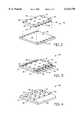
- FIG. 1Ais a partial cut away isometric view of a conventional ball grid array device, and FIG. 1B is an isometric view of the bottom of the FIG. 1A device depicting solder balls on the substrate;
- FIG. 2is an exploded isometric view depicting an assembly step for forming one embodiment of the invention
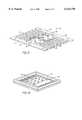
- FIG. 3is an isometric view depicting a partially assembled inventive embodiment
- FIG. 4is an isometric view depicting a completed embodiment of the invention.
- FIG. 5is an isometric view depicting a frame for use with the inventive embodiment.
- FIG. 6is an isometric view depicting an inventive embodiment comprising a molded carrier ring.
- FIG. 2depicts an assembly step used to form a first embodiment of an inventive ball grid array (BGA) device, illustrated generally at 26.
- Device 26comprises a conventional semiconductor die 14 or other wafer section, as depicted relative to the embodiment of FIG. 1, having exposed bond pads 16 laterally located on a major surface 28 (circuit side) of the die.
- the dieAs depicted in FIG. 2, the wafer section 14 is generally planar across the major surface 14 includes a polyimide passivating layer or another passivating material (not individually illustrated) formed over the circuit side 28 of the die.
- Various polyimide and other nonconductive passivating layersare known to those skilled in the art. The bond pads remain unpassivated.
- Interconnection assembly 30is utilized to establish contact between bond pads 16 of die 14 and contact balls, bumps, leads or other contacts illustrated as balls 42 in FIG. 4.
- Interconnection assembly 30comprises a plurality of conductors (depicted unencapsulated in FIG. 5 as 52) each of which extends from a first location 32 to a second location 34.
- the first location 32is configured to facilitate electrical coupling to bond pads 16, and the second location 34 is configured to facilitate electrical coupling to the contacts 42.
- the interconnection assembly 30further comprises an insulation matrix 36 supporting a portion of each conductor 52.
- the electrically-insulating matrix 36 of the instant embodimentcan comprise generally any conventional thermoset die encapsulation resins or plastics. Ideal qualities of the matrix include a material that is noncorrosive, chemically stable, thermally conductive, and electrically nonconductive.
- each conductorcomprises a lead section exposed at the first end 32 which can be flush with or extend beyond the adjacent surface of matrix 36.
- Each conductorextends through the matrix and terminates in an exposed pad portion at the second end 34 on an exterior surface 31 of the matrix 36.
- the conductors 52each comprise a portion encased in matrix 36 and a portion 32, 34 free from the matrix.
- the second end 34 of each conductor 52comprises a planar surface which is generally parallel with a plane of the circuit side 28 of die 14.
- the exposed second ends 34 of the FIG. 3 embodimentare arranged in a 4 ⁇ 3 grid.
- the interconnection assembly 30is attached to the major surface 28 of the die 14 as depicted in FIG. 3 using a nonconductive die attach material (not depicted).
- a nonconductive die attach material(not depicted).
- Myriad nonconductive die attach materialsare available, and sufficient die attach materials suitable for use with the instant invention would be recognized by one of ordinary skill in the art.
- At least one lead section 32is then electrically coupled with a respective bond pad 16 as depicted in FIG. 3, for example using a bond wire 38. More preferably, a plurality of lead sections are each coupled with a respective bond pad as depicted in FIG. 3. Connection methods other than bond wires may also function adequately.
- connection methodsinclude extending the leads and aligning them vertically with the bond pads and using a Z-axis conductive material to electrically couple the bond pads and leads, or using tape automated bonding connections to couple the leads and bond pads. Some of the bond pads may not be connected with leads, depending on the various bond options selected and eventual use of the device.
- the interconnection assembly 30can be connected to the die 14 at only the matrix portions, at only the exposed conductor portions, or at both the matrix and conductor portions.
- "attaching" the interconnection assembly 30 to the die 14includes connecting the conductors 52 to the die regardless of whether attach material is formed between the die and the conductors.
- the interconnection assembly 30has leads protruding from first 33 and second 35 opposite surfaces of the matrix 36.
- the assemblyfurther comprises a third surface 37 connected to the die 14. Second ends 34 of the conductors are exposed at a fourth surface 31 opposite the third surface 37.
- the noncircuit side of the semiconductor dieremains exposed which allows for the efficient dissipation of heat from the die.
- FIG. 3further depicts that the circuit side 28 of the die 14 which comprises the bond pads 16 faces the solder balls 42 while the back side of the die faces away from the solder balls.
- the circuit side 28 of the die 14is closer to the solder balls 42 than is the back side of the die. This is in contrast to the related art embodiment depicted in FIG. 1 wherein the bond pads 16 face away from the solder balls 12.
- the FIG. 3 structureis generally an in-process apparatus wherein the bond wires 38, leads 32, and bond pads 16 remain exposed after wire bonding.
- a sealing material 40is dispensed to contact these exposed elements as depicted in FIG. 4 and to protect the device from environmental damage.
- Sealing materialswhich would provide adequate protection and which would adhere adequately to the die and to the interconnection assembly include conventional glob-top material such as 4450 Hysol by Dexter Electronics, 2111 Tracon by Tracon Co., or Ablebond products by Ablestick.
- the sealing materialcan be dispensed by any sufficient means including syringe dispensing, stenciling, silk screen, globbing, or using encapsulation techniques. In some uses of this embodiment the sealing material may not be necessary.
- the second ends 34 of the conductors which terminate on the exterior of the interconnection assembly 30can be bumped 42 with solder or another conductive interconnect material to provide a means for coupling with pads on a PCB or other assembly.
- solder or another conductive interconnect materialPrior to bumping, necessary plating material can be formed to provide the desired under-bump metalization (UBM) for the solder balls.
- UBMunder-bump metalization
- the connection between the package and the receiving assemblycan be supplied using an interconnect such as Z-axis conductor, through the use of an interconnect such as a socket assembly having contacts that provide communication with the die, or through other interconnections.
- FIG. 5depicts one possible lead frame 50 comprising conductors 52 with first 32 and second 34 ends depicted.
- the frame 50 of FIG. 5is depicted before formation of the matrix 36 of FIG. 2, and before severing lead frame rails 54 and dam bars 56.
- the frame of FIG. 5is placed in a mold such as a transfer, injection, or compression mold and the insulation material is formed around the conductors. The frame is removed and the scrap metal is trimmed and the excess plastic is removed.
- the frame of FIG. 5will form an interconnection assembly (30, FIG. 2) having exposed pads 34 arranged in a 4 ⁇ 3 grid.
- An advantage of the instant embodimentis that the leads of the interconnection assembly 30 terminate within the perimeter of the die 14 as depicted in FIG. 2. This provides a package that requires no more lateral space on a PCB than the die itself, thereby decreasing the space required for the package over conventional BGA devices as depicted in FIG. 1.
- the instant inventionmay also be applied to die having bond pads laterally located along any or all of one, two, three, or four sides, or bond pads centrally located on the die. Further, a variety of arrangements of conductors within the matrix can be provided. Additionally, the conductors 52 in interconnection assembly 30 may be arranged in any of a number of desired patterns. For example, the second ends can be exposed in a grid pattern or along any or all edges of the interconnect. Further, first ends 32 of the frame 52 may extend beyond the matrix 36 as illustrated in FIG. 2, or they may terminate flush with the surface of matrix 36.
- the second ends 34 of the conductorsmay further terminate in conductive pins that protrude from the surface of the matrix 36, or pins (leads) can be assembled onto the second ends 34 of the conductors, for example by soldering pins to the second ends.
- Either of ends 32 or 34may be covered by matrix 36 as long as electrical connection therewith is possible, such as by a contact which pierces the matrix over the end to make electrical contact with the underlying end.
- FIG. 6depicts an embodiment comprising a molded carrier ring (MCR) 60 which aids in the handling and testing the packaged device.
- MCRmolded carrier ring
- the lead portions 62 that protrude from the sealing material 40can be severed flush with the sealing material.
- the leads 62can be formed and electrical contact between the die and the PCB to which the die is attached can be made through the leads at the first ends 32 of the conductors 52, rather than through the conductor portions at the second ends 34. Forming a device with protruding leads 62 would require rerouting of the leads from the configuration depicted in FIG. 3 to allow for forming bond wires. Otherwise, the leads will cover the bond pads thereby preventing wire bonding.
- the Z-axis conductor described previouslycan be used, or the leads can be routed near the bond pads to allow for wire bonding and routed out the package near the ends of the die having no bond pads.
- the leadscould also be narrowed to allow for routing between the bond pads as long as at least a portion of the leads are of sufficient size to provide a surface for wire bonding.
- Alternate methods for forming the device of FIGS. 2 and 3include attaching an interconnect 30 to each die of an undiced semiconductor wafer.
- the wafercan be diced at this point and the wire bonding performed after dicing, or the bond wires can be attached to the bond pads and to the leads of each interconnect before dicing the wafer.
- the sealing materialcan be formed to seal the bond pads, bond wires, and the exposed lead portions either before or after dicing the wafer.
- a plurality of undiced semiconductor diefor example eight die, are connected with an interconnect having locations for eight die in the manner described above to form a semiconductor module.
- a number of individual diecan be connected with one electrical interconnect having locations for a plurality of die to form a module.
- Such a modulecould include a combination of device types, such as one or more microprocessors in combination with memory and/or logic devices.
- first ends 32 of the connectors 52are flush with the matrix 36.
- the electrical connection that electrically couples the first ends 32 of the conductors with the bond pads 16 on the die 14can include tape automated bonding, wire bonding, or the formation of another type of conductive layer. Other first-end terminations can be formed depending on the individual design or particular use of the instant invention.
- a semiconductor device comprising the inventioncould conceivably be attached along with other devices to a printed circuit board, for example to a computer motherboard or as a part of a memory module used in a personal computer, a minicomputer, or a mainframe.
- the inventive devicecould further be useful in other electronic devices related to telecommunications, the automobile industry, semiconductor test and manufacturing equipment, consumer electronics, or virtually any piece of consumer or industrial electronic equipment.
Landscapes
- Physics & Mathematics (AREA)
- Condensed Matter Physics & Semiconductors (AREA)
- General Physics & Mathematics (AREA)
- Engineering & Computer Science (AREA)
- Computer Hardware Design (AREA)
- Microelectronics & Electronic Packaging (AREA)
- Power Engineering (AREA)
- Wire Bonding (AREA)
Abstract
Description
Claims (23)
Priority Applications (3)
| Application Number | Priority Date | Filing Date | Title |
|---|---|---|---|
| US09/121,272US6114770A (en) | 1998-07-22 | 1998-07-22 | Low profile semiconductor package |
| US09/655,034US6495400B1 (en) | 1998-07-22 | 2000-09-05 | Method of forming low profile semiconductor package |
| US10/322,119US6669738B2 (en) | 1998-07-22 | 2002-12-16 | Low profile semiconductor package |
Applications Claiming Priority (1)
| Application Number | Priority Date | Filing Date | Title |
|---|---|---|---|
| US09/121,272US6114770A (en) | 1998-07-22 | 1998-07-22 | Low profile semiconductor package |
Related Child Applications (1)
| Application Number | Title | Priority Date | Filing Date |
|---|---|---|---|
| US09/655,034DivisionUS6495400B1 (en) | 1998-07-22 | 2000-09-05 | Method of forming low profile semiconductor package |
Publications (1)
| Publication Number | Publication Date |
|---|---|
| US6114770Atrue US6114770A (en) | 2000-09-05 |
Family
ID=22395613
Family Applications (3)
| Application Number | Title | Priority Date | Filing Date |
|---|---|---|---|
| US09/121,272Expired - LifetimeUS6114770A (en) | 1998-07-22 | 1998-07-22 | Low profile semiconductor package |
| US09/655,034Expired - LifetimeUS6495400B1 (en) | 1998-07-22 | 2000-09-05 | Method of forming low profile semiconductor package |
| US10/322,119Expired - LifetimeUS6669738B2 (en) | 1998-07-22 | 2002-12-16 | Low profile semiconductor package |
Family Applications After (2)
| Application Number | Title | Priority Date | Filing Date |
|---|---|---|---|
| US09/655,034Expired - LifetimeUS6495400B1 (en) | 1998-07-22 | 2000-09-05 | Method of forming low profile semiconductor package |
| US10/322,119Expired - LifetimeUS6669738B2 (en) | 1998-07-22 | 2002-12-16 | Low profile semiconductor package |
Country Status (1)
| Country | Link |
|---|---|
| US (3) | US6114770A (en) |
Cited By (8)
| Publication number | Priority date | Publication date | Assignee | Title |
|---|---|---|---|---|
| US6716670B1 (en) | 2002-01-09 | 2004-04-06 | Bridge Semiconductor Corporation | Method of forming a three-dimensional stacked semiconductor package device |
| US6936495B1 (en) | 2002-01-09 | 2005-08-30 | Bridge Semiconductor Corporation | Method of making an optoelectronic semiconductor package device |
| US20050251586A1 (en)* | 1999-02-08 | 2005-11-10 | Megic Corporation | Multiple selectable function integrated circuit module |
| US6987034B1 (en) | 2002-01-09 | 2006-01-17 | Bridge Semiconductor Corporation | Method of making a semiconductor package device that includes singulating and trimming a lead |
| US7190060B1 (en) | 2002-01-09 | 2007-03-13 | Bridge Semiconductor Corporation | Three-dimensional stacked semiconductor package device with bent and flat leads and method of making same |
| US20090102030A1 (en)* | 2007-10-22 | 2009-04-23 | Broadcom Corporation | Integrated circuit package with etched leadframe for package-on-package interconnects |
| US7659504B1 (en)* | 2005-05-18 | 2010-02-09 | Ric Investments, Llc | Optical sensor with an optical element transmissive to warming radiation |
| CN104465593A (en)* | 2014-11-13 | 2015-03-25 | 苏州日月新半导体有限公司 | Semiconductor package and packaging method |
Families Citing this family (3)
| Publication number | Priority date | Publication date | Assignee | Title |
|---|---|---|---|---|
| US6664615B1 (en)* | 2001-11-20 | 2003-12-16 | National Semiconductor Corporation | Method and apparatus for lead-frame based grid array IC packaging |
| US8022516B2 (en)* | 2008-08-13 | 2011-09-20 | Atmel Corporation | Metal leadframe package with secure feature |
| US8674504B2 (en)* | 2012-05-21 | 2014-03-18 | Texas Systems Incorporated | Wire-based methodology of widening the pitch of semiconductor chip terminals |
Citations (11)
| Publication number | Priority date | Publication date | Assignee | Title |
|---|---|---|---|---|
| US3663868A (en)* | 1969-10-17 | 1972-05-16 | Nippon Electric Co | Hermetically sealed semiconductor device |
| US4622574A (en)* | 1985-07-29 | 1986-11-11 | The Perkin-Elmer Corporation | Semiconductor chip with recessed bond pads |
| US4901136A (en)* | 1987-07-14 | 1990-02-13 | General Electric Company | Multi-chip interconnection package |
| US4922324A (en)* | 1987-01-20 | 1990-05-01 | Kabushiki Kaisha Toshiba | Semiconductor integrated circuit device |
| US5045921A (en)* | 1989-12-26 | 1991-09-03 | Motorola, Inc. | Pad array carrier IC device using flexible tape |
| US5218234A (en)* | 1991-12-23 | 1993-06-08 | Motorola, Inc. | Semiconductor device with controlled spread polymeric underfill |
| US5241133A (en)* | 1990-12-21 | 1993-08-31 | Motorola, Inc. | Leadless pad array chip carrier |
| US5302849A (en)* | 1993-03-01 | 1994-04-12 | Motorola, Inc. | Plastic and grid array semiconductor device and method for making the same |
| US5360992A (en)* | 1991-12-20 | 1994-11-01 | Micron Technology, Inc. | Two piece assembly for the selection of pinouts and bond options on a semiconductor device |
| US5583378A (en)* | 1994-05-16 | 1996-12-10 | Amkor Electronics, Inc. | Ball grid array integrated circuit package with thermal conductor |
| US5753974A (en)* | 1994-09-12 | 1998-05-19 | Nec Corporation | Electronic device assembly |
- 1998
- 1998-07-22USUS09/121,272patent/US6114770A/ennot_activeExpired - Lifetime
- 2000
- 2000-09-05USUS09/655,034patent/US6495400B1/ennot_activeExpired - Lifetime
- 2002
- 2002-12-16USUS10/322,119patent/US6669738B2/ennot_activeExpired - Lifetime
Patent Citations (11)
| Publication number | Priority date | Publication date | Assignee | Title |
|---|---|---|---|---|
| US3663868A (en)* | 1969-10-17 | 1972-05-16 | Nippon Electric Co | Hermetically sealed semiconductor device |
| US4622574A (en)* | 1985-07-29 | 1986-11-11 | The Perkin-Elmer Corporation | Semiconductor chip with recessed bond pads |
| US4922324A (en)* | 1987-01-20 | 1990-05-01 | Kabushiki Kaisha Toshiba | Semiconductor integrated circuit device |
| US4901136A (en)* | 1987-07-14 | 1990-02-13 | General Electric Company | Multi-chip interconnection package |
| US5045921A (en)* | 1989-12-26 | 1991-09-03 | Motorola, Inc. | Pad array carrier IC device using flexible tape |
| US5241133A (en)* | 1990-12-21 | 1993-08-31 | Motorola, Inc. | Leadless pad array chip carrier |
| US5360992A (en)* | 1991-12-20 | 1994-11-01 | Micron Technology, Inc. | Two piece assembly for the selection of pinouts and bond options on a semiconductor device |
| US5218234A (en)* | 1991-12-23 | 1993-06-08 | Motorola, Inc. | Semiconductor device with controlled spread polymeric underfill |
| US5302849A (en)* | 1993-03-01 | 1994-04-12 | Motorola, Inc. | Plastic and grid array semiconductor device and method for making the same |
| US5583378A (en)* | 1994-05-16 | 1996-12-10 | Amkor Electronics, Inc. | Ball grid array integrated circuit package with thermal conductor |
| US5753974A (en)* | 1994-09-12 | 1998-05-19 | Nec Corporation | Electronic device assembly |
Non-Patent Citations (2)
| Title |
|---|
| "Z-Axis Conductive Adhesive", Zymet Inc., 7 Great Meadow Lane, E. Hanover, NJ 07936, Aug. 1, 1990. |
| Z Axis Conductive Adhesive , Zymet Inc., 7 Great Meadow Lane, E. Hanover, NJ 07936, Aug. 1, 1990.* |
Cited By (24)
| Publication number | Priority date | Publication date | Assignee | Title |
|---|---|---|---|---|
| US7372162B2 (en)* | 1999-02-08 | 2008-05-13 | Megica Corporation | Multiple selectable function integrated circuit module |
| US20050251586A1 (en)* | 1999-02-08 | 2005-11-10 | Megic Corporation | Multiple selectable function integrated circuit module |
| US8471389B2 (en)* | 1999-02-08 | 2013-06-25 | Megica Corporation | Multiple selectable function integrated circuit module |
| US20110285018A1 (en)* | 1999-02-08 | 2011-11-24 | Megica Corporation | Multiple selectable function integrated circuit module |
| US8013448B2 (en) | 1999-02-08 | 2011-09-06 | Megica Corporation | Multiple selectable function integrated circuit module |
| US20080185736A1 (en)* | 1999-02-08 | 2008-08-07 | Megica Corporation | Multiple selectable function integrated circuit module |
| US7190060B1 (en) | 2002-01-09 | 2007-03-13 | Bridge Semiconductor Corporation | Three-dimensional stacked semiconductor package device with bent and flat leads and method of making same |
| US6891276B1 (en)* | 2002-01-09 | 2005-05-10 | Bridge Semiconductor Corporation | Semiconductor package device |
| US6989584B1 (en) | 2002-01-09 | 2006-01-24 | Bridge Semiconductor Corporation | Semiconductor package device that includes a conductive trace with a routing line, a terminal and a lead |
| US6989295B1 (en) | 2002-01-09 | 2006-01-24 | Bridge Semiconductor Corporation | Method of making a semiconductor package device that includes an insulative housing with first and second housing portions |
| US6774659B1 (en)* | 2002-01-09 | 2004-08-10 | Bridge Semiconductor Corporation | Method of testing a semiconductor package device |
| US7009309B1 (en) | 2002-01-09 | 2006-03-07 | Bridge Semiconductor Corporation | Semiconductor package device that includes an insulative housing with a protruding peripheral portion |
| US6803651B1 (en) | 2002-01-09 | 2004-10-12 | Bridge Semiconductor Corporation | Optoelectronic semiconductor package device |
| US6936495B1 (en) | 2002-01-09 | 2005-08-30 | Bridge Semiconductor Corporation | Method of making an optoelectronic semiconductor package device |
| US6987034B1 (en) | 2002-01-09 | 2006-01-17 | Bridge Semiconductor Corporation | Method of making a semiconductor package device that includes singulating and trimming a lead |
| US6908794B1 (en) | 2002-01-09 | 2005-06-21 | Bridge Semiconductor Corporation | Method of making a semiconductor package device that includes a conductive trace with recessed and non-recessed portions |
| US6716670B1 (en) | 2002-01-09 | 2004-04-06 | Bridge Semiconductor Corporation | Method of forming a three-dimensional stacked semiconductor package device |
| US7659504B1 (en)* | 2005-05-18 | 2010-02-09 | Ric Investments, Llc | Optical sensor with an optical element transmissive to warming radiation |
| US7618849B2 (en)* | 2007-10-22 | 2009-11-17 | Broadcom Corporation | Integrated circuit package with etched leadframe for package-on-package interconnects |
| US20090102030A1 (en)* | 2007-10-22 | 2009-04-23 | Broadcom Corporation | Integrated circuit package with etched leadframe for package-on-package interconnects |
| US8269323B2 (en)* | 2007-10-22 | 2012-09-18 | Broadcom Corporation | Integrated circuit package with etched leadframe for package-on-package interconnects |
| US20100019360A1 (en)* | 2007-10-22 | 2010-01-28 | Broadcom Corporation | Integrated circuit package with etched leadframe for package-on-package interconnects |
| CN104465593A (en)* | 2014-11-13 | 2015-03-25 | 苏州日月新半导体有限公司 | Semiconductor package and packaging method |
| CN104465593B (en)* | 2014-11-13 | 2018-10-19 | 苏州日月新半导体有限公司 | Semiconductor package and packaging method |
Also Published As
| Publication number | Publication date |
|---|---|
| US20030085459A1 (en) | 2003-05-08 |
| US6495400B1 (en) | 2002-12-17 |
| US6669738B2 (en) | 2003-12-30 |
Similar Documents
| Publication | Publication Date | Title |
|---|---|---|
| US6414391B1 (en) | Module assembly for stacked BGA packages with a common bus bar in the assembly | |
| US5942795A (en) | Leaded substrate carrier for integrated circuit device and leaded substrate carrier device assembly | |
| US5291062A (en) | Area array semiconductor device having a lid with functional contacts | |
| US6667556B2 (en) | Flip chip adaptor package for bare die | |
| US6531337B1 (en) | Method of manufacturing a semiconductor structure having stacked semiconductor devices | |
| US6861290B1 (en) | Flip-chip adaptor package for bare die | |
| US5627405A (en) | Integrated circuit assembly incorporating an anisotropic elecctrically conductive layer | |
| US7573136B2 (en) | Semiconductor device assemblies and packages including multiple semiconductor device components | |
| US20060194373A1 (en) | Methods for assembling semiconductor devices and interposers | |
| US20030000082A1 (en) | IC package with dual heat spreaders | |
| US20030230801A1 (en) | Semiconductor device assemblies and packages including multiple semiconductor devices and methods | |
| US20010013654A1 (en) | Ball grid package with multiple power/ ground planes | |
| US20150076679A1 (en) | Semiconductor device assemblies including face-to-face semiconductor dice and related methods | |
| JP2895022B2 (en) | Manufacturing method of chip scale package | |
| US6114770A (en) | Low profile semiconductor package | |
| KR101096330B1 (en) | Package for Semiconductor Devices | |
| JPH04273451A (en) | Semiconductor device | |
| US5559305A (en) | Semiconductor package having adjacently arranged semiconductor chips | |
| EP0413542A2 (en) | Direct mount semiconductor package | |
| JP2822990B2 (en) | CSP type semiconductor device |
Legal Events
| Date | Code | Title | Description |
|---|---|---|---|
| AS | Assignment | Owner name:MICRON TECHNOLOGY, INC., IDAHO Free format text:ASSIGNMENT OF ASSIGNORS INTEREST;ASSIGNORS:AKRAM, SALMAN;KNGSMAN, LARRY;REEL/FRAME:009339/0005;SIGNING DATES FROM 19980717 TO 19980722 | |
| STCF | Information on status: patent grant | Free format text:PATENTED CASE | |
| FPAY | Fee payment | Year of fee payment:4 | |
| FPAY | Fee payment | Year of fee payment:8 | |
| FPAY | Fee payment | Year of fee payment:12 | |
| AS | Assignment | Owner name:U.S. BANK NATIONAL ASSOCIATION, AS COLLATERAL AGENT, CALIFORNIA Free format text:SECURITY INTEREST;ASSIGNOR:MICRON TECHNOLOGY, INC.;REEL/FRAME:038669/0001 Effective date:20160426 Owner name:U.S. BANK NATIONAL ASSOCIATION, AS COLLATERAL AGEN Free format text:SECURITY INTEREST;ASSIGNOR:MICRON TECHNOLOGY, INC.;REEL/FRAME:038669/0001 Effective date:20160426 | |
| AS | Assignment | Owner name:MORGAN STANLEY SENIOR FUNDING, INC., AS COLLATERAL AGENT, MARYLAND Free format text:PATENT SECURITY AGREEMENT;ASSIGNOR:MICRON TECHNOLOGY, INC.;REEL/FRAME:038954/0001 Effective date:20160426 Owner name:MORGAN STANLEY SENIOR FUNDING, INC., AS COLLATERAL Free format text:PATENT SECURITY AGREEMENT;ASSIGNOR:MICRON TECHNOLOGY, INC.;REEL/FRAME:038954/0001 Effective date:20160426 | |
| AS | Assignment | Owner name:U.S. BANK NATIONAL ASSOCIATION, AS COLLATERAL AGENT, CALIFORNIA Free format text:CORRECTIVE ASSIGNMENT TO CORRECT THE REPLACE ERRONEOUSLY FILED PATENT #7358718 WITH THE CORRECT PATENT #7358178 PREVIOUSLY RECORDED ON REEL 038669 FRAME 0001. ASSIGNOR(S) HEREBY CONFIRMS THE SECURITY INTEREST;ASSIGNOR:MICRON TECHNOLOGY, INC.;REEL/FRAME:043079/0001 Effective date:20160426 Owner name:U.S. BANK NATIONAL ASSOCIATION, AS COLLATERAL AGEN Free format text:CORRECTIVE ASSIGNMENT TO CORRECT THE REPLACE ERRONEOUSLY FILED PATENT #7358718 WITH THE CORRECT PATENT #7358178 PREVIOUSLY RECORDED ON REEL 038669 FRAME 0001. ASSIGNOR(S) HEREBY CONFIRMS THE SECURITY INTEREST;ASSIGNOR:MICRON TECHNOLOGY, INC.;REEL/FRAME:043079/0001 Effective date:20160426 | |
| AS | Assignment | Owner name:JPMORGAN CHASE BANK, N.A., AS COLLATERAL AGENT, ILLINOIS Free format text:SECURITY INTEREST;ASSIGNORS:MICRON TECHNOLOGY, INC.;MICRON SEMICONDUCTOR PRODUCTS, INC.;REEL/FRAME:047540/0001 Effective date:20180703 Owner name:JPMORGAN CHASE BANK, N.A., AS COLLATERAL AGENT, IL Free format text:SECURITY INTEREST;ASSIGNORS:MICRON TECHNOLOGY, INC.;MICRON SEMICONDUCTOR PRODUCTS, INC.;REEL/FRAME:047540/0001 Effective date:20180703 | |
| AS | Assignment | Owner name:MICRON TECHNOLOGY, INC., IDAHO Free format text:RELEASE BY SECURED PARTY;ASSIGNOR:U.S. BANK NATIONAL ASSOCIATION, AS COLLATERAL AGENT;REEL/FRAME:047243/0001 Effective date:20180629 | |
| AS | Assignment | Owner name:MICRON TECHNOLOGY, INC., IDAHO Free format text:RELEASE BY SECURED PARTY;ASSIGNOR:MORGAN STANLEY SENIOR FUNDING, INC., AS COLLATERAL AGENT;REEL/FRAME:050937/0001 Effective date:20190731 | |
| AS | Assignment | Owner name:MICRON SEMICONDUCTOR PRODUCTS, INC., IDAHO Free format text:RELEASE BY SECURED PARTY;ASSIGNOR:JPMORGAN CHASE BANK, N.A., AS COLLATERAL AGENT;REEL/FRAME:051028/0001 Effective date:20190731 Owner name:MICRON TECHNOLOGY, INC., IDAHO Free format text:RELEASE BY SECURED PARTY;ASSIGNOR:JPMORGAN CHASE BANK, N.A., AS COLLATERAL AGENT;REEL/FRAME:051028/0001 Effective date:20190731 |