US6113823A - Pyrolytic carbon transmyocardial implant - Google Patents
Pyrolytic carbon transmyocardial implantDownload PDFInfo
- Publication number
- US6113823A US6113823AUS09/094,136US9413698AUS6113823AUS 6113823 AUS6113823 AUS 6113823AUS 9413698 AUS9413698 AUS 9413698AUS 6113823 AUS6113823 AUS 6113823A
- Authority
- US
- United States
- Prior art keywords
- pyrolytic carbon
- master
- conduit
- geometry
- external surface
- Prior art date
- Legal status (The legal status is an assumption and is not a legal conclusion. Google has not performed a legal analysis and makes no representation as to the accuracy of the status listed.)
- Expired - Fee Related
Links
Images

Classifications
- A—HUMAN NECESSITIES
- A61—MEDICAL OR VETERINARY SCIENCE; HYGIENE
- A61L—METHODS OR APPARATUS FOR STERILISING MATERIALS OR OBJECTS IN GENERAL; DISINFECTION, STERILISATION OR DEODORISATION OF AIR; CHEMICAL ASPECTS OF BANDAGES, DRESSINGS, ABSORBENT PADS OR SURGICAL ARTICLES; MATERIALS FOR BANDAGES, DRESSINGS, ABSORBENT PADS OR SURGICAL ARTICLES
- A61L33/00—Antithrombogenic treatment of surgical articles, e.g. sutures, catheters, prostheses, or of articles for the manipulation or conditioning of blood; Materials for such treatment
- A61L33/02—Use of inorganic materials
- A61L33/025—Carbon; Graphite
- A—HUMAN NECESSITIES
- A61—MEDICAL OR VETERINARY SCIENCE; HYGIENE
- A61F—FILTERS IMPLANTABLE INTO BLOOD VESSELS; PROSTHESES; DEVICES PROVIDING PATENCY TO, OR PREVENTING COLLAPSING OF, TUBULAR STRUCTURES OF THE BODY, e.g. STENTS; ORTHOPAEDIC, NURSING OR CONTRACEPTIVE DEVICES; FOMENTATION; TREATMENT OR PROTECTION OF EYES OR EARS; BANDAGES, DRESSINGS OR ABSORBENT PADS; FIRST-AID KITS
- A61F2/00—Filters implantable into blood vessels; Prostheses, i.e. artificial substitutes or replacements for parts of the body; Appliances for connecting them with the body; Devices providing patency to, or preventing collapsing of, tubular structures of the body, e.g. stents
- A61F2/02—Prostheses implantable into the body
- A61F2/04—Hollow or tubular parts of organs, e.g. bladders, tracheae, bronchi or bile ducts
- A61F2/06—Blood vessels
- A61F2/064—Blood vessels with special features to facilitate anastomotic coupling
- A—HUMAN NECESSITIES
- A61—MEDICAL OR VETERINARY SCIENCE; HYGIENE
- A61L—METHODS OR APPARATUS FOR STERILISING MATERIALS OR OBJECTS IN GENERAL; DISINFECTION, STERILISATION OR DEODORISATION OF AIR; CHEMICAL ASPECTS OF BANDAGES, DRESSINGS, ABSORBENT PADS OR SURGICAL ARTICLES; MATERIALS FOR BANDAGES, DRESSINGS, ABSORBENT PADS OR SURGICAL ARTICLES
- A61L27/00—Materials for grafts or prostheses or for coating grafts or prostheses
- A61L27/02—Inorganic materials
- A61L27/08—Carbon ; Graphite
- A—HUMAN NECESSITIES
- A61—MEDICAL OR VETERINARY SCIENCE; HYGIENE
- A61L—METHODS OR APPARATUS FOR STERILISING MATERIALS OR OBJECTS IN GENERAL; DISINFECTION, STERILISATION OR DEODORISATION OF AIR; CHEMICAL ASPECTS OF BANDAGES, DRESSINGS, ABSORBENT PADS OR SURGICAL ARTICLES; MATERIALS FOR BANDAGES, DRESSINGS, ABSORBENT PADS OR SURGICAL ARTICLES
- A61L27/00—Materials for grafts or prostheses or for coating grafts or prostheses
- A61L27/28—Materials for coating prostheses
- A61L27/30—Inorganic materials
- A61L27/303—Carbon
- A—HUMAN NECESSITIES
- A61—MEDICAL OR VETERINARY SCIENCE; HYGIENE
- A61L—METHODS OR APPARATUS FOR STERILISING MATERIALS OR OBJECTS IN GENERAL; DISINFECTION, STERILISATION OR DEODORISATION OF AIR; CHEMICAL ASPECTS OF BANDAGES, DRESSINGS, ABSORBENT PADS OR SURGICAL ARTICLES; MATERIALS FOR BANDAGES, DRESSINGS, ABSORBENT PADS OR SURGICAL ARTICLES
- A61L31/00—Materials for other surgical articles, e.g. stents, stent-grafts, shunts, surgical drapes, guide wires, materials for adhesion prevention, occluding devices, surgical gloves, tissue fixation devices
- A61L31/02—Inorganic materials
- A61L31/024—Carbon; Graphite
- A—HUMAN NECESSITIES
- A61—MEDICAL OR VETERINARY SCIENCE; HYGIENE
- A61L—METHODS OR APPARATUS FOR STERILISING MATERIALS OR OBJECTS IN GENERAL; DISINFECTION, STERILISATION OR DEODORISATION OF AIR; CHEMICAL ASPECTS OF BANDAGES, DRESSINGS, ABSORBENT PADS OR SURGICAL ARTICLES; MATERIALS FOR BANDAGES, DRESSINGS, ABSORBENT PADS OR SURGICAL ARTICLES
- A61L31/00—Materials for other surgical articles, e.g. stents, stent-grafts, shunts, surgical drapes, guide wires, materials for adhesion prevention, occluding devices, surgical gloves, tissue fixation devices
- A61L31/08—Materials for coatings
- A61L31/082—Inorganic materials
- A61L31/084—Carbon; Graphite
- Y—GENERAL TAGGING OF NEW TECHNOLOGICAL DEVELOPMENTS; GENERAL TAGGING OF CROSS-SECTIONAL TECHNOLOGIES SPANNING OVER SEVERAL SECTIONS OF THE IPC; TECHNICAL SUBJECTS COVERED BY FORMER USPC CROSS-REFERENCE ART COLLECTIONS [XRACs] AND DIGESTS
- Y10—TECHNICAL SUBJECTS COVERED BY FORMER USPC
- Y10S—TECHNICAL SUBJECTS COVERED BY FORMER USPC CROSS-REFERENCE ART COLLECTIONS [XRACs] AND DIGESTS
- Y10S264/00—Plastic and nonmetallic article shaping or treating: processes
- Y10S264/51—Use of fluidized bed in molding
- Y—GENERAL TAGGING OF NEW TECHNOLOGICAL DEVELOPMENTS; GENERAL TAGGING OF CROSS-SECTIONAL TECHNOLOGIES SPANNING OVER SEVERAL SECTIONS OF THE IPC; TECHNICAL SUBJECTS COVERED BY FORMER USPC CROSS-REFERENCE ART COLLECTIONS [XRACs] AND DIGESTS
- Y10—TECHNICAL SUBJECTS COVERED BY FORMER USPC
- Y10S—TECHNICAL SUBJECTS COVERED BY FORMER USPC CROSS-REFERENCE ART COLLECTIONS [XRACs] AND DIGESTS
- Y10S623/00—Prosthesis, i.e. artificial body members, parts thereof, or aids and accessories therefor
- Y10S623/901—Method of manufacturing prosthetic device
Definitions
- This inventionpertains to an implant for passing blood flow directly between a chamber of the heart and a coronary vessel. More particularly, this invention pertains to such an implant formed of pyrolytic carbon and a method of making such an implant.
- An embodiment disclosed in the aforementioned applicationteaches an L-shaped implant in the form of a rigid conduit having one leg sized to be received within a lumen of a coronary artery and a second leg sized to pass through the myocardium and extend into the left ventricle of the heart.
- the conduitis rigid and remains open for blood flow to pass through the conduit during both systole and diastole. The conduit penetrates into the left ventricle in order to prevent tissue growth and occlusions over an opening of the conduit.
- Implants such as those shown in the aforementioned applicationsinclude a portion to be placed within a coronary vessel and a portion to be placed within the myocardium. Such implants may be made of titanium. Titanium has a long history for use as an implant material in contact with blood. For example, titanium is used as a material in heart valves because it is thrombo-resistant.
- pyrolytic carbonAnother desirable material for use in blood-contacting implants is pyrolytic carbon. Long used in heart valves, pyrolytic carbon is biocompatible and thrombo-resistant.
- pyrolytic carbonis used to coat the external, blood contacting surfaces component parts.
- a partsuch as a valve leaflet, is first formed of a substrate material with dimensions smaller than the desired part but conforming in geometry to the desired part.
- a common substrate materialis graphite because pyrolytic carbon adheres to graphite and graphite is resistant to thermal expansion and can tolerate the extreme temperatures experienced when applying pyrolytic carbon.
- the graphite substrateis placed in a fluidized bed reactor with a reaction zone having temperatures of about 1,300° C.
- Propane gasis used as a carbon source.
- the carbonis deposited on the external surface of the part as pyrolytic carbon.
- the coatingcontinues for a time selected to achieve a desired thickness of the pyrolytic carbon so that the final part has a size approximate to the desired size of the part.
- the pyrolytic carbon layerassumes the geometry of the external surface of the graphite substrate. If necessary the pyrolytic carbon can be machined.
- the afore-said applicationsdisclose the desirability of a pyrolytic or pyrolytic-coated titanium implant.
- the interior surface of such an implantshould be pyrolytic carbon as opposed to the external surfaces of valve components.
- the afore-mentioned process for coating external surfaces with pyrolytic carbondo not suggest how to form an implant with an internal surface of pyrolytic carbon.
- a typical such implanthas a curved interior surface further frustrating attempts to fabricate or coat the implant with pyrolytic carbon.
- the long, narrow (i.e., the diameter is less than the length) blood flow pathfrustrates attempts to so fabricate or coat.
- a methodfor forming a by-pass conduit having a desired hollow internal geometry for defining a bounded blood flow path from an open first end positioned in a heart chamber and an open second end connected to a lumen of a coronary vessel.
- the methodcomprises forming a master having an external surface with an external geometry complementary to the desired internal geometry of the conduit.
- the external surface of the masteris coated with pyrolytic carbon to define a pyrolytic carbon conduit of pyrolytic carbon bonded to the external surface of the master and with the pyrolytic carbon having an internal surface with a conduit geometry complementary to the external geometry of the master.
- the masteris removed from the pyrolytic carbon conduit.
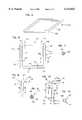
- FIG. 1is a perspective view of a graphite block for use in forming a master according to the method of the present invention
- FIG. 2is a perspective view of a master ring machined from the block of FIG. 1;
- FIG. 3is a top plan view of the master ring of FIG. 2;
- FIG. 4is a view taken along line 4--4 in FIG. 3;
- FIG. 5is a perspective view of the master ring of FIG. 2 coated with pyrolytic carbon and showing an external surface of the master in phantom lines;
- FIG. 6is a top plan view of the coated master ring of FIG. 5
- FIG. 7is a view taken along line 7--7 in FIG. 6;
- FIG. 8is an elevation side view of one of four graphite filled conduits formed by splitting the coated master ring of FIG. 5;
- FIG. 9is a view taken along line 9--9 in FIG. 8;
- FIG. 10is an elevation side view of the conduit of FIG. 8 with an internal surface shown in dot-and-dash phantom lines defining an internal bore;
- FIG. 11is a view taken along line 11--11 in FIG. 10. IV.
- the present inventionis directed toward a rigid, hollow conduit for providing a blood flow path between a heart chamber (e.g., a left ventricle) and a coronary vessel (e.g., a coronary artery).
- a finished implant or conduit 10is shown in the form of an L-shaped rigid tube.
- the conduit 10is formed of pyrolytic carbon.
- the pyrolytic carbonis rigid in order to withstand contraction forces of the myocardium, as will be described.
- the conduit 10has an outside diameter D O of about 1.5 to 3.5 millimeters (to fit into coronary vessels with similarly sized lumens) and an internal diameter D I of about 1.0 to 3.0 millimeters to provide a wall thickness of about 0.5 millimeters.
- the tube 10has a first portion 12 sized to be received within the lumen of a coronary vessel such as the lumen of a coronary artery.
- the conduit 10has a second portion 14 extending at a right angle to the axis of portion 12.
- the second portion 14is sized to extend from the coronary artery directly through the myocardium and protrude into the left ventricle of a patient's heart.
- the second portion 14is sized to have a length sufficient for the portion 14 to protrude into the left ventricle.
- the length L 1 of first portion 12is about 10 millimeters and the length L 2 of second portion 14 is about 30 millimeters.
- the actual length and diameters of the portions 12, 14are selected to fit into an artery distal to an occlusion and penetrate through the myocardium into the left ventricle as described in the afore-mentioned commonly assigned patent applications.
- a radius R of equal to the diameter D Iis provided between the portions 12, 14.
- the first portion 12has a first opening 16 and the second portion 14 has a second opening 18 in communication with an interior blood flow path 20 of the implant 10. Therefore, blood can freely flow through the implant 10 between the left ventricle and the lumen of the coronary artery.
- the blood flow path 20is an elongated and completely enclosed (but for openings 16, 18) narrow, tubular pathway having a length equal to the combined lengths of the portions 12, 14 and a diameter D I and a bend of radius R between the portions 12, 14.
- the implant 10can be provided with a fabric cuff (not shown in the present application) on the exterior of portion 14 to facilitate myocardial tissue in-growth.
- a fabric cuff(not shown in the present application) on the exterior of portion 14 to facilitate myocardial tissue in-growth.
- the exterior of the implant 10may be provided with annular grooves to receive sutures for holding such a cuff in place as taught in the '313 application.
- the implant 10is preferably formed of pyrolytic carbon in order to resist tissue growth and thrombosis on the surfaces of the conduit 10.
- Pyrolytic carbonis a preferred material due its long-term use in the cardiovascular industry. Further, it is sufficiently rigid to withstand deformation forces caused by contraction of the myocardium to avoid deformation of the tube 10 so that the tube 10 remains open during both diastole and systole.
- pyrolytic carbonhas proven difficult to form in a bent tube as required for implant 10. Also, it is difficult to coat a titanium or other bent implant with pyrolytic carbon.
- the present inventionis directed to a method for making the implant of pyrolytic carbon.
- the present inventionutilizes a master having an external shape corresponding to a desired internal shape of the implant.
- the masteris formed from a block 100 of graphite as illustrate in FIG. 1.
- Graphiteis used as a master material because pyrolytic carbon adheres to graphite.
- Graphitecan withstand the extreme temperatures (in excess of 1,300° C.) present in a fluidized bed reactor.
- graphiteis strong enough to be machined to a desired state yet soft enough to permit removal from a finished part as will be described.
- graphiteIn use in fluidized bed reactors to act as a substrate for pyrolytic carbon for heart valve parts, graphite has proven itself able to withstand the stress of a fluidized reactor.
- Graphiteexhibits low thermal expansion over the temperature range in the coating process.
- a presently preferred graphiteis product designation AXF-5Q from POCO Graphite, Inc., Decatur, Texas.
- the graphite block 100is machined into a generally square-shaped master ring 102 as illustrated in FIGS. 2-4.
- the master ring 102is a square shaped ring from which four implants can be formed.
- Each straight length 104 of the square master ring 102is equal to the sum of the interiors of the portions 12, 14 of a finished implant 10.
- Each corner 106 of the square master ring 102is provided with the same radius as the radius of the finished implant 10.
- the diameter D I of the master ring 102is the same as the interior diameter of the finished implant 10. Therefore, the master ring 102 has the same external dimensions and geometry as four interior blood flow paths 20 of a finished implant 10 joined end-to-end to form a square ring.
- the ring 102is polished as smooth as possible (e.g., less than 1 micron polish) so that the formed internal surface 20 of the finished implant 10 will be a smooth as possible to avoid or reduce polishing of the implant 10. Polishing graphite is well within the skill of the art.
- the formed and polished ring 102is placed within a fluidized bed reactor (not shown). Using propane gas as a carbon source, the reactor deposits a pyrolytic carbon layer 108 on the external surface of the ring 102 (FIGS. 5-7). Controlling the residence time of the ring 102 in the reactor helps control the thickness of the deposited pyrolytic carbon coating 108. The thickness of the coating 108 is substantially uniform throughout the perimeter of the ring 102. In this regard, the ring 102 provides a benefit over individually forming implants 10. While possible within the scope of the present invention, such individual forming can leading to thickened areas of coating 108 at ends 16, 18. The thickening, which would require additional machining, is avoided by forming four implants 10 from a common ring 102.
- methyltrichlorosilanecan be added to the reactor as a silicon source as is conventional. It will be appreciated that the formation of a pyrolytic carbon layer on an external surface of graphite in a fluidized bed reactor is well known in the art and is not separately described.
- the ring 102is coated with a pyrolytic carbon 108 to a desired thickness to form an assembly 110 of a coated ring. Due to the uniformity of coating thickness, the external geometry of the coating 108 generally conforms with the external geometry of the master ring 102.
- the external geometry of the pyrolytic carbon coating 108can be machined to any desired shape.
- the coated ring 110is then split at the severance locations 112 shown in FIG. 6.
- the splittingforms four separate combinations 10' (FIGS. 8 and 9) having two lengths 12', 14' joined at 90°.
- the pyrolytic coating 108 of each of the combinations 10'has the identical geometry as the finished implant 10 with an internal bore 20 filled with a portion of the graphite ring 102.
- the soft graphite 102is removed by a vapor jet operation.
- Apparatus for performing such an operationare commercially available.
- Compressed air with an entrained abrasivee.g., sodium bicarbonate
- the compressed air with entrained sodium bicarbonateremoves the graphite 102 without abrading the pyrolytic carbon coating 108.
- a completed implant 10is formed (FIGS. 10 and 11).
- the implant 10can be polished externally and internally if desired. Internal polishing may include a soft cloth rope or other material as a carrier of abrasive medium advanced through the bore 20. Alternatively, a flow of abrasive slurry can be passed through the bore 20.
- the external geometry of the ring 102can be machined to any configuration or shape to present a geometry complementary to the desired geometry of the internal surface 20 of the implant 10.
- the master ring 102can be machined with a complementary shaped non-circular exterior.
- the master ring 102can be machined with a complementary shaped exterior of non-uniform cross-section.
Landscapes
- Health & Medical Sciences (AREA)
- Animal Behavior & Ethology (AREA)
- Veterinary Medicine (AREA)
- Public Health (AREA)
- Chemical & Material Sciences (AREA)
- General Health & Medical Sciences (AREA)
- Life Sciences & Earth Sciences (AREA)
- Inorganic Chemistry (AREA)
- Epidemiology (AREA)
- Oral & Maxillofacial Surgery (AREA)
- Transplantation (AREA)
- Vascular Medicine (AREA)
- Heart & Thoracic Surgery (AREA)
- Surgery (AREA)
- Gastroenterology & Hepatology (AREA)
- Dermatology (AREA)
- Medicinal Chemistry (AREA)
- Pulmonology (AREA)
- Cardiology (AREA)
- Engineering & Computer Science (AREA)
- Biomedical Technology (AREA)
- Hematology (AREA)
- Prostheses (AREA)
Abstract
Description
Claims (6)
Priority Applications (1)
| Application Number | Priority Date | Filing Date | Title |
|---|---|---|---|
| US09/094,136US6113823A (en) | 1998-06-09 | 1998-06-09 | Pyrolytic carbon transmyocardial implant |
Applications Claiming Priority (1)
| Application Number | Priority Date | Filing Date | Title |
|---|---|---|---|
| US09/094,136US6113823A (en) | 1998-06-09 | 1998-06-09 | Pyrolytic carbon transmyocardial implant |
Publications (1)
| Publication Number | Publication Date |
|---|---|
| US6113823Atrue US6113823A (en) | 2000-09-05 |
Family
ID=22243332
Family Applications (1)
| Application Number | Title | Priority Date | Filing Date |
|---|---|---|---|
| US09/094,136Expired - Fee RelatedUS6113823A (en) | 1998-06-09 | 1998-06-09 | Pyrolytic carbon transmyocardial implant |
Country Status (1)
| Country | Link |
|---|---|
| US (1) | US6113823A (en) |
Cited By (32)
| Publication number | Priority date | Publication date | Assignee | Title |
|---|---|---|---|---|
| US6387119B2 (en) | 1998-09-10 | 2002-05-14 | Percardia, Inc. | Delivery methods for left ventricular conduit |
| US6409697B2 (en)* | 1999-05-04 | 2002-06-25 | Heartstent Corporation | Transmyocardial implant with forward flow bias |
| US6582444B2 (en) | 1999-08-04 | 2003-06-24 | Percardia, Inc. | Blood flow conduit delivery system and method of use |
| US6605053B1 (en) | 1999-09-10 | 2003-08-12 | Percardia, Inc. | Conduit designs and related methods for optimal flow control |
| US6605113B2 (en) | 1999-08-04 | 2003-08-12 | Percardia Inc. | Vascular graft bypass |
| US6610100B2 (en) | 1998-09-10 | 2003-08-26 | Percardia, Inc. | Designs for left ventricular conduit |
| US6638237B1 (en) | 1999-08-04 | 2003-10-28 | Percardia, Inc. | Left ventricular conduits and methods for delivery |
| US6641610B2 (en) | 1998-09-10 | 2003-11-04 | Percardia, Inc. | Valve designs for left ventricular conduits |
| US20030216801A1 (en)* | 2002-05-17 | 2003-11-20 | Heartstent Corporation | Transmyocardial implant with natural vessel graft and method |
| US6808504B2 (en) | 2001-10-04 | 2004-10-26 | Percardia, Inc. | Multi-lumen implant |
| US20050021124A1 (en)* | 2003-07-22 | 2005-01-27 | Brendan Cunniffe | Stents and stent delivery system |
| US20050033401A1 (en)* | 2003-07-17 | 2005-02-10 | Brendan Cunniffe | Methods and devices for placing a fistula device in fluid communication with a target vessel |
| US6854467B2 (en) | 2000-05-04 | 2005-02-15 | Percardia, Inc. | Methods and devices for delivering a ventricular stent |
| US6881199B2 (en) | 1998-09-10 | 2005-04-19 | Percardia, Inc. | Left ventricular conduit with blood vessel graft |
| US6945949B2 (en) | 1998-01-30 | 2005-09-20 | Percardia, Inc. | Left ventricular conduits to coronary arteries and methods for coronary bypass |
| US6949118B2 (en) | 2002-01-16 | 2005-09-27 | Percardia, Inc. | Encased implant and methods |
| US6976990B2 (en) | 2001-01-25 | 2005-12-20 | Percardia, Inc. | Intravascular ventriculocoronary bypass via a septal passageway |
| US7008397B2 (en) | 2002-02-13 | 2006-03-07 | Percardia, Inc. | Cardiac implant and methods |
| US7033372B1 (en) | 1999-08-04 | 2006-04-25 | Percardia, Inc. | Corkscrew reinforced left ventricle to coronary artery channel |
| US7326219B2 (en) | 2002-09-09 | 2008-02-05 | Wilk Patent Development | Device for placing transmyocardial implant |
| US10993805B2 (en) | 2008-02-26 | 2021-05-04 | Jenavalve Technology, Inc. | Stent for the positioning and anchoring of a valvular prosthesis in an implantation site in the heart of a patient |
| US11065138B2 (en) | 2016-05-13 | 2021-07-20 | Jenavalve Technology, Inc. | Heart valve prosthesis delivery system and method for delivery of heart valve prosthesis with introducer sheath and loading system |
| US11185405B2 (en) | 2013-08-30 | 2021-11-30 | Jenavalve Technology, Inc. | Radially collapsible frame for a prosthetic valve and method for manufacturing such a frame |
| US11197754B2 (en) | 2017-01-27 | 2021-12-14 | Jenavalve Technology, Inc. | Heart valve mimicry |
| US11337800B2 (en) | 2015-05-01 | 2022-05-24 | Jenavalve Technology, Inc. | Device and method with reduced pacemaker rate in heart valve replacement |
| US11357624B2 (en) | 2007-04-13 | 2022-06-14 | Jenavalve Technology, Inc. | Medical device for treating a heart valve insufficiency |
| US11517431B2 (en) | 2005-01-20 | 2022-12-06 | Jenavalve Technology, Inc. | Catheter system for implantation of prosthetic heart valves |
| US11564794B2 (en) | 2008-02-26 | 2023-01-31 | Jenavalve Technology, Inc. | Stent for the positioning and anchoring of a valvular prosthesis in an implantation site in the heart of a patient |
| US11589981B2 (en) | 2010-05-25 | 2023-02-28 | Jenavalve Technology, Inc. | Prosthetic heart valve and transcatheter delivered endoprosthesis comprising a prosthetic heart valve and a stent |
| US12121461B2 (en) | 2015-03-20 | 2024-10-22 | Jenavalve Technology, Inc. | Heart valve prosthesis delivery system and method for delivery of heart valve prosthesis with introducer sheath |
| US12171658B2 (en) | 2022-11-09 | 2024-12-24 | Jenavalve Technology, Inc. | Catheter system for sequential deployment of an expandable implant |
| US12414854B2 (en) | 2010-05-20 | 2025-09-16 | Jenavalve Technology, Inc. | Catheter system for introducing an expandable stent into the body of a patient |
Citations (9)
| Publication number | Priority date | Publication date | Assignee | Title |
|---|---|---|---|---|
| US3977896A (en)* | 1972-03-09 | 1976-08-31 | General Atomic Company | Process for depositing pyrolytic carbon coatings |
| US4015601A (en)* | 1975-10-14 | 1977-04-05 | General Atomic Company | Blood access device |
| US4349498A (en)* | 1981-01-16 | 1982-09-14 | Carbomedics, Inc. | Radio-opaque markers for pyrolytic carbon prosthetic members |
| US4854846A (en)* | 1988-02-08 | 1989-08-08 | Dayco Products, Inc. | Method and apparatus for making a plurality of flexible hoses each having a preformed bend therein |
| US5229061A (en)* | 1991-12-16 | 1993-07-20 | Gam-Med Packaging Corporation | Mold and method for producing a hollow tube component for a dispensing applicator |
| US5262104A (en)* | 1992-08-25 | 1993-11-16 | Carbon Implants, Inc. | Manufacture of improved pyrolytic carbon structures |
| WO1998006356A1 (en)* | 1996-08-13 | 1998-02-19 | Heartstent Corporation | Method and apparatus for performing coronary artery bypass surgery |
| WO1998008456A1 (en)* | 1996-08-26 | 1998-03-05 | Transvascular, Inc. | Methods and apparatus for transmyocardial direct coronary revascularization |
| US5935506A (en)* | 1995-10-24 | 1999-08-10 | Biotronik Meβ- und Therapiegerate GmbH & Co. Ingenieurburo Berlin | Method for the manufacture of intraluminal stents of bioresorbable polymeric material |
- 1998
- 1998-06-09USUS09/094,136patent/US6113823A/ennot_activeExpired - Fee Related
Patent Citations (10)
| Publication number | Priority date | Publication date | Assignee | Title |
|---|---|---|---|---|
| US3977896A (en)* | 1972-03-09 | 1976-08-31 | General Atomic Company | Process for depositing pyrolytic carbon coatings |
| US4015601A (en)* | 1975-10-14 | 1977-04-05 | General Atomic Company | Blood access device |
| US4349498A (en)* | 1981-01-16 | 1982-09-14 | Carbomedics, Inc. | Radio-opaque markers for pyrolytic carbon prosthetic members |
| US4854846A (en)* | 1988-02-08 | 1989-08-08 | Dayco Products, Inc. | Method and apparatus for making a plurality of flexible hoses each having a preformed bend therein |
| US5229061A (en)* | 1991-12-16 | 1993-07-20 | Gam-Med Packaging Corporation | Mold and method for producing a hollow tube component for a dispensing applicator |
| US5262104A (en)* | 1992-08-25 | 1993-11-16 | Carbon Implants, Inc. | Manufacture of improved pyrolytic carbon structures |
| US5935506A (en)* | 1995-10-24 | 1999-08-10 | Biotronik Meβ- und Therapiegerate GmbH & Co. Ingenieurburo Berlin | Method for the manufacture of intraluminal stents of bioresorbable polymeric material |
| WO1998006356A1 (en)* | 1996-08-13 | 1998-02-19 | Heartstent Corporation | Method and apparatus for performing coronary artery bypass surgery |
| US5755682A (en)* | 1996-08-13 | 1998-05-26 | Heartstent Corporation | Method and apparatus for performing coronary artery bypass surgery |
| WO1998008456A1 (en)* | 1996-08-26 | 1998-03-05 | Transvascular, Inc. | Methods and apparatus for transmyocardial direct coronary revascularization |
Non-Patent Citations (12)
| Title |
|---|
| Bokros, J. C. et al., "Control of Structure of Carbon for Use in Bioengineering," Gulf Oil Corporation, pp. 103-171 (Undated). |
| Bokros, J. C. et al., "Correlations between Blood Compatibility and Heparin Adsorptivity for an Impermeable Isotropic Pyrolytic Carbon," J. Biomed Mater. Res., 3:497-528 (1969). |
| Bokros, J. C. et al., "Heparin Sorptivity and Blood Compatibility of Carbon Surfaces," J. Biomed Mater. Res., 4:145-187 (1970). |
| Bokros, J. C. et al., "Protheses made of carbon," Chemtech, pp. 40-49 (Jan. 1977). |
| Bokros, J. C. et al., Control of Structure of Carbon for Use in Bioengineering, Gulf Oil Corporation , pp. 103 171 (Undated).* |
| Bokros, J. C. et al., Correlations between Blood Compatibility and Heparin Adsorptivity for an Impermeable Isotropic Pyrolytic Carbon, J. Biomed Mater. Res. , 3:497 528 (1969).* |
| Bokros, J. C. et al., Heparin Sorptivity and Blood Compatibility of Carbon Surfaces, J. Biomed Mater. Res. , 4:145 187 (1970).* |
| Bokros, J. C. et al., Protheses made of carbon, Chemtech , pp. 40 49 (Jan. 1977).* |
| Bokros, J. C., "Carbon Biomedical Devices," Carbon, 15:355-371 (1977). |
| Bokros, J. C., Carbon Biomedical Devices, Carbon , 15:355 371 (1977).* |
| Schoen, F. J., "Carbons in Heart Valve Protheses: Foundations and Clinical Performance," Biocompatible Polymers, Metals, and Composites, pp. 239-261 (1983). |
| Schoen, F. J., Carbons in Heart Valve Protheses: Foundations and Clinical Performance, Biocompatible Polymers, Metals, and Composites , pp. 239 261 (1983).* |
Cited By (53)
| Publication number | Priority date | Publication date | Assignee | Title |
|---|---|---|---|---|
| US6945949B2 (en) | 1998-01-30 | 2005-09-20 | Percardia, Inc. | Left ventricular conduits to coronary arteries and methods for coronary bypass |
| US7294115B1 (en) | 1998-01-30 | 2007-11-13 | Percardia, Inc. | Methods of providing direct blood flow between a heart chamber and a coronary vessel |
| US6949080B2 (en) | 1998-01-30 | 2005-09-27 | Percardia, Inc. | Left ventricular conduits to coronary arteries and methods for coronary bypass |
| US7011095B2 (en) | 1998-09-10 | 2006-03-14 | Percardia, Inc. | Valve designs for left ventricular conduits |
| US6387119B2 (en) | 1998-09-10 | 2002-05-14 | Percardia, Inc. | Delivery methods for left ventricular conduit |
| US7736327B2 (en) | 1998-09-10 | 2010-06-15 | Jenavalve Technology, Inc. | Methods and conduits for flowing blood from a heart chamber to a blood vessel |
| US6610100B2 (en) | 1998-09-10 | 2003-08-26 | Percardia, Inc. | Designs for left ventricular conduit |
| US6953481B2 (en) | 1998-09-10 | 2005-10-11 | Percardia, Inc. | Designs for left ventricular conduit |
| US6641610B2 (en) | 1998-09-10 | 2003-11-04 | Percardia, Inc. | Valve designs for left ventricular conduits |
| US8216174B2 (en) | 1998-09-10 | 2012-07-10 | Jenavalve Technology, Inc. | Methods and conduits for flowing blood from a heart chamber to a blood vessel |
| US6694983B2 (en) | 1998-09-10 | 2004-02-24 | Percardia, Inc. | Delivery methods for left ventricular conduit |
| US7704222B2 (en) | 1998-09-10 | 2010-04-27 | Jenavalve Technology, Inc. | Methods and conduits for flowing blood from a heart chamber to a blood vessel |
| US8597226B2 (en) | 1998-09-10 | 2013-12-03 | Jenavalve Technology, Inc. | Methods and conduits for flowing blood from a heart chamber to a blood vessel |
| US7101402B2 (en) | 1998-09-10 | 2006-09-05 | Percardia, Inc. | Designs for left ventricular conduit |
| US7347867B2 (en) | 1998-09-10 | 2008-03-25 | Wilk Patent And Development Corporation | Designs for left ventricular conduit |
| US6881199B2 (en) | 1998-09-10 | 2005-04-19 | Percardia, Inc. | Left ventricular conduit with blood vessel graft |
| US6916304B2 (en)* | 1999-05-04 | 2005-07-12 | Percardia, Inc. | Transmyocardial implant with flow reduction |
| US6409697B2 (en)* | 1999-05-04 | 2002-06-25 | Heartstent Corporation | Transmyocardial implant with forward flow bias |
| US20020143285A1 (en)* | 1999-05-04 | 2002-10-03 | Heartstent Corporation | Transmyocardial implant with flow reduction |
| US6582444B2 (en) | 1999-08-04 | 2003-06-24 | Percardia, Inc. | Blood flow conduit delivery system and method of use |
| US6964652B2 (en) | 1999-08-04 | 2005-11-15 | Percardia, Inc. | Left ventricular conduits and methods for delivery |
| US6638237B1 (en) | 1999-08-04 | 2003-10-28 | Percardia, Inc. | Left ventricular conduits and methods for delivery |
| US6605113B2 (en) | 1999-08-04 | 2003-08-12 | Percardia Inc. | Vascular graft bypass |
| US7033372B1 (en) | 1999-08-04 | 2006-04-25 | Percardia, Inc. | Corkscrew reinforced left ventricle to coronary artery channel |
| US6605053B1 (en) | 1999-09-10 | 2003-08-12 | Percardia, Inc. | Conduit designs and related methods for optimal flow control |
| US6854467B2 (en) | 2000-05-04 | 2005-02-15 | Percardia, Inc. | Methods and devices for delivering a ventricular stent |
| US6976990B2 (en) | 2001-01-25 | 2005-12-20 | Percardia, Inc. | Intravascular ventriculocoronary bypass via a septal passageway |
| US6808504B2 (en) | 2001-10-04 | 2004-10-26 | Percardia, Inc. | Multi-lumen implant |
| US6949118B2 (en) | 2002-01-16 | 2005-09-27 | Percardia, Inc. | Encased implant and methods |
| US7008397B2 (en) | 2002-02-13 | 2006-03-07 | Percardia, Inc. | Cardiac implant and methods |
| US20030216801A1 (en)* | 2002-05-17 | 2003-11-20 | Heartstent Corporation | Transmyocardial implant with natural vessel graft and method |
| US7326219B2 (en) | 2002-09-09 | 2008-02-05 | Wilk Patent Development | Device for placing transmyocardial implant |
| US20050033401A1 (en)* | 2003-07-17 | 2005-02-10 | Brendan Cunniffe | Methods and devices for placing a fistula device in fluid communication with a target vessel |
| US7727268B2 (en) | 2003-07-17 | 2010-06-01 | Medtronic Vascular, Inc. | Methods and devices for placing a fistula device in fluid communication with a target vessel |
| US8156942B2 (en) | 2003-07-22 | 2012-04-17 | Medtronic Vascular, Inc. | Method of implanting a transmyocardial stent |
| US20050021124A1 (en)* | 2003-07-22 | 2005-01-27 | Brendan Cunniffe | Stents and stent delivery system |
| US11517431B2 (en) | 2005-01-20 | 2022-12-06 | Jenavalve Technology, Inc. | Catheter system for implantation of prosthetic heart valves |
| US11357624B2 (en) | 2007-04-13 | 2022-06-14 | Jenavalve Technology, Inc. | Medical device for treating a heart valve insufficiency |
| US11154398B2 (en) | 2008-02-26 | 2021-10-26 | JenaValve Technology. Inc. | Stent for the positioning and anchoring of a valvular prosthesis in an implantation site in the heart of a patient |
| US10993805B2 (en) | 2008-02-26 | 2021-05-04 | Jenavalve Technology, Inc. | Stent for the positioning and anchoring of a valvular prosthesis in an implantation site in the heart of a patient |
| US12232957B2 (en) | 2008-02-26 | 2025-02-25 | Jenavalve Technology, Inc. | Stent for the positioning and anchoring of a valvular prosthesis in an implantation site in the heart of a patient |
| US11564794B2 (en) | 2008-02-26 | 2023-01-31 | Jenavalve Technology, Inc. | Stent for the positioning and anchoring of a valvular prosthesis in an implantation site in the heart of a patient |
| US12414854B2 (en) | 2010-05-20 | 2025-09-16 | Jenavalve Technology, Inc. | Catheter system for introducing an expandable stent into the body of a patient |
| US11589981B2 (en) | 2010-05-25 | 2023-02-28 | Jenavalve Technology, Inc. | Prosthetic heart valve and transcatheter delivered endoprosthesis comprising a prosthetic heart valve and a stent |
| US11185405B2 (en) | 2013-08-30 | 2021-11-30 | Jenavalve Technology, Inc. | Radially collapsible frame for a prosthetic valve and method for manufacturing such a frame |
| US12318281B2 (en) | 2013-08-30 | 2025-06-03 | Jenavalve Technology, Inc. | Radially collapsible frame for a prosthetic valve and method for manufacturing such a frame |
| US12121461B2 (en) | 2015-03-20 | 2024-10-22 | Jenavalve Technology, Inc. | Heart valve prosthesis delivery system and method for delivery of heart valve prosthesis with introducer sheath |
| US11337800B2 (en) | 2015-05-01 | 2022-05-24 | Jenavalve Technology, Inc. | Device and method with reduced pacemaker rate in heart valve replacement |
| US12343255B2 (en) | 2015-05-01 | 2025-07-01 | Jenavalve Technology, Inc. | Device and method with reduced pacemaker rate in heart valve replacement |
| US11065138B2 (en) | 2016-05-13 | 2021-07-20 | Jenavalve Technology, Inc. | Heart valve prosthesis delivery system and method for delivery of heart valve prosthesis with introducer sheath and loading system |
| US11197754B2 (en) | 2017-01-27 | 2021-12-14 | Jenavalve Technology, Inc. | Heart valve mimicry |
| US12433745B2 (en) | 2017-01-27 | 2025-10-07 | Jenavalve Technology, Inc. | Heart valve mimicry |
| US12171658B2 (en) | 2022-11-09 | 2024-12-24 | Jenavalve Technology, Inc. | Catheter system for sequential deployment of an expandable implant |
Similar Documents
| Publication | Publication Date | Title |
|---|---|---|
| US6113823A (en) | Pyrolytic carbon transmyocardial implant | |
| US6409697B2 (en) | Transmyocardial implant with forward flow bias | |
| EP1021141B1 (en) | Transmyocardial implant | |
| US7195641B2 (en) | Valvular prostheses having metal or pseudometallic construction and methods of manufacture | |
| US6007577A (en) | Prosthetic heart valve with increased valve lumen | |
| US20020032478A1 (en) | Myocardial stents and related methods of providing direct blood flow from a heart chamber to a coronary vessel | |
| US3357432A (en) | Anastomotic coupling | |
| US6076529A (en) | Transmyocardial implant with inserted vessel | |
| US4108173A (en) | Blood access device | |
| US5123917A (en) | Expandable intraluminal vascular graft | |
| JP2750569B2 (en) | Intravascular blood flow regulator and artificial blood vessel for bypass | |
| US5908029A (en) | Coronary artery bypass with reverse flow | |
| US6440120B1 (en) | Bendable shape-retaining cannula | |
| EP1348406B1 (en) | A prosthesis for annuloplasty comprising a perforated element | |
| EP1719476B1 (en) | Annuloplasty prosthesis | |
| US6808504B2 (en) | Multi-lumen implant | |
| WO2001043790A3 (en) | Medical article with a diamond-like carbon coating | |
| WO2000066007A1 (en) | Methods and devices for placing a conduit in fluid communication with a target vessel | |
| EP0830112A1 (en) | Prosthetic heart valve with increased lumen | |
| JP2000024117A (en) | Supporting structure diametrally expandable in radial direction | |
| WO2000045711A1 (en) | Transmyocardial implant with coronary ingrowth | |
| CA2454172A1 (en) | Endovascular prosthesis having a layer of biological tissue | |
| TWI700079B (en) | Aortic treatment device | |
| EP1374799A1 (en) | Hemodynamic luminal endoprosthesis | |
| JP2023504378A (en) | Composite web-polymer heart valve |
Legal Events
| Date | Code | Title | Description |
|---|---|---|---|
| AS | Assignment | Owner name:HEARTSTENT CORPORATION, MINNESOTA Free format text:ASSIGNMENT OF ASSIGNORS INTEREST;ASSIGNOR:ENO, ROBERT A.;REEL/FRAME:009239/0162 Effective date:19980605 | |
| FEPP | Fee payment procedure | Free format text:PAYER NUMBER DE-ASSIGNED (ORIGINAL EVENT CODE: RMPN); ENTITY STATUS OF PATENT OWNER: SMALL ENTITY Free format text:PAYOR NUMBER ASSIGNED (ORIGINAL EVENT CODE: ASPN); ENTITY STATUS OF PATENT OWNER: SMALL ENTITY | |
| AS | Assignment | Owner name:PERCARDIA, INC., NEW HAMPSHIRE Free format text:ASSIGNMENT OF ASSIGNORS INTEREST;ASSIGNOR:HEARTSTENT CORPORATION;REEL/FRAME:014926/0733 Effective date:20031024 | |
| FPAY | Fee payment | Year of fee payment:4 | |
| AS | Assignment | Owner name:HORIZON TECHNOLOGY FUNDING COMPANY LLC, CONNECTICU Free format text:ASSIGNMENT OF ASSIGNORS INTEREST;ASSIGNOR:PERCARDIA, INC.;REEL/FRAME:018375/0912 Effective date:20060701 | |
| REMI | Maintenance fee reminder mailed | ||
| LAPS | Lapse for failure to pay maintenance fees | ||
| STCH | Information on status: patent discontinuation | Free format text:PATENT EXPIRED DUE TO NONPAYMENT OF MAINTENANCE FEES UNDER 37 CFR 1.362 | |
| FP | Lapsed due to failure to pay maintenance fee | Effective date:20080905 |