US6113615A - Atherectomy burr including a bias wire - Google Patents
Atherectomy burr including a bias wireDownload PDFInfo
- Publication number
- US6113615A US6113615AUS09/243,013US24301399AUS6113615AUS 6113615 AUS6113615 AUS 6113615AUS 24301399 AUS24301399 AUS 24301399AUS 6113615 AUS6113615 AUS 6113615A
- Authority
- US
- United States
- Prior art keywords
- drive shaft
- bias
- catheter
- ablation burr
- wire
- Prior art date
- Legal status (The legal status is an assumption and is not a legal conclusion. Google has not performed a legal analysis and makes no representation as to the accuracy of the status listed.)
- Expired - Fee Related
Links
Images


Classifications
- A—HUMAN NECESSITIES
- A61—MEDICAL OR VETERINARY SCIENCE; HYGIENE
- A61B—DIAGNOSIS; SURGERY; IDENTIFICATION
- A61B17/00—Surgical instruments, devices or methods
- A61B17/32—Surgical cutting instruments
- A61B17/3205—Excision instruments
- A61B17/3207—Atherectomy devices working by cutting or abrading; Similar devices specially adapted for non-vascular obstructions
- A61B17/320758—Atherectomy devices working by cutting or abrading; Similar devices specially adapted for non-vascular obstructions with a rotating cutting instrument, e.g. motor driven
- A—HUMAN NECESSITIES
- A61—MEDICAL OR VETERINARY SCIENCE; HYGIENE
- A61B—DIAGNOSIS; SURGERY; IDENTIFICATION
- A61B17/00—Surgical instruments, devices or methods
- A61B17/22—Implements for squeezing-off ulcers or the like on inner organs of the body; Implements for scraping-out cavities of body organs, e.g. bones; for invasive removal or destruction of calculus using mechanical vibrations; for removing obstructions in blood vessels, not otherwise provided for
- A61B2017/22038—Implements for squeezing-off ulcers or the like on inner organs of the body; Implements for scraping-out cavities of body organs, e.g. bones; for invasive removal or destruction of calculus using mechanical vibrations; for removing obstructions in blood vessels, not otherwise provided for with a guide wire
- A61B2017/22039—Implements for squeezing-off ulcers or the like on inner organs of the body; Implements for scraping-out cavities of body organs, e.g. bones; for invasive removal or destruction of calculus using mechanical vibrations; for removing obstructions in blood vessels, not otherwise provided for with a guide wire eccentric
- A—HUMAN NECESSITIES
- A61—MEDICAL OR VETERINARY SCIENCE; HYGIENE
- A61B—DIAGNOSIS; SURGERY; IDENTIFICATION
- A61B17/00—Surgical instruments, devices or methods
- A61B17/32—Surgical cutting instruments
- A61B2017/320004—Surgical cutting instruments abrasive
Definitions
- the present inventionrelates to medical devices in general, and in particular to atherectomy devices that remove deposits from a blood vessel.
- Vascular diseaseis one of the leading causes of death in the United States.
- the most common form of vascular diseaseis arteriosclerosis in which the blood vessels become partially or totally occluded. Left untreated, such blockages are a major contributing factor to angina, hypertension, heart attacks and strokes.
- cardiac bypass surgeryis a commonly performed procedure whereby a blocked cardiac artery is bypassed with a healthy vessel obtained from another location in the patient's body. Because the chest cavity must be opened to perform cardiac bypass surgery, the procedure is not often performed on elderly or relatively frail patients.
- Atherectomy devicesWhile a smaller burr is generally preferable in atherectomy devices for decreasing the likelihood of complications, it limits the size of the lumen that is created in the vessel. Given these constraints, there is a need for an atherectomy device that can minimize the size of the catheter that needs to be introduced into the patient while simultaneously maximizing the size of the lumen that can be ablated in a vessel.
- the atherectomy device of the present inventionincludes one or more bias wires that extend generally parallel to and spaced apart from a drive shaft to which the ablation burr is secured.
- the bias wiresengage an obstruction in a patient's vessel, the ablation burr is displaced laterally in the vessel. The bias wires are then rotated in the vessel and the ablation burr is again passed over the obstruction to increase the size of the lumen.
- the ablation devicemay include two or more bias wires that are positioned around the ablation burr to stabilize the burr as it is advanced over the obstruction.
- a catheter surrounding the drive shaftis adapted to engage the bias wires as the drive shaft is retracted into the catheter so that the bias wires can be rotated in the patient's vessel by rotating the catheter.
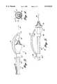
- FIG. 1illustrates an atherectomy device including a bias wire according to a first embodiment of the present invention
- FIG. 2illustrates how the bias wire laterally displaces an ablating burr in a patient's vessel
- FIG. 3illustrates an atherectomy device including a pair of bias wires according to a second embodiment of the present invention
- FIG. 4illustrates the orientation of the bias wires in the atherectomy device shown in FIG. 3;
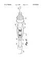
- FIG. 5illustrates an atherectomy device having a pair of bias wires that terminate proximally to an ablation burr according to a third embodiment of the present invention
- FIG. 6illustrates an atherectomy device including a mechanism for rotating a bias wire according to another aspect of the present invention.
- FIGS. 7 and 8illustrate alternative mechanisms for rotating the bias wires in an atherectomy device.
- the present inventionis an atherectomy device having one or more bias wires that cause an ablation burr to directionally ablate an occlusion in a patient's blood vessel.
- FIG. 1illustrates a first embodiment of an atherectomy device that is constructed according to the present invention.
- the atherectomy device 10includes a drive shaft 12 having an ablation burr 14 secured to its distal end.
- the ablation burr 14is completely or partially coated with an abrasive 16, typically diamond chips or dust, that grinds occluding matter in a patient's blood vessel into pieces that are sufficiently small such that they will not re-embolize downstream.
- the drive shaft 12is coupled to a source of rotational motion (not shown) such as an electric motor or turbine that spins the ablation burr at rates between 100,000 and 200,000 rpm.
- the drive shaft 12 and ablation burr 14include a central lumen that allows the drive shaft and burr to be threaded over a guide wire 18.
- the position of the guide wire 18can be adjusted by a physician in order to place the ablation burr 14 adjacent an occlusion within a patient's blood vessel.
- a catheter 20Surrounding the drive shaft 12 behind or proximal the ablation burr is a catheter 20.
- the catheter 20is lined with a low friction material such as TeflonTM.
- TeflonTMa low friction material
- the present inventionis an ablation device with the ability to directionally ablate an occlusion within a vessel such that a smaller burr can be used to create a larger lumen.
- the present inventionis an atherectomy device that includes a bias wire that extends generally parallel to and spaced apart from the longitudinal axis of the drive shaft 12 such that the distance between the bias wire and the outer diameter of the drive shaft 12 is greater than the maximum radius of the ablation burr 14.
- the bias wire 30includes a first end 32 that is slidably inserted into a lumen 34 formed at the distal end of the catheter 20 and adjacent the main lumen through which the drive shaft 12 is passed.
- the bias wire 30is looped around the drive shaft 12 at a position proximal to the ablation burr 14 and extends over the ablation burr 14.
- a second end 36 of the bias wireis looped around the guide wire 18 at a position that is ahead of or distal to the ablation burr 14.
- the atherectomy device 10may include a bearing 38 made of brass or other suitable material that is positioned between the distal end of the ablation burr 14 and the second end 36 of the bias wire 30. The bearing 38 prevents the abrasive surface 16 of the ablation burr from engaging the bias wire 30 during use.
- FIG. 2illustrates how the bias wire 30 operates to allow the atherectomy device to directionally ablate in a patient's blood vessel.
- a blood vessel 50is shown having an obstruction 52 on either side of the vessel wall that may totally or partially occlude the vessel.
- An initial lumen 54is cut through the obstruction 52 using an ablation device without the bias wire 30 shown above.
- the lumen 54may or may not be centrally located within the blood vessel. Once the initial lumen 54 has been cut, it is generally desirable to increase the size of the lumen in order to decrease the likelihood that the vessel will become re-occluded.
- the atherectomy device 10 having a bias wire 30is inserted into the vessel 50 and advanced until the bias wire 30 engages the obstruction 52.
- the bias wireforces the ablation burr 14 to be displaced laterally in the vessel thereby allowing the ablation burr 14 to engage more of the obstruction 52 on the side of the burr opposite the bias wire, thereby increasing the size of the lumen. Because the ablation burr is displaced by the bias wire in one direction, it is typically necessary to rotate the bias wire 30 and pass the ablation burr over the obstruction 52 in order to maximize the size of the lumen created.
- the first end 32 of the bias wire 30is retracted into the catheter lumen 34. Therefore, the flex of the bias wire behind or proximal to the ablation burr 14 is reduced and the bias wire 34 can be rotated by rotating the catheter 20.
- FIG. 3illustrates an ablation device 60 including a drive shaft 62, an ablation burr 64 disposed at the distal end of the drive shaft, and a guide wire 66 that extends through the center of the drive shaft and ablation burr.
- the drive shaft 62is positioned within a central lumen of a catheter 68 in the conventional fashion.
- the ablation device 60includes a pair of bias wires 72, 74 that extend over the ablation burr 64.
- Each bias wire 72, 74has a first end that is secured to a slip bearing 76 that is positioned over the drive shaft 62 and proximal to the ablation burr 64 and a second end that is secured to a slip bearing 78 that is positioned over the guide wire 66 and distal to the ablation burr 64.
- a bushing 80may be positioned between the slip bearing 78 and the distal end of the ablation burr 64 to prevent the ablation burr from engaging the bias wires during use.
- the bias wires 72 and 74are preferably secured to the slip bearings 76 and 78 at an angle between 20 and 60 degrees with respect to one another such that a triangle is formed between the bias wires 72, 74 and the opposite surface of the ablation burr 64 that is engaging the occluding material in the patient's vessel. With the two bias wires, the ablation burr 64 is held more securely in the patient's vessel and is less likely to slip into a previously ablated track.
- the atherectomy device 90includes a drive draft 92, an ablation burr 94 disposed at the distal end of the draft shaft, and a guide wire 96 extending through the draft shaft and the ablation burr.
- a slip bearing 98Positioned just proximal to the ablation burr 94 is a slip bearing 98 having a diameter that is a maximum where the slip bearing 98 abuts the ablation burr 94 and tapers towards the drive shaft 92 in the direction proximal to the ablation burr 94.
- a stop band 100is secured around the drive shaft 92 just proximal to the slip bearing 98 in order to limit the travel of the slip bearing 98 on the drive shaft 92.
- a second slip bearing 102is positioned over the drive shaft 92 proximal to the stop band 100.
- a pair of bias wires 104, 106each have one end secured to the slip bearing 102 and another end secured to the slip bearing 98.
- the bias wiresare gently curved with respect to the drive shaft 92 such that a portion of the guide wire has a radius from the drive shaft that is greater than the maximum radius of the ablation burr 94.
- the bias wires 104, 106are oriented at an angle between 20 and 60 degrees with respect to each other such that a triangle is formed between the bias wires and the surface of the ablation burr 94 that engages the obstruction in the vessel.
- a wire 108is secured to the slip bearing 102.
- the other end of the wire 108is positioned in a side lumen of a catheter surrounding the drive shaft in the same manner as the embodiments of the invention shown in FIGS. 1 and 3.
- the atherectomy device of the present inventionwill tend to be biased in a direction determined by the orientation of the bias wires in the vessel.
- a wireextends into a side lumen at the distal end of the catheter that surrounds the drive shaft. Therefore, by rotating the catheter with the wire in the side lumen, the bias wires can be re-oriented in the blood vessel and the ablation burr can ablate another path in the obstruction.
- FIGS. 6-8illustrate several different embodiments of the invention whereby the bias wires do not need to be coupled directly to the catheter that surrounds the drive shaft.
- an atherectomy device 110includes a drive shaft 112, an ablation burr 114 disposed at the distal end of the drive shaft, and a guide wire 116 that extends through the draft shaft and ablation burr.
- Surrounding the drive shaft 112is a conventional catheter 118.
- the atherectomy deviceincludes a slip bearing 120 that is positioned just proximal to the ablation burr 114.
- a second slip bearing 122is positioned proximal to the slip bearing 120.
- a pair of stop rings 124, 126are secured to the drive shaft between the slip bearings 120 and 122.
- a pair of bias wires 130, 132are secured to the slip bearings 120 and 122.
- the bias wiresare oriented at an angle between 20 and 60 degrees with respect to one another in the same manner as the bias wires shown in FIGS. 3 and 4. Again, the bias wires have a maximum radius from the drive shaft that is greater than the maximum radius of the ablation burr.
- the distal end of the catheter 118is configured to engage the proximal end of the slip bearing 122 such that when the drive shaft is retracted into the catheter, the bias wires can be rotated by rotating the catheter 118.
- the distal end of the catheter 118includes a cap 134 having a number of vertices into which a correspondingly shaped nut 126 on the proximal end of the slip bearing 122 can be inserted.
- the cap 134is formed as a six-sided socket that mates with a correspondingly shaped six-sided nut on the slip bearing 122.
- a surgeonablates a path with the bias wires in a particular direction and then retracts the drive shaft until the bias wires are held in place by the cap 134 at the distal end of the catheter.
- the catheteris then rotated and the ablation burr is advanced to ablate a new path in the patients vessel. This pattern typically continues until the bias wires have been rotated substantially around the circumference of the vessel.
- FIGS. 7 and 8show alternative embodiments for engaging the bias wires in the distal end of the catheter.
- FIG. 7illustrates an atherectomy device 140 including a drive shaft 112, an ablation burr 114, a guide wire 116, and a slip bearing 120 that are identical to those components shown in FIG. 6.
- a pair of bias wires 130, 132are secured at the one end to the slip bearing 120 and at the other end to a slip bearing 142 that is proximal to the slip bearing 120.
- a pair of stop rings 144, 146are secured to the drive shaft between the slip bearings 120 and 142.
- the catheter 148 that surrounds the drive shaft 112has a lumen with a sufficiently wide opening at its distal end such that a portion of the slip bearing 142 and the bias wires 130, 132 can be drawn into the catheter.
- the slip bearing 142 and bias wires 120, 122are held in place by a friction fit that allows the bias wires to be rotated in the vessel by rotating the catheter 148.
- the proximal end of the slip bearing 142may be tapered to cooperate with the size/shape of the lumen within the catheter 148.
- a lumen of a catheter 152 that surrounds the drive wire 112includes one or more notches 154 disposed at its distal end.
- the notchesare shaped to receive the bias wires 130, 132 as the drive shaft is pulled proximally into the catheter.
- the bias wirescan be rotated by rotating the catheter.
- the drive shaftis then moved forward and the bias wires are forced from the notch 154 at the distal end of the catheter and a new path can be ablated.
- the present inventionis an ablation device that allows a physician to ablate a larger lumen in a patient's vessel without the use of a larger ablation burr.
- the ablation burrwill be directed laterally in the patient's vessel thereby allowing a larger lumen to be cut in an obstruction.
Landscapes
- Health & Medical Sciences (AREA)
- Surgery (AREA)
- Life Sciences & Earth Sciences (AREA)
- Biomedical Technology (AREA)
- Nuclear Medicine, Radiotherapy & Molecular Imaging (AREA)
- Engineering & Computer Science (AREA)
- Vascular Medicine (AREA)
- Heart & Thoracic Surgery (AREA)
- Medical Informatics (AREA)
- Molecular Biology (AREA)
- Animal Behavior & Ethology (AREA)
- General Health & Medical Sciences (AREA)
- Public Health (AREA)
- Veterinary Medicine (AREA)
- Surgical Instruments (AREA)
Abstract
Description
Claims (8)
Priority Applications (3)
| Application Number | Priority Date | Filing Date | Title |
|---|---|---|---|
| US09/243,013US6113615A (en) | 1999-02-03 | 1999-02-03 | Atherectomy burr including a bias wire |
| PCT/US2000/002722WO2000045717A1 (en) | 1999-02-03 | 2000-02-02 | Atherectomy burr including a bias wire |
| US09/589,993US6299623B1 (en) | 1999-02-03 | 2000-06-08 | Atherectomy burr including a bias wire |
Applications Claiming Priority (1)
| Application Number | Priority Date | Filing Date | Title |
|---|---|---|---|
| US09/243,013US6113615A (en) | 1999-02-03 | 1999-02-03 | Atherectomy burr including a bias wire |
Related Child Applications (1)
| Application Number | Title | Priority Date | Filing Date |
|---|---|---|---|
| US09/589,993ContinuationUS6299623B1 (en) | 1999-02-03 | 2000-06-08 | Atherectomy burr including a bias wire |
Publications (1)
| Publication Number | Publication Date |
|---|---|
| US6113615Atrue US6113615A (en) | 2000-09-05 |
Family
ID=22917009
Family Applications (2)
| Application Number | Title | Priority Date | Filing Date |
|---|---|---|---|
| US09/243,013Expired - Fee RelatedUS6113615A (en) | 1999-02-03 | 1999-02-03 | Atherectomy burr including a bias wire |
| US09/589,993Expired - LifetimeUS6299623B1 (en) | 1999-02-03 | 2000-06-08 | Atherectomy burr including a bias wire |
Family Applications After (1)
| Application Number | Title | Priority Date | Filing Date |
|---|---|---|---|
| US09/589,993Expired - LifetimeUS6299623B1 (en) | 1999-02-03 | 2000-06-08 | Atherectomy burr including a bias wire |
Country Status (2)
| Country | Link |
|---|---|
| US (2) | US6113615A (en) |
| WO (1) | WO2000045717A1 (en) |
Cited By (27)
| Publication number | Priority date | Publication date | Assignee | Title |
|---|---|---|---|---|
| US6270509B1 (en)* | 1997-03-06 | 2001-08-07 | Scimed Life Systems, Inc. | Cancave atherectomy burr with smooth rims |
| WO2002083010A1 (en) | 2001-04-12 | 2002-10-24 | Pearl Technology Holdings, Llc | Ultrasound plaque emulsion device |
| US20030120296A1 (en)* | 2001-10-19 | 2003-06-26 | Leonid Shturman | Control system for rotational angioplasty device |
| US6620179B2 (en)* | 1999-08-10 | 2003-09-16 | Neurovasx, Inc. | Clot disrupting wire/catheter assembly |
| US20040133209A1 (en)* | 2002-09-19 | 2004-07-08 | Chappuis James L. | Medical bur |
| US20070083220A1 (en)* | 2004-06-09 | 2007-04-12 | Ovalum Ltd. | Blood vessel occlusion auger |
| US20090187179A1 (en)* | 2006-02-22 | 2009-07-23 | Racz N Sandor | Ablation Instruments and Related Methods |
| US20090230167A1 (en)* | 2008-03-17 | 2009-09-17 | Medtronic Vascular, Inc. | Endostapler Biasing Mechanism |
| US20100121361A1 (en)* | 2008-06-05 | 2010-05-13 | Cardiovascular Systems, Inc. | Directional rotational atherectomy device with offset spinning abrasive element |
| US20140018833A1 (en)* | 2012-07-13 | 2014-01-16 | Boston Scientific Scimed, Inc. | Wire-guided recanalization system |
| US20140316450A1 (en)* | 2013-03-14 | 2014-10-23 | Cardiovascular Systems, Inc | Devices, systems and methods for an oscillating crown drive for rotational atherectomy |
| US20170020554A1 (en)* | 2015-02-28 | 2017-01-26 | Transmed7, Llc | Devices and methods for percutaneous transluminal angioplasty and atherectomy intervention procedures |
| US10271869B2 (en) | 2014-03-01 | 2019-04-30 | Rex Medical, L.P. | Atherectomy device |
| US10307175B2 (en) | 2016-03-26 | 2019-06-04 | Rex Medical, L.P | Atherectomy device |
| US10433868B2 (en) | 2014-12-27 | 2019-10-08 | Rex Medical, L.P. | Artherectomy device |
| US10463389B2 (en) | 2014-12-27 | 2019-11-05 | Rex Medical, L.P. | Atherectomy device |
| US10869689B2 (en) | 2017-05-03 | 2020-12-22 | Medtronic Vascular, Inc. | Tissue-removing catheter |
| US11253292B2 (en) | 2015-09-13 | 2022-02-22 | Rex Medical, L.P. | Atherectomy device |
| CN114269267A (en)* | 2019-06-18 | 2022-04-01 | 波士顿科学国际有限公司 | Atherectomy system with guidewire detection |
| US11304723B1 (en)* | 2020-12-17 | 2022-04-19 | Avantec Vascular Corporation | Atherectomy devices that are self-driving with controlled deflection |
| US11419628B2 (en) | 2018-09-10 | 2022-08-23 | Medtronic Vascular, Inc. | Tissue-removing catheter with guidewire detection sensor |
| US11690645B2 (en) | 2017-05-03 | 2023-07-04 | Medtronic Vascular, Inc. | Tissue-removing catheter |
| US11819236B2 (en) | 2019-05-17 | 2023-11-21 | Medtronic Vascular, Inc. | Tissue-removing catheter |
| US12171457B2 (en) | 2020-10-30 | 2024-12-24 | Boston Scientific Scimed, Inc. | Atherectomy burrs with blood flow enhancements |
| US12220140B1 (en) | 2023-08-16 | 2025-02-11 | Avantec Vascular Corporation | Thrombectomy devices with lateral and vertical bias |
| US12290279B2 (en) | 2021-06-07 | 2025-05-06 | Avantec Vascular Corporation | Hybrid atherectomy devices |
| US12414785B1 (en) | 2025-03-17 | 2025-09-16 | Avantec Vascular Corporation | Cutters with pulsating vacuum control |
Families Citing this family (122)
| Publication number | Priority date | Publication date | Assignee | Title |
|---|---|---|---|---|
| US6090118A (en) | 1998-07-23 | 2000-07-18 | Mcguckin, Jr.; James F. | Rotational thrombectomy apparatus and method with standing wave |
| WO2001028618A2 (en) | 1999-10-22 | 2001-04-26 | Boston Scientific Corporation | Double balloon thrombectomy catheter |
| US7037316B2 (en) | 1997-07-24 | 2006-05-02 | Mcguckin Jr James F | Rotational thrombectomy device |
| US8328829B2 (en) | 1999-08-19 | 2012-12-11 | Covidien Lp | High capacity debulking catheter with razor edge cutting window |
| US7887556B2 (en) | 2000-12-20 | 2011-02-15 | Fox Hollow Technologies, Inc. | Debulking catheters and methods |
| US6299622B1 (en) | 1999-08-19 | 2001-10-09 | Fox Hollow Technologies, Inc. | Atherectomy catheter with aligned imager |
| US7708749B2 (en) | 2000-12-20 | 2010-05-04 | Fox Hollow Technologies, Inc. | Debulking catheters and methods |
| US7713279B2 (en) | 2000-12-20 | 2010-05-11 | Fox Hollow Technologies, Inc. | Method and devices for cutting tissue |
| US8414543B2 (en) | 1999-10-22 | 2013-04-09 | Rex Medical, L.P. | Rotational thrombectomy wire with blocking device |
| DE10049865B8 (en)* | 2000-10-09 | 2008-10-30 | Universitätsklinikum Freiburg | Device for removing an aortic valve on the human heart by means of a minimally invasive surgical procedure |
| JP4080874B2 (en) | 2000-12-20 | 2008-04-23 | フォックス ハロウ テクノロジーズ,インコーポレイティド | Bulking catheter |
| US6569177B1 (en) | 2001-01-19 | 2003-05-27 | Scimed Life Systems, Inc. | Ablation atherectomy burr |
| US6800083B2 (en) | 2001-04-09 | 2004-10-05 | Scimed Life Systems, Inc. | Compressible atherectomy burr |
| US6926725B2 (en) | 2002-04-04 | 2005-08-09 | Rex Medical, L.P. | Thrombectomy device with multi-layered rotational wire |
| US7179269B2 (en) | 2002-05-20 | 2007-02-20 | Scimed Life Systems, Inc. | Apparatus and system for removing an obstruction from a lumen |
| US8246640B2 (en) | 2003-04-22 | 2012-08-21 | Tyco Healthcare Group Lp | Methods and devices for cutting tissue at a vascular location |
| DE202004021953U1 (en) | 2003-09-12 | 2013-06-19 | Vessix Vascular, Inc. | Selectable eccentric remodeling and / or ablation of atherosclerotic material |
| US8396548B2 (en) | 2008-11-14 | 2013-03-12 | Vessix Vascular, Inc. | Selective drug delivery in a lumen |
| US9713730B2 (en) | 2004-09-10 | 2017-07-25 | Boston Scientific Scimed, Inc. | Apparatus and method for treatment of in-stent restenosis |
| EP2438877B1 (en) | 2005-03-28 | 2016-02-17 | Vessix Vascular, Inc. | Intraluminal electrical tissue characterization and tuned RF energy for selective treatment of atheroma and other target tissues |
| US7853388B2 (en)* | 2006-02-23 | 2010-12-14 | Siemens Industry, Inc. | Devices, systems, and methods for controlling a braking system |
| US8019435B2 (en) | 2006-05-02 | 2011-09-13 | Boston Scientific Scimed, Inc. | Control of arterial smooth muscle tone |
| US20070276419A1 (en) | 2006-05-26 | 2007-11-29 | Fox Hollow Technologies, Inc. | Methods and devices for rotating an active element and an energy emitter on a catheter |
| EP2455036B1 (en) | 2006-10-18 | 2015-07-15 | Vessix Vascular, Inc. | Tuned RF energy and electrical tissue characterization for selective treatment of target tissues |
| EP2076198A4 (en) | 2006-10-18 | 2009-12-09 | Minnow Medical Inc | Inducing desirable temperature effects on body tissue |
| JP5559539B2 (en) | 2006-10-18 | 2014-07-23 | べシックス・バスキュラー・インコーポレイテッド | System that induces desirable temperature effects on body tissue |
| US8496653B2 (en) | 2007-04-23 | 2013-07-30 | Boston Scientific Scimed, Inc. | Thrombus removal |
| US8784440B2 (en) | 2008-02-25 | 2014-07-22 | Covidien Lp | Methods and devices for cutting tissue |
| US8414604B2 (en) | 2008-10-13 | 2013-04-09 | Covidien Lp | Devices and methods for manipulating a catheter shaft |
| EP2355737B1 (en) | 2008-11-17 | 2021-08-11 | Boston Scientific Scimed, Inc. | Selective accumulation of energy without knowledge of tissue topography |
| CN102625673B (en) | 2009-04-29 | 2014-12-24 | 泰科保健集团有限合伙公司 | Methods and devices for cutting and abrading tissue |
| US8551096B2 (en) | 2009-05-13 | 2013-10-08 | Boston Scientific Scimed, Inc. | Directional delivery of energy and bioactives |
| WO2010132748A1 (en) | 2009-05-14 | 2010-11-18 | Fox Hollow Technologies, Inc. | Easily cleaned atherectomy catheters and methods of use |
| WO2011068932A1 (en) | 2009-12-02 | 2011-06-09 | Fox Hollow Technologies, Inc. | Methods and devices for cutting tissue |
| CN102695463B (en) | 2009-12-11 | 2015-01-14 | 泰科保健集团有限合伙公司 | Material removal device having improved material capture efficiency and methods of use |
| WO2011126580A2 (en) | 2010-04-09 | 2011-10-13 | Minnow Medical, Inc. | Power generating and control apparatus for the treatment of tissue |
| US9192790B2 (en) | 2010-04-14 | 2015-11-24 | Boston Scientific Scimed, Inc. | Focused ultrasonic renal denervation |
| US8473067B2 (en) | 2010-06-11 | 2013-06-25 | Boston Scientific Scimed, Inc. | Renal denervation and stimulation employing wireless vascular energy transfer arrangement |
| RU2538174C2 (en) | 2010-06-14 | 2015-01-10 | Ковидиен Лп | Device for material removal |
| US9084609B2 (en) | 2010-07-30 | 2015-07-21 | Boston Scientific Scime, Inc. | Spiral balloon catheter for renal nerve ablation |
| US9155589B2 (en) | 2010-07-30 | 2015-10-13 | Boston Scientific Scimed, Inc. | Sequential activation RF electrode set for renal nerve ablation |
| US9358365B2 (en) | 2010-07-30 | 2016-06-07 | Boston Scientific Scimed, Inc. | Precision electrode movement control for renal nerve ablation |
| US9408661B2 (en) | 2010-07-30 | 2016-08-09 | Patrick A. Haverkost | RF electrodes on multiple flexible wires for renal nerve ablation |
| US9463062B2 (en) | 2010-07-30 | 2016-10-11 | Boston Scientific Scimed, Inc. | Cooled conductive balloon RF catheter for renal nerve ablation |
| US9084610B2 (en) | 2010-10-21 | 2015-07-21 | Medtronic Ardian Luxembourg S.A.R.L. | Catheter apparatuses, systems, and methods for renal neuromodulation |
| US8974451B2 (en) | 2010-10-25 | 2015-03-10 | Boston Scientific Scimed, Inc. | Renal nerve ablation using conductive fluid jet and RF energy |
| US9220558B2 (en) | 2010-10-27 | 2015-12-29 | Boston Scientific Scimed, Inc. | RF renal denervation catheter with multiple independent electrodes |
| CA2815186C (en) | 2010-10-28 | 2015-12-29 | Covidien Lp | Material removal device and method of use |
| KR20150020240A (en) | 2010-11-11 | 2015-02-25 | 코비디엔 엘피 | Flexible debulking catheters with imaging and methods of use and manufacture |
| US9028485B2 (en) | 2010-11-15 | 2015-05-12 | Boston Scientific Scimed, Inc. | Self-expanding cooling electrode for renal nerve ablation |
| US9089350B2 (en) | 2010-11-16 | 2015-07-28 | Boston Scientific Scimed, Inc. | Renal denervation catheter with RF electrode and integral contrast dye injection arrangement |
| US9668811B2 (en) | 2010-11-16 | 2017-06-06 | Boston Scientific Scimed, Inc. | Minimally invasive access for renal nerve ablation |
| US9326751B2 (en) | 2010-11-17 | 2016-05-03 | Boston Scientific Scimed, Inc. | Catheter guidance of external energy for renal denervation |
| US9060761B2 (en) | 2010-11-18 | 2015-06-23 | Boston Scientific Scime, Inc. | Catheter-focused magnetic field induced renal nerve ablation |
| US9023034B2 (en) | 2010-11-22 | 2015-05-05 | Boston Scientific Scimed, Inc. | Renal ablation electrode with force-activatable conduction apparatus |
| US9192435B2 (en) | 2010-11-22 | 2015-11-24 | Boston Scientific Scimed, Inc. | Renal denervation catheter with cooled RF electrode |
| US20120157993A1 (en) | 2010-12-15 | 2012-06-21 | Jenson Mark L | Bipolar Off-Wall Electrode Device for Renal Nerve Ablation |
| US9220561B2 (en) | 2011-01-19 | 2015-12-29 | Boston Scientific Scimed, Inc. | Guide-compatible large-electrode catheter for renal nerve ablation with reduced arterial injury |
| US9055951B2 (en) | 2011-05-23 | 2015-06-16 | Covidien Lp | Endovascular tissue removal device |
| CN103813745B (en) | 2011-07-20 | 2016-06-29 | 波士顿科学西美德公司 | In order to visualize, be directed at and to melt transcutaneous device and the method for nerve |
| EP2734264B1 (en) | 2011-07-22 | 2018-11-21 | Boston Scientific Scimed, Inc. | Nerve modulation system with a nerve modulation element positionable in a helical guide |
| EP2750862B1 (en) | 2011-09-01 | 2016-07-06 | Covidien LP | Catheter with helical drive shaft and methods of manufacture |
| WO2013055826A1 (en) | 2011-10-10 | 2013-04-18 | Boston Scientific Scimed, Inc. | Medical devices including ablation electrodes |
| EP2765940B1 (en) | 2011-10-11 | 2015-08-26 | Boston Scientific Scimed, Inc. | Off-wall electrode device for nerve modulation |
| US9420955B2 (en) | 2011-10-11 | 2016-08-23 | Boston Scientific Scimed, Inc. | Intravascular temperature monitoring system and method |
| US9364284B2 (en) | 2011-10-12 | 2016-06-14 | Boston Scientific Scimed, Inc. | Method of making an off-wall spacer cage |
| US9162046B2 (en) | 2011-10-18 | 2015-10-20 | Boston Scientific Scimed, Inc. | Deflectable medical devices |
| EP2768568B1 (en) | 2011-10-18 | 2020-05-06 | Boston Scientific Scimed, Inc. | Integrated crossing balloon catheter |
| US8951251B2 (en) | 2011-11-08 | 2015-02-10 | Boston Scientific Scimed, Inc. | Ostial renal nerve ablation |
| WO2013074813A1 (en) | 2011-11-15 | 2013-05-23 | Boston Scientific Scimed, Inc. | Device and methods for renal nerve modulation monitoring |
| US9119632B2 (en) | 2011-11-21 | 2015-09-01 | Boston Scientific Scimed, Inc. | Deflectable renal nerve ablation catheter |
| US9265969B2 (en) | 2011-12-21 | 2016-02-23 | Cardiac Pacemakers, Inc. | Methods for modulating cell function |
| US9028472B2 (en) | 2011-12-23 | 2015-05-12 | Vessix Vascular, Inc. | Methods and apparatuses for remodeling tissue of or adjacent to a body passage |
| EP2797534A1 (en) | 2011-12-28 | 2014-11-05 | Boston Scientific Scimed, Inc. | Device and methods for nerve modulation using a novel ablation catheter with polymeric ablative elements |
| US9050106B2 (en) | 2011-12-29 | 2015-06-09 | Boston Scientific Scimed, Inc. | Off-wall electrode device and methods for nerve modulation |
| US9056191B2 (en) | 2012-04-11 | 2015-06-16 | Covidien Lp | Apparatus and method for removing occlusive tissue |
| US10660703B2 (en) | 2012-05-08 | 2020-05-26 | Boston Scientific Scimed, Inc. | Renal nerve modulation devices |
| US9629646B2 (en) | 2012-07-11 | 2017-04-25 | Jens Kather | Curved burr surgical instrument |
| US10321946B2 (en) | 2012-08-24 | 2019-06-18 | Boston Scientific Scimed, Inc. | Renal nerve modulation devices with weeping RF ablation balloons |
| US9532844B2 (en) | 2012-09-13 | 2017-01-03 | Covidien Lp | Cleaning device for medical instrument and method of use |
| CN104780859B (en) | 2012-09-17 | 2017-07-25 | 波士顿科学西美德公司 | Self-positioning electrode systems and methods for renal neuromodulation |
| US10549127B2 (en) | 2012-09-21 | 2020-02-04 | Boston Scientific Scimed, Inc. | Self-cooling ultrasound ablation catheter |
| US10398464B2 (en) | 2012-09-21 | 2019-09-03 | Boston Scientific Scimed, Inc. | System for nerve modulation and innocuous thermal gradient nerve block |
| CN104869930B (en) | 2012-10-10 | 2020-12-25 | 波士顿科学国际有限公司 | Renal neuromodulation apparatus and methods |
| US9044575B2 (en) | 2012-10-22 | 2015-06-02 | Medtronic Adrian Luxembourg S.a.r.l. | Catheters with enhanced flexibility and associated devices, systems, and methods |
| US9943329B2 (en) | 2012-11-08 | 2018-04-17 | Covidien Lp | Tissue-removing catheter with rotatable cutter |
| WO2014143571A1 (en) | 2013-03-11 | 2014-09-18 | Boston Scientific Scimed, Inc. | Medical devices for modulating nerves |
| WO2014163987A1 (en) | 2013-03-11 | 2014-10-09 | Boston Scientific Scimed, Inc. | Medical devices for modulating nerves |
| US9808311B2 (en) | 2013-03-13 | 2017-11-07 | Boston Scientific Scimed, Inc. | Deflectable medical devices |
| EP2967734B1 (en) | 2013-03-15 | 2019-05-15 | Boston Scientific Scimed, Inc. | Methods and apparatuses for remodeling tissue of or adjacent to a body passage |
| US10265122B2 (en) | 2013-03-15 | 2019-04-23 | Boston Scientific Scimed, Inc. | Nerve ablation devices and related methods of use |
| CN105228546B (en) | 2013-03-15 | 2017-11-14 | 波士顿科学国际有限公司 | Medical devices and methods for treating hypertension utilizing impedance compensation |
| EP2996754B1 (en) | 2013-05-18 | 2023-04-26 | Medtronic Ardian Luxembourg S.à.r.l. | Neuromodulation catheters with shafts for enhanced flexibility and control and associated devices and systems |
| CN105473091B (en) | 2013-06-21 | 2020-01-21 | 波士顿科学国际有限公司 | Renal denervation balloon catheter with co-movable electrode supports |
| CN105473092B (en) | 2013-06-21 | 2019-05-17 | 波士顿科学国际有限公司 | The medical instrument for renal nerve ablation with rotatable shaft |
| US9707036B2 (en) | 2013-06-25 | 2017-07-18 | Boston Scientific Scimed, Inc. | Devices and methods for nerve modulation using localized indifferent electrodes |
| CN105358084B (en) | 2013-07-01 | 2018-11-09 | 波士顿科学国际有限公司 | Medical instrument for renal nerve ablation |
| CN105377169B (en) | 2013-07-11 | 2019-04-19 | 波士顿科学国际有限公司 | Devices and methods for neuromodulation |
| US10413357B2 (en) | 2013-07-11 | 2019-09-17 | Boston Scientific Scimed, Inc. | Medical device with stretchable electrode assemblies |
| US9925001B2 (en) | 2013-07-19 | 2018-03-27 | Boston Scientific Scimed, Inc. | Spiral bipolar electrode renal denervation balloon |
| US10695124B2 (en) | 2013-07-22 | 2020-06-30 | Boston Scientific Scimed, Inc. | Renal nerve ablation catheter having twist balloon |
| US10342609B2 (en) | 2013-07-22 | 2019-07-09 | Boston Scientific Scimed, Inc. | Medical devices for renal nerve ablation |
| CN105473093B (en) | 2013-08-22 | 2019-02-05 | 波士顿科学国际有限公司 | Flexible circuit with improved adhesion to renal neuromodulation balloon |
| US9895194B2 (en) | 2013-09-04 | 2018-02-20 | Boston Scientific Scimed, Inc. | Radio frequency (RF) balloon catheter having flushing and cooling capability |
| EP3043733A1 (en) | 2013-09-13 | 2016-07-20 | Boston Scientific Scimed, Inc. | Ablation balloon with vapor deposited cover layer |
| US11246654B2 (en) | 2013-10-14 | 2022-02-15 | Boston Scientific Scimed, Inc. | Flexible renal nerve ablation devices and related methods of use and manufacture |
| EP3057488B1 (en) | 2013-10-14 | 2018-05-16 | Boston Scientific Scimed, Inc. | High resolution cardiac mapping electrode array catheter |
| US9962223B2 (en) | 2013-10-15 | 2018-05-08 | Boston Scientific Scimed, Inc. | Medical device balloon |
| US9770606B2 (en) | 2013-10-15 | 2017-09-26 | Boston Scientific Scimed, Inc. | Ultrasound ablation catheter with cooling infusion and centering basket |
| EP3057521B1 (en) | 2013-10-18 | 2020-03-25 | Boston Scientific Scimed, Inc. | Balloon catheters with flexible conducting wires |
| CN105658163B (en) | 2013-10-25 | 2020-08-18 | 波士顿科学国际有限公司 | Embedded thermocouple in denervation flexible circuit |
| EP3091922B1 (en) | 2014-01-06 | 2018-10-17 | Boston Scientific Scimed, Inc. | Tear resistant flex circuit assembly |
| EP4253024B1 (en) | 2014-01-27 | 2025-02-26 | Medtronic Ireland Manufacturing Unlimited Company | Neuromodulation catheters having jacketed neuromodulation elements and related devices |
| US11000679B2 (en) | 2014-02-04 | 2021-05-11 | Boston Scientific Scimed, Inc. | Balloon protection and rewrapping devices and related methods of use |
| CN106572881B (en) | 2014-02-04 | 2019-07-26 | 波士顿科学国际有限公司 | Alternative placement of thermal sensors on bipolar electrodes |
| CN106232043B (en) | 2014-04-24 | 2019-07-23 | 美敦力阿迪安卢森堡有限公司 | Nerve modulation conduit and relevant system and method with braiding axle |
| FR3021860A1 (en)* | 2014-06-05 | 2015-12-11 | Bernard Pain | TRANSCATHETER DEVICE FOR ABLATION OF CALCIFIED FABRICS AT THE LEVELS OF AN AORTIC VALVE |
| WO2015200702A1 (en) | 2014-06-27 | 2015-12-30 | Covidien Lp | Cleaning device for catheter and catheter including the same |
| US10314667B2 (en) | 2015-03-25 | 2019-06-11 | Covidien Lp | Cleaning device for cleaning medical instrument |
| US10292721B2 (en) | 2015-07-20 | 2019-05-21 | Covidien Lp | Tissue-removing catheter including movable distal tip |
| US10314664B2 (en) | 2015-10-07 | 2019-06-11 | Covidien Lp | Tissue-removing catheter and tissue-removing element with depth stop |
| CN118697424A (en) | 2018-11-16 | 2024-09-27 | 美敦力瓦斯科尔勒公司 | Tissue Removal Catheter |
Citations (32)
| Publication number | Priority date | Publication date | Assignee | Title |
|---|---|---|---|---|
| US33569A (en)* | 1861-10-29 | Improvement in braiding-machines | ||
| EP0117519A1 (en)* | 1983-02-23 | 1984-09-05 | Johannes Dipl.-Ing. Theermann | Catheter |
| US4669469A (en)* | 1986-02-28 | 1987-06-02 | Devices For Vascular Intervention | Single lumen atherectomy catheter device |
| US4747405A (en)* | 1984-03-01 | 1988-05-31 | Vaser, Inc. | Angioplasty catheter |
| US4909781A (en)* | 1988-04-08 | 1990-03-20 | Husted Royce Hill | Catheter with flexible cutter |
| US4950277A (en)* | 1989-01-23 | 1990-08-21 | Interventional Technologies, Inc. | Atherectomy cutting device with eccentric wire and method |
| US4979951A (en)* | 1984-05-30 | 1990-12-25 | Simpson John B | Atherectomy device and method |
| US5000185A (en)* | 1986-02-28 | 1991-03-19 | Cardiovascular Imaging Systems, Inc. | Method for intravascular two-dimensional ultrasonography and recanalization |
| USRE33569E (en) | 1986-02-28 | 1991-04-09 | Devices For Vascular Intervention, Inc. | Single lumen atherectomy catheter device |
| US5071425A (en)* | 1988-09-12 | 1991-12-10 | Devices For Vascular Intervention, Inc. | Atherectomy catheter and method of forming the same |
| US5100424A (en)* | 1990-05-21 | 1992-03-31 | Cardiovascular Imaging Systems, Inc. | Intravascular catheter having combined imaging abrasion head |
| EP0485133A1 (en)* | 1990-11-08 | 1992-05-13 | Possis Medical, Inc. | Asymmetric water jet atherectomy |
| WO1992007500A2 (en)* | 1990-10-25 | 1992-05-14 | Devices For Vascular Intervention, Inc. | Atherectomy catheter having axially-disposed cutting edge |
| US5226909A (en)* | 1989-09-12 | 1993-07-13 | Devices For Vascular Intervention, Inc. | Atherectomy device having helical blade and blade guide |
| US5250059A (en)* | 1992-01-22 | 1993-10-05 | Devices For Vascular Intervention, Inc. | Atherectomy catheter having flexible nose cone |
| US5269793A (en)* | 1989-07-20 | 1993-12-14 | Devices For Vascular Intervention, Inc. | Guide wire systems for intravascular catheters |
| US5312427A (en)* | 1992-10-16 | 1994-05-17 | Shturman Cardiology Systems, Inc. | Device and method for directional rotational atherectomy |
| US5360432A (en)* | 1992-10-16 | 1994-11-01 | Shturman Cardiology Systems, Inc. | Abrasive drive shaft device for directional rotational atherectomy |
| US5370651A (en)* | 1989-02-17 | 1994-12-06 | Summers; David P. | Distal atherectomy catheter |
| WO1995001753A1 (en)* | 1993-07-07 | 1995-01-19 | Devices For Vascular Intervention, Inc. | Flexible housing for intracorporeal use |
| US5431673A (en)* | 1989-02-17 | 1995-07-11 | American Biomed, Inc. | Distal atherectomy catheter |
| EP0669106A2 (en)* | 1984-05-30 | 1995-08-30 | Devices For Vascular Intervention Inc. | Atherectomy device |
| EP0359447B1 (en)* | 1988-09-12 | 1995-12-13 | Devices For Vascular Intervention, Inc. | Improved atherectomy catheter |
| RU2057488C1 (en)* | 1992-12-07 | 1996-04-10 | Научно-внедренческая производственная фирма "СМЕТ-2" | Papillotome device |
| RU2057489C1 (en)* | 1993-02-05 | 1996-04-10 | Научно-внедренческая производственная фирма "СМЕТ-2" | Device for dissecting narrow parts of tubular organs |
| US5527325A (en)* | 1993-07-09 | 1996-06-18 | Device For Vascular Intervention, Inc. | Atherectomy catheter and method |
| WO1996022737A1 (en)* | 1995-01-23 | 1996-08-01 | Houser Russell A | Atherectomy catheter and rf cutting method |
| US5569976A (en)* | 1995-06-14 | 1996-10-29 | Gavrilov; Nikolai V. | Ion emmiter based on cold cathode discharge |
| US5653696A (en)* | 1984-05-14 | 1997-08-05 | Surgical Systems & Instruments, Inc. | Stent unclogging method |
| US5836957A (en)* | 1994-12-22 | 1998-11-17 | Devices For Vascular Intervention, Inc. | Large volume atherectomy device |
| WO1999030624A1 (en)* | 1997-12-17 | 1999-06-24 | Fox Hollow Technologies | Apparatus and methods for removing occluding material from body lumens |
| US5938670A (en)* | 1992-10-07 | 1999-08-17 | Scimed Life Systems, Inc. | Ablation devices and methods of use |
Family Cites Families (3)
| Publication number | Priority date | Publication date | Assignee | Title |
|---|---|---|---|---|
| CA1293663C (en)* | 1986-01-06 | 1991-12-31 | David Christopher Auth | Transluminal microdissection device |
| US5116352A (en)* | 1989-10-06 | 1992-05-26 | Angiomed Ag | Apparatus for removing deposits from vessels |
| CA2273149A1 (en)* | 1996-12-02 | 1998-06-11 | Angiotrax, Inc. | Apparatus and methods for percutaneously performing surgery |
- 1999
- 1999-02-03USUS09/243,013patent/US6113615A/ennot_activeExpired - Fee Related
- 2000
- 2000-02-02WOPCT/US2000/002722patent/WO2000045717A1/enactiveApplication Filing
- 2000-06-08USUS09/589,993patent/US6299623B1/ennot_activeExpired - Lifetime
Patent Citations (37)
| Publication number | Priority date | Publication date | Assignee | Title |
|---|---|---|---|---|
| US33569A (en)* | 1861-10-29 | Improvement in braiding-machines | ||
| EP0117519A1 (en)* | 1983-02-23 | 1984-09-05 | Johannes Dipl.-Ing. Theermann | Catheter |
| US4747405A (en)* | 1984-03-01 | 1988-05-31 | Vaser, Inc. | Angioplasty catheter |
| US5653696A (en)* | 1984-05-14 | 1997-08-05 | Surgical Systems & Instruments, Inc. | Stent unclogging method |
| US4979951A (en)* | 1984-05-30 | 1990-12-25 | Simpson John B | Atherectomy device and method |
| EP0669106A2 (en)* | 1984-05-30 | 1995-08-30 | Devices For Vascular Intervention Inc. | Atherectomy device |
| EP0352872B1 (en)* | 1984-05-30 | 1996-04-24 | Devices For Vascular Intervention Inc. | Atherectomy device |
| EP0238217B1 (en)* | 1986-02-28 | 1993-08-04 | Devices For Vascular Intervention, Inc. | Atherectomy catheter device |
| USRE33569E (en) | 1986-02-28 | 1991-04-09 | Devices For Vascular Intervention, Inc. | Single lumen atherectomy catheter device |
| US5000185A (en)* | 1986-02-28 | 1991-03-19 | Cardiovascular Imaging Systems, Inc. | Method for intravascular two-dimensional ultrasonography and recanalization |
| US4669469A (en)* | 1986-02-28 | 1987-06-02 | Devices For Vascular Intervention | Single lumen atherectomy catheter device |
| US4909781A (en)* | 1988-04-08 | 1990-03-20 | Husted Royce Hill | Catheter with flexible cutter |
| US5071425A (en)* | 1988-09-12 | 1991-12-10 | Devices For Vascular Intervention, Inc. | Atherectomy catheter and method of forming the same |
| EP0359447B1 (en)* | 1988-09-12 | 1995-12-13 | Devices For Vascular Intervention, Inc. | Improved atherectomy catheter |
| US4950277A (en)* | 1989-01-23 | 1990-08-21 | Interventional Technologies, Inc. | Atherectomy cutting device with eccentric wire and method |
| EP0379786B1 (en)* | 1989-01-23 | 1995-03-29 | Interventional Technologies Inc | Atherectomy cutting device with eccentric wire |
| US5370651A (en)* | 1989-02-17 | 1994-12-06 | Summers; David P. | Distal atherectomy catheter |
| US5431673A (en)* | 1989-02-17 | 1995-07-11 | American Biomed, Inc. | Distal atherectomy catheter |
| US5269793A (en)* | 1989-07-20 | 1993-12-14 | Devices For Vascular Intervention, Inc. | Guide wire systems for intravascular catheters |
| US5226909A (en)* | 1989-09-12 | 1993-07-13 | Devices For Vascular Intervention, Inc. | Atherectomy device having helical blade and blade guide |
| US5100424A (en)* | 1990-05-21 | 1992-03-31 | Cardiovascular Imaging Systems, Inc. | Intravascular catheter having combined imaging abrasion head |
| US5242460A (en)* | 1990-10-25 | 1993-09-07 | Devices For Vascular Intervention, Inc. | Atherectomy catheter having axially-disposed cutting edge |
| WO1992007500A2 (en)* | 1990-10-25 | 1992-05-14 | Devices For Vascular Intervention, Inc. | Atherectomy catheter having axially-disposed cutting edge |
| EP0485133A1 (en)* | 1990-11-08 | 1992-05-13 | Possis Medical, Inc. | Asymmetric water jet atherectomy |
| US5250059A (en)* | 1992-01-22 | 1993-10-05 | Devices For Vascular Intervention, Inc. | Atherectomy catheter having flexible nose cone |
| US5938670A (en)* | 1992-10-07 | 1999-08-17 | Scimed Life Systems, Inc. | Ablation devices and methods of use |
| US5312427A (en)* | 1992-10-16 | 1994-05-17 | Shturman Cardiology Systems, Inc. | Device and method for directional rotational atherectomy |
| US5360432A (en)* | 1992-10-16 | 1994-11-01 | Shturman Cardiology Systems, Inc. | Abrasive drive shaft device for directional rotational atherectomy |
| RU2057488C1 (en)* | 1992-12-07 | 1996-04-10 | Научно-внедренческая производственная фирма "СМЕТ-2" | Papillotome device |
| RU2057489C1 (en)* | 1993-02-05 | 1996-04-10 | Научно-внедренческая производственная фирма "СМЕТ-2" | Device for dissecting narrow parts of tubular organs |
| US5514115A (en)* | 1993-07-07 | 1996-05-07 | Device For Vascular Intervention, Inc. | Flexible housing for intracorporeal use |
| WO1995001753A1 (en)* | 1993-07-07 | 1995-01-19 | Devices For Vascular Intervention, Inc. | Flexible housing for intracorporeal use |
| US5527325A (en)* | 1993-07-09 | 1996-06-18 | Device For Vascular Intervention, Inc. | Atherectomy catheter and method |
| US5836957A (en)* | 1994-12-22 | 1998-11-17 | Devices For Vascular Intervention, Inc. | Large volume atherectomy device |
| WO1996022737A1 (en)* | 1995-01-23 | 1996-08-01 | Houser Russell A | Atherectomy catheter and rf cutting method |
| US5569976A (en)* | 1995-06-14 | 1996-10-29 | Gavrilov; Nikolai V. | Ion emmiter based on cold cathode discharge |
| WO1999030624A1 (en)* | 1997-12-17 | 1999-06-24 | Fox Hollow Technologies | Apparatus and methods for removing occluding material from body lumens |
Cited By (58)
| Publication number | Priority date | Publication date | Assignee | Title |
|---|---|---|---|---|
| US6270509B1 (en)* | 1997-03-06 | 2001-08-07 | Scimed Life Systems, Inc. | Cancave atherectomy burr with smooth rims |
| US6620179B2 (en)* | 1999-08-10 | 2003-09-16 | Neurovasx, Inc. | Clot disrupting wire/catheter assembly |
| WO2002083010A1 (en) | 2001-04-12 | 2002-10-24 | Pearl Technology Holdings, Llc | Ultrasound plaque emulsion device |
| US9078692B2 (en) | 2001-10-19 | 2015-07-14 | Cardiovascular Systems, Inc. | Rotational atherectomy system |
| US7584022B2 (en) | 2001-10-19 | 2009-09-01 | Cardiovascular Systems, Inc. | Method for controlling fluid flow in a rotational atherectomy device |
| US20060249205A1 (en)* | 2001-10-19 | 2006-11-09 | Shturman Cardiology Systems | Fluid control system for a rotational atherectomy device |
| US7174240B2 (en) | 2001-10-19 | 2007-02-06 | Cardiovascular Systems, Inc. | Control system for rotational angioplasty device |
| US20030120296A1 (en)* | 2001-10-19 | 2003-06-26 | Leonid Shturman | Control system for rotational angioplasty device |
| AU2002360279B2 (en)* | 2001-10-19 | 2007-06-14 | Shturman Cardiology Systems, Inc. | Control system for rotational angioplasty device |
| WO2003034898A3 (en)* | 2001-10-19 | 2003-10-23 | Shturman Cardiology Syst Inc | Control system for rotational angioplasty device |
| US20040133209A1 (en)* | 2002-09-19 | 2004-07-08 | Chappuis James L. | Medical bur |
| US7803169B2 (en)* | 2004-06-09 | 2010-09-28 | Ovalum Ltd. | Blood vessel occlusion auger |
| US20070083220A1 (en)* | 2004-06-09 | 2007-04-12 | Ovalum Ltd. | Blood vessel occlusion auger |
| US20110009889A1 (en)* | 2004-06-09 | 2011-01-13 | Ovalum Ltd. | Blood vessel occlusion auger |
| US20090187179A1 (en)* | 2006-02-22 | 2009-07-23 | Racz N Sandor | Ablation Instruments and Related Methods |
| US9265563B2 (en) | 2006-02-22 | 2016-02-23 | Custom Medical Applications, Inc. | Ablation instruments and related methods |
| US20090230167A1 (en)* | 2008-03-17 | 2009-09-17 | Medtronic Vascular, Inc. | Endostapler Biasing Mechanism |
| US20100121361A1 (en)* | 2008-06-05 | 2010-05-13 | Cardiovascular Systems, Inc. | Directional rotational atherectomy device with offset spinning abrasive element |
| US9101387B2 (en) | 2008-06-05 | 2015-08-11 | Cardiovascular Systems, Inc. | Directional rotational atherectomy device with offset spinning abrasive element |
| US20140018833A1 (en)* | 2012-07-13 | 2014-01-16 | Boston Scientific Scimed, Inc. | Wire-guided recanalization system |
| US9456842B2 (en)* | 2012-07-13 | 2016-10-04 | Boston Scientific Scimed, Inc. | Wire-guided recanalization system |
| US20140316450A1 (en)* | 2013-03-14 | 2014-10-23 | Cardiovascular Systems, Inc | Devices, systems and methods for an oscillating crown drive for rotational atherectomy |
| US9750525B2 (en)* | 2013-03-14 | 2017-09-05 | Cardiovascular Systems, Inc. | Devices, systems and methods for an oscillating crown drive for rotational atherectomy |
| US10751083B2 (en) | 2014-03-01 | 2020-08-25 | Rex Medical L.P. | Atherectomy device |
| US10271869B2 (en) | 2014-03-01 | 2019-04-30 | Rex Medical, L.P. | Atherectomy device |
| US10463389B2 (en) | 2014-12-27 | 2019-11-05 | Rex Medical, L.P. | Atherectomy device |
| US10433868B2 (en) | 2014-12-27 | 2019-10-08 | Rex Medical, L.P. | Artherectomy device |
| US11547434B2 (en) | 2014-12-27 | 2023-01-10 | Rex Medical L.P. | Atherectomy device |
| US11426194B2 (en) | 2014-12-27 | 2022-08-30 | Rex Medical L.P. | Atherectomy device |
| US20170020554A1 (en)* | 2015-02-28 | 2017-01-26 | Transmed7, Llc | Devices and methods for percutaneous transluminal angioplasty and atherectomy intervention procedures |
| US11253292B2 (en) | 2015-09-13 | 2022-02-22 | Rex Medical, L.P. | Atherectomy device |
| US12274822B2 (en) | 2015-09-13 | 2025-04-15 | Rex Medical, L.P. | Atherectomy device |
| US11020134B2 (en) | 2016-03-26 | 2021-06-01 | Rex Meddical L.P. | Atherectomy device |
| US11864780B2 (en) | 2016-03-26 | 2024-01-09 | Rex Medical, L.P. | Atherectomy device |
| US10307175B2 (en) | 2016-03-26 | 2019-06-04 | Rex Medical, L.P | Atherectomy device |
| US10987126B2 (en) | 2017-05-03 | 2021-04-27 | Medtronic Vascular, Inc. | Tissue-removing catheter with guidewire isolation liner |
| US12114887B2 (en) | 2017-05-03 | 2024-10-15 | Medtronic Vascular, Inc. | Tissue-removing catheter with guidewire isolation liner |
| US11871958B2 (en) | 2017-05-03 | 2024-01-16 | Medtronic Vascular, Inc. | Tissue-removing catheter with guidewire isolation liner |
| US11986207B2 (en) | 2017-05-03 | 2024-05-21 | Medtronic Vascular, Inc. | Tissue-removing catheter with guidewire isolation liner |
| US10869689B2 (en) | 2017-05-03 | 2020-12-22 | Medtronic Vascular, Inc. | Tissue-removing catheter |
| US11896260B2 (en) | 2017-05-03 | 2024-02-13 | Medtronic Vascular, Inc. | Tissue-removing catheter |
| US10925632B2 (en) | 2017-05-03 | 2021-02-23 | Medtronic Vascular, Inc. | Tissue-removing catheter |
| US11690645B2 (en) | 2017-05-03 | 2023-07-04 | Medtronic Vascular, Inc. | Tissue-removing catheter |
| US11051842B2 (en) | 2017-05-03 | 2021-07-06 | Medtronic Vascular, Inc. | Tissue-removing catheter with guidewire isolation liner |
| US11419628B2 (en) | 2018-09-10 | 2022-08-23 | Medtronic Vascular, Inc. | Tissue-removing catheter with guidewire detection sensor |
| US11819236B2 (en) | 2019-05-17 | 2023-11-21 | Medtronic Vascular, Inc. | Tissue-removing catheter |
| EP3986297A1 (en)* | 2019-06-18 | 2022-04-27 | Boston Scientific Scimed, Inc. | Atherectomy system with guidewire detection |
| US20220387074A1 (en)* | 2019-06-18 | 2022-12-08 | Boston Scientific Scimed, Inc. | Atherectomy system with guidewire detection |
| US11413063B2 (en)* | 2019-06-18 | 2022-08-16 | Boston Scientific Scimed, Inc. | Atherectomy system with guidewire detection |
| CN114269267A (en)* | 2019-06-18 | 2022-04-01 | 波士顿科学国际有限公司 | Atherectomy system with guidewire detection |
| CN114269267B (en)* | 2019-06-18 | 2025-05-06 | 波士顿科学国际有限公司 | Atherectomy system with guidewire detection |
| US12369942B2 (en)* | 2019-06-18 | 2025-07-29 | Boston Scientific Scimed, Inc. | Atherectomy system with guidewire detection |
| US12171457B2 (en) | 2020-10-30 | 2024-12-24 | Boston Scientific Scimed, Inc. | Atherectomy burrs with blood flow enhancements |
| US12089867B2 (en) | 2020-12-17 | 2024-09-17 | Avantec Vascular Corporation | Telescoping atherectomy device |
| US11304723B1 (en)* | 2020-12-17 | 2022-04-19 | Avantec Vascular Corporation | Atherectomy devices that are self-driving with controlled deflection |
| US12290279B2 (en) | 2021-06-07 | 2025-05-06 | Avantec Vascular Corporation | Hybrid atherectomy devices |
| US12220140B1 (en) | 2023-08-16 | 2025-02-11 | Avantec Vascular Corporation | Thrombectomy devices with lateral and vertical bias |
| US12414785B1 (en) | 2025-03-17 | 2025-09-16 | Avantec Vascular Corporation | Cutters with pulsating vacuum control |
Also Published As
| Publication number | Publication date |
|---|---|
| WO2000045717A1 (en) | 2000-08-10 |
| US6299623B1 (en) | 2001-10-09 |
Similar Documents
| Publication | Publication Date | Title |
|---|---|---|
| US6113615A (en) | Atherectomy burr including a bias wire | |
| US6569177B1 (en) | Ablation atherectomy burr | |
| US6156048A (en) | Atherectomy device for reducing damage to vessels and/or in-vivo stents | |
| JP6612510B2 (en) | Atherectomy device | |
| US6258109B1 (en) | Guidewire bearing to prevent darting | |
| US11253292B2 (en) | Atherectomy device | |
| US7951161B2 (en) | Atherectomy system having a variably exposed cutter | |
| US5356418A (en) | Apparatus and method for rotational atherectomy | |
| US6579299B2 (en) | Atherectomy device | |
| US5097849A (en) | Method of use of catheter with working head having selectable impacting surfaces | |
| US9801651B2 (en) | Tissue extraction devices and related methods | |
| US6503261B1 (en) | Bi-directional atherectomy burr | |
| US6416526B1 (en) | Expandable atherectomy burr | |
| US5042984A (en) | Catheter with working head having selectable impacting surfaces and method of using the same | |
| CA2149014C (en) | Device and method for intravascular occlusion removal | |
| US5792157A (en) | Expandable intravascular occlusion material removal devices and methods of use | |
| US10357275B2 (en) | Dual-basket self-centering rotational device for treatment of arterial occlusive disease with infinitely adjustable cutting size | |
| US6221087B1 (en) | Ablation assembly with safety stop | |
| CN114423361B (en) | Atherectomy device including cutting blades with different edge shapes | |
| JP2016137238A (en) | Atherectomy device | |
| US20180110539A1 (en) | Devices, systems and methods for a piloting tip bushing for rotational atherectomy | |
| JPH02500568A (en) | Catheter with fast moving working head for endosurgical/medical procedures | |
| WO2013009382A1 (en) | Minimally invasive dilator and retractor system |
Legal Events
| Date | Code | Title | Description |
|---|---|---|---|
| AS | Assignment | Owner name:SCIMED LIFE SYSTEMS, INC., MINNESOTA Free format text:ASSIGNMENT OF ASSIGNORS INTEREST;ASSIGNOR:WULFMAN, EDWARD;REEL/FRAME:009747/0962 Effective date:19990201 | |
| AS | Assignment | Owner name:SCIMED LIFE SYSTEMS, INC., MINNESOTA Free format text:RE-RECORD TO CORRECT STATE OF INCORPORATION IN THE ATTACHED ASSIGNMENT PREVIOUSLY RECORDED AT REEL 9747, FRAME 0962.;ASSIGNOR:WULFMAN, EDWARD;REEL/FRAME:009974/0314 Effective date:19990201 | |
| FPAY | Fee payment | Year of fee payment:4 | |
| AS | Assignment | Owner name:BOSTON SCIENTIFIC SCIMED, INC., MINNESOTA Free format text:CHANGE OF NAME;ASSIGNOR:SCIMED LIFE SYSTEMS, INC.;REEL/FRAME:018505/0868 Effective date:20050101 Owner name:BOSTON SCIENTIFIC SCIMED, INC.,MINNESOTA Free format text:CHANGE OF NAME;ASSIGNOR:SCIMED LIFE SYSTEMS, INC.;REEL/FRAME:018505/0868 Effective date:20050101 | |
| FEPP | Fee payment procedure | Free format text:PAYOR NUMBER ASSIGNED (ORIGINAL EVENT CODE: ASPN); ENTITY STATUS OF PATENT OWNER: LARGE ENTITY | |
| FPAY | Fee payment | Year of fee payment:8 | |
| REMI | Maintenance fee reminder mailed | ||
| LAPS | Lapse for failure to pay maintenance fees | ||
| STCH | Information on status: patent discontinuation | Free format text:PATENT EXPIRED DUE TO NONPAYMENT OF MAINTENANCE FEES UNDER 37 CFR 1.362 | |
| FP | Lapsed due to failure to pay maintenance fee | Effective date:20120905 |