US6113602A - Posterior spinal instrument guide and method - Google Patents
Posterior spinal instrument guide and methodDownload PDFInfo
- Publication number
- US6113602A US6113602AUS09/276,982US27698299AUS6113602AUS 6113602 AUS6113602 AUS 6113602AUS 27698299 AUS27698299 AUS 27698299AUS 6113602 AUS6113602 AUS 6113602A
- Authority
- US
- United States
- Prior art keywords
- guide
- guide surface
- medial
- instrument
- distal
- Prior art date
- Legal status (The legal status is an assumption and is not a legal conclusion. Google has not performed a legal analysis and makes no representation as to the accuracy of the status listed.)
- Expired - Fee Related
Links
Images


Classifications
- A—HUMAN NECESSITIES
- A61—MEDICAL OR VETERINARY SCIENCE; HYGIENE
- A61F—FILTERS IMPLANTABLE INTO BLOOD VESSELS; PROSTHESES; DEVICES PROVIDING PATENCY TO, OR PREVENTING COLLAPSING OF, TUBULAR STRUCTURES OF THE BODY, e.g. STENTS; ORTHOPAEDIC, NURSING OR CONTRACEPTIVE DEVICES; FOMENTATION; TREATMENT OR PROTECTION OF EYES OR EARS; BANDAGES, DRESSINGS OR ABSORBENT PADS; FIRST-AID KITS
- A61F2/00—Filters implantable into blood vessels; Prostheses, i.e. artificial substitutes or replacements for parts of the body; Appliances for connecting them with the body; Devices providing patency to, or preventing collapsing of, tubular structures of the body, e.g. stents
- A61F2/02—Prostheses implantable into the body
- A61F2/30—Joints
- A61F2/46—Special tools for implanting artificial joints
- A61F2/4603—Special tools for implanting artificial joints for insertion or extraction of endoprosthetic joints or of accessories thereof
- A61F2/4611—Special tools for implanting artificial joints for insertion or extraction of endoprosthetic joints or of accessories thereof of spinal prostheses
- A—HUMAN NECESSITIES
- A61—MEDICAL OR VETERINARY SCIENCE; HYGIENE
- A61B—DIAGNOSIS; SURGERY; IDENTIFICATION
- A61B17/00—Surgical instruments, devices or methods
- A61B17/16—Instruments for performing osteoclasis; Drills or chisels for bones; Trepans
- A61B17/17—Guides or aligning means for drills, mills, pins or wires
- A61B17/1739—Guides or aligning means for drills, mills, pins or wires specially adapted for particular parts of the body
- A61B17/1757—Guides or aligning means for drills, mills, pins or wires specially adapted for particular parts of the body for the spine
- A—HUMAN NECESSITIES
- A61—MEDICAL OR VETERINARY SCIENCE; HYGIENE
- A61B—DIAGNOSIS; SURGERY; IDENTIFICATION
- A61B17/00—Surgical instruments, devices or methods
- A61B17/02—Surgical instruments, devices or methods for holding wounds open, e.g. retractors; Tractors
- A61B17/025—Joint distractors
- A61B2017/0256—Joint distractors for the spine
- A—HUMAN NECESSITIES
- A61—MEDICAL OR VETERINARY SCIENCE; HYGIENE
- A61F—FILTERS IMPLANTABLE INTO BLOOD VESSELS; PROSTHESES; DEVICES PROVIDING PATENCY TO, OR PREVENTING COLLAPSING OF, TUBULAR STRUCTURES OF THE BODY, e.g. STENTS; ORTHOPAEDIC, NURSING OR CONTRACEPTIVE DEVICES; FOMENTATION; TREATMENT OR PROTECTION OF EYES OR EARS; BANDAGES, DRESSINGS OR ABSORBENT PADS; FIRST-AID KITS
- A61F2/00—Filters implantable into blood vessels; Prostheses, i.e. artificial substitutes or replacements for parts of the body; Appliances for connecting them with the body; Devices providing patency to, or preventing collapsing of, tubular structures of the body, e.g. stents
- A61F2/02—Prostheses implantable into the body
- A61F2/30—Joints
- A61F2/44—Joints for the spine, e.g. vertebrae, spinal discs
- A61F2/442—Intervertebral or spinal discs, e.g. resilient
- A—HUMAN NECESSITIES
- A61—MEDICAL OR VETERINARY SCIENCE; HYGIENE
- A61F—FILTERS IMPLANTABLE INTO BLOOD VESSELS; PROSTHESES; DEVICES PROVIDING PATENCY TO, OR PREVENTING COLLAPSING OF, TUBULAR STRUCTURES OF THE BODY, e.g. STENTS; ORTHOPAEDIC, NURSING OR CONTRACEPTIVE DEVICES; FOMENTATION; TREATMENT OR PROTECTION OF EYES OR EARS; BANDAGES, DRESSINGS OR ABSORBENT PADS; FIRST-AID KITS
- A61F2/00—Filters implantable into blood vessels; Prostheses, i.e. artificial substitutes or replacements for parts of the body; Appliances for connecting them with the body; Devices providing patency to, or preventing collapsing of, tubular structures of the body, e.g. stents
- A61F2/02—Prostheses implantable into the body
- A61F2/30—Joints
- A61F2/46—Special tools for implanting artificial joints
- A61F2002/4687—Mechanical guides for implantation instruments
Definitions
- This inventionpertains to intervertebral fusion. Specifically, the invention is directed to instrumentation and methods for insertion of spinal implants between opposing vertebral bodies through a posterior approach.
- Surgical techniqueshave been developed to remove the diseased disc material and fuse the joint between opposing vertebral bodies. Arthrodesis of the intervertebral joint can reduce the pain associated with movement of an intervertebral joint having diseased disc material.
- fusion techniquesinvolve removal of the diseased disc, distraction, drilling a bore for receiving the implant and inserting the implant between the opposing vertebral bodies.
- Some presently available systems for intervertebral fusionprovide for preparing an implant site through a hollow tube. Procedures for preparing an implant site through a hollow tube are shown in, for example, U.S. Pat. Nos. 5,484,437; 5,489,307 and 5,505,732. The disclosure of each of these patents are incorporated herein by reference.
- the implantsare also inserted into the prepared site through the hollow tube. Preparing the implant site by passing instruments through a hollow tube advantageously provides for an isolated surgical field with reduced chance of injury to soft tissues surrounding the surgical site.
- stepsare required for appropriate placement of the implants using present hollow tube systems. These steps include inserting a spacer into the disc space to distract one side of the intervertebral space, then inserting a second spacer for distracting the second side of the vertebral space, followed by placement of the hollow tube over or through a guiding mechanism to orient the longitudinal axis of the implant site relative to the vertebral column.
- reamers, bores, taps, or other instrumentsare passed through the hollow tube to prepare the implant site. Either before or after the implant is inserted into the first site, the hollow tube is removed and the procedure is repeated on the opposite side.
- the present inventionis directed to addressing this need.
- the present inventionprovides enhanced precision for placement of spinal fusion implants between opposing vertebral bodies, particularly from a posterior approach.
- Spinal implant procedures using the instrumentation and methods of the inventionalso reduce the number of steps necessary for performing a spinal implant procedure.
- the inventionprovides instruments and methods for insertion of spinal implants into the vertebral space between opposing vertebral bodies. While the instruments and methods may be used for either an anterior or posterior approach, they are particularly advantageous for a posterior approach.
- the instrumentsinclude an instrument guide having a first member including a first proximal region having a tubular configuration and a first distal region having a first lateral guide surface. Fixed adjacent and parallel to the first member is a second member including a second proximal region having a tubular configuration and a second distal region having a second lateral guide surface.
- Each of the first and second lateral guide surfacescan have a distal extension or paddle extending distally therefrom. The paddle may or may not have a tapered distal tip.
- the disclosed instrument guidesalso have a medial guide surface in the distal region which can be selectively removed or retracted for guiding instruments passed through the lumen.
- the inventionalso provides methods for using the instrument guides of the invention.
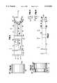
- FIG. 1is a top plan view of an instrument guide according to the present invention
- FIG. 2is a side view of the instrument guide of FIG. 1, the opposite side view being identical;
- FIG. 3is a transverse cross-section view taken through line 3--3 of FIG. 2;
- FIG. 4is a transverse cross-section view taken through line 4--4 of FIG. 2;
- FIG. 5is a top plan view of an alternative embodiment of an instrument guide according to the present invention.
- FIG. 6is a transverse cross-section view taken through line 6--6 of the instrument guide of FIG. 5;
- FIG. 7is a transverse cross-section view taken through line 7--7 of FIG. 5 of an alternative embodiment of an instrument guide according to the invention.
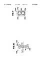
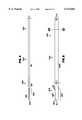
- FIG. 8is a side view of a centering guide
- FIG. 9is a top view of the centering guide of FIG. 8;
- FIG. 10is a transverse cross-section through line 10--10 of the centering guide of FIG. 8;
- FIG. 11is a perspective view of an alternative embodiment of an instrument guide according to the invention.
- FIG. 11ais a perspective side view of an alternative embodiment of a medial guide surface according to the invention.
- FIG. 12is a top view of the instrument guide of FIG. 11;
- FIG. 13is a cross-section view through line 13--13 of the instrument guide of FIG. 12;
- FIG. 14ais a top view of the instrument guide of FIG. 11 including an alternative embodiment of a medial guide surface
- FIG. 14bis a perspective side view of the medial guide surface illustrated in FIG. 14a;
- FIG. 15ais a top view of the instrument guide of FIG. 11 illustrating an alternative embodiment of the medial guide surface
- FIG. 16is a long side plan view of one embodiment of a stopping arrangement according to the invention.
- FIG. 17is a long side cross section view of the embodiment of a stopping arrangement illustrated in FIG. 16.
- the instruments and methods of the present inventionfacilitate the ease and accuracy of placement of multiple spinal implants into a vertebral space between opposing vertebrae.
- the complementary interaction of the herein disclosed component instrumentscan also reduce the number of intraoperative images needed to establish the relative alignment of the implants during an implant procedure.
- the ability to enhance the accuracy of alignment between two implants inserted into the intervertebral disc space according to the procedures of the inventionis facilitated by early establishment and continued maintenance of parallel operating fields at multiple implant sites.
- the instrumentation disclosedensures that the relative positioning of the implants is maintained throughout preparation of the bores that will receive the implants.
- the present inventionis directed to an instrument guide for guiding instruments used to prepare a site for implantation of a spinal fusion implant. While the herein disclosed instrument guides are particularly advantageous for performing fusions through a posterior approach, it will be appreciated that the instrument guides can also be used for anterior procedures.
- the disclosed instrument guidesinclude a proximal region and distal region.
- the proximal regionincluding openings for inserting instruments into the instrument guide and the distal region including components which are placed against the posterior surface of the vertebrae to be fused.
- the proximal region of the instrument guidecan also include affirmative stop arrangements for selectively controlling the depth of distal penetration of an instrument passed through the instrument guide.
- Such affirmative stop arrangements suitable for use with an instrument guide according to the present inventioninclude drill depth guides such as spacer caps disclosed in, for example, co-pending U.S. Ser. Nos. 09/081,240 and 09/116,747. Screw adjustable insertion guides such as disclosed in U.S. Ser. No. 08/921,001 can also be used. The disclosure of each of the foregoing patent applications are incorporated herein by reference.
- the distal end region of the instrument guidesinclude lateral instrument guide surfaces.
- the medial guide surfacesare retractable or removable.
- implantas used herein includes bone implants (e.g., autograft, allograft, artificial bone) and non-bone implants made from titanium or other implantable material.
- bone implantse.g., autograft, allograft, artificial bone
- non-bone implantsmade from titanium or other implantable material.
- FIG. 1is a top view of one embodiment of an instrument guide 10 according to the invention.
- Instrument guide 10provides for accurate relative alignment of parallel implants inserted from a posterior approach.
- Instrument guide 10includes a proximal region 1 and a distal region 2.
- the proximal region 1includes a first tubular lumen 3 and a second tubular lumen 4.
- Lumen walls 5 and 6, which surround lumens 3 and 4, respectively,are substantially complete. However, slots or other openings may be provided through the wall to facilitate cleaning or removal of debris from the instrument.
- Distal region 2 of instrument guide 10includes opposing lateral guide surfaces 11 and 12.
- First lateral guide surface 11forms a first partial wall 13 around the distal aspect of first lumen 3 which opens at the proximal end 1 of wall 5.
- second lateral guide surface 12forms a second partial wall 14 around the distal aspect of second lumen 4 which opens at the proximal end 1 of wall 6.
- a distal extension or paddles 19 and 20extend from the distal ends 21 and 22 of the first lateral guide surface 11 and second lateral guide surface 12, respectively.
- a tapered distal tip 23, 24is present at the distal end of each of paddles 19 and 20.
- the tapered distal tip 24 of wall 14is best appreciated in FIG. 2 which is a side view of instrument guide 10. The side view of the opposite side of instrument 10 is identical to that of FIG. 2.
- the tapered distal tips 23, 24 of paddles 19 and 20are optional.
- instrument guide 10is used with distraction plugs such as described in U.S. Pat. No. 5,489,307 or a central distracter such as described in co-pending U.S. Ser. Nos.
- tapered distal tips 23 and 24may not be present.
- tapered distal tips 23 and 24will facilitate insertion of the paddles between adjacent vertebrae. It will be appreciated that tapering the tips of paddles 19 and 20 can also facilitate placement of the paddles even when another distraction system is used.
- FIG. 3is a transverse cross-section through second partial wall 14 at line 3--3 and FIG. 4 is a transverse cross-section through paddle 20 at line 4--4.
- the transverse cross-section dimension T E of second partial wall 14is greater than the transverse cross-section dimension T D of distal extension 20.
- the shoulders 25, 26 formed at the transition between partial walls 13, 14 and paddles 19, 20provide an affirmative stop to the depth of penetration of paddles 19, 20 when the paddles are inserted into the intervertebral space.
- the transverse cross-section dimension T E of partial walls 13 and 14need only be greater than the transverse cross-section dimension T D of distal extension 19 and 20, respectively, by an amount sufficient to create a shoulder 25, 26 which can affirmatively stop the depth of penetration of instrument guide 10 into the intervertebral joint space.
- the length of distal extensions 19, 20are preferably less than the anterior-posterior dimension of the intervertebral space.
- an axial or medial aspect of lumen 3can be defined by medial guide surface 30.
- the medial guide surface 30is in the form of a first radiused guide wall 31.
- First radiused guide wall 31can be removable from instrument guide 10.
- a "removable" guide surfacemeans that the guide surface can be removed from the distal region 2 by removal from the instrument guide 10 or by retraction to a proximal position 1 or similar displacement which provides for selective presence or absence of a guide surface which opposes the lateral guide surfaces.
- radiused guide wall 31can selectively slide in the directions of arrow A such that some or all of the axial length of wall 31 lies over the exterior of wall 5 of first tubular lumen 3.
- the distal end 32 of radiused wall 31is in approximate transverse alignment with the distal end 21 of partial wall 13.
- the proximal end 33 of medial guide surface 30includes a handle 34 for grasping when sliding the medial guide surface 30 proximally or distally.
- radiused guide wall 31can be removed from its position opposing first lateral guide surface 11 and reinstalled to oppose second lateral guide surface 12.
- a second radiused guide wall 41forms a second medial guide surface 40 for second tubular lumen 4.
- the proximal end 43 of radiused guide wall 41can also include a handle 44 for grasping when sliding guide wall 41 proximally or distally.
- collar 53can be configured for mounting a drill depth guide such as a spacer cap as fully described in U.S. Ser. Nos. 09/116,747 and 09/081,240.
- each instrument guide 10is configured with a particular interior lumen diameter D 1 for passing reamers, taps, or implants of a selected diameter in close tolerance with the interior lumen guide surfaces.
- Suitable interior lumen diameters D 1can correspondence with an implant diameter of 3, 5, 7, 9, 11, 13, 15, 17, 19 or 21 mm as discussed in, for example U.S. Pat. No. 5,489,307.
- the transverse dimension T D of paddles 19 and 20can be configured to provide a predetermined distraction spacing between adjacent vertebrae.
- FIG. 5is a top view of an alternative embodiment of an instrument guide 100 according to the present invention, having a proximal region 101 and a distal region 102.
- the proximal region 101 of instrument guide 100includes a first tubular lumen 103 surrounded by lumen wall 104 and a second tubular lumen 105 surrounded by lumen wall 106.
- instrument guide 100also includes a first lateral guide surface 111 and a second lateral guide surface 112.
- First lateral guide surface 111forms a first partial wall 113 around the distal region of first lumen 103 and the second lateral guide surface 112 forms a second partial wall 114 around the distal region of lumen 105.
- Each lateral guide surface 111, 112has a distal end 115, 116, respectively.
- each lateral guide surface 111 and 112include a distal extension or paddles 117 and 118.
- a tapered distal endcan be present on paddles 117 and 118.
- Shoulders 121 and 122are present at the junction of distal ends 115, 116 and paddles 117, 118, respectively, as described above.
- medial guide surface 150 of instrument guide 100is provided by a hollow sleeve 151.
- the hollow sleeve of second tubular lumen 106is not visible as it is retracted within tubular lumen 106.
- the operation of the hollow sleeveswill be described by reference to sleeve 151 and lateral guide surface 111.
- Sleeve 151can move proximally and distally within the interior of lumen 103 in the directions of arrow A.
- Sleeve 151is illustrated in the distal extended position.
- handle 160By moving handle 160 in the proximal direction of arrow A, sleeve 151 can be slidably retracted within lumen 103.
- the distal end 162 of hollow sleeve 151is in transverse alignment with the distal end 115 of lateral guide surface 111.
- handle 160travels in track 161.
- the interior lumen diameter D 1 of sleeve 151is sized for passing instruments through the instrument guide to create the site for the size of the implant to be implanted.
- the exterior arc of wall 162 of hollow sleeve 151fits snugly with the interior arc of lateral guide surface 111 to limit substantial lateral movement.
- an instrument guide of the inventioncan include first and second tubular members wherein the tubular members are separable.
- a first tubular membersuch as lumen 3 surrounded by corresponding wall 5 and lateral guide surface 11
- a second tubular membersuch as lumen 4 surrounded by corresponding wall 6 and lateral guide surface 12
- the first and second tubular memberscan then be fixed in parallel alignment using a collar constructed and arranged for coupling the tubular members in a fixed arrangement to provide a desired alignment between the tubular members.
- Other features of an instrument guide having separable tubular members, including paddles, medial guide surfaces, etc.can be included as disclosed herein for other instrument guides.
- FIG. 6is a transverse cross-section through line 6--6 of FIG. 5.
- FIG. 7is a transverse cross-section through the location of line 7--7 of FIG. 5 of an alternative embodiment of an instrument guide 100a. Comparing FIGS. 6 and 7 it will be appreciated that in the embodiment of FIG. 7, lumen walls 104a, 106a surrounding tubular lumens 103a and 105a, respectively, arranged to form a space 200 between walls 104a and 106a. Space 200 is configured for cooperative fit with the cross-section configuration of the proximal end of a centering guide 300 such as that illustrated in FIGS. 8-10.
- an instrument guide of the inventionprovides for parallel insertion of spinal implants in close proximity. Examples of implants for close proximity insertion are disclosed in U.S. Pat. Nos. 5,658,337 and 5,609,636, the entire disclosures of which are incorporated herein by reference.
- instrument guide 400is illustrated in perspective view. Instrument guide 400 includes a proximal region 401 and a distal region 402. A first tubular lumen 403 and a second tubular lumen 404 are surrounded by lumen walls 405 and 406, respectively. At the distal region 402, instrument guide 400 includes first lateral guide surface 411 and second lateral guide surface 412.
- First lateral guide surface 411forms a partial wall 413 around the distal aspect of first lumen 403 and the second lateral guide surface 412 forms a second partial wall 414 around the distal aspect of second lumen 404.
- Distal extensions or paddles 420 and 421extend from the distal ends 423 and 424 of first lateral guide surface 411 and second lateral guide surface 412, respectively.
- Medial guide surface 450is described below.
- FIG. 12is a top view of instrument guide 400 showing medial guide surface 450 in the form of a sleeve 451 which can be passed into either lumen 403 or 404 after instrument guide 400 has been positioned at a location against the exterior surface of the vertebrae.
- FIG. 11ashows sleeve 451 separated from instrument guide 400.
- FIG. 13is a transverse cross-section view through line 13--13 of FIG. 12. As illustrated in FIG. 13, lumen walls 405 and 406 are incomplete at common region 460 where the circular geometry of lumen 403 and 404 overlap one another. The overlapping geometry of the cross-sectional surface area of lumens 403 and 404 provides for reduced spacing between the longitudinal axes of parallel spinal fusion implants when instrument guide 400 is used for preparing the implant sites.
- sleeve 451can be passed into lumen 403 for preparing a first implant site and insertion of a first implant.
- Sleeve 451can subsequently be removed and inserted into lumen 404 for preparing a second implant site and insertion of a second implant.
- Distraction plugs, obturators, reamers, taps, drill depth guides, and other instrumentation suitable for use with instrument guide 400are fully disclosed in co-pending U.S. Ser. No. 09/081,240, the entire disclosure of which is incorporated herein by reference.
- FIGS. 14-15illustrate alternative sleeve embodiments 451a and 451b.
- sleeve 451acan include an anchoring arrangement 460 comprising a tooth 461 which can be embedded into the exterior surface of the vertebrae to facilitate maintenance of the position of instrument guide 400a when at a desired location.
- a second toothcan be positioned diametrically opposed to first tooth 461. Additional teeth can also be used.
- FIGS. 15 and 15aillustrate sleeve 451b including paddle 470.
- paddles 470can assist distraction as well as facilitate increased maintenance of the position of instrument guide 400b when in a desired location.
- the proximal ends of the disclosed instrument guidescan include arrangements for controlling the depth of penetration of instruments passed through the instrument guide. Any suitable arrangement providing an affirmative stop system can be used. Preferred systems include spacer caps and screw type systems as disclosed in U.S. Ser. No. 09/116,747.
- One embodiment of an arrangement for controlling the depth of penetration of instrumentsis a stopping arrangement 500 such as spacer cap 501 illustrated in long side plan view in FIG. 16.
- spaver cap 501is oriented for placement at the proximal end of collar 53 of instrument guide 10 in FIG. 1.
- a long side cross section of spacer cap 501is shown in FIG. 17.
- spacer cap 501includes a shoulder 502 projecting axially from wall 503 surrounding lumen 504 of spacer cap 501.
- the instrument guides of the present inventioncan be used for posterior or anterior approaches to the vertebral column.
- the disclosed instrument guidesare particularly advantageous for use when implanting a spinal fusion implant through a posterior approach.
- Known methodscan be used for anesthetizing, positioning and preparing the patient for surgery.
- Most surgical techniques using the instrument guides of the inventionwill include a bilateral laminectomy of sufficient size to accommodate the exterior dimensions of the instrument guide.
- the distal extension or paddles of instrument guides 10, 100 of the inventionare used to distract the intervertebral space between adjacent vertebrae.
- the instrument guide to be usedis selected based on a desired lumen diameter and paddle dimension.
- the interior diameter of the lumen D 1 and the transverse dimension of the paddle T Dare selected based on the size of the implant and the amount of distraction needed for the particular intervertebral space. Methods for determining the amount of intervertebral distraction and implant size are within the knowledge of one skilled in the art.
- the central axis C A of the instrument guide(FIGS. 1 and 5) is aligned with the midsagittal plane of the intervertebral disc space.
- the tapered distal tips of the paddlesare placed against the posterior aspect of the disc with the cauda equina between and safely away from the paddles. Slits can be cut into the disc with a scalpel blade to mark the location of entry for the tapered distal tips of the paddles.
- the angular orientation of the instrument guideis confirmed and the proximal end of the instrument guide tapped to insert the paddles into the intervertebral space until the depth of insertion is affirmatively stopped by the shoulders at the junction between the paddles and the distal end of the lateral guide surfaces.
- the surgeonselects the side of the intervertebral space to be prepared first and the cauda equina is retracted laterally to the opposite side.
- the medial guide surfacesuch as radiused guide wall 31 or sleeves 151, 451, 451a or 451b, is advanced distally until the distal end of the medial guide surface contacts the posterior aspect of the vertebrae.
- the medial and lateral guide surfaces surrounding the lumenprovide guidance for passing reamers, taps and the implant from the proximal region of the instrument guide through the distal region to prepare a site and implant an implant.
- the cauda equinais retracted laterally over the completed first side and the procedure is repeated on the opposite side of the intervertebral space.
- the instrument guide 10, 100can be used with the instruments disclosed in U.S. Pat. No. 5,489,307. After the surgeon has selected the appropriate implant size, the dura and cauda equina are retracted laterally over the first side of the intervertebral space to be implanted. At the second side, with the cauda equina and nerve roots clear, the appropriate sized distraction plug is selected and inserted as described in U.S. Pat. No. 5,489,307. After the distraction plug is inserted on the second side, the cauda equina is retracted laterally over the first side and a distraction plug is placed at the first side of the intervertebral space.
- a tube guidecan be threaded onto the proximal end of the first side distraction plug.
- the retraction of the cauda equinais released and after confirming the dura and nerve roots are clear, the instrument guide 10, 100 is passed over the drill guide until the paddles are positioned lateral to the lateral aspect of each distraction plug at the posterior aspect of the disc space.
- slitscan be cut into the disc with a scalpel blade to mark the location of entry of the paddles into the disc space.
- the instrument guidecan then be tapped lightly until the shoulders at the distal end of the lateral guide surface affirmatively stop distal advancement.
- the cauda equinais then retracted over the distraction plug on the second side.
- the medial guide surfacesuch as radiused guide wall 31 or sleeves 151, 451, 451a or 451b, on the first side is advanced distally before or after removal of the distraction plug.
- the implant sitecan then be prepared through the instrument guide lumen as described above and in U.S. Pat. No. 5,489,307. After completion of the first side, the medial guide surface is removed or retracted proximally and the cauda equina retracted laterally over the first implant and the procedure is repeated on the opposite side.
- instrument guidecan be positioned after insertion of one distraction plug and one drill guide, after insertion of two distraction plugs and no drill guide or after insertion of two distraction plugs and one drill guide, etc.
- an instrument guide according to the present inventioncan be used with a centering guide as illustrated in FIGS. 7-10 and fully described in U.S. Ser. No. 08/921,001.
- Centering guide 300is a rigid rod extending from a distal end 302 to a proximal end 303 along a longitudinal axis X 1 --X 1 .
- the distal end 302is rounded at the distal tip 304 to facilitate easy insertion of the distal end 302 into the disc space.
- the distraction portion 305 of the distal end 302is defined by parallel and spaced-apart side edges 308 which are spaced apart by a distance equal to the desired distraction of the vertebrae.
- the side edges 308act against the end plates of the opposing vertebrae to urge the vertebrae apart.
- the end plateshold the centering guide 300 with the X 1 --X 1 axis centrally positioned between the end plates.
- proximal end 303can be moved left or right relative to the vertebrae, the precise central positioning of the proximal end 303 can be determined through x-ray analysis following placement of the centering guide 300 such that a surgeon can be assured that the longitudinal axis X 1 --X 1 extends perpendicular to a transverse plane of the vertebrae.
- FIG. 10which is a cross-section through 10--10 of FIG. 8, extending between side edges 309 of the proximal end 303 and extending the length from end 302 to end 303, are left and right (or first and second) lateral surfaces 310 and 311.
- the lateral surfaces 310 and 311are concave and have a radius of curvature equal to a radius of curvature of the exterior wall 104a and 106a of instrument guide 100a of FIG. 7. That is, the cross-sectional configuration of the proximal end 303 of centering guide 300, as illustrated in FIG. 10, is configured to slide within space 200 of FIG. 7.
- the cauda equinais retracted to one side and centering guide 300 is inserted along the midsagittal plane of the intervertebral space with edges 308 facing cranially and caudally to urge the vertebrae to the desired amount of distraction.
- the distraction portion 305can have a diverging or converging taper, relative to the longitudinal axis X 1 --X 1 to create a desired degree of lordosis.
- the distal end 302includes stops 312 of the illustrated embodiment to affirmatively stop distal advancement of centering guide 300 into the intervertebral space.
- the retraction of the cauda equinacan be released and guide tube 100a can be slid over the proximal region 304 of centering guide 300 until the paddles abut the posterior aspect of the intervertebral space. Slits can be cut into the disc with a scalpel to mark the location where the paddles will be inserted into the disc space. After confirming that the cauda equina and nerve roots are clear, the instrument guide is tapped to urge the paddles into the intervertebral space until the shoulders at the distal end of the lateral guide affirmatively stop distal advancement.
Landscapes
- Health & Medical Sciences (AREA)
- Orthopedic Medicine & Surgery (AREA)
- Life Sciences & Earth Sciences (AREA)
- Biomedical Technology (AREA)
- Engineering & Computer Science (AREA)
- Veterinary Medicine (AREA)
- Transplantation (AREA)
- Surgery (AREA)
- Oral & Maxillofacial Surgery (AREA)
- Heart & Thoracic Surgery (AREA)
- Public Health (AREA)
- General Health & Medical Sciences (AREA)
- Animal Behavior & Ethology (AREA)
- Molecular Biology (AREA)
- Medical Informatics (AREA)
- Dentistry (AREA)
- Neurology (AREA)
- Physical Education & Sports Medicine (AREA)
- Nuclear Medicine, Radiotherapy & Molecular Imaging (AREA)
- Cardiology (AREA)
- Vascular Medicine (AREA)
- Prostheses (AREA)
Abstract
Description
Claims (20)
Priority Applications (1)
| Application Number | Priority Date | Filing Date | Title |
|---|---|---|---|
| US09/276,982US6113602A (en) | 1999-03-26 | 1999-03-26 | Posterior spinal instrument guide and method |
Applications Claiming Priority (1)
| Application Number | Priority Date | Filing Date | Title |
|---|---|---|---|
| US09/276,982US6113602A (en) | 1999-03-26 | 1999-03-26 | Posterior spinal instrument guide and method |
Publications (1)
| Publication Number | Publication Date |
|---|---|
| US6113602Atrue US6113602A (en) | 2000-09-05 |
Family
ID=23058952
Family Applications (1)
| Application Number | Title | Priority Date | Filing Date |
|---|---|---|---|
| US09/276,982Expired - Fee RelatedUS6113602A (en) | 1999-03-26 | 1999-03-26 | Posterior spinal instrument guide and method |
Country Status (1)
| Country | Link |
|---|---|
| US (1) | US6113602A (en) |
Cited By (193)
| Publication number | Priority date | Publication date | Assignee | Title |
|---|---|---|---|---|
| US6224607B1 (en)* | 1999-01-25 | 2001-05-01 | Gary K. Michelson | Instrumentation and method for creating an intervertebral space for receiving an implant |
| US6224599B1 (en)* | 1999-05-19 | 2001-05-01 | Matthew G. Baynham | Viewable wedge distractor device |
| WO2001049188A1 (en)* | 2000-01-06 | 2001-07-12 | Spinal Concepts, Inc. | Instrument and method for implanting an interbody fusion device |
| WO2001028437A3 (en)* | 1999-10-18 | 2001-12-06 | Sulzer Spine Tech Inc | Spinal surgery instruments and methods |
| US6383191B1 (en)* | 2000-03-15 | 2002-05-07 | Sdgi Holdings, Inc. | Laparoscopic instrument sleeve |
| US6436141B2 (en) | 2000-04-07 | 2002-08-20 | Surgical Dynamics, Inc. | Apparatus for fusing adjacent bone structures |
| US20020138147A1 (en)* | 2001-03-22 | 2002-09-26 | Surgical Dynamics, Inc. | Apparatus for fusing adjacent bone structures |
| US20020161366A1 (en)* | 2000-12-29 | 2002-10-31 | Bruce Robie | Instrument system for preparing a disc space between adjacent vertebral bodies to receive a repair device |
| US6478800B1 (en)* | 2000-05-08 | 2002-11-12 | Depuy Acromed, Inc. | Medical installation tool |
| US6514260B1 (en)* | 2000-03-15 | 2003-02-04 | Sdgi Holdings, Inc. | Methods and instruments for laparoscopic spinal surgery |
| US20030032966A1 (en)* | 1999-10-20 | 2003-02-13 | Foley Kevin T. | Methods and instrumentation for distraction of a disc space |
| WO2003020137A1 (en)* | 2001-08-31 | 2003-03-13 | Sdgi Holdings, Inc, | Methods and instrumentation for vertebral interbody fusion |
| US6540753B2 (en) | 2001-03-23 | 2003-04-01 | Howmedica Osteonics Corp. | Instrumentation for implant insertion |
| US20030083689A1 (en)* | 2001-10-30 | 2003-05-01 | Simonson Robert E. | Non cannulated dilators |
| US20030097181A1 (en)* | 1999-04-07 | 2003-05-22 | Salvatore Castro | Low profile fusion cage and insertion set |
| US6575981B1 (en) | 1999-02-04 | 2003-06-10 | Sdgi Holdings, Inc. | Methods and instrumentation for vertebral interbody fusion |
| US6575899B1 (en) | 1999-10-20 | 2003-06-10 | Sdgi Holdings, Inc. | Methods and instruments for endoscopic interbody surgical techniques |
| US6582437B2 (en) | 1999-08-26 | 2003-06-24 | Sdgi Holdings, Inc. | Devices and methods for implanting fusion cages |
| US6635062B2 (en) | 1998-04-09 | 2003-10-21 | Sdgi Holdings, Inc. | Methods and instrumentation for vertebral interbody fusion |
| US6648895B2 (en) | 2000-02-04 | 2003-11-18 | Sdgi Holdings, Inc. | Methods and instrumentation for vertebral interbody fusion |
| US6666891B2 (en)* | 2000-11-13 | 2003-12-23 | Frank H. Boehm, Jr. | Device and method for lumbar interbody fusion |
| US20030236447A1 (en)* | 2001-01-29 | 2003-12-25 | Stephen Ritland | Retractor and method for spinal pedicle screw placement |
| US6692434B2 (en) | 2000-09-29 | 2004-02-17 | Stephen Ritland | Method and device for retractor for microsurgical intermuscular lumbar arthrodesis |
| US6719794B2 (en) | 2001-05-03 | 2004-04-13 | Synthes (U.S.A.) | Intervertebral implant for transforaminal posterior lumbar interbody fusion procedure |
| US20040097932A1 (en)* | 1998-04-09 | 2004-05-20 | Ray Eddie F. | Methods and instrumentation for vertebral interbody fusion |
| US6743234B2 (en) | 1999-02-04 | 2004-06-01 | Sdgi Holdings, Inc. | Methods and instrumentation for vertebral interbody fusion |
| US20040176848A1 (en)* | 2003-03-06 | 2004-09-09 | Rafail Zubok | Cervical disc replacement method |
| US20040193272A1 (en)* | 2003-03-06 | 2004-09-30 | Rafail Zubok | Instrumentation and methods for use in implanting a cervical disc replacement device |
| US20040204716A1 (en)* | 2003-04-09 | 2004-10-14 | Jonathan Fanger | Drill guide with alignment feature |
| US20050043740A1 (en)* | 2003-08-20 | 2005-02-24 | Haid Regis W. | Technique and instrumentation for preparation of vertebral members |
| US20050055095A1 (en)* | 2001-07-16 | 2005-03-10 | Errico Joseph P. | Artificial intervertebral disc trials having a cylindrical engagement surface |
| US20050105385A1 (en)* | 2003-11-18 | 2005-05-19 | Scimed Life Systems, Inc. | Apparatus for mixing and dispensing a multi-component bone cement |
| US6929647B2 (en) | 2001-02-21 | 2005-08-16 | Howmedica Osteonics Corp. | Instrumentation and method for implant insertion |
| US20050203625A1 (en)* | 2000-11-13 | 2005-09-15 | Boehm Frank H.Jr. | Device and method for lumbar interbody fusion |
| US20050216002A1 (en)* | 2001-10-30 | 2005-09-29 | Depuy Spine, Inc. | Configured and sized cannula |
| US6951538B2 (en) | 2001-01-29 | 2005-10-04 | Depuy Spine, Inc. | Retractor and method for spinal pedicle screw placement |
| US6966910B2 (en) | 2002-04-05 | 2005-11-22 | Stephen Ritland | Dynamic fixation device and method of use |
| US6974480B2 (en) | 2001-05-03 | 2005-12-13 | Synthes (Usa) | Intervertebral implant for transforaminal posterior lumbar interbody fusion procedure |
| US6991632B2 (en) | 2001-09-28 | 2006-01-31 | Stephen Ritland | Adjustable rod and connector device and method of use |
| US20060036261A1 (en)* | 2004-08-13 | 2006-02-16 | Stryker Spine | Insertion guide for a spinal implant |
| US20060052794A1 (en)* | 2004-08-17 | 2006-03-09 | Scimed Life Systems, Inc. | Apparatus and methods for delivering compounds into vertebrae for vertebroplasty |
| US20060202242A1 (en)* | 2005-03-09 | 2006-09-14 | Sony Corporation | Solid-state imaging device |
| US7118580B1 (en) | 1999-09-14 | 2006-10-10 | Spine Solutions Inc. | Instrument for inserting intervertebral implants |
| US20060271055A1 (en)* | 2005-05-12 | 2006-11-30 | Jeffery Thramann | Spinal stabilization |
| US20060271048A1 (en)* | 2005-05-12 | 2006-11-30 | Jeffery Thramann | Pedicle screw based vertebral body stabilization apparatus |
| US7166073B2 (en) | 2000-09-29 | 2007-01-23 | Stephen Ritland | Method and device for microsurgical intermuscular spinal surgery |
| US7179261B2 (en) | 2003-12-16 | 2007-02-20 | Depuy Spine, Inc. | Percutaneous access devices and bone anchor assemblies |
| US20070055379A1 (en)* | 2005-08-03 | 2007-03-08 | Stone Corbett W | Annular access devices |
| US7207992B2 (en) | 2001-09-28 | 2007-04-24 | Stephen Ritland | Connection rod for screw or hook polyaxial system and method of use |
| US20070100347A1 (en)* | 2005-10-31 | 2007-05-03 | Stad Shawn D | Arthroplasty revision device and method |
| US20070123904A1 (en)* | 2005-10-31 | 2007-05-31 | Depuy Spine, Inc. | Distraction instrument and method for distracting an intervertebral site |
| US20070162134A1 (en)* | 2002-12-13 | 2007-07-12 | Theirry Marnay | Intervertebral implant, insertion tool and method of inserting same |
| US20070161997A1 (en)* | 2005-05-12 | 2007-07-12 | Lanx, Llc | Dynamic spinal stabilization |
| US20070203500A1 (en)* | 2006-02-28 | 2007-08-30 | Vermillion Technologies, Llc | Apparatus and method of shaping an intervertebral space |
| US20070233076A1 (en)* | 2006-03-31 | 2007-10-04 | Sdgi Holdings, Inc. | Methods and instruments for delivering interspinous process spacers |
| US20070282340A1 (en)* | 2005-02-17 | 2007-12-06 | Malandain Hugues F | Percutaneous spinal implants and methods |
| US20070299526A1 (en)* | 2005-02-17 | 2007-12-27 | Malandain Hugues F | Percutaneous spinal implants and methods |
| US20080027552A1 (en)* | 1997-01-02 | 2008-01-31 | Zucherman James F | Spine distraction implant and method |
| US20080027433A1 (en)* | 2005-02-17 | 2008-01-31 | Kohm Andrew C | Percutaneous spinal implants and methods |
| US20080039853A1 (en)* | 1997-01-02 | 2008-02-14 | Zucherman James F | Spine distraction implant and method |
| US20080097454A1 (en)* | 2006-09-19 | 2008-04-24 | Warsaw Orthopedic Inc. | Instruments and methods for spinal implant revision |
| US20080177298A1 (en)* | 2006-10-24 | 2008-07-24 | St. Francis Medical Technologies, Inc. | Tensioner Tool and Method for Implanting an Interspinous Process Implant Including a Binder |
| US20080200986A1 (en)* | 2003-08-01 | 2008-08-21 | Spinal Kinetics, Inc. | Method and a Kit for Inserting Prosthetic Intervertebral Discs into a Spine |
| US7416553B2 (en) | 2003-04-09 | 2008-08-26 | Depuy Acromed, Inc. | Drill guide and plate inserter |
| US7455639B2 (en) | 2004-09-20 | 2008-11-25 | Stephen Ritland | Opposing parallel bladed retractor and method of use |
| US7497859B2 (en)* | 2002-10-29 | 2009-03-03 | Kyphon Sarl | Tools for implanting an artificial vertebral disk |
| US7563284B2 (en) | 2002-08-15 | 2009-07-21 | Synthes Usa, Llc | Intervertebral disc implant |
| US20090234397A1 (en)* | 2004-11-22 | 2009-09-17 | Petersen David A | Methods and Surgical Kits for Minimally-Invasive Facet Joint Fusion |
| US7637952B2 (en) | 2002-03-11 | 2009-12-29 | Zimmer Spine, Inc. | Instrumentation and procedure for implanting spinal implant devices |
| US7682375B2 (en) | 2002-05-08 | 2010-03-23 | Stephen Ritland | Dynamic fixation device and method of use |
| US7713302B2 (en) | 2001-10-01 | 2010-05-11 | Spinecore, Inc. | Intervertebral spacer device utilizing a spirally slotted belleville washer having radially spaced concentric grooves |
| US7753939B2 (en) | 2000-06-30 | 2010-07-13 | Stephen Ritland | Polyaxial connection device and method |
| US7763047B2 (en) | 2002-02-20 | 2010-07-27 | Stephen Ritland | Pedicle screw connector apparatus and method |
| US7771477B2 (en) | 2001-10-01 | 2010-08-10 | Spinecore, Inc. | Intervertebral spacer device utilizing a belleville washer having radially spaced concentric grooves |
| US20100204798A1 (en)* | 2005-10-21 | 2010-08-12 | Stryker Spine | System and method for fusion cage implantation |
| US7776047B2 (en)* | 2003-04-09 | 2010-08-17 | Depuy Spine, Inc. | Guide for spinal tools, implants, and devices |
| US7799081B2 (en) | 2004-09-14 | 2010-09-21 | Aeolin, Llc | System and method for spinal fusion |
| US7803162B2 (en) | 2003-07-21 | 2010-09-28 | Spine Solutions, Inc. | Instruments and method for inserting an intervertebral implant |
| US7824410B2 (en) | 2001-10-30 | 2010-11-02 | Depuy Spine, Inc. | Instruments and methods for minimally invasive spine surgery |
| US7909848B2 (en) | 2003-06-27 | 2011-03-22 | Depuy Spine, Inc. | Tissue retractor and guide device |
| US7909829B2 (en) | 2003-06-27 | 2011-03-22 | Depuy Spine, Inc. | Tissue retractor and drill guide |
| US7909843B2 (en) | 2004-06-30 | 2011-03-22 | Thompson Surgical Instruments, Inc. | Elongateable surgical port and dilator |
| US7918858B2 (en) | 2006-09-26 | 2011-04-05 | Depuy Spine, Inc. | Minimally invasive bone anchor extensions |
| US7927354B2 (en) | 2005-02-17 | 2011-04-19 | Kyphon Sarl | Percutaneous spinal implants and methods |
| US7955392B2 (en) | 2006-12-14 | 2011-06-07 | Warsaw Orthopedic, Inc. | Interspinous process devices and methods |
| US7959564B2 (en) | 2006-07-08 | 2011-06-14 | Stephen Ritland | Pedicle seeker and retractor, and methods of use |
| USRE42525E1 (en) | 1999-03-12 | 2011-07-05 | Depuy Spine, Inc. | Cannula and sizing insertion method |
| US20110190892A1 (en)* | 2010-02-01 | 2011-08-04 | X-Spine Systems, Inc. | Spinal implant co-insertion system and method |
| US7993342B2 (en) | 2005-02-17 | 2011-08-09 | Kyphon Sarl | Percutaneous spinal implants and methods |
| US8021392B2 (en)* | 2004-11-22 | 2011-09-20 | Minsurg International, Inc. | Methods and surgical kits for minimally-invasive facet joint fusion |
| US8021399B2 (en) | 2005-07-19 | 2011-09-20 | Stephen Ritland | Rod extension for extending fusion construct |
| US8029568B2 (en) | 2001-10-18 | 2011-10-04 | Spinecore, Inc. | Intervertebral spacer device having a slotted partial circular domed arch strip spring |
| US8029567B2 (en) | 2005-02-17 | 2011-10-04 | Kyphon Sarl | Percutaneous spinal implants and methods |
| US8038713B2 (en) | 2002-04-23 | 2011-10-18 | Spinecore, Inc. | Two-component artificial disc replacements |
| US8088163B1 (en) | 2008-02-06 | 2012-01-03 | Kleiner Jeffrey B | Tools and methods for spinal fusion |
| US8096995B2 (en) | 2005-02-17 | 2012-01-17 | Kyphon Sarl | Percutaneous spinal implants and methods |
| US8096994B2 (en) | 2005-02-17 | 2012-01-17 | Kyphon Sarl | Percutaneous spinal implants and methods |
| US8114131B2 (en) | 2008-11-05 | 2012-02-14 | Kyphon Sarl | Extension limiting devices and methods of use for the spine |
| USD656610S1 (en) | 2009-02-06 | 2012-03-27 | Kleiner Jeffrey B | Spinal distraction instrument |
| WO2012040152A1 (en) | 2010-09-20 | 2012-03-29 | Jeffrey Kleiner | Fusion cage with combined biological delivery system |
| US8167890B2 (en) | 2005-02-17 | 2012-05-01 | Kyphon Sarl | Percutaneous spinal implants and methods |
| US8262571B2 (en) | 2003-05-22 | 2012-09-11 | Stephen Ritland | Intermuscular guide for retractor insertion and method of use |
| US8277507B2 (en) | 2002-04-12 | 2012-10-02 | Spinecore, Inc. | Spacerless artificial disc replacements |
| WO2012145048A1 (en) | 2011-04-20 | 2012-10-26 | Spinewindow Llc | Method and apparatus for performing retro peritoneal dissection |
| US8303601B2 (en) | 2006-06-07 | 2012-11-06 | Stryker Spine | Collet-activated distraction wedge inserter |
| WO2012162600A2 (en) | 2011-05-26 | 2012-11-29 | Strauch Eric | Surgical drape with separable elements |
| US20120310293A1 (en)* | 2008-10-16 | 2012-12-06 | Aesculap Implant Systems, Llc. | Surgical instrument and method of use for inserting an implant between two bones |
| US8337500B2 (en) | 2006-07-31 | 2012-12-25 | Synthes Usa, Llc | Drilling/milling guide and keel cut preparation system |
| US8366772B2 (en) | 2002-04-23 | 2013-02-05 | Spinecore, Inc. | Artificial disc replacements with natural kinematics |
| US8366748B2 (en) | 2008-12-05 | 2013-02-05 | Kleiner Jeffrey | Apparatus and method of spinal implant and fusion |
| US8377072B2 (en) | 2006-02-06 | 2013-02-19 | Depuy Spine, Inc. | Medical device installation tool |
| US8414588B2 (en) | 2007-10-04 | 2013-04-09 | Depuy Spine, Inc. | Methods and devices for minimally invasive spinal connection element delivery |
| US8425603B2 (en) | 2008-12-22 | 2013-04-23 | Synthes Usa, Llc | Orthopedic implant with flexible keel |
| US8435301B2 (en) | 2002-08-15 | 2013-05-07 | DePuy Synthes Products, LLC | Artificial intervertebral disc implant |
| US8480715B2 (en) | 2007-05-22 | 2013-07-09 | Zimmer Spine, Inc. | Spinal implant system and method |
| US8506636B2 (en) | 2006-09-08 | 2013-08-13 | Theken Spine, Llc | Offset radius lordosis |
| US8506634B2 (en) | 1999-07-02 | 2013-08-13 | DePuy Synthes Products, LLC | Intervertebral implant |
| US8663229B2 (en) | 2003-04-28 | 2014-03-04 | DePuy Synthes Products, LLC | Instruments and method for preparing an intervertebral space for receiving an artificial disc implant |
| US8685031B2 (en) | 2009-09-18 | 2014-04-01 | Spinal Surgical Strategies, Llc | Bone graft delivery system |
| US8740941B2 (en) | 2006-11-10 | 2014-06-03 | Lanx, Inc. | Pedicle based spinal stabilization with adjacent vertebral body support |
| US8840617B2 (en) | 2010-02-26 | 2014-09-23 | Warsaw Orthopedic, Inc. | Interspinous process spacer diagnostic parallel balloon catheter and methods of use |
| US8864830B2 (en) | 2013-03-12 | 2014-10-21 | Spine Wave, Inc. | Apparatus and methods for inserting an interbody fusion device |
| US8906028B2 (en) | 2009-09-18 | 2014-12-09 | Spinal Surgical Strategies, Llc | Bone graft delivery device and method of using the same |
| USD723682S1 (en) | 2013-05-03 | 2015-03-03 | Spinal Surgical Strategies, Llc | Bone graft delivery tool |
| US8998990B2 (en) | 2006-07-24 | 2015-04-07 | DePuy Synthes Products, LLC | Intervertebral implant with keel |
| US9034046B2 (en) | 2007-10-30 | 2015-05-19 | Aesculap Implant Systems, Llc | Vertebral body replacement device and method for use to maintain a space between two vertebral bodies within a spine |
| US9060877B2 (en) | 2009-09-18 | 2015-06-23 | Spinal Surgical Strategies, Llc | Fusion cage with combined biological delivery system |
| US9072554B2 (en) | 2005-09-21 | 2015-07-07 | Children's Hospital Medical Center | Orthopedic implant |
| US9173694B2 (en) | 2009-09-18 | 2015-11-03 | Spinal Surgical Strategies, Llc | Fusion cage with combined biological delivery system |
| US9186193B2 (en) | 2009-09-18 | 2015-11-17 | Spinal Surgical Strategies, Llc | Fusion cage with combined biological delivery system |
| US9204906B2 (en) | 2009-10-22 | 2015-12-08 | Nuvasive, Inc. | Posterior cervical fusion system and techniques |
| US9204909B2 (en) | 2011-07-13 | 2015-12-08 | Warsaw Orthopedic, Inc. | Spinal rod system and method |
| WO2015187397A1 (en) | 2013-06-07 | 2015-12-10 | George Frey | Patient-matched apparatus and methods for performing surgical procedures |
| US9247943B1 (en) | 2009-02-06 | 2016-02-02 | Kleiner Intellectual Property, Llc | Devices and methods for preparing an intervertebral workspace |
| USD750249S1 (en) | 2014-10-20 | 2016-02-23 | Spinal Surgical Strategies, Llc | Expandable fusion cage |
| US9629729B2 (en) | 2009-09-18 | 2017-04-25 | Spinal Surgical Strategies, Llc | Biological delivery system with adaptable fusion cage interface |
| US9717403B2 (en) | 2008-12-05 | 2017-08-01 | Jeffrey B. Kleiner | Method and apparatus for performing retro peritoneal dissection |
| CN106999216A (en)* | 2014-05-28 | 2017-08-01 | 普罗维登斯医疗技术公司 | Lateral mass fixed system |
| USD797290S1 (en) | 2015-10-19 | 2017-09-12 | Spinal Surgical Strategies, Llc | Bone graft delivery tool |
| US9883874B1 (en)* | 2013-03-08 | 2018-02-06 | Vg Innovations, Llc | Tool and method for implanting fusion device into sacroiliac joint |
| US9895176B2 (en) | 2012-09-24 | 2018-02-20 | VGI Medical, LLC | Method for deploying a fusion device for sacroiliac joint fusion |
| US9987024B2 (en) | 2010-06-29 | 2018-06-05 | Mighty Oak Medical, Inc. | Patient-matched apparatus and methods for performing surgical procedures |
| US10039649B2 (en) | 2008-06-06 | 2018-08-07 | Providence Medical Technology, Inc. | Composite spinal facet implant with textured surfaces |
| EP3357459A1 (en) | 2017-02-03 | 2018-08-08 | Spinal Surgical Strategies, LLC | Bone graft delivery device with positioning handle |
| US10098674B2 (en) | 2009-10-22 | 2018-10-16 | Nuvasive, Inc. | System and method for posterior cervical fusion |
| US10149673B2 (en) | 2008-06-06 | 2018-12-11 | Providence Medical Technology, Inc. | Facet joint implants and delivery tools |
| US10172721B2 (en) | 2008-06-06 | 2019-01-08 | Providence Technology, Inc. | Spinal facet cage implant |
| US10201375B2 (en) | 2014-05-28 | 2019-02-12 | Providence Medical Technology, Inc. | Lateral mass fixation system |
| USD841165S1 (en) | 2015-10-13 | 2019-02-19 | Providence Medical Technology, Inc. | Cervical cage |
| US10219910B2 (en) | 2006-12-29 | 2019-03-05 | Providence Medical Technology, Inc. | Cervical distraction method |
| US10226285B2 (en) | 2008-06-06 | 2019-03-12 | Providence Medical Technology, Inc. | Vertebral joint implants and delivery tools |
| US10238501B2 (en) | 2008-06-06 | 2019-03-26 | Providence Medical Technology, Inc. | Cervical distraction/implant delivery device |
| US10245159B1 (en) | 2009-09-18 | 2019-04-02 | Spinal Surgical Strategies, Llc | Bone graft delivery system and method for using same |
| US10327910B2 (en) | 2013-03-14 | 2019-06-25 | X-Spine Systems, Inc. | Spinal implant and assembly |
| USD853560S1 (en) | 2008-10-09 | 2019-07-09 | Nuvasive, Inc. | Spinal implant insertion device |
| US10363108B2 (en) | 2010-06-07 | 2019-07-30 | Creative Surgical Solutions, Llc | Surgical drape with separable elements |
| USD857893S1 (en) | 2017-10-26 | 2019-08-27 | Mighty Oak Medical, Inc. | Cortical surgical guide |
| USD858765S1 (en) | 2017-10-26 | 2019-09-03 | Mighty Oak Medical, Inc. | Cortical surgical guide |
| US10653454B2 (en) | 2007-07-13 | 2020-05-19 | Mighty Oak Medical, Inc. | Spinal fixation systems |
| US10682243B2 (en) | 2015-10-13 | 2020-06-16 | Providence Medical Technology, Inc. | Spinal joint implant delivery device and system |
| USD887552S1 (en) | 2016-07-01 | 2020-06-16 | Providence Medical Technology, Inc. | Cervical cage |
| US10743890B2 (en) | 2016-08-11 | 2020-08-18 | Mighty Oak Medical, Inc. | Drill apparatus and surgical fixation devices and methods for using the same |
| USD895111S1 (en) | 2018-06-04 | 2020-09-01 | Mighty Oak Medical, Inc. | Sacro-iliac guide |
| EP3689273A3 (en)* | 2011-04-21 | 2020-09-16 | Synthes GmbH | Spline oriented indexing guide |
| USD911525S1 (en) | 2019-06-21 | 2021-02-23 | Providence Medical Technology, Inc. | Spinal cage |
| USRE48501E1 (en) | 2012-10-23 | 2021-04-06 | Providence Medical Technology, Inc. | Cage spinal implant |
| US10973656B2 (en) | 2009-09-18 | 2021-04-13 | Spinal Surgical Strategies, Inc. | Bone graft delivery system and method for using same |
| US11039889B2 (en) | 2010-06-29 | 2021-06-22 | Mighty Oak Medical, Inc. | Patient-matched apparatus and methods for performing surgical procedures |
| US11065039B2 (en) | 2016-06-28 | 2021-07-20 | Providence Medical Technology, Inc. | Spinal implant and methods of using the same |
| USD933230S1 (en) | 2019-04-15 | 2021-10-12 | Providence Medical Technology, Inc. | Cervical cage |
| US11185382B2 (en) | 2017-08-31 | 2021-11-30 | Creative Surgical Solutions, Llc | Separable sterile drape with z-shaped folds |
| US20210386434A1 (en)* | 2018-09-21 | 2021-12-16 | Providence Medical Technology, Inc. | Vertebral joint access and decortication devices and methods of using |
| US11224521B2 (en) | 2008-06-06 | 2022-01-18 | Providence Medical Technology, Inc. | Cervical distraction/implant delivery device |
| USD945621S1 (en) | 2020-02-27 | 2022-03-08 | Providence Medical Technology, Inc. | Spinal cage |
| US11272964B2 (en) | 2008-06-06 | 2022-03-15 | Providence Medical Technology, Inc. | Vertebral joint implants and delivery tools |
| USD948717S1 (en) | 2018-06-04 | 2022-04-12 | Mighty Oak Medical, Inc. | Sacro-iliac guide |
| US11376073B2 (en) | 2010-06-29 | 2022-07-05 | Mighty Oak Medical Inc. | Patient-matched apparatus and methods for performing surgical procedures |
| US11419642B2 (en) | 2003-12-16 | 2022-08-23 | Medos International Sarl | Percutaneous access devices and bone anchor assemblies |
| US11497621B2 (en)* | 2014-01-14 | 2022-11-15 | Nuvasive, Inc. | Inserter for implanting a spinal implant |
| US11559408B2 (en) | 2008-01-09 | 2023-01-24 | Providence Medical Technology, Inc. | Methods and apparatus for accessing and treating the facet joint |
| US11633254B2 (en) | 2018-06-04 | 2023-04-25 | Mighty Oak Medical, Inc. | Patient-matched apparatus for use in augmented reality assisted surgical procedures and methods for using the same |
| US11648128B2 (en) | 2018-01-04 | 2023-05-16 | Providence Medical Technology, Inc. | Facet screw and delivery device |
| US11666455B2 (en) | 2009-09-18 | 2023-06-06 | Spinal Surgical Strategies, Inc., A Nevada Corporation | Bone graft delivery devices, systems and kits |
| US11737884B2 (en) | 2016-06-23 | 2023-08-29 | VGI Medical, LLC | Method and apparatus for spinal facet fusion |
| US11806197B2 (en) | 2010-06-29 | 2023-11-07 | Mighty Oak Medical, Inc. | Patient-matched apparatus for use in spine related surgical procedures and methods for using the same |
| US11813034B2 (en) | 2010-06-07 | 2023-11-14 | Creative Surgical Solutions, Llc | Surgical drape with separable elements |
| US11871968B2 (en) | 2017-05-19 | 2024-01-16 | Providence Medical Technology, Inc. | Spinal fixation access and delivery system |
| US12004781B2 (en) | 2014-05-27 | 2024-06-11 | Providence Medical Technology, Inc. | Lateral mass fixation implant |
| US12016573B2 (en) | 2016-08-11 | 2024-06-25 | Mighty Oak Medical, Inc. | Drill apparatus and surgical fixation devices and methods for using the same |
| US12279972B2 (en) | 2008-05-22 | 2025-04-22 | Spinal Surgical Strategies, Inc. | Spinal fusion cage system with inserter |
| US12357413B2 (en) | 2010-06-29 | 2025-07-15 | Mighty Oak Medical, Inc. | Patient-matched apparatus for use in spine related surgical procedures and methods for using the same |
| US12370006B2 (en) | 2020-10-04 | 2025-07-29 | Creative Surgical Solutions, Llc | Surgical drape with separable elements |
| USD1098433S1 (en) | 2023-12-28 | 2025-10-14 | Providence Medical Technology, Inc. | Spinal cage |
Citations (13)
| Publication number | Priority date | Publication date | Assignee | Title |
|---|---|---|---|---|
| US4501269A (en)* | 1981-12-11 | 1985-02-26 | Washington State University Research Foundation, Inc. | Process for fusing bone joints |
| US5015247A (en)* | 1988-06-13 | 1991-05-14 | Michelson Gary K | Threaded spinal implant |
| US5055104A (en)* | 1989-11-06 | 1991-10-08 | Surgical Dynamics, Inc. | Surgically implanting threaded fusion cages between adjacent low-back vertebrae by an anterior approach |
| US5250055A (en)* | 1992-06-08 | 1993-10-05 | Orthopedic Systems Inc. | Method and apparatus for tying suture to bone |
| US5458638A (en)* | 1989-07-06 | 1995-10-17 | Spine-Tech, Inc. | Non-threaded spinal implant |
| US5484437A (en)* | 1988-06-13 | 1996-01-16 | Michelson; Gary K. | Apparatus and method of inserting spinal implants |
| US5489307A (en)* | 1993-02-10 | 1996-02-06 | Spine-Tech, Inc. | Spinal stabilization surgical method |
| US5609636A (en)* | 1994-05-23 | 1997-03-11 | Spine-Tech, Inc. | Spinal implant |
| EP0796593A2 (en)* | 1996-03-14 | 1997-09-24 | Surgical Dynamics, Inc. | Method and instrumentation for surgical implant insertion |
| WO1998017208A2 (en)* | 1996-10-22 | 1998-04-30 | Surgical Dynamics, Inc. | Apparatus for fusing adjacent bone structures |
| USD397436S (en) | 1996-09-30 | 1998-08-25 | Gary Karlin Michelson | Combined distractor and sleeve for inserting spinal implants |
| US5797909A (en)* | 1988-06-13 | 1998-08-25 | Michelson; Gary Karlin | Apparatus for inserting spinal implants |
| US5865857A (en)* | 1992-11-05 | 1999-02-02 | Zeneca Limited | Blue to green disperse dyes for synthetic fiber material |
- 1999
- 1999-03-26USUS09/276,982patent/US6113602A/ennot_activeExpired - Fee Related
Patent Citations (17)
| Publication number | Priority date | Publication date | Assignee | Title |
|---|---|---|---|---|
| US4501269A (en)* | 1981-12-11 | 1985-02-26 | Washington State University Research Foundation, Inc. | Process for fusing bone joints |
| US5741253A (en)* | 1988-06-13 | 1998-04-21 | Michelson; Gary Karlin | Method for inserting spinal implants |
| US5015247A (en)* | 1988-06-13 | 1991-05-14 | Michelson Gary K | Threaded spinal implant |
| US5484437A (en)* | 1988-06-13 | 1996-01-16 | Michelson; Gary K. | Apparatus and method of inserting spinal implants |
| US5505732A (en)* | 1988-06-13 | 1996-04-09 | Michelson; Gary K. | Apparatus and method of inserting spinal implants |
| US5797909A (en)* | 1988-06-13 | 1998-08-25 | Michelson; Gary Karlin | Apparatus for inserting spinal implants |
| US5458638A (en)* | 1989-07-06 | 1995-10-17 | Spine-Tech, Inc. | Non-threaded spinal implant |
| US5489308A (en)* | 1989-07-06 | 1996-02-06 | Spine-Tech, Inc. | Spinal implant |
| US5055104A (en)* | 1989-11-06 | 1991-10-08 | Surgical Dynamics, Inc. | Surgically implanting threaded fusion cages between adjacent low-back vertebrae by an anterior approach |
| US5250055A (en)* | 1992-06-08 | 1993-10-05 | Orthopedic Systems Inc. | Method and apparatus for tying suture to bone |
| US5865857A (en)* | 1992-11-05 | 1999-02-02 | Zeneca Limited | Blue to green disperse dyes for synthetic fiber material |
| US5489307A (en)* | 1993-02-10 | 1996-02-06 | Spine-Tech, Inc. | Spinal stabilization surgical method |
| US5658337A (en)* | 1994-05-23 | 1997-08-19 | Spine-Tech, Inc. | Intervertebral fusion implant |
| US5609636A (en)* | 1994-05-23 | 1997-03-11 | Spine-Tech, Inc. | Spinal implant |
| EP0796593A2 (en)* | 1996-03-14 | 1997-09-24 | Surgical Dynamics, Inc. | Method and instrumentation for surgical implant insertion |
| USD397436S (en) | 1996-09-30 | 1998-08-25 | Gary Karlin Michelson | Combined distractor and sleeve for inserting spinal implants |
| WO1998017208A2 (en)* | 1996-10-22 | 1998-04-30 | Surgical Dynamics, Inc. | Apparatus for fusing adjacent bone structures |
Non-Patent Citations (2)
| Title |
|---|
| "Ray Cervical Threaded Fusion Cage," Surgical Dynamics, 1994. |
| Ray Cervical Threaded Fusion Cage, Surgical Dynamics , 1994.* |
Cited By (419)
| Publication number | Priority date | Publication date | Assignee | Title |
|---|---|---|---|---|
| US20080039853A1 (en)* | 1997-01-02 | 2008-02-14 | Zucherman James F | Spine distraction implant and method |
| US8157840B2 (en) | 1997-01-02 | 2012-04-17 | Kyphon Sarl | Spine distraction implant and method |
| US8828017B2 (en) | 1997-01-02 | 2014-09-09 | Warsaw Orthopedic, Inc. | Spine distraction implant and method |
| US20080027552A1 (en)* | 1997-01-02 | 2008-01-31 | Zucherman James F | Spine distraction implant and method |
| US20040097932A1 (en)* | 1998-04-09 | 2004-05-20 | Ray Eddie F. | Methods and instrumentation for vertebral interbody fusion |
| US7753911B2 (en) | 1998-04-09 | 2010-07-13 | Warsaw Orthopedic, Inc. | Methods and instrumentation for vertebral interbody fusion |
| US6635062B2 (en) | 1998-04-09 | 2003-10-21 | Sdgi Holdings, Inc. | Methods and instrumentation for vertebral interbody fusion |
| US8172853B2 (en) | 1999-01-25 | 2012-05-08 | Warsaw Orthopedic, Inc. | Instrumentation for creating an intervertebral space for receiving an implant |
| US6224607B1 (en)* | 1999-01-25 | 2001-05-01 | Gary K. Michelson | Instrumentation and method for creating an intervertebral space for receiving an implant |
| US20030195517A1 (en)* | 1999-01-25 | 2003-10-16 | Michelson Gary K. | Instrumentation for creating an intervertebral space for receiving an implant |
| US6565574B2 (en) | 1999-01-25 | 2003-05-20 | Gary K. Michelson | Distractor for use in spinal surgery |
| US6554836B2 (en) | 1999-01-25 | 2003-04-29 | Gary K. Michelson | Spinal marker for use in spinal surgery |
| US20040024408A1 (en)* | 1999-02-04 | 2004-02-05 | Burkus J. Kenneth | Methods and instrumentation for vertebral interbody fusion |
| US6575981B1 (en) | 1999-02-04 | 2003-06-10 | Sdgi Holdings, Inc. | Methods and instrumentation for vertebral interbody fusion |
| US20070288007A1 (en)* | 1999-02-04 | 2007-12-13 | Burkus J K | Methods and instrument for vertebral interbody fusion |
| US20030195520A1 (en)* | 1999-02-04 | 2003-10-16 | Boyd Lawrence M. | Methods and instrumentation for vertebral interbody fusion |
| US20040176775A1 (en)* | 1999-02-04 | 2004-09-09 | Burkus J. Kenneth | Methods and instrumentation for vertebral interbody fusion |
| US7244258B2 (en) | 1999-02-04 | 2007-07-17 | Warsaw Orthopedic, Inc. | Methods and instrumentation for vertebral interbody fusion |
| US8579909B2 (en)* | 1999-02-04 | 2013-11-12 | Warsaw Orthopedic, Inc | Methods and instrument for vertebral interbody fusion |
| US6743234B2 (en) | 1999-02-04 | 2004-06-01 | Sdgi Holdings, Inc. | Methods and instrumentation for vertebral interbody fusion |
| USRE46978E1 (en) | 1999-03-12 | 2018-08-07 | DePuy Synthes Products, Inc. | Cannula and sizing insertion method |
| USRE42525E1 (en) | 1999-03-12 | 2011-07-05 | Depuy Spine, Inc. | Cannula and sizing insertion method |
| USRE45571E1 (en) | 1999-03-12 | 2015-06-23 | DePuy Synthes Products, Inc. | Cannula and sizing insertion method |
| US20030097181A1 (en)* | 1999-04-07 | 2003-05-22 | Salvatore Castro | Low profile fusion cage and insertion set |
| US7070621B2 (en) | 1999-04-07 | 2006-07-04 | Howmedica Osteonics Corp. | Low profile fusion cage and insertion set |
| US20050228499A1 (en)* | 1999-04-07 | 2005-10-13 | Howmedica Osteonics Corp. | Low profile fusion cage and insertion set |
| US6224599B1 (en)* | 1999-05-19 | 2001-05-01 | Matthew G. Baynham | Viewable wedge distractor device |
| US8795371B2 (en) | 1999-07-02 | 2014-08-05 | DePuy Synthes Products, LLC | Intervertebral implant |
| US9526624B2 (en) | 1999-07-02 | 2016-12-27 | DePuy Synthes Products, Inc. | Intervertebral implant |
| US8882839B2 (en) | 1999-07-02 | 2014-11-11 | DePuy Synthes Products, LLC | Intervertebral implant |
| US8974530B2 (en) | 1999-07-02 | 2015-03-10 | DePuy Synthes Products, LLC | Intervertebral implant |
| US8506634B2 (en) | 1999-07-02 | 2013-08-13 | DePuy Synthes Products, LLC | Intervertebral implant |
| US8083744B2 (en) | 1999-08-26 | 2011-12-27 | Warsaw Orthopedic, Inc. | Devices and methods for implanting fusion cages |
| US20040172037A1 (en)* | 1999-08-26 | 2004-09-02 | Dorchak John D. | Devices and methods for implanting fusion cages |
| US7316686B2 (en) | 1999-08-26 | 2008-01-08 | Warsaw Orthopedic, Inc. | Devices and methods for implanting fusion cages |
| US6582437B2 (en) | 1999-08-26 | 2003-06-24 | Sdgi Holdings, Inc. | Devices and methods for implanting fusion cages |
| US6719760B2 (en) | 1999-08-26 | 2004-04-13 | Sdgi Holdings, Inc. | Devices and methods for implanting fusion cages |
| US6723096B1 (en) | 1999-08-26 | 2004-04-20 | Sdgi Holdings, Inc. | Devices and methods for implanting fusion cages |
| US8535326B2 (en) | 1999-09-14 | 2013-09-17 | DePuy Synthes Products, LLC | Insertion instrument for an intervertebral implant |
| US8876836B2 (en) | 1999-09-14 | 2014-11-04 | DePuy Synthes Products, LLC | Insertion instrument for an intervertebral implant |
| US7118580B1 (en) | 1999-09-14 | 2006-10-10 | Spine Solutions Inc. | Instrument for inserting intervertebral implants |
| WO2001028437A3 (en)* | 1999-10-18 | 2001-12-06 | Sulzer Spine Tech Inc | Spinal surgery instruments and methods |
| US6524318B1 (en) | 1999-10-18 | 2003-02-25 | Sulzer Spine-Tech Inc. | Spinal surgery instruments and methods |
| US20030216744A1 (en)* | 1999-10-18 | 2003-11-20 | Sulzer Spine-Tech Inc. | Spinal surgery instruments and methods |
| US20100241127A1 (en)* | 1999-10-20 | 2010-09-23 | Foley Kevin T | Methods and instrumentation for distraction of a disc space |
| US8100917B2 (en) | 1999-10-20 | 2012-01-24 | Warsaw Orthopedic, Inc. | Methods and instrumentation for distraction of a disc space |
| US20030199871A1 (en)* | 1999-10-20 | 2003-10-23 | Foley Kevin T. | Methods and instruments for endoscopic interbody surgical techniques |
| US7648512B2 (en) | 1999-10-20 | 2010-01-19 | Warsaw Orthopedic, Inc. | Methods and instrumentation for distraction of a disc space |
| US8308803B2 (en) | 1999-10-20 | 2012-11-13 | Warsaw Orthopedic, Inc. | Methods and instruments for endoscopic interbody surgical techniques |
| US20030032966A1 (en)* | 1999-10-20 | 2003-02-13 | Foley Kevin T. | Methods and instrumentation for distraction of a disc space |
| US6575899B1 (en) | 1999-10-20 | 2003-06-10 | Sdgi Holdings, Inc. | Methods and instruments for endoscopic interbody surgical techniques |
| US7320688B2 (en)* | 1999-10-20 | 2008-01-22 | Warsaw Orthopedic, Inc. | Methods and instruments for endoscopic interbody surgical techniques |
| US6855148B2 (en) | 1999-10-20 | 2005-02-15 | Sdgi Holdings, Inc. | Methods and instrumentation for distraction of a disc space |
| US20080208258A1 (en)* | 1999-10-20 | 2008-08-28 | Foley Kevin T | Methods and instruments for endoscopic interbody surgical techniques |
| US20050154396A1 (en)* | 1999-10-20 | 2005-07-14 | Foley Kevin T. | Methods and instrumentation for distraction of a disc space |
| US6447512B1 (en)* | 2000-01-06 | 2002-09-10 | Spinal Concepts, Inc. | Instrument and method for implanting an interbody fusion device |
| WO2001049188A1 (en)* | 2000-01-06 | 2001-07-12 | Spinal Concepts, Inc. | Instrument and method for implanting an interbody fusion device |
| US6616671B2 (en)* | 2000-01-06 | 2003-09-09 | Spinal Concepts, Inc. | Instrument and method for implanting an interbody fusion device |
| US6524312B2 (en)* | 2000-01-06 | 2003-02-25 | Spinal Concepts, Inc. | Instrument and method for implanting an interbody fusion device |
| US6648895B2 (en) | 2000-02-04 | 2003-11-18 | Sdgi Holdings, Inc. | Methods and instrumentation for vertebral interbody fusion |
| US7179263B2 (en) | 2000-03-15 | 2007-02-20 | Sdgi Holdings, Inc. | Methods and instruments for laparoscopic spinal surgery |
| US20030083666A1 (en)* | 2000-03-15 | 2003-05-01 | Thomas Zdeblick | Methods and instruments for laparoscopic spinal surgery |
| US6514260B1 (en)* | 2000-03-15 | 2003-02-04 | Sdgi Holdings, Inc. | Methods and instruments for laparoscopic spinal surgery |
| US6383191B1 (en)* | 2000-03-15 | 2002-05-07 | Sdgi Holdings, Inc. | Laparoscopic instrument sleeve |
| US6436141B2 (en) | 2000-04-07 | 2002-08-20 | Surgical Dynamics, Inc. | Apparatus for fusing adjacent bone structures |
| USRE45639E1 (en)* | 2000-05-08 | 2015-08-04 | DePuy Synthes Products, Inc. | Medical installation tool |
| US6755841B2 (en)* | 2000-05-08 | 2004-06-29 | Depuy Acromed, Inc. | Medical installation tool |
| USRE46410E1 (en)* | 2000-05-08 | 2017-05-23 | DePuy Synthes Products, Inc. | Medical installation tool |
| USRE43317E1 (en) | 2000-05-08 | 2012-04-17 | Depuy Spine, Inc. | Medical installation tool |
| US6478800B1 (en)* | 2000-05-08 | 2002-11-12 | Depuy Acromed, Inc. | Medical installation tool |
| USRE44835E1 (en) | 2000-05-08 | 2014-04-08 | Depuy Synthes Products Llc | Medical installation tool |
| US7753939B2 (en) | 2000-06-30 | 2010-07-13 | Stephen Ritland | Polyaxial connection device and method |
| US20040138534A1 (en)* | 2000-09-29 | 2004-07-15 | Stephen Ritland | Method and device for retractor for microsurgical intermuscular lumbar arthrodesis |
| US7214186B2 (en) | 2000-09-29 | 2007-05-08 | Stephen Ritland | Method and device for retractor for microsurgical intermuscular lumbar arthrodesis |
| US6692434B2 (en) | 2000-09-29 | 2004-02-17 | Stephen Ritland | Method and device for retractor for microsurgical intermuscular lumbar arthrodesis |
| US7166073B2 (en) | 2000-09-29 | 2007-01-23 | Stephen Ritland | Method and device for microsurgical intermuscular spinal surgery |
| US8080041B2 (en) | 2000-11-13 | 2011-12-20 | Warsaw Orthopedic, Inc. | Device and method for lumbar interbody fusion |
| US6666891B2 (en)* | 2000-11-13 | 2003-12-23 | Frank H. Boehm, Jr. | Device and method for lumbar interbody fusion |
| US20050203625A1 (en)* | 2000-11-13 | 2005-09-15 | Boehm Frank H.Jr. | Device and method for lumbar interbody fusion |
| US6730126B2 (en) | 2000-11-13 | 2004-05-04 | Frank H. Boehm, Jr. | Device and method for lumbar interbody fusion |
| US7153304B2 (en) | 2000-12-29 | 2006-12-26 | Zimmer Trabecular Metal Technology, Inc. | Instrument system for preparing a disc space between adjacent vertebral bodies to receive a repair device |
| US20020161366A1 (en)* | 2000-12-29 | 2002-10-31 | Bruce Robie | Instrument system for preparing a disc space between adjacent vertebral bodies to receive a repair device |
| US6929606B2 (en) | 2001-01-29 | 2005-08-16 | Depuy Spine, Inc. | Retractor and method for spinal pedicle screw placement |
| US20030236447A1 (en)* | 2001-01-29 | 2003-12-25 | Stephen Ritland | Retractor and method for spinal pedicle screw placement |
| US6951538B2 (en) | 2001-01-29 | 2005-10-04 | Depuy Spine, Inc. | Retractor and method for spinal pedicle screw placement |
| US6929647B2 (en) | 2001-02-21 | 2005-08-16 | Howmedica Osteonics Corp. | Instrumentation and method for implant insertion |
| US20020138147A1 (en)* | 2001-03-22 | 2002-09-26 | Surgical Dynamics, Inc. | Apparatus for fusing adjacent bone structures |
| US6540753B2 (en) | 2001-03-23 | 2003-04-01 | Howmedica Osteonics Corp. | Instrumentation for implant insertion |
| US8690949B2 (en) | 2001-05-03 | 2014-04-08 | DePuy Synthes Products, LLC | Intervertebral implant for transforaminal posterior lumbar interbody fusion procedure |
| US7226483B2 (en) | 2001-05-03 | 2007-06-05 | Synthes (U.S.A.) | Method of performing a transforaminal posterior lumber interbody fusion procedure |
| US20040172133A1 (en)* | 2001-05-03 | 2004-09-02 | Synthes(U.S.A.) | Intervertebral Implant for transforaminal posterior lumbar interbody fusion procedure |
| US20040167538A1 (en)* | 2001-05-03 | 2004-08-26 | Synthes (U.S.A.) | Method of performing a transforaminal posterior lumbar interbody fusion procedure |
| US7223292B2 (en) | 2001-05-03 | 2007-05-29 | Synthes (U.S.A.) | Intervertebral implant for transforaminal posterior lumbar interbody fusion procedure |
| US8435300B2 (en) | 2001-05-03 | 2013-05-07 | DePuy Synthes Products, LLC | Intervertebral implant for transforaminal posterior lumbar interbody fusion procedure |
| US20070208423A1 (en)* | 2001-05-03 | 2007-09-06 | Dominique Messerli | Intervertebral Implant for Transforminal Posterior Lumbar Interbody Fusion Procedure |
| US20060106460A1 (en)* | 2001-05-03 | 2006-05-18 | Synthes (Usa) | Intervertebral implant for transforaminal posterior lumbar interbody fusion procedure |
| US6974480B2 (en) | 2001-05-03 | 2005-12-13 | Synthes (Usa) | Intervertebral implant for transforaminal posterior lumbar interbody fusion procedure |
| US6719794B2 (en) | 2001-05-03 | 2004-04-13 | Synthes (U.S.A.) | Intervertebral implant for transforaminal posterior lumbar interbody fusion procedure |
| USRE46647E1 (en) | 2001-05-03 | 2017-12-26 | DePuy Synthes Products, Inc. | Intervertebral implant for transforaminal posterior lumbar interbody fusion procedure |
| US7842043B2 (en) | 2001-07-16 | 2010-11-30 | Spinecore, Inc. | Instrumentation for inserting and impacting an artificial intervertebral disc in an intervertebral space |
| US20050055095A1 (en)* | 2001-07-16 | 2005-03-10 | Errico Joseph P. | Artificial intervertebral disc trials having a cylindrical engagement surface |
| US20100174371A9 (en)* | 2001-07-16 | 2010-07-08 | Errico Joseph P | Artificial intervertebral disc trials having a cylindrical engagement surface |
| US8357167B2 (en) | 2001-07-16 | 2013-01-22 | Spinecore, Inc. | Artificial intervertebral disc trials with baseplates having inward tool engagement holes |
| US8758358B2 (en) | 2001-07-16 | 2014-06-24 | Spinecore, Inc. | Instrumentation for repositioning and extraction an artificial intervertebral disc from an intervertebral space |
| WO2003020137A1 (en)* | 2001-08-31 | 2003-03-13 | Sdgi Holdings, Inc, | Methods and instrumentation for vertebral interbody fusion |
| US9622790B2 (en) | 2001-09-19 | 2017-04-18 | Warsaw Orthopedic, Inc. | Rod extension for extending fusion construct |
| US7655025B2 (en) | 2001-09-28 | 2010-02-02 | Stephen Ritland | Adjustable rod and connector device and method of use |
| US7207992B2 (en) | 2001-09-28 | 2007-04-24 | Stephen Ritland | Connection rod for screw or hook polyaxial system and method of use |
| US7985245B2 (en) | 2001-09-28 | 2011-07-26 | Stephen Ritland | Connection rod for screw or hook polyaxial system and method of use |
| US7695498B2 (en) | 2001-09-28 | 2010-04-13 | Stephen Ritland | Connection rod for screw or hook polyaxial system and method of use |
| US6991632B2 (en) | 2001-09-28 | 2006-01-31 | Stephen Ritland | Adjustable rod and connector device and method of use |
| US7713302B2 (en) | 2001-10-01 | 2010-05-11 | Spinecore, Inc. | Intervertebral spacer device utilizing a spirally slotted belleville washer having radially spaced concentric grooves |
| US7771477B2 (en) | 2001-10-01 | 2010-08-10 | Spinecore, Inc. | Intervertebral spacer device utilizing a belleville washer having radially spaced concentric grooves |
| US8092539B2 (en) | 2001-10-01 | 2012-01-10 | Spinecore, Inc. | Intervertebral spacer device having a belleville washer with concentric grooves |
| US8029568B2 (en) | 2001-10-18 | 2011-10-04 | Spinecore, Inc. | Intervertebral spacer device having a slotted partial circular domed arch strip spring |
| US8361151B2 (en) | 2001-10-30 | 2013-01-29 | Depuy Spine, Inc. | Configured and sized cannula |
| US8235999B2 (en) | 2001-10-30 | 2012-08-07 | Depuy Spine, Inc. | Configured and sized cannula |
| US8192437B2 (en) | 2001-10-30 | 2012-06-05 | Depuy Spine, Inc. | Configured and sized cannula |
| US20030083689A1 (en)* | 2001-10-30 | 2003-05-01 | Simonson Robert E. | Non cannulated dilators |
| US8852244B2 (en) | 2001-10-30 | 2014-10-07 | DePuy Synthes Products, LLC | Configured and sized cannula |
| US7824410B2 (en) | 2001-10-30 | 2010-11-02 | Depuy Spine, Inc. | Instruments and methods for minimally invasive spine surgery |
| US20050216002A1 (en)* | 2001-10-30 | 2005-09-29 | Depuy Spine, Inc. | Configured and sized cannula |
| US8444678B2 (en) | 2001-10-30 | 2013-05-21 | Depuy Spine, Inc. | Instruments and methods for minimally invasive spine surgery |
| US9226782B2 (en) | 2001-10-30 | 2016-01-05 | DePuy Synthes Products, Inc. | Instruments and methods for minimally invasive spine surgery |
| US8556905B2 (en) | 2001-10-30 | 2013-10-15 | Depuy Spine, Inc. | Configured and sized cannula |
| US10004488B2 (en) | 2001-10-30 | 2018-06-26 | DePuy Synthes Products, Inc. | Configured and sized cannula |
| US9532774B2 (en) | 2001-10-30 | 2017-01-03 | DePuy Synthes Products, Inc. | Configured and sized cannula |
| US9028551B2 (en) | 2001-10-30 | 2015-05-12 | DePuy Synthes Products, Inc. | Configured and sized cannula |
| US7008431B2 (en) | 2001-10-30 | 2006-03-07 | Depuy Spine, Inc. | Configured and sized cannula |
| US8221459B2 (en) | 2002-02-20 | 2012-07-17 | Stephen Ritland | Pedicle screw connector apparatus and method |
| US7763047B2 (en) | 2002-02-20 | 2010-07-27 | Stephen Ritland | Pedicle screw connector apparatus and method |
| US7637952B2 (en) | 2002-03-11 | 2009-12-29 | Zimmer Spine, Inc. | Instrumentation and procedure for implanting spinal implant devices |
| US8932334B2 (en) | 2002-04-05 | 2015-01-13 | Stephen Ritland | Dynamic fixation device and method of use |
| US6966910B2 (en) | 2002-04-05 | 2005-11-22 | Stephen Ritland | Dynamic fixation device and method of use |
| US9198773B2 (en) | 2002-04-12 | 2015-12-01 | Spinecore, Inc. | Spacerless artificial disc replacements |
| US10786363B2 (en) | 2002-04-12 | 2020-09-29 | Spinecore, Inc. | Spacerless artificial disc replacements |
| US8801789B2 (en) | 2002-04-12 | 2014-08-12 | Spinecore, Inc. | Two-component artificial disc replacements |
| US10271956B2 (en) | 2002-04-12 | 2019-04-30 | Spinecore, Inc. | Spacerless artificial disc replacements |
| US8470041B2 (en) | 2002-04-12 | 2013-06-25 | Spinecore, Inc. | Two-component artificial disc replacements |
| US8277507B2 (en) | 2002-04-12 | 2012-10-02 | Spinecore, Inc. | Spacerless artificial disc replacements |
| US8679182B2 (en) | 2002-04-12 | 2014-03-25 | Spinecore, Inc. | Spacerless artificial disc replacements |
| US10299933B2 (en) | 2002-04-23 | 2019-05-28 | Spinecore, Inc. | Artificial disc replacements with natural kinematics |
| US8038713B2 (en) | 2002-04-23 | 2011-10-18 | Spinecore, Inc. | Two-component artificial disc replacements |
| US9877841B2 (en) | 2002-04-23 | 2018-01-30 | Spinecore, Inc. | Artificial disc replacements with natural kinematics |
| US9572679B2 (en) | 2002-04-23 | 2017-02-21 | Spinecore, Inc. | Artificial disc replacements with natural kinematics |
| US9168146B2 (en) | 2002-04-23 | 2015-10-27 | Spinecore, Inc. | Artificial disc replacements with natural kinematics |
| US8366772B2 (en) | 2002-04-23 | 2013-02-05 | Spinecore, Inc. | Artificial disc replacements with natural kinematics |
| US8784492B2 (en) | 2002-04-23 | 2014-07-22 | Spinecore, Inc. | Artificial disc replacements with natural kinematics |
| US7682375B2 (en) | 2002-05-08 | 2010-03-23 | Stephen Ritland | Dynamic fixation device and method of use |
| US8690922B2 (en) | 2002-05-08 | 2014-04-08 | Stephen Ritland | Dynamic fixation device and method of use |
| US9918744B2 (en) | 2002-05-08 | 2018-03-20 | Stephen Ritland | Dynamic fixation device and method of use |
| US8486111B2 (en) | 2002-05-08 | 2013-07-16 | Stephen Ritland | Dynamic fixation device and method of use |
| US8685062B2 (en) | 2002-05-08 | 2014-04-01 | Stephen Ritland | Dynamic fixation device and method of use |
| US8585739B2 (en) | 2002-05-08 | 2013-11-19 | Stephen Ritland | Dynamic fixation device and method of use |
| US9232967B2 (en) | 2002-05-08 | 2016-01-12 | Stephen Ritland | Dynamic fixation device and method of use |
| US8435301B2 (en) | 2002-08-15 | 2013-05-07 | DePuy Synthes Products, LLC | Artificial intervertebral disc implant |
| US7563284B2 (en) | 2002-08-15 | 2009-07-21 | Synthes Usa, Llc | Intervertebral disc implant |
| US7497859B2 (en)* | 2002-10-29 | 2009-03-03 | Kyphon Sarl | Tools for implanting an artificial vertebral disk |
| US8105381B2 (en) | 2002-12-13 | 2012-01-31 | Spine Solutions, Inc. | Intervertebral implant, insertion tool and method of inserting same |
| US9585763B2 (en) | 2002-12-13 | 2017-03-07 | DePuy Synthes Products, Inc. | Intervertebral implant, insertion tool and method of inserting same |
| US8579978B2 (en) | 2002-12-13 | 2013-11-12 | DePuy Synthes Products, LLC | Intervertebral implant, insertion tool and method of inserting same |
| US20070162134A1 (en)* | 2002-12-13 | 2007-07-12 | Theirry Marnay | Intervertebral implant, insertion tool and method of inserting same |
| US9956086B2 (en) | 2002-12-13 | 2018-05-01 | Centinel Spine Llc | Intervertebral implant, insertion tool and method of inserting same |
| US9084682B2 (en) | 2002-12-13 | 2015-07-21 | DePuy Synthes Products, Inc. | Intervertebral implant, insertion tool and method of inserting same |
| US20050240272A1 (en)* | 2003-03-06 | 2005-10-27 | Spinecore, Inc. | Cervical disc replacement |
| US10835385B2 (en) | 2003-03-06 | 2020-11-17 | Howmedica Osteonics Corp. | Instrumentation and methods for use in implanting a cervical disc replacement device |
| US20040176848A1 (en)* | 2003-03-06 | 2004-09-09 | Rafail Zubok | Cervical disc replacement method |
| US20040176852A1 (en)* | 2003-03-06 | 2004-09-09 | Rafail Zubok | Instrumentation and methods for use in implanting a cervical disc replacement device |
| US7648511B2 (en) | 2003-03-06 | 2010-01-19 | Spinecore, Inc. | Instrumentation and methods for use in implanting a cervical disc replacement device |
| US20040176778A1 (en)* | 2003-03-06 | 2004-09-09 | Rafail Zubok | Instrumentation and methods for use in implanting a cervical disc replacement device |
| US20040193272A1 (en)* | 2003-03-06 | 2004-09-30 | Rafail Zubok | Instrumentation and methods for use in implanting a cervical disc replacement device |
| US8936640B2 (en) | 2003-03-06 | 2015-01-20 | Spinecore, Inc. | Cervical disc replacement |
| US10159578B2 (en) | 2003-03-06 | 2018-12-25 | Spinecore, Inc. | Instrumentation and methods for use in implanting a cervical disc replacement device |
| US7618439B2 (en) | 2003-03-06 | 2009-11-17 | Spinecore, Inc. | Instrumentation and methods for use in implanting a cervical disc replacement device |
| US7662182B2 (en) | 2003-03-06 | 2010-02-16 | Spinecore, Inc. | Instrumentation and methods for use in implanting a cervical disc replacement device |
| US7674292B2 (en) | 2003-03-06 | 2010-03-09 | Spinecore, Inc. | Instrumentation and methods for use in implanting a cervical disc replacement device |
| US8435297B2 (en) | 2003-03-06 | 2013-05-07 | Spinecore, Inc. | Intervertebral disc replacement |
| US20050240271A1 (en)* | 2003-03-06 | 2005-10-27 | Spinecore, Inc. | Cervical disc replacement |
| US8109979B2 (en) | 2003-03-06 | 2012-02-07 | Spinecore, Inc. | Instrumentation and methods for use in implanting a cervical disc replacement device |
| US8231628B2 (en) | 2003-03-06 | 2012-07-31 | Spinecore, Inc. | Instrumentation and methods for use in implanting a cervical disc replacement device |
| US8961608B2 (en) | 2003-03-06 | 2015-02-24 | Spinecore, Inc. | Intervertebral disc replacement |
| US6994728B2 (en) | 2003-03-06 | 2006-02-07 | Spinecore, Inc. | Cervical disc replacement method |
| US10369005B2 (en) | 2003-03-06 | 2019-08-06 | Spinecore, Inc. | Cervical disc replacement |
| US9028552B2 (en) | 2003-03-06 | 2015-05-12 | Spinecore, Inc. | Cervical disc replacement |
| US9603716B2 (en) | 2003-03-06 | 2017-03-28 | Spinecore, Inc. | Intervertebral disc replacement |
| US7641665B2 (en) | 2003-03-06 | 2010-01-05 | Spinecore, Inc. | Instrumentation and methods for use in implementing a cervical disc replacement device |
| US7708780B2 (en) | 2003-03-06 | 2010-05-04 | Spinecore, Inc. | Instrumentation and methods for use in implanting a cervical disc replacement device |
| US11382762B2 (en) | 2003-03-06 | 2022-07-12 | Howmedica Osteonics Corp. | Instrumentation and methods for use in implanting a cervical disc replacement device |
| US7637911B2 (en) | 2003-03-06 | 2009-12-29 | Spinecore, Inc. | Instrumentation and methods for use in implanting a cervical disc replacement device |
| US7935123B2 (en) | 2003-04-09 | 2011-05-03 | Depuy Acromed, Inc. | Drill guide with alignment feature |
| US7776047B2 (en)* | 2003-04-09 | 2010-08-17 | Depuy Spine, Inc. | Guide for spinal tools, implants, and devices |
| US7416553B2 (en) | 2003-04-09 | 2008-08-26 | Depuy Acromed, Inc. | Drill guide and plate inserter |
| US8394107B2 (en) | 2003-04-09 | 2013-03-12 | Depuy Spine, Inc. | Guide for spinal tools, implants, and devices |
| US20040204716A1 (en)* | 2003-04-09 | 2004-10-14 | Jonathan Fanger | Drill guide with alignment feature |
| US8663229B2 (en) | 2003-04-28 | 2014-03-04 | DePuy Synthes Products, LLC | Instruments and method for preparing an intervertebral space for receiving an artificial disc implant |
| US10182831B2 (en) | 2003-04-28 | 2019-01-22 | Centinel Spine Llc | Instruments and method for preparing an intervertebral space for receiving an artificial disc implant |
| US8262571B2 (en) | 2003-05-22 | 2012-09-11 | Stephen Ritland | Intermuscular guide for retractor insertion and method of use |
| US7909829B2 (en) | 2003-06-27 | 2011-03-22 | Depuy Spine, Inc. | Tissue retractor and drill guide |
| US7909848B2 (en) | 2003-06-27 | 2011-03-22 | Depuy Spine, Inc. | Tissue retractor and guide device |
| US7803162B2 (en) | 2003-07-21 | 2010-09-28 | Spine Solutions, Inc. | Instruments and method for inserting an intervertebral implant |
| US8349017B2 (en) | 2003-07-21 | 2013-01-08 | Spine Solutions, Inc. | Instruments and method for inserting an intervertebral implant |
| US20080200986A1 (en)* | 2003-08-01 | 2008-08-21 | Spinal Kinetics, Inc. | Method and a Kit for Inserting Prosthetic Intervertebral Discs into a Spine |
| US8038715B2 (en)* | 2003-08-01 | 2011-10-18 | Spinal Kinetics Inc. | Method and a kit for inserting prosthetic intervertebral discs into a spine |
| US7300441B2 (en)* | 2003-08-20 | 2007-11-27 | Sdgi Holdings, Inc. | Technique and instrumentation for preparation of vertebral members |
| US20050043740A1 (en)* | 2003-08-20 | 2005-02-24 | Haid Regis W. | Technique and instrumentation for preparation of vertebral members |
| US7524103B2 (en) | 2003-11-18 | 2009-04-28 | Boston Scientific Scimed, Inc. | Apparatus for mixing and dispensing a multi-component bone cement |
| US20050105385A1 (en)* | 2003-11-18 | 2005-05-19 | Scimed Life Systems, Inc. | Apparatus for mixing and dispensing a multi-component bone cement |
| US8617210B2 (en) | 2003-12-16 | 2013-12-31 | Depuy Spine, Sarl | Percutaneous access devices and bone anchor assemblies |
| US7179261B2 (en) | 2003-12-16 | 2007-02-20 | Depuy Spine, Inc. | Percutaneous access devices and bone anchor assemblies |
| US8518082B2 (en) | 2003-12-16 | 2013-08-27 | Depuy Spine, Sarl | Percutaneous access devices and bone anchor assemblies |
| US9439699B2 (en) | 2003-12-16 | 2016-09-13 | Medos International Sarl | Percutaneous access devices and bone anchor assemblies |
| US11419642B2 (en) | 2003-12-16 | 2022-08-23 | Medos International Sarl | Percutaneous access devices and bone anchor assemblies |
| US10299839B2 (en) | 2003-12-16 | 2019-05-28 | Medos International Sárl | Percutaneous access devices and bone anchor assemblies |
| US7854751B2 (en) | 2003-12-16 | 2010-12-21 | Dupuy Spine, Inc. | Percutaneous access devices and bone anchor assemblies |
| US7909843B2 (en) | 2004-06-30 | 2011-03-22 | Thompson Surgical Instruments, Inc. | Elongateable surgical port and dilator |
| US20110022175A1 (en)* | 2004-08-13 | 2011-01-27 | Stryker Spine | Insertion guide for a spinal implant |
| US8226691B2 (en) | 2004-08-13 | 2012-07-24 | Stryker Spine | Insertion guide for a spinal implant |
| US20060036261A1 (en)* | 2004-08-13 | 2006-02-16 | Stryker Spine | Insertion guide for a spinal implant |
| US20060052794A1 (en)* | 2004-08-17 | 2006-03-09 | Scimed Life Systems, Inc. | Apparatus and methods for delivering compounds into vertebrae for vertebroplasty |
| US8038682B2 (en) | 2004-08-17 | 2011-10-18 | Boston Scientific Scimed, Inc. | Apparatus and methods for delivering compounds into vertebrae for vertebroplasty |
| US8562683B2 (en) | 2004-09-14 | 2013-10-22 | Aeolin Llc | System and method for spinal fusion |
| US7799081B2 (en) | 2004-09-14 | 2010-09-21 | Aeolin, Llc | System and method for spinal fusion |
| US7455639B2 (en) | 2004-09-20 | 2008-11-25 | Stephen Ritland | Opposing parallel bladed retractor and method of use |
| US20090234397A1 (en)* | 2004-11-22 | 2009-09-17 | Petersen David A | Methods and Surgical Kits for Minimally-Invasive Facet Joint Fusion |
| US8021392B2 (en)* | 2004-11-22 | 2011-09-20 | Minsurg International, Inc. | Methods and surgical kits for minimally-invasive facet joint fusion |
| US7837713B2 (en) | 2004-11-22 | 2010-11-23 | Minsurg International, Inc. | Methods and surgical kits for minimally-invasive facet joint fusion |
| US20080027433A1 (en)* | 2005-02-17 | 2008-01-31 | Kohm Andrew C | Percutaneous spinal implants and methods |
| US8096994B2 (en) | 2005-02-17 | 2012-01-17 | Kyphon Sarl | Percutaneous spinal implants and methods |
| US7998208B2 (en) | 2005-02-17 | 2011-08-16 | Kyphon Sarl | Percutaneous spinal implants and methods |
| US7993342B2 (en) | 2005-02-17 | 2011-08-09 | Kyphon Sarl | Percutaneous spinal implants and methods |
| US8029567B2 (en) | 2005-02-17 | 2011-10-04 | Kyphon Sarl | Percutaneous spinal implants and methods |
| US8092459B2 (en) | 2005-02-17 | 2012-01-10 | Kyphon Sarl | Percutaneous spinal implants and methods |
| US8167890B2 (en) | 2005-02-17 | 2012-05-01 | Kyphon Sarl | Percutaneous spinal implants and methods |
| US8096995B2 (en) | 2005-02-17 | 2012-01-17 | Kyphon Sarl | Percutaneous spinal implants and methods |
| US7927354B2 (en) | 2005-02-17 | 2011-04-19 | Kyphon Sarl | Percutaneous spinal implants and methods |
| US20070299526A1 (en)* | 2005-02-17 | 2007-12-27 | Malandain Hugues F | Percutaneous spinal implants and methods |
| US20070282340A1 (en)* | 2005-02-17 | 2007-12-06 | Malandain Hugues F | Percutaneous spinal implants and methods |
| US8221458B2 (en) | 2005-02-17 | 2012-07-17 | Kyphon Sarl | Percutaneous spinal implants and methods |
| US20060202242A1 (en)* | 2005-03-09 | 2006-09-14 | Sony Corporation | Solid-state imaging device |
| US20060271055A1 (en)* | 2005-05-12 | 2006-11-30 | Jeffery Thramann | Spinal stabilization |
| US20060271048A1 (en)* | 2005-05-12 | 2006-11-30 | Jeffery Thramann | Pedicle screw based vertebral body stabilization apparatus |
| US7828830B2 (en) | 2005-05-12 | 2010-11-09 | Lanx, Inc. | Dynamic spinal stabilization |
| US7942904B2 (en) | 2005-05-12 | 2011-05-17 | Lanx, Inc. | Pedicle screw based vertebral body stabilization apparatus |
| US20070161997A1 (en)* | 2005-05-12 | 2007-07-12 | Lanx, Llc | Dynamic spinal stabilization |
| US20070043360A1 (en)* | 2005-05-12 | 2007-02-22 | Lanx, Llc | Pedicle screw based vertebral body stabilization apparatus |
| US8021399B2 (en) | 2005-07-19 | 2011-09-20 | Stephen Ritland | Rod extension for extending fusion construct |
| US8845694B2 (en) | 2005-07-19 | 2014-09-30 | Warsaw Orthopedic, Inc. | Rod extension for extending fusion construct |
| US20070055379A1 (en)* | 2005-08-03 | 2007-03-08 | Stone Corbett W | Annular access devices |
| US9072554B2 (en) | 2005-09-21 | 2015-07-07 | Children's Hospital Medical Center | Orthopedic implant |
| US20100204798A1 (en)* | 2005-10-21 | 2010-08-12 | Stryker Spine | System and method for fusion cage implantation |
| US7867237B2 (en) | 2005-10-31 | 2011-01-11 | Depuy Spine, Inc. | Arthroplasty revision device and method |
| US20070123904A1 (en)* | 2005-10-31 | 2007-05-31 | Depuy Spine, Inc. | Distraction instrument and method for distracting an intervertebral site |
| US20070100347A1 (en)* | 2005-10-31 | 2007-05-03 | Stad Shawn D | Arthroplasty revision device and method |
| US20110040341A1 (en)* | 2005-10-31 | 2011-02-17 | Depuy Spine, Inc. | Arthroplasty revision device and method |
| US8377072B2 (en) | 2006-02-06 | 2013-02-19 | Depuy Spine, Inc. | Medical device installation tool |
| US20070203500A1 (en)* | 2006-02-28 | 2007-08-30 | Vermillion Technologies, Llc | Apparatus and method of shaping an intervertebral space |
| US20070233076A1 (en)* | 2006-03-31 | 2007-10-04 | Sdgi Holdings, Inc. | Methods and instruments for delivering interspinous process spacers |
| US7985246B2 (en) | 2006-03-31 | 2011-07-26 | Warsaw Orthopedic, Inc. | Methods and instruments for delivering interspinous process spacers |
| US8303601B2 (en) | 2006-06-07 | 2012-11-06 | Stryker Spine | Collet-activated distraction wedge inserter |
| US7959564B2 (en) | 2006-07-08 | 2011-06-14 | Stephen Ritland | Pedicle seeker and retractor, and methods of use |
| US9387086B2 (en) | 2006-07-24 | 2016-07-12 | DePuy Synthes Products, Inc. | Intervertebral implant with keel |
| US10583014B2 (en) | 2006-07-24 | 2020-03-10 | Centinel Spine, Llc | Intervertebral implant with keel |
| US11690728B2 (en) | 2006-07-24 | 2023-07-04 | Centinel Spine, Llc | Intervertebral implant with keel |
| US9883950B2 (en) | 2006-07-24 | 2018-02-06 | Centinel Spine Llc | Intervertebral implant with keel |
| US8998990B2 (en) | 2006-07-24 | 2015-04-07 | DePuy Synthes Products, LLC | Intervertebral implant with keel |
| US9949746B2 (en) | 2006-07-31 | 2018-04-24 | Centinel Spine Llc | Drilling/milling guide and keel cut preparation system |
| US9717511B2 (en) | 2006-07-31 | 2017-08-01 | DePuy Synthes Products, Inc. | Drilling/milling guide and keel cut preparation system |
| US9254139B2 (en) | 2006-07-31 | 2016-02-09 | DePuy Synthes Products, Inc. | Drilling/milling guide and keel cut preparation system |
| US8337500B2 (en) | 2006-07-31 | 2012-12-25 | Synthes Usa, Llc | Drilling/milling guide and keel cut preparation system |
| US8506636B2 (en) | 2006-09-08 | 2013-08-13 | Theken Spine, Llc | Offset radius lordosis |
| US8454621B2 (en)* | 2006-09-19 | 2013-06-04 | Warsaw Orthopedic, Inc. | Instruments and methods for spinal implant revision |
| US20080097454A1 (en)* | 2006-09-19 | 2008-04-24 | Warsaw Orthopedic Inc. | Instruments and methods for spinal implant revision |
| US8828007B2 (en) | 2006-09-26 | 2014-09-09 | DePuy Synthes Products, LLC | Minimally invasive bone anchor extensions |
| US7918858B2 (en) | 2006-09-26 | 2011-04-05 | Depuy Spine, Inc. | Minimally invasive bone anchor extensions |
| US7918857B2 (en) | 2006-09-26 | 2011-04-05 | Depuy Spine, Inc. | Minimally invasive bone anchor extensions |
| US20080177298A1 (en)* | 2006-10-24 | 2008-07-24 | St. Francis Medical Technologies, Inc. | Tensioner Tool and Method for Implanting an Interspinous Process Implant Including a Binder |
| US8740941B2 (en) | 2006-11-10 | 2014-06-03 | Lanx, Inc. | Pedicle based spinal stabilization with adjacent vertebral body support |
| US7955392B2 (en) | 2006-12-14 | 2011-06-07 | Warsaw Orthopedic, Inc. | Interspinous process devices and methods |
| US11285010B2 (en) | 2006-12-29 | 2022-03-29 | Providence Medical Technology, Inc. | Cervical distraction method |
| US10219910B2 (en) | 2006-12-29 | 2019-03-05 | Providence Medical Technology, Inc. | Cervical distraction method |
| US8480715B2 (en) | 2007-05-22 | 2013-07-09 | Zimmer Spine, Inc. | Spinal implant system and method |
| US10653454B2 (en) | 2007-07-13 | 2020-05-19 | Mighty Oak Medical, Inc. | Spinal fixation systems |
| US8414588B2 (en) | 2007-10-04 | 2013-04-09 | Depuy Spine, Inc. | Methods and devices for minimally invasive spinal connection element delivery |
| US10881527B2 (en) | 2007-10-30 | 2021-01-05 | Aesculap Implant Systems, Llc | Vertebral body replacement device and method for use to maintain a space between two vertebral bodies within a spine |
| US10806595B2 (en) | 2007-10-30 | 2020-10-20 | Aesculap Implant Systems, Llc | Vertebral body replacement device and method for use to maintain a space between two vertebral bodies within a spine |
| US9034046B2 (en) | 2007-10-30 | 2015-05-19 | Aesculap Implant Systems, Llc | Vertebral body replacement device and method for use to maintain a space between two vertebral bodies within a spine |
| US11559408B2 (en) | 2008-01-09 | 2023-01-24 | Providence Medical Technology, Inc. | Methods and apparatus for accessing and treating the facet joint |
| USD696399S1 (en) | 2008-02-06 | 2013-12-24 | Kleiner Intellectual Property, Llc | Spinal distraction instrument |
| US8277510B2 (en) | 2008-02-06 | 2012-10-02 | Kleiner Intellectual Property, Llc | Tools and methods for spinal fusion |
| US10179054B2 (en) | 2008-02-06 | 2019-01-15 | Jeffrey B. Kleiner | Spinal fusion cage system with inserter |
| US9439782B2 (en) | 2008-02-06 | 2016-09-13 | Jeffrey B. Kleiner | Spinal fusion cage system with inserter |
| USD700322S1 (en) | 2008-02-06 | 2014-02-25 | Jeffrey B. Kleiner | Intervertebral surgical tool |
| US8808305B2 (en) | 2008-02-06 | 2014-08-19 | Jeffrey B. Kleiner | Spinal fusion cage system with inserter |
| US8292960B2 (en) | 2008-02-06 | 2012-10-23 | Kleiner Intellectual Property, Llc | Spinal fusion cage with removable planar elements |
| US8715355B2 (en) | 2008-02-06 | 2014-05-06 | Nuvasive, Inc. | Spinal fusion cage with removable planar elements |
| US8088163B1 (en) | 2008-02-06 | 2012-01-03 | Kleiner Jeffrey B | Tools and methods for spinal fusion |
| US11129730B2 (en) | 2008-02-06 | 2021-09-28 | Spinal Surgical Strategies, Inc., a Nevada corpora | Spinal fusion cage system with inserter |
| US12279972B2 (en) | 2008-05-22 | 2025-04-22 | Spinal Surgical Strategies, Inc. | Spinal fusion cage system with inserter |
| US10456175B2 (en) | 2008-06-06 | 2019-10-29 | Providence Medical Technology, Inc. | Vertebral joint implants and delivery tools |
| US11141144B2 (en) | 2008-06-06 | 2021-10-12 | Providence Medical Technology, Inc. | Facet joint implants and delivery tools |
| US11344339B2 (en) | 2008-06-06 | 2022-05-31 | Providence Medical Technology, Inc. | Vertebral joint implants and delivery tools |
| US10238501B2 (en) | 2008-06-06 | 2019-03-26 | Providence Medical Technology, Inc. | Cervical distraction/implant delivery device |
| US11890038B2 (en) | 2008-06-06 | 2024-02-06 | Providence Medical Technology, Inc. | Vertebral joint implants and delivery tools |
| US10226285B2 (en) | 2008-06-06 | 2019-03-12 | Providence Medical Technology, Inc. | Vertebral joint implants and delivery tools |
| US10568666B2 (en) | 2008-06-06 | 2020-02-25 | Providence Medical Technology, Inc. | Vertebral joint implants and delivery tools |
| US10588672B2 (en) | 2008-06-06 | 2020-03-17 | Providence Medical Technology, Inc. | Vertebral joint implants and delivery tools |
| US11272964B2 (en) | 2008-06-06 | 2022-03-15 | Providence Medical Technology, Inc. | Vertebral joint implants and delivery tools |
| US11224521B2 (en) | 2008-06-06 | 2022-01-18 | Providence Medical Technology, Inc. | Cervical distraction/implant delivery device |
| US10172721B2 (en) | 2008-06-06 | 2019-01-08 | Providence Technology, Inc. | Spinal facet cage implant |
| US10149673B2 (en) | 2008-06-06 | 2018-12-11 | Providence Medical Technology, Inc. | Facet joint implants and delivery tools |
| US12409044B2 (en) | 2008-06-06 | 2025-09-09 | Providence Medical Technology, Inc. | Cervical distraction/implant delivery device |
| US10039649B2 (en) | 2008-06-06 | 2018-08-07 | Providence Medical Technology, Inc. | Composite spinal facet implant with textured surfaces |
| US11058553B2 (en) | 2008-06-06 | 2021-07-13 | Providence Medical Technology, Inc. | Spinal facet cage implant |
| USD853560S1 (en) | 2008-10-09 | 2019-07-09 | Nuvasive, Inc. | Spinal implant insertion device |
| US20120310293A1 (en)* | 2008-10-16 | 2012-12-06 | Aesculap Implant Systems, Llc. | Surgical instrument and method of use for inserting an implant between two bones |
| US8702719B2 (en)* | 2008-10-16 | 2014-04-22 | Aesculap Implant Systems, Llc | Surgical instrument and method of use for inserting an implant between two bones |
| US8114131B2 (en) | 2008-11-05 | 2012-02-14 | Kyphon Sarl | Extension limiting devices and methods of use for the spine |
| US10617293B2 (en) | 2008-12-05 | 2020-04-14 | Jeffrey B. Kleiner | Method and apparatus for performing retro peritoneal dissection |
| US8870882B2 (en) | 2008-12-05 | 2014-10-28 | Jeffrey KLEINER | Apparatus and method of spinal implant and fusion |
| US9717403B2 (en) | 2008-12-05 | 2017-08-01 | Jeffrey B. Kleiner | Method and apparatus for performing retro peritoneal dissection |
| US9427264B2 (en) | 2008-12-05 | 2016-08-30 | Jeffrey KLEINER | Apparatus and method of spinal implant and fusion |
| US8366748B2 (en) | 2008-12-05 | 2013-02-05 | Kleiner Jeffrey | Apparatus and method of spinal implant and fusion |
| US9861496B2 (en) | 2008-12-05 | 2018-01-09 | Jeffrey B. Kleiner | Apparatus and method of spinal implant and fusion |
| US8425603B2 (en) | 2008-12-22 | 2013-04-23 | Synthes Usa, Llc | Orthopedic implant with flexible keel |
| US9247943B1 (en) | 2009-02-06 | 2016-02-02 | Kleiner Intellectual Property, Llc | Devices and methods for preparing an intervertebral workspace |
| USD667542S1 (en) | 2009-02-06 | 2012-09-18 | Kleiner Jeffrey B | Spinal distraction instrument |
| USD656610S1 (en) | 2009-02-06 | 2012-03-27 | Kleiner Jeffrey B | Spinal distraction instrument |
| US9826988B2 (en) | 2009-02-06 | 2017-11-28 | Kleiner Intellectual Property, Llc | Devices and methods for preparing an intervertebral workspace |
| US10201355B2 (en) | 2009-02-06 | 2019-02-12 | Kleiner Intellectual Property, Llc | Angled surgical tool for removing tissue from within an intervertebral space |
| US9173694B2 (en) | 2009-09-18 | 2015-11-03 | Spinal Surgical Strategies, Llc | Fusion cage with combined biological delivery system |
| US11666455B2 (en) | 2009-09-18 | 2023-06-06 | Spinal Surgical Strategies, Inc., A Nevada Corporation | Bone graft delivery devices, systems and kits |
| US8709088B2 (en) | 2009-09-18 | 2014-04-29 | Spinal Surgical Strategies, Llc | Fusion cage with combined biological delivery system |
| US9060877B2 (en) | 2009-09-18 | 2015-06-23 | Spinal Surgical Strategies, Llc | Fusion cage with combined biological delivery system |
| US10245159B1 (en) | 2009-09-18 | 2019-04-02 | Spinal Surgical Strategies, Llc | Bone graft delivery system and method for using same |
| US11660208B2 (en) | 2009-09-18 | 2023-05-30 | Spinal Surgical Strategies, Inc. | Bone graft delivery system and method for using same |
| US9629729B2 (en) | 2009-09-18 | 2017-04-25 | Spinal Surgical Strategies, Llc | Biological delivery system with adaptable fusion cage interface |
| US10195053B2 (en) | 2009-09-18 | 2019-02-05 | Spinal Surgical Strategies, Llc | Bone graft delivery system and method for using same |
| US8685031B2 (en) | 2009-09-18 | 2014-04-01 | Spinal Surgical Strategies, Llc | Bone graft delivery system |
| US12167971B2 (en) | 2009-09-18 | 2024-12-17 | Spinal Surgical Strategies, Inc. | Bone graft delivery devices, systems and kits |
| US9186193B2 (en) | 2009-09-18 | 2015-11-17 | Spinal Surgical Strategies, Llc | Fusion cage with combined biological delivery system |
| US8906028B2 (en) | 2009-09-18 | 2014-12-09 | Spinal Surgical Strategies, Llc | Bone graft delivery device and method of using the same |
| US10973656B2 (en) | 2009-09-18 | 2021-04-13 | Spinal Surgical Strategies, Inc. | Bone graft delivery system and method for using same |
| US9204906B2 (en) | 2009-10-22 | 2015-12-08 | Nuvasive, Inc. | Posterior cervical fusion system and techniques |
| US10098674B2 (en) | 2009-10-22 | 2018-10-16 | Nuvasive, Inc. | System and method for posterior cervical fusion |
| US20110190892A1 (en)* | 2010-02-01 | 2011-08-04 | X-Spine Systems, Inc. | Spinal implant co-insertion system and method |
| US8945227B2 (en) | 2010-02-01 | 2015-02-03 | X-Spine Systems, Inc. | Spinal implant co-insertion system and method |
| US8840617B2 (en) | 2010-02-26 | 2014-09-23 | Warsaw Orthopedic, Inc. | Interspinous process spacer diagnostic parallel balloon catheter and methods of use |
| US8864654B2 (en) | 2010-04-20 | 2014-10-21 | Jeffrey B. Kleiner | Method and apparatus for performing retro peritoneal dissection |
| US10363108B2 (en) | 2010-06-07 | 2019-07-30 | Creative Surgical Solutions, Llc | Surgical drape with separable elements |
| US8726907B2 (en) | 2010-06-07 | 2014-05-20 | Eric Strauch | Surgical drape with separable elements |
| US10363110B2 (en) | 2010-06-07 | 2019-07-30 | Creative Surgical Solutions, Llc | Surgical drape with separable elements |
| US11813034B2 (en) | 2010-06-07 | 2023-11-14 | Creative Surgical Solutions, Llc | Surgical drape with separable elements |
| US11185381B2 (en) | 2010-06-07 | 2021-11-30 | Creative Surgical Solutions, Llc | Surgical drape with separable elements |
| US9987024B2 (en) | 2010-06-29 | 2018-06-05 | Mighty Oak Medical, Inc. | Patient-matched apparatus and methods for performing surgical procedures |
| US12357413B2 (en) | 2010-06-29 | 2025-07-15 | Mighty Oak Medical, Inc. | Patient-matched apparatus for use in spine related surgical procedures and methods for using the same |
| US11806197B2 (en) | 2010-06-29 | 2023-11-07 | Mighty Oak Medical, Inc. | Patient-matched apparatus for use in spine related surgical procedures and methods for using the same |
| US11039889B2 (en) | 2010-06-29 | 2021-06-22 | Mighty Oak Medical, Inc. | Patient-matched apparatus and methods for performing surgical procedures |
| US11376073B2 (en) | 2010-06-29 | 2022-07-05 | Mighty Oak Medical Inc. | Patient-matched apparatus and methods for performing surgical procedures |
| WO2012040152A1 (en) | 2010-09-20 | 2012-03-29 | Jeffrey Kleiner | Fusion cage with combined biological delivery system |
| WO2012145048A1 (en) | 2011-04-20 | 2012-10-26 | Spinewindow Llc | Method and apparatus for performing retro peritoneal dissection |
| EP3689273A3 (en)* | 2011-04-21 | 2020-09-16 | Synthes GmbH | Spline oriented indexing guide |
| WO2012162600A2 (en) | 2011-05-26 | 2012-11-29 | Strauch Eric | Surgical drape with separable elements |
| US9204909B2 (en) | 2011-07-13 | 2015-12-08 | Warsaw Orthopedic, Inc. | Spinal rod system and method |
| US11672574B2 (en) | 2012-09-24 | 2023-06-13 | VGI Medical, LLC | Method for deploying a fusion device for sacroiliac joint fusion |
| US9895176B2 (en) | 2012-09-24 | 2018-02-20 | VGI Medical, LLC | Method for deploying a fusion device for sacroiliac joint fusion |
| USRE48501E1 (en) | 2012-10-23 | 2021-04-06 | Providence Medical Technology, Inc. | Cage spinal implant |
| US11819226B2 (en) | 2013-03-08 | 2023-11-21 | VGI Medical, LLC | Tool and method for implanting fusion device into sacroiliac joint |
| US9883874B1 (en)* | 2013-03-08 | 2018-02-06 | Vg Innovations, Llc | Tool and method for implanting fusion device into sacroiliac joint |
| US9358134B2 (en) | 2013-03-12 | 2016-06-07 | Spine Wave, Inc. | Method of inserting an interbody fusion device |
| US8864830B2 (en) | 2013-03-12 | 2014-10-21 | Spine Wave, Inc. | Apparatus and methods for inserting an interbody fusion device |
| US11857434B2 (en) | 2013-03-14 | 2024-01-02 | X-Spine Systems, Inc. | Spinal implant and assembly |
| US10327910B2 (en) | 2013-03-14 | 2019-06-25 | X-Spine Systems, Inc. | Spinal implant and assembly |
| USD723682S1 (en) | 2013-05-03 | 2015-03-03 | Spinal Surgical Strategies, Llc | Bone graft delivery tool |
| WO2015187397A1 (en) | 2013-06-07 | 2015-12-10 | George Frey | Patient-matched apparatus and methods for performing surgical procedures |
| EP3797716A1 (en) | 2013-06-07 | 2021-03-31 | Frey, George | Patient-matched apparatus |
| US11497621B2 (en)* | 2014-01-14 | 2022-11-15 | Nuvasive, Inc. | Inserter for implanting a spinal implant |
| US12127948B2 (en) | 2014-01-14 | 2024-10-29 | Globus Medical Inc. | System for implanting a spinal fusion implant and related methods |
| US12004781B2 (en) | 2014-05-27 | 2024-06-11 | Providence Medical Technology, Inc. | Lateral mass fixation implant |
| CN106999216B (en)* | 2014-05-28 | 2020-09-01 | 普罗维登斯医疗技术公司 | Lateral mass fixation system |
| US11058466B2 (en) | 2014-05-28 | 2021-07-13 | Providence Medical Technology, Inc. | Lateral mass fixation system |
| CN106999216A (en)* | 2014-05-28 | 2017-08-01 | 普罗维登斯医疗技术公司 | Lateral mass fixed system |
| EP3148460A4 (en)* | 2014-05-28 | 2018-01-17 | Providence Medical Technology, Inc. | Lateral mass fixation system |
| US10201375B2 (en) | 2014-05-28 | 2019-02-12 | Providence Medical Technology, Inc. | Lateral mass fixation system |
| USD750249S1 (en) | 2014-10-20 | 2016-02-23 | Spinal Surgical Strategies, Llc | Expandable fusion cage |
| USD884895S1 (en) | 2015-10-13 | 2020-05-19 | Providence Medical Technology, Inc. | Cervical cage |
| USD841165S1 (en) | 2015-10-13 | 2019-02-19 | Providence Medical Technology, Inc. | Cervical cage |
| US10682243B2 (en) | 2015-10-13 | 2020-06-16 | Providence Medical Technology, Inc. | Spinal joint implant delivery device and system |
| USD797290S1 (en) | 2015-10-19 | 2017-09-12 | Spinal Surgical Strategies, Llc | Bone graft delivery tool |
| US11737884B2 (en) | 2016-06-23 | 2023-08-29 | VGI Medical, LLC | Method and apparatus for spinal facet fusion |
| US12409042B2 (en) | 2016-06-23 | 2025-09-09 | VGI Medical, LLC | Method and apparatus for spinal facet fusion |
| US11065039B2 (en) | 2016-06-28 | 2021-07-20 | Providence Medical Technology, Inc. | Spinal implant and methods of using the same |
| USD887552S1 (en) | 2016-07-01 | 2020-06-16 | Providence Medical Technology, Inc. | Cervical cage |
| USD895837S1 (en) | 2016-08-11 | 2020-09-08 | Mighty Oak Medical, Inc. | Surgical guide tray |
| US11925400B2 (en) | 2016-08-11 | 2024-03-12 | Mighty Oak Medical, Inc. | Fixation devices having fenestrations and methods for using the same |
| US12016573B2 (en) | 2016-08-11 | 2024-06-25 | Mighty Oak Medical, Inc. | Drill apparatus and surgical fixation devices and methods for using the same |
| US10758283B2 (en) | 2016-08-11 | 2020-09-01 | Mighty Oak Medical, Inc. | Fixation devices having fenestrations and methods for using the same |
| US11376049B2 (en) | 2016-08-11 | 2022-07-05 | Mighty Oak Medical Inc. | Fixation devices having fenestrations and methods for using the same |
| US10743890B2 (en) | 2016-08-11 | 2020-08-18 | Mighty Oak Medical, Inc. | Drill apparatus and surgical fixation devices and methods for using the same |
| EP3357459A1 (en) | 2017-02-03 | 2018-08-08 | Spinal Surgical Strategies, LLC | Bone graft delivery device with positioning handle |
| US11871968B2 (en) | 2017-05-19 | 2024-01-16 | Providence Medical Technology, Inc. | Spinal fixation access and delivery system |
| US11672623B2 (en) | 2017-08-31 | 2023-06-13 | Creative Surgical Solutions, Llc | Separable sterile drape with z-shaped folds |
| US11185382B2 (en) | 2017-08-31 | 2021-11-30 | Creative Surgical Solutions, Llc | Separable sterile drape with z-shaped folds |
| USD857893S1 (en) | 2017-10-26 | 2019-08-27 | Mighty Oak Medical, Inc. | Cortical surgical guide |
| USD858765S1 (en) | 2017-10-26 | 2019-09-03 | Mighty Oak Medical, Inc. | Cortical surgical guide |
| US11813172B2 (en) | 2018-01-04 | 2023-11-14 | Providence Medical Technology, Inc. | Facet screw and delivery device |
| US11648128B2 (en) | 2018-01-04 | 2023-05-16 | Providence Medical Technology, Inc. | Facet screw and delivery device |
| USD948717S1 (en) | 2018-06-04 | 2022-04-12 | Mighty Oak Medical, Inc. | Sacro-iliac guide |
| US12350111B2 (en) | 2018-06-04 | 2025-07-08 | Mighty Oak Medical, Inc. | Patient-matched apparatus for use in robotic assisted surgical procedures and methods for using the same |
| USD895111S1 (en) | 2018-06-04 | 2020-09-01 | Mighty Oak Medical, Inc. | Sacro-iliac guide |
| US11633254B2 (en) | 2018-06-04 | 2023-04-25 | Mighty Oak Medical, Inc. | Patient-matched apparatus for use in augmented reality assisted surgical procedures and methods for using the same |
| US12144513B2 (en)* | 2018-09-21 | 2024-11-19 | Providence Medical Technology, Inc. | Vertebral joint access and decortication devices and methods of using |
| US20210386434A1 (en)* | 2018-09-21 | 2021-12-16 | Providence Medical Technology, Inc. | Vertebral joint access and decortication devices and methods of using |
| USD933230S1 (en) | 2019-04-15 | 2021-10-12 | Providence Medical Technology, Inc. | Cervical cage |
| USD911525S1 (en) | 2019-06-21 | 2021-02-23 | Providence Medical Technology, Inc. | Spinal cage |
| USD945621S1 (en) | 2020-02-27 | 2022-03-08 | Providence Medical Technology, Inc. | Spinal cage |
| US12370006B2 (en) | 2020-10-04 | 2025-07-29 | Creative Surgical Solutions, Llc | Surgical drape with separable elements |
| USD1098431S1 (en) | 2023-02-27 | 2025-10-14 | Providence Medical Technology, Inc. | Spinal cage |
| USD1098433S1 (en) | 2023-12-28 | 2025-10-14 | Providence Medical Technology, Inc. | Spinal cage |
| US12440276B2 (en) | 2024-03-14 | 2025-10-14 | Mighty Oak Medical, Inc. | Systems and methods for presurgical planning |
Similar Documents
| Publication | Publication Date | Title |
|---|---|---|
| US6113602A (en) | Posterior spinal instrument guide and method | |
| US6171339B1 (en) | Multi-lumen spinal implant guide and method | |
| US6059790A (en) | Apparatus and method for spinal stabilization | |
| EP1069864B1 (en) | Vertebral body distraction device | |
| US7189242B2 (en) | Method and instrumentation for vertebral interbody fusion | |
| US6575981B1 (en) | Methods and instrumentation for vertebral interbody fusion | |
| ES2226373T3 (en) | GUIDE SLEEVE FOR DESALINATED VERTEBRAS. | |
| EP1207792B1 (en) | Minimal exposure posterior spinal interbody instrumentation | |
| EP0683651B1 (en) | Spinal stabilization surgical tool set | |
| US7776046B2 (en) | Method and instrumentation for vertebral interbody fusion | |
| KR100499543B1 (en) | Improved methods and instrumentation for the surgical correction of human thoracic and lumbar spinal disease from the lateral aspect of the spine | |
| US6524318B1 (en) | Spinal surgery instruments and methods | |
| US7153304B2 (en) | Instrument system for preparing a disc space between adjacent vertebral bodies to receive a repair device | |
| US20040015168A1 (en) | Apparatus and method for spinal stabilization | |
| US20120071984A1 (en) | Method for inserting an artificial implant between two adjacent vertebrae along a coronal plane | |
| JP2004512084A (en) | Methods and instruments for interbody surgery techniques | |
| US20250072909A1 (en) | Percutaneous discectomy kit and method | |
| KR20230122791A (en) | Bone fixation device for spinal fusion and surgical tool set including the same | |
| HK1005540B (en) | Spinal stabilization surgical tool set |
Legal Events
| Date | Code | Title | Description |
|---|---|---|---|
| AS | Assignment | Owner name:SULZER SPINE-TECH INC., MINNESOTA Free format text:ASSIGNMENT OF ASSIGNORS INTEREST;ASSIGNOR:SAND, PAUL M.;REEL/FRAME:009851/0588 Effective date:19990326 | |
| AS | Assignment | Owner name:UBS AG, STAMFORD BRANCH AS SECURITY AGENT FOR THE Free format text:SECURITY INTEREST;ASSIGNORS:CENTERPULSE ORTHOPEDICS INC.;CENTERPULSE USA HOLDING CO., CORPORATION, DELAWARE;CENTERPULSE USA INC., CORPORATION, DELAWARE;AND OTHERS;REEL/FRAME:013467/0328 Effective date:20021029 | |
| AS | Assignment | Owner name:CENTERPULSE SPINE-TECH INC., MINNESOTA Free format text:CHANGE OF NAME;ASSIGNOR:SULZER SPINE-TECH, INC.;REEL/FRAME:013506/0896 Effective date:20020930 | |
| AS | Assignment | Owner name:CENTERPULSE USA INC., TEXAS Free format text:PATENT RELEASE AGREEMENT;ASSIGNOR:UBS AG, STAMFORD BRANCH;REEL/FRAME:014699/0404 Effective date:20031002 | |
| FEPP | Fee payment procedure | Free format text:PAYOR NUMBER ASSIGNED (ORIGINAL EVENT CODE: ASPN); ENTITY STATUS OF PATENT OWNER: LARGE ENTITY Free format text:PAYER NUMBER DE-ASSIGNED (ORIGINAL EVENT CODE: RMPN); ENTITY STATUS OF PATENT OWNER: LARGE ENTITY | |
| FPAY | Fee payment | Year of fee payment:4 | |
| AS | Assignment | Owner name:ZIMMER SPINE, INC., TEXAS Free format text:CHANGE OF NAME;ASSIGNOR:CENTERPULSE SPINE-TECH INC.;REEL/FRAME:015642/0498 Effective date:20040429 | |
| FPAY | Fee payment | Year of fee payment:8 | |
| REMI | Maintenance fee reminder mailed | ||
| LAPS | Lapse for failure to pay maintenance fees | ||
| STCH | Information on status: patent discontinuation | Free format text:PATENT EXPIRED DUE TO NONPAYMENT OF MAINTENANCE FEES UNDER 37 CFR 1.362 | |
| FP | Lapsed due to failure to pay maintenance fee | Effective date:20120905 |