US6113443A - Trim tab for jet propulsion system - Google Patents
Trim tab for jet propulsion systemDownload PDFInfo
- Publication number
- US6113443A US6113443AUS09/307,832US30783299AUS6113443AUS 6113443 AUS6113443 AUS 6113443AUS 30783299 AUS30783299 AUS 30783299AUS 6113443 AUS6113443 AUS 6113443A
- Authority
- US
- United States
- Prior art keywords
- nozzle
- trim tab
- watercraft
- propulsion system
- jet propulsion
- Prior art date
- Legal status (The legal status is an assumption and is not a legal conclusion. Google has not performed a legal analysis and makes no representation as to the accuracy of the status listed.)
- Expired - Fee Related
Links
Images


Classifications
- B—PERFORMING OPERATIONS; TRANSPORTING
- B63—SHIPS OR OTHER WATERBORNE VESSELS; RELATED EQUIPMENT
- B63H—MARINE PROPULSION OR STEERING
- B63H11/00—Marine propulsion by water jets
- B63H11/02—Marine propulsion by water jets the propulsive medium being ambient water
- B63H11/10—Marine propulsion by water jets the propulsive medium being ambient water having means for deflecting jet or influencing cross-section thereof
- B63H11/107—Direction control of propulsive fluid
- B63H11/113—Pivoted outlet
- B—PERFORMING OPERATIONS; TRANSPORTING
- B63—SHIPS OR OTHER WATERBORNE VESSELS; RELATED EQUIPMENT
- B63H—MARINE PROPULSION OR STEERING
- B63H11/00—Marine propulsion by water jets
- B63H11/02—Marine propulsion by water jets the propulsive medium being ambient water
- B63H11/10—Marine propulsion by water jets the propulsive medium being ambient water having means for deflecting jet or influencing cross-section thereof
- B63H11/107—Direction control of propulsive fluid
- B—PERFORMING OPERATIONS; TRANSPORTING
- B63—SHIPS OR OTHER WATERBORNE VESSELS; RELATED EQUIPMENT
- B63H—MARINE PROPULSION OR STEERING
- B63H11/00—Marine propulsion by water jets
- B63H11/02—Marine propulsion by water jets the propulsive medium being ambient water
- B63H11/04—Marine propulsion by water jets the propulsive medium being ambient water by means of pumps
- B63H11/08—Marine propulsion by water jets the propulsive medium being ambient water by means of pumps of rotary type
- B63H2011/081—Marine propulsion by water jets the propulsive medium being ambient water by means of pumps of rotary type with axial flow, i.e. the axis of rotation being parallel to the flow direction
Definitions
- the present inventionis generally related to a trim tab for use in a jet propulsion system and, more particularly, to a trim tab that is attached to the inner cylindrical surface of a nozzle of the jet propulsion system.
- Trim tabshave been known for use in outboard motor and stern drive types of marine propulsion systems for many years.
- the primary function of a trim tabis to provide a minor adjustment to the steering alignment of a marine propulsion system which is intended to eliminate lateral forces on a watercraft during normal operation.
- a marine propulsion deviceincludes a lower unit that comprises a laterally extending anti-cavitation plate extending from the lower unit above a propeller and including a trailing portion, together with a trim tab extending downwardly from the trailing portion of the anti-cavitation plate aft of the propeller.
- Italso comprises a deflector that is located aft of the propeller and extending from the trailing portion from the anti-cavitation plate and rearwardly of the trim tab for pressurizing the water forward thereof and below the anti-cavitation plate and in the region of the trim tab during forward movement of the lower unit through the water.
- a stern drive unitincludes a trim tab extending from a driveshaft housing behind a propeller and downwardly into an imaginary cylinder projecting rearwardly in concentric relation to the propeller axis from the top of the tip of the propeller, and a generally horizontally projecting barrier extending from the trim tab and located below the intersection of the imaginary cylinder and the trim tab.
- U.S. Pat. No. 3,799,103which issued to Granholm on Mar. 26, 1974, describes a stern drive unit trim tab.
- the stern drive lower unitcomprises a lower portion which is at least partially submerged during normal operation and which includes a rotatably mounted propeller shaft carrying a propeller, and a trim tab which is located rearwardly and above the propeller and which includes two side surfaces, one of which is subject to thrust or impact by water propelled by the propeller and is provided with a forward portion and a rearward portion offset from the forward portion in the direction toward the other of the side surfaces.
- U.S. Pat. No. 4,908,766which issued to Takeuchi on Mar. 13, 1990, describes a trim tab actuator for an propulsion device.
- the improved trim tab actuator for a watercraftis intended for use in permitting the operator to automatically select any of a plurality of steering effects by automatic control of the trim tab.
- the trim tabis positioned in response to sense steering and watercraft conditions and the operator may also select any of a plurality of modes mapped in response to these conditions.
- U.S. Pat. No. 4,509,924which issued to Hall on Apr. 9, 1985, describes a control system for a torque correcting device.
- the inventionprovides a marine propulsion device comprising a propulsion unit, a transom bracket adapted to be fixedly connected to a boat transom and a swivel bracket mounted on the transom bracket for pivotal movement about an axis which is horizontal when the transom bracket is boat mounted.
- the marine propulsion devicealso includes a king pin assembly mounted on the swivel bracket for pivotal steering movement of the propulsion unit and a mounting mechanism for mounting the propulsion unit on the king pin assembly and permitting limited rotational movement of the propulsion unit relative to the king pin assembly.
- the marine propulsion devicealso includes a trim tab mounted on the propulsion unit for pivotal movement about an axis transverse to the horizontal axis, and a linkage mechanism for displacing the trim tab about the transverse axis in response to rotational movement of the propulsion unit relative to the king pin assembly.
- U.S. Pat. No. 4,693,689which issued to Harada on Sep. 15, 1987, describes a controlling gear for an outboard engine.
- the outboard motor embodying an improved throttle and trim tab control mechanismcomprised a trim tab which is pivotally supported by the outboard motor for assisting in its steering operation.
- the trim tabis operated by means of a pair of flexible transmitters that are fixed, at their upper ends, to extend in a generally longitudinal direction and which are operated from a drum by means of lost motion connection that is operative in response to movement of the steering lever relative to the outboard motor.
- the steering leveris further supported for rotation and is operatively connected to the engine throttle for controlling its operation in response to rotation of the control lever.
- the tail nozzleis mounted concentric of and spaced from the pump chamber of the jet and extends rearwardly therefrom axially thereof.
- a butterfly trim vaneis pivotally mounted on a transverse horizontal axis in the tail nozzle and is adapted to close the nozzle for blocking the jet and compelling a reverse flow of the water from the pump through the passages between the pump chamber and tail nozzle.
- a steering vaneis mounted on a vertical axis rearwardly of the tail nozzle and carries a rudder disposed beneath the jet steering vane for steering during reversal of the jet.
- the engine exhaustis introduced to the jet stream within the tail nozzle and has a by-pass operable during reverse of the jet stream.
- U.S. Pat. No. 4,056,073which issued to Dashew et al on Nov. 1, 1977, describes a boat thruster that includes a diverter valve with an inlet connected to a water pump, a pair of outlets extending to either side of the boat, a valve mechanism for accurately controlling the amount of thrust obtained from both outlets, and a deflector positioned at each outlet.
- Each deflectoris movable between a first position wherein it allows a sideward water discharge to thrust the bow to the side, and a second position wherein it directs water rearwardly to move the boat in a forward direction, or if required, to a third position to move the boat rearwardly.
- U.S. Pat. No. 5,154,650which issued to Nakase on Oct. 13, 1992, describes a water jet propulsion unit for a small watercraft that incorporates a mechanism for actuating the reverse thrust bucket through an intermediate lever so as to permit a flexible cable to be employed that lies closely above the jet propulsion unit.
- the actuating deviceis constructed so as to provide self-locking of the reverse thrust bucket in at least one of its positions.
- Various linkage arrangements for achieving the interrelationshipare disclosed.
- U.S. Pat. No. 5,755,601which issued to Jones on May 26, 1998, discloses a brake system for a personal watercraft.
- the watercrafthas a brake which the driver of the watercraft can use to decelerate forward motion of the watercraft.
- the brake mechanismpreferably includes a reverse gate that allows watercraft steering to be consistent when the watercraft is accelerating or cruising with a reverse gate in a full-up position as when the watercraft is decelerating with the reverse gate in a full-down or partial-down position.
- the positioning of the reverse gate during the operation of the watercraftis adjusted in accordance with the state of hand operated actuators for a forward throttle control mechanism and a brake control mechanism.
- an electronic controllerreceives a signal from the control mechanisms and outputs a control signal that directs a servomotor to move a reverse gate control cable or linkage to position the reverse gate.
- Forward thrustcan be increased by proportionally closing the actuator for the forward thrust control mechanism.
- reverse thrust or braking thrustcan be increased by proportionally closing the actuator for the brake control mechanism.
- U.S. Pat. No. 4,315,749which issued to Baker et al on Feb. 16, 1982, describes a non-jamming reversible jet nozzle.
- the reversible hydrojet boat drive for the substantially nonturbulent nozzling of water during the forward modeis disclosed and effective non-jamming seal function during the reverse mode is included. It comprises an exact nozzle continuation of the exit passage of the pump, particularly the top wall thereof, and the compatible eccentric relation of the surrounding seals of the reverse gate centered below the axis of gate rotation, thereby avoiding jamming and elevating strain on the control system.
- U.S. Pat. No. 5,752,864which issued to Jones et al on May 19, 1998, discloses a reverse gate for a personal watercraft.
- the reverse mechanismincludes a reverse gate that provides low restriction to the flow of water through the jet pump and also provides significant steering characteristics.
- the reverse gatehas a deflector surface with a vertical jet divide that divides the deflector surface. Both sides of the deflector surface are in the form of a simple curve. In the preferred embodiment, the simply curved deflector surfaces slant inward towards a central apex which serves as the vertical jet divide.
- the deflector surfacespans between a starboard side support structure and a port side support structure which are pivotally mounted along a horizontal axis so that the reverse gate can be moved between a full-up position and a full-down position rearward of the jet pump.
- Both the starboard side support structure and the port side support structureinclude apertures therethrough which allow a portion of the jet flow to exit laterally from the reverse gate.
- a water jet propulsion assembly for a jet ski-type watercraftincludes an annular duct including a first section within which an impeller is located, a second section having a group of sloping vane members extending radially therethrough and a third section formed with a group of straight vane members extending partially radially inwardly from the inside surface of the outermost duct wall.
- the ductterminates in a nozzle for expelling water flowing therethrough.
- the second section of the ductincludes radially inner and outer wall portions and the inner portion has a cap member secured to a rear end thereof.
- the cap memberextends into the third duct section and is formed with another group of straight vane member which extend radially outwardly.
- the vane membersfunction to convert the swirling water flow created by the impeller into a linear flow that is directed through the nozzle.
- the sloping and straight vane membersare divided to permit more efficient molding of the vane sections by die casting.
- the thrust vector resulting from the ejection of water through the nozzle of the propulsion system, when the steering mechanism is centered,may not always be perfectly parallel to the centerline of the watercraft.
- Small variations in the manufacturing of the propulsion system and the assembly of the propulsion systems watercraftmay result in a slight misalignment between the centerline of the watercraft and the thrust vector when the steering mechanism is in its center position. This will result in a slight pulling, either toward port or starboard, when the operator of the watercraft is attempting to steer the watercraft in a straight line.
- the operatormust exert a corrective force on the steering mechanism (e.g. the steering wheel or handle bars) in order to maintain a straight course. This effect can result in operator fatigue and, in certain circumstances, create an unsafe condition.
- a jet propulsion system for a watercraftcomprises a first nozzle through which water is ejected by an impeller.
- the first nozzleis generally cylindrical and disposed about a horizontal axis.
- the first nozzleis rigidly attached to an impeller region of a jet propulsion system and, in effect, is rigidly attached to the watercraft.
- the jet propulsion systemfurther comprises a second nozzle which is rotatable about a vertical axis through a range of angles relative to the first nozzle.
- the second nozzleis used for steering purposes and allows an ejected stream of water to be turned toward the port or starboard directions so that an effective force vector can be exerted on the watercraft to allow it to turn in response to the watercraft operator's control of the steering mechanism.
- the present inventionfurther comprises an adjustable trim tab that is attached to a preselected one of the first and second nozzles.
- the trim tabhas at least one surface which is disposable in a non-parallel association with the horizontal axis of the first nozzle.
- the adjustable trim tabcan be attached to the first nozzle and particularly to an internal bottom surface of the first nozzle. Alternatively, the adjustable trim tab can extend vertically upward from an internal bottom surface of the first nozzle to an internal top surface of the first nozzle. The trim tab can also be attached to the second nozzle, either to an internal bottom surface of the second nozzle or extending from an internal bottom surface to an internal top surface of the nozzle.
- a particularly preferred embodiment of the present inventionprovides a threaded stud that is attached to the trim tab, with the stud extending through a hole formed through a wall of the preselected one of the first and second nozzles.
- Non-parallel association of at least one surface of the trim tab with the horizontal axis of the first nozzlecauses a force to be exerted on the preselected one of the first and second nozzles in a direction that is non-parallel to the horizontal axis.
- the present inventioncan further comprise a watercraft having a jet propulsion system attached thereto.
- FIG. 1shows a known type of jet propulsion watercraft
- FIGS. 2, 3, and 4show various types of jet propulsion systems
- FIGS. 5A and 5Aare two views of a known propulsion system shown in a simplified schematic diagram
- FIGS. 6A and 6Bare two views of the present invention.
- FIG. 7is a sectional view of a trim tab made in accordance with the present invention.
- FIGS. 8A and 8Bshow two views of an alternative embodiment of the present invention.
- FIG. 9is an isometric view of a trim tab assembly made in accordance with the present invention.
- FIG. 1shows a known type of jet boat 10 which is propelled by a jet propulsion system 12.
- An operatorsits in a passenger compartment 14 and, through the use of a steering wheel or other type of steering mechanism, controls the left to right movement of a steering rudder to control the movement of the watercraft 10.
- FIG. 2shows an enlarged view of the jet propulsion system 12 which includes a steering nozzle 20 and a flow deflector 22 which can be lowered into position to redirect an ejected stream of water that is emitted from the exit opening 24 of the steering nozzle.
- FIG. 3An alternatively configured jet propulsion system 30 is shown in FIG. 3.
- An impelleris housed within a section 32 of the jet propulsion system.
- a first nozzle 34is rigidly attached to the jet propulsion system and to an associated watercraft.
- a second nozzle 36is rotatably attached to the first nozzle 34.
- the second nozzle 36can be rotated, about axis 37, to allow an operator to steer the watercraft.
- the vertical axis 37is generally perpendicular to a horizontal axis 38 which is a central axis of the generally cylindrical first nozzle 34. Water is ejected from the first nozzle 34 in a direction that is parallel to the horizontal axis 38.
- FIG. 4shows another version of a jet propulsion system.
- Wateris caused to flow through an inlet and through channel 40 by the rotation of impeller blades 42 which rotate about the horizontal axis 38 which is also the central axis of the first nozzle 34.
- a second nozzle 36is rotatable about a vertical axis 37. The rotation of the second nozzle 36 about vertical axis 37 allows the second nozzle 36 to be moved relative to the horizontal centerline 38 of the first nozzle 34 which allows an operator to steer the watercraft in which the jet propulsion system 12 is used.
- FIGS. 5A and 5Bare views of simplified functional components in FIGS. 5A and 5B.
- Wateris forced, by an impeller, through the first nozzle 34 in the direction represented by arrow A.
- the watercontinues to flow from the first nozzle 34 and through the second nozzle 36. Since the second nozzle 36 is rotatable about vertical axis 37, the water can be diverted away from the central axis 38 of the first nozzle 34. This permits an operator to select the direction in which the thrust vector extends from the jet propulsion system. This, in effect, allows the operator to steer the watercraft.
- FIG. 5Bis an end view of the second nozzle 36.
- Both the first and second nozzlesin typical jet propulsion systems, are generally cylindrical, although they both tend to have several effective diameters.
- the upstream end of the first nozzle 34has a greater diameter than the downstream end of the first nozzle.
- the second nozzle 36, or steering nozzlealso has a larger upstream end than a downstream end in many types of jet propulsion systems.
- the nozzleswill be described as generally being symmetrical about an axis and, in general, being cylindrical in shape.
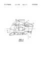
- FIG. 6Ashows a jet propulsion system made in accordance with the present invention.
- the basic structure of the first nozzle 34 and the second nozzle 36are generally the same as those illustrated in FIG. 5A, but a trim tab 60 is attached to the internal bottom surface of the second nozzle 36.
- a threaded stud 62extends from the trim tab 60 and the threaded stud is passed through a hole in the second nozzle 36.
- a nut 64is used to rigidly attach the trim tab 60 to the internal surface of the second nozzle 36.
- the trim tab 60can also be attached to the first nozzle 34, as illustrated by dashed lines in FIG. 6A. It would similarly be attached to the first nozzle 34 through the use of the threaded stud 62 and the nut 64.
- FIG. 6Bis an end view of the illustration in FIG. 6A, showing the second nozzle 36, the trim tab 60, the threaded stud 62, and a nut 64.
- the trim tab 60has two surfaces, 67, and 68. If the trim tab is rotated about the centerline of the threaded nut 62 and then rigidly attached by the nut 64, one of these two surfaces, 67 or 68, can be turned to a position against which water will impinge as it passes through the second nozzle 36. As a result, an effective thrust vector toward port or starboard can be created by exposing one of the two surfaces, 67 and 68, to the flow of water passing through the first and second nozzles.
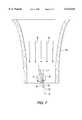
- FIG. 7is a section view of the second nozzle 36 with a plurality of arrows B representing the direction of water flow as the water is ejected through the first and second nozzles.
- Arrow Frepresents a thrust against the surface 68 of the trim tab 60 caused by the water impinging against the surface.
- An effective thrust vector Pin the port direction, is created by the water impinging against surface 68 of the trim tab 60.
- Force Pis effective as a corrective force when the second nozzle 36 is aligned with the first nozzle 34 and concentrically with horizontal axis 38. Therefore, when the steering mechanism is held in a straight ahead course direction by the operator, force P exerts a corrective thrust in the port direction on the watercraft.
- the trim tab 60can be rotated to achieve various angles between the parallel surfaces, 67 and 68, which are represented by dashed line 75, and the direction of water flow which is represented by arrows B.
- trim tab 60 in FIGS. 6A and 6Bis shown as being attached to the lower internal surface of the second nozzle 36 or, alternatively, to the lower internal surface of the first nozzle 34, it should be understood that the trim tab 60 could also be attached to the upper internal surface of either the first or second nozzle.
- the same resulting thrust vector P, described above in conjunction with FIG. 7,would result and would provide the same advantageous effect.
- the trim tab 60extends completely across the diameter of the second nozzle 36. This configuration provides increased surface area on both sides of the trim tab 60.
- FIG. 8Bshows the trim tab 60 aligned with the flow of water. However, it should be understood that in most applications, the trim tab 60 would be rotated about the centerline of the threaded stud 62 to place either of the two surfaces, 67 or 68, in a position which is non-parallel with the central axis 38 of the first nozzle 34. In the position shown in FIG. 8B, no port or starboard thrust would be provided. However, by rotating the trim tab 60 about the centerline of the threaded stud 62, a force vector in either the port or starboard directions can be created.
- FIG. 9is an isometric view of the trim tab 60 attached to a platform 90.
- Platform 90is attached to the threaded stud 62 and is rotatable about the centerline of the threaded stud.
- the present inventionprovides a means for creating a corrective force in either the port or starboard direction to, in effect, balance the total net forces on the watercraft when the steering mechanism is in a straight ahead direction.
- the trim tabcan be attached to the bottom or top internal surfaces of either the second nozzle which is rotatable or the first nozzle which is rigidly attached and stationary with respect to the watercraft.
- the trim tabcan extend partially across the diameter of the first or second nozzles, and be attached to either the bottom or top internal surfaces of the nozzles. Alternatively, the trim tab can extend completely across the diameter of the first or second nozzle.
- the present inventionprovides a simple way to correct for slight deviations in manufacture or assembly of a jet propulsion system.
- the present inventionallows existing jet propulsion systems to be quickly and easily modified to adjust for slight steering misalignments.
- the trim tab of the present inventionis also contained in the location which avoids externally protruding elements that can otherwise be dangerous.
Landscapes
- Chemical & Material Sciences (AREA)
- Engineering & Computer Science (AREA)
- Combustion & Propulsion (AREA)
- Mechanical Engineering (AREA)
- Ocean & Marine Engineering (AREA)
- Control Of Vehicle Engines Or Engines For Specific Uses (AREA)
- Exhaust Silencers (AREA)
Abstract
Description
Claims (11)
Priority Applications (1)
| Application Number | Priority Date | Filing Date | Title |
|---|---|---|---|
| US09/307,832US6113443A (en) | 1999-05-10 | 1999-05-10 | Trim tab for jet propulsion system |
Applications Claiming Priority (1)
| Application Number | Priority Date | Filing Date | Title |
|---|---|---|---|
| US09/307,832US6113443A (en) | 1999-05-10 | 1999-05-10 | Trim tab for jet propulsion system |
Publications (1)
| Publication Number | Publication Date |
|---|---|
| US6113443Atrue US6113443A (en) | 2000-09-05 |
Family
ID=23191358
Family Applications (1)
| Application Number | Title | Priority Date | Filing Date |
|---|---|---|---|
| US09/307,832Expired - Fee RelatedUS6113443A (en) | 1999-05-10 | 1999-05-10 | Trim tab for jet propulsion system |
Country Status (1)
| Country | Link |
|---|---|
| US (1) | US6113443A (en) |
Cited By (19)
| Publication number | Priority date | Publication date | Assignee | Title |
|---|---|---|---|---|
| US6383041B1 (en) | 2001-01-30 | 2002-05-07 | Peter D. Keefe | Rudder mechanism for jet propelled personal watercraft |
| WO2008025169A1 (en)* | 2006-09-01 | 2008-03-06 | Teleflex Megatech Inc | Trim and reverse systems for a jet propulsion watercraft |
| US20090264029A1 (en)* | 2006-12-22 | 2009-10-22 | Bombardier Recreational Products Inc. | Watercraft with steer-responsive reverse gate |
| US20090269996A1 (en)* | 2008-01-29 | 2009-10-29 | Bombardier Recreational Products Inc. | Reverse gate for jet propelled watercraft |
| US20090275248A1 (en)* | 2006-12-22 | 2009-11-05 | Bombardier Recreational Products Inc. | Watercraft reverse gate operation |
| US20090325431A1 (en)* | 2008-04-29 | 2009-12-31 | Bombardier Recreational Products Inc. | Method of indicating a deceleration of a watercraft |
| US20100041286A1 (en)* | 2007-12-21 | 2010-02-18 | Bombardier Recreational Products Inc. | Jet propulsion trim and reverse system |
| US7866272B2 (en) | 2000-01-07 | 2011-01-11 | Johan Ullman | Control handle for a vessel and a vessel including such a control handle |
| US20110114004A1 (en)* | 2009-10-29 | 2011-05-19 | Mark X Steering Systems, Llc | Electromechanically actuated steering vane for marine vessel |
| US9376189B1 (en) | 2012-05-24 | 2016-06-28 | Bombardier Recreational Products Inc. | Trim and reverse system for a watercraft jet propulsion system |
| HRP20120430B1 (en)* | 2012-05-18 | 2018-06-29 | Marko Zelić | Rotate tubular nozzle with movable barrier for propulsion with discontinuos high pressure gas |
| US10486786B1 (en) | 2018-08-21 | 2019-11-26 | Indmar Products Company Inc. | Jet pump |
| US11155322B2 (en) | 2018-10-01 | 2021-10-26 | Marine Canada Acquisition Inc. | Watertight electric actuator for trim tab assembly or wake gate assembly |
| US11492090B2 (en) | 2018-08-21 | 2022-11-08 | Indmar Products Company, Inc. | Jet pump |
| US12065230B1 (en) | 2022-02-15 | 2024-08-20 | Brunswick Corporation | Marine propulsion control system and method with rear and lateral marine drives |
| US12110088B1 (en) | 2022-07-20 | 2024-10-08 | Brunswick Corporation | Marine propulsion system and method with rear and lateral marine drives |
| US12122483B2 (en) | 2018-10-01 | 2024-10-22 | Dometic Marine Canada Inc. | Actuator |
| US12134454B1 (en) | 2022-07-20 | 2024-11-05 | Brunswick Corporation | Marine propulsion system and method with single rear drive and lateral marine drive |
| US12258115B2 (en) | 2022-07-20 | 2025-03-25 | Brunswick Corporation | Marine propulsion system and joystick control method |
Citations (16)
| Publication number | Priority date | Publication date | Assignee | Title |
|---|---|---|---|---|
| US3799103A (en)* | 1972-06-26 | 1974-03-26 | Outboard Marine Corp | Stern drive unit trim tab |
| US3817202A (en)* | 1973-07-05 | 1974-06-18 | Outboard Marine Corp | Anti-ventilation fence for a trim tab |
| US3906885A (en)* | 1973-11-30 | 1975-09-23 | Brunswick Corp | Marine jet drive with power trim control and auxiliary rudder steering |
| US3943876A (en)* | 1973-12-06 | 1976-03-16 | Kiekhaefer Aeromarine Motors, Inc. | Water jet boat drive |
| US3955527A (en)* | 1974-07-08 | 1976-05-11 | Outboard Marine Corporation | Marine propulsion trim tab with anti ventilation means |
| US4056073A (en)* | 1974-07-25 | 1977-11-01 | Omnithruster Inc. | Boat thruster |
| US4315749A (en)* | 1979-08-27 | 1982-02-16 | Maritec Corporation | Non jamming reversible jet nozzle |
| US4509924A (en)* | 1982-12-20 | 1985-04-09 | Outboard Marine Corporation | Control system for torque correcting device |
| US4693689A (en)* | 1983-11-30 | 1987-09-15 | Sanshin Kogyo Kabushiki Kaisha | Controlling gear for outboard engine |
| US4908766A (en)* | 1986-07-28 | 1990-03-13 | Sanshin Kogyo Kabushiki Kaisha | Trim tab actuator for marine propulsion device |
| US4917637A (en)* | 1987-05-28 | 1990-04-17 | Kawasaki Jukogyo Kabushiki Kaisha | Waterjet propulsion system for watercraft |
| JPH0321587A (en)* | 1989-06-20 | 1991-01-30 | Toshiba Corp | water jet propulsion machine |
| US5154650A (en)* | 1989-08-03 | 1992-10-13 | Sanshin Kogyo Kabushiki Kaisha | Water jet propulsion unit |
| US5277631A (en)* | 1991-10-14 | 1994-01-11 | Sanshin Kogyo Kabushiki Kaisha | Vane arrangement for a water jet propulsion assembly |
| US5752864A (en)* | 1997-01-16 | 1998-05-19 | Brunswick Corporation | Reverse gate for personal watercraft |
| US5755601A (en)* | 1997-03-17 | 1998-05-26 | Brunswick Corporation | Brake system for personal watercraft |
- 1999
- 1999-05-10USUS09/307,832patent/US6113443A/ennot_activeExpired - Fee Related
Patent Citations (16)
| Publication number | Priority date | Publication date | Assignee | Title |
|---|---|---|---|---|
| US3799103A (en)* | 1972-06-26 | 1974-03-26 | Outboard Marine Corp | Stern drive unit trim tab |
| US3817202A (en)* | 1973-07-05 | 1974-06-18 | Outboard Marine Corp | Anti-ventilation fence for a trim tab |
| US3906885A (en)* | 1973-11-30 | 1975-09-23 | Brunswick Corp | Marine jet drive with power trim control and auxiliary rudder steering |
| US3943876A (en)* | 1973-12-06 | 1976-03-16 | Kiekhaefer Aeromarine Motors, Inc. | Water jet boat drive |
| US3955527A (en)* | 1974-07-08 | 1976-05-11 | Outboard Marine Corporation | Marine propulsion trim tab with anti ventilation means |
| US4056073A (en)* | 1974-07-25 | 1977-11-01 | Omnithruster Inc. | Boat thruster |
| US4315749A (en)* | 1979-08-27 | 1982-02-16 | Maritec Corporation | Non jamming reversible jet nozzle |
| US4509924A (en)* | 1982-12-20 | 1985-04-09 | Outboard Marine Corporation | Control system for torque correcting device |
| US4693689A (en)* | 1983-11-30 | 1987-09-15 | Sanshin Kogyo Kabushiki Kaisha | Controlling gear for outboard engine |
| US4908766A (en)* | 1986-07-28 | 1990-03-13 | Sanshin Kogyo Kabushiki Kaisha | Trim tab actuator for marine propulsion device |
| US4917637A (en)* | 1987-05-28 | 1990-04-17 | Kawasaki Jukogyo Kabushiki Kaisha | Waterjet propulsion system for watercraft |
| JPH0321587A (en)* | 1989-06-20 | 1991-01-30 | Toshiba Corp | water jet propulsion machine |
| US5154650A (en)* | 1989-08-03 | 1992-10-13 | Sanshin Kogyo Kabushiki Kaisha | Water jet propulsion unit |
| US5277631A (en)* | 1991-10-14 | 1994-01-11 | Sanshin Kogyo Kabushiki Kaisha | Vane arrangement for a water jet propulsion assembly |
| US5752864A (en)* | 1997-01-16 | 1998-05-19 | Brunswick Corporation | Reverse gate for personal watercraft |
| US5755601A (en)* | 1997-03-17 | 1998-05-26 | Brunswick Corporation | Brake system for personal watercraft |
Cited By (34)
| Publication number | Priority date | Publication date | Assignee | Title |
|---|---|---|---|---|
| US7866272B2 (en) | 2000-01-07 | 2011-01-11 | Johan Ullman | Control handle for a vessel and a vessel including such a control handle |
| US6383041B1 (en) | 2001-01-30 | 2002-05-07 | Peter D. Keefe | Rudder mechanism for jet propelled personal watercraft |
| US20080182463A1 (en)* | 2006-09-01 | 2008-07-31 | Luc St-Pierre | Commonly actuated trim and reverse system for a jet propulsion watercraft |
| US20080133075A1 (en)* | 2006-09-01 | 2008-06-05 | Luc St-Pierre | Automatic trim system for a jet propulsion watercraft |
| US8000851B2 (en) | 2006-09-01 | 2011-08-16 | Teleflex Megatech Inc. | Automatic trim system for a jet propulsion watercraft |
| US8478465B2 (en) | 2006-09-01 | 2013-07-02 | Kongsberg Inc. | Electronically assisted reverse gate system for a jet propulsion watercraft |
| WO2008025169A1 (en)* | 2006-09-01 | 2008-03-06 | Teleflex Megatech Inc | Trim and reverse systems for a jet propulsion watercraft |
| US7775844B2 (en) | 2006-09-01 | 2010-08-17 | Teleflex Megatech, Inc. | Electronically assisted reverse gate system for a jet propulsion watercraft |
| US7892053B2 (en) | 2006-09-01 | 2011-02-22 | Teleflex Megatech Inc. | Commonly actuated trim and reverse system for a jet propulsion watercraft |
| US20090264029A1 (en)* | 2006-12-22 | 2009-10-22 | Bombardier Recreational Products Inc. | Watercraft with steer-responsive reverse gate |
| US8202136B2 (en) | 2006-12-22 | 2012-06-19 | Bombardier Recreational Products Inc. | Watercraft with steer-responsive reverse gate |
| US20090275248A1 (en)* | 2006-12-22 | 2009-11-05 | Bombardier Recreational Products Inc. | Watercraft reverse gate operation |
| US7708609B2 (en) | 2006-12-22 | 2010-05-04 | Bombardier Recreational Products Inc. | Watercraft reverse gate operation |
| US20100041286A1 (en)* | 2007-12-21 | 2010-02-18 | Bombardier Recreational Products Inc. | Jet propulsion trim and reverse system |
| US7841915B2 (en) | 2007-12-21 | 2010-11-30 | Bombardier Recreational Products, Inc. | Jet propulsion trim and reverse system |
| US7674144B2 (en) | 2008-01-29 | 2010-03-09 | Bombardier Recreational Products Inc. | Reverse gate for jet propelled watercraft |
| US20090269996A1 (en)* | 2008-01-29 | 2009-10-29 | Bombardier Recreational Products Inc. | Reverse gate for jet propelled watercraft |
| US7901259B2 (en) | 2008-04-29 | 2011-03-08 | Bombardier Recreational Products Inc. | Method of indicating a deceleration of a watercraft |
| US20090325431A1 (en)* | 2008-04-29 | 2009-12-31 | Bombardier Recreational Products Inc. | Method of indicating a deceleration of a watercraft |
| US20110114004A1 (en)* | 2009-10-29 | 2011-05-19 | Mark X Steering Systems, Llc | Electromechanically actuated steering vane for marine vessel |
| US8376794B2 (en) | 2009-10-29 | 2013-02-19 | Mark X Steering Systems, Llc | Electromechanically actuated steering vane for marine vessel |
| HRP20120430B1 (en)* | 2012-05-18 | 2018-06-29 | Marko Zelić | Rotate tubular nozzle with movable barrier for propulsion with discontinuos high pressure gas |
| US9376189B1 (en) | 2012-05-24 | 2016-06-28 | Bombardier Recreational Products Inc. | Trim and reverse system for a watercraft jet propulsion system |
| US11492090B2 (en) | 2018-08-21 | 2022-11-08 | Indmar Products Company, Inc. | Jet pump |
| US10486786B1 (en) | 2018-08-21 | 2019-11-26 | Indmar Products Company Inc. | Jet pump |
| US10787237B2 (en) | 2018-08-21 | 2020-09-29 | Indmar Products Company, Inc. | Jet pump |
| US10933965B2 (en) | 2018-08-21 | 2021-03-02 | Indmar Products Company Inc. | Method of installing jet pump |
| US11319045B2 (en) | 2018-08-21 | 2022-05-03 | Indmar Products Company, Inc. | Jet pump |
| US11155322B2 (en) | 2018-10-01 | 2021-10-26 | Marine Canada Acquisition Inc. | Watertight electric actuator for trim tab assembly or wake gate assembly |
| US12122483B2 (en) | 2018-10-01 | 2024-10-22 | Dometic Marine Canada Inc. | Actuator |
| US12065230B1 (en) | 2022-02-15 | 2024-08-20 | Brunswick Corporation | Marine propulsion control system and method with rear and lateral marine drives |
| US12110088B1 (en) | 2022-07-20 | 2024-10-08 | Brunswick Corporation | Marine propulsion system and method with rear and lateral marine drives |
| US12134454B1 (en) | 2022-07-20 | 2024-11-05 | Brunswick Corporation | Marine propulsion system and method with single rear drive and lateral marine drive |
| US12258115B2 (en) | 2022-07-20 | 2025-03-25 | Brunswick Corporation | Marine propulsion system and joystick control method |
Similar Documents
| Publication | Publication Date | Title |
|---|---|---|
| US6113443A (en) | Trim tab for jet propulsion system | |
| US5755601A (en) | Brake system for personal watercraft | |
| US5752864A (en) | Reverse gate for personal watercraft | |
| US7018252B2 (en) | Watercraft control mechanism | |
| US5540174A (en) | Trim adjusting system for jet propulsion boat | |
| US6142841A (en) | Waterjet docking control system for a marine vessel | |
| US5421753A (en) | Marine jet drive | |
| US6523489B2 (en) | Personal watercraft and off-power steering system for a personal watercraft | |
| US5720636A (en) | Marine propulsor | |
| US4538997A (en) | Reversing means in water-jet propulsion units | |
| US6227919B1 (en) | Water jet propulsion unit with means for providing lateral thrust | |
| US5582125A (en) | Small jet propelled boat | |
| US5934954A (en) | Braking system for a watercraft | |
| US6004173A (en) | Marine propulsion system with bypass eductor | |
| US11046406B1 (en) | Watercraft and venturi unit | |
| US4073257A (en) | Marine propulsion system | |
| US6722932B2 (en) | Braking device for watercraft | |
| US6776676B2 (en) | Personal watercraft | |
| NZ195791A (en) | Steering mechanism for marine jet propulsion unit | |
| US6675730B2 (en) | Personal watercraft having off-power steering system | |
| US7217165B2 (en) | Waterjet steering and reversing apparatus | |
| US3078661A (en) | Bow steering for hydraulic jetdriven boat | |
| US7101235B2 (en) | Air-boat sound suppressor and directional control system | |
| US6024614A (en) | High performance marine propulsion system | |
| US6102756A (en) | Turning-aid nozzle |
Legal Events
| Date | Code | Title | Description |
|---|---|---|---|
| AS | Assignment | Owner name:BRUNSWICK CORPORATION, WISCONSIN Free format text:ASSIGNMENT OF ASSIGNORS INTEREST;ASSIGNOR:EICHINGER, CHARLES H.;REEL/FRAME:009966/0567 Effective date:19990507 | |
| FPAY | Fee payment | Year of fee payment:4 | |
| FPAY | Fee payment | Year of fee payment:8 | |
| AS | Assignment | Owner name:JPMORGAN CHASE BANK, N.A., TEXAS Free format text:SECURITY AGREEMENT;ASSIGNORS:BRUNSWICK CORPORATION;TRITON BOAT COMPANY, L.P.;ATTWOOD CORPORATION;AND OTHERS;REEL/FRAME:022092/0365 Effective date:20081219 Owner name:JPMORGAN CHASE BANK, N.A.,TEXAS Free format text:SECURITY AGREEMENT;ASSIGNORS:BRUNSWICK CORPORATION;TRITON BOAT COMPANY, L.P.;ATTWOOD CORPORATION;AND OTHERS;REEL/FRAME:022092/0365 Effective date:20081219 | |
| AS | Assignment | Owner name:THE BANK OF NEW YORK MELLON TRUST COMPANY, N.A., I Free format text:SECURITY AGREEMENT;ASSIGNORS:BRUNSWICK CORPORATION;ATTWOOD CORPORATION;BOSTON WHALER, INC.;AND OTHERS;REEL/FRAME:023180/0493 Effective date:20090814 Owner name:THE BANK OF NEW YORK MELLON TRUST COMPANY, N.A.,IL Free format text:SECURITY AGREEMENT;ASSIGNORS:BRUNSWICK CORPORATION;ATTWOOD CORPORATION;BOSTON WHALER, INC.;AND OTHERS;REEL/FRAME:023180/0493 Effective date:20090814 | |
| AS | Assignment | Owner name:LAND 'N' SEA DISTRIBUTING, INC., FLORIDA Free format text:RELEASE BY SECURED PARTY;ASSIGNOR:JPMORGAN CHASE BANK, N.A., AS ADMINISTRATIVE AGENT;REEL/FRAME:026026/0001 Effective date:20110321 Owner name:ATTWOOD CORPORATION, MICHIGAN Free format text:RELEASE BY SECURED PARTY;ASSIGNOR:JPMORGAN CHASE BANK, N.A., AS ADMINISTRATIVE AGENT;REEL/FRAME:026026/0001 Effective date:20110321 Owner name:TRITON BOAT COMPANY, L.P., TENNESSEE Free format text:RELEASE BY SECURED PARTY;ASSIGNOR:JPMORGAN CHASE BANK, N.A., AS ADMINISTRATIVE AGENT;REEL/FRAME:026026/0001 Effective date:20110321 Owner name:BRUNSWICK BOWLING & BILLIARDS CORPORATION, ILLINOI Free format text:RELEASE BY SECURED PARTY;ASSIGNOR:JPMORGAN CHASE BANK, N.A., AS ADMINISTRATIVE AGENT;REEL/FRAME:026026/0001 Effective date:20110321 Owner name:BRUNSWICK LEISURE BOAT COMPANY, LLC, INDIANA Free format text:RELEASE BY SECURED PARTY;ASSIGNOR:JPMORGAN CHASE BANK, N.A., AS ADMINISTRATIVE AGENT;REEL/FRAME:026026/0001 Effective date:20110321 Owner name:BRUNSWICK FAMILY BOAT CO. INC., WASHINGTON Free format text:RELEASE BY SECURED PARTY;ASSIGNOR:JPMORGAN CHASE BANK, N.A., AS ADMINISTRATIVE AGENT;REEL/FRAME:026026/0001 Effective date:20110321 Owner name:BOSTON WHALER, INC., FLORIDA Free format text:RELEASE BY SECURED PARTY;ASSIGNOR:JPMORGAN CHASE BANK, N.A., AS ADMINISTRATIVE AGENT;REEL/FRAME:026026/0001 Effective date:20110321 Owner name:BRUNSWICK CORPORATION, ILLINOIS Free format text:RELEASE BY SECURED PARTY;ASSIGNOR:JPMORGAN CHASE BANK, N.A., AS ADMINISTRATIVE AGENT;REEL/FRAME:026026/0001 Effective date:20110321 Owner name:BRUNSWICK COMMERICAL & GOVERNMENT PRODUCTS, INC., Free format text:RELEASE BY SECURED PARTY;ASSIGNOR:JPMORGAN CHASE BANK, N.A., AS ADMINISTRATIVE AGENT;REEL/FRAME:026026/0001 Effective date:20110321 Owner name:LUND BOAT COMPANY, MINNESOTA Free format text:RELEASE BY SECURED PARTY;ASSIGNOR:JPMORGAN CHASE BANK, N.A., AS ADMINISTRATIVE AGENT;REEL/FRAME:026026/0001 Effective date:20110321 | |
| AS | Assignment | Owner name:JPMORGAN CHASE BANK, N.A., AS ADMINISTRATIVE AGENT Free format text:SECURITY AGREEMENT;ASSIGNORS:BRUNSWICK CORPORATION;ATTWOOD CORPORATION;BOSTON WHALER, INC.;AND OTHERS;REEL/FRAME:026072/0239 Effective date:20110321 | |
| REMI | Maintenance fee reminder mailed | ||
| LAPS | Lapse for failure to pay maintenance fees | ||
| STCH | Information on status: patent discontinuation | Free format text:PATENT EXPIRED DUE TO NONPAYMENT OF MAINTENANCE FEES UNDER 37 CFR 1.362 | |
| FP | Lapsed due to failure to pay maintenance fee | Effective date:20120905 | |
| AS | Assignment | Owner name:BRUNSWICK CORPORATION, ILLINOIS Free format text:RELEASE BY SECURED PARTY;ASSIGNOR:THE BANK OF NEW YORK MELLON;REEL/FRAME:031973/0242 Effective date:20130717 | |
| AS | Assignment | Owner name:LAND 'N' SEA DISTRIBUTING, INC., ILLINOIS Free format text:RELEASE BY SECURED PARTY;ASSIGNOR:JPMORGAN CHASE BANK, N.A.;REEL/FRAME:034794/0300 Effective date:20141226 Owner name:BOSTON WHALER, INC., ILLINOIS Free format text:RELEASE BY SECURED PARTY;ASSIGNOR:JPMORGAN CHASE BANK, N.A.;REEL/FRAME:034794/0300 Effective date:20141226 Owner name:BRUNSWICK FAMILY BOAT CO. INC., ILLINOIS Free format text:RELEASE BY SECURED PARTY;ASSIGNOR:JPMORGAN CHASE BANK, N.A.;REEL/FRAME:034794/0300 Effective date:20141226 Owner name:ATTWOOD CORPORATION, ILLINOIS Free format text:RELEASE BY SECURED PARTY;ASSIGNOR:JPMORGAN CHASE BANK, N.A.;REEL/FRAME:034794/0300 Effective date:20141226 Owner name:BRUNSWICK CORPORATION, ILLINOIS Free format text:RELEASE BY SECURED PARTY;ASSIGNOR:JPMORGAN CHASE BANK, N.A.;REEL/FRAME:034794/0300 Effective date:20141226 Owner name:BRUNSWICK BOWLING & BILLIARDS CORPORATION, ILLINOI Free format text:RELEASE BY SECURED PARTY;ASSIGNOR:JPMORGAN CHASE BANK, N.A.;REEL/FRAME:034794/0300 Effective date:20141226 Owner name:BRUNSWICK COMMERCIAL & GOVERNMENT PRODUCTS, INC., Free format text:RELEASE BY SECURED PARTY;ASSIGNOR:JPMORGAN CHASE BANK, N.A.;REEL/FRAME:034794/0300 Effective date:20141226 Owner name:LUND BOAT COMPANY, ILLINOIS Free format text:RELEASE BY SECURED PARTY;ASSIGNOR:JPMORGAN CHASE BANK, N.A.;REEL/FRAME:034794/0300 Effective date:20141226 Owner name:BRUNSWICK LEISURE BOAT COMPANY, LLC, ILLINOIS Free format text:RELEASE BY SECURED PARTY;ASSIGNOR:JPMORGAN CHASE BANK, N.A.;REEL/FRAME:034794/0300 Effective date:20141226 |