US6113265A - C-arm apparatus with improved C-arm locking mechanism - Google Patents
C-arm apparatus with improved C-arm locking mechanismDownload PDFInfo
- Publication number
- US6113265A US6113265AUS09/199,952US19995298AUS6113265AUS 6113265 AUS6113265 AUS 6113265AUS 19995298 AUS19995298 AUS 19995298AUS 6113265 AUS6113265 AUS 6113265A
- Authority
- US
- United States
- Prior art keywords
- track
- shoe
- handle
- driver
- arm
- Prior art date
- Legal status (The legal status is an assumption and is not a legal conclusion. Google has not performed a legal analysis and makes no representation as to the accuracy of the status listed.)
- Expired - Lifetime
Links
- 230000007246mechanismEffects0.000titleabstractdescription32
- 238000003384imaging methodMethods0.000claimsabstractdescription9
- 238000007373indentationMethods0.000claimsdescription21
- 210000003414extremityAnatomy0.000description13
- 230000006835compressionEffects0.000description6
- 238000007906compressionMethods0.000description6
- 238000000034methodMethods0.000description5
- 210000000988bone and boneAnatomy0.000description3
- 230000003247decreasing effectEffects0.000description2
- 229910052500inorganic mineralInorganic materials0.000description2
- 239000011707mineralSubstances0.000description2
- 239000007787solidSubstances0.000description2
- JOYRKODLDBILNP-UHFFFAOYSA-NEthyl urethaneChemical compoundCCOC(N)=OJOYRKODLDBILNP-UHFFFAOYSA-N0.000description1
- 210000003423ankleAnatomy0.000description1
- 238000001739density measurementMethods0.000description1
- 238000006073displacement reactionMethods0.000description1
- 230000009977dual effectEffects0.000description1
- 210000002683footAnatomy0.000description1
- 230000036512infertilityEffects0.000description1
- 230000014759maintenance of locationEffects0.000description1
- 239000002184metalSubstances0.000description1
- 230000000087stabilizing effectEffects0.000description1
- 210000000707wristAnatomy0.000description1
Images


Classifications
- A—HUMAN NECESSITIES
- A61—MEDICAL OR VETERINARY SCIENCE; HYGIENE
- A61B—DIAGNOSIS; SURGERY; IDENTIFICATION
- A61B6/00—Apparatus or devices for radiation diagnosis; Apparatus or devices for radiation diagnosis combined with radiation therapy equipment
- A61B6/44—Constructional features of apparatus for radiation diagnosis
- A61B6/4429—Constructional features of apparatus for radiation diagnosis related to the mounting of source units and detector units
- A61B6/4435—Constructional features of apparatus for radiation diagnosis related to the mounting of source units and detector units the source unit and the detector unit being coupled by a rigid structure
- A61B6/4441—Constructional features of apparatus for radiation diagnosis related to the mounting of source units and detector units the source unit and the detector unit being coupled by a rigid structure the rigid structure being a C-arm or U-arm
- A—HUMAN NECESSITIES
- A61—MEDICAL OR VETERINARY SCIENCE; HYGIENE
- A61B—DIAGNOSIS; SURGERY; IDENTIFICATION
- A61B6/00—Apparatus or devices for radiation diagnosis; Apparatus or devices for radiation diagnosis combined with radiation therapy equipment
- A61B6/10—Safety means specially adapted therefor
- A61B6/102—Protection against mechanical damage, e.g. anti-collision devices
- A61B6/105—Braking or locking devices
- A—HUMAN NECESSITIES
- A61—MEDICAL OR VETERINARY SCIENCE; HYGIENE
- A61B—DIAGNOSIS; SURGERY; IDENTIFICATION
- A61B6/00—Apparatus or devices for radiation diagnosis; Apparatus or devices for radiation diagnosis combined with radiation therapy equipment
- A61B6/44—Constructional features of apparatus for radiation diagnosis
- A61B6/4405—Constructional features of apparatus for radiation diagnosis the apparatus being movable or portable, e.g. handheld or mounted on a trolley
- A—HUMAN NECESSITIES
- A61—MEDICAL OR VETERINARY SCIENCE; HYGIENE
- A61B—DIAGNOSIS; SURGERY; IDENTIFICATION
- A61B6/00—Apparatus or devices for radiation diagnosis; Apparatus or devices for radiation diagnosis combined with radiation therapy equipment
- A61B6/44—Constructional features of apparatus for radiation diagnosis
- A61B6/4423—Constructional features of apparatus for radiation diagnosis related to hygiene or sterilisation
Definitions
- This inventionrelates to C-arm apparatus and, in an important aspect, to mini C-arm systems such as are used for fluoroscopic imaging of a human patient's extremities and for other medical diagnostic purposes. More particularly, the invention relates to mini C-arm imaging apparatus incorporating new and improved locking mechanisms for holding the C-arm stationary in a selected position relative to C-arm supporting structure.
- Mini C-arm imaging systemsare well known and widely used in present-day medical practice, e.g. to provide fluoroscopic images and/or bone mineral density measurements of a human patient's extremity such as a wrist, hand, ankle or foot.
- One example of such mini C-arm apparatusis described in copending allowed U.S. patent application Ser. No. 08/794,615 filed Feb. 3, 1997 (in which the issue fee has been paid), the entire disclosure of which is incorporated herein by this reference.
- Another exampleis the apparatus described in U.S. Pat. No. 5,627,873, the entire disclosure of which is also incorporated herein by this reference.
- a mini C-arm system of the type herein contemplatedincludes a rigid C-shaped track continuously curved along an arc of a circle, with two opposed ends spaced apart by a gap and respectively carrying an x-ray source and an x-ray detector that face each other across the gap so that x-rays emitted by the source are incident on and detected by the detector.
- the source and detectorare so arranged that when an object such as a human extremity is interposed in the gap and irradiated with x-rays from the source, the detector produces data representative of characteristics of the interposed object.
- the produced datamay be displayed on a CRT as a fluoroscopic image of the object, or may be used (as the aforementioned allowed application Ser. No. 08/794,615 describes) to measure bone mineral density (BMD) of bone in the extremity.
- BMDbone mineral density
- the C-arm trackis slidably mounted in a support member so as to be movable, relative to the support member, along a circular path substantially coincident (i.e. concentric) with the arc of curvature of the track.
- the support memberis pivoted on the distal end of an arm (or, preferably, an articulated arm assembly including two or more sections movable relative to each other) having a proximal end pivotally secured to a base.
- the various interconnections, pivots and articulationspermit relatively easy movement, to facilitate positioning of the source and detector by a user such as a physician.
- a usersuch as a physician.
- the mini C-arm trackmay be mass balanced about the center of curvature of the track to aid in stabilizing the C-arm at any desired position relative to the support member, although this mass balancing does not obviate the provision of locking means.
- Locking means heretofore used to hold the C-arm track fixed in relation to the support memberhave typically been screw mechanisms carried by the support member for bearing frictionally, when tightened, against a surface of the curved track.
- An object of the inventionis to provide, in C-arm apparatus such as the mini C-arm x-ray systems discussed above, new and improved mechanism for locking the C-arm track in a selected position of its orbital rotation about its center of curvature relative to a supporting member in which the track slides. Further, specific objects are to provide such a mechanism affording a plurality of different, easily settable degrees of drag on the track, and to provide such a mechanism having improved security against accidental dislodgment as by the pulling force of a moving surgical drape.
- the present inventionis embodied in C-arm apparatus including a rigid C-shaped track having a circular arc of curvature and opposed free ends, spaced apart by a gap, for respectively bearing two elements which are to be maintained in fixed relation to each other and to be adjustably positionable in relation to an object which is to be disposed in the gap, the track having a surface extending along its length; and a member supporting the track for longitudinal guided sliding movement along an arcuate path coincident with the arc of curvature of the track to orbit the elements.
- the inventionbroadly contemplates the provision, in such apparatus, of locking mechanism comprising, in combination, a brake shoe for bearing against the track surface; a driver, mounted in the supporting member and carrying the brake shoe, for moving the brake shoe toward and away from the track surface through a range of positions between a first position in which the shoe bears against the track surface with full braking force to prevent movement of the track along the path and a second position in which the shoe exerts substantially no braking force on the surface, the shoe being resiliently compressible toward the driver so that as the shoe moves progressively through at least a substantial part of its range of positions, it exerts a progressively varying force on the track surface; a handle connected to the driver for operating the driver to move the shoe through the aforesaid range of positions; and a detent cooperating with the handle to releasably arrest the handle in each of a plurality, greater than two, of locations respectively corresponding to a like plurality of positions of the shoe, within the range of shoe positions, including the
- the apparatusin convenient and currently preferred embodiments thereof, includes a resilient bias-exerting device (e.g. a spring) acting between the shoe and the driver so that the shoe is resiliently compressible toward the driver as aforesaid, the bias exerted by this device urging the shoe away from the driver to a limited extent such that when the shoe is in the second position it does not engage the track surface.
- a resilient bias-exerting devicee.g. a spring acting between the shoe and the driver so that the shoe is resiliently compressible toward the driver as aforesaid, the bias exerted by this device urging the shoe away from the driver to a limited extent such that when the shoe is in the second position it does not engage the track surface.
- the drivercomprises a screw connected to the brake shoe and a nut carried by the supporting member, the screw being threaded in the nut whereby the screw and nut have a common thread axis, the handle being connected to one of the screw and nut for rotation therewith about the thread axis, and the other of the screw and nut being held against rotation about the thread axis.
- the handlemay be keyed to the screw so that the screw and handle rotate together while the screw has a limited range of axial movement relative to the handle, and the nut may be fixedly mounted in the supporting member.
- the handlehas a surface, facing a portion of the supporting member, formed with a plurality of indentations corresponding in number to the aforesaid plurality of handle locations, and the detent comprises a spring-loaded body having a convexly rounded surface, mounted in the last-mentioned portion of the supporting member so as to be sequentially receivable in the handle indentations to arrest the handle at each of the plurality of locations.
- the screwmay be formed with a central cylindrical recess having a geometric axis and an open end facing the track surface, the brake shoe being received within the recess and axially movable therein; and a resiliently compressible spring may be disposed within the recess to act between the screw and the brake shoe, urging the brake shoe toward the track surface.
- the locking mechanismmay include a second brake shoe for bearing against that second surface, and a second driver, mounted in the supporting member and carrying the second brake shoe, for moving the second brake shoe toward and away from the second track surface through the aforesaid range of positions, the second shoe being resiliently compressible toward the second driver such that as the second shoe moves progressively through at least a substantial part of its range it exerts a progressively varying force on the second track surface, the handle being connected to the second driver (as well as to the first driver) for operating the second driver to move the second brake shoe through the range of positions as the first shoe moves through the range of positions, the first and second shoes cooperating to exert braking force simultaneously against both the first-mentioned surface and the second surface of the track.
- the two elements carried by the trackare, respectively, an x-ray source and an x-ray detector that face each other across the gap so that x-rays emitted by the source are incident on and detected by the detector, the source and detector being so arranged that when an object such as a human extremity is interposed in the gap and irradiated with x-rays from the source, the detector produces data representative of characteristics of the interposed object.
- the inventioncontemplates the provision of the foregoing features, including the described locking mechanism, in a mini C-arm fluoroscopic imaging system, which includes an arm assembly having a proximal end and a distal end, the supporting member being pivotally mounted on the distal end of the assembly for rotation relative thereto about a first axis; and a base to which the proximal end of the arm assembly is pivotally mounted for rotation about a second axis different from the first axis.
- the present inventionachieves the aforementioned objects, in particular, through the combination of the resilient bias or resilient compressibility of the mounting of the brake shoe or shoes and the multiple-setting detent mechanism wherein the different settings correspond to respectively different positions of the shoe or shoes. That is to say, owing to the resilient bias, such different shoe positions respectively provide incrementally different forces exerted by the shoe against the track, enabling the physician operating the C-arm equipment to readily select a desired degree of drag simply by moving the handle to the appropriate detent setting. Such a procedure is easier and more certain than attempting to adjust the degree of force exerted by a simple, continuously turnable screw-type braking mechanism.
- the detentalso resists dislodgement of the brake shoe more surely than a simple screw-type mechanism, especially in situations where the screw has been delicately manipulated to some light or intermediate-drag position.
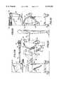
- FIG. 1is a simplified and partly schematic side elevational view of mini C-arm x-ray fluoroscopic imaging apparatus incorporating an illustrative embodiment of the present invention
- FIGS. 2A, 2B, 2C and 2Dare reduced-scale views of the apparatus of FIG. 1, respectively in side elevation with the arm assembly extended (showing different positions thereof), in plan with the arm assembly extended, in side elevation with the arm assembly folded, and in plan with the arm assembly folded.
- FIGS. 3A, 3B, 3C and 3Dare enlarged views of a portion of FIG. 1, respectively in side elevation, top plan, fragmentary bottom plan, and front elevation;
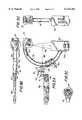
- FIG. 4is a further enlarged side elevational view of the supporting member and locking mechanism of the embodiment of FIG. 1, showing a fragmentary portion of the C-shaped track;
- FIGS. 5A and 5Bare views similar to FIG. 4 but somewhat reduced in scale and respectively showing the positions of the C-shaped track adjacent the lower and upper limits of its sliding movement relative to the supporting member;
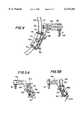
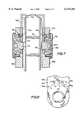
- FIG. 6is a still further enlarged, schematic sectional view of the locking mechanism and associated structures of the embodiment illustrated in FIG. 4;
- FIG. 7is a view similar to FIG. 6 of a somewhat modified embodiment of the invention.
- FIG. 8is a fragmentary elevational view of the handle of the locking mechanism of the embodiment of FIG. 6;
- FIGS. 9A and 9Bare, respectively, sectional elevational and plan views of the driver nut in the locking mechanism of FIG. 6;
- FIGS. 10A and 10Bare, respectively, elevational sectional and plan views of the driver screw in the locking mechanism of FIG. 6;
- FIGS. 11A and 11Bare, respectively, side and front elevational views of a side plate of the guide structure of the supporting member in the embodiment of FIG. 4;
- FIGS. 12A and 12Bare, respectively, side and front elevational views of the main body of the supporting member in the embodiment of FIG. 4.
- FIG. 1a mini C-arm x-ray fluoroscopic imaging system 10 (FIG. 1) which is entirely contained in a wheeled cart or cabinet 11 that can easily be rolled from place to place.
- the cabinetincludes a generally rectangular, upright body 12 that supports one or dual video monitors 14 (only one being shown) on its top surface and has, in its upper portion, an articulated arm assembly 18; the cabinet also contains a computer (not shown) for processing data.
- the outer end of the articulated arm assembly 18carries a mini C-arm 20 having an x-ray source 22 and a detector 24 respectively fixedly mounted at its opposite extremities so that an x-ray beam 26 from source 22 impinges on the input end 28 of the detector, the source and detector being spaced apart by the C-arm sufficiently to define a gap 29 between them, in which the limb or extremity of a human patient 30 can be inserted in the path of the x-ray beam 26.
- the mounting of the C-arm and associated portion of assembly 18, as hereinafter further described,is such as to enable the C-arm to be swivelled or rotated about each of three different axes and to be held stably at any desired position, while the arm assembly 18 is itself mounted and jointed to enable its outer end and the C-arm to be angularly displaced both horizontally and vertically.
- the multidirectional angular movability of the mini C-armfacilitates the positioning of the source and detector in relation to a patient body portion to be irradiated.
- the beam 26 emitted by the x-ray source 22is a cone-shaped beam that impinges on a flat x-ray-sensitive receiving surface of the detector 24 at or adjacent to the detector input end; the detector, which may be of a known type, produces output data signals including, for example, image data with respect to a patient's extremity interposed between the source and detector.
- the output data from the detectorare transmitted to and processed by the onboard computer, for example to produce video images on one or both monitors 14; mini C-arm x-ray systems embodying the invention may, of course, also or alternatively operate to provide other representations or manipulations of the data.
- the system 10is essentially similar to currently available mini C-arm x-ray fluoroscopic imaging systems such as those shown in the aforementioned allowed application and patent, to which reference may be made for further exemplification of details of structure and operation thereof.
- the structure of the C-arm 20includes a rigid C-shaped track 32 of hollow, rectangular cross-section, continuously curved along an arc of a circle, with opposed parallel planar longitudinal side surfaces 32a and 32b extending lengthwise, and two opposed ends 32c and 32d spaced apart by a gap and respectively carrying the x-ray source 22 and x-ray detector 24.
- a support member 34slidably mounts the C-shaped track 32 for sliding rotary movement of the track, relative to the support member, along a circular path coincident with the arc of curvature of the track, so that the x-ray source and detector can be moved rotatably (orbited) together about an axis 36 coincident with the center of circular curvature of the C-arm track and perpendicular to the plane containing the arc of curvature of the track.
- the arm assembly 18which comprises a succession of arms 18a, 18b and 18c, pivotally connected to each other end-to-end, has a proximal or inner end 18d pivotally connected to the wheeled cabinet 11 and a distal or outer end 18e. As best seen in FIG. 2A, this arm assembly permits vertical as well as pivotal positioning of the C-arm.
- the support member 34is pivotally mounted on the distal end 18e of the arm assembly (i.e., on the distal end of arm 18c) as indicated at 37 for rotation, relative thereto, about a horizontal axis 38 perpendicular to the axis 36 of sliding rotation of the C-shaped track 32 relative to the support member.
- a locking mechanism 40is provided on arm 18c to lock the pivotal mounting 37 in any desired angular position. Also, the arm 18c is pivotally secured at its proximal end, as indicated at 41, to the distal end of the arm 18b for rotary movement relative thereto about a vertical axis 42, and a locking mechanism 44 is provided for pivotal mounting 41.
- the support member 34includes a cast metal body 46 (FIGS. 12A and B) that extends downwardly (as seen, e.g., in FIG. 4) from the pivotal mounting 37 with an outward curvature conforming to the curvature of the C-shaped track 32.
- a guide structure 48elongated in the direction of the curved path of movement of the track 32 relative to the support member, and constituted of two generally planar side plates 48a (FIGS. 11A and B) and 48b secured together in parallel, spaced-apart relation to define, between them, a passage through which the C-shaped track extends, with its two longitudinal side surfaces 32a and 32b respectively facing the inner surfaces of the two side plates.
- rollers 50 mounted within the guide structureengage the track 32 to provide smooth, guided sliding movement of the track along its arcuate track.
- the support member 34 including the body 46 and guide structure 48constitutes the mounting and support for the C-shaped track (bearing the x-ray source and detector at its opposite ends) in the mini C-arm system of FIG. 1.
- FIGS. 5A and Bshow the C-shaped track at its extreme lower and upper positions within its curved path of longitudinal (orbital) movement about axis 36.
- its upper end 32c(bearing the x-ray source, not shown in FIG. 5A) is closely adjacent the guide structure 48, being just above the guide structure in the view of FIG. 5A;
- its lower end 32d(bearing the detector, not shown in FIG. 5B) is closely adjacent the guide structure 48, being just below the guide structure in the view of FIG. 5B.
- the locking mechanism 54 of the present inventionin its illustrated embodiment, is carried on the guide structure 48 and serves to arrest the track 32, with any of a plurality of incrementally different degrees of drag, at any desired position in its arcuate path at or between the end points illustrated in FIGS. 5A and B. As best seen in FIG.
- this locking mechanismbroadly comprises a brake shoe 56 for bearing against the track surface 32a, and a driver 58, mounted in the side plate 48a of the guide structure 48 of the support member 54 and carrying the brake shoe 56, for moving the brake shoe toward and away from the track surface 32a through a range of positions between a first position in which the shoe bears against the track surface with full braking force to prevent movement of the track along the path and a second position in which the shoe exerts substantially no braking force on the surface.
- the shoe 56is resiliently compressible, as hereinafter explained, toward the driver 58 so that as the shoe moves progressively through at least a substantial part of its aforesaid range of positions it exerts a progressively varying force on the track surface.
- the locking mechanismincludes a handle 60 connected to the driver 58 for operating the driver to move the shoe through its range of positions, and a detent 62 cooperating with the handle to releasably arrest the handle in each of a plurality of locations (five, in the illustrated embodiment, as indicated in FIG. 8) respectively corresponding to a like plurality of positions of the brake shoe, within the range of shoe positions, including the aforementioned first and second positions.
- Resilient compressibility of the brake shoeis provided, in this embodiment, by a resilient bias-exerting device shown as a helical spring 64 (under compression) acting between the shoe 56 and the driver 58, the bias exerted by device 64 urging the shoe away from the driver to a limited extent such that when the shoe is in its aforementioned second position, the shoe does not engage the track surface 32a.
- a resilient bias-exerting deviceshown as a helical spring 64 (under compression) acting between the shoe 56 and the driver 58, the bias exerted by device 64 urging the shoe away from the driver to a limited extent such that when the shoe is in its aforementioned second position, the shoe does not engage the track surface 32a.
- the driver 58comprises a screw 66 (FIGS. 10A and B) connected to the brake shoe 56 and a nut 68 (FIGS. 9A and B) carried by the side plate 48a of the guide structure of the support member 34, the screw being threaded in the nut whereby the screw and nut have a common thread axis.
- the handle 60is connected to one of these two elements (screw and nut) for rotation therewith about the thread axis, and the other of the screw and nut is held against rotation about the thread axis.
- the handleis connected to the screw 36 by a key engagement portion 70 (FIG.
- the handle 60has a surface 60a, facing the side plate 48a, formed with a plurality of indentations 74a, 74b, 74c, 74d and 74e, corresponding in number to the plurality of locations at which the handle can be arrested by the detent, five such indentations (and locations) being provided in the embodiment shown.
- the detent 62comprises a spring-loaded body having a convexly rounded surface, shown as a solid ball 76 urged toward the handle by a helical spring 80 under compression, mounted in the side plate 48a so as to be sequentially receivable in the indentations 74a . . . 74e to arrest the handle at each of the aforesaid plurality of locations, as the handle is rotated manually by the user about the thread axis of the driver screw and nut, turning the screw with it.
- the screw 66(FIGS. 10A and B) is formed with a central cylindrical recess 66a having a geometric axis and an open end facing the track surface 32a.
- the brake shoe 56is received within this recess and is axially movable therein; it is at present preferred that the brake shoe 56 be a solid cylindrical body fabricated of urethane "70A.”
- the bias-exerting devicein the form of the resiliently compressible spring 64, is disposed within the recess 66a, acting between the screw 66 and the brake shoe 56, to urge the brake shoe toward the track surface 32a.
- a dished cylindrical cap 82may be fitted over the exposed outer surface of the locking mechanism on the side plate 48a.
- the locking mechanismfurther includes a second brake shoe 156 (identical to shoe 56) for bearing against the second surface 32b of the track, and a second driver 158 (comprising a recess-defining screw 166 and nut 168, threaded oppositely to screw 66 and nut 68), mounted in the side plate 48b and carrying the second brake shoe, for moving the second brake shoe toward and away from the second track surface 32b through the aforesaid range of positions as the first brake shoe 56 is moved toward and away from the first track surface 32a.
- a second brake shoe 156identical to shoe 56
- a second driver 158comprising a recess-defining screw 166 and nut 168, threaded oppositely to screw 66 and nut 68
- the second shoe 156is made resiliently compressible toward the second driver by to the provision of a spring 164 within the recess of screw 166 and corresponding positionally and functionally to spring 64 described above) such that as the second shoe moves progressively through at least a substantial part of the range of shoe positions, it exerts a progressively varying force on the second track surface.
- the handle 60is formed as a yoke or U-shaped member extending over but (throughout its angular range of movement) outwardly and thus clear of the path of movement of the track 32, being connected to the screw 166 of the second driver for operating the second driver to move the second brake shoe 156 toward and away from the track as the first shoe moves through its range of positions.
- a second detent 162 and a cooperating set of recesses 174a, etc., in the side of the handle adjacent side plate 48bmay be provided to enhance the security with which the handle is arrested at each of its five (or other predetermined number of) detent positions.
- One or both of the side plates 48a and 48bmay have a V-shaped recess 48c (FIGS. 11A and B) formed in its inwardly-facing surface to define the range of movement of the handle 60 and to provide stop edges interferingly engaging the edge of the handle at its limits of travel.
- position 74ais the fully-locked position at which maximum braking force is exerted by the shoes 56 and 156 against the track 32 to hold the track fixedly against sliding movement in either direction;
- position 74e at the other end of the array of detent recesses in the handle surfaceis the free position at which the brake shoes exert no force on the track and the track is free to slide in the guide structure;
- positions 74b, 74c and 74dare intermediate brake positions (hard to soft) at which incrementally decreasing degrees of drag are exerted by the brake shoes on the track.
- the operatore.g.
- the physician using the mini C-arm x-ray systemmanually moves the handle to a desired one of these positions, for example to a light-braking position to tentatively hold the x-ray source and detector at a first chosen location in their orbital path while she or he evaluates that location, then pulls the C-arm along its track by manual force against the light drag for fine positional adjustment, and finally moves the handle to the fully locked position to secure the source and detector for use to examine a patient's extremity.
- turning of the handle 60turns the screws 66 and 166 threaded within nuts 68 and 168 and, since the nuts are fixedly secured to the side plates 48a and 48b, causes the screws to move axially toward or away from the facing surfaces 32a, 32b of the C-shaped track 32 disposed between the shoes. Whether the shoes move toward or away from the track is determined by the direction in which the handle is turned, the two screws and their associated nuts on opposite sides of the track being oppositely threaded, as mentioned above, so that turning of the handle causes both screws either to converge toward or diverge away from the track.
- the detent spring 80urges the ball to seat in the indentation, arresting the handle.
- the shape and dimensions of the indentations and the force of the detent springare such as to hold the handle stably in any such position but to be capable of being overcome by manual force exerted on the handle to rotate it, so that the operator can move the handle from one detent position to another.
- any detent positioni.e., any angular position corresponding to seating of the detent ball in one of the handle indentations
- the retention of the handle at any detent positionmay be more evenly balanced, and increased in strength, while still enabling manual movement of the handle from one to another of the detent positions.
- the screws 66 and 166are at their limits of axial travel respectively toward and away from the facing surfaces 32a and 32b of the track 32, such range of axial travel being permitted by the design of the key engagement portions of the handle with the screws.
- the springs 64 and 164are under maximal compression and the two brake shoes 56 and 156 are pressed with maximum force against the opposed track surfaces to hold the track most securely against and displacement relative to the support member 34.
- the screwsare at their axial positions furthest away from the surfaces 32a and 32b of the track, and the springs 64 and 164 are under minimal compression; preferably, the elements of the guide structure and locking mechanism 54 are so arranged and disposed that, at this time, the brake shoes are out of contact with the track surfaces, so that the track is entirely free to slide along its arcuate track (relative to the support member) without drag or hindrance by the brake shoes.
- the extent of such compression, and thus the degree of drag exerteddepends on how close the screws are to the track, and this distance (along the thread axis) differs incrementally from one intermediate detent position to the next, because the screws are incrementally closer to the track surfaces when the detent ball is at indentation 74d than when it is at indentation 74c, and are incrementally closer to the track surfaces when the detent ball is at indentation 74c than when it is at indentation 74b.
- the successive indentations in the handlerepresent incrementally increasing (or decreasing) degrees of drag to which the handle may be moved by the operator to apply, selectively and assuredly, a particular desired degree of drag at and particular phase of the C-arm positioning procedure.
- the detent arrangementis effective to retain the handle at the selected position (and thereby to prevent undesired release of the track) even if the handle is inadvertently subjected to the pulling force of a surgical drape.
Landscapes
- Health & Medical Sciences (AREA)
- Life Sciences & Earth Sciences (AREA)
- Medical Informatics (AREA)
- Engineering & Computer Science (AREA)
- Radiology & Medical Imaging (AREA)
- Biomedical Technology (AREA)
- Biophysics (AREA)
- Nuclear Medicine, Radiotherapy & Molecular Imaging (AREA)
- Optics & Photonics (AREA)
- Pathology (AREA)
- Physics & Mathematics (AREA)
- High Energy & Nuclear Physics (AREA)
- Heart & Thoracic Surgery (AREA)
- Molecular Biology (AREA)
- Surgery (AREA)
- Animal Behavior & Ethology (AREA)
- General Health & Medical Sciences (AREA)
- Public Health (AREA)
- Veterinary Medicine (AREA)
- Apparatus For Radiation Diagnosis (AREA)
Abstract
Description
Claims (9)
Priority Applications (1)
| Application Number | Priority Date | Filing Date | Title |
|---|---|---|---|
| US09/199,952US6113265A (en) | 1997-11-28 | 1998-11-24 | C-arm apparatus with improved C-arm locking mechanism |
Applications Claiming Priority (2)
| Application Number | Priority Date | Filing Date | Title |
|---|---|---|---|
| US6696697P | 1997-11-28 | 1997-11-28 | |
| US09/199,952US6113265A (en) | 1997-11-28 | 1998-11-24 | C-arm apparatus with improved C-arm locking mechanism |
Publications (1)
| Publication Number | Publication Date |
|---|---|
| US6113265Atrue US6113265A (en) | 2000-09-05 |
Family
ID=22072876
Family Applications (1)
| Application Number | Title | Priority Date | Filing Date |
|---|---|---|---|
| US09/199,952Expired - LifetimeUS6113265A (en) | 1997-11-28 | 1998-11-24 | C-arm apparatus with improved C-arm locking mechanism |
Country Status (6)
| Country | Link |
|---|---|
| US (1) | US6113265A (en) |
| EP (1) | EP1050199A4 (en) |
| JP (1) | JP2001525202A (en) |
| AU (1) | AU1799899A (en) |
| CA (1) | CA2311307A1 (en) |
| WO (1) | WO1999029144A1 (en) |
Cited By (18)
| Publication number | Priority date | Publication date | Assignee | Title |
|---|---|---|---|---|
| US6256374B1 (en) | 1998-10-19 | 2001-07-03 | Fluoroscan Imaging Systems, Inc. | Miniature C-arm apparatus with dual video display monitor and single driver interface therefor |
| US20040052334A1 (en)* | 2002-09-12 | 2004-03-18 | Pillai Vipin J. | Friction ring for improved orbital balance of C-arm x-ray apparatus |
| US20040052335A1 (en)* | 2002-09-12 | 2004-03-18 | Pillai Vipin J. | C-arm x-ray apparatus with mechanically adjustable brake |
| US20050047554A1 (en)* | 2003-08-25 | 2005-03-03 | Borom Andrew H. | Attachable surgical table |
| US20050074096A1 (en)* | 2003-09-18 | 2005-04-07 | Eugene Sisto | Rotatable bucky with detent |
| US20050085320A1 (en)* | 2003-03-07 | 2005-04-21 | Shoot-A-Way, Inc. | Apparatus and method for basketball practice |
| US7108422B2 (en) | 2003-08-25 | 2006-09-19 | Borom Andrew H | Integrated surgical table drape |
| US20070129182A1 (en)* | 2005-12-05 | 2007-06-07 | Taylor Bradford C | Assembly for training hand/eye coordination |
| US20080197247A1 (en)* | 2007-02-15 | 2008-08-21 | Lovro Gotovac | Stand apparatus |
| US20100239073A1 (en)* | 2009-03-20 | 2010-09-23 | Orthoscan, Inc. | Mobile imaging apparatus |
| US20110179895A1 (en)* | 2010-01-27 | 2011-07-28 | Richard Wolf Gmbh | Swiveling device for a swiveling c-arm of an x-ray unit |
| US20130279663A1 (en)* | 2012-04-18 | 2013-10-24 | David Ellis Barker | Pivot joint brakes for x-ray positioning system |
| US9125611B2 (en) | 2010-12-13 | 2015-09-08 | Orthoscan, Inc. | Mobile fluoroscopic imaging system |
| WO2015154021A1 (en)* | 2014-04-04 | 2015-10-08 | Colorado State University Research Foundation | Large animal open scanning device |
| DE102016212001A1 (en)* | 2016-07-01 | 2018-01-04 | Schaeffler Technologies AG & Co. KG | Brake system for an X-ray examination device |
| KR102168714B1 (en)* | 2019-04-25 | 2020-10-22 | 제이피아이헬스케어 주식회사 | X-ray equipment for radiography, fluoroscopy, linear tomosynthesis and conebeam CT |
| US20210093268A1 (en)* | 2019-09-30 | 2021-04-01 | Fujifilm Corporation | Radiography apparatus |
| CN113693615A (en)* | 2021-09-03 | 2021-11-26 | 南京佗道医疗科技有限公司 | Mobile lock making device |
Families Citing this family (8)
| Publication number | Priority date | Publication date | Assignee | Title |
|---|---|---|---|---|
| US6234671B1 (en) | 1998-10-06 | 2001-05-22 | Cardiac Mariners, Inc. | X-ray system with scanning beam x-ray source below object table |
| WO2011022599A2 (en)* | 2009-08-21 | 2011-02-24 | Ecolab Usa Inc. | Universal c arm tape drape |
| KR101260704B1 (en) | 2012-11-21 | 2013-05-06 | 건국대학교 산학협력단 | Apparatus for measuring two-wrist bone mineral density |
| JP6364208B2 (en)* | 2014-03-06 | 2018-07-25 | 株式会社日立製作所 | Overhead traveling X-ray imaging device |
| CN108261203B (en)* | 2017-01-03 | 2023-06-16 | 通用电气公司 | C-arm X-ray imaging equipment and its base |
| US10470728B2 (en)* | 2017-03-21 | 2019-11-12 | General Electric Company | Orbital rotation positioning device for a C-arm of an imaging system |
| US10443668B2 (en)* | 2017-04-17 | 2019-10-15 | General Electric Company | Orbital clutch and brake assembly for C-arm of imaging system |
| JP7301704B2 (en)* | 2019-09-30 | 2023-07-03 | 富士フイルム株式会社 | radiography equipment |
Citations (1)
| Publication number | Priority date | Publication date | Assignee | Title |
|---|---|---|---|---|
| US4209706A (en)* | 1976-11-26 | 1980-06-24 | Varian Associates, Inc. | Fluoroscopic apparatus mounting fixture |
Family Cites Families (2)
| Publication number | Priority date | Publication date | Assignee | Title |
|---|---|---|---|---|
| DE1074211B (en)* | 1960-01-28 | Siemens-Reiniger-Werke Aktiengesellschaft, Erlangen | X-ray examination machine | |
| JPS5942469A (en)* | 1982-09-03 | 1984-03-09 | Toshiba Corp | Radiation diagnostic device |
- 1998
- 1998-11-24USUS09/199,952patent/US6113265A/ennot_activeExpired - Lifetime
- 1998-11-25EPEP98962846Apatent/EP1050199A4/ennot_activeWithdrawn
- 1998-11-25JPJP2000523834Apatent/JP2001525202A/enactivePending
- 1998-11-25WOPCT/US1998/025281patent/WO1999029144A1/ennot_activeApplication Discontinuation
- 1998-11-25CACA002311307Apatent/CA2311307A1/ennot_activeAbandoned
- 1998-11-25AUAU17998/99Apatent/AU1799899A/ennot_activeAbandoned
Patent Citations (1)
| Publication number | Priority date | Publication date | Assignee | Title |
|---|---|---|---|---|
| US4209706A (en)* | 1976-11-26 | 1980-06-24 | Varian Associates, Inc. | Fluoroscopic apparatus mounting fixture |
Cited By (37)
| Publication number | Priority date | Publication date | Assignee | Title |
|---|---|---|---|---|
| US6256374B1 (en) | 1998-10-19 | 2001-07-03 | Fluoroscan Imaging Systems, Inc. | Miniature C-arm apparatus with dual video display monitor and single driver interface therefor |
| US20040052334A1 (en)* | 2002-09-12 | 2004-03-18 | Pillai Vipin J. | Friction ring for improved orbital balance of C-arm x-ray apparatus |
| US20040052335A1 (en)* | 2002-09-12 | 2004-03-18 | Pillai Vipin J. | C-arm x-ray apparatus with mechanically adjustable brake |
| US6733177B2 (en)* | 2002-09-12 | 2004-05-11 | Ge Medical Systems Global Technology Company, Llc | Friction ring for improved orbital balance of C-arm x-ray apparatus |
| US6789942B2 (en) | 2002-09-12 | 2004-09-14 | Ge Medical Systems Global Technology Company, Llc | C-arm x-ray apparatus with mechanically adjustable brake |
| US7258633B2 (en)* | 2003-03-07 | 2007-08-21 | Shoot-A-Way, Inc. | Apparatus and method for basketball practice |
| US20050085320A1 (en)* | 2003-03-07 | 2005-04-21 | Shoot-A-Way, Inc. | Apparatus and method for basketball practice |
| US6984066B2 (en) | 2003-08-25 | 2006-01-10 | Borom Andrew H | Attachable surgical table |
| US7108422B2 (en) | 2003-08-25 | 2006-09-19 | Borom Andrew H | Integrated surgical table drape |
| US20050047554A1 (en)* | 2003-08-25 | 2005-03-03 | Borom Andrew H. | Attachable surgical table |
| US20050074096A1 (en)* | 2003-09-18 | 2005-04-07 | Eugene Sisto | Rotatable bucky with detent |
| US6997608B2 (en) | 2003-09-18 | 2006-02-14 | Eastman Kodak Company | Rotatable bucky with detent |
| US20070129182A1 (en)* | 2005-12-05 | 2007-06-07 | Taylor Bradford C | Assembly for training hand/eye coordination |
| US7300365B2 (en)* | 2005-12-05 | 2007-11-27 | Bradford Carter Taylor | Assembly for training hand/eye coordination |
| US8087629B2 (en)* | 2007-02-15 | 2012-01-03 | Lovro Gotovac | Stand apparatus |
| US20080197247A1 (en)* | 2007-02-15 | 2008-08-21 | Lovro Gotovac | Stand apparatus |
| US9398675B2 (en) | 2009-03-20 | 2016-07-19 | Orthoscan, Inc. | Mobile imaging apparatus |
| US8708561B2 (en)* | 2009-03-20 | 2014-04-29 | Orthoscan, Inc. | Mobile imaging apparatus |
| US20100239073A1 (en)* | 2009-03-20 | 2010-09-23 | Orthoscan, Inc. | Mobile imaging apparatus |
| US8657494B2 (en)* | 2010-01-27 | 2014-02-25 | Richard Wolf Gmbh | Swiveling device for a swiveling C-arm of an X-ray unit |
| US20110179895A1 (en)* | 2010-01-27 | 2011-07-28 | Richard Wolf Gmbh | Swiveling device for a swiveling c-arm of an x-ray unit |
| US9125611B2 (en) | 2010-12-13 | 2015-09-08 | Orthoscan, Inc. | Mobile fluoroscopic imaging system |
| US10178978B2 (en) | 2010-12-13 | 2019-01-15 | Orthoscan, Inc. | Mobile fluoroscopic imaging system |
| US9833206B2 (en) | 2010-12-13 | 2017-12-05 | Orthoscan, Inc. | Mobile fluoroscopic imaging system |
| US8899834B2 (en)* | 2012-04-18 | 2014-12-02 | General Electric Company | Pivot joint brakes for X-ray positioning system |
| US9025730B2 (en)* | 2012-04-18 | 2015-05-05 | General Electric Company | Electrically controlled brakes for arm joints on a mini C-arm mobile X-ray system |
| US20150055760A1 (en)* | 2012-04-18 | 2015-02-26 | General Electric Company | Electrically Controlled Brakes for Arm Joints on a Mini C-Arm Mobile X-Ray System |
| CN103371842A (en)* | 2012-04-18 | 2013-10-30 | 通用电气公司 | Pivot joint brakes for X-ray positioning system |
| US20130279663A1 (en)* | 2012-04-18 | 2013-10-24 | David Ellis Barker | Pivot joint brakes for x-ray positioning system |
| WO2015154021A1 (en)* | 2014-04-04 | 2015-10-08 | Colorado State University Research Foundation | Large animal open scanning device |
| DE102016212001A1 (en)* | 2016-07-01 | 2018-01-04 | Schaeffler Technologies AG & Co. KG | Brake system for an X-ray examination device |
| DE102016212001B4 (en) | 2016-07-01 | 2025-01-23 | Schaeffler Technologies AG & Co. KG | braking system for an X-ray examination device |
| KR102168714B1 (en)* | 2019-04-25 | 2020-10-22 | 제이피아이헬스케어 주식회사 | X-ray equipment for radiography, fluoroscopy, linear tomosynthesis and conebeam CT |
| US20210093268A1 (en)* | 2019-09-30 | 2021-04-01 | Fujifilm Corporation | Radiography apparatus |
| US11696734B2 (en)* | 2019-09-30 | 2023-07-11 | Fujifilm Corporation | Radiography apparatus |
| CN113693615A (en)* | 2021-09-03 | 2021-11-26 | 南京佗道医疗科技有限公司 | Mobile lock making device |
| CN113693615B (en)* | 2021-09-03 | 2024-05-03 | 佗道医疗科技有限公司 | Movable lock making device |
Also Published As
| Publication number | Publication date |
|---|---|
| AU1799899A (en) | 1999-06-16 |
| JP2001525202A (en) | 2001-12-11 |
| EP1050199A1 (en) | 2000-11-08 |
| EP1050199A4 (en) | 2003-06-11 |
| CA2311307A1 (en) | 1999-06-10 |
| WO1999029144A1 (en) | 1999-06-10 |
Similar Documents
| Publication | Publication Date | Title |
|---|---|---|
| US6113265A (en) | C-arm apparatus with improved C-arm locking mechanism | |
| US4752948A (en) | Mobile radiography alignment device | |
| EP0759285B1 (en) | Mini C-arm assembly for mobile X-ray imaging system | |
| US5582379A (en) | Adjustable limb support system | |
| US5129911A (en) | Orbital aiming device | |
| EP0717954B1 (en) | C-arm mounting structure for mobile X-ray imaging system | |
| US8739334B2 (en) | Iso-roll table | |
| US6119034A (en) | Medical system having an X-ray machine and a therapy unit with a source of focused acoustic waves, and a method for coupling the therapy unit to the X-ray machine | |
| US9265470B2 (en) | Pivoting X-ray imaging devices | |
| US9192342B2 (en) | Patient head support apparatus for imaging | |
| JP2001517101A (en) | Medical articulated guide arm | |
| US20050195944A1 (en) | Patient support device for computer tomography | |
| CN107530048B (en) | Adjustable arm for patient monitoring device | |
| EP1397995B1 (en) | C-arm X-ray apparatus with mechanically adjustable brake | |
| CN110121298A (en) | The supporting element of the arc-shaped workpiece of mobile x-ray device | |
| US5052036A (en) | X-ray stand with laterally inclined rotation axis | |
| US6733177B2 (en) | Friction ring for improved orbital balance of C-arm x-ray apparatus | |
| US4044265A (en) | Mobile chair for panoramic dental x-ray machine | |
| AU2019200114A1 (en) | Method and apparatus for guiding a surgical instrument to a target location | |
| US4603427A (en) | Collimator in a panoramic dental X-ray apparatus | |
| JP3506477B2 (en) | X-ray inspection equipment | |
| KR102712644B1 (en) | Spinal fixation rod transfer mechanism and spinal angle adjustment device including the same | |
| US20060083355A1 (en) | Device for support of the head | |
| US3449569A (en) | Radiological apparatus wherein the x-ray source is mounted for rotational and straight-line movement | |
| US20250160771A1 (en) | X-ray imaging apparatus |
Legal Events
| Date | Code | Title | Description |
|---|---|---|---|
| AS | Assignment | Owner name:FLOROSCAN IMAGING SYSTEMS, INC., ILLINOIS Free format text:ASSIGNMENT OF ASSIGNORS INTEREST;ASSIGNOR:BABLER, EGON S.;REEL/FRAME:009783/0960 Effective date:19990129 | |
| STCF | Information on status: patent grant | Free format text:PATENTED CASE | |
| AS | Assignment | Owner name:HOLOGIC, INC., MASSACHUSETTS Free format text:ASSIGNMENT OF ASSIGNORS INTEREST;ASSIGNOR:FLUOROSCAN IMAGING SYSTEMS, INC.;REEL/FRAME:013117/0558 Effective date:20020925 | |
| AS | Assignment | Owner name:HOLOGIC, INC., MASSACHUSETTS Free format text:ASSIGNMENT OF ASSIGNORS INTEREST;ASSIGNOR:FLUOROSCAN IMAGING SYSTEMS, INC.;REEL/FRAME:013798/0712 Effective date:20020925 | |
| FPAY | Fee payment | Year of fee payment:4 | |
| AS | Assignment | Owner name:GOLDMAN SACHS CREDIT PARTNERS L.P., CALIFORNIA Free format text:PATENT SECURITY AGREEMENT;ASSIGNOR:HOLOGIC, INC.;REEL/FRAME:020018/0818 Effective date:20071022 Owner name:GOLDMAN SACHS CREDIT PARTNERS L.P.,CALIFORNIA Free format text:PATENT SECURITY AGREEMENT;ASSIGNOR:HOLOGIC, INC.;REEL/FRAME:020018/0818 Effective date:20071022 | |
| FPAY | Fee payment | Year of fee payment:8 | |
| AS | Assignment | Owner name:GOLDMAN SACHS CREDIT PARTNERS L.P., AS COLLATERAL Free format text:PATENT SECURITY AGREEMENT;ASSIGNOR:HOLOGIC, INC.;REEL/FRAME:021301/0796 Effective date:20080717 | |
| AS | Assignment | Owner name:CYTYC SURGICAL PRODUCTS LIMITED PARTNERSHIP, MASSA Free format text:TERMINATION OF PATENT SECURITY AGREEMENTS AND RELEASE OF SECURITY INTERESTS;ASSIGNOR:GOLDMAN SACHS CREDIT PARTNERS, L.P., AS COLLATERAL AGENT;REEL/FRAME:024944/0315 Effective date:20100819 Owner name:CYTYC SURGICAL PRODUCTS III, INC., MASSACHUSETTS Free format text:TERMINATION OF PATENT SECURITY AGREEMENTS AND RELEASE OF SECURITY INTERESTS;ASSIGNOR:GOLDMAN SACHS CREDIT PARTNERS, L.P., AS COLLATERAL AGENT;REEL/FRAME:024944/0315 Effective date:20100819 Owner name:CYTYC CORPORATION, MASSACHUSETTS Free format text:TERMINATION OF PATENT SECURITY AGREEMENTS AND RELEASE OF SECURITY INTERESTS;ASSIGNOR:GOLDMAN SACHS CREDIT PARTNERS, L.P., AS COLLATERAL AGENT;REEL/FRAME:024944/0315 Effective date:20100819 Owner name:THIRD WAVE TECHNOLOGIES, INC., WISCONSIN Free format text:TERMINATION OF PATENT SECURITY AGREEMENTS AND RELEASE OF SECURITY INTERESTS;ASSIGNOR:GOLDMAN SACHS CREDIT PARTNERS, L.P., AS COLLATERAL AGENT;REEL/FRAME:024944/0315 Effective date:20100819 Owner name:BIOLUCENT, LLC, CALIFORNIA Free format text:TERMINATION OF PATENT SECURITY AGREEMENTS AND RELEASE OF SECURITY INTERESTS;ASSIGNOR:GOLDMAN SACHS CREDIT PARTNERS, L.P., AS COLLATERAL AGENT;REEL/FRAME:024944/0315 Effective date:20100819 Owner name:DIRECT RADIOGRAPHY CORP., DELAWARE Free format text:TERMINATION OF PATENT SECURITY AGREEMENTS AND RELEASE OF SECURITY INTERESTS;ASSIGNOR:GOLDMAN SACHS CREDIT PARTNERS, L.P., AS COLLATERAL AGENT;REEL/FRAME:024944/0315 Effective date:20100819 Owner name:CYTYC PRENATAL PRODUCTS CORP., MASSACHUSETTS Free format text:TERMINATION OF PATENT SECURITY AGREEMENTS AND RELEASE OF SECURITY INTERESTS;ASSIGNOR:GOLDMAN SACHS CREDIT PARTNERS, L.P., AS COLLATERAL AGENT;REEL/FRAME:024944/0315 Effective date:20100819 Owner name:CYTYC SURGICAL PRODUCTS II LIMITED PARTNERSHIP, MA Free format text:TERMINATION OF PATENT SECURITY AGREEMENTS AND RELEASE OF SECURITY INTERESTS;ASSIGNOR:GOLDMAN SACHS CREDIT PARTNERS, L.P., AS COLLATERAL AGENT;REEL/FRAME:024944/0315 Effective date:20100819 Owner name:R2 TECHNOLOGY, INC., CALIFORNIA Free format text:TERMINATION OF PATENT SECURITY AGREEMENTS AND RELEASE OF SECURITY INTERESTS;ASSIGNOR:GOLDMAN SACHS CREDIT PARTNERS, L.P., AS COLLATERAL AGENT;REEL/FRAME:024944/0315 Effective date:20100819 Owner name:SUROS SURGICAL SYSTEMS, INC., INDIANA Free format text:TERMINATION OF PATENT SECURITY AGREEMENTS AND RELEASE OF SECURITY INTERESTS;ASSIGNOR:GOLDMAN SACHS CREDIT PARTNERS, L.P., AS COLLATERAL AGENT;REEL/FRAME:024944/0315 Effective date:20100819 Owner name:HOLOGIC, INC., MASSACHUSETTS Free format text:TERMINATION OF PATENT SECURITY AGREEMENTS AND RELEASE OF SECURITY INTERESTS;ASSIGNOR:GOLDMAN SACHS CREDIT PARTNERS, L.P., AS COLLATERAL AGENT;REEL/FRAME:024944/0315 Effective date:20100819 | |
| FPAY | Fee payment | Year of fee payment:12 | |
| AS | Assignment | Owner name:GOLDMAN SACHS BANK USA, NEW YORK Free format text:SECURITY AGREEMENT;ASSIGNORS:HOLOGIC, INC.;BIOLUCENT, LLC;CYTYC CORPORATION;AND OTHERS;REEL/FRAME:028810/0745 Effective date:20120801 | |
| AS | Assignment | Owner name:CYTYC SURGICAL PRODUCTS, LIMITED PARTNERSHIP, MASSACHUSETTS Free format text:SECURITY INTEREST RELEASE REEL/FRAME 028810/0745;ASSIGNOR:GOLDMAN SACHS BANK USA, AS COLLATERAL AGENT;REEL/FRAME:035820/0239 Effective date:20150529 Owner name:THIRD WAVE TECHNOLOGIES, INC., MASSACHUSETTS Free format text:SECURITY INTEREST RELEASE REEL/FRAME 028810/0745;ASSIGNOR:GOLDMAN SACHS BANK USA, AS COLLATERAL AGENT;REEL/FRAME:035820/0239 Effective date:20150529 Owner name:GEN-PROBE INCORPORATED, MASSACHUSETTS Free format text:SECURITY INTEREST RELEASE REEL/FRAME 028810/0745;ASSIGNOR:GOLDMAN SACHS BANK USA, AS COLLATERAL AGENT;REEL/FRAME:035820/0239 Effective date:20150529 Owner name:CYTYC CORPORATION, MASSACHUSETTS Free format text:SECURITY INTEREST RELEASE REEL/FRAME 028810/0745;ASSIGNOR:GOLDMAN SACHS BANK USA, AS COLLATERAL AGENT;REEL/FRAME:035820/0239 Effective date:20150529 Owner name:BIOLUCENT, LLC, MASSACHUSETTS Free format text:SECURITY INTEREST RELEASE REEL/FRAME 028810/0745;ASSIGNOR:GOLDMAN SACHS BANK USA, AS COLLATERAL AGENT;REEL/FRAME:035820/0239 Effective date:20150529 Owner name:CYTYC SURGICAL PRODUCTS, LIMITED PARTNERSHIP, MASS Free format text:SECURITY INTEREST RELEASE REEL/FRAME 028810/0745;ASSIGNOR:GOLDMAN SACHS BANK USA, AS COLLATERAL AGENT;REEL/FRAME:035820/0239 Effective date:20150529 Owner name:HOLOGIC, INC., MASSACHUSETTS Free format text:SECURITY INTEREST RELEASE REEL/FRAME 028810/0745;ASSIGNOR:GOLDMAN SACHS BANK USA, AS COLLATERAL AGENT;REEL/FRAME:035820/0239 Effective date:20150529 Owner name:SUROS SURGICAL SYSTEMS, INC., MASSACHUSETTS Free format text:SECURITY INTEREST RELEASE REEL/FRAME 028810/0745;ASSIGNOR:GOLDMAN SACHS BANK USA, AS COLLATERAL AGENT;REEL/FRAME:035820/0239 Effective date:20150529 | |
| AS | Assignment | Owner name:BANK OF AMERICA, N.A., AS COLLATERAL AGENT, NORTH CAROLINA Free format text:SECURITY AGREEMENT;ASSIGNORS:HOLOGIC, INC.;BIOLUCENT, LLC;CYTYC CORPORATION;AND OTHERS;REEL/FRAME:036307/0199 Effective date:20150529 Owner name:BANK OF AMERICA, N.A., AS COLLATERAL AGENT, NORTH Free format text:SECURITY AGREEMENT;ASSIGNORS:HOLOGIC, INC.;BIOLUCENT, LLC;CYTYC CORPORATION;AND OTHERS;REEL/FRAME:036307/0199 Effective date:20150529 | |
| AS | Assignment | Owner name:CYTYC SURGICAL PRODUCTS, LIMITED PARTNERSHIP, MASSACHUSETTS Free format text:CORRECTIVE ASSIGNMENT TO CORRECT THE INCORRECT PATENT NO. 8081301 PREVIOUSLY RECORDED AT REEL: 035820 FRAME: 0239. ASSIGNOR(S) HEREBY CONFIRMS THE SECURITY INTEREST RELEASE;ASSIGNOR:GOLDMAN SACHS BANK USA, AS COLLATERAL AGENT;REEL/FRAME:044727/0529 Effective date:20150529 Owner name:GOLDMAN SACHS BANK USA, NEW YORK Free format text:CORRECTIVE ASSIGNMENT TO CORRECT THE INCORRECT PATENT NO. 8081301 PREVIOUSLY RECORDED AT REEL: 028810 FRAME: 0745. ASSIGNOR(S) HEREBY CONFIRMS THE SECURITY AGREEMENT;ASSIGNORS:HOLOGIC, INC.;BIOLUCENT, LLC;CYTYC CORPORATION;AND OTHERS;REEL/FRAME:044432/0565 Effective date:20120801 Owner name:THIRD WAVE TECHNOLOGIES, INC., MASSACHUSETTS Free format text:CORRECTIVE ASSIGNMENT TO CORRECT THE INCORRECT PATENT NO. 8081301 PREVIOUSLY RECORDED AT REEL: 035820 FRAME: 0239. ASSIGNOR(S) HEREBY CONFIRMS THE SECURITY INTEREST RELEASE;ASSIGNOR:GOLDMAN SACHS BANK USA, AS COLLATERAL AGENT;REEL/FRAME:044727/0529 Effective date:20150529 Owner name:BIOLUCENT, LLC, MASSACHUSETTS Free format text:CORRECTIVE ASSIGNMENT TO CORRECT THE INCORRECT PATENT NO. 8081301 PREVIOUSLY RECORDED AT REEL: 035820 FRAME: 0239. ASSIGNOR(S) HEREBY CONFIRMS THE SECURITY INTEREST RELEASE;ASSIGNOR:GOLDMAN SACHS BANK USA, AS COLLATERAL AGENT;REEL/FRAME:044727/0529 Effective date:20150529 Owner name:HOLOGIC, INC., MASSACHUSETTS Free format text:CORRECTIVE ASSIGNMENT TO CORRECT THE INCORRECT PATENT NO. 8081301 PREVIOUSLY RECORDED AT REEL: 035820 FRAME: 0239. ASSIGNOR(S) HEREBY CONFIRMS THE SECURITY INTEREST RELEASE;ASSIGNOR:GOLDMAN SACHS BANK USA, AS COLLATERAL AGENT;REEL/FRAME:044727/0529 Effective date:20150529 Owner name:CYTYC CORPORATION, MASSACHUSETTS Free format text:CORRECTIVE ASSIGNMENT TO CORRECT THE INCORRECT PATENT NO. 8081301 PREVIOUSLY RECORDED AT REEL: 035820 FRAME: 0239. ASSIGNOR(S) HEREBY CONFIRMS THE SECURITY INTEREST RELEASE;ASSIGNOR:GOLDMAN SACHS BANK USA, AS COLLATERAL AGENT;REEL/FRAME:044727/0529 Effective date:20150529 Owner name:SUROS SURGICAL SYSTEMS, INC., MASSACHUSETTS Free format text:CORRECTIVE ASSIGNMENT TO CORRECT THE INCORRECT PATENT NO. 8081301 PREVIOUSLY RECORDED AT REEL: 035820 FRAME: 0239. ASSIGNOR(S) HEREBY CONFIRMS THE SECURITY INTEREST RELEASE;ASSIGNOR:GOLDMAN SACHS BANK USA, AS COLLATERAL AGENT;REEL/FRAME:044727/0529 Effective date:20150529 Owner name:CYTYC SURGICAL PRODUCTS, LIMITED PARTNERSHIP, MASS Free format text:CORRECTIVE ASSIGNMENT TO CORRECT THE INCORRECT PATENT NO. 8081301 PREVIOUSLY RECORDED AT REEL: 035820 FRAME: 0239. ASSIGNOR(S) HEREBY CONFIRMS THE SECURITY INTEREST RELEASE;ASSIGNOR:GOLDMAN SACHS BANK USA, AS COLLATERAL AGENT;REEL/FRAME:044727/0529 Effective date:20150529 Owner name:GEN-PROBE INCORPORATED, MASSACHUSETTS Free format text:CORRECTIVE ASSIGNMENT TO CORRECT THE INCORRECT PATENT NO. 8081301 PREVIOUSLY RECORDED AT REEL: 035820 FRAME: 0239. ASSIGNOR(S) HEREBY CONFIRMS THE SECURITY INTEREST RELEASE;ASSIGNOR:GOLDMAN SACHS BANK USA, AS COLLATERAL AGENT;REEL/FRAME:044727/0529 Effective date:20150529 |