US6113088A - Adjustable workbench having quick action clamps - Google Patents
Adjustable workbench having quick action clampsDownload PDFInfo
- Publication number
- US6113088A US6113088AUS09/187,338US18733898AUS6113088AUS 6113088 AUS6113088 AUS 6113088AUS 18733898 AUS18733898 AUS 18733898AUS 6113088 AUS6113088 AUS 6113088A
- Authority
- US
- United States
- Prior art keywords
- bore
- set forth
- nut
- pair
- threaded bolt
- Prior art date
- Legal status (The legal status is an assumption and is not a legal conclusion. Google has not performed a legal analysis and makes no representation as to the accuracy of the status listed.)
- Expired - Lifetime
Links
- 230000009471actionEffects0.000titledescription2
- 238000006073displacement reactionMethods0.000claimsdescription13
- 230000007246mechanismEffects0.000claimsdescription12
- 238000006243chemical reactionMethods0.000claimsdescription4
- 230000002401inhibitory effectEffects0.000claimsdescription4
- 230000002093peripheral effectEffects0.000claimsdescription3
- 210000003811fingerAnatomy0.000description6
- 239000003381stabilizerSubstances0.000description6
- 238000010276constructionMethods0.000description2
- 238000003780insertionMethods0.000description1
- 230000037431insertionEffects0.000description1
- 238000003754machiningMethods0.000description1
- 239000002184metalSubstances0.000description1
- 230000004048modificationEffects0.000description1
- 238000012986modificationMethods0.000description1
- 210000003813thumbAnatomy0.000description1
Images


Classifications
- B—PERFORMING OPERATIONS; TRANSPORTING
- B25—HAND TOOLS; PORTABLE POWER-DRIVEN TOOLS; MANIPULATORS
- B25B—TOOLS OR BENCH DEVICES NOT OTHERWISE PROVIDED FOR, FOR FASTENING, CONNECTING, DISENGAGING OR HOLDING
- B25B5/00—Clamps
- B25B5/06—Arrangements for positively actuating jaws
- B25B5/10—Arrangements for positively actuating jaws using screws
- B25B5/104—Arrangements for positively actuating jaws using screws with one screw and one clamping lever and one fulcrum element
- B25B5/105—Arrangements for positively actuating jaws using screws with one screw and one clamping lever and one fulcrum element with one end of the lever resting on a table and the screw being positioned between the ends of the lever
- B—PERFORMING OPERATIONS; TRANSPORTING
- B25—HAND TOOLS; PORTABLE POWER-DRIVEN TOOLS; MANIPULATORS
- B25H—WORKSHOP EQUIPMENT, e.g. FOR MARKING-OUT WORK; STORAGE MEANS FOR WORKSHOPS
- B25H1/00—Work benches; Portable stands or supports for positioning portable tools or work to be operated on thereby
- B25H1/10—Work benches; Portable stands or supports for positioning portable tools or work to be operated on thereby with provision for adjusting holders for tool or work
- Y—GENERAL TAGGING OF NEW TECHNOLOGICAL DEVELOPMENTS; GENERAL TAGGING OF CROSS-SECTIONAL TECHNOLOGIES SPANNING OVER SEVERAL SECTIONS OF THE IPC; TECHNICAL SUBJECTS COVERED BY FORMER USPC CROSS-REFERENCE ART COLLECTIONS [XRACs] AND DIGESTS
- Y10—TECHNICAL SUBJECTS COVERED BY FORMER USPC
- Y10S—TECHNICAL SUBJECTS COVERED BY FORMER USPC CROSS-REFERENCE ART COLLECTIONS [XRACs] AND DIGESTS
- Y10S269/00—Work holders
- Y10S269/901—Collapsible or foldable work holder supporting structure
Definitions
- the present inventionrelates to a multi-task, adjustable workbench which provides a stable and versatile work platform for a variety of work functions. More particularly, the present invention relates to a workbench which can be selectively widened and which is provided with a plurality of slots which allow quick acting rocker arm-like clamps to be selectively moved to desired positions and quickly used to secure a work piece or the like, in place.
- Yet another object of the inventionis to provide rocker arm-like clamps for use on a workbench wherein the tilting action of the clamps enables various types of variously shaped work pieces to be quickly set and clamped in position.
- a workbenchthat features a pair of bench boards which are selectively separable and which are formed with a plurality of slots. These slots are adapted to receive one or more rocker arm-like clamp arrangements, which are tiltable so that one end acts as a reaction member and the other acts as a clamping member which actually engages the work piece that is set on the workbench.
- rocker arm-like clamp arrangementshave such utility that they can be applied to workbenches wherein the ability to separate two or more pieces thereof, is absent, and wherein the bench top is simply formed with minimal apertures and/or slots to permit the clamps to be applied and used to hold a work piece in a given position.
- a first aspect of the inventionresides in an apparatus which features: a clamp which comprises: a body having first and second ends and first and second engagement portions formed respectively at the first and second ends, the first engagement portion being angled with respect to a longitudinal axis of the body at a first angle and the second engagement portion being angled with respect to the longitudinal axis at a second angle which is different from the first angle; a first bore formed transversely through the body portion, the bore being formed so as to be located so as to be closer to the first end of the body than the second end, the first bore having a first axis; a second bore formed vertically through the body, the second bore being formed so as to intersect the first bore; a threaded bolt disposed through the second bore; a cylindrical nut disposed in the first bore, the cylindrical nut having a third bore formed therein through which the threaded bolt extends, the bore having a half thread formed on a first portion of its inner periphery and a smooth surface on a second diametrically opposite
- a first embodiment of the clampfeatures an arrangement wherein the first bore is a through bore and the cylindrical nut has first and second end surfaces which are exposed at the ends of the first bore so that it can be manually displaced between the first and second positions using thumb pressure of the like.
- the first boreis a blind bore and the cylindrical nut has first and second ends.
- a biasing meansis disposed in the blind bore in a manner to engage a first end of the cylindrical nut and to bias the nut toward the first position, and the cylindrical nut has a flange at the second end thereof which has a diameter larger than a diameter of the first bore and an inner side wall which engages a side of the body. The distance from the inner wall to the half threads is selected such that when the cylindrical nut is manually displaced into the first bore against the bias of the biasing means, the inner wall of the flange engages the side of the body only after the half threads in the third bore have disengaged from the threads on the threaded bolt.
- locking meansis provided for locking the cylindrical nut in its first position.
- This locking meanscomprises a pivotal member which can be interposed between the body and the flange and to engage the inner wall of the flange so that movement of the cylindrical nut into the first bore is prevented and the cylindrical nut is maintained in its first position.
- the above-mentioned aspect of the inventionfurther features a table that has at least a first slot formed therein.
- This first slothas a width that is less than the stopper, so that when the threaded bolt is disposed through the slot, the stopper member engages a lower surface of the table.
- the body of the clampis, of course, located above an upper surface of the table and so that one of the first and second engagement portions is engageable with the upper surface of the table.
- the above mentioned slothas an enlarged portion having a width greater than that of the stopper member and through which the stopper member can be inserted/withdrawn. In fact by placing the enlarged portion at the end of the slot a keyhole like configuration is formed.
- the table used in this inventionis such that it formed with first and second table portions which are supported on a support structure.
- the first table portionis arranged to be movable with respect to both the support structure and the second table portions, and is operatively connected with a drive mechanism to be selectively movable with respect to the other table portion.
- slotsare, in accordance with the present invention, formed in both of the table portions and that these slots also have an enlarged portion to permit quick and easy relocation of a clamp or clamps.
- the above mentioned support structureis such as to have two pairs of legs.
- Each leg of each pair of legsis pivotally connected to a cross member, and each pair of legs is interconnected by a brace.
- Each of the bracesis pivotally connected at a first end to a first of the pair of legs at a first distance from the point at which the first leg is connected to a cross member, and pivotally connected at a second end to a second of the pair of legs at a second distance from the point at which the second leg is connected to the cross member, the second distance being greater than the first distance.
- a second aspect of the inventionresides in an apparatus which comprises:
- a tablesupported on a support structure and which includes first and second table portions which are operatively interconnected by a drive mechanism so as to be movable relative to each other.
- Each of the table portionsare formed with a plurality of keyhole-shaped slots having an elongate narrow portion and a wide portion at one end.
- This tablefurther includes a plurality of clamp members which each have a stopper member at a lower end thereof, and which can be disposed through a wide portion of a slot and moved to a narrow portion so that the stopper member is engageable with a lower surface of the table portion in which the slot is formed, so that the clamp is restrained against vertical displacement.
- clamps and support structurefeature a construction of a nature similar to that mentioned above.
- a third aspect of the inventionfeatures an apparatus comprising: a rocker arm respectively pivotal about i) a laterally extending axis which is coincident with an axis of a first bore which is extends laterally through the rocker arm, and ii) a vertically extending axis which is coincident with an axis of a second bore which extends vertically through the rocker arm.
- the first and second ends of the rocker armrespectively have first and second engagement portions adapted to respectively engage first and second surfaces. This arrangement is further combined with means for producing a force which forces the first and second engagement portions into engagement with the first and second surfaces.
- the force producing meanscomprises: a threaded bolt and a nut follower, the nut follower being disposed in the first bore and the threaded bolt being disposed through the second bore.
- a quick release meansis incorporated into this arrangement for temporarily disengaging a drive connection between the threaded bolt and the nut follow and for allowing the rocker arm to be freely moved along the threaded bolt and to be rotated about the first and second axes to quickly achieve a desired disposition of the first and second engagement portions on first and second surfaces.
- the above mentioned force producing meansfurther comprises a stopper member which is rigidly connected to a lower end of the threaded bolt and which is adapted to engage a surface and to produce a reaction which causes the rocker arm to be drawn theretoward when the nut follower is in the first position and the threaded bolt is rotated in a direction which moves the nut follower along the threaded bolt toward the stopper member.
- the above mentioned quick release meanscomprises: a half thread arrangement formed in a third bore which is formed in the follower nut and through which the threaded bolt passes.
- This half thread arrangementincludes a first half of the bore wall being formed with a thread which is engageable with a thread on the threaded bolt and a smooth wall formed on a diametrically opposite second half of the bore wall; and means permitting displacement of the nut follower along the first axis between a first position wherein engagement between the threads formed on the first half of the bore and the threads on the threaded bolt occurs and a second position wherein disengagement of the threads on the first half of the bore and the treads on the threaded bolt.
- This displacement permitting meanscomprises the third bore having a non-circular cross section, and encompasses the situation wherein the first bore is a through bore so that pressure can be manually applied to first and second ends of the follower nut.
- the displacement permitting meanscomprises the third bore having a non-circular cross section, and wherein the first bore is a blind bore in which a spring is disposed so as to engage an inboard end of the follower nut and bias the follower nut toward the first position.
- blind bore configurationfurther comprises displacement inhibiting means for preventing the follower nut from being displaced away from its first position, the displacement inhibiting means comprising a flange formed at an outboard end of the follower nut and a pivotal member which can be interposed between the flange and the rocker arm to prevent movement of the nut follower toward its second position.
- the table meanshas first and second table portions which are operatively interconnected by drive means for selectively moving the first and second table portions toward and away from each other widen the table and increase a gap between the first and second table portions, and means defining a plurality of slots in the first and second table portions through which the lower end of the threaded bolt extends, a lower surface of each of the first and second table portions being the surface against which the stopper member reactively engages.
- FIG. 1is a top plan view of a workbench according to an embodiment of the present invention
- FIG. 2is a perspective view of the workbench shown in FIG. 1;
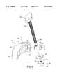
- FIG. 3is a side view of the workbench shown in FIGS. 1 and 2;
- FIG. 4is an end view of the workbench shown in FIGS. 1, 2, and 3;
- FIG. 5is a perspective view showing a piece of apparatus securely clamped to the upper surface of the workbench using rocker arm clamps which form an important part of the invention
- FIG. 6is an exploded view showing the detailed construction of one of the rocker arm-type clamps
- FIG. 7is a side view showing a rocker arm-type clamp shown in FIG. 6, in a fully assembled condition
- FIG. 8is an exploded view showing the constructional details of a second embodiment of the rocker arm-type clamp which is used in accordance with the present invention.
- FIG. 9is a perspective view showing the clamp depicted in FIG. 8, in a fully assembled condition.
- FIGS. 1-4show a preferred embodiment of the workbench 100 according to the present invention.
- this arrangementcomprises a trestle-like leg arrangement 102 wherein the legs of each pair are pivotally connected at the upper ends to a pair of cross members 104.
- the pairs of legs at each end of the tableare connected by a telescopically extendable brace member 106 and by a link 108 which, when the table is being folded, is arranged to induce one of each of the end pairs of legs to be moved vertically upward with respect to the other, and to cause the cross members 104, which bridge the upper ends of the legs, to become parallel with the other of the legs and to cause the table to fold into an essentially flat and compact arrangement suitable for storage.
- Two bench boards or table sections 110, 110are supported on the cross members 104 so that at least one is relatively moveable with respect to the other. That is to say, one or both of the bench boards 110, 110 are supported so as to be guidable along a guide track 112 which is formed in the upper surface of each of the cross members 104 via a support 114.
- a guide track 112which is formed in the upper surface of each of the cross members 104 via a support 114.
- Crank handles 118, 118which are provided on the ends of the threaded drive shafts, are used to enable a user to selectively rotate the shafts and to induce relative movement between the bench boards. This of course allows a user to selectively adjust the width of the workbench, and/or to open up a suitable gap between the two bench boards 110, 110 as the situation demands.
- the bench boards 110, 110are formed with a plurality of keyhole-like slots 120 which permit rocker arm clamps 122, as they will be referred to, to be selectively positioned about the top of the workbench 100 in accordance with the operators requirements.
- the clamps 122are arranged to be disposed through the circular opening at the end of each of the slots 120 and to be moved along the slot until the threaded shaft 126 (which will be disclosed in more detail herein later) is received in a narrower portion of a slot 120 so that a washer 128 and stopper 130 arrangement, which is provided at the bottom of the shaft 126, engages the lower surface of a bench board in which it is disposed.
- the inventionis not limited to the slot pattern which is illustrated in FIGS. 1 and 2, and that any other combination which is deemed desirable can be employed.
- the present inventionis not limited to clamping pieces of apparatus to the top of the table and can easily be used to secure work pieces such as the piece of large diameter pipe. This can be accomplished by setting the gap between the two bench boards 110 to a distance which is less than the diameter of the pipe and, if necessary, setting wedge pieces against either side of the pipe and subsequently clamping the wedge pieces in position using the rocker arm clamps 122.
- FIGS. 6 and 7show details of a first embodiment of a rocker arm clamp 122 which is used in accordance with the present invention.
- this devicecomprises what shall be referred to as a rocker arm 132 which is asymmetrically arranged about an axis A1 of rotation which passes through a circular bore 134 formed laterally through the arm 132 at a position which is closer to one end than the other.
- the engagement finger 136 which is formed on the longer portion of the rocker arm 132is arranged to extend down at a predetermined angle (alpha) which is greater than the angle (beta) at which the engagement finger 138 which is formed on the shorter portion of the arm 132 is arranged to extend down therefrom.
- the threaded bolt 126is arranged to extend through a vertically oriented bore 140 formed through the arm and which is such that its axis A2 intersects the axis A1 about which the rocker arm 122 is vertically pivotable.
- the arm 132is of course pivotal in the horizontal direction about the axis A2.
- a so-called "quick nut” 142is separately disposed in the bore 134.
- This quick nut 142is formed with a transverse bore 144 which is tapped in a manner wherein screw threads 146 are formed only on one side thereof.
- the bore 144is slightly oblong so as to permit the quick nut 142 to be moved axially along the bore 134 so that the threads 146 which are formed in the bore can be moved out of engagement with the threads on the bolt 126 and thus permit the quick nut 142 to slide on the bolt 142 without the need for its rotation.
- the lower end of the bolt 126is received in a tapped bore 148 that is formed in a clamp stabilizer or stopper 150.
- a roll pin 152is disposed through the transverse bore 154 which is formed in the lower end of the bolt 126 and passes through the lower end of the clamp stabilizer 150 so as to prevent relative rotation between the stabilizer 150 and the bolt 126 during usage of the clamp.
- the washer 128which is disposed about the bolt 126 is arranged to sit on top of a larger diameter portion of the clamp stabilizer 150. This washer 128, of course, is the member that actually engages the lower surface of a bench board 110.
- the asymmetrical arrangement of the rocker armallows the disposition such as shown in FIG. 5, wherein the engagement finger 138 formed on the shorter end of the rocker arm 132 engages the surface of the bench board 110 on which it is mounted, in a manner wherein a reaction which is produced causes the rocker arm 132 to pivot around the axis A1 and to drive the engagement finger 136 of the longer portion of the rocker arm 132, down into engagement with a surface of the object/work piece to be secured to the top of the workbench 100.
- the operation of the quick nut arrangement 142is such that manually applied pressure on one end of the nut 142 can be used to move it axially along the bore 134 formed in the rocker arm 132, to a position where disengagement between the threads on the bolt 126 and those formed in the quick nut 142, is achieved.
- the rocker arm 132can be quickly and easily positioned in the required manner, wherein the engagement finger 136 engages the work piece or the like, and the engagement finger 138 engages a surface of the bench board 110 over which it is disposed.
- FIGS. 8 and 9shows a second embodiment of the rocker arm clamp 222 which can be used in accordance with the present invention.
- the quick nut 242is disposed in a blind bore 234.
- a spring 256is disposed in the bore 243 between the inboard end of the quick nut 242 and the blind end of the bore.
- the nut 242is formed with a flange 242A that limits the amount by which it can be forced into the bore 234 the bias of the spring 256.
- the distance between the inboard surface of the flange 242A and the threaded surface formed in the bore 244is selected to permit an operator to press the exposed end of the quick nut 242 and to force it into the bore 234 by an amount sufficient to achieve disengagement between the bolt 226 and the threads 246 formed in the bore 244.
- the quick nut 242will, under the bias of the spring 256, move to a position wherein engagement between the bolt 226 and the threads 246 in the bore is re-established. Inasmuch as the bolt 226 passes through the quick nut per se, no further actual movement of the quick nut 242 under the influence of the spring 256 is permitted, once engagement between the threads has occurred.
- This embodimentfurther features a quick nut lock arrangement 260.
- This arrangementcomprises a molded member which can be disposed through a through bore 262 formed in the rocker arm 232 adjacent bore 234 so as to be pivotable about axis which is parallel to the axis about which the main body of the rocker arm 232 is pivotable.
- the shaft portion 260A of this lock arrangement which is received in the boreis formed with a split barbed end 260B which permits its insertion and self locking within the bore 262.
- a quick nut lock member 260Cwhich is formed at the end of the shaft member 260A is arranged to be pivotable and to be arranged so that, as shown in FIG.
Landscapes
- Engineering & Computer Science (AREA)
- Mechanical Engineering (AREA)
- Jigs For Machine Tools (AREA)
Abstract
Description
Claims (49)
Priority Applications (2)
| Application Number | Priority Date | Filing Date | Title |
|---|---|---|---|
| US09/187,338US6113088A (en) | 1998-11-06 | 1998-11-06 | Adjustable workbench having quick action clamps |
| PCT/US1999/026244WO2000027581A1 (en) | 1998-11-06 | 1999-11-08 | Adjustable workbench having quick action clamps |
Applications Claiming Priority (1)
| Application Number | Priority Date | Filing Date | Title |
|---|---|---|---|
| US09/187,338US6113088A (en) | 1998-11-06 | 1998-11-06 | Adjustable workbench having quick action clamps |
Publications (1)
| Publication Number | Publication Date |
|---|---|
| US6113088Atrue US6113088A (en) | 2000-09-05 |
Family
ID=22688570
Family Applications (1)
| Application Number | Title | Priority Date | Filing Date |
|---|---|---|---|
| US09/187,338Expired - LifetimeUS6113088A (en) | 1998-11-06 | 1998-11-06 | Adjustable workbench having quick action clamps |
Country Status (2)
| Country | Link |
|---|---|
| US (1) | US6113088A (en) |
| WO (1) | WO2000027581A1 (en) |
Cited By (43)
| Publication number | Priority date | Publication date | Assignee | Title |
|---|---|---|---|---|
| US6505552B1 (en)* | 1998-10-22 | 2003-01-14 | James D. Larson | Silk screen tensioning system |
| US6575444B1 (en)* | 1999-04-06 | 2003-06-10 | Abb Body In White | Method of holding a part in position in an assembly station |
| US20030214088A1 (en)* | 2002-05-15 | 2003-11-20 | Huei-Yu Chang | Foldable workbench |
| US20030213350A1 (en)* | 2002-05-16 | 2003-11-20 | Chin-Chin Chang | Circular saw having workpiece clamping device |
| US20050184440A1 (en)* | 2004-02-20 | 2005-08-25 | Innolux Display Corp. | Assembling appaatus for liquid crystal displays |
| EP1527848A3 (en)* | 2003-10-31 | 2005-10-12 | Techtronic Industries Co., Ltd. | Collapsible stand for a bench-top power tool |
| US20060254480A1 (en)* | 2005-05-11 | 2006-11-16 | Efraim Haimoff | Multi-shelf collapsible table |
| US20070084526A1 (en)* | 2005-10-05 | 2007-04-19 | Uwe Radermacher | Tool arrangement for gripping in a gripping table |
| USD572937S1 (en)* | 2006-02-10 | 2008-07-15 | H.G.V. Haus Und Garten-Marketing Und Vertriebsgesellschaft Mbh | Workbench |
| USD577507S1 (en)* | 2007-05-03 | 2008-09-30 | Freeform Design & Innovation Limited | Workbench |
| US20080258369A1 (en)* | 2002-02-19 | 2008-10-23 | Frank Michael John Kent | Variable geometry worktable |
| US20080265480A1 (en)* | 2004-07-26 | 2008-10-30 | Frank Michael John Kent | Worktable Clamping and Folding Apparatus and Methods for Operating Same |
| US20090000522A1 (en)* | 2005-12-08 | 2009-01-01 | Freeform Design & Innovation Limited | Frame assembly for a folding workbench |
| US20090065992A1 (en)* | 2007-09-07 | 2009-03-12 | Credo Technology Corporation | Dog hole layout for a workbench system |
| US20090084929A1 (en)* | 2006-06-12 | 2009-04-02 | Metabowerke Gmbh | Machine Stand |
| US20090100674A1 (en)* | 2007-10-17 | 2009-04-23 | Adc Tecommunications, Inc. | Cable splint |
| US20090107367A1 (en)* | 2007-10-31 | 2009-04-30 | Stephen Edward Smythe | Portable power tool rest |
| US20090160114A1 (en)* | 2007-09-18 | 2009-06-25 | Bernhardt Randall J | 90 degree table mount |
| US20090269170A1 (en)* | 2008-04-24 | 2009-10-29 | Gm Global Technology Operations, Inc. | Panels-Off Coating Process and Carrier Utilizing Panel Rotation |
| USD614887S1 (en)* | 2007-07-16 | 2010-05-04 | Black & Decker Inc. | Portable workbench |
| US7764079B1 (en) | 2007-01-31 | 2010-07-27 | SemiProbe LLC | Modular probe system |
| US20120119428A1 (en)* | 2010-11-15 | 2012-05-17 | Kirchgessner William A | Wall mounted work bench |
| US8794614B2 (en)* | 2010-09-23 | 2014-08-05 | Lasse Friis | Expandable workbench and a method of use |
| US20140359995A1 (en)* | 2013-06-05 | 2014-12-11 | International Business Machines Corporation | Constrained die adhesion cure process |
| US20150016813A1 (en)* | 2013-07-15 | 2015-01-15 | Matthew Swaggart | Camera Hold Fast Accessory Clip |
| US20150028611A1 (en)* | 2008-09-03 | 2015-01-29 | Honda Motor Co., Ltd. | Workpiece mounting system, workpiece mounting method, sunroof unit holding device, and sunroof unit holding method |
| US20150098772A1 (en)* | 2013-10-07 | 2015-04-09 | Norman D. Nelson | Electric hydraulic catalyst loading and unloading device and methods therefor |
| USD751845S1 (en)* | 2014-02-03 | 2016-03-22 | Bruno Mallinger | Workbench |
| WO2016114852A1 (en)* | 2015-01-15 | 2016-07-21 | Intel Corporation | Apparatus, method, and system for calibrating one or more motion sensors |
| US9415503B1 (en)* | 2012-06-29 | 2016-08-16 | Joseph R. Ferragonio | Portable tool box |
| USD781083S1 (en)* | 2015-02-01 | 2017-03-14 | Jinhua Wis Tools Co., Ltd | Workbench |
| US9789601B1 (en)* | 2016-04-27 | 2017-10-17 | Alfred H. Judge | Woodworker's light rail system |
| WO2018167480A1 (en)* | 2017-03-14 | 2018-09-20 | Andrew Birch | Apparatus for Mounting a Tool to a Vice |
| CN109013223A (en)* | 2018-10-12 | 2018-12-18 | 湖南航天机电设备与特种材料研究所 | A kind of printed board support fixture |
| USD842015S1 (en) | 2016-11-16 | 2019-03-05 | Kreg Enterprises, Inc. | Mobile and collapsible workbench |
| CN109877734A (en)* | 2019-02-18 | 2019-06-14 | 江苏大学 | A general vehicle fuel tank turning device |
| US20190193949A1 (en)* | 2017-12-22 | 2019-06-27 | Fanuc Corporation | Workpiece holding jig |
| US10507571B2 (en) | 2016-10-11 | 2019-12-17 | Micro Jig, Inc. | Panel with fixture retaining features and modular assemblies made using multiple panels |
| CN111790950A (en)* | 2020-08-03 | 2020-10-20 | 东莞华南设计创新院 | Automatic CNC double trimming processing device |
| USD925065S1 (en) | 2018-06-22 | 2021-07-13 | Kreg Enterprises, Inc. | Track horse |
| US11084163B2 (en)* | 2016-11-16 | 2021-08-10 | Kreg Enterprises, Inc. | Mobile project center system |
| US20230014368A1 (en)* | 2021-07-09 | 2023-01-19 | Triple Win Technology(Shenzhen) Co.Ltd. | Disassembling device |
| US20240391087A1 (en)* | 2020-08-31 | 2024-11-28 | Sawstop Holding Llc | Folding stand with securing mechanism |
Families Citing this family (2)
| Publication number | Priority date | Publication date | Assignee | Title |
|---|---|---|---|---|
| DE102009018280A1 (en)* | 2009-04-21 | 2010-11-04 | Christian Karl Siebenwurst Modellfabrik Und Formenbau Gmbh & Co. Kg | Clamping device for clamping cuboidal workpiece in processing device, has clamping element designed for detachably connecting elements with each other, where connecting elements are formed with respective threaded sections |
| GB201703604D0 (en)* | 2017-03-07 | 2017-04-19 | Power Box Ag | Clamping apparatus |
Citations (15)
| Publication number | Priority date | Publication date | Assignee | Title |
|---|---|---|---|---|
| US2351436A (en)* | 1943-01-09 | 1944-06-13 | Charles T Ketz | Work clamp |
| US3712606A (en)* | 1970-12-04 | 1973-01-23 | G Cole | Clamping device |
| US4154435A (en)* | 1978-02-22 | 1979-05-15 | The Black And Decker Manufacturing Company | Portable workbench |
| US4248411A (en)* | 1979-05-15 | 1981-02-03 | Black And Decker, Inc. | Apparatus for supporting a work piece |
| US4265436A (en)* | 1979-08-10 | 1981-05-05 | Black & Decker Inc. | Workpiece support device and auxiliary support body arrangement |
| US4278243A (en)* | 1976-02-19 | 1981-07-14 | Black & Decker Inc. | Foldable workbench |
| US4352489A (en)* | 1979-05-29 | 1982-10-05 | Black & Decker Inc. | Small compact lightweight portable vise suitable for use by model makers and hobbyists |
| US4378107A (en)* | 1980-03-28 | 1983-03-29 | Black & Decker Inc. | Workpiece support and clamping assembly |
| US4442779A (en)* | 1981-12-24 | 1984-04-17 | Black & Decker Inc. | Unitary latching and release means for portable foldable workbench |
| US4470586A (en)* | 1982-07-09 | 1984-09-11 | Spencer Philip P | Machine clamp rockable in T slot |
| US4958813A (en)* | 1989-09-28 | 1990-09-25 | Delaware Capital Formation, Inc. | Die clamp |
| US5275391A (en)* | 1992-08-10 | 1994-01-04 | Lee Valley Tools Ltd. | Bench hold-down |
| US5681034A (en)* | 1994-05-28 | 1997-10-28 | Wolfcraft Gmbh | Foldable worktable |
| US5692734A (en)* | 1993-07-15 | 1997-12-02 | American Tool Companies, Inc. | Clamp structure |
| US5836574A (en)* | 1996-04-04 | 1998-11-17 | Park; Sung-Bu | Clamping device of machine tool |
- 1998
- 1998-11-06USUS09/187,338patent/US6113088A/ennot_activeExpired - Lifetime
- 1999
- 1999-11-08WOPCT/US1999/026244patent/WO2000027581A1/enactiveApplication Filing
Patent Citations (15)
| Publication number | Priority date | Publication date | Assignee | Title |
|---|---|---|---|---|
| US2351436A (en)* | 1943-01-09 | 1944-06-13 | Charles T Ketz | Work clamp |
| US3712606A (en)* | 1970-12-04 | 1973-01-23 | G Cole | Clamping device |
| US4278243A (en)* | 1976-02-19 | 1981-07-14 | Black & Decker Inc. | Foldable workbench |
| US4154435A (en)* | 1978-02-22 | 1979-05-15 | The Black And Decker Manufacturing Company | Portable workbench |
| US4248411A (en)* | 1979-05-15 | 1981-02-03 | Black And Decker, Inc. | Apparatus for supporting a work piece |
| US4352489A (en)* | 1979-05-29 | 1982-10-05 | Black & Decker Inc. | Small compact lightweight portable vise suitable for use by model makers and hobbyists |
| US4265436A (en)* | 1979-08-10 | 1981-05-05 | Black & Decker Inc. | Workpiece support device and auxiliary support body arrangement |
| US4378107A (en)* | 1980-03-28 | 1983-03-29 | Black & Decker Inc. | Workpiece support and clamping assembly |
| US4442779A (en)* | 1981-12-24 | 1984-04-17 | Black & Decker Inc. | Unitary latching and release means for portable foldable workbench |
| US4470586A (en)* | 1982-07-09 | 1984-09-11 | Spencer Philip P | Machine clamp rockable in T slot |
| US4958813A (en)* | 1989-09-28 | 1990-09-25 | Delaware Capital Formation, Inc. | Die clamp |
| US5275391A (en)* | 1992-08-10 | 1994-01-04 | Lee Valley Tools Ltd. | Bench hold-down |
| US5692734A (en)* | 1993-07-15 | 1997-12-02 | American Tool Companies, Inc. | Clamp structure |
| US5681034A (en)* | 1994-05-28 | 1997-10-28 | Wolfcraft Gmbh | Foldable worktable |
| US5836574A (en)* | 1996-04-04 | 1998-11-17 | Park; Sung-Bu | Clamping device of machine tool |
Cited By (63)
| Publication number | Priority date | Publication date | Assignee | Title |
|---|---|---|---|---|
| US6505552B1 (en)* | 1998-10-22 | 2003-01-14 | James D. Larson | Silk screen tensioning system |
| US6575444B1 (en)* | 1999-04-06 | 2003-06-10 | Abb Body In White | Method of holding a part in position in an assembly station |
| US20030193121A1 (en)* | 1999-04-06 | 2003-10-16 | Abb Body In White | Method of holding a part in position in an assembly station |
| US6845974B2 (en) | 1999-04-06 | 2005-01-25 | Abb Body In White | Method of holding a part in position in an assembly station |
| US20080258369A1 (en)* | 2002-02-19 | 2008-10-23 | Frank Michael John Kent | Variable geometry worktable |
| US20030214088A1 (en)* | 2002-05-15 | 2003-11-20 | Huei-Yu Chang | Foldable workbench |
| US6769674B2 (en)* | 2002-05-15 | 2004-08-03 | Huei-Yu Chang | Foldable workbench |
| US20030213350A1 (en)* | 2002-05-16 | 2003-11-20 | Chin-Chin Chang | Circular saw having workpiece clamping device |
| EP1527848A3 (en)* | 2003-10-31 | 2005-10-12 | Techtronic Industries Co., Ltd. | Collapsible stand for a bench-top power tool |
| US20050184440A1 (en)* | 2004-02-20 | 2005-08-25 | Innolux Display Corp. | Assembling appaatus for liquid crystal displays |
| US20080265480A1 (en)* | 2004-07-26 | 2008-10-30 | Frank Michael John Kent | Worktable Clamping and Folding Apparatus and Methods for Operating Same |
| US7418907B2 (en)* | 2005-05-11 | 2008-09-02 | Keter Plastic Ltd. | Multi-shelf collapsible table |
| US20060254480A1 (en)* | 2005-05-11 | 2006-11-16 | Efraim Haimoff | Multi-shelf collapsible table |
| US20070084526A1 (en)* | 2005-10-05 | 2007-04-19 | Uwe Radermacher | Tool arrangement for gripping in a gripping table |
| US20090000522A1 (en)* | 2005-12-08 | 2009-01-01 | Freeform Design & Innovation Limited | Frame assembly for a folding workbench |
| USD572937S1 (en)* | 2006-02-10 | 2008-07-15 | H.G.V. Haus Und Garten-Marketing Und Vertriebsgesellschaft Mbh | Workbench |
| US20090084929A1 (en)* | 2006-06-12 | 2009-04-02 | Metabowerke Gmbh | Machine Stand |
| US20100277195A1 (en)* | 2007-01-31 | 2010-11-04 | SemiProbe LLC | Modular Probe System |
| US7764079B1 (en) | 2007-01-31 | 2010-07-27 | SemiProbe LLC | Modular probe system |
| USD577507S1 (en)* | 2007-05-03 | 2008-09-30 | Freeform Design & Innovation Limited | Workbench |
| USD614887S1 (en)* | 2007-07-16 | 2010-05-04 | Black & Decker Inc. | Portable workbench |
| US20090065992A1 (en)* | 2007-09-07 | 2009-03-12 | Credo Technology Corporation | Dog hole layout for a workbench system |
| US8403314B2 (en)* | 2007-09-07 | 2013-03-26 | Robert Bosch Gmbh | Dog hole layout for a workbench system |
| US8733750B2 (en)* | 2007-09-18 | 2014-05-27 | Urban Manufacturing, Inc. | 90° table mount |
| US20090160114A1 (en)* | 2007-09-18 | 2009-06-25 | Bernhardt Randall J | 90 degree table mount |
| US8601670B2 (en) | 2007-10-17 | 2013-12-10 | Adc Telecommunications, Inc. | Cable splint |
| US7926797B2 (en)* | 2007-10-17 | 2011-04-19 | Adc Telecommunications, Inc. | Cable splint |
| US20110154643A1 (en)* | 2007-10-17 | 2011-06-30 | Adc Telecommunications, Inc. | Cable splint |
| US20090100674A1 (en)* | 2007-10-17 | 2009-04-23 | Adc Tecommunications, Inc. | Cable splint |
| US20090107367A1 (en)* | 2007-10-31 | 2009-04-30 | Stephen Edward Smythe | Portable power tool rest |
| US8215623B2 (en)* | 2008-04-24 | 2012-07-10 | GM Global Technology Operations LLC | Panels-off coating process and carrier utilizing panel rotation |
| US20090269170A1 (en)* | 2008-04-24 | 2009-10-29 | Gm Global Technology Operations, Inc. | Panels-Off Coating Process and Carrier Utilizing Panel Rotation |
| US20150028611A1 (en)* | 2008-09-03 | 2015-01-29 | Honda Motor Co., Ltd. | Workpiece mounting system, workpiece mounting method, sunroof unit holding device, and sunroof unit holding method |
| US9592611B2 (en)* | 2008-09-03 | 2017-03-14 | Honda Motor Co., Ltd. | Workpiece mounting system, workpiece mounting method, sunroof unit holding device, and sunroof unit holding method |
| US8794614B2 (en)* | 2010-09-23 | 2014-08-05 | Lasse Friis | Expandable workbench and a method of use |
| US20120119428A1 (en)* | 2010-11-15 | 2012-05-17 | Kirchgessner William A | Wall mounted work bench |
| US9216507B2 (en)* | 2010-11-15 | 2015-12-22 | William A. Kirchgessner | Wall mounted work bench |
| US9415503B1 (en)* | 2012-06-29 | 2016-08-16 | Joseph R. Ferragonio | Portable tool box |
| US20140359995A1 (en)* | 2013-06-05 | 2014-12-11 | International Business Machines Corporation | Constrained die adhesion cure process |
| US9305894B2 (en)* | 2013-06-05 | 2016-04-05 | Globalfoundries Inc. | Constrained die adhesion cure process |
| US20150016813A1 (en)* | 2013-07-15 | 2015-01-15 | Matthew Swaggart | Camera Hold Fast Accessory Clip |
| US9020335B2 (en)* | 2013-07-15 | 2015-04-28 | Matthew Swaggart | Camera hold fast accessory clip |
| CN104645826A (en)* | 2013-10-07 | 2015-05-27 | 巴布科克和威尔科克斯能量产生集团公司 | Electric hydraulic catalyst loading and unloading device and methods therefor |
| US20150098772A1 (en)* | 2013-10-07 | 2015-04-09 | Norman D. Nelson | Electric hydraulic catalyst loading and unloading device and methods therefor |
| US9896308B2 (en)* | 2013-10-07 | 2018-02-20 | The Babcock & Wilcox Company | Electric hydraulic catalyst loading and unloading device and methods therefor |
| USD751845S1 (en)* | 2014-02-03 | 2016-03-22 | Bruno Mallinger | Workbench |
| WO2016114852A1 (en)* | 2015-01-15 | 2016-07-21 | Intel Corporation | Apparatus, method, and system for calibrating one or more motion sensors |
| USD781083S1 (en)* | 2015-02-01 | 2017-03-14 | Jinhua Wis Tools Co., Ltd | Workbench |
| US9789601B1 (en)* | 2016-04-27 | 2017-10-17 | Alfred H. Judge | Woodworker's light rail system |
| US11279020B2 (en) | 2016-10-11 | 2022-03-22 | Henry Wang | Panel with fixture retaining features and modular assemblies made using multiple panels |
| US10507571B2 (en) | 2016-10-11 | 2019-12-17 | Micro Jig, Inc. | Panel with fixture retaining features and modular assemblies made using multiple panels |
| USD842015S1 (en) | 2016-11-16 | 2019-03-05 | Kreg Enterprises, Inc. | Mobile and collapsible workbench |
| US11084163B2 (en)* | 2016-11-16 | 2021-08-10 | Kreg Enterprises, Inc. | Mobile project center system |
| WO2018167480A1 (en)* | 2017-03-14 | 2018-09-20 | Andrew Birch | Apparatus for Mounting a Tool to a Vice |
| US20190193949A1 (en)* | 2017-12-22 | 2019-06-27 | Fanuc Corporation | Workpiece holding jig |
| US11034528B2 (en)* | 2017-12-22 | 2021-06-15 | Fanuc Corporation | Workpiece holding jig |
| USD925065S1 (en) | 2018-06-22 | 2021-07-13 | Kreg Enterprises, Inc. | Track horse |
| CN109013223A (en)* | 2018-10-12 | 2018-12-18 | 湖南航天机电设备与特种材料研究所 | A kind of printed board support fixture |
| CN109877734A (en)* | 2019-02-18 | 2019-06-14 | 江苏大学 | A general vehicle fuel tank turning device |
| CN111790950A (en)* | 2020-08-03 | 2020-10-20 | 东莞华南设计创新院 | Automatic CNC double trimming processing device |
| US20240391087A1 (en)* | 2020-08-31 | 2024-11-28 | Sawstop Holding Llc | Folding stand with securing mechanism |
| US20230014368A1 (en)* | 2021-07-09 | 2023-01-19 | Triple Win Technology(Shenzhen) Co.Ltd. | Disassembling device |
| US11872661B2 (en)* | 2021-07-09 | 2024-01-16 | Triple Win Technology(Shenzhen) Co.Ltd. | Disassembling device |
Also Published As
| Publication number | Publication date |
|---|---|
| WO2000027581A1 (en) | 2000-05-18 |
Similar Documents
| Publication | Publication Date | Title |
|---|---|---|
| US6113088A (en) | Adjustable workbench having quick action clamps | |
| US6986370B1 (en) | Table saw | |
| US20050006002A1 (en) | Work bench | |
| US4127260A (en) | Workbench with quick setting vise structure | |
| CA1057806A (en) | Workpiece supporting and clamping apparatus | |
| US4291869A (en) | Workbench | |
| US4199135A (en) | Foldable workbench | |
| CA2620463C (en) | Bracket | |
| US20080258369A1 (en) | Variable geometry worktable | |
| US5868185A (en) | Folding workbench system | |
| US20040250901A1 (en) | Collapsible stand | |
| WO2007046912A2 (en) | Folding work platform | |
| US7232120B2 (en) | Quick clamping system for a workbench | |
| US5560449A (en) | Adjustable trestle sawhorse | |
| US4494431A (en) | Portable radial arm saw | |
| CA1043135A (en) | Dowel bore forming and routing jig | |
| CA1168286A (en) | Workpiece support and clamping assembly | |
| CN110125886A (en) | Clamping device | |
| US4494591A (en) | Tilting table for a woodworking tool | |
| EP0353253A1 (en) | Holders | |
| EP0603344A1 (en) | Clamping devices | |
| US4909495A (en) | Work bench | |
| GB2109675A (en) | Improvements in and relating to trestles | |
| GB2281528A (en) | Clamping device | |
| US4911418A (en) | Work holder |
Legal Events
| Date | Code | Title | Description |
|---|---|---|---|
| AS | Assignment | Owner name:VERMONT AMERICAN CORPORATION, KENTUCKY Free format text:ASSIGNMENT OF ASSIGNORS INTEREST;ASSIGNORS:GAKHAR, VED P.;HALE, W. MILES;SZYMANSKI, DONALD M.;REEL/FRAME:009572/0959 Effective date:19981026 | |
| STCF | Information on status: patent grant | Free format text:PATENTED CASE | |
| FEPP | Fee payment procedure | Free format text:PAYOR NUMBER ASSIGNED (ORIGINAL EVENT CODE: ASPN); ENTITY STATUS OF PATENT OWNER: LARGE ENTITY | |
| FPAY | Fee payment | Year of fee payment:4 | |
| AS | Assignment | Owner name:CREDO TECHNOLOGY CORPORATION, DELAWARE Free format text:ASSIGNMENT OF ASSIGNORS INTEREST;ASSIGNOR:ROBERT BOSCH TOOL CORPORATION;REEL/FRAME:014615/0215 Effective date:20030101 Owner name:ROBERT BOSCH TOOL CORPORATION, KENTUCKY Free format text:COMBINED MERGER AND CHANGE OF NAME;ASSIGNOR:VERMONT AMERICAN CORPORATION;REEL/FRAME:014609/0574 Effective date:20021227 | |
| FPAY | Fee payment | Year of fee payment:8 | |
| FPAY | Fee payment | Year of fee payment:12 |