US6113062A - Squeeze clamp - Google Patents
Squeeze clampDownload PDFInfo
- Publication number
- US6113062A US6113062AUS09/238,767US23876799AUS6113062AUS 6113062 AUS6113062 AUS 6113062AUS 23876799 AUS23876799 AUS 23876799AUS 6113062 AUS6113062 AUS 6113062A
- Authority
- US
- United States
- Prior art keywords
- clamp
- strip
- squeeze
- tubing
- narrow strip
- Prior art date
- Legal status (The legal status is an assumption and is not a legal conclusion. Google has not performed a legal analysis and makes no representation as to the accuracy of the status listed.)
- Expired - Lifetime
Links
- 238000003825pressingMethods0.000claimsdescription5
- 230000001154acute effectEffects0.000claimsdescription3
- 238000005728strengtheningMethods0.000abstract1
- 239000012530fluidSubstances0.000description3
- 238000004519manufacturing processMethods0.000description3
- 238000004806packaging method and processMethods0.000description2
- 238000005452bendingMethods0.000description1
- 230000000903blocking effectEffects0.000description1
- 239000008280bloodSubstances0.000description1
- 210000004369bloodAnatomy0.000description1
- 238000009434installationMethods0.000description1
- 230000014759maintenance of locationEffects0.000description1
- 239000000463materialSubstances0.000description1
- 230000002787reinforcementEffects0.000description1
- 230000003014reinforcing effectEffects0.000description1
Images


Classifications
- A—HUMAN NECESSITIES
- A61—MEDICAL OR VETERINARY SCIENCE; HYGIENE
- A61M—DEVICES FOR INTRODUCING MEDIA INTO, OR ONTO, THE BODY; DEVICES FOR TRANSDUCING BODY MEDIA OR FOR TAKING MEDIA FROM THE BODY; DEVICES FOR PRODUCING OR ENDING SLEEP OR STUPOR
- A61M39/00—Tubes, tube connectors, tube couplings, valves, access sites or the like, specially adapted for medical use
- A61M39/22—Valves or arrangement of valves
- A61M39/28—Clamping means for squeezing flexible tubes, e.g. roller clamps
- A61M39/284—Lever clamps
Definitions
- Squeeze clamps for flexible tubingsuch as the well known Halkey-Roberts clamp
- Buckman et al. U.S. Pat. No. 3,942,228shows a squeeze clamp similar to the known Halkey-Roberts clamp in which the clamp comprises a strip of plastic which is bent back on itself, so that the ends of the clamp are adjacent to each other.
- the clamphas open tube apertures, to permit it to be laterally placed onto flexible tubing and used to permit the opening of flow, or the blocking of flow, through the tubing as may be desired.
- clamps in which the tubing apertures have side slots for lateral connectionare thus weakened thereby, since the remaining portion of the strip that is laterally adjacent to the side slot is substantially narrowed and thus weakened by the presence of the side slot and aperture. This can interfere with the function of the squeeze clamp.
- squeeze clampsare provided which utilize side slots connecting to their tubing apertures so that the clamps may be laterally placed onto flexible tubing, and do not need to be threaded onto the tubing from the ends thereof.
- these clampsalthough overall no wider than corresponding clamps having closed tube apertures without side slots, can still exhibit good quality dynamic action largely free of involuntary torsion or lateral twisting of the clamp, as one attempts to close it, because of weakness of the clamp adjacent the tube apertures with their side slots.
- the clampsmay be packaged with sets in a typical coiled form without a need to significantly enlarge the packaging, since the clamps remain overall of the same size as present conventional Halkey-Roberts clamps. However, they have the added advantage of being laterally applicable to flexible tubing of manufactured sets when and as desired.
- a squeeze clamp for flexible tubinghaving open and closed positions for allowing flow through the tubing or preventing such flow.
- the squeeze clampcomprises a strip of plastic having first and second opposed side edges and first and second ends.
- the stripis bent back on itself, in its natural, unstressed position, so that the ends of the strip are adjacent to each other, in the typical manner of clamps that resemble Halkey-Roberts clamps.
- the stripdefines a pair of spaced apertures to permit a flexible tube to extend through and be carried by the clamp.
- the aperturesextend laterally through the first side edge of the strip.
- the aperturesare each located next to a narrow strip portion which is connected to wider strip portions on either side of the narrow strip portion. This of course is a consequence of the existence of the spaced apertures and their lateral slots through the first side edge of the strip, leaving only a portion of the width of the strip intact.
- the narrow strip portion adjacent to at least one of said aperturesextends laterally outwardly beyond the second side edge of the rest of the plastic strip, to strengthen the narrow strip portion without significantly adding to the overall width of the entire squeeze clamp.
- involuntary torsion or lateral twistingcan be reduced or avoided as the clamp is opened and particularly closed, while at the same time the clamp can be laterally applied to intact tube sets without being threaded over an end thereof.
- the one narrow strip portion described aboveis located adjacent to an area where the strip bends back on itself, with this area serving as a hinge.
- the reenforcement provided by this inventionis particularly valuable in that circumstance.
- the narrow strip portionis relatively narrow with respect to the normal second side edge of the strip. The term is not intended to limit the extent of the outwardly bulging portion of the narrow second side strip portion.
- the squeeze clamp of this inventionmay share in some of the characteristics of the squeeze clamp disclosed in co-pending Utterberg U.S. application Ser. No. 08/943,672, filed Oct. 3, 1997.
- the squeeze clampmay carry at least one projecting portion, which will be carried by one section of the strip to close and seal the flexible tube carried by the clamp on clamp closing by pressing the tube against another section of strip.
- a first strip endmay define a first latch for engagement and releasable locking with a second latch of a second strip end.
- the first endmay also define a first projection extending toward the second end and having a length that substantially reduces or eliminates a gap between the first and second ends when the clamp is in its open position.
- the reduction of such a gap by the first projectioncan facilitate the mass production assembly of sets using the squeeze clamp, since squeeze clamps in bulk are less likely to hook together in a manner which is time consuming to separate.
- the second end of the squeeze clampcan carry a second projection extending outwardly from the second end in a direction which is substantially longitudinal of the direction of extension of tubing carried in the clamp. This can facilitate clamp opening.
- the second projectionis out of the way of the fingers of the user while pressing the first end of the clamp into closed position with the second end.
- the width of the squeeze clampneeds to be larger and stronger, with needed added strength being provided by the laterally outwardly bulging, narrow strip portion of portions provided by this invention.
- Available clamps on the marketare generally of a width of no more than 12 mm. for a flexible tube with an outer diameter of 4 mm.
- FIG. 1is a perspective view of the squeeze clamp of this invention in the open position
- FIG. 2is a side elevational view of the squeeze clamp of FIG. 1;
- FIG. 3is a front elevational view of the squeeze clamp of FIG. 1;
- FIG. 4is a perspective view of the squeeze clamp of FIG. 1 taken from the other side of the clamp.
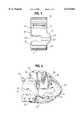
- FIG. 5is a side elevational view of the squeeze clamp of FIG. 2 in the closed position.
- squeeze clamp 10comprises an unitary strip of plastic having first and second opposed side edges 12, 14 (FIG. 3) and first and second ends 16, 18 as best shown in FIG. 2.
- a plastic strip 11makes up squeeze clamp 10, being bent back on itself in its natural, unstressed position so that the respective ends 16, 18 are adjacent to each other.
- strip 11 of the clampcomprises, in this embodiment, a pair of relatively straight portions 20, 22 (FIG. 2) separated by a curved, hinge portion 24 which flexes as the squeeze clamp moves by bending and releasing between open and closed positions.
- the clamp of FIGS. 1-4is shown in the open position, latching together in the closed position with their ends engaging as shown in FIG. 5.
- Clamp 10is shown in FIG. 2 to be carried on flexible tubing of a medical set 26, which is flexible, and may be squeezed shut in conventional manner when the clamp is in the closed position by the near engagement of opposed projections 28, 30.
- Clamp 10also defines a pair of spaced apertures 32, 34 to permit flexible tube 26 to extend through and be carried by the clamp.
- Clamp 10also defines a pair of latches 36, 38, which are configured to engage each other by abutting retention when clamp 10 is bent into the closed position.
- the clamphas an open position which is typically its natural, unstressed position. Thus, the clamp may be closed by squeezing straight portions 20, 22 together until latch surfaces 36, 38 snap into abutting relation. In this configuration, the two projections 28, 30 squeeze tubing 26 into a closed, fluid tight, sealed configuration, as is generally conventional in clamps of this overall type of design.
- the respective spaced apertures 32, 34have lateral slots 40 that each extend through side edge 12 of the strip as shown particularly in FIG. 3.
- a narrow strip portion 42is created, relative to the overall width of strip 11 and particularly relative to wider strip portions 44, 46 positioned on either side of narrow strip portion 42.
- narrow strip portions 42extend laterally outwardly beyond second side edge 14 of the rest of strip 11 to form an outward bulge 43.
- the width of narrow strip 42is substantially greater than it would be if it terminated at a straight extension of side edge 14, as indicated by dotted line 48.
- This extra material in narrow strip portion 42provides added strength and resistance against undesired torsion or twisting as particularly the clamp is being closed by a nurse in use of a set.
- the overall width of strip 11 along most of its lengthis not enlarged, which facilitates the use of a small package of a coiled set carrying the clamps of this invention.
- First strip end 16may also define a first projection 50 extending toward second end 18 and having a length that substantially reduces or eliminates the gap 52 between the first and second ends when the clamp is in its open position. As stated above, this can reduce the likelihood that the clamps in bulk hook together in a manner which is time-consuming to separate on a mass production basis.
- second end 18 of clamp 10can carry a second projection 54 ,which extends outwardly from second end 18 in a direction which is substantially longitudinal of the direction of extension of tubing carried in the clamp, to facilitate clamp opening.
- Second projection 54can thus be out of the way of the fingers of the user, while it serves to aid in opening of the clamp.
- second projection 54extends at an acute angle to tube 26 of about 30-45 degrees. This angle is typically reduced a bit when the clamp is in closed position, since second projection 54 is forced to rotate to a certain extent downwardly by the spring action of first end 16, with its latch 36 pressing latch 38 upwardly.
- Reinforcing ribs 56may also be provided to the straight section 20 of strip 11 to provide lateral reinforcement to projection 28.
- Aperture 58is provided between a pair of members 60, 62 that comprise a straight section 22, in order to provide strength with a minimum of plastic.
Landscapes
- Health & Medical Sciences (AREA)
- Heart & Thoracic Surgery (AREA)
- Pulmonology (AREA)
- Engineering & Computer Science (AREA)
- Anesthesiology (AREA)
- Biomedical Technology (AREA)
- Hematology (AREA)
- Life Sciences & Earth Sciences (AREA)
- Animal Behavior & Ethology (AREA)
- General Health & Medical Sciences (AREA)
- Public Health (AREA)
- Veterinary Medicine (AREA)
- Infusion, Injection, And Reservoir Apparatuses (AREA)
- Surgical Instruments (AREA)
- Polarising Elements (AREA)
- Pharmaceuticals Containing Other Organic And Inorganic Compounds (AREA)
- Clamps And Clips (AREA)
- Electrical Discharge Machining, Electrochemical Machining, And Combined Machining (AREA)
- Electric Double-Layer Capacitors Or The Like (AREA)
Abstract
Description
Claims (11)
Priority Applications (6)
| Application Number | Priority Date | Filing Date | Title |
|---|---|---|---|
| US09/238,767US6113062A (en) | 1999-01-28 | 1999-01-28 | Squeeze clamp |
| PCT/US2000/001726WO2000044434A1 (en) | 1999-01-28 | 2000-01-24 | Squeeze clamp |
| EP00907015AEP1146928B1 (en) | 1999-01-28 | 2000-01-24 | Squeeze clamp |
| DE60016562TDE60016562T2 (en) | 1999-01-28 | 2000-01-24 | PRESSURE TERMINAL |
| AT00907015TATE284243T1 (en) | 1999-01-28 | 2000-01-24 | PRESSURE CLAMP |
| AU28583/00AAU2858300A (en) | 1999-01-28 | 2000-01-24 | Squeeze clamp |
Applications Claiming Priority (1)
| Application Number | Priority Date | Filing Date | Title |
|---|---|---|---|
| US09/238,767US6113062A (en) | 1999-01-28 | 1999-01-28 | Squeeze clamp |
Publications (1)
| Publication Number | Publication Date |
|---|---|
| US6113062Atrue US6113062A (en) | 2000-09-05 |
Family
ID=22899225
Family Applications (1)
| Application Number | Title | Priority Date | Filing Date |
|---|---|---|---|
| US09/238,767Expired - LifetimeUS6113062A (en) | 1999-01-28 | 1999-01-28 | Squeeze clamp |
Country Status (6)
| Country | Link |
|---|---|
| US (1) | US6113062A (en) |
| EP (1) | EP1146928B1 (en) |
| AT (1) | ATE284243T1 (en) |
| AU (1) | AU2858300A (en) |
| DE (1) | DE60016562T2 (en) |
| WO (1) | WO2000044434A1 (en) |
Cited By (47)
| Publication number | Priority date | Publication date | Assignee | Title |
|---|---|---|---|---|
| US6234448B1 (en) | 1998-11-12 | 2001-05-22 | Medivice Systems Ltd. | Pinch clamp |
| US6482190B1 (en)* | 1997-02-06 | 2002-11-19 | C.R. Bard Inc, | Outlet tube device for urinary drainage bag |
| US6602240B2 (en)* | 2000-02-15 | 2003-08-05 | Thomas J. Fogarty | Method and device for maintaining a seal |
| US6644618B1 (en)* | 1999-06-10 | 2003-11-11 | Enrico Balbo | Fast-fit clamp for regulating flow along flexible tubes, in particular for medical use |
| US20040089828A1 (en)* | 2002-10-18 | 2004-05-13 | Werth Albert A. | Conduit clamp |
| US6742760B2 (en) | 2001-09-27 | 2004-06-01 | Baxter International Inc. | Flow control device |
| US20050215975A1 (en)* | 2002-01-31 | 2005-09-29 | Jean-Marie Mathias | Irreversibly closable flow control clamp |
| US20060081797A1 (en)* | 2004-10-18 | 2006-04-20 | Z-Man Corporation | Pinch clamp |
| US20060155227A1 (en)* | 2002-10-01 | 2006-07-13 | Microtek Medical, Inc. | Vacuum splint device |
| US20060169934A1 (en)* | 2005-01-28 | 2006-08-03 | Twin Bay Medical, Inc. | Conduit clamp |
| US20080082079A1 (en)* | 2006-09-28 | 2008-04-03 | Tyco Healthcare Group Lp | Low profile catheter assembly |
| US20080108954A1 (en)* | 2006-11-02 | 2008-05-08 | Jean-Marie Mathias | Flow Controllers |
| US20080108955A1 (en)* | 2006-11-02 | 2008-05-08 | Blickhan Bryan J | Flow Controllers |
| US20080312578A1 (en)* | 2007-04-12 | 2008-12-18 | Defonzo Stephan A | Dialysis catheter |
| US20090119886A1 (en)* | 2007-07-20 | 2009-05-14 | Twin Bay Medical, Inc. | Sanitary clamp |
| USD593680S1 (en)* | 2007-08-17 | 2009-06-02 | Baxa Corporation | Medical liquid tubing clamp |
| US20090208277A1 (en)* | 2007-07-20 | 2009-08-20 | Twin Bay Medical, Inc. | Sanitary clamp |
| US7686279B2 (en) | 2006-05-12 | 2010-03-30 | Caridianbct, Inc. | Non-reopenable clamp for tubing sets |
| US20100152681A1 (en)* | 2002-01-31 | 2010-06-17 | Jean-Marie Mathias | Irreversible flow control clamp |
| USD619711S1 (en)* | 2009-03-23 | 2010-07-13 | Gambro Lundia Ab | Medical clamp |
| US20100229354A1 (en)* | 2009-03-13 | 2010-09-16 | Twin Bay Medical, Inc. | Tube clamp |
| US20100249510A1 (en)* | 2008-11-28 | 2010-09-30 | Tyco Healthcare Group Lp | Device for preventing slippage of protective covers and an endoscope set provided with it |
| US20100253075A1 (en)* | 2009-04-02 | 2010-10-07 | Twin Bay Medical, Inc. | Sanitary Retainer |
| USD637712S1 (en)* | 2009-12-22 | 2011-05-10 | Fresenius Medical Care Holdings, Inc. | Clamp |
| USD638121S1 (en)* | 2010-12-17 | 2011-05-17 | Cuauhtemoc Villasana | Catheter clamp |
| WO2011103302A3 (en)* | 2010-02-17 | 2012-01-05 | Kane Jeffrey F | System and method for clearing medical tubing |
| US20120035553A1 (en)* | 2009-03-23 | 2012-02-09 | Gambro Lundia Ab | Clamp for closing flexible tubing belonging to medical equipment |
| USD656232S1 (en)* | 2011-07-20 | 2012-03-20 | Cuauhtemoc Villasana | Catheter clamp |
| US20130118619A1 (en)* | 2010-06-02 | 2013-05-16 | Technische Universität Berlin | Valve device for controlling a flow of a fluid through a fluid channel, arrangement and multi-way valve device |
| US8454648B1 (en)* | 2009-03-25 | 2013-06-04 | Radiadyne Llc | Locking device for a prostate immobilizer |
| US8591450B2 (en) | 2010-06-07 | 2013-11-26 | Rex Medical L.P. | Dialysis catheter |
| WO2013177537A1 (en)* | 2012-05-25 | 2013-11-28 | Nxstate Medical, Inc. | Clamp device and methods for making and using |
| CN103533973A (en)* | 2011-05-16 | 2014-01-22 | 泰尔茂株式会社 | Clamp and blood bag system |
| US20140074047A1 (en)* | 2012-09-07 | 2014-03-13 | Fenwal, Inc. | Non-reopenable flow control clamp |
| US8940228B2 (en) | 2012-01-11 | 2015-01-27 | Terumo Bct, Inc. | Slidable clamp for port isolation |
| US20150250995A1 (en)* | 2011-11-23 | 2015-09-10 | Carefusion 303, Inc. | Positive bolus clamp |
| CN105582599A (en)* | 2014-10-20 | 2016-05-18 | 广东龙心医疗器械有限公司 | Liquid stopping clamp |
| US9518667B2 (en) | 2012-08-30 | 2016-12-13 | C. R. Bard, Inc. | Tubing clamp |
| CN107206227A (en)* | 2015-02-03 | 2017-09-26 | 日机装株式会社 | Clamping device |
| US9931488B2 (en)* | 2013-12-09 | 2018-04-03 | Epgear, Llc | Holding devices for elongated instruments |
| US20180104467A1 (en)* | 2015-06-22 | 2018-04-19 | Nikkiso Company Limited | Clamping device |
| JP2018175078A (en)* | 2017-04-05 | 2018-11-15 | ニプロ株式会社 | Clamp |
| CN109172944A (en)* | 2018-09-17 | 2019-01-11 | 苏州林华医疗器械股份有限公司 | A kind of infusion pipeline flow-stopping clip |
| US11350814B2 (en)* | 2010-08-10 | 2022-06-07 | Ronald Yamada | Endoscope gripping device |
| US20220390023A1 (en)* | 2021-06-04 | 2022-12-08 | Masterflex, Llc | Pinch clamp and mount |
| US20230027003A1 (en)* | 2021-07-14 | 2023-01-26 | B. Braun Avitum Ag | Device for clamping and holding medical hose lines |
| USD1078463S1 (en)* | 2023-02-27 | 2025-06-10 | The United States Government As Represented By The Department Of Veterans Affairs | Clamp |
Families Citing this family (4)
| Publication number | Priority date | Publication date | Assignee | Title |
|---|---|---|---|---|
| CA2643595C (en)* | 2006-04-05 | 2015-03-24 | Noble House Group Pty. Ltd. | Non-reopening locking pinch clamp for tubing |
| FR2920513B1 (en) | 2007-09-04 | 2021-05-28 | Fresenius Vial | CLAMP FOR SOFT TUBING, PUMP EQUIPPED WITH MEANS FOR OPENING SUCH CLAMP AND INFUSION SET EQUIPPED WITH SUCH CLAMP. |
| CN106267461A (en)* | 2015-05-28 | 2017-01-04 | 广东龙心医疗器械有限公司 | A kind of liquid stopping clamp |
| EP4556052A1 (en) | 2023-11-15 | 2025-05-21 | Sartorius Stedim FMT | Device with two body parts assembled for pinching-off hoses |
Citations (13)
| Publication number | Priority date | Publication date | Assignee | Title |
|---|---|---|---|---|
| US3204636A (en)* | 1961-08-30 | 1965-09-07 | Donald H Kariher | Funis clamp |
| US3698681A (en)* | 1970-12-15 | 1972-10-17 | Illinois Tool Works | On-off clamp for i. v. systems |
| US3713622A (en)* | 1971-02-26 | 1973-01-30 | Amp Inc | Closure device for flexible tubing |
| US3942228A (en)* | 1974-07-19 | 1976-03-09 | Buckman Thomas P | Tubing clamp |
| US4235412A (en)* | 1978-10-30 | 1980-11-25 | Plastronics, Inc. | Tube clamping device |
| US4266751A (en)* | 1979-04-02 | 1981-05-12 | American Hospital Supply Corporation | Stripper clamp |
| US4588160A (en)* | 1985-03-27 | 1986-05-13 | Sherwood Medical Company | Tube clamping device |
| US4643389A (en)* | 1984-12-27 | 1987-02-17 | American Hospital Supply Corporation | Tubing occlusion clip |
| US4673161A (en)* | 1985-03-27 | 1987-06-16 | Sherwood Medical Company | Tube clamping device |
| US5035399A (en)* | 1990-05-25 | 1991-07-30 | C.R. Bard, Inc. | Protective tubing clamp apparatus |
| US5083741A (en)* | 1991-05-10 | 1992-01-28 | Block Medical, Inc. | IV tube clamp with extended clamping surface |
| US5174477A (en)* | 1991-03-12 | 1992-12-29 | Schafer Joel M | Water squirt toy |
| US5203056A (en)* | 1991-06-07 | 1993-04-20 | Joka Kathetertechnik Gmbh | Hose clamp for medical application |
- 1999
- 1999-01-28USUS09/238,767patent/US6113062A/ennot_activeExpired - Lifetime
- 2000
- 2000-01-24AUAU28583/00Apatent/AU2858300A/ennot_activeAbandoned
- 2000-01-24ATAT00907015Tpatent/ATE284243T1/ennot_activeIP Right Cessation
- 2000-01-24WOPCT/US2000/001726patent/WO2000044434A1/enactiveIP Right Grant
- 2000-01-24DEDE60016562Tpatent/DE60016562T2/ennot_activeExpired - Fee Related
- 2000-01-24EPEP00907015Apatent/EP1146928B1/ennot_activeExpired - Lifetime
Patent Citations (13)
| Publication number | Priority date | Publication date | Assignee | Title |
|---|---|---|---|---|
| US3204636A (en)* | 1961-08-30 | 1965-09-07 | Donald H Kariher | Funis clamp |
| US3698681A (en)* | 1970-12-15 | 1972-10-17 | Illinois Tool Works | On-off clamp for i. v. systems |
| US3713622A (en)* | 1971-02-26 | 1973-01-30 | Amp Inc | Closure device for flexible tubing |
| US3942228A (en)* | 1974-07-19 | 1976-03-09 | Buckman Thomas P | Tubing clamp |
| US4235412A (en)* | 1978-10-30 | 1980-11-25 | Plastronics, Inc. | Tube clamping device |
| US4266751A (en)* | 1979-04-02 | 1981-05-12 | American Hospital Supply Corporation | Stripper clamp |
| US4643389A (en)* | 1984-12-27 | 1987-02-17 | American Hospital Supply Corporation | Tubing occlusion clip |
| US4588160A (en)* | 1985-03-27 | 1986-05-13 | Sherwood Medical Company | Tube clamping device |
| US4673161A (en)* | 1985-03-27 | 1987-06-16 | Sherwood Medical Company | Tube clamping device |
| US5035399A (en)* | 1990-05-25 | 1991-07-30 | C.R. Bard, Inc. | Protective tubing clamp apparatus |
| US5174477A (en)* | 1991-03-12 | 1992-12-29 | Schafer Joel M | Water squirt toy |
| US5083741A (en)* | 1991-05-10 | 1992-01-28 | Block Medical, Inc. | IV tube clamp with extended clamping surface |
| US5203056A (en)* | 1991-06-07 | 1993-04-20 | Joka Kathetertechnik Gmbh | Hose clamp for medical application |
Cited By (86)
| Publication number | Priority date | Publication date | Assignee | Title |
|---|---|---|---|---|
| US6482190B1 (en)* | 1997-02-06 | 2002-11-19 | C.R. Bard Inc, | Outlet tube device for urinary drainage bag |
| US6234448B1 (en) | 1998-11-12 | 2001-05-22 | Medivice Systems Ltd. | Pinch clamp |
| US6644618B1 (en)* | 1999-06-10 | 2003-11-11 | Enrico Balbo | Fast-fit clamp for regulating flow along flexible tubes, in particular for medical use |
| US6602240B2 (en)* | 2000-02-15 | 2003-08-05 | Thomas J. Fogarty | Method and device for maintaining a seal |
| US6742760B2 (en) | 2001-09-27 | 2004-06-01 | Baxter International Inc. | Flow control device |
| US10335586B2 (en) | 2002-01-31 | 2019-07-02 | Fenwal, Inc. | Irreversibly closable flow control clamp |
| US8517970B2 (en)* | 2002-01-31 | 2013-08-27 | Fenwal, Inc. | Irreversibly closable flow control clamp and fluid processing set |
| US20100152681A1 (en)* | 2002-01-31 | 2010-06-17 | Jean-Marie Mathias | Irreversible flow control clamp |
| US20090306619A1 (en)* | 2002-01-31 | 2009-12-10 | Jean-Marie Mathias | Irreversibly Closable Flow Control Clamp and Fluid Processing Set |
| US8262639B2 (en) | 2002-01-31 | 2012-09-11 | Fenwal, Inc. | Irreversible flow control clamp |
| US20050215975A1 (en)* | 2002-01-31 | 2005-09-29 | Jean-Marie Mathias | Irreversibly closable flow control clamp |
| US8956339B2 (en) | 2002-01-31 | 2015-02-17 | Fenwal, Inc. | Irreversibly closable flow control clamp |
| EP2357016A1 (en) | 2002-01-31 | 2011-08-17 | Fenwal, Inc. | Irreversibly closable flow control camp |
| US9789301B2 (en) | 2002-01-31 | 2017-10-17 | Fenwal, Inc. | Irreversibly closable flow control clamp |
| US9498616B2 (en) | 2002-01-31 | 2016-11-22 | Fenwal, Inc. | Irreversibly closable flow control clamp |
| US20060155227A1 (en)* | 2002-10-01 | 2006-07-13 | Microtek Medical, Inc. | Vacuum splint device |
| US20040089828A1 (en)* | 2002-10-18 | 2004-05-13 | Werth Albert A. | Conduit clamp |
| US20070252096A1 (en)* | 2004-10-18 | 2007-11-01 | Zerfas Gerald B | Pinch clamp |
| US7234677B2 (en)* | 2004-10-18 | 2007-06-26 | Z-Man Corporation | Pinch clamp |
| US8485495B2 (en) | 2004-10-18 | 2013-07-16 | Z-Man Corporation | Pinch clamp |
| US20060081797A1 (en)* | 2004-10-18 | 2006-04-20 | Z-Man Corporation | Pinch clamp |
| JP2008528905A (en)* | 2005-01-28 | 2008-07-31 | ツイン ベイ メディカル,インコーポレイテッド | Conduit clamp |
| US7434779B2 (en) | 2005-01-28 | 2008-10-14 | Twin Bay Medical, Inc. | Conduit clamp |
| US20060169934A1 (en)* | 2005-01-28 | 2006-08-03 | Twin Bay Medical, Inc. | Conduit clamp |
| US7686279B2 (en) | 2006-05-12 | 2010-03-30 | Caridianbct, Inc. | Non-reopenable clamp for tubing sets |
| US9713694B2 (en) | 2006-09-28 | 2017-07-25 | Covidien Lp | Low profile catheter assembly |
| US8454565B2 (en) | 2006-09-28 | 2013-06-04 | Covidien Lp | Low profile catheter assembly |
| US20080082079A1 (en)* | 2006-09-28 | 2008-04-03 | Tyco Healthcare Group Lp | Low profile catheter assembly |
| US20080108955A1 (en)* | 2006-11-02 | 2008-05-08 | Blickhan Bryan J | Flow Controllers |
| US20080108954A1 (en)* | 2006-11-02 | 2008-05-08 | Jean-Marie Mathias | Flow Controllers |
| US8323228B2 (en) | 2007-04-12 | 2012-12-04 | Rex Medical L.P. | Dialysis catheter |
| US20080312578A1 (en)* | 2007-04-12 | 2008-12-18 | Defonzo Stephan A | Dialysis catheter |
| US20180154062A1 (en)* | 2007-04-12 | 2018-06-07 | Argon Medical Devices, Inc. | Dialysis catheter |
| US20090208277A1 (en)* | 2007-07-20 | 2009-08-20 | Twin Bay Medical, Inc. | Sanitary clamp |
| US8328457B2 (en) | 2007-07-20 | 2012-12-11 | Twin Bay Medical, Inc. | Sanitary clamp |
| US8328458B2 (en) | 2007-07-20 | 2012-12-11 | Twin Bay Medical, Inc. | Sanitary clamp |
| US8888398B2 (en) | 2007-07-20 | 2014-11-18 | Saint-Gobain Performance Plastics Corporation | Sanitary clamp |
| US20090119886A1 (en)* | 2007-07-20 | 2009-05-14 | Twin Bay Medical, Inc. | Sanitary clamp |
| USD593680S1 (en)* | 2007-08-17 | 2009-06-02 | Baxa Corporation | Medical liquid tubing clamp |
| US20100249510A1 (en)* | 2008-11-28 | 2010-09-30 | Tyco Healthcare Group Lp | Device for preventing slippage of protective covers and an endoscope set provided with it |
| US20100229354A1 (en)* | 2009-03-13 | 2010-09-16 | Twin Bay Medical, Inc. | Tube clamp |
| US8973889B2 (en) | 2009-03-13 | 2015-03-10 | Saint-Gobain Performance Plastics Corporation | Tube clamp |
| US20120035553A1 (en)* | 2009-03-23 | 2012-02-09 | Gambro Lundia Ab | Clamp for closing flexible tubing belonging to medical equipment |
| USD619711S1 (en)* | 2009-03-23 | 2010-07-13 | Gambro Lundia Ab | Medical clamp |
| US8454648B1 (en)* | 2009-03-25 | 2013-06-04 | Radiadyne Llc | Locking device for a prostate immobilizer |
| US9605782B2 (en) | 2009-04-02 | 2017-03-28 | Saint-Gobain Performance Plastics Corporation | Sanitary retainer |
| US10619772B2 (en) | 2009-04-02 | 2020-04-14 | Saint-Gobain Performance Plastics Corporation | Sanitary retainer |
| US20100253075A1 (en)* | 2009-04-02 | 2010-10-07 | Twin Bay Medical, Inc. | Sanitary Retainer |
| USD637712S1 (en)* | 2009-12-22 | 2011-05-10 | Fresenius Medical Care Holdings, Inc. | Clamp |
| US20130110087A1 (en)* | 2010-02-17 | 2013-05-02 | Jeffrey F. Kane | System and Method for Clearing Medical Tubing |
| WO2011103302A3 (en)* | 2010-02-17 | 2012-01-05 | Kane Jeffrey F | System and method for clearing medical tubing |
| US20130118619A1 (en)* | 2010-06-02 | 2013-05-16 | Technische Universität Berlin | Valve device for controlling a flow of a fluid through a fluid channel, arrangement and multi-way valve device |
| US9067051B2 (en)* | 2010-06-02 | 2015-06-30 | Technische Universitat Berlin | Valve device for controlling a flow of a fluid through a fluid channel, arrangement and multi-way valve device |
| US9149601B2 (en) | 2010-06-07 | 2015-10-06 | Rex Medical, L.P. | Dialysis catheter |
| US8591450B2 (en) | 2010-06-07 | 2013-11-26 | Rex Medical L.P. | Dialysis catheter |
| US11350814B2 (en)* | 2010-08-10 | 2022-06-07 | Ronald Yamada | Endoscope gripping device |
| USD638121S1 (en)* | 2010-12-17 | 2011-05-17 | Cuauhtemoc Villasana | Catheter clamp |
| CN103533973B (en)* | 2011-05-16 | 2016-12-28 | 泰尔茂株式会社 | Clip and blood bag system |
| US10286204B2 (en) | 2011-05-16 | 2019-05-14 | Terumo Kabushiki Kaisha | Clamp and blood bag system |
| CN103533973A (en)* | 2011-05-16 | 2014-01-22 | 泰尔茂株式会社 | Clamp and blood bag system |
| USD656232S1 (en)* | 2011-07-20 | 2012-03-20 | Cuauhtemoc Villasana | Catheter clamp |
| US9555232B2 (en)* | 2011-11-23 | 2017-01-31 | Carefusion 303, Inc. | Positive bolus clamp |
| US10124158B2 (en) | 2011-11-23 | 2018-11-13 | Carefusion 303, Inc. | Positive bolus clamp |
| US20150250995A1 (en)* | 2011-11-23 | 2015-09-10 | Carefusion 303, Inc. | Positive bolus clamp |
| US8940228B2 (en) | 2012-01-11 | 2015-01-27 | Terumo Bct, Inc. | Slidable clamp for port isolation |
| US9829113B2 (en) | 2012-05-25 | 2017-11-28 | Nxstage Medical, Inc. | Clamp device and methods for making and using |
| WO2013177537A1 (en)* | 2012-05-25 | 2013-11-28 | Nxstate Medical, Inc. | Clamp device and methods for making and using |
| US10344874B2 (en) | 2012-05-25 | 2019-07-09 | B. Braun Medical Inc. | Clamp device and methods for making and using |
| US10155105B2 (en) | 2012-08-30 | 2018-12-18 | C. R. Bard, Inc. | Tubing clamp |
| US9518667B2 (en) | 2012-08-30 | 2016-12-13 | C. R. Bard, Inc. | Tubing clamp |
| US9833606B2 (en)* | 2012-09-07 | 2017-12-05 | Fenwal, Inc. | Non-reopenable flow control clamp |
| US20140074047A1 (en)* | 2012-09-07 | 2014-03-13 | Fenwal, Inc. | Non-reopenable flow control clamp |
| US9931488B2 (en)* | 2013-12-09 | 2018-04-03 | Epgear, Llc | Holding devices for elongated instruments |
| CN105582599A (en)* | 2014-10-20 | 2016-05-18 | 广东龙心医疗器械有限公司 | Liquid stopping clamp |
| CN107206227A (en)* | 2015-02-03 | 2017-09-26 | 日机装株式会社 | Clamping device |
| US10398836B2 (en)* | 2015-02-03 | 2019-09-03 | Nikkiso Company Limited | Clamping device with stop points to prevent excess closure of clamp |
| US20170326294A1 (en)* | 2015-02-03 | 2017-11-16 | Nikkiso Company Limited | Clamping device |
| US10322278B2 (en)* | 2015-06-22 | 2019-06-18 | Nikkiso Company Limited | Clamping device |
| US20180104467A1 (en)* | 2015-06-22 | 2018-04-19 | Nikkiso Company Limited | Clamping device |
| JP2018175078A (en)* | 2017-04-05 | 2018-11-15 | ニプロ株式会社 | Clamp |
| CN109172944A (en)* | 2018-09-17 | 2019-01-11 | 苏州林华医疗器械股份有限公司 | A kind of infusion pipeline flow-stopping clip |
| US20220390023A1 (en)* | 2021-06-04 | 2022-12-08 | Masterflex, Llc | Pinch clamp and mount |
| US11692633B2 (en)* | 2021-06-04 | 2023-07-04 | Masterflex, Llc | Pinch clamp and mount |
| US20230027003A1 (en)* | 2021-07-14 | 2023-01-26 | B. Braun Avitum Ag | Device for clamping and holding medical hose lines |
| US11957865B2 (en)* | 2021-07-14 | 2024-04-16 | Braun Avitum Ag | Device for clamping and holding medical hose lines |
| USD1078463S1 (en)* | 2023-02-27 | 2025-06-10 | The United States Government As Represented By The Department Of Veterans Affairs | Clamp |
Also Published As
| Publication number | Publication date |
|---|---|
| WO2000044434A1 (en) | 2000-08-03 |
| EP1146928B1 (en) | 2004-12-08 |
| DE60016562T2 (en) | 2005-04-07 |
| DE60016562D1 (en) | 2005-01-13 |
| EP1146928A1 (en) | 2001-10-24 |
| ATE284243T1 (en) | 2004-12-15 |
| EP1146928A4 (en) | 2003-01-22 |
| AU2858300A (en) | 2000-08-18 |
Similar Documents
| Publication | Publication Date | Title |
|---|---|---|
| US6113062A (en) | Squeeze clamp | |
| US6234448B1 (en) | Pinch clamp | |
| US5125133A (en) | Ostomy pouch clamp with hinge-supplementing guide blade | |
| AU746297B2 (en) | Squeeze clamp for flexible tubing | |
| US5379489A (en) | Bag closure clamp with hinge-supplementing complementary cam surfaces | |
| EP0621053A1 (en) | Luer connector with integral closure | |
| CA1052360A (en) | Hose clamp | |
| EA007291B1 (en) | Flexible liquid container | |
| AU2001258554A1 (en) | Medical clips | |
| JP3249529B2 (en) | Strips that can be loaded into magazines for locking clips for bags and tubulars | |
| US6996931B1 (en) | Fishing line clamp sinker | |
| US20200130395A1 (en) | Binding system for retaining bound components | |
| JP3819842B2 (en) | Aneurysm clip | |
| US6168312B1 (en) | Closure system for pliable container | |
| CN116020048A (en) | Pinch type clip | |
| AU725671B2 (en) | A pinch valve for a drainage bag and a method of assembly | |
| US5682649A (en) | Sealing clip strip structure | |
| US4671272A (en) | Loop ostomy appliance | |
| US3970225A (en) | Valve for a fluid dispenser | |
| US20190077548A1 (en) | EZ Seal | |
| JP2000128192A (en) | bag | |
| WO1987000817A1 (en) | Squeezeable container for media of pasty or creamy consistency and high-viscous fluids | |
| CN110251184A (en) | A high-strength anti-skid and anti-falling hemostatic clip | |
| KR950009424Y1 (en) | Bag strap closure | |
| US6282757B1 (en) | Flexible closure |
Legal Events
| Date | Code | Title | Description |
|---|---|---|---|
| AS | Assignment | Owner name:DSU MEDICAL CORPORATION, BANK OF AMERICA PLAZA, NE Free format text:ASSIGNMENT OF ASSIGNORS INTEREST;ASSIGNORS:SCHNELL, WILLIAM J.;UTTERBERG, DAVID S.;REEL/FRAME:009812/0880 Effective date:19990122 | |
| FPAY | Fee payment | Year of fee payment:4 | |
| FPAY | Fee payment | Year of fee payment:8 | |
| AS | Assignment | Owner name:NXSTAGE MEDICAL, INC., MASSACHUSETTS Free format text:RELEASE BY SECURED PARTY;ASSIGNOR:GE BUSINESS FINANCIAL SERVICES INC.;REEL/FRAME:022804/0150 Effective date:20090605 Owner name:EIR MEDICAL, INC., MASSACHUSETTS Free format text:RELEASE BY SECURED PARTY;ASSIGNOR:GE BUSINESS FINANCIAL SERVICES INC.;REEL/FRAME:022804/0150 Effective date:20090605 Owner name:MEDISYSTEMS CORPORATION, MASSACHUSETTS Free format text:RELEASE BY SECURED PARTY;ASSIGNOR:GE BUSINESS FINANCIAL SERVICES INC.;REEL/FRAME:022804/0150 Effective date:20090605 Owner name:MEDISYSTEMS SERVICES CORPORATION, MASSACHUSETTS Free format text:RELEASE BY SECURED PARTY;ASSIGNOR:GE BUSINESS FINANCIAL SERVICES INC.;REEL/FRAME:022804/0150 Effective date:20090605 Owner name:ASAHI KASEI KURARAY MEDICAL CO., LTD., JAPAN Free format text:INTELLECTUAL PROPERTY SECURITY AGREEMENT;ASSIGNORS:NXSTAGE MEDICAL, INC.;EIR MEDICAL, INC.;MEDISYSTEMS CORPORATION;AND OTHERS;REEL/FRAME:022804/0496 Effective date:20090605 Owner name:NXSTAGE MEDICAL, INC.,MASSACHUSETTS Free format text:RELEASE BY SECURED PARTY;ASSIGNOR:GE BUSINESS FINANCIAL SERVICES INC.;REEL/FRAME:022804/0150 Effective date:20090605 Owner name:EIR MEDICAL, INC.,MASSACHUSETTS Free format text:RELEASE BY SECURED PARTY;ASSIGNOR:GE BUSINESS FINANCIAL SERVICES INC.;REEL/FRAME:022804/0150 Effective date:20090605 Owner name:MEDISYSTEMS CORPORATION,MASSACHUSETTS Free format text:RELEASE BY SECURED PARTY;ASSIGNOR:GE BUSINESS FINANCIAL SERVICES INC.;REEL/FRAME:022804/0150 Effective date:20090605 Owner name:MEDISYSTEMS SERVICES CORPORATION,MASSACHUSETTS Free format text:RELEASE BY SECURED PARTY;ASSIGNOR:GE BUSINESS FINANCIAL SERVICES INC.;REEL/FRAME:022804/0150 Effective date:20090605 Owner name:ASAHI KASEI KURARAY MEDICAL CO., LTD.,JAPAN Free format text:INTELLECTUAL PROPERTY SECURITY AGREEMENT;ASSIGNORS:NXSTAGE MEDICAL, INC.;EIR MEDICAL, INC.;MEDISYSTEMS CORPORATION;AND OTHERS;REEL/FRAME:022804/0496 Effective date:20090605 | |
| AS | Assignment | Owner name:SILICON VALLEY BANK,MASSACHUSETTS Free format text:SECURITY AGREEMENT;ASSIGNOR:MEDISYSTEMS CORPORATION;REEL/FRAME:024120/0789 Effective date:20100310 Owner name:SILICON VALLEY BANK, MASSACHUSETTS Free format text:SECURITY AGREEMENT;ASSIGNOR:MEDISYSTEMS CORPORATION;REEL/FRAME:024120/0789 Effective date:20100310 | |
| AS | Assignment | Owner name:LIFESTREAM MEDICAL CORPORATION, WASHINGTON Free format text:CHANGE OF NAME;ASSIGNOR:DSU MEDICAL CORPORATION;REEL/FRAME:027144/0666 Effective date:20100623 | |
| AS | Assignment | Owner name:MEDISYSTEMS CORPORATION, MASSACHUSETTS Free format text:ASSIGNMENT OF ASSIGNORS INTEREST;ASSIGNOR:LIFESTREAM MEDICAL CORPORATION;REEL/FRAME:027146/0165 Effective date:20110217 Owner name:NXSTAGE MEDICAL, INC., MASSACHUSETTS Free format text:ASSIGNMENT OF ASSIGNORS INTEREST;ASSIGNOR:MEDISYSTEMS CORPORATION;REEL/FRAME:027203/0690 Effective date:20110822 | |
| REMI | Maintenance fee reminder mailed | ||
| LAPS | Lapse for failure to pay maintenance fees | ||
| REIN | Reinstatement after maintenance fee payment confirmed | ||
| FP | Lapsed due to failure to pay maintenance fee | Effective date:20120905 | |
| FEPP | Fee payment procedure | Free format text:PETITION RELATED TO MAINTENANCE FEES GRANTED (ORIGINAL EVENT CODE: PMFG); ENTITY STATUS OF PATENT OWNER: LARGE ENTITY Free format text:PETITION RELATED TO MAINTENANCE FEES FILED (ORIGINAL EVENT CODE: PMFP); ENTITY STATUS OF PATENT OWNER: LARGE ENTITY | |
| PRDP | Patent reinstated due to the acceptance of a late maintenance fee | Effective date:20130620 | |
| FPAY | Fee payment | Year of fee payment:12 | |
| STCF | Information on status: patent grant | Free format text:PATENTED CASE | |
| SULP | Surcharge for late payment | ||
| FEPP | Fee payment procedure | Free format text:PAYOR NUMBER ASSIGNED (ORIGINAL EVENT CODE: ASPN); ENTITY STATUS OF PATENT OWNER: LARGE ENTITY | |
| AS | Assignment | Owner name:GENERAL ELECTRIC CAPITAL CORPORATION, AS ADMINISTR Free format text:SECURITY INTEREST;ASSIGNOR:NXSTAGE MEDICAL, INC.;REEL/FRAME:033123/0836 Effective date:20140609 | |
| AS | Assignment | Owner name:NXSTAGE MEDICAL, INC., MASSACHUSETTS Free format text:RELEASE OF SECURITY INTEREST;ASSIGNOR:SILICON VALLEY BANK;REEL/FRAME:033133/0902 Effective date:20140609 | |
| AS | Assignment | Owner name:HEALTHCARE FINANCIAL SOLUTIONS, LLC, AS SUCCESSOR Free format text:ASSIGNMENT OF INTELLECTUAL PROPERTY SECURITY AGREEMENT;ASSIGNOR:GENERAL ELECTRIC CAPITAL CORPORATION, AS RETIRING AGENT;REEL/FRAME:037112/0376 Effective date:20151113 | |
| AS | Assignment | Owner name:MEDISYSTEMS CORPORATION, MASSACHUSETTS Free format text:RELEASE BY SECURED PARTY;ASSIGNOR:ASAHI KASEI MEDICAL CO., LTD. F/K/A ASAHI KASEI KURARAY MEDICAL CO., LTD.;REEL/FRAME:043364/0936 Effective date:20120504 Owner name:MEDISYSTEMS SERVICES CORPORATION, MASSACHUSETTS Free format text:RELEASE BY SECURED PARTY;ASSIGNOR:ASAHI KASEI MEDICAL CO., LTD. F/K/A ASAHI KASEI KURARAY MEDICAL CO., LTD.;REEL/FRAME:043364/0936 Effective date:20120504 Owner name:NXSTAGE MEDICAL, INC., MASSACHUSETTS Free format text:RELEASE BY SECURED PARTY;ASSIGNOR:ASAHI KASEI MEDICAL CO., LTD. F/K/A ASAHI KASEI KURARAY MEDICAL CO., LTD.;REEL/FRAME:043364/0936 Effective date:20120504 | |
| AS | Assignment | Owner name:NXSTAGE MEDICAL, INC., MASSACHUSETTS Free format text:RELEASE BY SECURED PARTY;ASSIGNOR:CAPITAL ONE, NATIONAL ASSOCIATION (AS SUCCESSOR BY MERGER TO HEALTHCARE FINANCIAL SOLUTIONS, LLC);REEL/FRAME:048407/0865 Effective date:20190221 |