US6112232A - Data communication device for CATV networks - Google Patents
Data communication device for CATV networksDownload PDFInfo
- Publication number
- US6112232A US6112232AUS09/013,919US1391998AUS6112232AUS 6112232 AUS6112232 AUS 6112232AUS 1391998 AUS1391998 AUS 1391998AUS 6112232 AUS6112232 AUS 6112232A
- Authority
- US
- United States
- Prior art keywords
- interface
- data
- terminal equipment
- transmitter
- receiver
- Prior art date
- Legal status (The legal status is an assumption and is not a legal conclusion. Google has not performed a legal analysis and makes no representation as to the accuracy of the status listed.)
- Expired - Fee Related
Links
- 230000006854communicationEffects0.000titleclaimsabstractdescription58
- 238000004891communicationMethods0.000titleclaimsabstractdescription58
- 238000011144upstream manufacturingMethods0.000claimsabstractdescription20
- 230000005540biological transmissionEffects0.000claimsdescription29
- 230000010363phase shiftEffects0.000claimsdescription7
- 239000000835fiberSubstances0.000abstractdescription2
- 230000008054signal transmissionEffects0.000abstractdescription2
- 230000006870functionEffects0.000description23
- 230000004913activationEffects0.000description11
- 241000700196Galea musteloidesSpecies0.000description10
- 238000012937correctionMethods0.000description9
- 238000010586diagramMethods0.000description8
- 238000000034methodMethods0.000description6
- 230000009849deactivationEffects0.000description4
- 238000012360testing methodMethods0.000description4
- 230000004044responseEffects0.000description3
- 238000001228spectrumMethods0.000description3
- 230000000694effectsEffects0.000description2
- 230000007246mechanismEffects0.000description2
- 238000012544monitoring processMethods0.000description2
- 238000012545processingMethods0.000description2
- 238000007493shaping processMethods0.000description2
- 238000012546transferMethods0.000description2
- 238000013519translationMethods0.000description2
- 101100016597Oryza sativa subsp. japonica HD3B geneProteins0.000description1
- 230000006978adaptationEffects0.000description1
- 230000007175bidirectional communicationEffects0.000description1
- 230000001413cellular effectEffects0.000description1
- 238000006243chemical reactionMethods0.000description1
- 125000004122cyclic groupChemical group0.000description1
- 230000001934delayEffects0.000description1
- 238000001914filtrationMethods0.000description1
- 238000012986modificationMethods0.000description1
- 230000004048modificationEffects0.000description1
- JITOKQVGRJSHHA-UHFFFAOYSA-Mmonosodium methyl arsenateChemical compound[Na+].C[As](O)([O-])=OJITOKQVGRJSHHA-UHFFFAOYSA-M0.000description1
- 230000006855networkingEffects0.000description1
- 150000003071polychlorinated biphenylsChemical class0.000description1
- 238000005070samplingMethods0.000description1
- 230000011218segmentationEffects0.000description1
- 230000003595spectral effectEffects0.000description1
- 238000006467substitution reactionMethods0.000description1
- 238000010897surface acoustic wave methodMethods0.000description1
- -1swapChemical compound0.000description1
- 230000001360synchronised effectEffects0.000description1
- 238000010200validation analysisMethods0.000description1
Images


Classifications
- H—ELECTRICITY
- H04—ELECTRIC COMMUNICATION TECHNIQUE
- H04L—TRANSMISSION OF DIGITAL INFORMATION, e.g. TELEGRAPHIC COMMUNICATION
- H04L12/00—Data switching networks
- H04L12/28—Data switching networks characterised by path configuration, e.g. LAN [Local Area Networks] or WAN [Wide Area Networks]
- H04L12/2854—Wide area networks, e.g. public data networks
- H04L12/2856—Access arrangements, e.g. Internet access
- H04L12/2869—Operational details of access network equipments
- H04L12/2898—Subscriber equipments
- H—ELECTRICITY
- H04—ELECTRIC COMMUNICATION TECHNIQUE
- H04L—TRANSMISSION OF DIGITAL INFORMATION, e.g. TELEGRAPHIC COMMUNICATION
- H04L12/00—Data switching networks
- H04L12/28—Data switching networks characterised by path configuration, e.g. LAN [Local Area Networks] or WAN [Wide Area Networks]
- H04L12/2801—Broadband local area networks
- H—ELECTRICITY
- H04—ELECTRIC COMMUNICATION TECHNIQUE
- H04L—TRANSMISSION OF DIGITAL INFORMATION, e.g. TELEGRAPHIC COMMUNICATION
- H04L12/00—Data switching networks
- H04L12/28—Data switching networks characterised by path configuration, e.g. LAN [Local Area Networks] or WAN [Wide Area Networks]
- H04L12/2854—Wide area networks, e.g. public data networks
- H04L12/2856—Access arrangements, e.g. Internet access
- H—ELECTRICITY
- H04—ELECTRIC COMMUNICATION TECHNIQUE
- H04N—PICTORIAL COMMUNICATION, e.g. TELEVISION
- H04N21/00—Selective content distribution, e.g. interactive television or video on demand [VOD]
- H04N21/60—Network structure or processes for video distribution between server and client or between remote clients; Control signalling between clients, server and network components; Transmission of management data between server and client, e.g. sending from server to client commands for recording incoming content stream; Communication details between server and client
- H04N21/61—Network physical structure; Signal processing
- H04N21/6106—Network physical structure; Signal processing specially adapted to the downstream path of the transmission network
- H04N21/6118—Network physical structure; Signal processing specially adapted to the downstream path of the transmission network involving cable transmission, e.g. using a cable modem
- H—ELECTRICITY
- H04—ELECTRIC COMMUNICATION TECHNIQUE
- H04N—PICTORIAL COMMUNICATION, e.g. TELEVISION
- H04N21/00—Selective content distribution, e.g. interactive television or video on demand [VOD]
- H04N21/60—Network structure or processes for video distribution between server and client or between remote clients; Control signalling between clients, server and network components; Transmission of management data between server and client, e.g. sending from server to client commands for recording incoming content stream; Communication details between server and client
- H04N21/61—Network physical structure; Signal processing
- H04N21/6156—Network physical structure; Signal processing specially adapted to the upstream path of the transmission network
- H04N21/6168—Network physical structure; Signal processing specially adapted to the upstream path of the transmission network involving cable transmission, e.g. using a cable modem
- H—ELECTRICITY
- H04—ELECTRIC COMMUNICATION TECHNIQUE
- H04N—PICTORIAL COMMUNICATION, e.g. TELEVISION
- H04N7/00—Television systems
- H04N7/10—Adaptations for transmission by electrical cable
- H—ELECTRICITY
- H04—ELECTRIC COMMUNICATION TECHNIQUE
- H04N—PICTORIAL COMMUNICATION, e.g. TELEVISION
- H04N7/00—Television systems
- H04N7/16—Analogue secrecy systems; Analogue subscription systems
- H04N7/173—Analogue secrecy systems; Analogue subscription systems with two-way working, e.g. subscriber sending a programme selection signal
- H04N7/17309—Transmission or handling of upstream communications
Definitions
- the present inventionrelates generally to data communication systems and more particularly relates to systems for transmission of data on a CATV network.
- CATVcommunity antenna television
- Conventional cable transmission systemsprovide one way transmission from the head-end to the subscriber's residence using a downstream channel in the range of 50 to 860 MHz.
- cable operatorshas allocated a reverse channel or upstream channel in the frequency spectrum of 5 to 50 MHz.
- RF to the homeis the most common type of broadband service installed with the major service provided being cable television.
- the demand for high speed data access from homes and small businesses, i.e., the ⁇ on-ramps ⁇ to the information highway,is increasing.
- a facilitysuch as T1 (1.544 Mbps) or E1 (2.048 Mbps) can be used to connect primary multiplexing equipment providing communication services to large businesses.
- U.S. Pat. No. 5,488,412issued to Majeti et al., teaches a home controller for receiving signals from the cable television system and utilizing a cable demodulator tuned to the RF frequency of the channel which carries the data information.
- the cable demodulatordemodulates the RF encoded signals into conventional baseband digital form which are transmitted to a frame receiver which decodes frames addressed to individual users. If a frame is addressed to the user (i.e., subscriber), the frame receiver transmits the corresponding data using a transceiver (i.e., Ethernet) to the user's personal computer.
- a transceiveri.e., Ethernet
- U.S. Pat. No. 5,412,352issued to Graham, teaches a modulator for data to be transmitted in a reverse or upstream channel in a cable transmission system.
- the modulatorrequires a single frequency translation from baseband to a selected RF channel, thus eliminating conventional intermediate frequency (IF) translation.
- the modulatoruses a differential quadrature phase shift keying encoder with transversal finite impulse response (FIR) filters and interpolation filters to connect the phase shift keyed data to a single mixer stage for directly translating the baseband signal to an RF signal in the channel spectrum of 5 to 40 MHz.
- FIRfinite impulse response
- the present inventionis a symmetric full duplex data communication device known as a communication interface unit permitting transmission of signals on CATV infrastructure or on amplitude modulated (AM) analog fiber in a variety of configurations.
- the communication interface unit of the present inventionpermits communications from a street cabinet, i.e., the curb, or customer site to the head end of the CATV network. This configuration is applicable for telephony service distribution or data transmission over a CATV network via ⁇ RF to the curb ⁇ or ⁇ RF to the home ⁇ . Also permitted is communications between two customer sites connected through a CATV network, thus enabling the establishment of virtual private networks (VPNs).
- the communication interface unitpermits communication between two head end facilities of the CATV network. Further, communications between cellular base stations and associated switching centers is enabled using the communication interface unit and the broadband CATV network as an intermediate link.
- the communication interface unitis capable of interfacing to a variety of signal types, not limited to: E1 (G.703), T1 NI and DSX-1), V.35 (N ⁇ 64) or Ethernet.
- the communication interface unittransmits in the upstream direction in the frequency range of 5 to 50 MHz and receives in the downstream direction in the range of 50 to 860 MHz.
- the communication interface unitis bandwidth efficient by the use of digital filters in the receive signal path. This gives the communication interface unit a better spectral efficiency when compared with prior art point-to-point cable modems.
- the GMSK internal modemis used to establish a control channel to a network management system (NMS).
- the control channeloperates at a maximum rate of 38.4 Kbps and at a minimum bandwidth of 50 KHz.
- the NMScomprises centralized control equipment consisting of a personal computer (PC) running a management application.
- the NMScan be installed at any site wherein an interface exists to at least one communication interface unit.
- a data communication devicefor transmitting data from a terminal equipment over an analog based communication network, the device for transmitting data received from the network to the terminal equipment, the device comprising first transmitter means for interfacing to the terminal equipment, receiving data to be transmitted, modulating and upconverting the data for transmission onto an upstream data channel over the network, first receiver means for receiving data from the network over a downstream data channel. downconverting and demodulating the data and interfacing to the terminal equipment for transmission of the received data and splitter means for interfacing the first transmitter means and the first receiver means to the network.
- the devicefurther comprises control means for managing and configuring the device in accordance with commands received from a centralized network management system (NMS), second transmitter means for receiving control data to be transmitted from the control means, modulating and upconverting the control data for transmission onto an upstream control channel over the network, second receiver means for receiving control data from the network over a downstream control channel, downconverting and demodulating the control data and interfacing to the terminal equipment for transmission of the received data to the control means and splitter means for interfacing the second transmitter means and the second receiver means to the network.
- NMSnetwork management system
- the first transmitter meansmay comprise transmitter interface means adapted to interface to E1 terminal equipment, T1 terminal equipment, DSX-1 terminal equipment, V.35 terminal equipment or Ethernet terminal equipment.
- the first receiver meanscomprises receiver interface means adapted to interface to E1 terminal equipment, T1 terminal equipment, DSX-1 terminal equipment, V.35 terminal equipment or Ethernet terminal equipment.
- the first transmitter meanscomprises a transmitter interface for interfacing with the terminal equipment and adapted to received data therefrom, scrambling means for scrambling data input from the transmitter interface, forward error correcting code encoding means for encoding the data output from the scrambling means with an error correcting code, modulator means for modulating a digital signal input thereto, D/A converter means for converting the digital output of the modulator means into an analog signal and upconverter means for modulating the analog signal up to an RF frequency in the range 50 to 860 MHz for transmission over the network.
- the modulatorcomprises a quadrature phase shift keying (QPSK) modulator.
- the first receiver meanscomprises downconverter means for demodulating an RF signal in the range 50 to 860 MHz received over the network, A/D converter means for converting the analog output of the downconverter means into a digital signal, demodulator means for demodulating a digital signal input thereto, forward error correcting code decoding means for decoding the data output from the demodulator means, descrambling means for descrambling data input from the forward error correcting code decoding means and a receiver interface for interfacing with the terminal equipment and adapted to transmit data thereto.
- QPSKquadrature phase shift keying
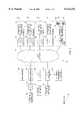
- FIG. 1is a high level block diagram illustrating a data over cable communication systems constructed utilizing the communication interface unit of the present invention
- FIG. 2is a block diagram illustrating the communication interface unit of the present invention in more detail
- FIG. 3is a block diagram illustrating the local loopback mode of the communications interface unit.
- FIG. 4is a block diagram illustrating the remote loopback mode of the communications interface unit.
- FIG. 1A high level block diagram illustrating a data over cable communication systems constructed utilizing the communication interface unit of the present invention is shown in FIG. 1.
- the communication interface unit (CUI) of the present inventionis capable of being connected to the CATV network at any point on the network.
- the communication interface unittransmits on an upstream channel in the range of 5 to 50 MHz and receives on a downstream channel in the range of 50 to 860 MHz.
- An example CATV based communication systemcomprising a head end facility 12, CATV network 14, a plurality of customer premises 22, 24, 26, 28 and the curb 32.
- each CUIis connected to some type of terminal equipment (network terminal).
- the terminal equipmentare the ⁇ consumers ⁇ in the network and may comprise, for example, a router in a local network communication application, a channel bank in a telephony application, a data multiplexor, a channel bank for voice and data in an application for a private network, any LAN/WAN networking or telecom equipment or other device communicating via E1/NI/DSX-1/V.35/Ethernet.
- the transverteris a conventional communication device that permits two communication interface units to communicate over the CATV network.
- the transverterfunctions to forward the data received on the upstream channel from a first CUI to the downstream channel of a second CUI. Similarly, the data received on the upstream channel of the second CUI is placed on the downstream channel of the first CUI.
- the CUI 20 in customer premises 26communicates with CUI 20 coupled to terminal equipment 34 in the head end via transverter 18.
- the transverterfunctions to cross swap the information on the upstream and downstream channels between the two CUIs.
- a third configurationcomprises the CUI 20 and terminal equipment coupled thereto in customer premises 28 coupled to CUI (Head End) 50 in the head end 12.
- the CUI (Head End) 50is a communication interface unit with a transmitter adapted to transmit on the downstream channel rather than the upstream channel in as CUI 20.
- the CUI (Head End) 50is adapted to receive on the upstream channel as opposed to transmit as in the CUI 20.
- a CUI (Curb) 30 coupled to terminal equipment 34communicates with CUI (Head End) 50 in the head end 12.
- the CUI (Curb) 30is a CUI adapted to interface with terminal equipment commonly located at the curb or street cabinet, e.g., channel bank equipment 34 supporting a plurality of voice telephone lines 36.
- a network management system 40is shown coupled to CUI (Head End) 50.
- the NMSis capable of communicating to any and all of the CUIs connected to the CATV network 14.
- the NMSis a PC based device that implements management functions such as conventional SNMP or other similar functioning management means for carrying out management activities.
- the NMSfunctions to facilitate remote control and supervisory operations over all the CUIs in the network.
- the communication interface unit of the present inventionwill now be described in more detail.
- a block diagram illustrating the communication interface unit in more detailis shown in FIG. 2.
- the CUIis a full duplex device relaying independent bi-directional communications.
- the received by the CUI from the terminalis coded, modulated and relayed onto the CATV network 14 (FIG. 1) in the form of an RF signal, directed either to the head end or the customer premises.
- the RF signal received from the CATV networkis demodulated, decoded and relayed as the original signal to the associated terminal.
- certain optional configurations of the CUIrequire the use of a transverter in the head end.
- the transverterfunctions to transvert, i.e., swap, the frequencies between the upstream and the downstream channels.
- the CUIfunctions to handle the signal received form the terminal and transmit it onto the CATV network.
- the signalis received from the terminal using the appropriate standard protocol and at the rate associated with the particular type of interface: E1 signals under the G.703 standard at a rate of 2.048 Mbps; T1 signals under the T1.403 standard at a rate of 1.544 Mbps; NI and DSX-1 signals under the T.403 standard at a rate of 1.544 Mbps; V.35 signals under the V.35 standard at a rate of N ⁇ 64 Kbps up to 2.048 Mbps and Ethernet 10BaseT signals using Manchester encoding/decoding at rates of 1.544 Mbps and 2.048 Mbps.
- the CUIperforms scrambling with the addition of redundant bits for error correction coding.
- the CUIperforms pulse shaping via a raised cosine filter having a roll off of approximately 20%.
- QPSK modulationis used in the CUI with RF modulation to a frequency within the range of 5 to 50 MHz.
- the CUIhandles the reception of the RF signal from the CATV network, demodulates and relays the signal as a signal in the appropriate format for the particular interface used.
- the RF signalis received within the frequency range of 50 to 860 MHz and mixed down to an IF frequency and filtered via a SAW filter in combination with a digital filter.
- the CUIperforms QPSK demodulation, error correction and descrambling followed by conversion of the signal to the appropriate interface.
- a forward error correcting (FEC) codefor example, any suitable conventional error correcting code such as Reed Solomon or a convolutional code, serves to improve communication reliability.
- FECforward error correcting
- the FEC algorithm used in the CUI for encoding and error correctionis based upon a convolution encoder and Viterbi encoder having a length of 7 stages at a standard 171 8 , and 133 8 , both well known in the art.
- other conventional error correction techniquescan be used such as Reed Solomon with 12% efficiency in accordance with the DVB standard as published in ETSI document ETS 300 429.
- the CPU 100 within the CUIperforms various functions such as supporting operation of the CUI via a local or remote PC, thus enabling activation of the communication interface from a remote control center; supporting various configuration functions; supporting status monitoring functions; and supporting diagnostic functions including loopbacks.
- the GMSK modem 109enables the establishment of a control channel to the network management system (NMS).
- the control channeloperates at a maximum rate of 38.4 Kbps using a minimum bandwidth of 50 KHz.
- the control channelis common to all communication interfaces units in the network. Polling is the regime used in the control channel to coordinate communication among all the CUIs, with each CUI being allocated a unique 4 byte address for identification purposes.
- the polling of all the CUIs on the control channelis coordinated by the NMS, which may be located, for example, at the head end.
- the CUI 20comprises a main modem having a transmit portion and a receive portion.
- the transmit portioncomprises transmitter interface 60, scrambler 62, FEC encoder 64, QPSK modulator 66, D/A converter 68 and LPF/RF level control 70.
- the transmitter interface 60functions to receive the signal output by the terminal equipment 34 and convert it to a TTL signal at a rate in accordance with the particular terminal interface in use.
- the receiver interface 92converts the TTL signal to a signal appropriate for the particular type of terminal equipment 34.
- the transmitter interface 60 and the receiver interface 92can be constructed on a small daughter PCB (not shown) having a suitable faceplate connected to the main PCB via a din Euro-connector.
- the daughter PCBcan be customized to the particular type of interface, i.e., E1, T1, etc.
- E1, T1, etc.can be used with the same main PCB.
- Each transmitter/receiver interfacecomprises identification means to permit the CPU 100 to identify the particular type of interface being used.
- the transmitter/receiver interfaceperforms signal validation by testing the signal in both direction.
- Signal faultsare reported to the controller 100 and include, for example, bipolar violations (BPV) status for E1/T1 signals, loss of signal (LOS) status, alarm indication signal (AIS) status.
- LOS statusfor V.35 signals.
- link integrityincluding the LAN Active Id and WAN Active Id, in addition to Tx/Rx activity for Ethernet. Note that in order to preserve complete communication path transparency, corrections are not performed on the signals transmitted from the terminal equipment (at the head end or the customer premises) in the event a fault is found. Synchronization is derived from the interfaces wherein the clock is extracted from the signal received from the terminal equipment.
- the transmitter interface 60 and the receive interface 92can be adapted to provide an E1 unbalanced interface.
- This interface signalhas a rate of 2.048 Mbps and is encoded in accordance with the CCITT G.703 standard.
- the impedanceis 75 ohms permitting connection of an unbalanced coaxial cable connector.
- Possible coding methodsinclude HDB3, AMI or B8ZS.
- the transmitter interface 60 and the receive interface 92can be adapted to provide an E1 balanced interface.
- This interface signalhas a rate of 2.048 Mbps and is encoded in accordance with the CCITT G.703 standard.
- the interfaceis a four wire interface having an impedance of 120 ohms permitting connection of a balanced connector such as DB9/DB15 or RJ48C.
- Possible coding methodsinclude HDB3, AMI or B8ZS.
- the transmitter interface 60 and the receive interface 92can be adapted to provide a T1 balanced network interface (NI).
- NIT1 balanced network interface
- This four wire interfacehas a rate of 1.544 Mbps and is encoded in accordance with ANSI T1.403 supporting three levels of LBO.
- the impedanceis 100 ohms permitting a connection of a balanced connector such as DB9/DB15 or RJ48C.
- Possible coding methodsinclude AMI or B8ZS.
- the transmitter interface 60 and the receive interface 92can be adapted to provide a T1 balanced cross connect interface.
- This four wire DS1 interfacehas a rate of 1.544 Mbps and is encoded in accordance with the ANSI T1.102 standard supporting five levels of pulse shaping.
- the interfacehas an impedance of 100 ohms permitting connection of a balanced connector such as DB9/DB15 or RJ48C. Possible coding methods include AMI or B8ZS.
- the transmitter interface 60 and the receive interface 92can be adapted to provide a standard V.35 interface including hand shake control signals suitable for interfacing with routers, data multiplexors and other terminal equipment at various data rates.
- the data rateis N ⁇ 64 Kbps where N ranges from 1 to 32, i.e., 64 Kbps to 2,048 Kbps.
- the interfacepermits synchronization to a centralized clock in addition to providing an external clock output for synchronization purposes.
- the transmitter interface 60 and the receive interface 92can also be adapted to provide an Ethernet interface.
- This interfacesupports a full duplex UTP or AUI LAN interface in accordance with the IEEE 802.3 Ethernet standard at a rate of up to 2.048 Mbps.
- This interfacefunctions as a self learning Ethernet bridge, learning MAC addresses present on the LAN and only forwarding frames destined for other LANs.
- the interfaceuses Manchester encoding and decoding and connects via a standard RJ45 (10BaseT) or D15 connector (10Base5).
- the output of the transmitter interface 60is coupled to the scrambler 62 which functions to insure randomness in the transmitted signal. This is particularly important for the transmission of information in the form of a cyclical series which would ordinarily create a spectrum of discrete lines. Scrambling provides for a relatively balanced distribution of the signal in the allocated frequency range.
- the scrambler 62preferably performs conventional self synchronized scrambling with 20 levels in accordance with the V.35 standard.
- the scrambling polynomial function usedis 1+X -3 +X -20 .
- the output of the scrambler 62is input to the FEC encoder 64.
- FECis needed since in some CATV networks, the carrier to noise ratio can be sufficiently low to reduce the BER to unacceptable levels.
- the error correction codeis preferably based on convolutional encoding with a redundancy of 12.5%, i.e., a rate of 7/8 or a redundancy of 25%, i.e. a rate of 3/4.
- an error correcting code compatible with the DVB standardi.e., Reed Solomon block code with 12% redundancy, can be used. Whichever code is used, the maximum delay in the voice path should be taken into account.
- the CUIcan be adapted to make FEC an option at the discretion of the user. The CUI can operate with or without FEC.
- the output of the FEC encoder 64is input to the QPSK modulator 66.
- the QPSK modulatorfunctions to perform differential encoding on the input data. Differential encoding is performed wherein the phase shift of each symbol is relative to the phase of the previous symbol and not to the absolute relative phase. This obviates the need to search for a permanent relative phase as is the case when non-differential encoding is used.
- the datais QPSK modulated onto a frequency wave carrier for transmission onto the upstream channel.
- the signalis filtered by a relatively sharp filter having a raised cosine response with a roll-off of 20%.
- the output of the modulator 66is a digital version of an RF signal in the range 5 to 50 MHz. Thus, the modulator 66 functions as a DDS.
- the output of the QPSK modulatoris then input to the D/A converter 68.
- the D/A converter 68converts the digital RF signal into an analog baseband RF signal.
- the analog signalis then fed to LPF/RF level control 70.
- the signalis low pass filtered by a filter having a suitable cutoff frequency for an input signal with a maximum frequency of 50 MHz.
- Block 70is also capable of adjusting the power level of the RF signal fed to the RF splitter 98.
- the transmission level of the RF output signalshould be controlled in order to compensate for variable conditions within the CATV network.
- the RF splitter 98functions to couple the signal between the transmitter/receiver and the CATV network.
- the RF splittercouples the RF signal from the CATV network to the RF tuner 80.
- the tunerdemodulates the signal to an IF frequency of, e.g., 32.9 MHz thus permitting the use of low cost standard SAW filters.
- the tuneris capable of demodulating input RF signals in the frequency range 50 to 860 MHz.
- the IF frequency signalis digitally sampled via A/D converter 82 with a sampling rate at least eight times greater than the symbol rate.
- the output of the A/D converter 82is then digitally filtered by a FIR filter block 84.
- the FIR filterfunctions to eliminate interference from adjacent channels.
- the digital signalAfter filtering, the digital signal is downconverted to baseband and demodulated via QPSK demodulator 86.
- the output of the QPSK demodulator 86is decoded via FEC decoder 88.
- descrambling of the signalis performed by descrambler 90, thus recovering the originally transmitted digital data.
- the CUIis adapted to be controlled both locally and remotely, both via a PC.
- Local controlis via an RS-232 interface input to the CUI.
- Remote controlis via the internal GMSK modem 109 that operates independently from the main modem.
- the channel provided by the GMSK modemprovides configuration operations, diagnostic and status monitoring.
- the GMSK modemoperates at a typical rate of 19.4 KHz using a 50 KHz bandwidth.
- the modemutilizes polling with each CUI identified by a unique 4 byte address. Any message sent or received by the NMS or CUI includes the source and destination address of the CUI or the NMS.
- the PC running the NMS applicationis connected to the CPU 100 of the CUI which is defined as a router in its configuration via RS-232 interface 102. Any messages sent to or received from the other CUIs are routed through the GMSK modem such that all other CUIs communicate through the CUI configured as a router. Note that only one CUI in a network system can be designated the router
- RS-485 interface 105 coupled to CPU 100can be used to tie a plurality of CUI's together.
- one designated CUIis connected to the NMS via the RS-232 interface 102.
- Other CUI's in the same locationcan be connected together via an RS-485 network bus.
- the CUI designated as the routercommunicates with other CUIs on the CATV network via GMSK modem.
- the Guassian minimum shift keying (GMSK) modem 109comprises a GMSK modulator 110 which receives data to be transmitted from the CPU 100.
- the modulated outputis upconverted to a transmit frequency within the range of 5 to 50 MHz by the RF output section 114.
- the RF outputis input to the RF splitter 98 which places the control channel RF signal onto the CATV network.
- the GMSK modem 109also comprises an RF input section 116 which receives the control channel signal via the RF splitter 98 and downconverts it to baseband.
- the control channel receive signalranges in frequency from 50 and 860 MHz.
- the baseband output of the RF input section 116is input to the GMSK demodulator 112 which outputs demodulated data to the CPU 100.
- the operation of the CUIis determined by various parameters loaded into it via the PC and stored in non-volatile memory incorporated within the CUI. Parameters such as configuration parameters, can be read by the PC.
- the configuration parametersinclude, but are not limited to, the parameters listed in the following table.
- the CUIfunctions to monitor the status of various different points during its operation.
- the CUIreports the status of these points to the NMS 40 (FIG. 2) whenever the NMS makes a request for status.
- the various points monitored for status purposesinclude, but are not limited to, the following:
- faults in the signal received from the terminal equipmentfor E1 and T1 interfaces, the faults are LOS. AIS and BPV; for the V.35 interface, the indications are LOS and DTR; for an Ethernet interface, the indications are Link integrity and WAN active.
- Faults in an internal component of the CUIi.e., faults in hardware components which cause faulty operation of the CUI.
- the status of these componentscan be determined by activation of a BIT function.
- the CUI of the present inventionalso incorporates diagnostic functionality, which will now be described in more detail.
- diagnostic operationsare provided in order to isolate faulty components on the link in addition to detecting the nature of the fault.
- the linkcomprises a first CUI in a first location, a second CUI in a second location, the CATV network or one of the two terminal equipments.
- the diagnostic operations that can be performed to isolate faulty components on the linkinclude, but are not limited to, the following:
- Activation of a random series of transmissions and associated receptionThis can be used for error rate testing and reporting. Commands are provided for the activation and deactivation of this series of transmissions.
- the seriescomprises pseudo random number (PN) sequences with code of (10,3) and (23,18).
- the CUIoptionally comprises a watchdog mechanism that functions to reset the CUI in the event it hangs up.
- a watchdog mechanismthat functions to reset the CUI in the event it hangs up.
- a lock diagram illustrating the local loopback mode of the communications interface unitis shown in FIG. 3.
- the CUIis capable of performing local loopback diagnostics.
- Two CUIs 122, 124are shown coupled to CATV network 14.
- Terminal equipment 120is coupled to CUI 122 and terminal equipment 126 is coupled to CUI 124.
- the CUIperforms local loopback on the path at the nearest terminal equipment to which it is connected.
- the data received from the terminal equipment by the CUIis returned back to the terminal equipment.
- the CUItransmits RF onto the CATV network in order to maintain the channel transmission.
- the CUIfunctions to relay the input signal from the terminal equipment back as an output signal to the terminal equipment itself.
- Tx SIGNALthe data sent by terminal equipment 126 denoted by Tx SIGNAL is relayed back by the CUI 124 to the terminal equipment 126 as Rx SIGNAL.
- the data sent by terminal equipment 120 denoted by Tx SIGNALis relayed back by the CUI 122 to the terminal equipment 120 as Rx SIGNAL.
- FIG. 4A block diagram illustrating the remote loopback mode of the communications interface unit is shown in FIG. 4.
- the CUIis capable of performing remote loopback diagnostics.
- Two CUIs 132, 134are shown coupled to CATV network 14.
- Terminal equipment 130is coupled to CUI 132 and terminal equipment 136 is coupled to CUI 134.
- the CUIperforms remote loopback on the digital path towards the far end CUI connected to terminal equipment.
- the far end CUIperforms digital loopback toward the near end CUI.
- the data transmitted by the near end terminal equipmentis returned by the far end via the CATV network.
- CUI 132is in remote loopback on one side and local loopback on the other side.
- Data sent from terminal equipment 130 denoted Tx SIGNALis returned to it via the CUI 132 as the signal denoted Rx SIGNAL.
- Data sent from terminal equipment 136 denoted Tx SIGNALis transmitted by CUI 134 to CUI 132 via CATV network 14.
- CUI 132in digital loopback, transmits the received signal back to the CUI 143 over the CATV network.
- the signal Rx SIGNALis returned to the terminal equipment 136, completing the remote loopback path.
Landscapes
- Engineering & Computer Science (AREA)
- Signal Processing (AREA)
- Multimedia (AREA)
- Computer Networks & Wireless Communication (AREA)
- Two-Way Televisions, Distribution Of Moving Picture Or The Like (AREA)
Abstract
Description
______________________________________ Notation Definition ______________________________________ AAL5 ATM Adaptation Layer 5 AIS Alarm Indication Signal AM Amplitude Modulation AMI Alternate Mark Inversion ARP Address Resolution Protocol ATM Asynchronous Transfer Mode B8ZS Bipolar 8 Zero Substitution BER Bit Error Rate BIT Built In Test BPV Bipolar Violation CATV Community Antenna Television CDM Cable Data Modem CGW CATV Gateway CUI Communication Interface Unit CPU Central Processing Unit CRC Cyclic Redundancy Code DDS Direct Digital Synthesizer DHCP Dynamic Host Configuration Protocol DVB Digital Video Broadcast FEC Forward Error Correction FIR Finite Impulse Response HDB3 High Density Bipolar of order 3 HDLC Data Link Control HES Head-end Subsystem IF Intermediate Frequency IP Internet Protocol ISP Internet Service Provider LAN Local Area Network LBO Line Build Out LOS Loss of Signal LSB Least Significant Bit MAC Media Access Control MMI Man Machine Interface MPEG Motion Picture Engineering Group MUX Multiplexor NI Network Interface NIC Network Interface Controller NMS Network Management System NRZ Non Return to Zero PC Personal Computer PCB Printed Circuit Board PN Pseudo Random Number PSTN Public Switched Telephone Network QAM Quadrature Amplitude Modulation QPSK Quadrature Phase Shift Keying RF Radio Frequency SAR Segmentation and Reassembly SAW Surface Acoustic Wave SNMP Simple Network Management Protocol SRI Slot Reception Indicator TDMA Time Division Multiple Access TTL Transistor Transistor Logic UCU Upstream Control Unit UDU Upstream Data Unit VC Virtual Circuit VPN Virtual Private Network WAN Wide Area Network ______________________________________
______________________________________ Parameter Description/Comment ______________________________________ Main receive frequency between 50 and 860 MHz Main transmit frequency between 5 and 50 MHz Control channel receive frequency between 50 and 860 MHz Control channel transmit frequency between 5 and 50 MHz Interface type definition E1; T1 NI/CI; T1 DSX-1; V.35; Ethernet Signal encoding method for E1: HD3B, AMI or B8ZS; for T1: AMI or B8ZS LBO attenuation level type A, B, C for A: 0 dB; for B: 7.5 dB; for C: 15.0 dB Line lengths between CUI and for T1 DSX-1: 0 to 133 ft; 133 to 266 DSX-1 cross connect ft; 266 to 399 ft; 399 to 533 ft; 533 to 655 ft Operation rate for E1: 2.048 Mbps; for T1: 1.544 Mbps; for Ethernet: 1.544 or 2.048 Mbps; for V.35: Nx64 Kbps where N equals 1 to 32.Error correction handling 1. no FEC 2. FEC with 7/8 rate 3. FEC with 3/4 rate Identification number of the CUI unique 4 byte address CUI data link transmission level dynamic range is 24 dB within 1 dB steps CUI GMSK transmission level dynamic range is 20 dB in 1 dB steps Data link tuner calibration correction of the IF frequency deviation of the RF tuner 80 (FIG. 2) CUI software version number read only parameter CUI hardware version number read only parameter ______________________________________
Claims (19)
Priority Applications (1)
| Application Number | Priority Date | Filing Date | Title |
|---|---|---|---|
| US09/013,919US6112232A (en) | 1998-01-27 | 1998-01-27 | Data communication device for CATV networks |
Applications Claiming Priority (1)
| Application Number | Priority Date | Filing Date | Title |
|---|---|---|---|
| US09/013,919US6112232A (en) | 1998-01-27 | 1998-01-27 | Data communication device for CATV networks |
Publications (1)
| Publication Number | Publication Date |
|---|---|
| US6112232Atrue US6112232A (en) | 2000-08-29 |
Family
ID=21762511
Family Applications (1)
| Application Number | Title | Priority Date | Filing Date |
|---|---|---|---|
| US09/013,919Expired - Fee RelatedUS6112232A (en) | 1998-01-27 | 1998-01-27 | Data communication device for CATV networks |
Country Status (1)
| Country | Link |
|---|---|
| US (1) | US6112232A (en) |
Cited By (59)
| Publication number | Priority date | Publication date | Assignee | Title |
|---|---|---|---|---|
| WO2001056181A1 (en)* | 2000-01-26 | 2001-08-02 | Vyyo, Ltd. | Power inserter configuration for wireless modems |
| US6298246B1 (en)* | 1997-11-20 | 2001-10-02 | Airspan Networks, Inc. | Subscriber terminal and method for passing control signals between a first and second signal processing units |
| WO2001093475A1 (en)* | 2000-05-25 | 2001-12-06 | Passover, Inc. | Mobile radio service over catv network |
| US20010051512A1 (en)* | 2000-01-26 | 2001-12-13 | Vyyo Ltd. | Redundancy scheme for the radio frequency front end of a broadband wireless hub |
| US20020019983A1 (en)* | 2000-06-05 | 2002-02-14 | Emsley Brett W. | Testing instrument |
| US20020024975A1 (en)* | 2000-03-14 | 2002-02-28 | Hillel Hendler | Communication receiver with signal processing for beam forming and antenna diversity |
| US20020052205A1 (en)* | 2000-01-26 | 2002-05-02 | Vyyo, Ltd. | Quality of service scheduling scheme for a broadband wireless access system |
| US20020056132A1 (en)* | 2000-01-26 | 2002-05-09 | Vyyo Ltd. | Distributed processing for optimal QOS in a broadband access system |
| US6389030B1 (en)* | 1998-08-21 | 2002-05-14 | Adc Telecommunications, Inc. | Internet access over a ring network |
| US6453473B1 (en)* | 1998-09-15 | 2002-09-17 | John C. Watson, Jr. | Access device and system for managing television and data communications through a cable television network |
| US20020144280A1 (en)* | 2001-03-27 | 2002-10-03 | Syuuji Matsuura | Cable modem tuner |
| US20020159511A1 (en)* | 2000-01-26 | 2002-10-31 | Vyyo Ltd. | Transverter control mechanism for a wireless modem in a broadband access system |
| WO2002089373A1 (en)* | 2001-04-13 | 2002-11-07 | Passover Inc. | Third generation (3g) mobile service over catv network |
| US6498821B2 (en) | 2000-01-26 | 2002-12-24 | Vyyo, Ltd. | Space diversity method and system for broadband wireless access |
| US6557031B1 (en)* | 1997-09-05 | 2003-04-29 | Hitachi, Ltd. | Transport protocol conversion method and protocol conversion equipment |
| US6570880B1 (en)* | 1998-08-21 | 2003-05-27 | Adc Telecommunications, Inc. | Control data over a ring network |
| US20030115591A1 (en)* | 2001-12-17 | 2003-06-19 | Automated Media Services, Inc. | System and method for verifying content displayed on an electronic visual display |
| US20030202612A1 (en)* | 2001-12-18 | 2003-10-30 | Bijit Halder | Method and system for rate enhanced SHDSL |
| US6687286B1 (en)* | 1999-12-17 | 2004-02-03 | Agere Systems, Inc. | Programmable transmitter circuit for coupling to an ethernet or fast ethernet |
| US6690655B1 (en)* | 2000-10-19 | 2004-02-10 | Motorola, Inc. | Low-powered communication system and method of operation |
| US6760391B1 (en)* | 1999-09-14 | 2004-07-06 | Nortel Networks Limited | Method and apparatus for line rate control in a digital communications system |
| US20040166833A1 (en)* | 2001-03-02 | 2004-08-26 | Dan Shklarsky | Mobile radio service over catv network |
| US20050060362A1 (en)* | 2002-10-17 | 2005-03-17 | Wolinsky Robert I. | System and method for editing existing footage to generate and distribute advertising content to retail locations |
| US20050183130A1 (en)* | 2004-02-12 | 2005-08-18 | Sadja Aran L. | Cable diagnostic and monitoring system |
| US6940833B2 (en) | 2000-01-26 | 2005-09-06 | Vyyo Ltd. | Two-dimensional scheduling scheme for a broadband wireless access system |
| US6941576B2 (en) | 1999-04-12 | 2005-09-06 | Texas Instruments Incorporated | System and methods for home network communications |
| US6987754B2 (en) | 2000-03-07 | 2006-01-17 | Menashe Shahar | Adaptive downstream modulation scheme for broadband wireless access systems |
| US20060104207A1 (en)* | 2004-11-17 | 2006-05-18 | Tollgrade Communications, Inc. | Apparatus and method of remotely enabling a special mode of operation of an endpoint in a VoIP network |
| US7058075B1 (en)* | 1999-06-15 | 2006-06-06 | Cisco Technology, Inc. | Self-configuring interface for communication protocols |
| US7123650B2 (en) | 2000-01-26 | 2006-10-17 | Vyyo, Inc. | Offset carrier frequency correction in a two-way broadband wireless access system |
| US20060277179A1 (en)* | 2005-06-03 | 2006-12-07 | Bailey Michael P | Method for communication between computing devices using coded values |
| WO2007080229A1 (en)* | 2006-01-13 | 2007-07-19 | Teleste Oyj | Data link management in coaxial media |
| US7275113B1 (en)* | 1999-05-27 | 2007-09-25 | 3 Com Corporation | Dynamic network address configuration system and method |
| US7359434B2 (en) | 2000-01-26 | 2008-04-15 | Vyyo Ltd. | Programmable PHY for broadband wireless access systems |
| US20080109854A1 (en)* | 2006-11-06 | 2008-05-08 | Casavant Scott D | Satellite television ip bitstream generator receiving unit |
| US20080120655A1 (en)* | 2006-11-22 | 2008-05-22 | The Directv Group, Inc. | Integrated satellite master antenna television unit |
| US20080247401A1 (en)* | 2007-04-06 | 2008-10-09 | Texas Instruments Incorporated | Remote Access to Home Communication Services |
| US20090141640A1 (en)* | 2007-11-29 | 2009-06-04 | Adc Dsl Systems, Inc. | Port failure communication in cross-connect applications |
| US20100023994A1 (en)* | 2008-07-25 | 2010-01-28 | At & T Intellectual Property I, L.P. | Network Interface Devices |
| US20100064078A1 (en)* | 2008-08-15 | 2010-03-11 | Powell Thomas J | Wireless communication between testing instrument and network |
| US7742950B2 (en) | 2001-10-17 | 2010-06-22 | Automated Media Services, Inc. | System and method for providing for out-of-home advertising utilizing a satellite network |
| US20110141921A1 (en)* | 2009-12-14 | 2011-06-16 | At&T Intellectual Property I, L.P. | Identifying Network Performance Alert Conditions |
| US8132216B1 (en)* | 2008-11-07 | 2012-03-06 | The Directv Group, Inc. | Method and system for controlling a multi-terminal system |
| US8270430B2 (en) | 1998-07-28 | 2012-09-18 | Mosaid Technologies Incorporated | Local area network of serial intelligent cells |
| US20130061276A1 (en)* | 2011-09-06 | 2013-03-07 | Comcast Cable Communications, Llc | Transmitting Signals Using Directional Diversity Over a Network |
| US8582598B2 (en) | 1999-07-07 | 2013-11-12 | Mosaid Technologies Incorporated | Local area network for distributing data communication, sensing and control signals |
| US8595770B2 (en) | 2011-10-31 | 2013-11-26 | The Directv Group, Inc. | Aggregated content distribution system and method for operating the same |
| US8621530B1 (en) | 2011-10-31 | 2013-12-31 | The Directv Group, Inc. | Method and system for controlling user devices in an aggregated content distribution system |
| US8743790B2 (en) | 2009-08-24 | 2014-06-03 | At&T Intellectual Property I, L.P. | Residential gateway |
| US8856843B1 (en) | 2011-10-31 | 2014-10-07 | The Directv Group, Inc. | Method and system for adding local channels and program guide data at a user receiving device in an aggregated content distribution system |
| US8873575B2 (en) | 2000-04-19 | 2014-10-28 | Conversant Intellectual Property Management Incorporated | Network combining wired and non-wired segments |
| US9042237B2 (en) | 2009-12-14 | 2015-05-26 | At&T Intellectual Property I, L.P. | Identifying network performance alert conditions |
| US9942618B2 (en) | 2007-10-31 | 2018-04-10 | The Directv Group, Inc. | SMATV headend using IP transport stream input and method for operating the same |
| US9992525B1 (en) | 2008-09-15 | 2018-06-05 | The Directv Group, Inc. | Method and system for inserting local channel insertion in a multi-terminal system |
| US10021437B1 (en) | 2008-09-15 | 2018-07-10 | The Directv Group, Inc. | Method and system for discontinuing a channel stream in a multi-terminal system |
| US10986165B2 (en) | 2004-01-13 | 2021-04-20 | May Patents Ltd. | Information device |
| US11057615B2 (en) | 2018-09-18 | 2021-07-06 | Antronix Inc. | Inventory tracking in cable TV system |
| US20210344873A1 (en)* | 2016-10-03 | 2021-11-04 | Enseo, Llc | Distribution Element for a Self-Calibrating RF Network and System and Method for Use of the Same |
| US20210377064A1 (en)* | 2020-05-19 | 2021-12-02 | Arris Enterprises Llc | Systems and methods for upstream and downstream catv plant capacity expansion |
Citations (15)
| Publication number | Priority date | Publication date | Assignee | Title |
|---|---|---|---|---|
| US5347304A (en)* | 1991-09-10 | 1994-09-13 | Hybrid Networks, Inc. | Remote link adapter for use in TV broadcast data transmission system |
| US5410535A (en)* | 1992-07-02 | 1995-04-25 | Digital Equipment Corporation | Automatic selection of an interface for ethernet stations |
| US5412352A (en)* | 1994-04-18 | 1995-05-02 | Stanford Telecommunications, Inc. | Modulator having direct digital synthesis for broadband RF transmission |
| US5481562A (en)* | 1989-11-03 | 1996-01-02 | Microcom Systems, Inc. | Multi-mode modem and data transmission method |
| US5488412A (en)* | 1994-03-31 | 1996-01-30 | At&T Corp. | Customer premises equipment receives high-speed downstream data over a cable television system and transmits lower speed upstream signaling on a separate channel |
| US5499046A (en)* | 1994-05-23 | 1996-03-12 | Cable Services Technologies, Inc. | CATV distribution system with each channel having its own remote scheduler |
| US5563908A (en)* | 1993-02-18 | 1996-10-08 | Fujitsu Limited | Modulator and demodulator apparatus |
| US5577087A (en)* | 1991-10-31 | 1996-11-19 | Nec Corporation | Variable modulation communication method and system |
| US5592540A (en)* | 1993-05-28 | 1997-01-07 | U S West Advanced Technologies, Inc. | Method and apparatus for selectively delivering telephony signals on a hybrid coaxial cable network |
| US5642155A (en)* | 1994-09-14 | 1997-06-24 | Cheng; Alexander L. | Method and apparatus for supporting two-way telecommunications on CATV networks |
| US5675732A (en)* | 1995-05-08 | 1997-10-07 | Lucent Technologies Inc. | Dynamic channel assignment for TCP/IP data transmitted via cable television channels by managing the channels as a single sub network |
| US5719872A (en)* | 1993-09-17 | 1998-02-17 | Scientific-Atlanta, Inc. | Reverse path allocation and contention resolution scheme for a broadband communications system |
| US5805636A (en)* | 1996-10-01 | 1998-09-08 | Intel Corporation | Method and apparatus for simultaneous voice, data, and video communication in a computer system |
| US5825829A (en)* | 1995-06-30 | 1998-10-20 | Scientific-Atlanta, Inc. | Modulator for a broadband communications system |
| US5896414A (en)* | 1996-09-17 | 1999-04-20 | Sarnoff Corporation | Method and apparatus for providing control channel communications for an information distribution system |
- 1998
- 1998-01-27USUS09/013,919patent/US6112232A/ennot_activeExpired - Fee Related
Patent Citations (15)
| Publication number | Priority date | Publication date | Assignee | Title |
|---|---|---|---|---|
| US5481562A (en)* | 1989-11-03 | 1996-01-02 | Microcom Systems, Inc. | Multi-mode modem and data transmission method |
| US5347304A (en)* | 1991-09-10 | 1994-09-13 | Hybrid Networks, Inc. | Remote link adapter for use in TV broadcast data transmission system |
| US5577087A (en)* | 1991-10-31 | 1996-11-19 | Nec Corporation | Variable modulation communication method and system |
| US5410535A (en)* | 1992-07-02 | 1995-04-25 | Digital Equipment Corporation | Automatic selection of an interface for ethernet stations |
| US5563908A (en)* | 1993-02-18 | 1996-10-08 | Fujitsu Limited | Modulator and demodulator apparatus |
| US5592540A (en)* | 1993-05-28 | 1997-01-07 | U S West Advanced Technologies, Inc. | Method and apparatus for selectively delivering telephony signals on a hybrid coaxial cable network |
| US5719872A (en)* | 1993-09-17 | 1998-02-17 | Scientific-Atlanta, Inc. | Reverse path allocation and contention resolution scheme for a broadband communications system |
| US5488412A (en)* | 1994-03-31 | 1996-01-30 | At&T Corp. | Customer premises equipment receives high-speed downstream data over a cable television system and transmits lower speed upstream signaling on a separate channel |
| US5412352A (en)* | 1994-04-18 | 1995-05-02 | Stanford Telecommunications, Inc. | Modulator having direct digital synthesis for broadband RF transmission |
| US5499046A (en)* | 1994-05-23 | 1996-03-12 | Cable Services Technologies, Inc. | CATV distribution system with each channel having its own remote scheduler |
| US5642155A (en)* | 1994-09-14 | 1997-06-24 | Cheng; Alexander L. | Method and apparatus for supporting two-way telecommunications on CATV networks |
| US5675732A (en)* | 1995-05-08 | 1997-10-07 | Lucent Technologies Inc. | Dynamic channel assignment for TCP/IP data transmitted via cable television channels by managing the channels as a single sub network |
| US5825829A (en)* | 1995-06-30 | 1998-10-20 | Scientific-Atlanta, Inc. | Modulator for a broadband communications system |
| US5896414A (en)* | 1996-09-17 | 1999-04-20 | Sarnoff Corporation | Method and apparatus for providing control channel communications for an information distribution system |
| US5805636A (en)* | 1996-10-01 | 1998-09-08 | Intel Corporation | Method and apparatus for simultaneous voice, data, and video communication in a computer system |
Cited By (103)
| Publication number | Priority date | Publication date | Assignee | Title |
|---|---|---|---|---|
| US6557031B1 (en)* | 1997-09-05 | 2003-04-29 | Hitachi, Ltd. | Transport protocol conversion method and protocol conversion equipment |
| US6298246B1 (en)* | 1997-11-20 | 2001-10-02 | Airspan Networks, Inc. | Subscriber terminal and method for passing control signals between a first and second signal processing units |
| US8885660B2 (en) | 1998-07-28 | 2014-11-11 | Conversant Intellectual Property Management Incorporated | Local area network of serial intelligent cells |
| US8325636B2 (en) | 1998-07-28 | 2012-12-04 | Mosaid Technologies Incorporated | Local area network of serial intelligent cells |
| US8867523B2 (en) | 1998-07-28 | 2014-10-21 | Conversant Intellectual Property Management Incorporated | Local area network of serial intelligent cells |
| US8885659B2 (en) | 1998-07-28 | 2014-11-11 | Conversant Intellectual Property Management Incorporated | Local area network of serial intelligent cells |
| US8270430B2 (en) | 1998-07-28 | 2012-09-18 | Mosaid Technologies Incorporated | Local area network of serial intelligent cells |
| US8908673B2 (en) | 1998-07-28 | 2014-12-09 | Conversant Intellectual Property Management Incorporated | Local area network of serial intelligent cells |
| US6570880B1 (en)* | 1998-08-21 | 2003-05-27 | Adc Telecommunications, Inc. | Control data over a ring network |
| US6389030B1 (en)* | 1998-08-21 | 2002-05-14 | Adc Telecommunications, Inc. | Internet access over a ring network |
| US6453473B1 (en)* | 1998-09-15 | 2002-09-17 | John C. Watson, Jr. | Access device and system for managing television and data communications through a cable television network |
| US6941576B2 (en) | 1999-04-12 | 2005-09-06 | Texas Instruments Incorporated | System and methods for home network communications |
| US7127734B1 (en) | 1999-04-12 | 2006-10-24 | Texas Instruments Incorporated | System and methods for home network communications |
| US7275113B1 (en)* | 1999-05-27 | 2007-09-25 | 3 Com Corporation | Dynamic network address configuration system and method |
| US7058075B1 (en)* | 1999-06-15 | 2006-06-06 | Cisco Technology, Inc. | Self-configuring interface for communication protocols |
| US8582598B2 (en) | 1999-07-07 | 2013-11-12 | Mosaid Technologies Incorporated | Local area network for distributing data communication, sensing and control signals |
| US6760391B1 (en)* | 1999-09-14 | 2004-07-06 | Nortel Networks Limited | Method and apparatus for line rate control in a digital communications system |
| US6687286B1 (en)* | 1999-12-17 | 2004-02-03 | Agere Systems, Inc. | Programmable transmitter circuit for coupling to an ethernet or fast ethernet |
| US6941119B2 (en) | 2000-01-26 | 2005-09-06 | Vyyo Ltd. | Redundancy scheme for the radio frequency front end of a broadband wireless hub |
| US7149188B2 (en) | 2000-01-26 | 2006-12-12 | Vyyo, Inc. | Distributed processing for optimal QOS in a broadband access system |
| US20010036841A1 (en)* | 2000-01-26 | 2001-11-01 | Vyyo Ltd. | Power inserter configuration for wireless modems |
| US20010051512A1 (en)* | 2000-01-26 | 2001-12-13 | Vyyo Ltd. | Redundancy scheme for the radio frequency front end of a broadband wireless hub |
| WO2001056181A1 (en)* | 2000-01-26 | 2001-08-02 | Vyyo, Ltd. | Power inserter configuration for wireless modems |
| US20020052205A1 (en)* | 2000-01-26 | 2002-05-02 | Vyyo, Ltd. | Quality of service scheduling scheme for a broadband wireless access system |
| US7359434B2 (en) | 2000-01-26 | 2008-04-15 | Vyyo Ltd. | Programmable PHY for broadband wireless access systems |
| US20020056132A1 (en)* | 2000-01-26 | 2002-05-09 | Vyyo Ltd. | Distributed processing for optimal QOS in a broadband access system |
| US6856786B2 (en) | 2000-01-26 | 2005-02-15 | Vyyo Ltd. | Quality of service scheduling scheme for a broadband wireless access system |
| US20020159511A1 (en)* | 2000-01-26 | 2002-10-31 | Vyyo Ltd. | Transverter control mechanism for a wireless modem in a broadband access system |
| US6876834B2 (en) | 2000-01-26 | 2005-04-05 | Vyyo, Ltd. | Power inserter configuration for wireless modems |
| US7123650B2 (en) | 2000-01-26 | 2006-10-17 | Vyyo, Inc. | Offset carrier frequency correction in a two-way broadband wireless access system |
| US6940833B2 (en) | 2000-01-26 | 2005-09-06 | Vyyo Ltd. | Two-dimensional scheduling scheme for a broadband wireless access system |
| US7027776B2 (en) | 2000-01-26 | 2006-04-11 | Vyyo, Inc. | Transverter control mechanism for a wireless modem in a broadband access system |
| US6498821B2 (en) | 2000-01-26 | 2002-12-24 | Vyyo, Ltd. | Space diversity method and system for broadband wireless access |
| US6987754B2 (en) | 2000-03-07 | 2006-01-17 | Menashe Shahar | Adaptive downstream modulation scheme for broadband wireless access systems |
| US20020024975A1 (en)* | 2000-03-14 | 2002-02-28 | Hillel Hendler | Communication receiver with signal processing for beam forming and antenna diversity |
| US7298715B2 (en) | 2000-03-14 | 2007-11-20 | Vyyo Ltd | Communication receiver with signal processing for beam forming and antenna diversity |
| US8873575B2 (en) | 2000-04-19 | 2014-10-28 | Conversant Intellectual Property Management Incorporated | Network combining wired and non-wired segments |
| US8982904B2 (en) | 2000-04-19 | 2015-03-17 | Conversant Intellectual Property Management Inc. | Network combining wired and non-wired segments |
| US8873586B2 (en) | 2000-04-19 | 2014-10-28 | Conversant Intellectual Property Management Incorporated | Network combining wired and non-wired segments |
| WO2001093475A1 (en)* | 2000-05-25 | 2001-12-06 | Passover, Inc. | Mobile radio service over catv network |
| US20020019983A1 (en)* | 2000-06-05 | 2002-02-14 | Emsley Brett W. | Testing instrument |
| US6690655B1 (en)* | 2000-10-19 | 2004-02-10 | Motorola, Inc. | Low-powered communication system and method of operation |
| US20040166833A1 (en)* | 2001-03-02 | 2004-08-26 | Dan Shklarsky | Mobile radio service over catv network |
| US20020144280A1 (en)* | 2001-03-27 | 2002-10-03 | Syuuji Matsuura | Cable modem tuner |
| WO2002089373A1 (en)* | 2001-04-13 | 2002-11-07 | Passover Inc. | Third generation (3g) mobile service over catv network |
| US7912759B2 (en) | 2001-10-17 | 2011-03-22 | Automated Media Services, Inc. | Method for providing a retailer with out-of-home advertising capabilities |
| US7742950B2 (en) | 2001-10-17 | 2010-06-22 | Automated Media Services, Inc. | System and method for providing for out-of-home advertising utilizing a satellite network |
| US8315913B2 (en) | 2001-10-17 | 2012-11-20 | Automated Media Services, Inc. | System and method for determining physical location of electronic display devices in a retail establishment |
| US7614065B2 (en) | 2001-12-17 | 2009-11-03 | Automated Media Services, Inc. | System and method for verifying content displayed on an electronic visual display |
| US20030115591A1 (en)* | 2001-12-17 | 2003-06-19 | Automated Media Services, Inc. | System and method for verifying content displayed on an electronic visual display |
| US7937723B2 (en) | 2001-12-17 | 2011-05-03 | Automated Media Services, Inc. | System and method for verifying content displayed on an electronic visual display by measuring an operational parameter of the electronic visual display while displaying the content |
| US7076514B2 (en) | 2001-12-18 | 2006-07-11 | Conexant, Inc. | Method and system for computing pre-equalizer coefficients |
| US20040021595A1 (en)* | 2001-12-18 | 2004-02-05 | Erdogan Alper Tunga | Method and system for implementing a sigma delta analog-to-digital converter |
| US20030235245A1 (en)* | 2001-12-18 | 2003-12-25 | Erdogan Alper Tunga | Method and system for computing pre-equalizer coefficients |
| US20030202612A1 (en)* | 2001-12-18 | 2003-10-30 | Bijit Halder | Method and system for rate enhanced SHDSL |
| US6788236B2 (en) | 2001-12-18 | 2004-09-07 | Globespanvirata, Inc. | Method and system for implementing a sigma delta analog-to-digital converter |
| US20050060362A1 (en)* | 2002-10-17 | 2005-03-17 | Wolinsky Robert I. | System and method for editing existing footage to generate and distribute advertising content to retail locations |
| US7613630B2 (en) | 2002-10-17 | 2009-11-03 | Automated Media Services, Inc. | System and method for editing existing footage to generate and distribute advertising content to retail locations |
| US10986165B2 (en) | 2004-01-13 | 2021-04-20 | May Patents Ltd. | Information device |
| US20050183130A1 (en)* | 2004-02-12 | 2005-08-18 | Sadja Aran L. | Cable diagnostic and monitoring system |
| US20110099570A1 (en)* | 2004-02-12 | 2011-04-28 | Aran London Sadja | Cable Diagnostic and Monitoring System |
| US8413200B2 (en) | 2004-02-12 | 2013-04-02 | Sony Corporation | Cable television viewing statistics |
| US8352995B2 (en) | 2004-02-12 | 2013-01-08 | Sony Corporation | Polling cable diagnostic and monitoring system that aggregates responses from multiple terminals |
| US20110099569A1 (en)* | 2004-02-12 | 2011-04-28 | Aran London Sadja | Cable Diagnostic and Monitoring System |
| US7895632B2 (en) | 2004-02-12 | 2011-02-22 | Sony Corporation | Cable diagnostic and monitoring system |
| US7567520B2 (en)* | 2004-11-17 | 2009-07-28 | Tollgrade Communications, Inc. | Apparatus and method of remotely enabling a special mode of operation of an endpoint in a VoIP network |
| US20060104207A1 (en)* | 2004-11-17 | 2006-05-18 | Tollgrade Communications, Inc. | Apparatus and method of remotely enabling a special mode of operation of an endpoint in a VoIP network |
| US8103880B2 (en)* | 2005-06-03 | 2012-01-24 | Adobe Systems Incorporated | Method for communication between computing devices using coded values |
| US20060277179A1 (en)* | 2005-06-03 | 2006-12-07 | Bailey Michael P | Method for communication between computing devices using coded values |
| WO2007080229A1 (en)* | 2006-01-13 | 2007-07-19 | Teleste Oyj | Data link management in coaxial media |
| US8719875B2 (en) | 2006-11-06 | 2014-05-06 | The Directv Group, Inc. | Satellite television IP bitstream generator receiving unit |
| US20080109854A1 (en)* | 2006-11-06 | 2008-05-08 | Casavant Scott D | Satellite television ip bitstream generator receiving unit |
| US20080120655A1 (en)* | 2006-11-22 | 2008-05-22 | The Directv Group, Inc. | Integrated satellite master antenna television unit |
| US20080247401A1 (en)* | 2007-04-06 | 2008-10-09 | Texas Instruments Incorporated | Remote Access to Home Communication Services |
| US9942618B2 (en) | 2007-10-31 | 2018-04-10 | The Directv Group, Inc. | SMATV headend using IP transport stream input and method for operating the same |
| US8358584B2 (en)* | 2007-11-29 | 2013-01-22 | Adc Dsl Systems, Inc. | Port failure communication in cross-connect applications |
| TWI467942B (en)* | 2007-11-29 | 2015-01-01 | Adc Dsl Sys Inc | Port failure communication in cross-connect applications |
| US20090141640A1 (en)* | 2007-11-29 | 2009-06-04 | Adc Dsl Systems, Inc. | Port failure communication in cross-connect applications |
| US20100023994A1 (en)* | 2008-07-25 | 2010-01-28 | At & T Intellectual Property I, L.P. | Network Interface Devices |
| US8887220B2 (en)* | 2008-07-25 | 2014-11-11 | At&T Intellectual Property I, L.P. | Network interface devices |
| US20100064078A1 (en)* | 2008-08-15 | 2010-03-11 | Powell Thomas J | Wireless communication between testing instrument and network |
| US10021437B1 (en) | 2008-09-15 | 2018-07-10 | The Directv Group, Inc. | Method and system for discontinuing a channel stream in a multi-terminal system |
| US9992525B1 (en) | 2008-09-15 | 2018-06-05 | The Directv Group, Inc. | Method and system for inserting local channel insertion in a multi-terminal system |
| US8132216B1 (en)* | 2008-11-07 | 2012-03-06 | The Directv Group, Inc. | Method and system for controlling a multi-terminal system |
| US9432411B2 (en) | 2009-08-24 | 2016-08-30 | At&T Intellectual Property I, L.P. | Residential gateway |
| US8743790B2 (en) | 2009-08-24 | 2014-06-03 | At&T Intellectual Property I, L.P. | Residential gateway |
| US9965349B2 (en) | 2009-12-14 | 2018-05-08 | At&T Intellectual Property I, L.P. | Identifying network performance alert conditions |
| US8687506B2 (en) | 2009-12-14 | 2014-04-01 | At&T Intellectual Property I, L.P. | Identifying network performance alert conditions |
| US9042237B2 (en) | 2009-12-14 | 2015-05-26 | At&T Intellectual Property I, L.P. | Identifying network performance alert conditions |
| US20110141921A1 (en)* | 2009-12-14 | 2011-06-16 | At&T Intellectual Property I, L.P. | Identifying Network Performance Alert Conditions |
| US9628752B2 (en)* | 2011-09-06 | 2017-04-18 | Comcast Cable Communications, Llc | Transmitting signals using directional diversity over a network |
| US20130061276A1 (en)* | 2011-09-06 | 2013-03-07 | Comcast Cable Communications, Llc | Transmitting Signals Using Directional Diversity Over a Network |
| US10965436B2 (en) | 2011-09-06 | 2021-03-30 | Comcast Cable Communications, Llc | Transmitting signals using directional diversity over a network |
| US12418388B2 (en) | 2011-09-06 | 2025-09-16 | Comcast Cable Communications, Llc | Transmitting signals using directional diversity over a network |
| US8595770B2 (en) | 2011-10-31 | 2013-11-26 | The Directv Group, Inc. | Aggregated content distribution system and method for operating the same |
| US8621530B1 (en) | 2011-10-31 | 2013-12-31 | The Directv Group, Inc. | Method and system for controlling user devices in an aggregated content distribution system |
| US8856843B1 (en) | 2011-10-31 | 2014-10-07 | The Directv Group, Inc. | Method and system for adding local channels and program guide data at a user receiving device in an aggregated content distribution system |
| US20210344873A1 (en)* | 2016-10-03 | 2021-11-04 | Enseo, Llc | Distribution Element for a Self-Calibrating RF Network and System and Method for Use of the Same |
| US11057615B2 (en) | 2018-09-18 | 2021-07-06 | Antronix Inc. | Inventory tracking in cable TV system |
| US11483548B2 (en) | 2018-09-18 | 2022-10-25 | Antronix Inc. | Inventory tracking in cable TV system |
| US20210377064A1 (en)* | 2020-05-19 | 2021-12-02 | Arris Enterprises Llc | Systems and methods for upstream and downstream catv plant capacity expansion |
| US12132582B2 (en)* | 2020-05-19 | 2024-10-29 | Arris Enterprises Llc | Systems and methods for upstream and downstream CATV plant capacity expansion |
| US20250016018A1 (en)* | 2020-05-19 | 2025-01-09 | Arris Enterprises Llc | Systems and methods for upstream and downstream catv plant capacity expansion |
Similar Documents
| Publication | Publication Date | Title |
|---|---|---|
| US6112232A (en) | Data communication device for CATV networks | |
| US6791993B2 (en) | Virtual gateway system and method | |
| US6069899A (en) | Home area network system and method | |
| US7573822B1 (en) | Broadband network for coaxial cable using multi-carrier modulation | |
| US5987061A (en) | Modem initialization process for line code and rate selection in DSL data communication | |
| US7054279B2 (en) | Method and apparatus for optimizing signal transformation in a frame-based communications network | |
| US6868072B1 (en) | Home phone line network architecture | |
| US6021158A (en) | Hybrid wireless wire-line network integration and management | |
| US6055268A (en) | Multimode digital modem | |
| US7136422B2 (en) | Method and apparatus for capacity increase and enhanced communications performance in CATV networks | |
| US7430212B2 (en) | System and method for improved data transmission speed by fixing the lower corner frequency at a frequency above voice band in a symmetric DSL transmission system | |
| US20020019966A1 (en) | Home networking over phone lines | |
| US8365255B1 (en) | Configuration file download enforcement | |
| WO1999029097A1 (en) | Constant envelope modulation for splitterless dsl transmission | |
| JP2004525533A (en) | Home network system and method | |
| AU7448698A (en) | Ethernet transport facility over digital subscriber lines | |
| KR19980024330A (en) | Multiplexed ADSL ATU-C Converged Approach | |
| KR19980024329A (en) | Split modem | |
| US20080013660A1 (en) | Carrier based backwards compatible data networking transmitter, receiver, and signal format | |
| US20020178236A1 (en) | Internet broadcast system | |
| US6967966B1 (en) | Digital return path for hybrid fiber/coax network | |
| US6021120A (en) | System and method for creating full duplex virtual circuits based on multiple asymmetrical links | |
| US7068728B2 (en) | Carrierless backwards compatible data neworking transmitter, receiver, and signal format | |
| CN1708126A (en) | Network management method for optical node of optical fiber coaxle cable mixed network | |
| Smith | Digital Transmission Over Analog Networks |
Legal Events
| Date | Code | Title | Description |
|---|---|---|---|
| AS | Assignment | Owner name:PHASECOM LTD., ISRAEL Free format text:ASSIGNMENT OF ASSIGNORS INTEREST;ASSIGNORS:SHAHAR, MENASHE;ALBO, CLAUDE;HENDLER, HILLEL;REEL/FRAME:008952/0173;SIGNING DATES FROM 19980119 TO 19980122 | |
| AS | Assignment | Owner name:VYYO LTD., ISRAEL Free format text:CHANGE OF NAME;ASSIGNOR:PHASECOM LTD.;REEL/FRAME:011460/0796 Effective date:20000213 | |
| REMI | Maintenance fee reminder mailed | ||
| FPAY | Fee payment | Year of fee payment:4 | |
| SULP | Surcharge for late payment | ||
| FEPP | Fee payment procedure | Free format text:PAYOR NUMBER ASSIGNED (ORIGINAL EVENT CODE: ASPN); ENTITY STATUS OF PATENT OWNER: SMALL ENTITY Free format text:PAYER NUMBER DE-ASSIGNED (ORIGINAL EVENT CODE: RMPN); ENTITY STATUS OF PATENT OWNER: SMALL ENTITY | |
| REMI | Maintenance fee reminder mailed | ||
| AS | Assignment | Owner name:GOLDMAN SACHS INVESTMENT PARTNERS MASTER FUND, L.P Free format text:SECURITY AGREEMENT;ASSIGNOR:VYYO, LTD.;REEL/FRAME:021168/0523 Effective date:20080613 | |
| FPAY | Fee payment | Year of fee payment:8 | |
| SULP | Surcharge for late payment | Year of fee payment:7 | |
| AS | Assignment | Owner name:GILO VENTURES IL, L.P., CALIFORNIA Free format text:SECURITY AGREEMENT;ASSIGNOR:VYYO INC.;REEL/FRAME:021648/0536 Effective date:20080930 Owner name:GILO VENTURES IL, L.P.,CALIFORNIA Free format text:SECURITY AGREEMENT;ASSIGNOR:VYYO INC.;REEL/FRAME:021648/0536 Effective date:20080930 | |
| AS | Assignment | Owner name:GILO VENTURES II, L.P., CALIFORNIA Free format text:CORRECTIVE ASSIGNMENT TO CORRECT THE ASSIGNEE'S CORRECT NAME IS;ASSIGNOR:VYYO INC.;REEL/FRAME:022043/0652 Effective date:20080930 | |
| AS | Assignment | Owner name:GILO VENTURES II, L.P., CALIFORNIA Free format text:CORRECTIVE ASSIGNMENT TO CORRECT THE THE ASSIGNEE'S CORRECT NAME IS;ASSIGNOR:VYYO LTD.;REEL/FRAME:022025/0651 Effective date:20080930 | |
| AS | Assignment | Owner name:VYYO LTD., ISRAEL Free format text:RELEASE BY SECURED PARTY;ASSIGNORS:GOLDMAN SACHS INVESTMENT PARTNERS AGGREGATING FUND HOLDINGS, L.P.;SYNTEK CAPITAL GMBH;GILO VENTURES II, L.P.;REEL/FRAME:026379/0319 Effective date:20110101 Owner name:GILO VENTURES II, L.P., CALIFORNIA Free format text:SECURITY AGREEMENT;ASSIGNORS:JAVELIN INNOVATIONS, INC.;VYYO LTD.;XTEND NETWORKS LTD.;AND OTHERS;REEL/FRAME:026380/0677 Effective date:20110101 Owner name:SYNTEK CAPITAL GMBH, GERMANY Free format text:SECURITY AGREEMENT;ASSIGNORS:JAVELIN INNOVATIONS, INC.;VYYO LTD.;XTEND NETWORKS LTD.;AND OTHERS;REEL/FRAME:026380/0677 Effective date:20110101 Owner name:GOLDMAN SACHS INVESTMENT PARTNERS AGGREGATING FUND Free format text:SECURITY AGREEMENT;ASSIGNORS:JAVELIN INNOVATIONS, INC.;VYYO LTD.;XTEND NETWORKS LTD.;AND OTHERS;REEL/FRAME:026380/0677 Effective date:20110101 Owner name:JAVELIN INNOVATIONS, INC., CALIFORNIA Free format text:RELEASE BY SECURED PARTY;ASSIGNORS:GOLDMAN SACHS INVESTMENT PARTNERS AGGREGATING FUND HOLDINGS, L.P.;SYNTEK CAPITAL GMBH;GILO VENTURES II, L.P.;REEL/FRAME:026379/0319 Effective date:20110101 Owner name:XTEND NETWORKS LTD., ISRAEL Free format text:RELEASE BY SECURED PARTY;ASSIGNORS:GOLDMAN SACHS INVESTMENT PARTNERS AGGREGATING FUND HOLDINGS, L.P.;SYNTEK CAPITAL GMBH;GILO VENTURES II, L.P.;REEL/FRAME:026379/0319 Effective date:20110101 Owner name:XTEND NETWORKS, INC., GEORGIA Free format text:RELEASE BY SECURED PARTY;ASSIGNORS:GOLDMAN SACHS INVESTMENT PARTNERS AGGREGATING FUND HOLDINGS, L.P.;SYNTEK CAPITAL GMBH;GILO VENTURES II, L.P.;REEL/FRAME:026379/0319 Effective date:20110101 | |
| REMI | Maintenance fee reminder mailed | ||
| AS | Assignment | Owner name:VYYO LTD., ISRAEL Free format text:CORRECTIVE ASSIGNMENT TO CORRECT THE RELEASE BY SECURED PARTY TO INCLUDE ITEMIZED LISTING OF PROPERTIES NOT FOUND IN PREVIOUSLY RECORDED ON REEL 026379 FRAME 0319. ASSIGNOR(S) HEREBY CONFIRMS THE ITEMIZED LISTING OF PROPERTIES NOT FOUND IN REEL/FRAME 026379/0319 IS NOW COMPLETE;ASSIGNORS:GOLDMAN SACHS INVESTMENT PARTNERS AGGREGATING FUND HOLDINGS, L.P.;SYNTEK CAPITAL GMBH;GILO VENTURES II. L.P.;REEL/FRAME:028049/0491 Effective date:20110101 Owner name:JAVELIN INNOVATIONS, INC., CALIFORNIA Free format text:CORRECTIVE ASSIGNMENT TO CORRECT THE RELEASE BY SECURED PARTY TO INCLUDE ITEMIZED LISTING OF PROPERTIES NOT FOUND IN PREVIOUSLY RECORDED ON REEL 026379 FRAME 0319. ASSIGNOR(S) HEREBY CONFIRMS THE ITEMIZED LISTING OF PROPERTIES NOT FOUND IN REEL/FRAME 026379/0319 IS NOW COMPLETE;ASSIGNORS:GOLDMAN SACHS INVESTMENT PARTNERS AGGREGATING FUND HOLDINGS, L.P.;SYNTEK CAPITAL GMBH;GILO VENTURES II. L.P.;REEL/FRAME:028049/0491 Effective date:20110101 Owner name:XTEND NETWORKS LTD., ISRAEL Free format text:CORRECTIVE ASSIGNMENT TO CORRECT THE RELEASE BY SECURED PARTY TO INCLUDE ITEMIZED LISTING OF PROPERTIES NOT FOUND IN PREVIOUSLY RECORDED ON REEL 026379 FRAME 0319. ASSIGNOR(S) HEREBY CONFIRMS THE ITEMIZED LISTING OF PROPERTIES NOT FOUND IN REEL/FRAME 026379/0319 IS NOW COMPLETE;ASSIGNORS:GOLDMAN SACHS INVESTMENT PARTNERS AGGREGATING FUND HOLDINGS, L.P.;SYNTEK CAPITAL GMBH;GILO VENTURES II. L.P.;REEL/FRAME:028049/0491 Effective date:20110101 Owner name:XTEND NETWORKS, INC., GEORGIA Free format text:CORRECTIVE ASSIGNMENT TO CORRECT THE RELEASE BY SECURED PARTY TO INCLUDE ITEMIZED LISTING OF PROPERTIES NOT FOUND IN PREVIOUSLY RECORDED ON REEL 026379 FRAME 0319. ASSIGNOR(S) HEREBY CONFIRMS THE ITEMIZED LISTING OF PROPERTIES NOT FOUND IN REEL/FRAME 026379/0319 IS NOW COMPLETE;ASSIGNORS:GOLDMAN SACHS INVESTMENT PARTNERS AGGREGATING FUND HOLDINGS, L.P.;SYNTEK CAPITAL GMBH;GILO VENTURES II. L.P.;REEL/FRAME:028049/0491 Effective date:20110101 | |
| LAPS | Lapse for failure to pay maintenance fees | ||
| STCH | Information on status: patent discontinuation | Free format text:PATENT EXPIRED DUE TO NONPAYMENT OF MAINTENANCE FEES UNDER 37 CFR 1.362 | |
| FP | Lapsed due to failure to pay maintenance fee | Effective date:20120829 |