US6112143A - Method and apparatus for establishing a perimeter defining an area to be traversed by a mobile machine - Google Patents
Method and apparatus for establishing a perimeter defining an area to be traversed by a mobile machineDownload PDFInfo
- Publication number
- US6112143A US6112143AUS09/130,265US13026598AUS6112143AUS 6112143 AUS6112143 AUS 6112143AUS 13026598 AUS13026598 AUS 13026598AUS 6112143 AUS6112143 AUS 6112143A
- Authority
- US
- United States
- Prior art keywords
- perimeter
- mobile machine
- work area
- work
- set forth
- Prior art date
- Legal status (The legal status is an assumption and is not a legal conclusion. Google has not performed a legal analysis and makes no representation as to the accuracy of the status listed.)
- Expired - Fee Related
Links
Images

Classifications
- E—FIXED CONSTRUCTIONS
- E02—HYDRAULIC ENGINEERING; FOUNDATIONS; SOIL SHIFTING
- E02F—DREDGING; SOIL-SHIFTING
- E02F9/00—Component parts of dredgers or soil-shifting machines, not restricted to one of the kinds covered by groups E02F3/00 - E02F7/00
- E02F9/20—Drives; Control devices
- E02F9/2025—Particular purposes of control systems not otherwise provided for
- E02F9/2045—Guiding machines along a predetermined path
- E—FIXED CONSTRUCTIONS
- E01—CONSTRUCTION OF ROADS, RAILWAYS, OR BRIDGES
- E01C—CONSTRUCTION OF, OR SURFACES FOR, ROADS, SPORTS GROUNDS, OR THE LIKE; MACHINES OR AUXILIARY TOOLS FOR CONSTRUCTION OR REPAIR
- E01C19/00—Machines, tools or auxiliary devices for preparing or distributing paving materials, for working the placed materials, or for forming, consolidating, or finishing the paving
- E01C19/004—Devices for guiding or controlling the machines along a predetermined path
- E01C19/006—Devices for guiding or controlling the machines along a predetermined path by laser or ultrasound
- E—FIXED CONSTRUCTIONS
- E02—HYDRAULIC ENGINEERING; FOUNDATIONS; SOIL SHIFTING
- E02F—DREDGING; SOIL-SHIFTING
- E02F3/00—Dredgers; Soil-shifting machines
- E02F3/04—Dredgers; Soil-shifting machines mechanically-driven
- E02F3/76—Graders, bulldozers, or the like with scraper plates or ploughshare-like elements; Levelling scarifying devices
- E02F3/80—Component parts
- E02F3/84—Drives or control devices therefor, e.g. hydraulic drive systems
- E02F3/841—Devices for controlling and guiding the whole machine, e.g. by feeler elements and reference lines placed exteriorly of the machine
- E02F3/842—Devices for controlling and guiding the whole machine, e.g. by feeler elements and reference lines placed exteriorly of the machine using electromagnetic, optical or photoelectric beams, e.g. laser beams
- E—FIXED CONSTRUCTIONS
- E02—HYDRAULIC ENGINEERING; FOUNDATIONS; SOIL SHIFTING
- E02F—DREDGING; SOIL-SHIFTING
- E02F3/00—Dredgers; Soil-shifting machines
- E02F3/04—Dredgers; Soil-shifting machines mechanically-driven
- E02F3/76—Graders, bulldozers, or the like with scraper plates or ploughshare-like elements; Levelling scarifying devices
- E02F3/80—Component parts
- E02F3/84—Drives or control devices therefor, e.g. hydraulic drive systems
- E02F3/844—Drives or control devices therefor, e.g. hydraulic drive systems for positioning the blade, e.g. hydraulically
- E02F3/847—Drives or control devices therefor, e.g. hydraulic drive systems for positioning the blade, e.g. hydraulically using electromagnetic, optical or acoustic beams to determine the blade position, e.g. laser beams
- G—PHYSICS
- G05—CONTROLLING; REGULATING
- G05D—SYSTEMS FOR CONTROLLING OR REGULATING NON-ELECTRIC VARIABLES
- G05D1/00—Control of position, course, altitude or attitude of land, water, air or space vehicles, e.g. using automatic pilots
- G05D1/02—Control of position or course in two dimensions
- G05D1/021—Control of position or course in two dimensions specially adapted to land vehicles
- G05D1/0212—Control of position or course in two dimensions specially adapted to land vehicles with means for defining a desired trajectory
- G05D1/0221—Control of position or course in two dimensions specially adapted to land vehicles with means for defining a desired trajectory involving a learning process
- G—PHYSICS
- G05—CONTROLLING; REGULATING
- G05D—SYSTEMS FOR CONTROLLING OR REGULATING NON-ELECTRIC VARIABLES
- G05D1/00—Control of position, course, altitude or attitude of land, water, air or space vehicles, e.g. using automatic pilots
- G05D1/02—Control of position or course in two dimensions
- G05D1/021—Control of position or course in two dimensions specially adapted to land vehicles
- G05D1/0276—Control of position or course in two dimensions specially adapted to land vehicles using signals provided by a source external to the vehicle
- G05D1/0278—Control of position or course in two dimensions specially adapted to land vehicles using signals provided by a source external to the vehicle using satellite positioning signals, e.g. GPS
Definitions
- FIG. 5is a perspective view of a work site
Landscapes
- Engineering & Computer Science (AREA)
- Physics & Mathematics (AREA)
- Civil Engineering (AREA)
- Structural Engineering (AREA)
- Radar, Positioning & Navigation (AREA)
- Mining & Mineral Resources (AREA)
- Remote Sensing (AREA)
- General Engineering & Computer Science (AREA)
- Optics & Photonics (AREA)
- Aviation & Aerospace Engineering (AREA)
- Electromagnetism (AREA)
- Mechanical Engineering (AREA)
- General Physics & Mathematics (AREA)
- Automation & Control Theory (AREA)
- Acoustics & Sound (AREA)
- Architecture (AREA)
- Operation Control Of Excavators (AREA)
- Control Of Position, Course, Altitude, Or Attitude Of Moving Bodies (AREA)
Abstract
Description
The present invention relates generally to the operation of a mobile machine for traversing an area of a work site and, more particularly, to a method and apparatus for establishing the perimeter of an area to be traversed by a mobile machine.
As used in this patent specification the phrase "mobile machinery" and various approximations thereof refer to self-propelled machines such as track-type tractors, road graders, pavers asphalt layers, agricultural machinery, compactors, and the like, which exhibit both (1) mobility over or through a work site, and (2) the capacity to alter the topography or appearance of a work site with a tool or operative portion of the machine such as a bucket, shovel, blade, ripper, compacting wheel and the like.
There is an increasing demand to automate moving machinery that traditionally requires a human operator. There are several reasons for this. Unlike a human operator, automated machinery remains consistently productive regardless of environmental conditions and prolonged work hours. Automated machinery is also ideal for applications where conditions are unsuitable or undesirable for humans. Further, automated machinery enables more accurate operation and compensates for lack of operator skill.
The work cycles of different types of machines may include similar requirements. Some machines, including earth, asphalt, and trash compactors, repeatedly traverse a site until the material is compressed to the desired degree. During autonomous operation, these machines require means to determine their position, the area to be traversed, an optimal path to follow while traversing the area, and means to control their movement while traversing the path.
In the prior art, a site survey is typically conducted manually using line-of-sight optical instruments or other static, point by point measuring techniques. Thereafter, the site is carefully marked with stakes to provide visual cues to the operator of the machinery. Systems for achieving a desired degree of compaction or desired site topography with mobile terrain-shaping and material compacting machinery are disclosed in U.S. Pat. Nos. 5,631,658; 5,493,494; 5,471,391; and 5,646,844. In these patents, the actual site topography is determined on a continual basis using a global positioning system on the machine to provide information regarding the position of the machine in space. Using the position of the machine, the actual topography of the terrain is updated as the machine traverses the work site and the difference between the actual site topography and the desired site topography is determined on a continual basis. This information is provided to an operator via a real-time graphical display to provide visual cues for operating the machine over a work site. The prior art methods do not, however, disclose means for establishing a perimeter of the work area to be used by a mobile machine that is capable of traversing the work area autonomously. Further, with autonomous machinery, the boundaries of the work area must be provided in a manner that is usable by a computer-based planning and navigation system that determines the paths for the machine to traverse.
Accordingly, the present invention is directed to overcoming one or more of the problems as set forth above.
In one embodiment of the present invention, an apparatus and method for establishing the perimeter of a work site for a mobile machine capable of operating autonomously or semi-autonomously includes activating a learning mode, positioning the mobile machine at a plurality of locations on the perimeter, and recording position data at each location from a sensor system, such as GPS, that provides signals corresponding to the position of the mobile machine. The position data is stored and a data processor associated with a control system generates a display of the perimeter so that an operator may visually verify the size, location, and shape of the work area bounded by the perimeter. Means to allow the operator to modify the position data entered is also provided.
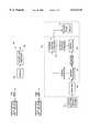
FIG. 1 is a top plan view of a work area having a plurality of work paths;
FIG. 2 is a functional block diagram of a sensor system for providing position data;
FIG. 3 is a functional block diagram used to carry out the present invention including a control system for a mobile machine;
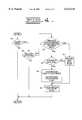
FIG. 4 is a flowchart diagram of a learning mode associated with the present invention;
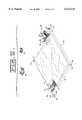
FIG. 5 is a perspective view of a work site; and
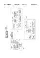
FIG. 6 is a functional block diagram of a communication system for implementing the present invention.
Referring to FIG. 1, a top plan view of awork area 20 is shown having a plurality ofwork paths 22 bounded by aperimeter 24. Acushion boundary 26 is included betweenwork paths 22 and theperimeter 24 so that small inaccuracies in data provided by sensor systems do not interfere with the present invention as described hereinbelow. Thework paths 22 are exemplary of the manner in which thework area 20 may be divided where a task such as material compacting is performed by amobile machine 28. It should be noted that a wide variety of patterns may be used to divide thework area 20 intowork paths 22. Some factors for selecting a particular pattern include the area covered during one pass of themobile machine 28, the turning radius of themobile machine 28, and the size of thework area 20. The present invention is applicable to tasks that involve traversing thework area 20 only once or several times, such as material compaction.
The present invention for establishing the perimeter of a work area for themobile machine 28 involves positioning themobile machine 28 at one location on theperimeter 24 as shown in FIG. 1. Thework area 20 may have any shape as dictated by factors such as property boundaries or area on which the task is to be performed. Thework area 20 is shown in FIG. 1 as a rectangle for illustrative purposes only and is not meant to limit the present invention to work areas having a particular shape.
The present invention includes means to generate signals representing the instantaneous position in at least two-dimensional space of a portion of themobile machine 28. Such means, as shown in FIG. 2, include various vehicleposition sensor systems 30 capable of providing information regarding the position of themobile machine 28 in two-dimensional or three-dimensional space. Several different types ofsensors 32 are suitable for use insuch sensor systems 30 including, but not limited to, inertial gyros, lasers, global positioning systems (GPS), GPS/laser combinations, and radar. In certain types ofsensor systems 30, such as theGPS satellite 34 shown in FIG. 1, position data is transmitted to areceiver 38. Thereceiver 38 is in communication with asensor processing module 46 that provides sensor data to controlsystem computer 40 as shown incontrol system 42 in FIG. 3.
Thecontrol system computer 40 includes a data processor, such as a microprocessor, random access memory, read only memory, and a data bus for receiving data from and transmitting data to various devices. Thecontrol system computer 40 executes logic and equations implemented in one or more software programs to determine actuator position command signals for operating various pumps, valves, hydraulic cylinders, motor/steering mechanisms and other servo-actuated controls for controlling movement of themobile machine 28. Servo-actuators 44 receive position commands but typically are not capable of moving to the commanded position instantaneously. Actual actuator positions are sensed and input to thesensor processing module 46 that conditions the sensor signals for use by the software programs of thecontrol system 42. The mobile machine's position data from the vehicleposition sensor system 30 may also be conditioned by thesensor processing module 46, which filters noise from the signals and performs any other processing required. Thesensor processing module 46 may be implemented in software that is executed in a computer, such as thecontrol system computer 40, or it may be implemented with electronic circuitry. Sensed parameters from thesensor processing module 46 are input to thecontrol system computer 40 for use by the software programs.
An operator may also input data, commands, or other information viacontrol panel 48. Thecontrol panel 48 consists of input means such as a keyboard, switches, buttons, and dials, and interface means such as an analog to digital or digital to analog converter operatively connected to communicate with thecontrol system computer 40. Thecontrol panel 48 also includes audio and visual display means such as a cathode ray terminal (CRT), light emitting diode readouts, lights, sounds, alarms, and the like to provide information to an operator.
To establish theperimeter 24 of thework area 20, themobile machine 28 is positioned at any location on theperimeter 24. It is most advantageous to position themobile machine 28 at acorner point 50 to reduce the number of data points that must be collected to establish theperimeter 24. When themobile machine 28 is positioned at the desired location, the operator inputs a command to thecontrol panel 48 to record the position of themobile machine 28. Thecontrol panel 48 transmits the command to thecontrol system computer 40. The position data may be available from the vehicleposition sensor system 30 continually or as requested. If the position data is available continually, the current data is recorded in thecontrol system computer 40. If the position data is only available upon request, thecontrol system computer 40 transmits the command to the vehicleposition sensor system 30 to provide the position data of themobile machine 28 at the current position of themobile machine 28. The position data is transmitted to thesensor processing module 46, conditioned, and then input to thecontrol system computer 40. The position data may be available from thesensor system 30 in two-dimensional or three-dimensional coordinates. Themobile machine 28 is then driven to another location along theperimeter 24 such as thenext corner point 50. The operator once again inputs a command to record the position of themobile machine 28. The operator moves themobile machine 28 to as many locations as desired or required along theperimeter 24 to record position data that defines thework area 20. The position data is used in a software program in thecontrol system computer 40 that planswork paths 22 for themobile machine 28 to follow while performing the task.
In order to cue thecontrol system 42 that position data to establish theperimeter 24 is about to be collected, thecontrol panel 48 may include an operator interface that allows the operator to put thecontrol system 42 in a learn mode via a switch or other input device. FIG. 4 shows a flowchart representation of learning mode logic that may be implemented in software on thecontrol system computer 40. Indecision block 54, it is determined whether the learn mode is selected. If so, then indecision block 56, it is determined whether the operator has commanded the current position data to be recorded. If so, then the logic may include a test indecision block 58 to determine whether points were entered during a previous cycle of the learning mode. If so, then the points may be displayed and the operator may be given the option of overwriting an existing point or entering a new one as shown indecision block 60. If the operator chooses to overwrite an existing data point, then the current position data overwrites the stored data point chosen by operator as shown inblock 62. Otherwise a new data point is entered as shown inblock 64. The operator may be given the option to enter the new data point at the beginning or end of the other data points, or to insert it between two of the other points. Once the data is recorded, the record data flag is cleared as shown inblock 66. Thecontrol panel 48 may include means to allow the operator to verify the establishedperimeter 24, such means including an operator display showing a graphic display of theperimeter 24 along with the coordinates of the data points. The display may also include a readout of the square footage associated with thework area 20 bounded by theperimeter 24, as well as other pertinent information as desired. Means such as a light pen or other pointing device may be provided to interact with the displayed perimeter to allow the operator to indicate a correction for a point or to enter a new point for the perimeter.
The present invention for establishing theperimeter 24 of thework area 20 may be advantageously used in a system for autonomous control of amobile machine 28. The principles and applications of the present invention lend themselves to virtually anymobile machine 28 that traverses awork area 20 while performing a task. Such mobile machinery may be equipped in known fashion with an electro-hydraulic control system 42 as discussed hereinabove. Thecontrol system 42 for autonomousmobile machinery 28 includes several software programs that may be executed in thecontrol system computer 40. These software programs include a work planner for generatingwork paths 22, a path planner for planning transitions between thework paths 22, and a path follower for determining which way to steer themobile machine 28 to follow thework paths 22. These software programs require knowledge regarding theperimeter 24 of thework area 20 for various reasons including to avoid trespassing on another's property or to avoid operating themobile machine 28 in undesirable areas such as near the edge of cliffs, lakes, or obstacles. Thecontrol system 42 may also generate thecushion boundary 26 once theperimeter 24 is established which provides a further buffer in the event thatsensor system 30 provides position data containing errors due to inaccuracies in thesensor system 30.
Referring to FIG. 5, a landfill compacting system including twomobile machines landfill site 72. In the illustrative embodiment of FIG. 5, one mobile machine is a track-type tractor 68 that spreads material to be compacted over thelandfill site 72 and the other mobile machine is awheeled landfill compactor 70 that compacts the material spread by thetractor 68. It will become apparent however, that the principles and applications of the present invention will lend themselves to virtually any mobile tool or machine with the capacity to move over or through a work site and alter the topology of the site in some fashion.
FIG. 6 shows a functional block diagram of the components included in thebase station 82, acontrol station 102 for thecompactor 70, and acontrol station 103 for thetractor 68. Thebase station 82 includes aGPS receiver 94, adata radio 96, a portable electric generator set 98, and apower supply 100. These components are packaged together and are located in proximity to the work area. The compactor'scontrol station 102 includes the phasedifferential GPS receiver 78,data radio 104,data processor 106,control panel 108, andmonitoring system 110. The tractor operator'scontrol station 103 includesGPS receiver 92, adata radio 112, acontrol panel 114, anddata processor 116.Data processors control system computer 40 shown in FIG. 3. The components in thebase station 82, and thecontrol stations compactor 70 to operate autonomously in concert withtractor 68, which, preferably, is operator-driven, as described hereinbelow.
During a start-up phase, an operator drives thecompactor 70 to acorner 50 oflandfill site 72 and uses means oncontrol panel 108, such as a switch or data entry via a keyboard, to put thecompactor 70 in autonomous mode. The operator unloads the mobileGPS base station 82, positions it at the selected location, and places it in an operational mode by starting the generator set 98. The operator then confirms operational status of thecompactor 70 in autonomous mode via a display associated withcontrol panel 108, as well as operation of theGPS base station 82.
The operator then activates the learning mode as described hereinabove and begins driving thecompactor 70 around theperimeter 24 of thework area 20. At eachcorner 50 of thework area 20, as well as at any desired intermediate points, the operator activates means viacontrol panel 108 to cue the system that the present location should be entered as a point defining theperimeter 24. The operator may place amarker 118 such as a stake or buoy at each corner to provide a visual perimeter cue to the operator of thetractor 68. Upon completion of entering thecorners 50 of theperimeter 24 in the system, the operator exits the learning mode and verifies the completion and correct entry of theperimeter 24. Thecontrol system computer 40 then calculates the compaction area and determines a work path or series ofwork paths 22 for thecompactor 70 to traverse. For example, with alandfill site 72, the travel plan will be a repetitive, systematic back and forth series ofwork paths 22 to allow thecompactor 70 to uniformly traverse thelandfill site 72 and compact the material. Thework paths 22 are traversed repeatedly as long as thecompactor 70 is activated.
The operator takes further steps to put thecompactor 70 in operational mode including lowering the blade 90, setting a parking brake, and confirming that thecompactor 70 is ready to begin autonomous operation. The operator then exits the machine and boards thetractor 68. Thetractor 68 spreads material to be compacted over thelandfill site 72 ahead of the path of thecompactor 70. The planned motion of thecompactor 70 along thework paths 22 and the position of thetractor 68 with respect to thecompactor 70 may be shown on a display associated with the tractor'scontrol panel 114. Thetractor 68 may be driven by the same operator responsible for the operation of thecompactor 70 while thecompactor 70 is operating in the autonomous mode.
The status of thecompactor 70 is transmitted via thedata radio 104 associated with the compactor'scontrol panel 102 to thetractor 68 so the operator can monitor operation and position of thecompactor 70. Further, thecontrol system 42 of thecompactor 70 may include features that receive commands, tractor status, and tractor position from thedata radio 112 associated with the tractor'scontrol panel 103. This provides the operator with means to start and stop thecompactor 70 from thetractor 68 and to perform any other functions deemed necessary to complete the task. The compactor'smonitoring system 110 monitors the position of thetractor 68 and controls the movement of thecompactor 70 with respect to the position and movement of thetractor 68. Themonitoring system 110 further keeps track of the position of thecompactor 70 and may be designed to perform some action if a specified condition is detected, such as stopping thecompactor 70 if it traverses outside theperimeter 24.
The present invention for establishing theperimeter 24 of awork site 20 thus provides means for an autonomous mobile machine to learn the desired boundaries or perimeter of operation. It is further anticipated that a mobile machine may be remotely controlled to traverse the perimeter and to enter the coordinates of the corner points 50 in thecontrol system 42 instead of requiring an operator to be onboard the mobile machine during the learning mode. The desired functions may be included entirely in one mobile machine, thereby obviating the need for a companion vehicle such as thetractor 68 andcompactor 70 combination.
Other aspects, objects and advantages of the present invention can be obtained from a study of the drawings, the disclosure and the appended claims.
Claims (13)
1. A method for establishing a perimeter of a work area for a mobile machine, the method comprising the steps of:
a) positioning the mobile machine at one location on the perimeter;
b) generating signals representing the instantaneous position in at least two-dimensional space of a portion of the mobile machine;
c) activating means for receiving the position signals in a data storage and retrieval means;
d) positioning the mobile machine at another location on the perimeter;
e) repeating steps b) through d) until the mobile machine is positioned at a final location on the perimeter; and
(f) planning a pattern of work paths of the work area by a control system computer located on the mobile machine, the pattern of work paths being a function of the perimeter, the work area, and the mobile machine.
2. The method, as set forth in claim 1, wherein the position signals are generated by a GPS sensor system.
3. The method, as set forth in claim 1, wherein the locations correspond to corners of the perimeter.
4. An apparatus for establishing a perimeter of a work area for a mobile machine, the apparatus comprising:
the mobile machine positioned at a plurality of locations on the perimeter;
means for generating signals representing the instantaneous position in at least two-dimensional space of a portion of the mobile machine at each location;
means for receiving and storing the position signals; and
a control system computer located on the mobile machine and adapted to plan a pattern of work paths of the work area as a function of the perimeter, the work area, and the mobile machine.
5. The apparatus, as set forth in claim 4, wherein the means for generating position signals is a GPS sensor system.
6. The apparatus, as set forth in claim 4, wherein the locations correspond to corners of the perimeter.
7. The apparatus, as set forth in claim 4, further comprising a data processing system including a learning mode that associates the stored position signals with the perimeter.
8. The apparatus, as set forth in claim 7, further comprising means for verifying the established perimeter.
9. The apparatus, as set forth in claim 8, wherein the means for verifying the established perimeter includes an operator display.
10. A system for establishing a perimeter of a work area for an autonomous mobile machine comprising:
a positioning system operable to provide coordinate data corresponding to the position of the mobile machine as the mobile machine traverses the work area; and
a control system located on the mobile machine having a data processor operatively connected to data storage means, program means including a learning mode, the learning mode being operable to enter position data corresponding to points on the perimeter of the work area as the mobile machine traverses the perimeter, and to store the position data in the data storage means, the control system further having a work planner for generating work paths.
11. The system, as set forth in claim 10, further comprising:
a display; and
the data processor being operable to generate output to the display to allow the operator to verify the position data entered to establish the perimeter.
12. The system, as set forth in claim 11, wherein the data processor is further operable to receive input from the operator to modify the position data entered during the learning mode.
13. A system, as set forth in claim 10, wherein the control system further includes:
a path planner for planning transitions between the work paths; and
a path follower for determining a direction to steer the mobile machine to follow the work paths.
Priority Applications (5)
| Application Number | Priority Date | Filing Date | Title |
|---|---|---|---|
| US09/130,265US6112143A (en) | 1998-08-06 | 1998-08-06 | Method and apparatus for establishing a perimeter defining an area to be traversed by a mobile machine |
| JP2000564105AJP2002522673A (en) | 1998-08-06 | 1999-07-29 | Method and apparatus for determining a boundary defining an area traversed by a mobile machine |
| DE19983437TDE19983437T1 (en) | 1998-08-06 | 1999-07-29 | Method and apparatus for setting up a perimeter defining an area to be traversed by a mobile machine |
| AU52462/99AAU754837B2 (en) | 1998-08-06 | 1999-07-29 | Method and apparatus for establishing a perimeter defining an area to be traversed by a mobile machine |
| PCT/US1999/017324WO2000008535A1 (en) | 1998-08-06 | 1999-07-29 | Method and apparatus for establishing a perimeter defining an area to be traversed by a mobile machine |
Applications Claiming Priority (1)
| Application Number | Priority Date | Filing Date | Title |
|---|---|---|---|
| US09/130,265US6112143A (en) | 1998-08-06 | 1998-08-06 | Method and apparatus for establishing a perimeter defining an area to be traversed by a mobile machine |
Publications (1)
| Publication Number | Publication Date |
|---|---|
| US6112143Atrue US6112143A (en) | 2000-08-29 |
Family
ID=22443865
Family Applications (1)
| Application Number | Title | Priority Date | Filing Date |
|---|---|---|---|
| US09/130,265Expired - Fee RelatedUS6112143A (en) | 1998-08-06 | 1998-08-06 | Method and apparatus for establishing a perimeter defining an area to be traversed by a mobile machine |
Country Status (5)
| Country | Link |
|---|---|
| US (1) | US6112143A (en) |
| JP (1) | JP2002522673A (en) |
| AU (1) | AU754837B2 (en) |
| DE (1) | DE19983437T1 (en) |
| WO (1) | WO2000008535A1 (en) |
Cited By (99)
| Publication number | Priority date | Publication date | Assignee | Title |
|---|---|---|---|---|
| US6205381B1 (en)* | 1999-03-26 | 2001-03-20 | Caterpillar Inc. | Method and apparatus for providing autoguidance for multiple agricultural machines |
| US6338013B1 (en)* | 1999-03-19 | 2002-01-08 | Bryan John Ruffner | Multifunctional mobile appliance |
| US6505124B2 (en)* | 1999-11-01 | 2003-01-07 | Gary W. Clem, Inc. | GPS system to provide planter tripping for crop research plots |
| GB2382157A (en)* | 2001-11-20 | 2003-05-21 | Bryan J Ruffner | Multifunctional mobile appliance |
| US6701239B2 (en) | 2002-04-10 | 2004-03-02 | Caterpillar Inc | Method and apparatus for controlling the updating of a machine database |
| US20040068352A1 (en)* | 2002-10-03 | 2004-04-08 | Deere & Company, A Delaware Corporation | Method and system for determining an energy-efficient path of a machine |
| US20040085037A1 (en)* | 2001-01-24 | 2004-05-06 | Jones Joseph L. | Method and system for robot localization and confinement |
| US20040193363A1 (en)* | 2003-03-27 | 2004-09-30 | Schmidt Mark Alvin | Method and system for controlling a vehicle having multiple control modes |
| US6845311B1 (en) | 2003-11-04 | 2005-01-18 | Caterpillar Inc. | Site profile based control system and method for controlling a work implement |
| US6847868B2 (en)* | 2001-08-24 | 2005-01-25 | David W. Young | Apparatus for cleaning lines on a playing surface and associated methods |
| US20050033456A1 (en)* | 2001-08-06 | 2005-02-10 | Honda Giken Kogyo Kabushiki Kaisha | Control system for plant and air-fuel ratio control system for internal combustion engine |
| US20050083196A1 (en)* | 2003-08-26 | 2005-04-21 | Ken Furem | System and method for remotely obtaining and managing machine data |
| US20050085973A1 (en)* | 2003-08-26 | 2005-04-21 | Ken Furem | System and method for remotely analyzing machine performance |
| US20050081410A1 (en)* | 2003-08-26 | 2005-04-21 | Ken Furem | System and method for distributed reporting of machine performance |
| US20050113989A1 (en)* | 2001-08-24 | 2005-05-26 | Young David W. | Apparatus for cleaning lines on a playing surface and associated methods, enhancements |
| US20050131610A1 (en)* | 2003-12-10 | 2005-06-16 | Caterpillar Inc. | Positioning system for an excavating work machine |
| US20050283294A1 (en)* | 2004-06-16 | 2005-12-22 | Lehman Allen A Jr | Method and apparatus for machine guidance at a work site |
| US20060149461A1 (en)* | 2004-12-31 | 2006-07-06 | Henry Rowley | Transportation routing |
| US7155308B2 (en) | 2000-01-24 | 2006-12-26 | Irobot Corporation | Robot obstacle detection system |
| US7178606B2 (en) | 2004-08-27 | 2007-02-20 | Caterpillar Inc | Work implement side shift control and method |
| EP1772789A1 (en)* | 2005-10-07 | 2007-04-11 | Saab Ab | Method and apparatus for generating a route |
| US20070150149A1 (en)* | 2005-12-28 | 2007-06-28 | Peterson Brandon J | Method and system for tracking the positioning and limiting the movement of mobile machinery and its appendages |
| US20070168116A1 (en)* | 2006-01-18 | 2007-07-19 | Meyer Zu Helligen Lars Peter | Method for creating reference driving tracks for agricultural working machines |
| US20070195011A1 (en)* | 2004-03-12 | 2007-08-23 | Keiji Hatori | Work area setting and managing system |
| US20070198159A1 (en)* | 2006-01-18 | 2007-08-23 | I-Guide, Llc | Robotic vehicle controller |
| US20070244610A1 (en)* | 2005-12-02 | 2007-10-18 | Ozick Daniel N | Autonomous coverage robot navigation system |
| US20070260371A1 (en)* | 2001-08-24 | 2007-11-08 | Young David W | Methods for cleaning lines on a game playing surface |
| US20070299590A1 (en)* | 2006-06-23 | 2007-12-27 | Caterpillar Inc. | System for automated excavation entry point selection |
| US20080039991A1 (en)* | 2006-08-10 | 2008-02-14 | May Reed R | Methods and systems for providing accurate vehicle positioning |
| US7332890B2 (en) | 2004-01-21 | 2008-02-19 | Irobot Corporation | Autonomous robot auto-docking and energy management systems and methods |
| US7389156B2 (en) | 2005-02-18 | 2008-06-17 | Irobot Corporation | Autonomous surface cleaning robot for wet and dry cleaning |
| US7388343B2 (en) | 2001-06-12 | 2008-06-17 | Irobot Corporation | Method and system for multi-mode coverage for an autonomous robot |
| US7430455B2 (en) | 2000-01-24 | 2008-09-30 | Irobot Corporation | Obstacle following sensor scheme for a mobile robot |
| US20080262988A1 (en)* | 2007-04-20 | 2008-10-23 | Mark Williams | Vertical curve system for surface grading |
| US20080267719A1 (en)* | 2007-04-24 | 2008-10-30 | Caterpillar Inc. | Towed compaction determination system utilizing drawbar force |
| US20090228166A1 (en)* | 2006-01-18 | 2009-09-10 | I-Guide, Llc | Robotic Vehicle Controller |
| US7620476B2 (en) | 2005-02-18 | 2009-11-17 | Irobot Corporation | Autonomous surface cleaning robot for dry cleaning |
| FR2931957A1 (en)* | 2008-06-02 | 2009-12-04 | Nav On Time | DEVICE FOR CONTROLLING MOBILE DEVICE (S) AUTOPROPULSE (S) |
| US20100076599A1 (en)* | 2008-09-20 | 2010-03-25 | Steven Jacobs | Manually driven determination of a region of interest (roi) or a path of interest (poi) for a robotic device |
| US7706917B1 (en) | 2004-07-07 | 2010-04-27 | Irobot Corporation | Celestial navigation system for an autonomous robot |
| US7761954B2 (en) | 2005-02-18 | 2010-07-27 | Irobot Corporation | Autonomous surface cleaning robot for wet and dry cleaning |
| US20100312599A1 (en)* | 2009-06-08 | 2010-12-09 | Caterpillar Inc. | System and Method for Measuring Productivity of a Machine |
| US20110224860A1 (en)* | 2001-08-24 | 2011-09-15 | David Wright Young | Apparatus for cleaning lines on a playing surface and associated methods, handle enhancements |
| US20120029755A1 (en)* | 2010-07-28 | 2012-02-02 | Johnson David A | Robotic mower area coverage system |
| US8239992B2 (en) | 2007-05-09 | 2012-08-14 | Irobot Corporation | Compact autonomous coverage robot |
| US8253368B2 (en) | 2004-01-28 | 2012-08-28 | Irobot Corporation | Debris sensor for cleaning apparatus |
| US8374721B2 (en) | 2005-12-02 | 2013-02-12 | Irobot Corporation | Robot system |
| US8382906B2 (en) | 2005-02-18 | 2013-02-26 | Irobot Corporation | Autonomous surface cleaning robot for wet cleaning |
| US8386081B2 (en) | 2002-09-13 | 2013-02-26 | Irobot Corporation | Navigational control system for a robotic device |
| US8396592B2 (en) | 2001-06-12 | 2013-03-12 | Irobot Corporation | Method and system for multi-mode coverage for an autonomous robot |
| US8417383B2 (en) | 2006-05-31 | 2013-04-09 | Irobot Corporation | Detecting robot stasis |
| US8418303B2 (en) | 2006-05-19 | 2013-04-16 | Irobot Corporation | Cleaning robot roller processing |
| US8428778B2 (en) | 2002-09-13 | 2013-04-23 | Irobot Corporation | Navigational control system for a robotic device |
| US20130103211A1 (en)* | 2011-10-25 | 2013-04-25 | Agco Corporation | Dynamic spray buffer calculation |
| US8474090B2 (en) | 2002-01-03 | 2013-07-02 | Irobot Corporation | Autonomous floor-cleaning robot |
| US8515578B2 (en) | 2002-09-13 | 2013-08-20 | Irobot Corporation | Navigational control system for a robotic device |
| US8584307B2 (en) | 2005-12-02 | 2013-11-19 | Irobot Corporation | Modular robot |
| US8600553B2 (en) | 2005-12-02 | 2013-12-03 | Irobot Corporation | Coverage robot mobility |
| US8634960B2 (en) | 2006-03-17 | 2014-01-21 | Irobot Corporation | Lawn care robot |
| US8780342B2 (en) | 2004-03-29 | 2014-07-15 | Irobot Corporation | Methods and apparatus for position estimation using reflected light sources |
| US8788092B2 (en) | 2000-01-24 | 2014-07-22 | Irobot Corporation | Obstacle following sensor scheme for a mobile robot |
| US8800107B2 (en) | 2010-02-16 | 2014-08-12 | Irobot Corporation | Vacuum brush |
| WO2014182483A1 (en)* | 2013-05-10 | 2014-11-13 | Caterpillar Inc. | System and method for re-directing a ripping path |
| US8930023B2 (en) | 2009-11-06 | 2015-01-06 | Irobot Corporation | Localization by learning of wave-signal distributions |
| US8972052B2 (en) | 2004-07-07 | 2015-03-03 | Irobot Corporation | Celestial navigation system for an autonomous vehicle |
| US8996226B1 (en)* | 2011-07-12 | 2015-03-31 | Google Inc. | Intersection completer |
| US9008835B2 (en) | 2004-06-24 | 2015-04-14 | Irobot Corporation | Remote control scheduler and method for autonomous robotic device |
| US20150167257A1 (en)* | 2012-05-22 | 2015-06-18 | Hamm Ag | Method for planning and implementation of soil compacting processes, especially for asphalt compacting |
| US9320398B2 (en) | 2005-12-02 | 2016-04-26 | Irobot Corporation | Autonomous coverage robots |
| US9420741B2 (en) | 2014-12-15 | 2016-08-23 | Irobot Corporation | Robot lawnmower mapping |
| US9510505B2 (en) | 2014-10-10 | 2016-12-06 | Irobot Corporation | Autonomous robot localization |
| US9516806B2 (en) | 2014-10-10 | 2016-12-13 | Irobot Corporation | Robotic lawn mowing boundary determination |
| US9538702B2 (en) | 2014-12-22 | 2017-01-10 | Irobot Corporation | Robotic mowing of separated lawn areas |
| US9554508B2 (en) | 2014-03-31 | 2017-01-31 | Irobot Corporation | Autonomous mobile robot |
| US9867331B1 (en) | 2014-10-28 | 2018-01-16 | Hydro-Gear Limited Partnership | Utility vehicle with onboard and remote control systems |
| US9868211B2 (en) | 2015-04-09 | 2018-01-16 | Irobot Corporation | Restricting movement of a mobile robot |
| US10021830B2 (en) | 2016-02-02 | 2018-07-17 | Irobot Corporation | Blade assembly for a grass cutting mobile robot |
| US10034421B2 (en) | 2015-07-24 | 2018-07-31 | Irobot Corporation | Controlling robotic lawnmowers |
| US10058031B1 (en) | 2015-02-28 | 2018-08-28 | Hydro-Gear Limited Partnership | Lawn tractor with electronic drive and control system |
| US10126754B2 (en)* | 2014-02-06 | 2018-11-13 | Yanmar Co., Ltd. | Method for setting travel path of work vehicle |
| CN108951374A (en)* | 2018-07-10 | 2018-12-07 | 北京踏歌艾尔机器人科技有限公司 | Roll the control method and device of engineering truck |
| US10227754B2 (en)* | 2011-04-14 | 2019-03-12 | Joy Global Surface Mining Inc | Swing automation for rope shovel |
| US20190186094A1 (en)* | 2017-12-14 | 2019-06-20 | Caterpillar Paving Products Inc. | System and method for compacting a worksite surface |
| US10459063B2 (en) | 2016-02-16 | 2019-10-29 | Irobot Corporation | Ranging and angle of arrival antenna system for a mobile robot |
| EP3403487B1 (en) | 2017-05-15 | 2019-12-04 | CLAAS KGaA mbH | Method for compacting harvested crops located in a silo |
| WO2019234020A1 (en)* | 2018-06-07 | 2019-12-12 | Husqvarna Ab | Robotic work tool system and method for defining a working area |
| US10599153B2 (en)* | 2015-12-17 | 2020-03-24 | Ammann Schweiz Ag | Method of autonomous operation of a compression apparatus |
| US10629005B1 (en) | 2014-10-20 | 2020-04-21 | Hydro-Gear Limited Partnership | Interactive sensor, communications, and control system for a utility vehicle |
| US10649457B2 (en) | 2017-05-02 | 2020-05-12 | Cnh Industrial America Llc | System and method for autonomous vehicle system planning |
| WO2021096909A1 (en) | 2019-11-15 | 2021-05-20 | Caterpillar Inc. | System for validating worksites |
| US11115798B2 (en) | 2015-07-23 | 2021-09-07 | Irobot Corporation | Pairing a beacon with a mobile robot |
| US20210372081A1 (en)* | 2020-05-28 | 2021-12-02 | Jiangsu Xcmg Construction Machinery Research Institute Ltd. | Leveling control method, device and system, and motor grader |
| US20220107644A1 (en)* | 2020-10-03 | 2022-04-07 | Viabot Inc. | Methods for setting and programming zoning for use by autonomous modular robots |
| US11470774B2 (en) | 2017-07-14 | 2022-10-18 | Irobot Corporation | Blade assembly for a grass cutting mobile robot |
| EP4194988A1 (en) | 2021-12-12 | 2023-06-14 | Caterpillar Inc. | System and method for generating work plan for autonomous operation of a compactor |
| DE102023107838A1 (en) | 2022-04-08 | 2023-10-12 | Caterpillar Paving Products Inc. | CONTROL SYSTEM AND METHOD FOR ACTIVE TRAVEL MONITORING OF A COMPRESSOR |
| US11988525B2 (en) | 2022-02-23 | 2024-05-21 | Ford Global Technologies, Llc | Autonomous vehicle with automated following of person outside vehicle |
| US12065788B2 (en) | 2021-06-23 | 2024-08-20 | Caterpillar Paving Products Inc. | System and method for marking a boundary while defining an autonomous worksite |
| US12077942B2 (en) | 2019-04-24 | 2024-09-03 | Komatsu Ltd. | System and a method for controlling a work machine |
Families Citing this family (10)
| Publication number | Priority date | Publication date | Assignee | Title |
|---|---|---|---|---|
| DE102006015204A1 (en)* | 2006-03-30 | 2007-10-18 | Claas Selbstfahrende Erntemaschinen Gmbh | Method for creating a route plan for agricultural machine systems |
| CN103669362B (en)* | 2013-12-27 | 2016-01-27 | 中国电建集团成都勘测设计研究院有限公司 | To close a position machine Real-Time Monitoring navigation system and method |
| CN105446350B (en)* | 2014-09-26 | 2018-05-29 | 科沃斯机器人股份有限公司 | Self-movement robot moves boundary demarcation method |
| JP6716195B2 (en)* | 2015-01-19 | 2020-07-01 | 鹿島建設株式会社 | Construction machine construction method and construction machine construction system |
| ES2887086T3 (en) | 2015-07-10 | 2021-12-21 | Lantmaennen Functional Foods Ab | Procedure to produce egg yolk with high af-16 content |
| CN108646755A (en)* | 2018-07-03 | 2018-10-12 | 清华大学 | A kind of cubic meter of intelligent rcc system |
| JP7142597B2 (en)* | 2019-04-01 | 2022-09-27 | ヤンマーパワーテクノロジー株式会社 | Running area shape registration system |
| US11591757B2 (en)* | 2019-04-17 | 2023-02-28 | Caterpillar Paving Products Inc. | System and method for machine control |
| JP7281955B2 (en)* | 2019-04-24 | 2023-05-26 | 鹿島建設株式会社 | Safety support device and safety monitoring method |
| JP6872654B2 (en)* | 2020-04-02 | 2021-05-19 | 鹿島建設株式会社 | Construction machine construction method |
Citations (11)
| Publication number | Priority date | Publication date | Assignee | Title |
|---|---|---|---|---|
| US4600999A (en)* | 1982-07-13 | 1986-07-15 | Kubota, Ltd. | Automatic running work vehicle |
| US4674048A (en)* | 1983-10-26 | 1987-06-16 | Automax Kabushiki-Kaisha | Multiple robot control system using grid coordinate system for tracking and completing travel over a mapped region containing obstructions |
| EP0490736A2 (en)* | 1990-12-07 | 1992-06-17 | Lg Electronics Inc. | Method for automatically controlling a travelling and cleaning operation of vacuum cleaners |
| US5204814A (en)* | 1990-11-13 | 1993-04-20 | Mobot, Inc. | Autonomous lawn mower |
| US5471391A (en)* | 1993-12-08 | 1995-11-28 | Caterpillar Inc. | Method and apparatus for operating compacting machinery relative to a work site |
| US5631658A (en)* | 1993-12-08 | 1997-05-20 | Caterpillar Inc. | Method and apparatus for operating geography-altering machinery relative to a work site |
| US5646844A (en)* | 1994-04-18 | 1997-07-08 | Caterpillar Inc. | Method and apparatus for real-time monitoring and coordination of multiple geography altering machines on a work site |
| US5684476A (en)* | 1993-12-30 | 1997-11-04 | Concord, Inc. | Field navigation system |
| EP0821296A2 (en)* | 1996-07-23 | 1998-01-28 | CLAAS KGaA | Route planning system for agricultural working vehicles |
| WO1998019514A1 (en)* | 1996-11-06 | 1998-05-14 | Maasland N.V. | A soil working implement |
| US5974347A (en)* | 1997-03-14 | 1999-10-26 | Nelson; Russell G. | Automated lawn mower |
- 1998
- 1998-08-06USUS09/130,265patent/US6112143A/ennot_activeExpired - Fee Related
- 1999
- 1999-07-29DEDE19983437Tpatent/DE19983437T1/ennot_activeWithdrawn
- 1999-07-29JPJP2000564105Apatent/JP2002522673A/enactivePending
- 1999-07-29AUAU52462/99Apatent/AU754837B2/ennot_activeCeased
- 1999-07-29WOPCT/US1999/017324patent/WO2000008535A1/enactiveIP Right Grant
Patent Citations (12)
| Publication number | Priority date | Publication date | Assignee | Title |
|---|---|---|---|---|
| US4600999A (en)* | 1982-07-13 | 1986-07-15 | Kubota, Ltd. | Automatic running work vehicle |
| US4674048A (en)* | 1983-10-26 | 1987-06-16 | Automax Kabushiki-Kaisha | Multiple robot control system using grid coordinate system for tracking and completing travel over a mapped region containing obstructions |
| US5204814A (en)* | 1990-11-13 | 1993-04-20 | Mobot, Inc. | Autonomous lawn mower |
| EP0490736A2 (en)* | 1990-12-07 | 1992-06-17 | Lg Electronics Inc. | Method for automatically controlling a travelling and cleaning operation of vacuum cleaners |
| US5471391A (en)* | 1993-12-08 | 1995-11-28 | Caterpillar Inc. | Method and apparatus for operating compacting machinery relative to a work site |
| US5493494A (en)* | 1993-12-08 | 1996-02-20 | Caterpillar, Inc. | Method and apparatus for operating compacting machinery relative to a work site |
| US5631658A (en)* | 1993-12-08 | 1997-05-20 | Caterpillar Inc. | Method and apparatus for operating geography-altering machinery relative to a work site |
| US5684476A (en)* | 1993-12-30 | 1997-11-04 | Concord, Inc. | Field navigation system |
| US5646844A (en)* | 1994-04-18 | 1997-07-08 | Caterpillar Inc. | Method and apparatus for real-time monitoring and coordination of multiple geography altering machines on a work site |
| EP0821296A2 (en)* | 1996-07-23 | 1998-01-28 | CLAAS KGaA | Route planning system for agricultural working vehicles |
| WO1998019514A1 (en)* | 1996-11-06 | 1998-05-14 | Maasland N.V. | A soil working implement |
| US5974347A (en)* | 1997-03-14 | 1999-10-26 | Nelson; Russell G. | Automated lawn mower |
Cited By (270)
| Publication number | Priority date | Publication date | Assignee | Title |
|---|---|---|---|---|
| US6338013B1 (en)* | 1999-03-19 | 2002-01-08 | Bryan John Ruffner | Multifunctional mobile appliance |
| US6502017B2 (en)* | 1999-03-19 | 2002-12-31 | Bryan John Ruffner | Multifunctional mobile appliance |
| US6650975B2 (en)* | 1999-03-19 | 2003-11-18 | Bryan John Ruffner | Multifunctional mobile appliance |
| US6205381B1 (en)* | 1999-03-26 | 2001-03-20 | Caterpillar Inc. | Method and apparatus for providing autoguidance for multiple agricultural machines |
| US6611738B2 (en) | 1999-07-12 | 2003-08-26 | Bryan J. Ruffner | Multifunctional mobile appliance |
| US6505124B2 (en)* | 1999-11-01 | 2003-01-07 | Gary W. Clem, Inc. | GPS system to provide planter tripping for crop research plots |
| US8412377B2 (en) | 2000-01-24 | 2013-04-02 | Irobot Corporation | Obstacle following sensor scheme for a mobile robot |
| US9446521B2 (en) | 2000-01-24 | 2016-09-20 | Irobot Corporation | Obstacle following sensor scheme for a mobile robot |
| US8478442B2 (en) | 2000-01-24 | 2013-07-02 | Irobot Corporation | Obstacle following sensor scheme for a mobile robot |
| US8565920B2 (en) | 2000-01-24 | 2013-10-22 | Irobot Corporation | Obstacle following sensor scheme for a mobile robot |
| US7155308B2 (en) | 2000-01-24 | 2006-12-26 | Irobot Corporation | Robot obstacle detection system |
| US7430455B2 (en) | 2000-01-24 | 2008-09-30 | Irobot Corporation | Obstacle following sensor scheme for a mobile robot |
| US8788092B2 (en) | 2000-01-24 | 2014-07-22 | Irobot Corporation | Obstacle following sensor scheme for a mobile robot |
| US8761935B2 (en) | 2000-01-24 | 2014-06-24 | Irobot Corporation | Obstacle following sensor scheme for a mobile robot |
| US9144361B2 (en) | 2000-04-04 | 2015-09-29 | Irobot Corporation | Debris sensor for cleaning apparatus |
| US8659255B2 (en) | 2001-01-24 | 2014-02-25 | Irobot Corporation | Robot confinement |
| US8659256B2 (en) | 2001-01-24 | 2014-02-25 | Irobot Corporation | Robot confinement |
| US7579803B2 (en) | 2001-01-24 | 2009-08-25 | Irobot Corporation | Robot confinement |
| US7567052B2 (en) | 2001-01-24 | 2009-07-28 | Irobot Corporation | Robot navigation |
| US9038233B2 (en) | 2001-01-24 | 2015-05-26 | Irobot Corporation | Autonomous floor-cleaning robot |
| US6781338B2 (en)* | 2001-01-24 | 2004-08-24 | Irobot Corporation | Method and system for robot localization and confinement |
| US9622635B2 (en) | 2001-01-24 | 2017-04-18 | Irobot Corporation | Autonomous floor-cleaning robot |
| US10824165B2 (en) | 2001-01-24 | 2020-11-03 | Irobot Corporation | Robot confinement |
| US9958871B2 (en) | 2001-01-24 | 2018-05-01 | Irobot Corporation | Robot confinement |
| US9167946B2 (en) | 2001-01-24 | 2015-10-27 | Irobot Corporation | Autonomous floor cleaning robot |
| US20040085037A1 (en)* | 2001-01-24 | 2004-05-06 | Jones Joseph L. | Method and system for robot localization and confinement |
| US8368339B2 (en) | 2001-01-24 | 2013-02-05 | Irobot Corporation | Robot confinement |
| US9582005B2 (en) | 2001-01-24 | 2017-02-28 | Irobot Corporation | Robot confinement |
| US7388343B2 (en) | 2001-06-12 | 2008-06-17 | Irobot Corporation | Method and system for multi-mode coverage for an autonomous robot |
| US20100263142A1 (en)* | 2001-06-12 | 2010-10-21 | Irobot Corporation | Method and system for multi-mode coverage for an autonomous robot |
| US7663333B2 (en) | 2001-06-12 | 2010-02-16 | Irobot Corporation | Method and system for multi-mode coverage for an autonomous robot |
| US8838274B2 (en) | 2001-06-12 | 2014-09-16 | Irobot Corporation | Method and system for multi-mode coverage for an autonomous robot |
| US7429843B2 (en) | 2001-06-12 | 2008-09-30 | Irobot Corporation | Method and system for multi-mode coverage for an autonomous robot |
| US8463438B2 (en) | 2001-06-12 | 2013-06-11 | Irobot Corporation | Method and system for multi-mode coverage for an autonomous robot |
| US8396592B2 (en) | 2001-06-12 | 2013-03-12 | Irobot Corporation | Method and system for multi-mode coverage for an autonomous robot |
| US9104204B2 (en) | 2001-06-12 | 2015-08-11 | Irobot Corporation | Method and system for multi-mode coverage for an autonomous robot |
| US20050033456A1 (en)* | 2001-08-06 | 2005-02-10 | Honda Giken Kogyo Kabushiki Kaisha | Control system for plant and air-fuel ratio control system for internal combustion engine |
| US20050113989A1 (en)* | 2001-08-24 | 2005-05-26 | Young David W. | Apparatus for cleaning lines on a playing surface and associated methods, enhancements |
| US20070260371A1 (en)* | 2001-08-24 | 2007-11-08 | Young David W | Methods for cleaning lines on a game playing surface |
| US9128487B2 (en) | 2001-08-24 | 2015-09-08 | David Wright Young | Apparatus for cleaning lines on a playing surface and associated methods, handle enhancements |
| US6847868B2 (en)* | 2001-08-24 | 2005-01-25 | David W. Young | Apparatus for cleaning lines on a playing surface and associated methods |
| US9651949B2 (en) | 2001-08-24 | 2017-05-16 | David Wright Young | Apparatus for cleaning lines on a playing surface and associated methods, other handle enhancements |
| US7957859B2 (en) | 2001-08-24 | 2011-06-07 | David Wright Young | Methods for cleaning lines on a game playing surface |
| US20110224860A1 (en)* | 2001-08-24 | 2011-09-15 | David Wright Young | Apparatus for cleaning lines on a playing surface and associated methods, handle enhancements |
| US7245994B2 (en) | 2001-08-24 | 2007-07-17 | David Wright Young | Apparatus for cleaning lines on a playing surface and associated methods, enhancements |
| GB2382157A (en)* | 2001-11-20 | 2003-05-21 | Bryan J Ruffner | Multifunctional mobile appliance |
| US8656550B2 (en) | 2002-01-03 | 2014-02-25 | Irobot Corporation | Autonomous floor-cleaning robot |
| US8474090B2 (en) | 2002-01-03 | 2013-07-02 | Irobot Corporation | Autonomous floor-cleaning robot |
| US8671507B2 (en) | 2002-01-03 | 2014-03-18 | Irobot Corporation | Autonomous floor-cleaning robot |
| US8516651B2 (en) | 2002-01-03 | 2013-08-27 | Irobot Corporation | Autonomous floor-cleaning robot |
| US8763199B2 (en) | 2002-01-03 | 2014-07-01 | Irobot Corporation | Autonomous floor-cleaning robot |
| US9128486B2 (en) | 2002-01-24 | 2015-09-08 | Irobot Corporation | Navigational control system for a robotic device |
| US6701239B2 (en) | 2002-04-10 | 2004-03-02 | Caterpillar Inc | Method and apparatus for controlling the updating of a machine database |
| US8515578B2 (en) | 2002-09-13 | 2013-08-20 | Irobot Corporation | Navigational control system for a robotic device |
| US8781626B2 (en) | 2002-09-13 | 2014-07-15 | Irobot Corporation | Navigational control system for a robotic device |
| US9949608B2 (en) | 2002-09-13 | 2018-04-24 | Irobot Corporation | Navigational control system for a robotic device |
| US8793020B2 (en) | 2002-09-13 | 2014-07-29 | Irobot Corporation | Navigational control system for a robotic device |
| US8386081B2 (en) | 2002-09-13 | 2013-02-26 | Irobot Corporation | Navigational control system for a robotic device |
| US8428778B2 (en) | 2002-09-13 | 2013-04-23 | Irobot Corporation | Navigational control system for a robotic device |
| US20040068352A1 (en)* | 2002-10-03 | 2004-04-08 | Deere & Company, A Delaware Corporation | Method and system for determining an energy-efficient path of a machine |
| US6728607B1 (en)* | 2002-10-03 | 2004-04-27 | Deere & Company | Method and system for determining an energy-efficient path of a machine |
| US20040193363A1 (en)* | 2003-03-27 | 2004-09-30 | Schmidt Mark Alvin | Method and system for controlling a vehicle having multiple control modes |
| US6813557B2 (en)* | 2003-03-27 | 2004-11-02 | Deere & Company | Method and system for controlling a vehicle having multiple control modes |
| US8306797B2 (en) | 2003-08-26 | 2012-11-06 | Siemens Industry, Inc. | System and method for remotely analyzing machine performance |
| US8275576B2 (en) | 2003-08-26 | 2012-09-25 | Siemens Industry, Inc. | System and method for distributed reporting of machine performance |
| US20080201108A1 (en)* | 2003-08-26 | 2008-08-21 | Siemens Corporation | System and Method for Distributed Reporting of Machine Performance |
| US20050085973A1 (en)* | 2003-08-26 | 2005-04-21 | Ken Furem | System and method for remotely analyzing machine performance |
| US7406399B2 (en)* | 2003-08-26 | 2008-07-29 | Siemens Energy & Automation, Inc. | System and method for distributed reporting of machine performance |
| US20050081410A1 (en)* | 2003-08-26 | 2005-04-21 | Ken Furem | System and method for distributed reporting of machine performance |
| US20110231169A1 (en)* | 2003-08-26 | 2011-09-22 | Siemens Industry, Inc. | System and Method for Remotely Analyzing Machine Performance |
| US7689394B2 (en) | 2003-08-26 | 2010-03-30 | Siemens Industry, Inc. | System and method for remotely analyzing machine performance |
| US7181370B2 (en)* | 2003-08-26 | 2007-02-20 | Siemens Energy & Automation, Inc. | System and method for remotely obtaining and managing machine data |
| US20050083196A1 (en)* | 2003-08-26 | 2005-04-21 | Ken Furem | System and method for remotely obtaining and managing machine data |
| US6845311B1 (en) | 2003-11-04 | 2005-01-18 | Caterpillar Inc. | Site profile based control system and method for controlling a work implement |
| US20050131610A1 (en)* | 2003-12-10 | 2005-06-16 | Caterpillar Inc. | Positioning system for an excavating work machine |
| US7079931B2 (en) | 2003-12-10 | 2006-07-18 | Caterpillar Inc. | Positioning system for an excavating work machine |
| US7332890B2 (en) | 2004-01-21 | 2008-02-19 | Irobot Corporation | Autonomous robot auto-docking and energy management systems and methods |
| US9215957B2 (en) | 2004-01-21 | 2015-12-22 | Irobot Corporation | Autonomous robot auto-docking and energy management systems and methods |
| US8749196B2 (en) | 2004-01-21 | 2014-06-10 | Irobot Corporation | Autonomous robot auto-docking and energy management systems and methods |
| US8461803B2 (en) | 2004-01-21 | 2013-06-11 | Irobot Corporation | Autonomous robot auto-docking and energy management systems and methods |
| US8854001B2 (en) | 2004-01-21 | 2014-10-07 | Irobot Corporation | Autonomous robot auto-docking and energy management systems and methods |
| US8390251B2 (en) | 2004-01-21 | 2013-03-05 | Irobot Corporation | Autonomous robot auto-docking and energy management systems and methods |
| US8253368B2 (en) | 2004-01-28 | 2012-08-28 | Irobot Corporation | Debris sensor for cleaning apparatus |
| US8456125B2 (en) | 2004-01-28 | 2013-06-04 | Irobot Corporation | Debris sensor for cleaning apparatus |
| US8378613B2 (en) | 2004-01-28 | 2013-02-19 | Irobot Corporation | Debris sensor for cleaning apparatus |
| US8598829B2 (en) | 2004-01-28 | 2013-12-03 | Irobot Corporation | Debris sensor for cleaning apparatus |
| US20070195011A1 (en)* | 2004-03-12 | 2007-08-23 | Keiji Hatori | Work area setting and managing system |
| US8780342B2 (en) | 2004-03-29 | 2014-07-15 | Irobot Corporation | Methods and apparatus for position estimation using reflected light sources |
| US9360300B2 (en) | 2004-03-29 | 2016-06-07 | Irobot Corporation | Methods and apparatus for position estimation using reflected light sources |
| US20050283294A1 (en)* | 2004-06-16 | 2005-12-22 | Lehman Allen A Jr | Method and apparatus for machine guidance at a work site |
| US9008835B2 (en) | 2004-06-24 | 2015-04-14 | Irobot Corporation | Remote control scheduler and method for autonomous robotic device |
| US9486924B2 (en) | 2004-06-24 | 2016-11-08 | Irobot Corporation | Remote control scheduler and method for autonomous robotic device |
| US8972052B2 (en) | 2004-07-07 | 2015-03-03 | Irobot Corporation | Celestial navigation system for an autonomous vehicle |
| US7706917B1 (en) | 2004-07-07 | 2010-04-27 | Irobot Corporation | Celestial navigation system for an autonomous robot |
| US8594840B1 (en) | 2004-07-07 | 2013-11-26 | Irobot Corporation | Celestial navigation system for an autonomous robot |
| US9223749B2 (en) | 2004-07-07 | 2015-12-29 | Irobot Corporation | Celestial navigation system for an autonomous vehicle |
| US9229454B1 (en) | 2004-07-07 | 2016-01-05 | Irobot Corporation | Autonomous mobile robot system |
| US8634958B1 (en) | 2004-07-07 | 2014-01-21 | Irobot Corporation | Celestial navigation system for an autonomous robot |
| US8874264B1 (en) | 2004-07-07 | 2014-10-28 | Irobot Corporation | Celestial navigation system for an autonomous robot |
| US8634956B1 (en) | 2004-07-07 | 2014-01-21 | Irobot Corporation | Celestial navigation system for an autonomous robot |
| US20070125557A1 (en)* | 2004-08-27 | 2007-06-07 | Caterpillar Inc. | Work implement side shift control and method |
| US7178606B2 (en) | 2004-08-27 | 2007-02-20 | Caterpillar Inc | Work implement side shift control and method |
| US7908080B2 (en)* | 2004-12-31 | 2011-03-15 | Google Inc. | Transportation routing |
| US9709415B2 (en) | 2004-12-31 | 2017-07-18 | Google Inc. | Transportation routing |
| US11092455B2 (en) | 2004-12-31 | 2021-08-17 | Google Llc | Transportation routing |
| US9945686B2 (en) | 2004-12-31 | 2018-04-17 | Google Llc | Transportation routing |
| US9778055B2 (en) | 2004-12-31 | 2017-10-03 | Google Inc. | Transportation routing |
| US20060149461A1 (en)* | 2004-12-31 | 2006-07-06 | Henry Rowley | Transportation routing |
| US8606514B2 (en) | 2004-12-31 | 2013-12-10 | Google Inc. | Transportation routing |
| US8798917B2 (en) | 2004-12-31 | 2014-08-05 | Google Inc. | Transportation routing |
| US8387193B2 (en) | 2005-02-18 | 2013-03-05 | Irobot Corporation | Autonomous surface cleaning robot for wet and dry cleaning |
| US7761954B2 (en) | 2005-02-18 | 2010-07-27 | Irobot Corporation | Autonomous surface cleaning robot for wet and dry cleaning |
| US8392021B2 (en) | 2005-02-18 | 2013-03-05 | Irobot Corporation | Autonomous surface cleaning robot for wet cleaning |
| US8966707B2 (en) | 2005-02-18 | 2015-03-03 | Irobot Corporation | Autonomous surface cleaning robot for dry cleaning |
| US8382906B2 (en) | 2005-02-18 | 2013-02-26 | Irobot Corporation | Autonomous surface cleaning robot for wet cleaning |
| US8855813B2 (en) | 2005-02-18 | 2014-10-07 | Irobot Corporation | Autonomous surface cleaning robot for wet and dry cleaning |
| US8985127B2 (en) | 2005-02-18 | 2015-03-24 | Irobot Corporation | Autonomous surface cleaning robot for wet cleaning |
| US9445702B2 (en) | 2005-02-18 | 2016-09-20 | Irobot Corporation | Autonomous surface cleaning robot for wet and dry cleaning |
| US7620476B2 (en) | 2005-02-18 | 2009-11-17 | Irobot Corporation | Autonomous surface cleaning robot for dry cleaning |
| US8774966B2 (en) | 2005-02-18 | 2014-07-08 | Irobot Corporation | Autonomous surface cleaning robot for wet and dry cleaning |
| US10470629B2 (en) | 2005-02-18 | 2019-11-12 | Irobot Corporation | Autonomous surface cleaning robot for dry cleaning |
| US7389156B2 (en) | 2005-02-18 | 2008-06-17 | Irobot Corporation | Autonomous surface cleaning robot for wet and dry cleaning |
| US8670866B2 (en) | 2005-02-18 | 2014-03-11 | Irobot Corporation | Autonomous surface cleaning robot for wet and dry cleaning |
| US8739355B2 (en) | 2005-02-18 | 2014-06-03 | Irobot Corporation | Autonomous surface cleaning robot for dry cleaning |
| US8782848B2 (en) | 2005-02-18 | 2014-07-22 | Irobot Corporation | Autonomous surface cleaning robot for dry cleaning |
| US20070112478A1 (en)* | 2005-10-07 | 2007-05-17 | Saab Ab | Method and system for generating a route |
| EP1772789A1 (en)* | 2005-10-07 | 2007-04-11 | Saab Ab | Method and apparatus for generating a route |
| US9097527B2 (en) | 2005-10-07 | 2015-08-04 | Saab Ab | Method and system for generating a route |
| US8380350B2 (en) | 2005-12-02 | 2013-02-19 | Irobot Corporation | Autonomous coverage robot navigation system |
| US9392920B2 (en) | 2005-12-02 | 2016-07-19 | Irobot Corporation | Robot system |
| US8374721B2 (en) | 2005-12-02 | 2013-02-12 | Irobot Corporation | Robot system |
| US9149170B2 (en) | 2005-12-02 | 2015-10-06 | Irobot Corporation | Navigating autonomous coverage robots |
| US9144360B2 (en) | 2005-12-02 | 2015-09-29 | Irobot Corporation | Autonomous coverage robot navigation system |
| US8761931B2 (en) | 2005-12-02 | 2014-06-24 | Irobot Corporation | Robot system |
| US8954192B2 (en) | 2005-12-02 | 2015-02-10 | Irobot Corporation | Navigating autonomous coverage robots |
| US20070244610A1 (en)* | 2005-12-02 | 2007-10-18 | Ozick Daniel N | Autonomous coverage robot navigation system |
| US9320398B2 (en) | 2005-12-02 | 2016-04-26 | Irobot Corporation | Autonomous coverage robots |
| US8661605B2 (en) | 2005-12-02 | 2014-03-04 | Irobot Corporation | Coverage robot mobility |
| US8950038B2 (en) | 2005-12-02 | 2015-02-10 | Irobot Corporation | Modular robot |
| US8600553B2 (en) | 2005-12-02 | 2013-12-03 | Irobot Corporation | Coverage robot mobility |
| US8606401B2 (en) | 2005-12-02 | 2013-12-10 | Irobot Corporation | Autonomous coverage robot navigation system |
| US10524629B2 (en) | 2005-12-02 | 2020-01-07 | Irobot Corporation | Modular Robot |
| US9599990B2 (en) | 2005-12-02 | 2017-03-21 | Irobot Corporation | Robot system |
| US8584305B2 (en) | 2005-12-02 | 2013-11-19 | Irobot Corporation | Modular robot |
| US8978196B2 (en) | 2005-12-02 | 2015-03-17 | Irobot Corporation | Coverage robot mobility |
| US8584307B2 (en) | 2005-12-02 | 2013-11-19 | Irobot Corporation | Modular robot |
| US20070150149A1 (en)* | 2005-12-28 | 2007-06-28 | Peterson Brandon J | Method and system for tracking the positioning and limiting the movement of mobile machinery and its appendages |
| WO2007079084A3 (en)* | 2005-12-28 | 2008-11-20 | Wildcat Technologies Llc | Method and system for tracking the positioning and limiting the movement of mobile machinery and its appendages |
| US7734397B2 (en) | 2005-12-28 | 2010-06-08 | Wildcat Technologies, Llc | Method and system for tracking the positioning and limiting the movement of mobile machinery and its appendages |
| US20090228166A1 (en)* | 2006-01-18 | 2009-09-10 | I-Guide, Llc | Robotic Vehicle Controller |
| US7953526B2 (en) | 2006-01-18 | 2011-05-31 | I-Guide Robotics, Inc. | Robotic vehicle controller |
| US20070198159A1 (en)* | 2006-01-18 | 2007-08-23 | I-Guide, Llc | Robotic vehicle controller |
| US20070168116A1 (en)* | 2006-01-18 | 2007-07-19 | Meyer Zu Helligen Lars Peter | Method for creating reference driving tracks for agricultural working machines |
| US8239083B2 (en) | 2006-01-18 | 2012-08-07 | I-Guide Robotics, Inc. | Robotic vehicle controller |
| US8645016B2 (en) | 2006-01-18 | 2014-02-04 | I-Guide Robotics, Inc. | Robotic vehicle controller |
| US7729834B2 (en)* | 2006-01-18 | 2010-06-01 | Claas Selbstfahrende Erntemaschinen Gmbh | Method for creating reference driving tracks for agricultural working machines |
| US8868237B2 (en) | 2006-03-17 | 2014-10-21 | Irobot Corporation | Robot confinement |
| US8954193B2 (en) | 2006-03-17 | 2015-02-10 | Irobot Corporation | Lawn care robot |
| US9713302B2 (en) | 2006-03-17 | 2017-07-25 | Irobot Corporation | Robot confinement |
| US9043952B2 (en) | 2006-03-17 | 2015-06-02 | Irobot Corporation | Lawn care robot |
| US9043953B2 (en) | 2006-03-17 | 2015-06-02 | Irobot Corporation | Lawn care robot |
| US10037038B2 (en) | 2006-03-17 | 2018-07-31 | Irobot Corporation | Lawn care robot |
| US11194342B2 (en) | 2006-03-17 | 2021-12-07 | Irobot Corporation | Lawn care robot |
| US8781627B2 (en) | 2006-03-17 | 2014-07-15 | Irobot Corporation | Robot confinement |
| US8634960B2 (en) | 2006-03-17 | 2014-01-21 | Irobot Corporation | Lawn care robot |
| US8418303B2 (en) | 2006-05-19 | 2013-04-16 | Irobot Corporation | Cleaning robot roller processing |
| US9492048B2 (en) | 2006-05-19 | 2016-11-15 | Irobot Corporation | Removing debris from cleaning robots |
| US9955841B2 (en) | 2006-05-19 | 2018-05-01 | Irobot Corporation | Removing debris from cleaning robots |
| US8572799B2 (en) | 2006-05-19 | 2013-11-05 | Irobot Corporation | Removing debris from cleaning robots |
| US10244915B2 (en) | 2006-05-19 | 2019-04-02 | Irobot Corporation | Coverage robots and associated cleaning bins |
| US8528157B2 (en) | 2006-05-19 | 2013-09-10 | Irobot Corporation | Coverage robots and associated cleaning bins |
| US8417383B2 (en) | 2006-05-31 | 2013-04-09 | Irobot Corporation | Detecting robot stasis |
| US9317038B2 (en) | 2006-05-31 | 2016-04-19 | Irobot Corporation | Detecting robot stasis |
| US20070299590A1 (en)* | 2006-06-23 | 2007-12-27 | Caterpillar Inc. | System for automated excavation entry point selection |
| US7509198B2 (en)* | 2006-06-23 | 2009-03-24 | Caterpillar Inc. | System for automated excavation entry point selection |
| US20080039991A1 (en)* | 2006-08-10 | 2008-02-14 | May Reed R | Methods and systems for providing accurate vehicle positioning |
| US8073791B2 (en) | 2007-04-20 | 2011-12-06 | Mark Williams | Vertical curve system for surface grading |
| US8788440B2 (en) | 2007-04-20 | 2014-07-22 | Mark Williams | Vertical curve system for surface grading |
| US20080262988A1 (en)* | 2007-04-20 | 2008-10-23 | Mark Williams | Vertical curve system for surface grading |
| US20080267719A1 (en)* | 2007-04-24 | 2008-10-30 | Caterpillar Inc. | Towed compaction determination system utilizing drawbar force |
| US11072250B2 (en) | 2007-05-09 | 2021-07-27 | Irobot Corporation | Autonomous coverage robot sensing |
| US8726454B2 (en) | 2007-05-09 | 2014-05-20 | Irobot Corporation | Autonomous coverage robot |
| US8438695B2 (en) | 2007-05-09 | 2013-05-14 | Irobot Corporation | Autonomous coverage robot sensing |
| US10299652B2 (en) | 2007-05-09 | 2019-05-28 | Irobot Corporation | Autonomous coverage robot |
| US8839477B2 (en) | 2007-05-09 | 2014-09-23 | Irobot Corporation | Compact autonomous coverage robot |
| US10070764B2 (en) | 2007-05-09 | 2018-09-11 | Irobot Corporation | Compact autonomous coverage robot |
| US11498438B2 (en) | 2007-05-09 | 2022-11-15 | Irobot Corporation | Autonomous coverage robot |
| US8239992B2 (en) | 2007-05-09 | 2012-08-14 | Irobot Corporation | Compact autonomous coverage robot |
| US9480381B2 (en) | 2007-05-09 | 2016-11-01 | Irobot Corporation | Compact autonomous coverage robot |
| FR2931957A1 (en)* | 2008-06-02 | 2009-12-04 | Nav On Time | DEVICE FOR CONTROLLING MOBILE DEVICE (S) AUTOPROPULSE (S) |
| WO2009156631A1 (en)* | 2008-06-02 | 2009-12-30 | Nav On Time | Method for controlling self-propelled mobile apparatus(es) |
| US8527197B2 (en) | 2008-06-02 | 2013-09-03 | Nav On Time | Control device for one or more self-propelled mobile apparatus |
| US20110142099A1 (en)* | 2008-06-02 | 2011-06-16 | Nav On Time | Control device for one or more self-propelled mobile apparatus |
| US20100076599A1 (en)* | 2008-09-20 | 2010-03-25 | Steven Jacobs | Manually driven determination of a region of interest (roi) or a path of interest (poi) for a robotic device |
| US20100312599A1 (en)* | 2009-06-08 | 2010-12-09 | Caterpillar Inc. | System and Method for Measuring Productivity of a Machine |
| US8930023B2 (en) | 2009-11-06 | 2015-01-06 | Irobot Corporation | Localization by learning of wave-signal distributions |
| US10314449B2 (en) | 2010-02-16 | 2019-06-11 | Irobot Corporation | Vacuum brush |
| US8800107B2 (en) | 2010-02-16 | 2014-08-12 | Irobot Corporation | Vacuum brush |
| US11058271B2 (en) | 2010-02-16 | 2021-07-13 | Irobot Corporation | Vacuum brush |
| US9807925B2 (en)* | 2010-07-28 | 2017-11-07 | Deere & Company | Robotic mower area coverage system |
| US20120029755A1 (en)* | 2010-07-28 | 2012-02-02 | Johnson David A | Robotic mower area coverage system |
| US12018463B2 (en) | 2011-04-14 | 2024-06-25 | Joy Global Surface Mining Inc | Swing automation for rope shovel |
| US11028560B2 (en) | 2011-04-14 | 2021-06-08 | Joy Global Surface Mining Inc | Swing automation for rope shovel |
| US10227754B2 (en)* | 2011-04-14 | 2019-03-12 | Joy Global Surface Mining Inc | Swing automation for rope shovel |
| US9261379B1 (en)* | 2011-07-12 | 2016-02-16 | Google Inc. | Intersection completer |
| US8996226B1 (en)* | 2011-07-12 | 2015-03-31 | Google Inc. | Intersection completer |
| US8571764B2 (en)* | 2011-10-25 | 2013-10-29 | Agco Corporation | Dynamic spray buffer calculation |
| US20130103211A1 (en)* | 2011-10-25 | 2013-04-25 | Agco Corporation | Dynamic spray buffer calculation |
| US9982397B2 (en)* | 2012-05-22 | 2018-05-29 | Hamm Ag | Method for planning and implementation of soil compacting processes, especially for asphalt compacting |
| US20150167257A1 (en)* | 2012-05-22 | 2015-06-18 | Hamm Ag | Method for planning and implementation of soil compacting processes, especially for asphalt compacting |
| WO2014182483A1 (en)* | 2013-05-10 | 2014-11-13 | Caterpillar Inc. | System and method for re-directing a ripping path |
| US9002593B2 (en) | 2013-05-10 | 2015-04-07 | Caterpillar Inc. | System and method for re-directing a ripping path |
| US10747233B2 (en) | 2014-02-06 | 2020-08-18 | Yanmar Co., Ltd. | Parallel travel work system |
| US10126754B2 (en)* | 2014-02-06 | 2018-11-13 | Yanmar Co., Ltd. | Method for setting travel path of work vehicle |
| US9554508B2 (en) | 2014-03-31 | 2017-01-31 | Irobot Corporation | Autonomous mobile robot |
| US9854737B2 (en) | 2014-10-10 | 2018-01-02 | Irobot Corporation | Robotic lawn mowing boundary determination |
| US9510505B2 (en) | 2014-10-10 | 2016-12-06 | Irobot Corporation | Autonomous robot localization |
| US9516806B2 (en) | 2014-10-10 | 2016-12-13 | Irobot Corporation | Robotic lawn mowing boundary determination |
| US10067232B2 (en) | 2014-10-10 | 2018-09-04 | Irobot Corporation | Autonomous robot localization |
| US11452257B2 (en) | 2014-10-10 | 2022-09-27 | Irobot Corporation | Robotic lawn mowing boundary determination |
| US10750667B2 (en) | 2014-10-10 | 2020-08-25 | Irobot Corporation | Robotic lawn mowing boundary determination |
| US11127228B1 (en) | 2014-10-20 | 2021-09-21 | Hydro-Gear Limited Partnership | Interactive sensor, communications, and control system for a utility vehicle |
| US10629005B1 (en) | 2014-10-20 | 2020-04-21 | Hydro-Gear Limited Partnership | Interactive sensor, communications, and control system for a utility vehicle |
| US9867331B1 (en) | 2014-10-28 | 2018-01-16 | Hydro-Gear Limited Partnership | Utility vehicle with onboard and remote control systems |
| US11231707B2 (en) | 2014-12-15 | 2022-01-25 | Irobot Corporation | Robot lawnmower mapping |
| US9420741B2 (en) | 2014-12-15 | 2016-08-23 | Irobot Corporation | Robot lawnmower mapping |
| US10274954B2 (en) | 2014-12-15 | 2019-04-30 | Irobot Corporation | Robot lawnmower mapping |
| US20190141888A1 (en) | 2014-12-22 | 2019-05-16 | Irobot Corporation | Robotic Mowing of Separated Lawn Areas |
| US11589503B2 (en) | 2014-12-22 | 2023-02-28 | Irobot Corporation | Robotic mowing of separated lawn areas |
| US9538702B2 (en) | 2014-12-22 | 2017-01-10 | Irobot Corporation | Robotic mowing of separated lawn areas |
| US9826678B2 (en) | 2014-12-22 | 2017-11-28 | Irobot Corporation | Robotic mowing of separated lawn areas |
| US10159180B2 (en) | 2014-12-22 | 2018-12-25 | Irobot Corporation | Robotic mowing of separated lawn areas |
| US10874045B2 (en) | 2014-12-22 | 2020-12-29 | Irobot Corporation | Robotic mowing of separated lawn areas |
| US12114607B1 (en) | 2015-02-28 | 2024-10-15 | Hydro-Gear Limited Partnership | Lawn tractor with electronic drive and control system |
| US10058031B1 (en) | 2015-02-28 | 2018-08-28 | Hydro-Gear Limited Partnership | Lawn tractor with electronic drive and control system |
| US9868211B2 (en) | 2015-04-09 | 2018-01-16 | Irobot Corporation | Restricting movement of a mobile robot |
| US11465284B2 (en) | 2015-04-09 | 2022-10-11 | Irobot Corporation | Restricting movement of a mobile robot |
| US10639793B2 (en) | 2015-04-09 | 2020-05-05 | Irobot Corporation | Restricting movement of a mobile robot |
| US11115798B2 (en) | 2015-07-23 | 2021-09-07 | Irobot Corporation | Pairing a beacon with a mobile robot |
| US12114595B2 (en) | 2015-07-24 | 2024-10-15 | Irobot Corporation | Controlling robotic lawnmowers |
| US10785907B2 (en) | 2015-07-24 | 2020-09-29 | Irobot Corporation | Controlling robotic lawnmowers based on fluctuating weather conditions |
| US10034421B2 (en) | 2015-07-24 | 2018-07-31 | Irobot Corporation | Controlling robotic lawnmowers |
| US10599153B2 (en)* | 2015-12-17 | 2020-03-24 | Ammann Schweiz Ag | Method of autonomous operation of a compression apparatus |
| US10021830B2 (en) | 2016-02-02 | 2018-07-17 | Irobot Corporation | Blade assembly for a grass cutting mobile robot |
| US10426083B2 (en) | 2016-02-02 | 2019-10-01 | Irobot Corporation | Blade assembly for a grass cutting mobile robot |
| US10459063B2 (en) | 2016-02-16 | 2019-10-29 | Irobot Corporation | Ranging and angle of arrival antenna system for a mobile robot |
| US10649457B2 (en) | 2017-05-02 | 2020-05-12 | Cnh Industrial America Llc | System and method for autonomous vehicle system planning |
| EP3403487B2 (en)† | 2017-05-15 | 2022-11-16 | CLAAS KGaA mbH | Method for compacting harvested crops located in a silo |
| EP3403487B1 (en) | 2017-05-15 | 2019-12-04 | CLAAS KGaA mbH | Method for compacting harvested crops located in a silo |
| US11470774B2 (en) | 2017-07-14 | 2022-10-18 | Irobot Corporation | Blade assembly for a grass cutting mobile robot |
| US20190186094A1 (en)* | 2017-12-14 | 2019-06-20 | Caterpillar Paving Products Inc. | System and method for compacting a worksite surface |
| US10640943B2 (en)* | 2017-12-14 | 2020-05-05 | Caterpillar Paving Products Inc. | System and method for compacting a worksite surface |
| US11111644B2 (en) | 2017-12-14 | 2021-09-07 | Caterpillar Paving Products Inc. | System and method for performing operations on a worksite surface |
| US11629472B2 (en) | 2017-12-14 | 2023-04-18 | Caterpillar Paving Products Inc. | System and method for performing operations on a worksite surface |
| WO2019234020A1 (en)* | 2018-06-07 | 2019-12-12 | Husqvarna Ab | Robotic work tool system and method for defining a working area |
| US12153435B2 (en) | 2018-06-07 | 2024-11-26 | Husqvarna Ab | Robotic work tool system and method for defining a working area |
| CN108951374A (en)* | 2018-07-10 | 2018-12-07 | 北京踏歌艾尔机器人科技有限公司 | Roll the control method and device of engineering truck |
| US12077942B2 (en) | 2019-04-24 | 2024-09-03 | Komatsu Ltd. | System and a method for controlling a work machine |
| WO2021096909A1 (en) | 2019-11-15 | 2021-05-20 | Caterpillar Inc. | System for validating worksites |
| US11402823B2 (en) | 2019-11-15 | 2022-08-02 | Caterpillar Inc. | System for validating worksites |
| US11965309B2 (en)* | 2020-05-28 | 2024-04-23 | Jiangsu Xcmg Construction Machinery Research Institute Ltd. | Leveling control method, device and system, and motor grader |
| US20210372081A1 (en)* | 2020-05-28 | 2021-12-02 | Jiangsu Xcmg Construction Machinery Research Institute Ltd. | Leveling control method, device and system, and motor grader |
| US20220107644A1 (en)* | 2020-10-03 | 2022-04-07 | Viabot Inc. | Methods for setting and programming zoning for use by autonomous modular robots |
| US11737627B2 (en)* | 2020-10-03 | 2023-08-29 | Viabot Inc. | Methods for setting and programming zoning for use by autonomous modular robots |
| US12065788B2 (en) | 2021-06-23 | 2024-08-20 | Caterpillar Paving Products Inc. | System and method for marking a boundary while defining an autonomous worksite |
| EP4194988A1 (en) | 2021-12-12 | 2023-06-14 | Caterpillar Inc. | System and method for generating work plan for autonomous operation of a compactor |
| US12404654B2 (en) | 2021-12-12 | 2025-09-02 | Caterpillar Inc. | System and method for generating work plan for autonomous operation of compactor |
| US11988525B2 (en) | 2022-02-23 | 2024-05-21 | Ford Global Technologies, Llc | Autonomous vehicle with automated following of person outside vehicle |
| DE102023107838A1 (en) | 2022-04-08 | 2023-10-12 | Caterpillar Paving Products Inc. | CONTROL SYSTEM AND METHOD FOR ACTIVE TRAVEL MONITORING OF A COMPRESSOR |
| US12252849B2 (en) | 2022-04-08 | 2025-03-18 | Caterpillar Paving Products Inc. | Active path monitoring control system and method for compactor |
Also Published As
| Publication number | Publication date |
|---|---|
| AU5246299A (en) | 2000-02-28 |
| WO2000008535A1 (en) | 2000-02-17 |
| AU754837B2 (en) | 2002-11-28 |
| JP2002522673A (en) | 2002-07-23 |
| DE19983437T1 (en) | 2001-08-02 |
Similar Documents
| Publication | Publication Date | Title |
|---|---|---|
| US6112143A (en) | Method and apparatus for establishing a perimeter defining an area to be traversed by a mobile machine | |
| US6088644A (en) | Method and apparatus for determining a path to be traversed by a mobile machine | |
| JP3585237B2 (en) | Method and apparatus for operating a compression molding machine used at a worksite | |
| US7513070B2 (en) | Work support and management system for working machine | |
| EP0682786B1 (en) | Method and apparatus for operating geography-altering machinery relative to a work site | |
| DE69900354T2 (en) | Device and method for controlling an autonomously driving vehicle | |
| Stentz et al. | A robotic excavator for autonomous truck loading | |
| US9322148B2 (en) | System and method for terrain mapping | |
| US6047227A (en) | Method and apparatus for operating geography altering machinery relative to a work site | |
| US5404661A (en) | Method and apparatus for determining the location of a work implement | |
| US5646844A (en) | Method and apparatus for real-time monitoring and coordination of multiple geography altering machines on a work site | |
| US6701239B2 (en) | Method and apparatus for controlling the updating of a machine database | |
| KR102782893B1 (en) | Automatic operation system | |
| CN115877800A (en) | Onboard remote control | |
| JPH02252825A (en) | Control system for construction work | |
| JPH08256522A (en) | Unmanned lawn mowing system | |
| US12210348B2 (en) | Compaction pattern adjustments for automated compaction | |
| EP3994538A1 (en) | Intelligent system for autonomous navigation | |
| AU2021107433A4 (en) | Autonomous Bulldozer Control | |
| Taylor et al. | Automated field testing of a track-type tractor |
Legal Events
| Date | Code | Title | Description |
|---|---|---|---|
| AS | Assignment | Owner name:CATERPILLAR INC., ILLINOIS Free format text:ASSIGNMENT OF ASSIGNORS INTEREST;ASSIGNORS:ALLEN, WILLIAM E.;SEWELL, JOHN P.;REEL/FRAME:009374/0104;SIGNING DATES FROM 19980707 TO 19980728 | |
| FPAY | Fee payment | Year of fee payment:4 | |
| FPAY | Fee payment | Year of fee payment:8 | |
| REMI | Maintenance fee reminder mailed | ||
| LAPS | Lapse for failure to pay maintenance fees | ||
| STCH | Information on status: patent discontinuation | Free format text:PATENT EXPIRED DUE TO NONPAYMENT OF MAINTENANCE FEES UNDER 37 CFR 1.362 | |
| FP | Lapsed due to failure to pay maintenance fee | Effective date:20120829 |