US6111936A - Method and apparatus for automatically detecting and measuring distortion in a DSL system - Google Patents
Method and apparatus for automatically detecting and measuring distortion in a DSL systemDownload PDFInfo
- Publication number
- US6111936A US6111936AUS09/239,636US23963699AUS6111936AUS 6111936 AUS6111936 AUS 6111936AUS 23963699 AUS23963699 AUS 23963699AUS 6111936 AUS6111936 AUS 6111936A
- Authority
- US
- United States
- Prior art keywords
- dsl
- distortion
- signal
- output signal
- time
- Prior art date
- Legal status (The legal status is an assumption and is not a legal conclusion. Google has not performed a legal analysis and makes no representation as to the accuracy of the status listed.)
- Expired - Lifetime
Links
- 238000000034methodMethods0.000titleclaimsabstractdescription23
- 238000004891communicationMethods0.000claimsabstractdescription60
- 238000012360testing methodMethods0.000claimsdescription6
- 230000000737periodic effectEffects0.000claimsdescription4
- 230000008878couplingEffects0.000claims1
- 238000010168coupling processMethods0.000claims1
- 238000005859coupling reactionMethods0.000claims1
- 238000005070samplingMethods0.000claims1
- 230000005540biological transmissionEffects0.000abstractdescription2
- 238000001514detection methodMethods0.000description18
- 238000005259measurementMethods0.000description9
- 230000000694effectsEffects0.000description5
- 238000009434installationMethods0.000description5
- 230000009467reductionEffects0.000description5
- 230000002596correlated effectEffects0.000description4
- 230000001627detrimental effectEffects0.000description4
- 230000006870functionEffects0.000description4
- 230000003287optical effectEffects0.000description4
- 230000002411adverseEffects0.000description3
- 238000000691measurement methodMethods0.000description3
- 230000003044adaptive effectEffects0.000description2
- 230000006872improvementEffects0.000description2
- 238000010348incorporationMethods0.000description2
- 238000012986modificationMethods0.000description2
- 230000004048modificationEffects0.000description2
- 230000011664signalingEffects0.000description2
- 238000001228spectrumMethods0.000description2
- 230000008901benefitEffects0.000description1
- 230000008859changeEffects0.000description1
- 238000007796conventional methodMethods0.000description1
- 238000005516engineering processMethods0.000description1
- 238000001914filtrationMethods0.000description1
- 238000004519manufacturing processMethods0.000description1
- 239000013307optical fiberSubstances0.000description1
- 230000008569processEffects0.000description1
- 239000004065semiconductorSubstances0.000description1
- 238000012163sequencing techniqueMethods0.000description1
- 230000005236sound signalEffects0.000description1
Images


Classifications
- H—ELECTRICITY
- H04—ELECTRIC COMMUNICATION TECHNIQUE
- H04M—TELEPHONIC COMMUNICATION
- H04M3/00—Automatic or semi-automatic exchanges
- H04M3/22—Arrangements for supervision, monitoring or testing
- H04M3/26—Arrangements for supervision, monitoring or testing with means for applying test signals or for measuring
- H04M3/28—Automatic routine testing ; Fault testing; Installation testing; Test methods, test equipment or test arrangements therefor
- H04M3/30—Automatic routine testing ; Fault testing; Installation testing; Test methods, test equipment or test arrangements therefor for subscriber's lines, for the local loop
- H—ELECTRICITY
- H04—ELECTRIC COMMUNICATION TECHNIQUE
- H04M—TELEPHONIC COMMUNICATION
- H04M1/00—Substation equipment, e.g. for use by subscribers
- H04M1/738—Interface circuits for coupling substations to external telephone lines
- H04M1/74—Interface circuits for coupling substations to external telephone lines with means for reducing interference; with means for reducing effects due to line faults
- H—ELECTRICITY
- H04—ELECTRIC COMMUNICATION TECHNIQUE
- H04M—TELEPHONIC COMMUNICATION
- H04M2203/00—Aspects of automatic or semi-automatic exchanges
- H04M2203/05—Aspects of automatic or semi-automatic exchanges related to OAM&P
- H04M2203/057—Aspects of automatic or semi-automatic exchanges related to OAM&P distortion monitoring
Definitions
- the present inventionrelates generally to communication devices, and more particularly, to a method and apparatus for automatically detecting and measuring distortion in a communications systems that includes digital subscriber line (DSL) signals and conventional telecommunications signals.
- DSLdigital subscriber line
- DSLdigital subscriber line
- POTSPlain Old Telephone Service
- passband DSL signalssuch as asymmetric digital subscriber line (ADSL) and rate adaptive digital subscriber line (RADSL) modem signals
- ADSLdigital subscriber line
- RADSLrate adaptive digital subscriber line
- Such a splitteris typically known in the field of telephony communications as a POTS splitter.
- the POTS splittertypically serves two purposes: (1) it attenuates the DSL signals so that they do not significantly appear at the input of the POTS devices, and (2) it attenuates the POTS signals so that they do not significantly appear at the input of the DSL devices.
- the POTS filterattempts to attenuate DSL signals appearing at the input of the POTS devices in the audio band to an inaudible level, and also attempts to attenuate DSL signals above the audio band to a level low enough so that distortion inside the POTS type devices does not adversely affect their performance.
- splitter-less operationit is necessary for the DSL device to: (1) filter its output signal to ensure that signals in the audio band are below an audible level, and (2) reduce its output (transmit) signal power to a level that does not cause adverse distortion in the POTS devices.
- the reduction in output signal poweris a crucial aspect of splitter-less operation. Unfortunately, such reduction may dramatically reduce data performance, in some cases to an unacceptable level. Due to line losses, reduction in the output signal power level also reduces the reach of the subscriber loop.
- the DSL device transmit levelmust be pre-set to the lowest level commensurate with the worst distortion situation expected for the potential universe of attached POTS devices.
- a reduced output levelmay be undesirable in many installations. Although many installations might tolerate a higher output level, this level could only be determined by trial and error for each installation, which is a cumbersome process and impractical for mass deployment of DSL splitter-less devices for consumer applications.
- phone filtersalso known as distributed POTS splitters
- a phone filteris a bi-directional lowpass filter that attenuates as much of the DSL modem signal as practical and prevents it from appearing at the interface to the POTS type devices, such as telephones and dial modems.
- a phone filtercan markedly improve splitter-less operation by permitting the transmit power level of the DSL device to be increased above the level that would produce distortion in splitter-less operation.
- phone filtersalso have cost and installation drawbacks and they are less suitable for some types of DSL operation than a system utilizing a POTS splitter. Thus, it is desirable to eliminate phone filters where they are not required, for example on a particular POTS device that is immune to distortion.
- a techniqueis presented that permits a DSL-type device on a wire-pair communication channel to automatically identify a POTS-type device (such as a telephone or dial modem) on that same wire pair that, in the presence of a DSL-type line signal, is causing distortion either: (1) detrimental to the data performance of the DSL-type device; (2) likely to be detrimental to the audio quality of the telephone and telephone system including the introduction of audio noise; or (3) detrimental to the data rate performance of the dial modem.
- Such identificationmay be used to denote the need for placement of a phone filter in the wire pair prior to the POTS-type devices, which would reduce the detrimental effects of the DSL signal.
- the techniqueutilizes the fact that certain envelope-modulated or time-gated DSL-type passband signals cause certain predicable audio frequency band signals on the wire pair connected to a distorting POTS-type device, such as a telephone or dial modem, and that these audio frequency band signals can be detected and quantified in the DSL-type device, even in the presence of other audio signals that ordinarily occur on the wire pair channel.
- the techniqueis implemented by varying the output signal of a DSL-type device on the wire pair channel according to a time sequence to produce a time-varied DSL signal, measuring the audio frequency band distortion on the communication channel in the presence of the time-varied DSL signal, and correlating the audio frequency band distortion on the wire pair channel to the time sequence of the time-varied DSL signal.
- FIG. 1is a schematic view illustrating a prior art communications environment in which a POTS splitter is employed to isolate a DSL device from conventional POTS-type devices;
- FIG. 2is a schematic view of a multipoint communications environment including DSL devices employing the automatic distortion detection and measurement method and apparatus of the present invention
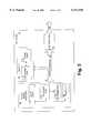
- FIG. 3is a simplified schematic view of a DSL device of FIG. 2 employing the automatic distortion detection method and apparatus of the present invention
- FIGS. 4A-4Care simplified illustrations of the signal level and frequency placement of POTS band signals and DSL band signals on the two-wire communications channel of FIG. 1;
- FIG. 5is a simplified illustration of the signal level and frequency placement of POTS band signals, DSL band signals, and distortion on the two-wire communications channel of FIG. 2, in which a phone filter is not used;
- FIG. 6is a simplified illustration of the signals of FIG. 5 measured at the conventional telephone interface, where a phone filter has been used to reduce the level of the DSL signal, and hence the distortion;
- FIG. 7is a simplified illustration of the signals of FIG. 5 measured at the DSL device, where a phone filter has been used to reduce the level of the DSL signal, and hence the distortion;
- FIGS. 8A and 8Bare simplified illustrations of the correlation of the DSL signal and the distortion components of that signal when the DSL signal is time-varied according to the present invention.
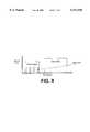
- FIG. 9is a simplified illustration of the signal level and frequency placement of POTS band signals, DSL band signals, and distortion on the two-wire communications channel of FIG. 2 when the DSL signal is time-varied according to the present invention.
- FIG. 10is a flow chart illustrating the operation of the method and apparatus of the present invention for automatically detecting and measuring distortion in a DSL system in order to determine whether the distortion is within acceptable levels.
- the present inventioncan be implemented in software, hardware, firmware, or a combination thereof.
- the elements of the present inventionare implemented in software that is stored in a memory and that configures and drives a suitable digital signal processor (DSP) situated in the respective DSL-type device.
- DSPdigital signal processor
- the foregoing softwarecan be stored on any computer-readable medium for use by or in connection with any suitable computer-related system or method.
- a computer-readable mediumis an electronic, magnetic, optical, electromagnetic, infrared, or semiconductor system, apparatus, device, or propagation medium.
- the computer-readable mediumwould include the following: an electrical connection (electronic) having one or more wires, a portable computer diskette (magnetic), a random access memory (RAM) (magnetic), a read-only memory (ROM) (magnetic), an erasable programmable read-only memory (EPROM or Flash memory) (magnetic), an optical fiber (optical), and a portable compact disc read-only memory (CD-ROM) (optical).
- an electrical connectionelectronic having one or more wires
- a portable computer diskettemagnetic
- RAMrandom access memory
- ROMread-only memory
- EPROM or Flash memoryerasable programmable read-only memory
- CD-ROMportable compact disc read-only memory
- the computer readable mediumcould even be paper or another suitable medium upon which the program is printed, as the program can be electronically captured, via for instance optical scanning of the paper or other medium, then compiled, interpreted or otherwise processed in a suitable manner if necessary, and then stored in a computer memory.
- FIG. 1is a schematic view illustrating a prior art communications environment 11.
- Communications channel 14is a conventional two-wire communications system that typically connects a telephone company central office location 12 to a remote user location 24.
- Remote user location 24is typically a residential or business location and includes POTS devices such as telephone 17, dial modem 18, and user device 21, as well as DSL devices, such as DSL modem 38 and user device 23.
- a POTS splitter 16is employed to connect the telephone 17, dial modem 18, and DSL modem 38 to the communications channel 14.
- POTS splitter 16is required in this application in order to isolate the telephone 17 and dial modem 18 from the DSL modem 38.
- POTS splitter 16is typically located at remote location 24.
- the POTS splitter 16typically serves two purposes: (1) it attenuates the DSL signals so that they do not significantly appear at the input of the telephone 17 or dial modem 18, and (2) it attenuates the telephone 17 or dial modem 18 transmit signals so that they do not significantly appear at the input of the DSL modem 38.
- the POTS splitter 16attempts to attenuate the DSL modem 38 signals appearing at the telephone 17 or dial modem 18 input in the audio band to an inaudible level, and also attempts to attenuate DSL modem 38 signals above the audio band to a level low enough so that distortion in the telephone 17 or dial is modem 18 does not adversely affect their performance.
- FIG. 2is a schematic view of a multipoint communications environment 31 in which POTS devices 17 and 18, and DSL devices 33 and 38 operate.
- the DSL devices 33 and 38employ the automatic distortion detection and measurement method and apparatus of the present invention.
- communications environment 31does not include a POTS splitter.
- Optional phone filters 40 and 41may be used to reduce distortion, as discussed hereinafter.
- User location 36is connected to central office location 32 via communication channel 34.
- DSL device 33is located at central office location 32, while at least one DSL device 38 is located at the user location 36, which is remote from central office location 32.
- Communication channel 34is typically the two-wire communication channel that extends between a telephone company central office and a remote residential, business, or any other location served by local telephone service.
- Remote location 36may contain a plurality of remote DSL devices 38 connecting a plurality of user devices 23 to communication channel 34 via communication bus 39.
- Communication bus 39is illustratively the wiring infrastructure used throughout a remote location to connect remote DSL devices 38 to communication channel 34.
- remote location 36may contain conventional POTS devices 17 and 18.
- conventional telephone 17 and dial modem 18which is not shown in FIG.
- DSL device 33 and remote DSL devices 38employing the concepts and features of the automatic distortion detection and measuring apparatus and method of the present invention, it is possible in some instances to connect POTS devices 17 and 18 directly to communication channel 34 without experiencing audible distortion. If the distortion detection and measurement method and apparatus of the present invention indicates an unacceptable level of distortion at the output of DSL devices 38, optional phone filters 40 and 41 may be used to reduce the distortion at POTS devices 17 and 18 to acceptable levels.
- DSL device 38will transmit signals to the central office 32 of FIG. 2 over communication channel 34.
- central office 32will transmit signals to DSL device 38.
- DSL device 38contains conventional components as are known in the art of data communications.
- Digital signal processor (DSP) 55controls the operation of and includes transmitter 50 and receiver 56 of DSL device 38.
- DSP 55couples through logical interface 45 to line interface 44 to gain access to communication channel 34.
- gating logic 51, and distortion detection and measuring logic 53are also included in DSP 55 of DSL device 38, which enable DSL device 38 to perform the distortion detection and measurement functions of the present invention, as discussed hereinbelow.
- memory 60which also includes gating logic 51, and distortion detection and measuring logic 53.
- the logic of the present inventionis executed within DSP 55 and is therefore shown as residing in both memory 60 and DSP 55.
- the output (transmit) DSL signal of DSL device 38is passed to communication channel 34 (via logical interface 45 and line interface 44) from transmitter 50.
- Transmitter 50is controlled by gating logic 51, which varies the DSL signal according to a time sequence.
- the output of transmitter 50is a gated DSL output signal, which is a time-varied representation of the original nongated DSL transmit signal.
- Distortion detection and measuring logic 53is coupled to line interface 44, as well as being correlated with the time sequence of gating logic 51.
- distortion detection and is measuring logic 53may also reside in central DSL device 33 of FIG. 2. However, for simplicity, the present invention is described with reference to remote DSL device 38.
- Gating logic 51, and distortion detection and measuring logic 53may be configured in software, hardware, firmware, or a combination thereof.
- gating logic 51may be implemented in hardware by such components as a modulator or a simple logic gate.
- Elements 51 and 53are used to implement DSP sequencing and correlation algorithms which are known in the art of data communications, and which are used to detect and measure distortion in the communications channel, as set forth in the following discussion. The following discussion assumes an off-hook telephone or dial modem. However, the concepts may be applied to on-hook devices as well.
- the following discussionillustrates how the apparatus of FIGS. 2 and 3 is used to detect and measure distortion in the communications channel.
- FIG. 4Aillustrates an ideal frequency placement of the telephone and dial modem signals (POTS band) and the DSL modem signals (DSL band) on the two-wire communications channel 14 of FIG. 1, wherein a POTS splitter has been used. Note that there is no overlap between the POTS band signals and the DSL band signals.
- FIG. 4Billustrates the signal at the DSL modem 38 interface wherein the POTS band signal has been filtered by the POTS splitter.
- FIG. 4Cillustrates the signal at the telephone 17 or dial modem 18 interface wherein the DSL signal has been filtered by the POTS splitter.
- FIG. 5illustrates the signal on the two-wire channel of the communications channel 34 of FIGS. 2 and 3, without the use of phone filters 40 and 41.
- the DSL signalcauses non-linear distortion at the telephone 17 or dial modem 18 interface.
- the DSL signalis a time-continuous signal (that is the envelope of the DSL signal is time-stationary)
- the distortion productsare also time-continuous and appear as wide band noise across all frequency bands.
- the net signal on the two-wire channelis composed of the POTS signal, the DSL signal, and the distortion signal. This distortion has a direct effect on the DSL performance of DSL device 38 due to the unwanted signal components in the DSL band.
- the distortionmore importantly is found to cause unacceptable audio noise in telephone 17 and reduces the performance of dial modem 18 due to the unwanted signal components in the dial modem signal.
- the distortion actually heard in a telephone speakermay exceed that indicated in FIG. 5 due to even further distortion within the telephone circuitry which is blocked from appearing at the telephone interface.
- the distortionalso may have frequency content that is different than that indicated in FIG. 5.
- FIG. 6shows the signal at the telephone 17 interface in the splitter-less DSL system of FIGS. 2 and 3 wherein optional phone filters 40 and 41 are used to reduce the amplitude of the DSL signal.
- the phone filterreduces the level of the DSL signal at the telephone which in turn reduces the distortion, typically by a reduction factor that is larger than the reduction factor of the DSL signal itself. As shown in FIG. 6, this reduces the level of distortion in both the POTS band and the DSL band.
- both the DSL signal envelope and the POTS signal envelope at the dial modem 18are time-stationary. That is, both signals are present at all times.
- a telephone voice signalis typically not time stationary because the POTS signals representing speech vary greatly in amplitude when viewed over seconds or minutes and the signal may be effectively absent.
- the POTS band signalmay at times be absent.
- FIG. 7illustrates the signal at DSL device 38 of FIGS. 2 and 3 in the presence of the effects illustrated in FIG. 6.
- both the POTS band signal components produced by POTS devices 17 and 18appear directly because the lowpass effect of phone filters 40 and 41 does not attenuate the POTS band.
- the DSL band distortion componentis reduced due to the lowpass filtering of the phone filters 40 and 41 and the DSL band signal level is increased because this signal is the unattenuated DSL signal.
- the distortion in the POTS bandis observable at the DSL device 38. Because the communication channel 34 passes the POTS band signals and the distortion components with equal attenuation, the distortion in the POTS band is also observable at DSL device 33.
- the POTS band signal component due to telephone audio or due to a dial modemis not practically separable from the POTS band distortion component because the distortion component, which is originally caused by the DSL signal, is smaller in amplitude than the telephone audio or dial modem component.
- the DSL deviceto correlate the distortion component with a DSL signal so that it can be extracted.
- a possible exception that would allow detectionwould be to measure the distortion component when a telephone signal is silent. This is impractical, however, because there is no guarantee of silence and because the level of distortion to be measured is very small and not dissimilar to the amplitude of signals due to telephone background noise.
- the distortions illustrated in FIGS. 5 through 7are due to the time stationary DSL signals. However, if the signal envelope of the DSL signals is varied with time, the DSL signals become non-stationary. The non-linear distortion caused by such non-stationary signals at a POTS device, such as a telephone or dial modem, is fundamentally different from the distortion that results from time stationary DSL signals.
- the nonlinear distortion components at the telephone or dial modem interfaceare correlated to that sequence.
- the DSL transmit signalsare time-varied by gating the output (transmit) signals of the DSL device on and off. Gating of the DSL signals according to a time sequence causes nonlinear distortion components at the telephone or dial modem interface that are correlated to the time sequence and in fact occur coincident in time with the gating.
- Such gatingcan be applied to a standard DSL signal in a (short duration) distortion test mode wherein measurement takes place at the sacrifice of data communication.
- gatingmay be inherent in certain DSL signaling, such as half duplex signaling, in which case non-interruptive and adaptive measurement can take place.
- the DSL signalis on for some duration less than 2 msec and off for the remainder of the 2 msec, such sequence repeating continuously, as illustrated in FIG. 8A.
- Each burst of DSL signalcauses via non-linear distortion in the telephone or dial modem a momentary change in the distortion component ("DC") signal at the telephone or dial modem interface during each burst, as illustrated in FIG. 8B.
- DCdistortion component
- FIG. 8Brepresents a simplified illustration of the distortion components.
- the distortion componentswill be more complex than the DC shown in FIG. 8B.
- the DC valuemay be expected to tend toward zero due to the highpass nature of the telephone or dial modem interface or contain higher frequency components.
- the polaritymay be reversed.
- the distortion components for the 500 Hz gating exampleinclude discrete line spectra at multiples of 500 Hz.
- the amplitude of the line spectradirectly corresponds with the overall level of distortion.
- the gating sequencemay be correlated with the "DC" distortion components using conventional techniques to detect the presence and the magnitude of the distortion.
- the magnitude of the POTS band signal at the DSL modem interfacecan be sampled and measured for a short time period after the beginning of every DSL signal burst, and measurement can be made over several or many bursts to accomplish correlation. It should also be clear that it is not necessary for the gating to be periodic. That is, even random DSL signal bursts allow detection and measurement of the distortion.
- the background audio levelshould be perhaps -50 dBm, maximum. It should be possible to detect and measure distortion components above -70 dBm with a detection assurance on the order of around 12 dB. This implies correlation signal-to-noise ratio (SNR) improvement of 32 dB (40 times) is needed, requiring correlation of about 1626 samples. For 1 msec DSL bursts at a rate of 500 Hz, it is reasonable to obtain 8 independent samples per burst (0.001 * 8000 Hz) and thus 4000 correlation samples in one second. The above -70 dBm distortion could be measured in about 0.4 seconds.
- SNRsignal-to-noise ratio
- the large distortion expected without a POTS filter with a large DSL signal levelmay result in distortion components at a level of at least -50 dBm, requiring correlation SNR improvement of 12 dB (16 times). This can be accomplished in perhaps 4 msec.
- the DSL signalis both transmitted and detected at the user's DSL device, such as DSL device 38 in FIG. 2.
- the distortionis also visible at other DSL devices in the system, as is detection of the gating sequence.
- detection of the distortioncan be accomplished at a DSL device remote from the transmitting DSL device, such as DSL device 33 in FIG. 2.
- each blockrepresents a module, segment, or portion of code, which comprises one or more executable instructions for implementing the specified logical function(s). It should also be noted that in some alternative implementations, the functions noted in the blocks may occur out of the order noted in FIG. 10.
- the present inventionfunctions as follows: in step 101, the DSL device transmits a gated DSL signal onto the communication channel.
- step 102the POTS band signal level is measured at the DSL device during the time in which the DSL signal is gated "off", and the average POTS band signal level during the "off” period is recorded.
- step 103the POTS band signal level is measured at the DSL device during the time period in which the DSL signal is gated "on”, and the average POTS band signal level during the "on” period is recorded.
- step 105the ratio of the POTS band signal level during the "on" period to the POTS band signal level during the "off” period is determined.
- the ratio determined in step 105represents the degree to which the POTS band distortion is higher during DSL transmission.
- steps 107 and 108the ratio determined in step 105 is compared to a threshold level of acceptable audio noise, which is determined empirically, such as by audio sound measurements. This threshold indicates the ratio above which unacceptable distortion is expected from the POTS devices in the presence of the DSL transmit signal.
- step 107if the ratio determined in step 105 is below the threshold, the distortion caused by the DSL level at the telephone is acceptable, and there is no need to add a phone filter.
- step 108if the ratio determined in step 105 is above the threshold, the distortion caused by the DSL level at the telephone is unacceptable, which indicates the need to add a phone filter.
- the DSLis not half-duplex, then the measurement illustrated in FIG. 10 will disrupt normal data communication, so it will be necessary to enter a test mode to make the measurements. If the DSL is half-duplex, communication need not be interrupted, although it may be preferable to enter a test mode in order to reduce test time. In either case, when the test mode is entered, the DSL is suitably configured and the appropriate measurements are made.
- distortioncan be detected and measured at either a local or remote DSL device to determine whether the distorting effects of the DSL device transmit signal warrant the incorporation of a phone filter at the interface to each POTS-type device in the system.
Landscapes
- Engineering & Computer Science (AREA)
- Signal Processing (AREA)
- Telephonic Communication Services (AREA)
Abstract
Description
Claims (19)
Priority Applications (1)
| Application Number | Priority Date | Filing Date | Title |
|---|---|---|---|
| US09/239,636US6111936A (en) | 1998-01-28 | 1999-01-28 | Method and apparatus for automatically detecting and measuring distortion in a DSL system |
Applications Claiming Priority (2)
| Application Number | Priority Date | Filing Date | Title |
|---|---|---|---|
| US7279298P | 1998-01-28 | 1998-01-28 | |
| US09/239,636US6111936A (en) | 1998-01-28 | 1999-01-28 | Method and apparatus for automatically detecting and measuring distortion in a DSL system |
Publications (1)
| Publication Number | Publication Date |
|---|---|
| US6111936Atrue US6111936A (en) | 2000-08-29 |
Family
ID=26753751
Family Applications (1)
| Application Number | Title | Priority Date | Filing Date |
|---|---|---|---|
| US09/239,636Expired - LifetimeUS6111936A (en) | 1998-01-28 | 1999-01-28 | Method and apparatus for automatically detecting and measuring distortion in a DSL system |
Country Status (1)
| Country | Link |
|---|---|
| US (1) | US6111936A (en) |
Cited By (69)
| Publication number | Priority date | Publication date | Assignee | Title |
|---|---|---|---|---|
| US6396912B1 (en)* | 1999-07-30 | 2002-05-28 | 3Com Corporation | Method and system for connecting multiple DSL modems to a telephone line |
| WO2002011409A3 (en)* | 2000-07-28 | 2002-06-06 | Legerity Inc | Device and method for determining characteristics of a digital subscriber line |
| US6430219B1 (en)* | 1997-10-03 | 2002-08-06 | Conexant Systems, Inc. | Method of and apparatus for performing line characterization in a subscriber line communication system |
| US6445733B1 (en) | 1997-10-03 | 2002-09-03 | Conexant Systems, Inc. | Method of and apparatus for performing line characterization in a non-idle mode in a subscriber line communication system |
| US20020133612A1 (en)* | 2001-03-16 | 2002-09-19 | Robert Depelteau | Network file sharing method and system |
| US6487241B1 (en)* | 1999-11-22 | 2002-11-26 | Advanced Micro Devices, Inc. | Method and apparatus employing cutback probe |
| US6493435B1 (en)* | 2000-04-06 | 2002-12-10 | Detection Systems, Inc. | Alarm system interface |
| US20020188731A1 (en)* | 2001-05-10 | 2002-12-12 | Sergey Potekhin | Control unit for multipoint multimedia/audio system |
| DE10203221A1 (en)* | 2002-01-28 | 2003-08-21 | Siemens Ag | Device and method for avoiding retrain processes with integrated voice and xDSL data transmission #### |
| US6647058B1 (en)* | 1997-06-23 | 2003-11-11 | Paradyne Corporation | Performance customization system and process for optimizing XDSL performance |
| US20040022272A1 (en)* | 2002-03-01 | 2004-02-05 | Jeffrey Rodman | System and method for communication channel and device control via an existing audio channel |
| US6690721B1 (en)* | 2000-01-07 | 2004-02-10 | 3Com Corporation | Method for asymmetric digital subscriber line modem recovery from insufficient transmit power |
| US20040042510A1 (en)* | 2002-05-08 | 2004-03-04 | Bremer Gordon F. | Indirect DSL over loaded and unloaded loops |
| US6721394B1 (en)* | 1999-12-09 | 2004-04-13 | 3Com Corporation | Method for reducing noise from an asymmetric digital subscriber line modem |
| US6839383B1 (en) | 2000-03-10 | 2005-01-04 | Cisco Technology, Inc. | Method and system for testing a digital subscriber line modem |
| US20050041753A1 (en)* | 2003-08-21 | 2005-02-24 | Aware, Inc. | Nonlinear device detection |
| US20050123028A1 (en)* | 2003-12-07 | 2005-06-09 | Adaptive Spectrum And Signal Alignment, Inc. | Adaptive margin and band control |
| US20050213726A1 (en)* | 2001-12-31 | 2005-09-29 | Polycom, Inc. | Conference bridge which transfers control information embedded in audio information between endpoints |
| US20050212908A1 (en)* | 2001-12-31 | 2005-09-29 | Polycom, Inc. | Method and apparatus for combining speakerphone and video conference unit operations |
| US20050213725A1 (en)* | 2001-12-31 | 2005-09-29 | Polycom, Inc. | Speakerphone transmitting control information embedded in audio information through a conference bridge |
| US20050213735A1 (en)* | 2000-12-26 | 2005-09-29 | Polycom, Inc. | Speakerphone transmitting URL information to a remote device |
| US20050213517A1 (en)* | 2000-12-26 | 2005-09-29 | Polycom, Inc. | Conference endpoint controlling audio volume of a remote device |
| US20050213737A1 (en)* | 2000-12-26 | 2005-09-29 | Polycom, Inc. | Speakerphone transmitting password information to a remote device |
| US20050213732A1 (en)* | 2001-12-31 | 2005-09-29 | Polycom, Inc. | Conference bridge which decodes and responds to control information embedded in audio information |
| US20050213739A1 (en)* | 2001-05-10 | 2005-09-29 | Polycom, Inc. | Conference endpoint controlling functions of a remote device |
| US20050213730A1 (en)* | 2000-12-26 | 2005-09-29 | Polycom, Inc. | Conference endpoint instructing conference bridge to dial phone number |
| US20050213731A1 (en)* | 2001-12-31 | 2005-09-29 | Polycom, Inc. | Conference endpoint instructing conference bridge to mute participants |
| US20050213728A1 (en)* | 2001-12-31 | 2005-09-29 | Polycom, Inc. | Conference endpoint instructing a remote device to establish a new connection |
| US20050213729A1 (en)* | 2000-12-26 | 2005-09-29 | Polycom,Inc. | Speakerphone using a secure audio connection to initiate a second secure connection |
| US6988212B1 (en) | 2000-09-29 | 2006-01-17 | Hewlett-Packard Development Company, L.P. | Method and system for adaptive power control in a networking system |
| US7003078B2 (en) | 1999-01-29 | 2006-02-21 | Sbc Knowledge Ventures, Lp | Method and apparatus for telephone line testing |
| US7006445B1 (en) | 1997-07-07 | 2006-02-28 | Legerity, Inc. | Device and method for determining characteristics of a digital subscriber line |
| US20060198430A1 (en)* | 2005-03-03 | 2006-09-07 | Adaptive Spectrum And Signal Alignment, Inc. | DSL state and line profile control |
| US20070047624A1 (en)* | 2005-06-08 | 2007-03-01 | Polycom, Inc | Mixed voice and spread spectrum data signaling with enhanced concealment of data |
| US20070140456A1 (en)* | 2001-12-31 | 2007-06-21 | Polycom, Inc. | Method and apparatus for wideband conferencing |
| US7239687B1 (en)* | 1998-01-29 | 2007-07-03 | Stmicroelectronics N.V. | Telecommunications |
| US20070183324A1 (en)* | 2006-02-06 | 2007-08-09 | Cuberson Russel D | Methods, systems, and computer program products for providing supported DSL communications features as selections |
| CN100385894C (en)* | 2002-02-21 | 2008-04-30 | 友讯科技股份有限公司 | Mobile VDSL signal line tester |
| US20080143819A1 (en)* | 2004-04-16 | 2008-06-19 | Polycom, Inc. | Conference link between a speakerphone and a video conference unit |
| US20080267055A1 (en)* | 2007-04-25 | 2008-10-30 | Thomas Starr | Methods and apparatus to cancel noise using a common reference wire-pair |
| US7457250B2 (en)* | 1998-04-10 | 2008-11-25 | Chrimar Systems, Inc. | System for communicating with electronic equipment |
| US20080298444A1 (en)* | 2005-10-04 | 2008-12-04 | Cioffi John M | Dsl System |
| US7593394B2 (en) | 2000-04-18 | 2009-09-22 | Mosaid Technologies Incorporated | Telephone communication system over a single telephone line |
| US7633966B2 (en) | 2000-04-19 | 2009-12-15 | Mosaid Technologies Incorporated | Network combining wired and non-wired segments |
| US7680255B2 (en) | 2001-07-05 | 2010-03-16 | Mosaid Technologies Incorporated | Telephone outlet with packet telephony adaptor, and a network using same |
| US7686653B2 (en) | 2003-09-07 | 2010-03-30 | Mosaid Technologies Incorporated | Modular outlet |
| US7702095B2 (en) | 2003-01-30 | 2010-04-20 | Mosaid Technologies Incorporated | Method and system for providing DC power on local telephone lines |
| US7715534B2 (en) | 2000-03-20 | 2010-05-11 | Mosaid Technologies Incorporated | Telephone outlet for implementing a local area network over telephone lines and a local area network using such outlets |
| US7742588B2 (en) | 2001-12-31 | 2010-06-22 | Polycom, Inc. | Speakerphone establishing and using a second connection of graphics information |
| US7746905B2 (en) | 2003-03-13 | 2010-06-29 | Mosaid Technologies Incorporated | Private telephone network connected to more than one public network |
| US7796565B2 (en) | 2005-06-08 | 2010-09-14 | Polycom, Inc. | Mixed voice and spread spectrum data signaling with multiplexing multiple users with CDMA |
| US7830955B2 (en) | 2005-07-10 | 2010-11-09 | Adaptive Spectrum & Signal Alignment, Inc. | Adaptive margin and band control |
| US20110053528A1 (en)* | 2008-01-29 | 2011-03-03 | Aware, Inc. | Method and system for detecting non-linear devices |
| US20110051906A1 (en)* | 2003-12-07 | 2011-03-03 | Cioffi John M | Adaptive margin and band control |
| US7965735B2 (en) | 1998-07-28 | 2011-06-21 | Mosaid Technologies Incorporated | Local area network of serial intelligent cells |
| US7990908B2 (en) | 2002-11-13 | 2011-08-02 | Mosaid Technologies Incorporated | Addressable outlet, and a network using the same |
| US8023580B2 (en) | 1997-12-05 | 2011-09-20 | Bremer Gordon F | System and method of communication using at least two modulation methods |
| US8102984B2 (en) | 2001-12-31 | 2012-01-24 | Polycom Inc. | Speakerphone and conference bridge which receive and provide participant monitoring information |
| US8126029B2 (en) | 2005-06-08 | 2012-02-28 | Polycom, Inc. | Voice interference correction for mixed voice and spread spectrum data signaling |
| US8144854B2 (en) | 2001-12-31 | 2012-03-27 | Polycom Inc. | Conference bridge which detects control information embedded in audio information to prioritize operations |
| US8223942B2 (en) | 2001-12-31 | 2012-07-17 | Polycom, Inc. | Conference endpoint requesting and receiving billing information from a conference bridge |
| US8351582B2 (en) | 1999-07-20 | 2013-01-08 | Mosaid Technologies Incorporated | Network for telephony and data communication |
| US8582598B2 (en) | 1999-07-07 | 2013-11-12 | Mosaid Technologies Incorporated | Local area network for distributing data communication, sensing and control signals |
| US8611528B2 (en) | 2004-02-16 | 2013-12-17 | Mosaid Technologies Incorporated | Outlet add-on module |
| US8705719B2 (en) | 2001-12-31 | 2014-04-22 | Polycom, Inc. | Speakerphone and conference bridge which receive and provide participant monitoring information |
| US8976712B2 (en) | 2001-05-10 | 2015-03-10 | Polycom, Inc. | Speakerphone and conference bridge which request and perform polling operations |
| US9130655B2 (en) | 2009-11-30 | 2015-09-08 | Broadcom Corporation | Methods and systems for detecting metallic faults affecting communications links |
| US9432172B2 (en) | 1997-12-05 | 2016-08-30 | Rembrandt Wireless Technologies, Lp | System and method of communication using at least two modulation methods |
| US10986164B2 (en) | 2004-01-13 | 2021-04-20 | May Patents Ltd. | Information device |
Citations (13)
| Publication number | Priority date | Publication date | Assignee | Title |
|---|---|---|---|---|
| US4918623A (en)* | 1985-10-04 | 1990-04-17 | Codex Corporation | Testing the performance of a communication line between two modems using modem processor |
| US5166954A (en)* | 1991-03-05 | 1992-11-24 | At&T Bell Laboratories | Adaptive system for measuring the broadband signal-to-noise ratio of a transmission channel |
| US5397992A (en)* | 1991-08-22 | 1995-03-14 | Sage Instruments | Measuring a circuit delay |
| US5475315A (en)* | 1991-09-20 | 1995-12-12 | Audio Precision, Inc. | Method and apparatus for fast response and distortion measurement |
| US5515398A (en)* | 1994-03-15 | 1996-05-07 | U.S. Robotics, Inc. | Modem line probing signal techniques |
| US5579369A (en)* | 1993-12-23 | 1996-11-26 | Lucent Technologies Inc. | Facility type determination technique |
| US5598455A (en)* | 1990-09-17 | 1997-01-28 | Raychem Corporation | Alarm and test system for a digital added main line |
| US5652782A (en)* | 1993-10-27 | 1997-07-29 | Canon Inc. | Digital telephone overcoming international incompatibilities |
| US5672974A (en)* | 1996-01-18 | 1997-09-30 | Convex Corporation | Returned reference compatible, straightaway envelope delay measurement instrument and method |
| US5805669A (en)* | 1996-12-30 | 1998-09-08 | Paradyne Corporation | Rate adaptaptive subscriber line ("RADSL") modem and method of operation |
| US5881130A (en)* | 1997-09-15 | 1999-03-09 | Teradyne, Inc. | Fast and noise-insensitive load status detection |
| US6014425A (en)* | 1997-02-26 | 2000-01-11 | Paradyne Corporation | Apparatus and method for qualifying telephones and other attached equipment for optimum DSL operation |
| US6038425A (en)* | 1998-08-03 | 2000-03-14 | Jeffrey; Ross A. | Audio/video signal redistribution system |
- 1999
- 1999-01-28USUS09/239,636patent/US6111936A/ennot_activeExpired - Lifetime
Patent Citations (14)
| Publication number | Priority date | Publication date | Assignee | Title |
|---|---|---|---|---|
| US4918623A (en)* | 1985-10-04 | 1990-04-17 | Codex Corporation | Testing the performance of a communication line between two modems using modem processor |
| US5598455A (en)* | 1990-09-17 | 1997-01-28 | Raychem Corporation | Alarm and test system for a digital added main line |
| US5166954A (en)* | 1991-03-05 | 1992-11-24 | At&T Bell Laboratories | Adaptive system for measuring the broadband signal-to-noise ratio of a transmission channel |
| US5397992A (en)* | 1991-08-22 | 1995-03-14 | Sage Instruments | Measuring a circuit delay |
| US5475315A (en)* | 1991-09-20 | 1995-12-12 | Audio Precision, Inc. | Method and apparatus for fast response and distortion measurement |
| US5649304A (en)* | 1991-09-20 | 1997-07-15 | Audio Precision, Inc. | Method and apparatus for communicating auxiliary information in a measurement signal |
| US5652782A (en)* | 1993-10-27 | 1997-07-29 | Canon Inc. | Digital telephone overcoming international incompatibilities |
| US5579369A (en)* | 1993-12-23 | 1996-11-26 | Lucent Technologies Inc. | Facility type determination technique |
| US5515398A (en)* | 1994-03-15 | 1996-05-07 | U.S. Robotics, Inc. | Modem line probing signal techniques |
| US5672974A (en)* | 1996-01-18 | 1997-09-30 | Convex Corporation | Returned reference compatible, straightaway envelope delay measurement instrument and method |
| US5805669A (en)* | 1996-12-30 | 1998-09-08 | Paradyne Corporation | Rate adaptaptive subscriber line ("RADSL") modem and method of operation |
| US6014425A (en)* | 1997-02-26 | 2000-01-11 | Paradyne Corporation | Apparatus and method for qualifying telephones and other attached equipment for optimum DSL operation |
| US5881130A (en)* | 1997-09-15 | 1999-03-09 | Teradyne, Inc. | Fast and noise-insensitive load status detection |
| US6038425A (en)* | 1998-08-03 | 2000-03-14 | Jeffrey; Ross A. | Audio/video signal redistribution system |
Cited By (149)
| Publication number | Priority date | Publication date | Assignee | Title |
|---|---|---|---|---|
| US20040081233A1 (en)* | 1997-06-23 | 2004-04-29 | Gordon Bremer | Performance customization system and process for optimizing xDSL performance |
| US20100246598A1 (en)* | 1997-06-23 | 2010-09-30 | Paradyne Corporation | Performance Customization System and Process for Optimizing xDSL Performance |
| US9130654B2 (en) | 1997-06-23 | 2015-09-08 | Paradyne Corporation | Performance customization system and process for optimizing xDSL performance |
| US7916776B2 (en) | 1997-06-23 | 2011-03-29 | Paradyne Corporation | Performance customization system and process for optimizing xDSL performance |
| US6647058B1 (en)* | 1997-06-23 | 2003-11-11 | Paradyne Corporation | Performance customization system and process for optimizing XDSL performance |
| US7006445B1 (en) | 1997-07-07 | 2006-02-28 | Legerity, Inc. | Device and method for determining characteristics of a digital subscriber line |
| US6430219B1 (en)* | 1997-10-03 | 2002-08-06 | Conexant Systems, Inc. | Method of and apparatus for performing line characterization in a subscriber line communication system |
| US6445733B1 (en) | 1997-10-03 | 2002-09-03 | Conexant Systems, Inc. | Method of and apparatus for performing line characterization in a non-idle mode in a subscriber line communication system |
| US8023580B2 (en) | 1997-12-05 | 2011-09-20 | Bremer Gordon F | System and method of communication using at least two modulation methods |
| US8457228B2 (en) | 1997-12-05 | 2013-06-04 | Gordon F. Bremer | System and method of communication using at least two modulation methods |
| US9432172B2 (en) | 1997-12-05 | 2016-08-30 | Rembrandt Wireless Technologies, Lp | System and method of communication using at least two modulation methods |
| US7239687B1 (en)* | 1998-01-29 | 2007-07-03 | Stmicroelectronics N.V. | Telecommunications |
| US8942107B2 (en) | 1998-04-10 | 2015-01-27 | Chrimar Systems, Inc. | Piece of ethernet terminal equipment |
| US9049019B2 (en) | 1998-04-10 | 2015-06-02 | Chrimar Systems, Inc. | Network equipment and optional tether |
| US9019838B2 (en) | 1998-04-10 | 2015-04-28 | Chrimar Systems, Inc. | Central piece of network equipment |
| US8902760B2 (en) | 1998-04-10 | 2014-12-02 | Chrimar Systems, Inc. | Network system and optional tethers |
| US9812825B2 (en) | 1998-04-10 | 2017-11-07 | Chrimar Systems, Inc. | Ethernet device |
| US7457250B2 (en)* | 1998-04-10 | 2008-11-25 | Chrimar Systems, Inc. | System for communicating with electronic equipment |
| US8155012B2 (en) | 1998-04-10 | 2012-04-10 | Chrimar Systems, Inc. | System and method for adapting a piece of terminal equipment |
| US7965735B2 (en) | 1998-07-28 | 2011-06-21 | Mosaid Technologies Incorporated | Local area network of serial intelligent cells |
| US8885659B2 (en) | 1998-07-28 | 2014-11-11 | Conversant Intellectual Property Management Incorporated | Local area network of serial intelligent cells |
| US8325636B2 (en) | 1998-07-28 | 2012-12-04 | Mosaid Technologies Incorporated | Local area network of serial intelligent cells |
| US7986708B2 (en) | 1998-07-28 | 2011-07-26 | Mosaid Technologies Incorporated | Local area network of serial intelligent cells |
| US8867523B2 (en) | 1998-07-28 | 2014-10-21 | Conversant Intellectual Property Management Incorporated | Local area network of serial intelligent cells |
| US8885660B2 (en) | 1998-07-28 | 2014-11-11 | Conversant Intellectual Property Management Incorporated | Local area network of serial intelligent cells |
| US8908673B2 (en) | 1998-07-28 | 2014-12-09 | Conversant Intellectual Property Management Incorporated | Local area network of serial intelligent cells |
| US8737572B2 (en) | 1999-01-29 | 2014-05-27 | AT&T Intellectual Properties, I, L.P. | Method and apparatus for transmission line testing |
| US9426282B2 (en) | 1999-01-29 | 2016-08-23 | At&T Intellectual Property I, L.P. | Method and apparatus for transmission line testing |
| US20080089400A1 (en)* | 1999-01-29 | 2008-04-17 | At&T Knowledge Ventures, L.P. | Method and Apparatus for Transmission Line Testing |
| US7003078B2 (en) | 1999-01-29 | 2006-02-21 | Sbc Knowledge Ventures, Lp | Method and apparatus for telephone line testing |
| US8582598B2 (en) | 1999-07-07 | 2013-11-12 | Mosaid Technologies Incorporated | Local area network for distributing data communication, sensing and control signals |
| US8351582B2 (en) | 1999-07-20 | 2013-01-08 | Mosaid Technologies Incorporated | Network for telephony and data communication |
| US8929523B2 (en) | 1999-07-20 | 2015-01-06 | Conversant Intellectual Property Management Inc. | Network for telephony and data communication |
| US6396912B1 (en)* | 1999-07-30 | 2002-05-28 | 3Com Corporation | Method and system for connecting multiple DSL modems to a telephone line |
| US6487241B1 (en)* | 1999-11-22 | 2002-11-26 | Advanced Micro Devices, Inc. | Method and apparatus employing cutback probe |
| US6721394B1 (en)* | 1999-12-09 | 2004-04-13 | 3Com Corporation | Method for reducing noise from an asymmetric digital subscriber line modem |
| US6690721B1 (en)* | 2000-01-07 | 2004-02-10 | 3Com Corporation | Method for asymmetric digital subscriber line modem recovery from insufficient transmit power |
| US6839383B1 (en) | 2000-03-10 | 2005-01-04 | Cisco Technology, Inc. | Method and system for testing a digital subscriber line modem |
| US8855277B2 (en) | 2000-03-20 | 2014-10-07 | Conversant Intellectual Property Managment Incorporated | Telephone outlet for implementing a local area network over telephone lines and a local area network using such outlets |
| US7715534B2 (en) | 2000-03-20 | 2010-05-11 | Mosaid Technologies Incorporated | Telephone outlet for implementing a local area network over telephone lines and a local area network using such outlets |
| US8363797B2 (en) | 2000-03-20 | 2013-01-29 | Mosaid Technologies Incorporated | Telephone outlet for implementing a local area network over telephone lines and a local area network using such outlets |
| US6493435B1 (en)* | 2000-04-06 | 2002-12-10 | Detection Systems, Inc. | Alarm system interface |
| US8000349B2 (en) | 2000-04-18 | 2011-08-16 | Mosaid Technologies Incorporated | Telephone communication system over a single telephone line |
| US8223800B2 (en) | 2000-04-18 | 2012-07-17 | Mosaid Technologies Incorporated | Telephone communication system over a single telephone line |
| US7593394B2 (en) | 2000-04-18 | 2009-09-22 | Mosaid Technologies Incorporated | Telephone communication system over a single telephone line |
| US8559422B2 (en) | 2000-04-18 | 2013-10-15 | Mosaid Technologies Incorporated | Telephone communication system over a single telephone line |
| US8873575B2 (en) | 2000-04-19 | 2014-10-28 | Conversant Intellectual Property Management Incorporated | Network combining wired and non-wired segments |
| US7633966B2 (en) | 2000-04-19 | 2009-12-15 | Mosaid Technologies Incorporated | Network combining wired and non-wired segments |
| US8848725B2 (en) | 2000-04-19 | 2014-09-30 | Conversant Intellectual Property Management Incorporated | Network combining wired and non-wired segments |
| US8982903B2 (en) | 2000-04-19 | 2015-03-17 | Conversant Intellectual Property Management Inc. | Network combining wired and non-wired segments |
| US8867506B2 (en) | 2000-04-19 | 2014-10-21 | Conversant Intellectual Property Management Incorporated | Network combining wired and non-wired segments |
| US8982904B2 (en) | 2000-04-19 | 2015-03-17 | Conversant Intellectual Property Management Inc. | Network combining wired and non-wired segments |
| US8873586B2 (en) | 2000-04-19 | 2014-10-28 | Conversant Intellectual Property Management Incorporated | Network combining wired and non-wired segments |
| WO2002011409A3 (en)* | 2000-07-28 | 2002-06-06 | Legerity Inc | Device and method for determining characteristics of a digital subscriber line |
| US6988212B1 (en) | 2000-09-29 | 2006-01-17 | Hewlett-Packard Development Company, L.P. | Method and system for adaptive power control in a networking system |
| US20050213730A1 (en)* | 2000-12-26 | 2005-09-29 | Polycom, Inc. | Conference endpoint instructing conference bridge to dial phone number |
| US20050213729A1 (en)* | 2000-12-26 | 2005-09-29 | Polycom,Inc. | Speakerphone using a secure audio connection to initiate a second secure connection |
| US8948059B2 (en) | 2000-12-26 | 2015-02-03 | Polycom, Inc. | Conference endpoint controlling audio volume of a remote device |
| US8964604B2 (en) | 2000-12-26 | 2015-02-24 | Polycom, Inc. | Conference endpoint instructing conference bridge to dial phone number |
| US9001702B2 (en) | 2000-12-26 | 2015-04-07 | Polycom, Inc. | Speakerphone using a secure audio connection to initiate a second secure connection |
| US20050213737A1 (en)* | 2000-12-26 | 2005-09-29 | Polycom, Inc. | Speakerphone transmitting password information to a remote device |
| US20050213517A1 (en)* | 2000-12-26 | 2005-09-29 | Polycom, Inc. | Conference endpoint controlling audio volume of a remote device |
| US20050213735A1 (en)* | 2000-12-26 | 2005-09-29 | Polycom, Inc. | Speakerphone transmitting URL information to a remote device |
| US8977683B2 (en)* | 2000-12-26 | 2015-03-10 | Polycom, Inc. | Speakerphone transmitting password information to a remote device |
| US7864938B2 (en) | 2000-12-26 | 2011-01-04 | Polycom, Inc. | Speakerphone transmitting URL information to a remote device |
| US20020133612A1 (en)* | 2001-03-16 | 2002-09-19 | Robert Depelteau | Network file sharing method and system |
| US7103637B2 (en)* | 2001-03-16 | 2006-09-05 | Emc Corporation | Network file sharing method and system |
| US20050213739A1 (en)* | 2001-05-10 | 2005-09-29 | Polycom, Inc. | Conference endpoint controlling functions of a remote device |
| US20020188731A1 (en)* | 2001-05-10 | 2002-12-12 | Sergey Potekhin | Control unit for multipoint multimedia/audio system |
| US8805928B2 (en) | 2001-05-10 | 2014-08-12 | Polycom, Inc. | Control unit for multipoint multimedia/audio system |
| US8976712B2 (en) | 2001-05-10 | 2015-03-10 | Polycom, Inc. | Speakerphone and conference bridge which request and perform polling operations |
| US8934382B2 (en) | 2001-05-10 | 2015-01-13 | Polycom, Inc. | Conference endpoint controlling functions of a remote device |
| US7680255B2 (en) | 2001-07-05 | 2010-03-16 | Mosaid Technologies Incorporated | Telephone outlet with packet telephony adaptor, and a network using same |
| US8761186B2 (en) | 2001-07-05 | 2014-06-24 | Conversant Intellectual Property Management Incorporated | Telephone outlet with packet telephony adapter, and a network using same |
| US7769030B2 (en) | 2001-07-05 | 2010-08-03 | Mosaid Technologies Incorporated | Telephone outlet with packet telephony adapter, and a network using same |
| US8472593B2 (en) | 2001-07-05 | 2013-06-25 | Mosaid Technologies Incorporated | Telephone outlet with packet telephony adaptor, and a network using same |
| US20050213726A1 (en)* | 2001-12-31 | 2005-09-29 | Polycom, Inc. | Conference bridge which transfers control information embedded in audio information between endpoints |
| US8102984B2 (en) | 2001-12-31 | 2012-01-24 | Polycom Inc. | Speakerphone and conference bridge which receive and provide participant monitoring information |
| US8934381B2 (en) | 2001-12-31 | 2015-01-13 | Polycom, Inc. | Conference endpoint instructing a remote device to establish a new connection |
| US8705719B2 (en) | 2001-12-31 | 2014-04-22 | Polycom, Inc. | Speakerphone and conference bridge which receive and provide participant monitoring information |
| US8947487B2 (en) | 2001-12-31 | 2015-02-03 | Polycom, Inc. | Method and apparatus for combining speakerphone and video conference unit operations |
| US8582520B2 (en) | 2001-12-31 | 2013-11-12 | Polycom, Inc. | Method and apparatus for wideband conferencing |
| US7742588B2 (en) | 2001-12-31 | 2010-06-22 | Polycom, Inc. | Speakerphone establishing and using a second connection of graphics information |
| US8023458B2 (en) | 2001-12-31 | 2011-09-20 | Polycom, Inc. | Method and apparatus for wideband conferencing |
| US20050212908A1 (en)* | 2001-12-31 | 2005-09-29 | Polycom, Inc. | Method and apparatus for combining speakerphone and video conference unit operations |
| US8885523B2 (en) | 2001-12-31 | 2014-11-11 | Polycom, Inc. | Speakerphone transmitting control information embedded in audio information through a conference bridge |
| US8223942B2 (en) | 2001-12-31 | 2012-07-17 | Polycom, Inc. | Conference endpoint requesting and receiving billing information from a conference bridge |
| US7787605B2 (en) | 2001-12-31 | 2010-08-31 | Polycom, Inc. | Conference bridge which decodes and responds to control information embedded in audio information |
| US7978838B2 (en) | 2001-12-31 | 2011-07-12 | Polycom, Inc. | Conference endpoint instructing conference bridge to mute participants |
| US20070140456A1 (en)* | 2001-12-31 | 2007-06-21 | Polycom, Inc. | Method and apparatus for wideband conferencing |
| US20050213728A1 (en)* | 2001-12-31 | 2005-09-29 | Polycom, Inc. | Conference endpoint instructing a remote device to establish a new connection |
| US8144854B2 (en) | 2001-12-31 | 2012-03-27 | Polycom Inc. | Conference bridge which detects control information embedded in audio information to prioritize operations |
| US20050213731A1 (en)* | 2001-12-31 | 2005-09-29 | Polycom, Inc. | Conference endpoint instructing conference bridge to mute participants |
| US20050213732A1 (en)* | 2001-12-31 | 2005-09-29 | Polycom, Inc. | Conference bridge which decodes and responds to control information embedded in audio information |
| US20050213725A1 (en)* | 2001-12-31 | 2005-09-29 | Polycom, Inc. | Speakerphone transmitting control information embedded in audio information through a conference bridge |
| US20050078709A1 (en)* | 2002-01-28 | 2005-04-14 | Siemens Aktiengesellschaft | Device and method for avoiding retraining processes in integrated voice and xdsl data transmission |
| DE10203221A1 (en)* | 2002-01-28 | 2003-08-21 | Siemens Ag | Device and method for avoiding retrain processes with integrated voice and xDSL data transmission #### |
| CN100385894C (en)* | 2002-02-21 | 2008-04-30 | 友讯科技股份有限公司 | Mobile VDSL signal line tester |
| US20040022272A1 (en)* | 2002-03-01 | 2004-02-05 | Jeffrey Rodman | System and method for communication channel and device control via an existing audio channel |
| US7821918B2 (en) | 2002-03-01 | 2010-10-26 | Polycom, Inc. | System and method for communication channel and device control via an existing audio channel |
| US20040042510A1 (en)* | 2002-05-08 | 2004-03-04 | Bremer Gordon F. | Indirect DSL over loaded and unloaded loops |
| US7471777B2 (en) | 2002-05-08 | 2008-12-30 | Summit Technology Systems, Lp | Indirect DSL over loaded and unloaded loops |
| US20090262911A1 (en)* | 2002-05-08 | 2009-10-22 | Bremer Gordon F | Repeaterless Backhaul |
| US20090262912A1 (en)* | 2002-05-08 | 2009-10-22 | Bremer Gordon F | Splitterless Communication |
| US7990908B2 (en) | 2002-11-13 | 2011-08-02 | Mosaid Technologies Incorporated | Addressable outlet, and a network using the same |
| US8107618B2 (en) | 2003-01-30 | 2012-01-31 | Mosaid Technologies Incorporated | Method and system for providing DC power on local telephone lines |
| US7702095B2 (en) | 2003-01-30 | 2010-04-20 | Mosaid Technologies Incorporated | Method and system for providing DC power on local telephone lines |
| US8787562B2 (en) | 2003-01-30 | 2014-07-22 | Conversant Intellectual Property Management Inc. | Method and system for providing DC power on local telephone lines |
| US8238328B2 (en) | 2003-03-13 | 2012-08-07 | Mosaid Technologies Incorporated | Telephone system having multiple distinct sources and accessories therefor |
| US7746905B2 (en) | 2003-03-13 | 2010-06-29 | Mosaid Technologies Incorporated | Private telephone network connected to more than one public network |
| CN1856987B (en)* | 2003-08-21 | 2011-06-01 | 阿瓦雷公司 | Nonlinear device detection |
| JP2007503172A (en)* | 2003-08-21 | 2007-02-15 | アウェア, インコーポレイテッド | Non-linear device detection |
| US20050041753A1 (en)* | 2003-08-21 | 2005-02-24 | Aware, Inc. | Nonlinear device detection |
| WO2005022877A1 (en) | 2003-08-21 | 2005-03-10 | Aware, Inc. | Nonlinear device detection |
| AU2010200127B2 (en)* | 2003-08-21 | 2012-12-20 | Aware, Inc. | Nonlinear device detection |
| US7580471B2 (en) | 2003-08-21 | 2009-08-25 | Aware, Inc. | Nonlinear device detection |
| AU2004302784B2 (en)* | 2003-08-21 | 2009-10-29 | Aware, Inc. | Nonlinear device detection |
| US20090268797A1 (en)* | 2003-08-21 | 2009-10-29 | Aware, Inc. | Nonlinear device detection |
| EP2288128A3 (en)* | 2003-08-21 | 2011-12-28 | Aware, Inc. | Nonlinear device detection |
| JP2010022026A (en)* | 2003-08-21 | 2010-01-28 | Aware Inc | Detection of nonlinear device |
| US7686653B2 (en) | 2003-09-07 | 2010-03-30 | Mosaid Technologies Incorporated | Modular outlet |
| US8031761B2 (en) | 2003-12-07 | 2011-10-04 | Adaptive Spectrum And Signal Alignment, Inc. | Adaptive margin and band control |
| US20050123028A1 (en)* | 2003-12-07 | 2005-06-09 | Adaptive Spectrum And Signal Alignment, Inc. | Adaptive margin and band control |
| US20110051906A1 (en)* | 2003-12-07 | 2011-03-03 | Cioffi John M | Adaptive margin and band control |
| US7558315B2 (en)* | 2003-12-07 | 2009-07-07 | Adaptive Spectrum And Signal Alignment, Inc. | Adaptive margin and band control in digital subscriber line (DSL) systems |
| US11032353B2 (en) | 2004-01-13 | 2021-06-08 | May Patents Ltd. | Information device |
| US10986164B2 (en) | 2004-01-13 | 2021-04-20 | May Patents Ltd. | Information device |
| US8611528B2 (en) | 2004-02-16 | 2013-12-17 | Mosaid Technologies Incorporated | Outlet add-on module |
| US8004556B2 (en) | 2004-04-16 | 2011-08-23 | Polycom, Inc. | Conference link between a speakerphone and a video conference unit |
| US20080143819A1 (en)* | 2004-04-16 | 2008-06-19 | Polycom, Inc. | Conference link between a speakerphone and a video conference unit |
| US7460588B2 (en) | 2005-03-03 | 2008-12-02 | Adaptive Spectrum And Signal Alignment, Inc. | Digital subscriber line (DSL) state and line profile control |
| US20060198430A1 (en)* | 2005-03-03 | 2006-09-07 | Adaptive Spectrum And Signal Alignment, Inc. | DSL state and line profile control |
| US7796565B2 (en) | 2005-06-08 | 2010-09-14 | Polycom, Inc. | Mixed voice and spread spectrum data signaling with multiplexing multiple users with CDMA |
| US8126029B2 (en) | 2005-06-08 | 2012-02-28 | Polycom, Inc. | Voice interference correction for mixed voice and spread spectrum data signaling |
| US8199791B2 (en) | 2005-06-08 | 2012-06-12 | Polycom, Inc. | Mixed voice and spread spectrum data signaling with enhanced concealment of data |
| US20070047624A1 (en)* | 2005-06-08 | 2007-03-01 | Polycom, Inc | Mixed voice and spread spectrum data signaling with enhanced concealment of data |
| US7830955B2 (en) | 2005-07-10 | 2010-11-09 | Adaptive Spectrum & Signal Alignment, Inc. | Adaptive margin and band control |
| US9203724B2 (en) | 2005-10-04 | 2015-12-01 | Adaptive Spectrum And Signal Alignment, Inc. | DSL system |
| US8009665B2 (en) | 2005-10-04 | 2011-08-30 | Assia, Inc. | DSL system |
| US20080298444A1 (en)* | 2005-10-04 | 2008-12-04 | Cioffi John M | Dsl System |
| US10581683B2 (en) | 2005-10-04 | 2020-03-03 | Assia Spe, Llc | DSL system |
| US20070183324A1 (en)* | 2006-02-06 | 2007-08-09 | Cuberson Russel D | Methods, systems, and computer program products for providing supported DSL communications features as selections |
| US8121029B2 (en)* | 2006-02-06 | 2012-02-21 | At&T Intellectual Property I, L.P. | Methods and systems for providing supported DSL communications features as selections |
| US20080267055A1 (en)* | 2007-04-25 | 2008-10-30 | Thomas Starr | Methods and apparatus to cancel noise using a common reference wire-pair |
| US20140036980A1 (en)* | 2008-01-29 | 2014-02-06 | Aware, Inc. | Method and system for detecting non-linear devices |
| US9270331B2 (en)* | 2008-01-29 | 2016-02-23 | Broadcom Corporation | Method and system for detecting non-linear devices |
| US8559532B2 (en) | 2008-01-29 | 2013-10-15 | Aware, Inc. | Method and system for detecting non-linear devices |
| US20110053528A1 (en)* | 2008-01-29 | 2011-03-03 | Aware, Inc. | Method and system for detecting non-linear devices |
| US9130655B2 (en) | 2009-11-30 | 2015-09-08 | Broadcom Corporation | Methods and systems for detecting metallic faults affecting communications links |
Similar Documents
| Publication | Publication Date | Title |
|---|---|---|
| US6111936A (en) | Method and apparatus for automatically detecting and measuring distortion in a DSL system | |
| US6154524A (en) | Method and apparatus for automatically and adaptively adjusting telephone audio quality and DSL data rate in a DSL system | |
| AU760141B2 (en) | Digital signal processor-based telephone test set analysing and displaying multiple signal parameter data for terminal mode and line monitor mode operation | |
| US5029204A (en) | Operational status controller for echo canceling | |
| US5459781A (en) | Selectively activated dual tone multi-frequency detector | |
| US5646940A (en) | System for simultaneous analog and digital communications over an analog channel | |
| US5949864A (en) | Fraud prevention apparatus and method for performing policing functions for telephone services | |
| US6269160B1 (en) | Communications device including an improved CPE alerting signal (CAS) detection system | |
| CA2432935C (en) | Power cutback configuration of digital subscriber line transceivers using public switched telephone network signaling | |
| CA2484449C (en) | Method and system for processing tones to reduce false detection of fax and modem communications | |
| US5177781A (en) | Dialing pulse signature recognizing method and device | |
| US6795548B2 (en) | Method and system for data communication | |
| US6912269B2 (en) | Test unit for use at a network interface device | |
| US6263074B1 (en) | User programmable station set bass and treble control | |
| US7486724B2 (en) | Codec compensation techniques for channel analysis applications | |
| US6625175B1 (en) | Method and an arrangement for securing an ADSL connection | |
| EP0595483A1 (en) | Methods and apparatus for automatic switching between transmission of a spectrally redundant outgoing signal and reception of an incoming signal | |
| CN1206277A (en) | Digital signal processor-based telephone test set | |
| US6996218B2 (en) | FSK decoder for caller ID | |
| EP0889625A2 (en) | Digital signal processor-based telephone test set | |
| JP3247268B2 (en) | In-band signal communication system | |
| EP0724349A1 (en) | Method and device for remote transmission of a listening-in call on a telephone line | |
| GB2313017A (en) | Signalling in a communication system | |
| MXPA99011258A (en) | Digital signal processor-based telephone test set analyzing and displaying multiple signal parameter data for terminal mode and line monitor mode operation | |
| JP2000209620A (en) | Voice band impulse noise measuring device |
Legal Events
| Date | Code | Title | Description |
|---|---|---|---|
| AS | Assignment | Owner name:PARADYNE CORPORATION, VIRGINIA Free format text:ASSIGNMENT OF ASSIGNORS INTEREST;ASSIGNOR:BREMER, GORDON;REEL/FRAME:009739/0374 Effective date:19990128 | |
| STCF | Information on status: patent grant | Free format text:PATENTED CASE | |
| CC | Certificate of correction | ||
| AS | Assignment | Owner name:FOOTHILL CAPITAL CORPORATION, CALIFORNIA Free format text:SECURITY AGREEMENT;ASSIGNOR:PARADYNE CORPORATION;REEL/FRAME:012211/0350 Effective date:20010716 | |
| FPAY | Fee payment | Year of fee payment:4 | |
| REMI | Maintenance fee reminder mailed | ||
| FPAY | Fee payment | Year of fee payment:8 | |
| SULP | Surcharge for late payment | Year of fee payment:7 | |
| FEPP | Fee payment procedure | Free format text:PAYOR NUMBER ASSIGNED (ORIGINAL EVENT CODE: ASPN); ENTITY STATUS OF PATENT OWNER: LARGE ENTITY | |
| REMI | Maintenance fee reminder mailed | ||
| AS | Assignment | Owner name:WELLS FARGO BANK, NATIONAL ASSOCIATION, CALIFORNIA Free format text:PATENT AND TRADEMARK SECURITY AGREEMENT;ASSIGNOR:PARADYNE CORPORATION;REEL/FRAME:028115/0393 Effective date:20120313 | |
| FPAY | Fee payment | Year of fee payment:12 | |
| SULP | Surcharge for late payment | Year of fee payment:11 | |
| AS | Assignment | Owner name:WELLS FARGO BANK, NATIONAL ASSOCIATION, CALIFORNIA Free format text:SECURITY INTEREST;ASSIGNOR:PARADYNE CORPORATION;REEL/FRAME:046619/0225 Effective date:20180712 | |
| AS | Assignment | Owner name:PARADYNE CORPORATION, CALIFORNIA Free format text:RELEASE BY SECURED PARTY;ASSIGNOR:WELLS FARGO BANK, NATIONAL ASSOCIATION;REEL/FRAME:048468/0270 Effective date:20190227 Owner name:PARADYNE CORPORATION, CALIFORNIA Free format text:RELEASE BY SECURED PARTY;ASSIGNOR:WELLS FARGO BANK, NATIONAL ASSOCIATION;REEL/FRAME:049983/0856 Effective date:20190227 |