US6111202A - Stackable electrical cable - Google Patents
Stackable electrical cableDownload PDFInfo
- Publication number
- US6111202A US6111202AUS09/004,167US416798AUS6111202AUS 6111202 AUS6111202 AUS 6111202AUS 416798 AUS416798 AUS 416798AUS 6111202 AUS6111202 AUS 6111202A
- Authority
- US
- United States
- Prior art keywords
- cable
- helical coil
- dielectric
- wire
- electrically conductive
- Prior art date
- Legal status (The legal status is an assumption and is not a legal conclusion. Google has not performed a legal analysis and makes no representation as to the accuracy of the status listed.)
- Expired - Lifetime
Links
Images

Classifications
- H—ELECTRICITY
- H01—ELECTRIC ELEMENTS
- H01B—CABLES; CONDUCTORS; INSULATORS; SELECTION OF MATERIALS FOR THEIR CONDUCTIVE, INSULATING OR DIELECTRIC PROPERTIES
- H01B7/00—Insulated conductors or cables characterised by their form
- H01B7/40—Insulated conductors or cables characterised by their form with arrangements for facilitating mounting or securing
Definitions
- the present inventionrelates to electrical wire and cable. More particularly, the present invention teaches an external configuration for a multiple connector cable particularly suitable for the orderly vertical stacking of the cable on a spool, drum, spindle or the like.
- the external configurationconsists of a raised protrusion on an upper, or first, surface of the cable and a matching depression formed in a lower, or second surface thereof.
- the protrusion formed on one side of the insulationmates with the depression formed in the opposite side of the wire in the next layer in the coil. In this manner, cabling formed in accordance with the principles of the present invention tends to remain coiled in its ideal or pancake form once so disposed.
- Dual conductor electrical cable suitable for light duty electrical usecommonly referred to as "zip" wire, is in use in many applications.
- a depiction of this wire, or cable, designis shown in prior art FIG. 1.
- FIG. 1details a cross section of a length of zip wire.
- zip wire 1is formed of a mass of flexible, electrically insulating material 3, such as vinyl, rubber, or any of a variety of monomeric or polymeric isomers.
- zip wire 1Commonly formed by extrusion, casting, melt-pulling, or the like, zip wire 1 typically contains a plurality, usually two, wires 2' and 2".
- Zip wire 1typically takes the form in cross section of a rounded rectangle having a pair of medially disposed and opposed notches 4 and 4'. To affect the independent attachment, whether it be electrical, mechanical, or a combination thereof, the separation of zip wire 1 along the axis defined between notches 4 and 4' results in the formation of two separate insulated wires, 1' and 1".
- a preferred method for compactly storing the cableis as a "pancake".
- These "pancakes”typically comprise a length of cable, terminated at either end, and are wound in an expanding helix such that the resultant coil is one cable's width wide.
- An example of this pancake coil, illustrating the features of the present invention,is shown in FIGS. 3 and 4.
- This single layer helix, or pancakemay then be placed for marketing purposes inside a variety of display packages, for instance clear plastic blister packs having a pasteboard back, for ultimate sale to the retail customer.
- New Monster Cables®is manufactured by Monster Cable® of South San Francisco, Calif. This high performance two-conductor speaker cable is used by audiophiles to improve and enhance the performance of their audio systems by transmitting from the amplifiers thereof to the speakers thereof an exceptionally clear audio signal with minimal signal loss.
- Monster Cable®defines several improvements over the previously discussed zip wire including, but not necessarily limited to, Time Correct® windings, Magnetic Flux Tube® construction, and specialized dielectric insulation. These improvements, as well as increases in wire size over zip wire, serve to reduce signal loss while maintaining exceptional fidelity of transmission of the audio signal to a degree unattainable with common electrical zip wire. While the interior form of New Monster Cable® presents these advantages over zip wire, its external form is somewhat similar to that of zip wire, although generally of somewhat larger scale.
- New Monster Cable®is often marketed as a complete cable assembly, terminated with Monster Cable's® proprietary connectors, as previously discussed. Because the insulating, or dielectric, material which insulates the several wires of the cable tends to have a low coefficient of friction, maintaining the pancake assembly cables in its coiled configuration between the time such pancakes are formed, and the time they are placed into the display packages, is problematic. The cable layers tend to slip axially with respect to one another, thereby destroying the neat appearance required of the pancake configuration. Maintaining the pancake configuration with wire or cable of this type requires inordinate amounts of effort and time to effect the neat packaging thereof.
- the present inventionprovides a novel configuration for insulated wire or cable (hereafter referred to as cable), which configuration is particularly well suited to the orderly coiling of the cable.
- cableinsulated wire or cable
- a preferred embodiment of the present inventionas taught in the section entitled "BEST MODE OF CARRYING OUT THE INVENTION", details a two-conductor insulated cable usable in any application where a zip wire, or a similar configuration insulated wiring, is desirable.
- the insulated cable of the present inventiondiffers from zip wire in that the dielectric forming the cable's insulation is formed in such a manner as to provide interlocking mating surfaces, which surfaces tend to hold the cable in its coiled configuration once so formed.
- a cross section of cable constructed according to the principles of the present inventionreveals a protrusion on an upper, or first, surface thereof.
- a matching depressionis formed in a lower, or second, surface of the cable.
- Zip wirehas the property of being readily splittable into its component insulated wires, for instance for mechanical or electrical connections thereto.
- the present inventionimplements this feature, in at least one embodiment thereof, by means of a slit or notch partially transacting a cross section of the insulated cable. Pulling the plurality of insulated wires in opposite directions will tend to separate the cable formed hereby into its component insulated wire portions in a manner similar to zip wire.
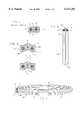
- FIG. 1is a cross section of prior art zip wire.
- FIG. 2is a cross sectional representation of two adjacent sections of insulated cable formed in accordance with the principles of the present invention.
- FIG. 3is a vertical plan view of a pancake coil of wire formed utilizing the principles taught herein.
- FIG. 4is a perspective view of a pancake coil of wire formed utilizing the principles taught herein.
- FIG. 5is a cross-sectional representation of an insulated cable constructed according to the principles of the present invention, demonstrating the cables separation into its individual inserted wires.
- FIG. 6is a cross-sectional representation of a single insulated coaxial cable constructed according to the principles of the present invention.
- insulated cable 10comprises a mass of dielectric 12 having imbedded therein a pair of conductive wires 30 and 31.
- dielectric 12is a linear polyethylene (LPE) dielectric
- wires 30 and 31utilize Monster Cable's Time Correct® wound copper wire, as taught in U.S. Pat. No. 4,538,023, and Magnetic Flux Tube® construction, as taught in U.S. Pat. No. 4,734,544.
- LPElinear polyethylene
- wires 30 and 31utilize Monster Cable's Time Correct® wound copper wire, as taught in U.S. Pat. No. 4,538,023, and Magnetic Flux Tube® construction, as taught in U.S. Pat. No. 4,734,544.
- Other wire configurations, both novel and those well known to those having ordinary skill in the artmay, with equal facility be utilized where desired.
- Dielectric 12is formed to perform the advantages taught herein in the following manner: An upper, or first surface of the cable's dielectric 12, is formed with a protrusion 14. A lower or second surface of the cable's dielectric 12 is formed with a matching depression, 15. The cross-sectional proportions of protrusion 14 enable its mating, or nesting, within depression 15 in a coiled cable configuration. According to a first preferred embodiment of the present invention, a notch or slit 16 is further provided in at least one of protrusion 14 and depression 15 to enable a workman to easily separate cable 10 into a plurality of individual insulated wires 10' and 10". In one preferred embodiment of the present invention slit 16 may be formed adjacent to depression 15.
- slit 16may, with equal facility, be formed in conjunction with protrusion 14, and may, as a further alternative, be formed in both protrusion 14 and depression 15.
- the formation of dielectric 12is preferably accomplished by extrusive means, but alternative formation methodologies including, but not necessarily limited to: casting; sintering; molding; and vacuum forming may, with equal facility be utilized.
- protrusion 14 and mating depression 15take the form of a rounded trapezoid.
- Other applicationsmay require the use of alternative geometric forms including, but not limited to square, rectangle, arcuate, circular, ovoid, triangular, conical, elliptical, parabolic, hyperbolic, other regular geometric forms and specialized shapes required by a given application.
- the present inventionspecifically contemplates all such forms and shapes.
- protrusion 14 and mating depression 15may alternatively be formed to include a barb, detent, or similar device (not shown) to more intimately retain adjacent coils of wire 10 in mated contact.
- protrusion 14 of a lower coil of cable 10is urged in the direction marked "A". This results in the protrusion mating with depression 15 of an upper, or subsequent coil of cable 10. This mating tends to reduce the slippage between adjacent coils of cable 10 thereby tending to retain cable 10 in its coiled formation when so wound.
- FIGS. 3 and 4show the formation of a pancake of cable utilizing the principles of the present invention.
- cable 10is wound flatly and concentrically into the flat helix, or pancake 20, shown in FIG. 3.
- This concentric windingforms a ridge, 21 of protrusion 14, about one surface of the pancake.
- the longitudinal notch 22 formed by depression 15is engaged with ridge 21, thereby tending to retain a second layer of cable 10 in axial alignment with a first layer thereof.
- FIG. 5the separation of one embodiment of cable 10 into its component insulated wires is shown. Having reference to that figure, a length of twisted multiple-strand wire 10 is shown being pulled as shown in the directions of the arrows marked B and B'. This pulling tends to separate dielectric 12 as shown, whereby notch or slit 16 propagates or spreads through dielectric 12 at 17. This separation results in the splitting of cable 10 into, in this first preferred embodiment, a pair of insulated wires 10' and 10". Subsequent to this splitting, wires 10' and 10" may be stripped, attached, electrically and/or mechanically connected and/or terminated in any manner well known to those having ordinary skill in the art.
- FIG. 5details the splitting of a cable 10 having a pair of conductors 30 and 31, insulated by dielectric 12 and splittable into two separate insulated wires 30 and 31.
- Similar cableshaving either a single conductor, a pair of conductors, 30 and 31 as shown, or a larger plurality of conductors, as may be required in other applications, could, with equal facility be implemented.
- the principles of the present inventionspecifically contemplate all such embodiments.
- Stackable coaxial cable 60in this embodiment, comprises a single coaxial cable 61, formed within a mass of dielectric 12 formed as before to define mating protrusion 14 and depression 15. Since this embodiment incorporates a single coaxial cable 61, slit 16, enabling the splitting of the cable, is omitted.
- cable 60may be implemented in similar fashion as previously shown cable 10 to include slit 16 (not shown in this figure), thereby enabling the splitting of cable 60 into a corresponding plurality of dielectric-packaged coaxial cables, 61.
Landscapes
- Communication Cables (AREA)
Abstract
Description
Claims (7)
Priority Applications (1)
| Application Number | Priority Date | Filing Date | Title |
|---|---|---|---|
| US09/004,167US6111202A (en) | 1998-01-02 | 1998-01-02 | Stackable electrical cable |
Applications Claiming Priority (1)
| Application Number | Priority Date | Filing Date | Title |
|---|---|---|---|
| US09/004,167US6111202A (en) | 1998-01-02 | 1998-01-02 | Stackable electrical cable |
Publications (1)
| Publication Number | Publication Date |
|---|---|
| US6111202Atrue US6111202A (en) | 2000-08-29 |
Family
ID=21709508
Family Applications (1)
| Application Number | Title | Priority Date | Filing Date |
|---|---|---|---|
| US09/004,167Expired - LifetimeUS6111202A (en) | 1998-01-02 | 1998-01-02 | Stackable electrical cable |
Country Status (1)
| Country | Link |
|---|---|
| US (1) | US6111202A (en) |
Cited By (25)
| Publication number | Priority date | Publication date | Assignee | Title |
|---|---|---|---|---|
| WO2005022560A1 (en)* | 2003-08-27 | 2005-03-10 | Dugald Morrow | Conductor members |
| US20050101192A1 (en)* | 2003-11-06 | 2005-05-12 | Kenneth Foskey | Trip resistant utility cord |
| US6909050B1 (en)* | 2003-09-26 | 2005-06-21 | Plantronics, Inc. | Electrical cable |
| US20070227759A1 (en)* | 2004-09-30 | 2007-10-04 | Carlson John R | Coupled building wire |
| US20080217044A1 (en)* | 2003-10-01 | 2008-09-11 | Southwire Company | Coupled building wire assembly |
| US20100218971A1 (en)* | 2009-02-27 | 2010-09-02 | Shenzhen Futaihong Precision Industry Co., Ltd. | Foldable electric cord and electrical connecting device using the same |
| US8002586B2 (en) | 2009-09-25 | 2011-08-23 | Pucline, Llc | Electrical power supplying device having a lower deck housing region for containing and concealing a plurality of electrical power adapters associated with a plurality of electrical appliances, and an upper deck housing region for supporting a ring-like power assembly having a central aperture and receiving the power plugs and/or power adapters of electrical appliances, while managing excess power cord length within a 3D volume passing through said central aperture |
| US8002587B2 (en) | 2009-09-25 | 2011-08-23 | Pucline, Llc | Ring-like electical power supplying structure for receiving the electrical power plugs of a plurality of electrical appliances and powering the same |
| US8016611B2 (en) | 2009-09-25 | 2011-09-13 | Pucline Llc | Electrical power supplying device having a ring-like structure for receiving the power plugs and/or power adapters associated with a plurality of electrical appliances, and an integrated thermal management system |
| US8026633B2 (en) | 2009-09-25 | 2011-09-27 | Pucline, Llc | Wall-mountable electrical power supplying device for mounting to a wall surface about a standard wall-mounted power receptacle, using a mounting bracket arranged between the housing and wall surface and an electrical power supply plug integrated with the housing |
| US20120073857A1 (en)* | 2010-09-23 | 2012-03-29 | Stephen Thomas Kelly | Cable with integrated cable-management system |
| US8159085B2 (en) | 2009-09-25 | 2012-04-17 | Pucline, Llc | Wall-mountable electrical power supplying device having a ring-like structure for receiving the power plugs and/or power adapters associated with a plurality of electrical appliances, and a housing containing and concealing the same during power supply operations |
| US8174147B2 (en) | 2009-09-25 | 2012-05-08 | Pucline, Llc | Electrical power supplying device having a ring-like power assembly for receiving electrical power plugs and/or power adapters associated with a plurality of electrical appliances, and an un-interrupted power supply (UPS) unit having a battery componenent mounted within a centrally-disposed structure passing through a central aperture in said ring-like power assembly |
| US20120126051A1 (en)* | 2010-11-23 | 2012-05-24 | Emmanuel Legrand | Cutting wire for plant-cutting equipment |
| US8193658B2 (en) | 2009-09-25 | 2012-06-05 | Pucline, Llc | Electrical power supplying device having a ring-like subassembly for receiving the power plugs and/or power adapters associated with a plurality of electrical appliances, and managing excess power cord length therewithin in a concealed manner |
| US8217528B2 (en) | 2009-09-25 | 2012-07-10 | PUCline, Inc. | Electrical power supplying device having a ring-like subassembly for receiving the power plugs and/or power adapters associated with a plurality of electrical appliances, and a housing design for containing and concealing the power plug and adaptors during power supplying operations |
| WO2013048890A3 (en)* | 2011-09-28 | 2013-06-13 | 3M Innovative Properties Company | Cell tower cable assembly and system |
| CN104969306A (en)* | 2012-12-11 | 2015-10-07 | Abb技术有限公司 | Method and device for heat treatment of power cables |
| US9184546B2 (en) | 2009-09-25 | 2015-11-10 | Pucline, Llc | Electrical power supplying device having a central power-hub assembly supplying electrical power to power plugs, adaptors and modules while concealed from view and managing excess power cord during power supplying operations |
| US9513682B2 (en) | 2013-07-03 | 2016-12-06 | Pucline, Llc | Transportable electrical power supplying device for storing and configuring excess power cord and sharing a multiplicity of AC and DC electrical power supplies in diverse user environments |
| US20170155996A1 (en)* | 2014-07-08 | 2017-06-01 | Seungho Lee | Earphone device |
| US9912154B2 (en) | 2009-09-25 | 2018-03-06 | Pucline, Llc | Electrical power supplying device having a central power-receptacle assembly with a penisula-like housing structure supplying electrical power to power plugs, adaptors and modules while concealed from view during power supplying operations |
| US9927837B2 (en) | 2013-07-03 | 2018-03-27 | Pucline, Llc | Electrical power supplying system having an electrical power supplying docking station with a multi-function module for use in diverse environments |
| US10150252B2 (en) | 2014-09-23 | 2018-12-11 | Stryker Sustainability Solutions, Inc. | Method of recoupling components during reprocessing |
| US20190097351A1 (en)* | 2017-09-23 | 2019-03-28 | Luxshare Precision Industry Co., Ltd. | Round cable |
Citations (9)
| Publication number | Priority date | Publication date | Assignee | Title |
|---|---|---|---|---|
| US2081634A (en)* | 1934-09-27 | 1937-05-25 | American Steel & Wire Co | Electric cord or cable |
| US2581472A (en)* | 1948-03-30 | 1952-01-08 | Whitney Blake Co | Multiple conductor insulated wire |
| US2969421A (en)* | 1957-07-12 | 1961-01-24 | Ite Circuit Breaker Ltd | Low x bus |
| US4058704A (en)* | 1974-12-27 | 1977-11-15 | Taeo Kim | Coilable and severable heating element |
| US4230895A (en)* | 1978-11-30 | 1980-10-28 | Hydrocarbon Research, Inc. | Thermal hydrodealkylation of alkyl phenols |
| US4369391A (en)* | 1979-06-13 | 1983-01-18 | Thomson-Csf | Pressure-sensing transducer device having a piezoelectric polymer element and a method of fabrication of said device |
| US4847443A (en)* | 1988-06-23 | 1989-07-11 | Amphenol Corporation | Round transmission line cable |
| US5113036A (en)* | 1990-04-25 | 1992-05-12 | At&T Bell Laboratories | Modular cable |
| US5811735A (en)* | 1996-11-22 | 1998-09-22 | Thomas & Betts Corporation | Fine pitch flat cable having improved connector alignment profile |
- 1998
- 1998-01-02USUS09/004,167patent/US6111202A/ennot_activeExpired - Lifetime
Patent Citations (9)
| Publication number | Priority date | Publication date | Assignee | Title |
|---|---|---|---|---|
| US2081634A (en)* | 1934-09-27 | 1937-05-25 | American Steel & Wire Co | Electric cord or cable |
| US2581472A (en)* | 1948-03-30 | 1952-01-08 | Whitney Blake Co | Multiple conductor insulated wire |
| US2969421A (en)* | 1957-07-12 | 1961-01-24 | Ite Circuit Breaker Ltd | Low x bus |
| US4058704A (en)* | 1974-12-27 | 1977-11-15 | Taeo Kim | Coilable and severable heating element |
| US4230895A (en)* | 1978-11-30 | 1980-10-28 | Hydrocarbon Research, Inc. | Thermal hydrodealkylation of alkyl phenols |
| US4369391A (en)* | 1979-06-13 | 1983-01-18 | Thomson-Csf | Pressure-sensing transducer device having a piezoelectric polymer element and a method of fabrication of said device |
| US4847443A (en)* | 1988-06-23 | 1989-07-11 | Amphenol Corporation | Round transmission line cable |
| US5113036A (en)* | 1990-04-25 | 1992-05-12 | At&T Bell Laboratories | Modular cable |
| US5811735A (en)* | 1996-11-22 | 1998-09-22 | Thomas & Betts Corporation | Fine pitch flat cable having improved connector alignment profile |
Cited By (34)
| Publication number | Priority date | Publication date | Assignee | Title |
|---|---|---|---|---|
| WO2005022560A1 (en)* | 2003-08-27 | 2005-03-10 | Dugald Morrow | Conductor members |
| US6909050B1 (en)* | 2003-09-26 | 2005-06-21 | Plantronics, Inc. | Electrical cable |
| US20080217044A1 (en)* | 2003-10-01 | 2008-09-11 | Southwire Company | Coupled building wire assembly |
| US20050101192A1 (en)* | 2003-11-06 | 2005-05-12 | Kenneth Foskey | Trip resistant utility cord |
| US20070227759A1 (en)* | 2004-09-30 | 2007-10-04 | Carlson John R | Coupled building wire |
| US8198537B2 (en)* | 2009-02-27 | 2012-06-12 | Shenzhen Futaihong Precision Industry Co., Ltd. | Foldable electric cord and electrical connecting device using the same |
| US20100218971A1 (en)* | 2009-02-27 | 2010-09-02 | Shenzhen Futaihong Precision Industry Co., Ltd. | Foldable electric cord and electrical connecting device using the same |
| US8217528B2 (en) | 2009-09-25 | 2012-07-10 | PUCline, Inc. | Electrical power supplying device having a ring-like subassembly for receiving the power plugs and/or power adapters associated with a plurality of electrical appliances, and a housing design for containing and concealing the power plug and adaptors during power supplying operations |
| US8193658B2 (en) | 2009-09-25 | 2012-06-05 | Pucline, Llc | Electrical power supplying device having a ring-like subassembly for receiving the power plugs and/or power adapters associated with a plurality of electrical appliances, and managing excess power cord length therewithin in a concealed manner |
| US8026633B2 (en) | 2009-09-25 | 2011-09-27 | Pucline, Llc | Wall-mountable electrical power supplying device for mounting to a wall surface about a standard wall-mounted power receptacle, using a mounting bracket arranged between the housing and wall surface and an electrical power supply plug integrated with the housing |
| US9184546B2 (en) | 2009-09-25 | 2015-11-10 | Pucline, Llc | Electrical power supplying device having a central power-hub assembly supplying electrical power to power plugs, adaptors and modules while concealed from view and managing excess power cord during power supplying operations |
| US8159085B2 (en) | 2009-09-25 | 2012-04-17 | Pucline, Llc | Wall-mountable electrical power supplying device having a ring-like structure for receiving the power plugs and/or power adapters associated with a plurality of electrical appliances, and a housing containing and concealing the same during power supply operations |
| US8174147B2 (en) | 2009-09-25 | 2012-05-08 | Pucline, Llc | Electrical power supplying device having a ring-like power assembly for receiving electrical power plugs and/or power adapters associated with a plurality of electrical appliances, and an un-interrupted power supply (UPS) unit having a battery componenent mounted within a centrally-disposed structure passing through a central aperture in said ring-like power assembly |
| US8016611B2 (en) | 2009-09-25 | 2011-09-13 | Pucline Llc | Electrical power supplying device having a ring-like structure for receiving the power plugs and/or power adapters associated with a plurality of electrical appliances, and an integrated thermal management system |
| US9912154B2 (en) | 2009-09-25 | 2018-03-06 | Pucline, Llc | Electrical power supplying device having a central power-receptacle assembly with a penisula-like housing structure supplying electrical power to power plugs, adaptors and modules while concealed from view during power supplying operations |
| US8002587B2 (en) | 2009-09-25 | 2011-08-23 | Pucline, Llc | Ring-like electical power supplying structure for receiving the electrical power plugs of a plurality of electrical appliances and powering the same |
| US8002586B2 (en) | 2009-09-25 | 2011-08-23 | Pucline, Llc | Electrical power supplying device having a lower deck housing region for containing and concealing a plurality of electrical power adapters associated with a plurality of electrical appliances, and an upper deck housing region for supporting a ring-like power assembly having a central aperture and receiving the power plugs and/or power adapters of electrical appliances, while managing excess power cord length within a 3D volume passing through said central aperture |
| US8697997B2 (en)* | 2010-09-23 | 2014-04-15 | Cisco Systems, Inc. | Cable with integrated cable-management system |
| US20120073857A1 (en)* | 2010-09-23 | 2012-03-29 | Stephen Thomas Kelly | Cable with integrated cable-management system |
| US20120126051A1 (en)* | 2010-11-23 | 2012-05-24 | Emmanuel Legrand | Cutting wire for plant-cutting equipment |
| WO2013048890A3 (en)* | 2011-09-28 | 2013-06-13 | 3M Innovative Properties Company | Cell tower cable assembly and system |
| CN103842874A (en)* | 2011-09-28 | 2014-06-04 | 3M创新有限公司 | Cell tower cable assembly and system |
| CN104969306A (en)* | 2012-12-11 | 2015-10-07 | Abb技术有限公司 | Method and device for heat treatment of power cables |
| CN104969306B (en)* | 2012-12-11 | 2016-10-19 | Abb瑞士股份有限公司 | Method and device for heat treatment of power cables |
| US9799430B2 (en)* | 2012-12-11 | 2017-10-24 | Abb Hv Cables (Switzerland) Gmbh | Method for heat treatment of an electric power cable |
| US20150332815A1 (en)* | 2012-12-11 | 2015-11-19 | Abb Technology Ltd | A method and an apparatus for heat treatment of an electric power cable |
| US9513682B2 (en) | 2013-07-03 | 2016-12-06 | Pucline, Llc | Transportable electrical power supplying device for storing and configuring excess power cord and sharing a multiplicity of AC and DC electrical power supplies in diverse user environments |
| US9927837B2 (en) | 2013-07-03 | 2018-03-27 | Pucline, Llc | Electrical power supplying system having an electrical power supplying docking station with a multi-function module for use in diverse environments |
| US11150697B2 (en) | 2013-07-03 | 2021-10-19 | Pucline Llc | Multi-function electrical power supplying station with dockable station supporting emergency lighting, portable lighting, and consumer device battery recharging modes of operation |
| US11614784B2 (en) | 2013-07-03 | 2023-03-28 | Pucline, Llc | Electrical power supplying and cord management station with dockable module supporting multiple modes of operation |
| US20170155996A1 (en)* | 2014-07-08 | 2017-06-01 | Seungho Lee | Earphone device |
| US10150252B2 (en) | 2014-09-23 | 2018-12-11 | Stryker Sustainability Solutions, Inc. | Method of recoupling components during reprocessing |
| US20190097351A1 (en)* | 2017-09-23 | 2019-03-28 | Luxshare Precision Industry Co., Ltd. | Round cable |
| US10424868B2 (en)* | 2017-09-23 | 2019-09-24 | Luxshare Precision Industry Co., Ltd. | Round cable |
Similar Documents
| Publication | Publication Date | Title |
|---|---|---|
| US6111202A (en) | Stackable electrical cable | |
| US4719319A (en) | Spiral configuration ribbon coaxial cable | |
| US8563860B1 (en) | Large loop retractile cord | |
| US4820014A (en) | Optical cable | |
| US9088192B2 (en) | Conductor wire for motor and coil for motor | |
| JP2016103398A (en) | Shield cable | |
| JPH06101250B2 (en) | Cable with corrugated partition | |
| US4910360A (en) | Cable assembly having an internal dielectric core surrounded by a conductor | |
| JPH06168631A (en) | Litz wire for high frequency transformer and double braided litz wire and manufacture thereof | |
| US3445797A (en) | Inductor coil and bobbin with terminals | |
| JP3058203B2 (en) | Optical cable | |
| US4734544A (en) | Signal cable having an internal dielectric core | |
| US5929374A (en) | Electric cable and connector system | |
| US20060027392A1 (en) | Audio signal cable | |
| US6059080A (en) | Wire wheel with continuous electrical connection | |
| CN109887723B (en) | Balun transformer and method of manufacturing the same | |
| JP2002093633A (en) | Transformer | |
| EP3813081B1 (en) | Communication cable and wire harness | |
| US20090236119A1 (en) | Finned jacket with core wrap for use in lan cables | |
| CN115023772A (en) | Communication cable and method for manufacturing the same | |
| US20020079128A1 (en) | Cable with dual filament insulator and process for selecting the effective dielectric constant of an insulated cable | |
| JP5354918B2 (en) | Electric wire, litz wire and winding | |
| JPH09115756A (en) | Coil component and its manufacturing method | |
| JP3701247B2 (en) | Video transmission cable | |
| US3936931A (en) | Method employing a lead holder to retain a lead connection on an electrical coil |
Legal Events
| Date | Code | Title | Description |
|---|---|---|---|
| AS | Assignment | Owner name:MONSTER CABLE PRODUCTS, INC., CALIFORNIA Free format text:ASSIGNMENT OF ASSIGNORS INTEREST;ASSIGNOR:MARTIN, DEMIAN T.;REEL/FRAME:009200/0593 Effective date:19980318 | |
| STCF | Information on status: patent grant | Free format text:PATENTED CASE | |
| AS | Assignment | Owner name:IMPERIAL BANK, AS AGENT, CALIFORNIA Free format text:SECURITY AGREEMENT;ASSIGNORS:MONSTER CABLE PRODUCTS, INC.;LEE, NOEL;REEL/FRAME:011667/0124 Effective date:20010208 | |
| FEPP | Fee payment procedure | Free format text:PAT HOLDER NO LONGER CLAIMS SMALL ENTITY STATUS, ENTITY STATUS SET TO UNDISCOUNTED (ORIGINAL EVENT CODE: STOL); ENTITY STATUS OF PATENT OWNER: LARGE ENTITY | |
| REFU | Refund | Free format text:REFUND - SURCHARGE, PETITION TO ACCEPT PYMT AFTER EXP, UNINTENTIONAL (ORIGINAL EVENT CODE: R2551); ENTITY STATUS OF PATENT OWNER: LARGE ENTITY | |
| FPAY | Fee payment | Year of fee payment:4 | |
| FPAY | Fee payment | Year of fee payment:8 | |
| FPAY | Fee payment | Year of fee payment:12 |