US6110167A - Contact tip for laser surgery - Google Patents
Contact tip for laser surgeryDownload PDFInfo
- Publication number
- US6110167A US6110167AUS08/455,061US45506195AUS6110167AUS 6110167 AUS6110167 AUS 6110167AUS 45506195 AUS45506195 AUS 45506195AUS 6110167 AUS6110167 AUS 6110167A
- Authority
- US
- United States
- Prior art keywords
- tip
- shield
- contact tip
- contact
- laser
- Prior art date
- Legal status (The legal status is an assumption and is not a legal conclusion. Google has not performed a legal analysis and makes no representation as to the accuracy of the status listed.)
- Expired - Fee Related
Links
Images


Classifications
- A—HUMAN NECESSITIES
- A61—MEDICAL OR VETERINARY SCIENCE; HYGIENE
- A61B—DIAGNOSIS; SURGERY; IDENTIFICATION
- A61B18/00—Surgical instruments, devices or methods for transferring non-mechanical forms of energy to or from the body
- A61B18/18—Surgical instruments, devices or methods for transferring non-mechanical forms of energy to or from the body by applying electromagnetic radiation, e.g. microwaves
- A61B18/20—Surgical instruments, devices or methods for transferring non-mechanical forms of energy to or from the body by applying electromagnetic radiation, e.g. microwaves using laser
- A61B18/22—Surgical instruments, devices or methods for transferring non-mechanical forms of energy to or from the body by applying electromagnetic radiation, e.g. microwaves using laser the beam being directed along or through a flexible conduit, e.g. an optical fibre; Couplings or hand-pieces therefor
- G—PHYSICS
- G02—OPTICS
- G02B—OPTICAL ELEMENTS, SYSTEMS OR APPARATUS
- G02B6/00—Light guides; Structural details of arrangements comprising light guides and other optical elements, e.g. couplings
- G02B6/24—Coupling light guides
- G02B6/241—Light guide terminations
- A—HUMAN NECESSITIES
- A61—MEDICAL OR VETERINARY SCIENCE; HYGIENE
- A61B—DIAGNOSIS; SURGERY; IDENTIFICATION
- A61B18/00—Surgical instruments, devices or methods for transferring non-mechanical forms of energy to or from the body
- A61B18/18—Surgical instruments, devices or methods for transferring non-mechanical forms of energy to or from the body by applying electromagnetic radiation, e.g. microwaves
- A61B18/20—Surgical instruments, devices or methods for transferring non-mechanical forms of energy to or from the body by applying electromagnetic radiation, e.g. microwaves using laser
- A61B18/22—Surgical instruments, devices or methods for transferring non-mechanical forms of energy to or from the body by applying electromagnetic radiation, e.g. microwaves using laser the beam being directed along or through a flexible conduit, e.g. an optical fibre; Couplings or hand-pieces therefor
- A61B2018/2255—Optical elements at the distal end of probe tips
- A61B2018/2272—Optical elements at the distal end of probe tips with reflective or refractive surfaces for deflecting the beam
Definitions
- the present inventionrelates generally to laser surgery probes, and particularly to probes having contact tips which are heated by laser energy.
- Contact tipsare commonly used in laser surgery for a variety of procedures, including surgical incisions and coagulation.
- such contact tipscomprise a tip body of a transparent material such as sapphire which is capable of withstanding high temperatures.
- the sapphiremay be coated with a coating that is absorptive to laser energy. Absorption of the laser energy heats the tip to high temperatures suitable for tissue vaporization.
- One problem with such tipsis that they do not distribute the laser energy evenly and thus heating is not uniform. Further, due to toxicity or other adverse effects of the coating, an overcoat of, for example, ceramic or glass, must be applied to prevent the coating from contacting the tissue. Examples of contact tips utilizing absorptive coatings are disclosed in U.S. Pat. Nos. 4,736,743 and 4,832,979.
- contact tipsreceive laser energy from a waveguide, such as an optical fiber.
- Laser lightpropagates out of the waveguide end through an air gap and strikes an input face of the contact tip.
- the input faceis generally normal to the axis of propagation. Because the indices of refraction between the waveguide, the air gap and the contact tip material do not match, some radiation is reflected from the input face, resulting in build up of thermal energy.
- contact tips configurationsare conical, hemispherical, flat or chisel-shaped, and a complete set of tips can be expensive. Moreover, the inconvenience of changing a tip and the time involved in doing so is a disadvantage to tactile laser surgery.
- the laser surgery apparatus of the present inventioncomprises a contact tip having a tip body.
- An input face of the tip bodyreceives laser energy from an optical waveguide.
- the tip bodyis coated with a coating that is reflective to the laser energy. Such reflectivity causes the laser energy to be distributed substantially evenly throughout the tip to provide generally uniform heating.
- the tip bodycomprises a substantially transparent material
- the coatingforms a reflective cavity around the substantially transparent material.
- the coatingconsists essentially of a single coating material, such as tantalum, which is biologically compatible, and the transparent material comprises a crystalline material such as Al 2 O 3 (i.e., sapphire).
- the laser surgery apparatuscomprises a contact tip which receives laser energy.
- the tipcomprises a tip body coated with a coating consisting essentially of a material which is biologically compatible with tissue to prevent generation of a toxic tissue response. Due to the biological compatibility, overcoating the coating material is unnecessary.
- the coating materialcomprises an elemental metal, such as tantalum, and the tip body comprises Al 2 O 3 (i.e., sapphire). Such coating forms a surface which is reflective for wavelengths over the entire optical spectrum.
- the laser surgery apparatuscomprises a contact tip including an input face having a surface for receiving laser light propagating along an axis of propagation defined by an optical waveguide.
- the surface of the input faceis inclined relative to the axis of propagation such that an angle of incidence between the laser light and the surface is approximately equal to Brewster's angle.
- the surfaceis a smooth, conical shape extending into the body of the contact tip, which comprises Al 2 O 3 (i.e., sapphire). Longitudinally, the surface is generally linear. As a result of the conical shape, the initially reflected light will strike the surface multiple times until the bulk of the remaining energy is transmitted to the contact tip.
- the laser surgery apparatuscomprises a contact tip which receives laser light.
- the tipcomprises a tip body having a generally conical exterior with a substantially flat surface disposed obliquely to a cone axis of the tip body.
- the tip bodyfurther comprises an obliquely truncated tip and a second substantially flat surface disposed obliquely to the first flat surface. The first and second flat surfaces intersect proximal to the truncated tip to form an edge extending from the truncated tip across the truncated surface.
- the laser surgery apparatuscomprises a contact tip which receives laser light and a shield.
- the tipabsorbs at least a portion of the laser energy, thus heating the tip.
- the shieldbeing thermally shielded from hot tip, protects the tissue adjacent to the shield from undesired thermal damage by preventing the transfer of thermal energy through the shield.
- the contact tipmay have an offset conical shape.
- the contact tipmay have a generally wedge shape or a generally hemispherical shape.
- the shieldextends circumferentially around the contact tip through at least 30° of circumference and extends longitudinally along a major portion of the contact tip.
- the shieldhas a generally semi-circular shape in the axial direction and extends longitudinally beyond the contact tip end.
- the surgery apparatusincludes at least one and preferably a plurality of cooling gas channels disposed around the contact tip base directing a flow of gas between the shield and the hot tip to thermally shield the shield for the hot contact tip.
- FIG. 1is a schematic illustration of the laser surgery apparatus of the present invention showing the laser, the optical fiber, the catheter and the laser probe;
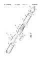
- FIG. 2is a perspective view of the laser probe according to one preferred embodiment of the present invention.
- FIG. 3is an exploded perspective view of the laser probe of FIG. 2;
- FIG. 4is a cross-sectional view of the laser probe of FIG. 2 taken along line 4--4;
- FIG. 5is a cross-sectional view of the laser probe of FIG. 4 taken along line 5--5;
- FIG. 6is a schematic illustration showing laser light propagation, transmission and reflection in relation to the laser probe contact tip of FIG. 4;
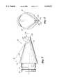
- FIG. 7is a side plan view of the laser probe contact tip of FIG. 4;
- FIG. 8is a perspective frontal view of the laser probe contact tip of FIG. 7;
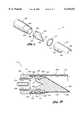
- FIG. 9is an exploded perspective view of another preferred embodiment of a laser probe including a shield
- FIG. 10is a cross-sectional assembly view of the laser probe of FIG. 9;
- FIG. 11is a perspective view showing a hemispherical contact tip
- FIG. 12is a perspective view showing a wedge-shaped contact tip.
- the laser surgery apparatus 10 of the present inventioncomprises a laser 12 which supplies laser energy to a laser probe 14.
- Light from the laser 12is coupled to a waveguide, such as an optical fiber 16, that guides the laser energy to the probe 14.
- the optical fiber 16is surrounded by a catheter 18 which extends from the laser 12 to the probe 14.
- the catheter 18may, for example, be connected to a source of cooling fluid, such as gas, in a conventional manner. Such cooling fluid is conducted along the catheter 18 from the laser 12 to the probe 14 in order to cool the fiber 16 and the probe 14.
- the distal end of probe 14comprises a tip mount 22 comprising a tubular metal sleeve which mounts a contact tip 20.
- proximal and distalare used in reference to proximity to the laser 12 which supplies the light to the fiber 16.
- the contact tip 20 in FIG. 2is shown as being generally conically tapered with a truncated tip, it will be understood that other tip configurations, such as hemispherical, flat, chisel-shaped, etc., may be used alternatively.
- the contact tip 20includes a body portion 24 having a proximal end 26 and a distal end 28.
- the proximal end 26is mounted in a distal end 30 of the tubular tip mount 22 by forming a crimp 32 in the tip mount distal end 30.
- the proximal end 26 of the contact tip body 24includes a circumferential groove 34 which receives the axially compressed material of the crimp 32.
- the tip body 24is comprised of a material which can withstand temperatures on the order of 500° C. or more, and a preferred material is crystalline Al 2 O 3 (i.e., sapphire).
- Diametrically opposed exit ports 40are provided in the tip mount sleeve 22 adjacent to the tip input face 38 to permit the cooling fluid flowing through the catheter 18 (FIG. 1) to escape.
- the proximal end of probe 14comprises a fiber holder sleeve 44, the proximal end 36 of the tip mount sleeve 22, a fiber holder 64 (FIGS. 3 and 5) and a distal end 46 of the catheter 18 (FIGS. 2 and 3); each component preferably comprises a durable, heat-resistant and corrosion-resistant material.
- a brass alloy, half-hard,is contemplated for use in the structural components 44, 22, 64, and 18, in combination with an outer protective plating comprising gold 15 millionths of an inch thick followed by a nickel strike 5 millionths of an inch thick.
- the fiber holder sleeve 44comprises a proximal sleeve portion 48, a central sleeve portion 50, and distal sleeve portion 54, as shown in FIG. 4.
- the fiber holder sleeve 44is cylindrical and has an axial bore 54 (FIGS. 3 and 5) of uniform diameter throughout its length.
- the distal portion 52 of the fiber sleeve 44has a reduced wall thickness relative to the central portion 50 so as to provide a reduced outside diameter. Threads 56 are disposed on the exterior surface of distal portion 52.
- the tip mount sleeve 22has a uniform diameter bore 58 (FIGS. 3 and 5) throughout its length. As shown in FIG. 4, the proximal end portion 36 of the tip mount sleeve 22 is tapped with female threads 60 for mating with the male threads 56 on the distal sleeve portion 52 of the fiber holder sleeve 44.
- the tip mount sleeve 22is secured to the fiber holder sleeve 44 by screwing the male threads 56 of the fiber holder sleeve 44 into the female threads 60 until the proximal end portion 36 of the tip mount sleeve 22 abuts a shoulder 62 on the central portion 50 of the fiber holder sleeve 44.
- a water-tight seal between the tip mount sleeve 22 and fiber holder sleeve 44can be provided by the use of an appropriate washer, gasket or sealant compound, as known in the art.
- the outside diameters of the tip mount sleeve 22 and the central sleeve portion 50 of the fiber holder sleeve 44are identical at their interface so as to avoid exterior surface irregularities in the laser probe 14.
- the fiber holder 64comprises an elongate member 66 having a T-shaped cross section and an elongate member 68 having a U-shaped cross section.
- the member 66has a channel 70 with a width approximately equal to that of the optical fiber 16.
- the members 66, 68are configured such that a central leg 72 of the T-shaped top member 66 fits snugly into the channel 70 formed in the U-shaped bottom member 68.
- the length of the central leg 72is less than the depth of the channel 70 by an amount equal to the diameter of the optical fiber 16, so as to provide an elongate opening in which the optical fiber 16 is disposed.
- the optical fiber 16is retained between the members 66, 68 by an interference fit or, alternatively, by chemical adhesive.
- the width of the fiber holder 64is significantly less than the diameter of the bore 54 to provide side channels 82, 84 for the passage of fluid around the fiber holder 64.
- the fiber holder 64retains the fiber 16 in an axial orientation such that the fiber axis is aligned with the central axis of the sleeves 44, 22.
- the distal end 78 of the fiber 16protrudes only a very small amount past the fiber holder to prevent sagging or bending of the end 78.
- the orientation of the fiber holder 64 within the fiber holder sleeve 44is such that the optical fiber 16 placed therein is centered and axially aligned with the contact tip 20.
- the fiber 16is held stationary within the fiber holder sleeve 44 so that the distance between the contact tip 20 and the distal end 78 of the fiber 16 remains constant. However, the relative position of the fiber end 78 and contact tip 20 can be adjusted by repositioning the fiber holder 64 within the fiber holder sleeve 44.
- the optical fiber 16is a multi-mode fiber comprising a core of relatively high refractive index which is surrounded by a cladding of relatively low refractive index.
- the corecan be made of pure silica which has been fused, and the cladding which surrounds the core may comprise fused silica which has been doped to lower the refractive index.
- the core materialis preferably significantly free of metallic impurities, resulting in less attenuation of the transmitted laser energy as it travels through the fiber 16.
- Specific purpose fiberswhich are readily available and known in the art, may be desirable for certain wavelengths which are difficult to transmit through optical fibers. For example, UV grade fibers may be appropriate for very short wavelengths and zirconium fluoride fibers have been found to be advantageous for long wavelengths. Further, hollow core waveguides have found application in some cases.
- the length of the fiber 16is typically about 50 to 500 cm, and preferably about 200 to 400 cm.
- the corehas a diameter 106 (FIG. 6) of approximately 600 microns. Fiber core diameters for medical applications are typically in the range from 200 to 600 microns.
- the optical fiber 16is surrounded by a protective catheter sleeve 18 comprised of materials, such as PVC, cured epoxy or Teflon.
- the catheter sleeve 18has an outside diameter which is equal to that of the central portion 50 of the fiber holder sleeve 44. In the preferred embodiment, the catheter diameter is 2.2 mm. In general, the diameter of the catheter sleeve 18 will typically be no more than 4.0 mm.
- the proximal portion 48 of the fiber holder sleeve 44has an outside diameter which is reduced relative to the central portion 50 by twice the thickness of the catheter sleeve 18 to allow the catheter sleeve 18 to snugly fit over the portion 48, with the distal end of the catheter sleeve 46 abutting a shoulder 80 (FIG. 2) on the central portion 56 of the fiber holder sleeve 44.
- the catheter sleeve 18is affixed to the portion 48 by chemical adhesive to insure a water-tight connection.
- the portion of the tip body 24 that extends from the tip mount sleeve 22is coated with a coating 42.
- the coatingcomprises a broadband reflective material, such as a metal, which is reflective for wavelengths over the entire optical spectrum. While a variety of coating materials may be utilized, and the coating may include an undercoat or overcoat, the coating of the preferred embodiment comprises a single coating material having a substantially uniform composition.
- the coating materialis selected to provide good adherence to the tip body 24 so as to prevent flaking or other deleterious effects.
- the coating material (and oxides thereof)is preferably a biologically compatible material that will not generate a toxic tissue response or other biological incompatibility when used in a laser surgery environment.
- Examples of biologically compatible materials which can be applied directly to Al 2 O 3 (without undercoat)include tantalum, tungsten, titanium, and vanadium. Although all of these coating materials have good adherence properties for a tip body comprised of Al 2 O 3 and exhibit good biological compatibility without the need for an overcoat, tantalum is presently considered to be the preferred material, due to its excellent adherence properties and biological compatibility. Gold may also be a suitable material for some applications, however, it has been found that gold does not adhere as well to Al 2 O 3 as the above-mentioned materials unless an undercoat, e.g., of nickel, is utilized.
- a sapphire blankPrior to coating, a sapphire blank is machined to produce the desired tip configuration. The resulting exterior surface finish is smooth but unpolished (i.e., not optical quality).
- a metallization sourceis used to deposit a metal coating 42 over the portion of the contact tip 20 which extends from the tip mount sleeve 22.
- the metal coating 42is evaporated onto the structure using conventional metal evaporation processes.
- the resulting coating 42is a thin metal film over a portion of the exterior of the contact tip body 24. Although the coating 42 is hard, the coating 42 does not structurally support itself. Instead, the structure of the tip body portion 24 maintains the shape of the contact tip 20.
- the coated portion of the contact tip 20is applied directly to tissue to form, e.g., a surgical incision or to coagulate the tissue.
- the reflective coating 42forms a reflective cavity for the laser energy, and multiple reflections within this cavity distribute the laser energy substantially evenly throughout the cavity, thereby providing substantially uniform heating of the coating 42 along the entire length of the tip. Such reflection also serves to prevent significant amounts of laser energy from escaping the tip, and thus permits the tip 20 to be heated to high temperatures with relatively low input energy.
- the coating 42is biologically compatible, it can be applied directly to the tissue without a protective overcoat.
- Contact tips coated in this mannercan be used with a variety of laser sources, including Erbium YAG, Neodymium YAG, Argon and CO 2 .
- these coated tipsadd a thermal characteristic to laser sources which previously lacked cauterizing ability, i.e., Erbium YAG, Neodymium YAG and Argon lasers.
- the input face 38has a smooth generally conical surface 100 which extends form the periphery of the input face 38, into the contact tip body 24 and to a vertex 102. Longitudinally, the surface 100 is linear.
- the conical surface 100defines a recess in the contact tip body having a diameter 104 at the input face 38 that is substantially equal to or greater than the optical fiber core diameter 106.
- the surface 100is inclined from a line 108 bisecting the vertex 102 such that an angle ⁇ , formed between the surface 100 and a line 110 perpendicular to the bisecting line 108, is substantially equal to Brewster's angle.
- Brewster's angleis equal to tan -1 n 2 /n 1 , where n 1 equals the refractive index of the cooling fluid (gas in the preferred embodiment) and n 2 equals the refractive index of the contact tip body material, as shown in FIG. 6.
- the bisecting line 108is substantially parallel to an axis of propagation 112 and preferably coincides with the axis of propagation 112.
- an angle of incidence ⁇ between the laser light 114 and the conical surface 100is approximately equal to Brewster's angle.
- essentially all of the parallel polarized laser light 116is transmitted to the contact tip body 24 and the perpendicular polarized laser light 118 is reflected.
- the initially reflected light 118strikes an opposing side of the conical surface 100 at a decreased angle of incidence, and thereby transmits a substantial portion of the reflected light into the tip body 24.
- the remaining incident laser lightwill undergo multiple reflections along the conical surface 100 until substantially all of laser light is transmitted to the contact tip body 24.
- the conical shape and of the initial angle of incidencebeing equal to Brewster's angle, less radiation is reflected, thereby reducing the amount of thermal energy build up.
- the distal end 78 of the optical fiber 16is disposed proximal to the conical surface 100 with a small gap 119 formed between the components 78, 100.
- the laser light 114may diverge somewhat while propagating through the gap 119 filled with cooling fluid, essentially all of the light will strike the conical surface 100 at an angle of incidence a approximately equal to Brewster's angle because of the narrowness of the gap 119.
- the contact tip 20preferably includes a generally conical portion 120 having a truncated tip portion 122 defining an apex 132.
- the truncated tip portion 120also includes a pair of substantially flat surfaces 124, 126 disposed obliquely to a cone axis 128 of the conical portion 120 and proximal to the apex 132.
- the flat surfaces 124, 126intersect each other and form an edge 130 extending from the apex 132.
- This contact tip configurationis accomplished by truncating a tip of a cone at an angle ⁇ with respect to the base of the cone, as shown in FIG. 7.
- two substantially flat, intersecting surfaces 124, 126are cut on the cone to form a cutting edge 130 along a line starting from the apex 132 of the truncated tip 122 and extending along a line of symmetry of the truncated surface.
- the coating 42may be alternatively applied only to selected portions of the tip 20.
- the coating 42may be applied only to the conical portion 120 and may be omitted from the surfaces 124, 126 of the truncated tip portion 122 such that light is transmitted from the tip 20 through the surfaces 124, 126 to irradiate the tissue.
- the contact tip 20When used in surgical operations, the contact tip 20 offers the surgeon a variety of working surfaces enabling various types of incisions and degrees of coagulation with one contact tip. Cutting similar to a conventional conical tip is achieved by placing the apex 132 of the truncated tip 122 in contact with the tissue. Scalpel like cutting comparable to that achieved with a conventional chisel tip is accomplished by drawing the sharp edge 130 across the tissue. Tissue coagulation is achieved by placing the large curved surface 134 or the flat surfaces 124, 126 in contact with the tissue. The curved surface 134 and the flat surfaces 124, 126 simulate conventional hemispherical and flat shaped contact tips, respectively.
- contact tip 20acan have a generally conical exterior with a substantially flat surface disposed obliquely to the axis of the conical tip.
- the contact tip 20acan further have a second flat surface intersecting the first flat surface to produce a sharp edge.
- these flat surfacescan be positioned with respect to an apex of the tip such that the edge extends from the apex, as is the case in the preferred embodiment.
- the probe assembly 14aincludes a shield 140 which is thermally shielded from the hot contact tip 20a.
- a shield 140protects the tissue adjacent to the shield from undesired thermal damage by preventing the transfer of thermal energy through the shield 140.
- the distal end of the probe 14acomprises a tip mount sleeve 22a, a contact tip 20a, a thermal insulation pad 142, and a shield 148.
- the proximal end of the probe 14ais identical to that previously describe above.
- the contact tip in FIG. 9is shown as being generally conical, it will be understood that other tip configurations, such as hemispherical, flat, chisel-shaped, etc., may be used alternatively.
- the contact tip 20aincludes a body portion 24a having a proximal end 26a and a distal end 28a.
- the proximal end 26ais mounted in a distal end 30a of the tubular tip mount 22a by forming a crimp 32a in the tip mount distal end 30a.
- the proximal end 26a of the contact tip 20aincludes a circumferential groove 34a which receives the axially compressed material of the crimp 32a.
- the tip body 24ais comprised of a material which can withstand temperatures on the order of 500° C. or more, and a preferred material is crystalline Al 2 O 3 (i.e., sapphire).
- the distal portion 30a of the tip mount sleeve 22ahas a reduced wall thickness so as to provide a reduced outer diameter.
- the tip mount sleeve 22afurther includes a pair of diametrically opposed exit ports 40a adjacent to the input face 38a to permit the cooling fluid flowing through the catheter 18 (FIG. 1) to escape.
- the preferred embodimentemploys two exit ports, it will be understood that there must be at least one exit port 40a and can be a plurality of exit ports spaced axially about the circumference of the tip mount sleeve 22a.
- the thermal insulation pad 142has a generally circular shape with an inner diameter 143 sized larger than the outer diameter of the distal end portion 30a.
- the thermal insulation padcomprises thermal insulation material, as known in the art, and is thick enough to provide thermal shielding of the shield 140 from the contact tip 20a. In other words, a large percentage of the heat collected in the contact tip 20a is not transmitted to the shield 140 because of the thermal insulation pad 142.
- the configuration of the contact tip 20a used with the shield 140is diametrically asymmetric with respect to the axial center-line of the probe 14a such that at least one radius, of a cross section taken along the distal end 28a of the contact tip 20a, is of greater length than its opposing radius (i.e., the radius in the 180° direction).
- diametrically asymmetric shapesare an offset conical (as shown in FIGS. 9 and 10) and a wedge shape (as shown in FIG. 12).
- the diametrically asymmetric shaped contact tip 20ais preferably disposed such that a portion of the contact tip 20a is opposite a portion of the shield 140 and extends longitudinally in a direction generally parallel to a portion of the shield 140.
- the functional surfaces of the contact tip 20ae.g., the apex and rounded surfaces of the offset conical
- the opposite, non-functional surfaces of the contact tip 20aare shielded from the tissue by shield 140.
- the shield 140comprises a proximal portion 144 having an inner diameter 146 and a distal portion 148.
- the inner diameter 146 of the shield proximal portion 144is larger than the outer diameter of the thermal insulation pad 142.
- the distal portion 148extends circumferentially around the contact tip 20a through at least 30° of circumference and preferably through 180° of circumference (i.e., the distal portion 148 has a semi-circular cross-sectional shape).
- the contact tip 20apreferably has a generally offset conical tip and the shield 148 preferably extends longitudinally along a major portion of the contact tip 20a. In other words, the shield distal end portion 148 terminates near the contact tip distal end 28a.
- the distal portion 148can extend slightly beyond the distal end 28a of the contact tip 20a, especially when used with a contact tip having a hemispherical or wedge-shape configuration, as shown in FIGS. 11 and 12, respectively.
- the thermal insulation pad 142slides over the tip mount sleeve distal end 30a to a position abutting shoulder 154.
- the shield 140is coupled to the tip mount sleeve 22a by inserting the tip mount sleeve distal end 30a into the shield proximal end 144 to a position where the shoulder 154 abuts the proximal end 144 of the shield 140.
- the outside diameters of the tip mount sleeve 22a and the shield 140are identical at their interface so as to avoid exterior surface irregularities in the laser probe 14a.
- the shield 140is secured to the tip mount sleeve 22a by spot welding the two components together, as known in the art.
- the spot welds(not shown) are positioned along the circumference of the shield proximal end 144 on the proximal side of the exit ports 40a. Assembled in this manner, channels 150, 152 are formed between the tip mount sleeve distal end 30a and the shield proximal end 144 and direct the flow of cooling fluid exiting ports 40a over the shield 140 and the contact tip 20a.
- the flow of gas through and out of the channel 150thermally shields the shield 140 from the heat radiating off of the hot contact tip 140. In other words, a large percentage of the heat radiating off the contact tip 20a is transmitted to the cooling fluid by convection and is dissipated by the cooling fluid flow. As a result, the shield 140 maintains a temperature much cooler than the temperature of the contact tip 20a.
Landscapes
- Physics & Mathematics (AREA)
- Health & Medical Sciences (AREA)
- Surgery (AREA)
- Optics & Photonics (AREA)
- Life Sciences & Earth Sciences (AREA)
- Engineering & Computer Science (AREA)
- Molecular Biology (AREA)
- Nuclear Medicine, Radiotherapy & Molecular Imaging (AREA)
- Electromagnetism (AREA)
- Biomedical Technology (AREA)
- Heart & Thoracic Surgery (AREA)
- Medical Informatics (AREA)
- Otolaryngology (AREA)
- Animal Behavior & Ethology (AREA)
- General Health & Medical Sciences (AREA)
- Public Health (AREA)
- Veterinary Medicine (AREA)
- General Physics & Mathematics (AREA)
- Laser Surgery Devices (AREA)
Abstract
Description
Claims (15)
Priority Applications (1)
| Application Number | Priority Date | Filing Date | Title |
|---|---|---|---|
| US08/455,061US6110167A (en) | 1990-10-31 | 1995-05-31 | Contact tip for laser surgery |
Applications Claiming Priority (6)
| Application Number | Priority Date | Filing Date | Title |
|---|---|---|---|
| US60737290A | 1990-10-31 | 1990-10-31 | |
| US64357091A | 1991-01-18 | 1991-01-18 | |
| US99957292A | 1992-12-30 | 1992-12-30 | |
| US15027693A | 1993-11-10 | 1993-11-10 | |
| US29134494A | 1994-08-16 | 1994-08-16 | |
| US08/455,061US6110167A (en) | 1990-10-31 | 1995-05-31 | Contact tip for laser surgery |
Related Parent Applications (1)
| Application Number | Title | Priority Date | Filing Date |
|---|---|---|---|
| US29134494ADivision | 1990-10-31 | 1994-08-16 |
Publications (1)
| Publication Number | Publication Date |
|---|---|
| US6110167Atrue US6110167A (en) | 2000-08-29 |
Family
ID=46251398
Family Applications (2)
| Application Number | Title | Priority Date | Filing Date |
|---|---|---|---|
| US08/455,061Expired - Fee RelatedUS6110167A (en) | 1990-10-31 | 1995-05-31 | Contact tip for laser surgery |
| US08/457,992Expired - LifetimeUS5707368A (en) | 1990-10-31 | 1995-06-01 | Contact tip for laser surgery |
Family Applications After (1)
| Application Number | Title | Priority Date | Filing Date |
|---|---|---|---|
| US08/457,992Expired - LifetimeUS5707368A (en) | 1990-10-31 | 1995-06-01 | Contact tip for laser surgery |
Country Status (1)
| Country | Link |
|---|---|
| US (2) | US6110167A (en) |
Cited By (19)
| Publication number | Priority date | Publication date | Assignee | Title |
|---|---|---|---|---|
| US6208788B1 (en)* | 1998-07-29 | 2001-03-27 | Ultradent Products, Inc. | Apparatus and methods for concentrating light through fiber optic funnels coupled to dental light guides |
| US6291795B1 (en)* | 1999-11-09 | 2001-09-18 | The United States Of America As Represented By The United States Department Of Energy | Unfocused laser beam delivery system |
| US20050096643A1 (en)* | 2003-10-30 | 2005-05-05 | Medical Cv, Inc. | Apparatus and method for laser treatment |
| US20050182392A1 (en)* | 2003-10-30 | 2005-08-18 | Medical Cv, Inc. | Apparatus and method for guided ablation treatment |
| US20050209589A1 (en)* | 2003-10-30 | 2005-09-22 | Medical Cv, Inc. | Assessment of lesion transmurality |
| US20060084960A1 (en)* | 2003-10-30 | 2006-04-20 | Medicalcv Inc. | Guided ablation with end-fire fiber |
| EP1650839A1 (en)* | 2004-10-20 | 2006-04-26 | Wavelight Laser Technologie AG | Fiber laser arrangement |
| US20070073280A1 (en)* | 2005-09-16 | 2007-03-29 | Medicalcv, Inc. | End-fire guided ablation |
| US20070073281A1 (en)* | 2005-09-16 | 2007-03-29 | Medicalcv, Inc. | Guided ablation with motion control |
| US20070078500A1 (en)* | 2005-09-30 | 2007-04-05 | Cornova, Inc. | Systems and methods for analysis and treatment of a body lumen |
| US20070270717A1 (en)* | 2005-09-30 | 2007-11-22 | Cornova, Inc. | Multi-faceted optical reflector |
| US20080051770A1 (en)* | 2006-08-22 | 2008-02-28 | Synergetics, Inc. | Multiple Target Laser Probe |
| US20080207992A1 (en)* | 2007-02-28 | 2008-08-28 | Synergetics, Inc. | Microsurgical Illuminator with Adjustable Illumination |
| US20090187108A1 (en)* | 2006-09-29 | 2009-07-23 | Cornova, Inc. | Systems and methods for analysis and treatment of a body lumen |
| US20090227993A1 (en)* | 2008-01-08 | 2009-09-10 | Cornova, Inc. | Shaped fiber ends and methods of making same |
| US20100174196A1 (en)* | 2007-06-21 | 2010-07-08 | Cornova, Inc. | Systems and methods for guiding the analysis and treatment of a body lumen |
| US20100286531A1 (en)* | 2005-09-30 | 2010-11-11 | Cornova, Inc. | Systems and methods for analysis and treatment of a body lumen |
| US8260390B2 (en) | 2008-10-15 | 2012-09-04 | Angiolight, Inc. | Systems and methods for analysis and treatment of an occluded body lumen |
| WO2020050493A1 (en)* | 2018-09-06 | 2020-03-12 | 주식회사 루트로닉 | Handpiece for treatment, treatment device including handpiece, and treatment method using treatment device |
Families Citing this family (24)
| Publication number | Priority date | Publication date | Assignee | Title |
|---|---|---|---|---|
| JPH10165522A (en)* | 1996-12-09 | 1998-06-23 | Tokyo Iken Kk | Physical treatment optical fiber device and optical fiber arm device |
| US6203540B1 (en)* | 1998-05-28 | 2001-03-20 | Pearl I, Llc | Ultrasound and laser face-lift and bulbous lysing device |
| US7494488B2 (en)* | 1998-05-28 | 2009-02-24 | Pearl Technology Holdings, Llc | Facial tissue strengthening and tightening device and methods |
| US6126655A (en)* | 1998-08-11 | 2000-10-03 | The General Hospital Corporation | Apparatus and method for selective laser-induced heating of biological tissue |
| US6673065B1 (en)* | 2000-07-31 | 2004-01-06 | Brookhaven Science Associates | Slender tip laser scalpel |
| US7384419B2 (en)* | 2002-08-26 | 2008-06-10 | Biolase Technology, Inc. | Tapered fused waveguide for delivering treatment electromagnetic radiation toward a target surfaced |
| AU2002359814A1 (en)* | 2001-12-19 | 2003-07-09 | Ran Yaron | Miniature refrigeration system for cryothermal ablation catheter |
| US7147352B2 (en)* | 2003-06-23 | 2006-12-12 | Howmedica Leibinger, Inc. | Precision light emitting device |
| US20070055220A1 (en)* | 2003-11-14 | 2007-03-08 | Jui-Teng Lin | Methods and systems for treating presbyopia via laser ablation |
| ES2406030T3 (en) | 2004-01-08 | 2013-06-05 | Biolase, Inc. | Modified output fiber optic tips |
| WO2006076759A1 (en)* | 2005-01-21 | 2006-07-27 | Optiscan Pty Ltd | Fibre bundle for contact endomicroscopy |
| CA2704732C (en)* | 2007-09-19 | 2012-04-24 | Biolase Technology, Inc. | Probes and biofluids for treating and removing deposits from tissue surfaces |
| NZ593222A (en)* | 2008-11-04 | 2013-08-30 | Univ Queensland | Surface structure modification |
| US9149332B2 (en)* | 2012-02-01 | 2015-10-06 | Lumenis Ltd. | Reconfigurable handheld laser treatment systems and methods |
| US10463431B2 (en)* | 2013-04-01 | 2019-11-05 | Biolitec Unternehmensbeteiligungs Ii Ag | Device for tissue removal |
| US20160095505A1 (en)* | 2013-11-22 | 2016-04-07 | Massachusetts Institute Of Technology | Instruments for minimally invasive surgical procedures |
| WO2015077584A2 (en) | 2013-11-22 | 2015-05-28 | Massachusetts Institute Of Technology | Steering techniques for surgical instruments |
| CN106604690A (en)* | 2014-09-24 | 2017-04-26 | 波士顿科学医学有限公司 | Laser lithotripsy system |
| US10893899B2 (en) | 2016-03-26 | 2021-01-19 | Paul Weber | Apparatus and systems for minimally invasive dissection of tissues |
| US11510730B2 (en) | 2016-03-26 | 2022-11-29 | Paul Joseph Weber | Apparatus and methods for minimally invasive dissection and modification of tissues |
| US10603101B2 (en) | 2016-03-26 | 2020-03-31 | Paul Joseph Weber | Apparatus, systems and methods for minimally invasive dissection of tissues |
| US10610408B2 (en)* | 2017-05-24 | 2020-04-07 | Alcon Inc. | Illuminated infusion cannula |
| US10912612B2 (en)* | 2018-01-17 | 2021-02-09 | Gyrus Acmi, Inc. | System and device for treating body tissue |
| US20240115319A1 (en)* | 2022-10-06 | 2024-04-11 | Cyclone Biosciences, Llc | Laser resection device |
Citations (31)
| Publication number | Priority date | Publication date | Assignee | Title |
|---|---|---|---|---|
| US2247258A (en)* | 1938-12-12 | 1941-06-24 | Kulite Corp | Surgical instrument |
| US3467098A (en)* | 1967-03-24 | 1969-09-16 | Becton Dickinson Co | Flexible conduit for laser surgery |
| US3821510A (en)* | 1973-02-22 | 1974-06-28 | H Muncheryan | Hand held laser instrumentation device |
| US3865113A (en)* | 1972-10-17 | 1975-02-11 | Laser Ind Ltd | Laser device particularly useful as surgical scalpel |
| US3865114A (en)* | 1972-10-11 | 1975-02-11 | Laser Ind Ltd | Laser device particularly useful as a surgical instrument |
| FR2303516A1 (en)* | 1975-03-14 | 1976-10-08 | Shaw Robert | SURGERY INSTRUMENT INCLUDING RADIATION HEATING FOR ITS EDGE |
| DE2717423A1 (en)* | 1976-04-20 | 1977-10-27 | Johns Manville | FLEXIBLE WALL PANEL |
| US4126136A (en)* | 1976-02-09 | 1978-11-21 | Research Corporation | Photocoagulating scalpel system |
| DE2826383A1 (en)* | 1978-06-16 | 1979-12-20 | Eichler Juergen | Probe for laser surgery - is tubular and placed against or inserted in tissue, with or without heated end |
| US4185633A (en)* | 1976-09-07 | 1980-01-29 | Malyshev Boris N | Method of surgical treatment using laser emission and apparatus for realizing same |
| US4209017A (en)* | 1970-08-13 | 1980-06-24 | Shaw Robert F | Surgical instrument having self-regulating radiant heating of its cutting edge and method of using the same |
| US4233493A (en)* | 1974-05-21 | 1980-11-11 | Nath Guenther | Apparatus for applying intense light radiation to a limited area |
| US4273127A (en)* | 1978-10-12 | 1981-06-16 | Research Corporation | Method for cutting and coagulating tissue |
| US4449528A (en)* | 1980-03-20 | 1984-05-22 | University Of Washington | Fast pulse thermal cautery probe and method |
| US4539987A (en)* | 1980-02-27 | 1985-09-10 | Nath Guenther | Apparatus for coagulation by heat radiation |
| US4542987A (en)* | 1983-03-08 | 1985-09-24 | Regents Of The University Of California | Temperature-sensitive optrode |
| US4592353A (en)* | 1984-05-22 | 1986-06-03 | Surgical Laser Technologies Ohio, Inc. | Medical and surgical laser probe |
| US4627435A (en)* | 1983-05-14 | 1986-12-09 | Micra Limited | Surgical knives |
| US4648892A (en)* | 1985-03-22 | 1987-03-10 | Massachusetts Institute Of Technology | Method for making optical shield for a laser catheter |
| GB2185565A (en)* | 1986-01-17 | 1987-07-22 | Maurice Edward George Maton | Pressurised gas burner |
| US4693556A (en)* | 1985-06-04 | 1987-09-15 | Laser Therapeutics, Inc. | Apparatus for producing a spherical pattern of light and method of manufacture |
| US4693244A (en)* | 1984-05-22 | 1987-09-15 | Surgical Laser Technologies, Inc. | Medical and surgical laser probe I |
| US4736743A (en)* | 1986-05-12 | 1988-04-12 | Surgical Laser Technology, Inc. | Vaporization contact laser probe |
| DD258369A1 (en)* | 1985-12-09 | 1988-07-20 | Ingschule Chemie J Von Liebig | METHOD FOR PRODUCING CATALYTIC COMBUSTION ELEMENTS |
| US4760845A (en)* | 1987-01-14 | 1988-08-02 | Hgm Medical Laser Systems, Inc. | Laser angioplasty probe |
| US4832979A (en)* | 1986-11-21 | 1989-05-23 | Masahiko Hoshino | Process for preparing laser knife |
| US4848330A (en)* | 1986-10-31 | 1989-07-18 | Cowles Charles M | Respirator system |
| US4878492A (en)* | 1987-10-08 | 1989-11-07 | C. R. Bard, Inc. | Laser balloon catheter |
| US4949734A (en)* | 1988-08-25 | 1990-08-21 | Gerald Bernstein | Shield for electrosurgical device |
| WO1991000062A1 (en)* | 1989-06-30 | 1991-01-10 | S.L.T. Japan Co., Ltd. | Laser guide probe |
| US4994060A (en)* | 1984-09-17 | 1991-02-19 | Xintec Corporation | Laser heated cautery cap with transparent substrate |
Family Cites Families (5)
| Publication number | Priority date | Publication date | Assignee | Title |
|---|---|---|---|---|
| US4848339A (en)* | 1984-09-17 | 1989-07-18 | Xintec Corporation | Laser heated intravascular cautery cap assembly |
| US4672961A (en)* | 1986-05-19 | 1987-06-16 | Davies David H | Retrolasing catheter and method |
| DD258360A1 (en)* | 1987-03-11 | 1988-07-20 | Friedrich Schiller Uni Jena Bu | LASER INSTRUMENT, ESPECIALLY FOR MEDICAL PURPOSES |
| WO1989003202A2 (en)* | 1987-10-14 | 1989-04-20 | Schneider Richard T | Method and apparatus for laser emulsification |
| US5246436A (en)* | 1991-12-18 | 1993-09-21 | Alcon Surgical, Inc. | Midinfrared laser tissue ablater |
- 1995
- 1995-05-31USUS08/455,061patent/US6110167A/ennot_activeExpired - Fee Related
- 1995-06-01USUS08/457,992patent/US5707368A/ennot_activeExpired - Lifetime
Patent Citations (32)
| Publication number | Priority date | Publication date | Assignee | Title |
|---|---|---|---|---|
| US2247258A (en)* | 1938-12-12 | 1941-06-24 | Kulite Corp | Surgical instrument |
| US3467098A (en)* | 1967-03-24 | 1969-09-16 | Becton Dickinson Co | Flexible conduit for laser surgery |
| US4209017A (en)* | 1970-08-13 | 1980-06-24 | Shaw Robert F | Surgical instrument having self-regulating radiant heating of its cutting edge and method of using the same |
| US3865114A (en)* | 1972-10-11 | 1975-02-11 | Laser Ind Ltd | Laser device particularly useful as a surgical instrument |
| US3865113A (en)* | 1972-10-17 | 1975-02-11 | Laser Ind Ltd | Laser device particularly useful as surgical scalpel |
| US3821510A (en)* | 1973-02-22 | 1974-06-28 | H Muncheryan | Hand held laser instrumentation device |
| US4233493A (en)* | 1974-05-21 | 1980-11-11 | Nath Guenther | Apparatus for applying intense light radiation to a limited area |
| FR2303516A1 (en)* | 1975-03-14 | 1976-10-08 | Shaw Robert | SURGERY INSTRUMENT INCLUDING RADIATION HEATING FOR ITS EDGE |
| US4126136A (en)* | 1976-02-09 | 1978-11-21 | Research Corporation | Photocoagulating scalpel system |
| DE2717423A1 (en)* | 1976-04-20 | 1977-10-27 | Johns Manville | FLEXIBLE WALL PANEL |
| US4185633A (en)* | 1976-09-07 | 1980-01-29 | Malyshev Boris N | Method of surgical treatment using laser emission and apparatus for realizing same |
| DE2826383A1 (en)* | 1978-06-16 | 1979-12-20 | Eichler Juergen | Probe for laser surgery - is tubular and placed against or inserted in tissue, with or without heated end |
| US4273127A (en)* | 1978-10-12 | 1981-06-16 | Research Corporation | Method for cutting and coagulating tissue |
| US4539987A (en)* | 1980-02-27 | 1985-09-10 | Nath Guenther | Apparatus for coagulation by heat radiation |
| US4449528A (en)* | 1980-03-20 | 1984-05-22 | University Of Washington | Fast pulse thermal cautery probe and method |
| US4542987A (en)* | 1983-03-08 | 1985-09-24 | Regents Of The University Of California | Temperature-sensitive optrode |
| US4627435A (en)* | 1983-05-14 | 1986-12-09 | Micra Limited | Surgical knives |
| US4592353A (en)* | 1984-05-22 | 1986-06-03 | Surgical Laser Technologies Ohio, Inc. | Medical and surgical laser probe |
| US4693244A (en)* | 1984-05-22 | 1987-09-15 | Surgical Laser Technologies, Inc. | Medical and surgical laser probe I |
| US4592353B1 (en)* | 1984-05-22 | 1989-04-18 | ||
| US4994060A (en)* | 1984-09-17 | 1991-02-19 | Xintec Corporation | Laser heated cautery cap with transparent substrate |
| US4648892A (en)* | 1985-03-22 | 1987-03-10 | Massachusetts Institute Of Technology | Method for making optical shield for a laser catheter |
| US4693556A (en)* | 1985-06-04 | 1987-09-15 | Laser Therapeutics, Inc. | Apparatus for producing a spherical pattern of light and method of manufacture |
| DD258369A1 (en)* | 1985-12-09 | 1988-07-20 | Ingschule Chemie J Von Liebig | METHOD FOR PRODUCING CATALYTIC COMBUSTION ELEMENTS |
| GB2185565A (en)* | 1986-01-17 | 1987-07-22 | Maurice Edward George Maton | Pressurised gas burner |
| US4736743A (en)* | 1986-05-12 | 1988-04-12 | Surgical Laser Technology, Inc. | Vaporization contact laser probe |
| US4848330A (en)* | 1986-10-31 | 1989-07-18 | Cowles Charles M | Respirator system |
| US4832979A (en)* | 1986-11-21 | 1989-05-23 | Masahiko Hoshino | Process for preparing laser knife |
| US4760845A (en)* | 1987-01-14 | 1988-08-02 | Hgm Medical Laser Systems, Inc. | Laser angioplasty probe |
| US4878492A (en)* | 1987-10-08 | 1989-11-07 | C. R. Bard, Inc. | Laser balloon catheter |
| US4949734A (en)* | 1988-08-25 | 1990-08-21 | Gerald Bernstein | Shield for electrosurgical device |
| WO1991000062A1 (en)* | 1989-06-30 | 1991-01-10 | S.L.T. Japan Co., Ltd. | Laser guide probe |
Cited By (35)
| Publication number | Priority date | Publication date | Assignee | Title |
|---|---|---|---|---|
| US6208788B1 (en)* | 1998-07-29 | 2001-03-27 | Ultradent Products, Inc. | Apparatus and methods for concentrating light through fiber optic funnels coupled to dental light guides |
| US6291795B1 (en)* | 1999-11-09 | 2001-09-18 | The United States Of America As Represented By The United States Department Of Energy | Unfocused laser beam delivery system |
| US7338485B2 (en) | 2003-10-30 | 2008-03-04 | Medical Cv, Inc. | Cardiac lesions with continuity testing |
| US20050143722A1 (en)* | 2003-10-30 | 2005-06-30 | Medical Cv, Inc. | Laser-based maze procedure for atrial fibrillation |
| US20050143721A1 (en)* | 2003-10-30 | 2005-06-30 | Medical Cv, Inc. | Malleable energy wand for maze procedure |
| US20050159734A1 (en)* | 2003-10-30 | 2005-07-21 | Medical Cv, Inc. | Atraumatic laser tip for atrial fibrillation treatment |
| US20050171521A1 (en)* | 2003-10-30 | 2005-08-04 | Medical Cv, Inc. | Cardiac lesions with continuity testing |
| US20050182392A1 (en)* | 2003-10-30 | 2005-08-18 | Medical Cv, Inc. | Apparatus and method for guided ablation treatment |
| US20050209589A1 (en)* | 2003-10-30 | 2005-09-22 | Medical Cv, Inc. | Assessment of lesion transmurality |
| US20060084960A1 (en)* | 2003-10-30 | 2006-04-20 | Medicalcv Inc. | Guided ablation with end-fire fiber |
| US20050096643A1 (en)* | 2003-10-30 | 2005-05-05 | Medical Cv, Inc. | Apparatus and method for laser treatment |
| US7238179B2 (en) | 2003-10-30 | 2007-07-03 | Medical Cv, Inc. | Apparatus and method for guided ablation treatment |
| US7137977B2 (en) | 2003-10-30 | 2006-11-21 | Medical Cv, Inc. | Atraumatic laser tip for atrial fibrillation treatment |
| US7163534B2 (en) | 2003-10-30 | 2007-01-16 | Medical Cv, Inc. | Laser-based maze procedure for atrial fibrillation |
| US7169142B2 (en) | 2003-10-30 | 2007-01-30 | Medical Cv, Inc. | Malleable energy wand for maze procedure |
| US7267674B2 (en) | 2003-10-30 | 2007-09-11 | Medical Cv, Inc. | Apparatus and method for laser treatment |
| US7232437B2 (en) | 2003-10-30 | 2007-06-19 | Medical Cv, Inc. | Assessment of lesion transmurality |
| US7238180B2 (en) | 2003-10-30 | 2007-07-03 | Medicalcv Inc. | Guided ablation with end-fire fiber |
| WO2006045437A1 (en)* | 2004-10-20 | 2006-05-04 | Wavelight Laser Technologie Ag | Fiber laser arrangement |
| US7751452B2 (en) | 2004-10-20 | 2010-07-06 | Quantel Derma Gmbh | Fiber laser arrangement |
| EP1650839A1 (en)* | 2004-10-20 | 2006-04-26 | Wavelight Laser Technologie AG | Fiber laser arrangement |
| US20080259970A1 (en)* | 2004-10-20 | 2008-10-23 | Wavelight Laser Technologie Ag | Fiber Laser Arrangement |
| US20070073281A1 (en)* | 2005-09-16 | 2007-03-29 | Medicalcv, Inc. | Guided ablation with motion control |
| US20070073280A1 (en)* | 2005-09-16 | 2007-03-29 | Medicalcv, Inc. | End-fire guided ablation |
| US20070270717A1 (en)* | 2005-09-30 | 2007-11-22 | Cornova, Inc. | Multi-faceted optical reflector |
| US20100286531A1 (en)* | 2005-09-30 | 2010-11-11 | Cornova, Inc. | Systems and methods for analysis and treatment of a body lumen |
| US20070078500A1 (en)* | 2005-09-30 | 2007-04-05 | Cornova, Inc. | Systems and methods for analysis and treatment of a body lumen |
| US20080051770A1 (en)* | 2006-08-22 | 2008-02-28 | Synergetics, Inc. | Multiple Target Laser Probe |
| US20090187108A1 (en)* | 2006-09-29 | 2009-07-23 | Cornova, Inc. | Systems and methods for analysis and treatment of a body lumen |
| US20080207992A1 (en)* | 2007-02-28 | 2008-08-28 | Synergetics, Inc. | Microsurgical Illuminator with Adjustable Illumination |
| US20100174196A1 (en)* | 2007-06-21 | 2010-07-08 | Cornova, Inc. | Systems and methods for guiding the analysis and treatment of a body lumen |
| WO2009089364A3 (en)* | 2008-01-08 | 2009-10-15 | Cornova, Inc. | Shaped fiber ends and methods of making same |
| US20090227993A1 (en)* | 2008-01-08 | 2009-09-10 | Cornova, Inc. | Shaped fiber ends and methods of making same |
| US8260390B2 (en) | 2008-10-15 | 2012-09-04 | Angiolight, Inc. | Systems and methods for analysis and treatment of an occluded body lumen |
| WO2020050493A1 (en)* | 2018-09-06 | 2020-03-12 | 주식회사 루트로닉 | Handpiece for treatment, treatment device including handpiece, and treatment method using treatment device |
Also Published As
| Publication number | Publication date |
|---|---|
| US5707368A (en) | 1998-01-13 |
Similar Documents
| Publication | Publication Date | Title |
|---|---|---|
| US6110167A (en) | Contact tip for laser surgery | |
| US5163935A (en) | Surgical laser endoscopic focusing guide with an optical fiber link | |
| US4273109A (en) | Fiber optic light delivery apparatus and medical instrument utilizing same | |
| US5207673A (en) | Fiber optic apparatus for use with medical lasers | |
| US5354294A (en) | Combination reflectance fiber optic laser beam angle delivery | |
| KR0118629B1 (en) | Laser light emitting device | |
| EP0680283B1 (en) | Thermally-resistant medical probe | |
| US9488782B2 (en) | Redirecting electromagnetic radiation | |
| EP0689797B1 (en) | Lensed caps for radial medical laser delivery systems | |
| US5486171A (en) | Transparent cap fiber optica laser beam angle delivery device | |
| US5476461A (en) | Endoscopic light delivery system | |
| US4830462A (en) | Optical-fiber type power transmission device | |
| US5348552A (en) | Laser surgical unit | |
| US5498260A (en) | Internal reflectance angle firing fiber optic laser delivery device and method of use | |
| US4170997A (en) | Medical laser instrument for transmitting infrared laser energy to a selected part of the body | |
| US4760840A (en) | Endoscopic laser instrument | |
| US5451221A (en) | Endoscopic light delivery system | |
| US5428699A (en) | Probe having optical fiber for laterally directing laser beam | |
| US4693244A (en) | Medical and surgical laser probe I | |
| US4950266A (en) | Infrared laser catheter system | |
| US7492987B2 (en) | Fiber optic laser energy delivery devices | |
| US20110002584A1 (en) | Annular side fire optical device for laterally redirecting electromagnetic radiation | |
| US4911712A (en) | Medical laser probe | |
| EP0458506B1 (en) | Unitary scalpel for contact laser surgery | |
| EP0187744A1 (en) | Medical and surgical laser probe ii |
Legal Events
| Date | Code | Title | Description |
|---|---|---|---|
| AS | Assignment | Owner name:PREMEIR LASER SYSTEMS, CALIFORNIA Free format text:CHANGE OF NAME;ASSIGNOR:PLS ACQUISITION COMPANY BY 1.COLETTE COZEAN,PRES. 2. RONALD E. HIGGINS,SECRETARY;REEL/FRAME:008059/0340 Effective date:19910805 | |
| AS | Assignment | Owner name:PFIZER HOSPITAL PRODUCTS GROUP, INC., NEW YORK Free format text:ASSIGNMENT OF ASSIGNORS INTEREST;ASSIGNORS:COZEAN, COLETTE;FREIBERG, ROBERT J.;REEL/FRAME:008240/0833 Effective date:19910115 | |
| AS | Assignment | Owner name:HERKIMER L.L.C., CAYMAN ISLANDS Free format text:ASSIGNMENT OF ASSIGNORS INTEREST;ASSIGNOR:PREMIER LASER SYSTEMS, INC.;REEL/FRAME:009798/0128 Effective date:19990517 Owner name:STRONG RIVER INVESTMENTS, INC., NEW YORK Free format text:ASSIGNMENT OF ASSIGNORS INTEREST;ASSIGNOR:PREMIER LASER SYSTEMS, INC.;REEL/FRAME:009798/0128 Effective date:19990517 | |
| AS | Assignment | Owner name:PREMIER LASER SYSTEMS, INC., CALIFORNIA Free format text:CONSENT AND RELEASE OF COLLATERAL;ASSIGNORS:STRONG RIVER INVESTMENTS, INC.;HERKIMER LLC;REEL/FRAME:010859/0001 Effective date:20000307 | |
| AS | Assignment | Owner name:PLS LIQUIDATING LLC, CALIFORNIA Free format text:CONFIRMATION OF ASSIGNMENT;ASSIGNOR:PREMIER LASER SYSTEMS, INC.;REEL/FRAME:012463/0578 Effective date:20020107 | |
| REMI | Maintenance fee reminder mailed | ||
| LAPS | Lapse for failure to pay maintenance fees | ||
| FP | Lapsed due to failure to pay maintenance fee | Effective date:20040829 | |
| STCH | Information on status: patent discontinuation | Free format text:PATENT EXPIRED DUE TO NONPAYMENT OF MAINTENANCE FEES UNDER 37 CFR 1.362 |