US6109964A - One piece connector for a coaxial cable with an annularly corrugated outer conductor - Google Patents
One piece connector for a coaxial cable with an annularly corrugated outer conductorDownload PDFInfo
- Publication number
- US6109964A US6109964AUS09/271,390US27139099AUS6109964AUS 6109964 AUS6109964 AUS 6109964AUS 27139099 AUS27139099 AUS 27139099AUS 6109964 AUS6109964 AUS 6109964A
- Authority
- US
- United States
- Prior art keywords
- body member
- connector assembly
- ball bearings
- outer conductor
- ring
- Prior art date
- Legal status (The legal status is an assumption and is not a legal conclusion. Google has not performed a legal analysis and makes no representation as to the accuracy of the status listed.)
- Expired - Lifetime
Links
Images


Classifications
- H—ELECTRICITY
- H01—ELECTRIC ELEMENTS
- H01R—ELECTRICALLY-CONDUCTIVE CONNECTIONS; STRUCTURAL ASSOCIATIONS OF A PLURALITY OF MUTUALLY-INSULATED ELECTRICAL CONNECTING ELEMENTS; COUPLING DEVICES; CURRENT COLLECTORS
- H01R24/00—Two-part coupling devices, or either of their cooperating parts, characterised by their overall structure
- H01R24/38—Two-part coupling devices, or either of their cooperating parts, characterised by their overall structure having concentrically or coaxially arranged contacts
- H01R24/40—Two-part coupling devices, or either of their cooperating parts, characterised by their overall structure having concentrically or coaxially arranged contacts specially adapted for high frequency
- H01R24/56—Two-part coupling devices, or either of their cooperating parts, characterised by their overall structure having concentrically or coaxially arranged contacts specially adapted for high frequency specially adapted to a specific shape of cables, e.g. corrugated cables, twisted pair cables, cables with two screens or hollow cables
- H01R24/564—Corrugated cables
- H—ELECTRICITY
- H01—ELECTRIC ELEMENTS
- H01R—ELECTRICALLY-CONDUCTIVE CONNECTIONS; STRUCTURAL ASSOCIATIONS OF A PLURALITY OF MUTUALLY-INSULATED ELECTRICAL CONNECTING ELEMENTS; COUPLING DEVICES; CURRENT COLLECTORS
- H01R24/00—Two-part coupling devices, or either of their cooperating parts, characterised by their overall structure
- H01R24/28—Coupling parts carrying pins, blades or analogous contacts and secured only to wire or cable
- H—ELECTRICITY
- H01—ELECTRIC ELEMENTS
- H01R—ELECTRICALLY-CONDUCTIVE CONNECTIONS; STRUCTURAL ASSOCIATIONS OF A PLURALITY OF MUTUALLY-INSULATED ELECTRICAL CONNECTING ELEMENTS; COUPLING DEVICES; CURRENT COLLECTORS
- H01R24/00—Two-part coupling devices, or either of their cooperating parts, characterised by their overall structure
- H01R24/38—Two-part coupling devices, or either of their cooperating parts, characterised by their overall structure having concentrically or coaxially arranged contacts
- H01R24/40—Two-part coupling devices, or either of their cooperating parts, characterised by their overall structure having concentrically or coaxially arranged contacts specially adapted for high frequency
- H01R24/56—Two-part coupling devices, or either of their cooperating parts, characterised by their overall structure having concentrically or coaxially arranged contacts specially adapted for high frequency specially adapted to a specific shape of cables, e.g. corrugated cables, twisted pair cables, cables with two screens or hollow cables
- H01R24/566—Hollow cables
- H—ELECTRICITY
- H01—ELECTRIC ELEMENTS
- H01R—ELECTRICALLY-CONDUCTIVE CONNECTIONS; STRUCTURAL ASSOCIATIONS OF A PLURALITY OF MUTUALLY-INSULATED ELECTRICAL CONNECTING ELEMENTS; COUPLING DEVICES; CURRENT COLLECTORS
- H01R2103/00—Two poles
Definitions
- This inventionrelates generally to connectors for coaxial cables, and, more particularly, to connectors for coaxial cables which have annularly corrugated outer conductors.
- Coaxial cableis characterized by having an inner conductor, an outer conductor, and an insulator between the inner and outer conductors.
- the inner conductormay be hollow or solid.
- a connectoris attached to allow for mechanical and electrical coupling of the coaxial cable.
- Connectors for coaxial cableshave been used throughout the coaxial cable industry for a number of years.
- U.S. Pat. No. 5,167,533(Rauwolf) describes a connector for coaxial cables having hollow inner conductors.
- U.S. Pat. No. 5,154,636(Vaccaro et al.) describes a connector for coaxial cables having helically corrugated outer conductors.
- U.S. Pat. No. 5,137,470(Doles) describes a connector for coaxial cables having hollow and helically corrugated inner conductors.
- a connector for a coaxial cable having a helically corrugated outer conductor and a hollow, plain cylindrical inner conductoris described in U.S. Pat. No. 3,199,061 (Johnson et al.).
- the Johnson patentdescribes a self-tapping connector for the inner conductor of a coaxial cable.
- Such connectorsare time-consuming to install and expensive to manufacture.
- overtighteningcauses the threads to strip off the connector rather than the end portion of the inner conductor of the cable, and thus the connector must be replaced.
- U.S. Pat. No. 5,435,745(Booth) describes a connector for coaxial cables having a corrugated outer conductor.
- the Booth patentdiscloses a connector which utilizes a nut member which has a longitudinally slotted generally cylindrical barrel portion defining a number of barrel segments or fingers. The inner surfaces of the barrel segments or fingers are flat, so as to define a composite inner barrel surface which is hexagonal.
- a tapered bushing or inner surface of the connectorengages the outer surface of the barrel and deforms the fingers defined by the slots of the barrel into contact with the corrugated outer conductor.
- a connector assembly for a coaxial cable having an annularly corrugated outer conductorincludes a first body member adapted to fit over the end of the coaxial cable and forming a series of apertures spaced around the circumference of the first body member near one end thereof.
- the connector assemblyfurther includes a second body member that forms a clamping surface for engaging the inner surface of the corrugated outer conductor adjacent the last crest in the corrugated outer conductor.
- the connector assemblyalso includes multiple ball bearings seated in the apertures and captured between the first and second body members.
- a connecting meansis provided for drawing and holding the first and second body members together so as to draw the clamping surface and the ball bearings against the inner and outer surfaces, respectively, of the outer conductor.
- the ball bearingsare larger than the apertures and are positioned on the outer surface of the first body member.
- the second body memberforms a cam surface for engaging the outer portions of the ball bearings and urging the ball bearings into the apertures as the first and second body members are drawn together such that the inner portions of the ball bearings extend through the apertures and press against the outer surface of the outer conductor.
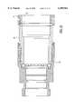
- FIG. 1is a longitudinal section through the center of a connector which embodies the present invention and a coaxial cable having an annularly corrugated outer conductor to be attached to one end of the connector, with the cable detached from the connector;
- FIG. 2is the same longitudinal section shown in FIG. 1 with the front portion of the connector attached to the coaxial cable, and the rear portion partially installed;
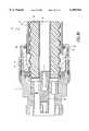
- FIG. 3is the same longitudinal section shown in FIG. 1 with the connector fully installed on the cable;
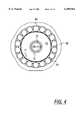
- FIG. 4is a section taken generally along the line 4--4 in FIG. 3;
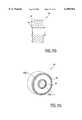
- FIG. 5is an end elevation taken from the front end of the connector that is shown in longitudinal section in FIG. 1;
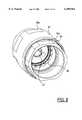
- FIG. 6is a perspective view taken from the front end of the connector assembly of FIGS. 1-5;
- FIG. 7is an end elevation taken from the rear end of the connector assembly of FIGS. 1-5;
- FIG. 8is a perspective view taken from the rear end of the connector assembly of FIGS. 1-5;
- FIG. 9ais a longitudinal section taken through the center of a modified connector embodying the invention.
- FIG. 9bis the same longitudinal section shown in FIG. 9a with the modified connector fully installed on the cable;
- FIG. 10is a longitudinal section taken through the center of another modified connector embodying the invention.
- FIG. 11ais a longitudinal section taken through the center of another modified connector embodying the invention.
- FIG. 11bis a cross-sectional view of an insulator for the modified connector of FIG. 11a taken along line 11b-11b in FIG. 11c;
- FIG. 11cis a perspective view of an insulator for the modified connector of FIG. 11a.
- FIG. 12is a longitudinal section taken through the center of another modified connector embodying the invention.
- an "annularly" corrugated conductoris distinguished from a “helically” corrugated conductor in that the annular corrugations form a series of spaced parallel crests which are discontinuous along the length of the cable and, similarly, a series of spaced parallel valleys which are also discontinuous along the length of the cable. That is, each crest and valley extends around the circumference of the conductor only once, until it meets itself, and does not continue in the longitudinal direction. Consequently, any transverse cross-section taken through the conductor perpendicular to its axis is radially symmetrical, which is not true of helically corrugated conductors.
- the end of the cable 10is cut along a plane extending through the apex of one of the crests of the corrugated outer conductor 11 and perpendicular to the axis of the cable 10. This exposes the clean and somewhat flared inner surface of the outer conductor 11.
- the foam dielectric 13normally does not fill the crests of the corrugated outer conductor 11, so a small area of the inner surface of the outer conductor 11 is exposed adjacent the cut end of the conductor 11 at the apex of the crest through which the cut is made.
- the foam in this regionis preferably compressed radially inward during cable preparation in order to provide sufficient clearance to permit contact with the inner surface of the outer conductor 11 adjacent the cut end thereof.
- any burrs or rough edges on the cut ends of the metal conductors 11, 12are preferably removed to avoid interference with the connector assembly 5.
- the outer surface of the outer conductor 11is normally covered with a plastic jacket 14 which is trimmed away from the end of the outer conductor 11 along a sufficient length to accommodate the connector assembly 5.
- the connector assembly 5includes a front body member 30, a rear body member 50 that telescopes under a portion of the front body member 30, and a bearing sleeve 41 that is captured within the rear body member 50.
- the bearing sleeve 41is connected to the rear body member 50 by a mechanical fastener.
- the mechanical fastenerincludes spring tabs that extend radially outward from the bearing sleeve 41 to lock into a corresponding groove disposed on the interior surface of the rear body member 50.
- the connector assembly 5is preferably sold as a one piece unit that requires no assembly by the user. This facilitates easy installation to the cable 10 and improves safety by reducing the likelihood that the installer will drop tools and/or a portion of the assembly 5 from dangerous heights as a result of struggling with several connector components.
- electrical contact with the inner conductor 12 of the cable 10is effected by an inner connector element 20 which includes a C-shaped spring 21 (illustrated in FIGS. 1-4).
- the C-shaped spring 21produces a tapered, or gradually increasing, spring force when inserted into the hollow inner conductor 12.
- the C-shaped spring 21thus makes a high force spring contact when fitted into the inner conductor 12.
- the spring 21includes a generally tubular section and a generally tubular end section having an end 24.
- the generally tubular sectionis adjacent and integral with the end section.
- the end sectionhas a single slit 25 extending longitudinally from the end 24 along the end section so as to form the C-shaped spring 21.
- the spring 21is resiliently adaptable to fit into the hollow inner conductor 12 to make good electrical contact.
- a set of spring fingers 22is formed on the opposite end of the inner connector element 20 for connecting the inner conductor 12 to a conventional complementary male member (not shown).
- An insulator 23centers the element 20 within the front body member 30 of the connector assembly 5 while electrically isolating the element 20 from the front body member 30. It will be noted that the interior of the front body member 30 includes a recess 31 for receiving the insulator 23, as is conventional in coaxial cable connectors.
- electrical contact with the inner conductor 12 of the cable 10is effected by a conventional inner connector element 20' forming multiple spring fingers 21' (illustrated in FIGS. 9a and 9b) which are deflected slightly inwardly as they are inserted into the hollow conductor 12, so that the resulting spring forces hold the spring fingers 21' tightly against the inside surface of the inner conductor 12.
- electrical contact with a solid inner conductoris effected by a connector element that includes a C-shaped female spring that makes a high force spring contact with the outer surface of the solid inner conductor when fitted over a portion of the solid inner conductor.
- electrical contact with a solid inner conductoris effected by a connector element that includes multiple female spring fingers that are adapted to fit over a portion of the solid inner conductor.
- the front body member 30includes a clamping surface 32 which engages the inner surface of the corrugated outer conductor 11 adjacent the last crest in the corrugated outer conductor 11.
- the clamping surface 32is conically beveled, as illustrated in FIGS. 1-3.
- the clamping surfacecan be radiused (or rounded), or form a generally square edge.
- the clamping surface 32is the end of an annulus 33 formed as an integral part of the interior of the front body member 30, and is continuous around the entire circumference of the cable to ensure good electrical contact with the inner surface of the outer conductor 11, as illustrated in FIG. 3.
- the clamping surface 32is preferably formed as an integral part of the front body member 30, rather than as a separate insert, to facilitate easy handling and installation of the connector assembly 5, particularly under field conditions where small parts are often dropped and lost. As the connector assembly 5 is telescoped over the cut end of the cable 10, the leading edge of the clamping surface 32 penetrates between the inner surface of the outer conductor 11 and the foam dielectric 13 and then progressively engages a major portion of the inner surface of the outer conductor 11 between the cut end and the first valley.
- a set of ball bearings 40is carried near one end of the annular bearing sleeve 41. More specifically, the ball bearings 40 are captured between the front body member 30 and the bearing sleeve 41, with each ball bearing 40 being seated in one of a series of tapered apertures 42 spaced around the circumference of the bearing sleeve 41.
- the apertures 42taper inwardly to a diameter that is only slightly smaller than that of the ball bearings 40, so that the radially inner portions of the ball bearings can project inwardly beyond the inside surface of the bearing sleeve 41.
- a cam surface 34 on the interior of the front body member 30engages the outer portions of the ball bearings 40 and presses the ball bearings into the apertures 42 so that the inner portions of the ball bearings 40 project through the apertures and fit into the last valley of the corrugated outer conductor 11 adjacent the end of the cable.
- the ball bearings 40thus clamp the end portion of the outer conductor 11 firmly against the clamping surface 32.
- a connecting meansdraws and holds the first and second body members 30 and 50 together. This draws the clamping surface 32 and the ball bearings 40 against the inner and outer surfaces, respectively, of the outer conductor 11.
- the connecting meansis a threaded connection between the first and second body members 30 and 50.
- the inner surface of the telescoping portion of the front body member 30includes a first threaded surface 35
- the outer surface of the telescoping portion of the rear body member 50includes a second threaded surface 52.
- the cooperating threaded surfaces 35 and 52are adapted to draw the clamping surface 32 and the ball bearings 40 firmly against opposite sides of the flared end portion of the outer conductor 11.
- the two members 30 and 50are rotated relative to each other in a first direction, they are advanced toward each other in the axial direction so as to draw the bearing sleeve 41 farther into the front body member 30, thus drawing the ball bearings 40 into firm engagement with the outer conductor 11.
- the annular flared end portion of the outer conductor 11is clamped between the clamping surface 32 and the ball bearings 40, the conductor 11 is pressed into firm mechanical and electrical contact with the clamping surfaces 32 to establish and maintain the desired electrical connection with the outer conductor 11.
- the front and rear body members 30 and 50are simply rotated relative to each other in the opposite direction to retract the rear body member 50, and thus the bearing sleeve 41, away from the front body member 30 until the ball bearings 40 are clear of the cam surface 34.
- the one piece connector assembly 5can then be slipped off the cable 10.
- wrench flats 30a and 50aare provided on the exterior surfaces of the front and rear body members 30 and 50, respectively, to receive tools, such as wrenches, for rotating the two members 30 and 50 relative to each other.
- the connecting meansincludes, for example, an air cylinder(s) attached to each of the respective body members 30 and 50 to move the two members together in a linear fashion.
- the connecting meansmay include an electromagnetic coil(s) attached to each of the respective body members 30 and 50 to move the two members together in a linear fashion.
- the connecting meansmay further include a bayonet mount.
- the connecting meansmay also simply press-fit or snap the two members 30 and 50 together.
- the ball bearings 40can move radially when they are not in contact with the cam surface 34, to permit them to pass over the crests of the corrugated outer conductor 11 when the bearing sleeve 41 is being moved longitudinally along the cable, during installation or removal. Consequently, when the connector assembly 5 is slipped over the cable 10 with the ball bearings 40 engaging the cut edge of the outer conductor 11, continued application of pressure to the connector assembly 5 causes the ball bearings 40 to be cammed radially outwardly by the outer conductor 11, as illustrated in FIG. 2. The ball bearings 40 are then cammed into the last valley of the corrugated outer conductor 11, as illustrated in FIG. 3, as the rear body member 50 is threaded to its fully advanced position with respect to the front body member 30, causing the cam surface 34 to press the ball bearings 40 firmly against the inner portions of the sidewalls of the tapered apertures 42, and against the outer conductor 11.
- the ball bearings 40minimize the frictional engagement between the front body member 30 and the bearing sleeve 41.
- the tightening of the connector assembly 5 on the cable 10can be effected quickly and efficiently with a minimum of tightening torque. This also minimizes any damage to plated surfaces and minimizes the generation of metal flakes generated by abrasion between the body members 30 and 50 and/or the outer conductor 11, which can adversely affect electrical performance.
- an O-ring 60is positioned in a groove formed by adjacent surfaces of the bearing sleeve 41 and the rear body member 50. Then when the rear body member 50 is advanced towards the front body member 30, an end flange 53 on the body member 50 presses the O-ring 60 against the bearing sleeve 41. This compresses the O-ring 60 so that it bears firmly against both the outer surface of the outer conductor 11 and the opposed surfaces of bearing sleeve 41 and the rear body member 50. As illustrated in FIG. 3, the O-ring 60 seals directly on a crest of the outer conductor 11.
- Sealing on the outer conductor 11provides a superior moister seal as compared with sealing on the cable jacket 14.
- a moisture barrier similar to that provided by the resilient O-ring 60is provided by a second O-ring 61 positioned between the opposed surfaces of a portion of the rear body member 50 and a telescoping portion of the front body member 30.
- the O-rings 60 and 61are coated with a dry film lubrication.
- the typical factory applied grease or wax lubricant used in prior connectorstends to dry out over time.
- the present inventioneliminates the need to apply lubricant in the field during installation or thereafter.
- a moisture barrier similar to that provided by the resilient O-rings 60 and 61is provided by O-rings 62 and 63 in order to provide a sealed interface.
- a third O-ring 62is positioned between the insulator 23 and the opposed surface of the front portion of the front body member 30.
- a fourth O-ring 63is positioned between the insulator 23 and the opposed surface of the inner connector element 20.
- the inner surface of a fifth O-ring 64is exposed for resiliently engaging the outer surface of the inner connector element 20.
- the O-ring 64inhibits metal chips that may be disposed in the hollow inner conductor 12 from entering the connector assembly 5 and causing interference. Such metal chips are usually produced during the installation process by cutting the cable 10.
- FIGS. 9a and 9billustrate a modified connector in which the rear body member 70 telescopes along the outside surface, rather than along the inside surface, of the front body member 71.
- the first threaded surface 72is on the outside surface of the front body member 71
- second threaded surface 73is on the inside surface of the rear body member 70.
- the exposed surface of the O-ring 60'bears firmly against the outer surface of the cable jacket 14, as opposed to the outer conductor 11. This provides a moisture barrier between the outer surface of the cable jacket 14 and the inner surfaces of the bearing sleeve 74 and the rear body member 70.
- the operation of this connector assemblyis substantially similar to the embodiment of FIGS. 1-8 described above.
- FIG. 10illustrates another modified connector in which the bearing sleeve 80, rather than the rear body member 81, is threaded into the front body member 82.
- the rear body member 81threads into the end of the bearing sleeve 80 and is used to position and compress the O-ring 83 therebetween.
- the O-ring 83forms a moisture seal between the cable jacket and the modified connector assembly once the cable is inserted into the modified connector assembly.
- FIGS. 11a-cillustrate another modified connector 85.
- a simple plastic insulator press fit into the metal front body member 100is not sufficient because of the large difference in temperature expansion coefficients between plastic and metal, and the constraining effects of the front body member 100 at high temperatures. This will cause the plastic insulator to "cold flow", resulting in a reduced outer diameter and an elongated length of the plastic insulator after temperature cycling. The reduced outer diameter will result in a leak path between the insulator and the front body member 100 after the insulator returns to ambient temperature. Therefore, it is necessary to have some type of resilient sealing mechanism that can adjust to accommodate the dimensional changes that occur due to temperature cycling, without being constrained by the front body member 100.
- an insulator 90is used in one embodiment of the claimed invention to provide a resilient seal.
- This insulator 90is molded with a pair of integral resilient sealing rings 92 and 94.
- the outer diameter of the sealing rings 92 and 94is not constrained by the front body member 100. Instead, the sealing rings 92 and 94 are free to flex and move with temperature cycling and can expand as temperatures increase without being forced to "cold flow”.
- the outer sealing ring 92fits into a mating groove 96 in the front body member 100.
- the mating groove 96allows good sealing performance to be maintained between the front body member 100 and the insulator 90, even at cold temperatures, because the groove 96 serves to increase the sealing pressure as the insulator 90 shrinks relative to the front body member 100.
- the groove 96allows the outer sealing ring 92 to shrink at substantially the same rate, at cold temperatures, as the front body member 100. This minimizes the likelihood of a leak path between the outside environment and the hollow inner conductor 12.
- the inner sealing ring 94seals adjacent to the inner connector element 98 in the front body member 100 to minimizes the likelihood of a leak path between the outside environment and the hollow inner conductor 12.
- FIG. 12illustrates a modified connector in which the rear body member 110 telescopes along the outside surface, rather than the inside surface, of the front body member 112.
- the first threaded surface 114is on the outside surface of the front body member 112
- the second threaded surface 116is on the inside surface of the rear body member 110.
- the exposed surface of an O-ring 160bears firmly against the outer conductor 11, as opposed to the outer surface of the cable jacket 14. This provides a moisture barrier between the outer conductor 11 and the inner surfaces of the bearing sleeve 118 and the rear body member 110.
- the improved connector assembly 5is easy to install, remove, and re-install, even under adverse field conditions. All the parts of the connector assembly 5 can be pre-assembled into a one piece connector, so that the possibility of dropping and losing small parts in the field is minimized. Also, the connector assembly 5 can be easily installed, and removed, with the use of conventional tools, so that no special equipment is required. Moreover, the connector assembly provides positive electrical contact, particularly with the annularly corrugated outer conductor, to ensure reliable electrical performance. Furthermore, the connector assembly 5 can be efficiently and economically manufactured so that all the practical and performance advantages of the connector assembly 5 are achieved without any significant economic sacrifice.
Landscapes
- Coupling Device And Connection With Printed Circuit (AREA)
Abstract
Description
Claims (40)
Priority Applications (1)
| Application Number | Priority Date | Filing Date | Title |
|---|---|---|---|
| US09/271,390US6109964A (en) | 1998-04-06 | 1999-03-19 | One piece connector for a coaxial cable with an annularly corrugated outer conductor |
Applications Claiming Priority (2)
| Application Number | Priority Date | Filing Date | Title |
|---|---|---|---|
| US8080398P | 1998-04-06 | 1998-04-06 | |
| US09/271,390US6109964A (en) | 1998-04-06 | 1999-03-19 | One piece connector for a coaxial cable with an annularly corrugated outer conductor |
Publications (1)
| Publication Number | Publication Date |
|---|---|
| US6109964Atrue US6109964A (en) | 2000-08-29 |
Family
ID=22159723
Family Applications (1)
| Application Number | Title | Priority Date | Filing Date |
|---|---|---|---|
| US09/271,390Expired - LifetimeUS6109964A (en) | 1998-04-06 | 1999-03-19 | One piece connector for a coaxial cable with an annularly corrugated outer conductor |
Country Status (6)
| Country | Link |
|---|---|
| US (1) | US6109964A (en) |
| EP (1) | EP0955701A3 (en) |
| JP (1) | JPH11345659A (en) |
| KR (1) | KR19990082862A (en) |
| CN (1) | CN1110874C (en) |
| BR (1) | BR9901237A (en) |
Cited By (51)
| Publication number | Priority date | Publication date | Assignee | Title |
|---|---|---|---|---|
| US6217383B1 (en)* | 2000-06-21 | 2001-04-17 | Holland Electronics, Llc | Coaxial cable connector |
| US20030148660A1 (en)* | 2002-02-04 | 2003-08-07 | Devine Edward B. | Watertight device for connecting a transmission line connector to a signal source connector |
| US6699054B1 (en)* | 2003-01-15 | 2004-03-02 | Applied Engineering Products, Inc. | Float mount coaxial connector |
| US6705884B1 (en) | 1999-08-16 | 2004-03-16 | Centerpin Technology, Inc. | Electrical connector apparatus and method |
| GB2394126A (en)* | 2002-09-12 | 2004-04-14 | Andrew Corp | Connector for a coaxial cable |
| US6733336B1 (en) | 2003-04-03 | 2004-05-11 | John Mezzalingua Associates, Inc. | Compression-type hard-line connector |
| US6793529B1 (en)* | 2003-09-30 | 2004-09-21 | Andrew Corporation | Coaxial connector with positive stop clamping nut attachment |
| US6824415B2 (en) | 2001-11-01 | 2004-11-30 | Andrew Corporation | Coaxial connector with spring loaded coupling mechanism |
| US6890208B2 (en) | 2000-03-03 | 2005-05-10 | Centerpin Technology, Inc. | Electrical connector apparatus and method |
| WO2006069972A1 (en)* | 2004-12-30 | 2006-07-06 | See Sprl | Coaxial connectors |
| US7126064B1 (en) | 2005-08-22 | 2006-10-24 | Sami Shemtov | Connector for affixing cables within junction boxes |
| US7189115B1 (en) | 2005-12-29 | 2007-03-13 | John Mezzalingua Associates, Inc. | Connector for spiral corrugated coaxial cable and method of use thereof |
| EP1206011B1 (en)* | 2000-11-14 | 2007-05-30 | Radio Frequency Systems Inc. | One step connector |
| US20070161288A1 (en)* | 2004-10-06 | 2007-07-12 | Rosenberger Hochfrequenztechnik Gmbh | Coaxial insertion connected connector having quick action locking mechanism |
| US20090053931A1 (en)* | 2007-08-22 | 2009-02-26 | Andrew Llc | Sealed Inner Conductor Contact for Coaxial Cable Connector |
| US20090130900A1 (en)* | 2007-11-21 | 2009-05-21 | Jens Petersen | Coaxial Cable Connector For Corrugated Cable |
| US20090186521A1 (en)* | 2008-01-22 | 2009-07-23 | Andrew Llc | Locking threaded connection coaxial connector |
| US20090197465A1 (en)* | 2007-05-02 | 2009-08-06 | John Mezzalingua Associates, Inc. | Compression connector for coaxial cable with staggered seizure of outer and center conductor |
| US20090233482A1 (en)* | 2007-05-02 | 2009-09-17 | Shawn Chawgo | Compression Connector For Coaxial Cable |
| US7632143B1 (en) | 2008-11-24 | 2009-12-15 | Andrew Llc | Connector with positive stop and compressible ring for coaxial cable and associated methods |
| US7635283B1 (en) | 2008-11-24 | 2009-12-22 | Andrew Llc | Connector with retaining ring for coaxial cable and associated methods |
| US20100087090A1 (en)* | 2008-10-07 | 2010-04-08 | Andrew Llc | Inner Conductor Sealing Insulator for Coaxial Connector |
| US20100130060A1 (en)* | 2008-11-24 | 2010-05-27 | Andrew, Llc | Connector including compressible ring for clamping a conductor of a coaxial cable and associated methods |
| US20100126011A1 (en)* | 2008-11-24 | 2010-05-27 | Andrew, Llc, State/Country Of Incorporation: North Carolina | Flaring coaxial cable end preparation tool and associated methods |
| US7753727B1 (en)* | 2009-05-22 | 2010-07-13 | Andrew Llc | Threaded crimp coaxial connector |
| US20100190377A1 (en)* | 2009-01-28 | 2010-07-29 | Andrew Llc, State/Country Of Incorporation: Delaware | Connector including flexible fingers and associated methods |
| US7785144B1 (en) | 2008-11-24 | 2010-08-31 | Andrew Llc | Connector with positive stop for coaxial cable and associated methods |
| US20100233903A1 (en)* | 2009-03-10 | 2010-09-16 | Andrew Llc | Inner conductor end contacting coaxial connector and inner conductor adapter kit |
| US20100261382A1 (en)* | 2009-04-10 | 2010-10-14 | John Mezzalingua Associates, Inc. | Compression coaxial cable connector with center insulator seizing mechanism |
| US20100273340A1 (en)* | 2009-04-24 | 2010-10-28 | Jan Michael Clausen | Coaxial Connector For Corrugated Cable With Corrugated Sealing |
| US8047870B2 (en) | 2009-01-09 | 2011-11-01 | Corning Gilbert Inc. | Coaxial connector for corrugated cable |
| US8177583B2 (en) | 2007-05-02 | 2012-05-15 | John Mezzalingua Associates, Inc. | Compression connector for coaxial cable |
| US20120142207A1 (en)* | 2010-12-02 | 2012-06-07 | Thomas & Betts International, Inc. | Cable connector with retaining element |
| US8298006B2 (en) | 2010-10-08 | 2012-10-30 | John Mezzalingua Associates, Inc. | Connector contact for tubular center conductor |
| US8430688B2 (en) | 2010-10-08 | 2013-04-30 | John Mezzalingua Associates, LLC | Connector assembly having deformable clamping surface |
| US8435073B2 (en) | 2010-10-08 | 2013-05-07 | John Mezzalingua Associates, LLC | Connector assembly for corrugated coaxial cable |
| US8439703B2 (en) | 2010-10-08 | 2013-05-14 | John Mezzalingua Associates, LLC | Connector assembly for corrugated coaxial cable |
| US8449325B2 (en) | 2010-10-08 | 2013-05-28 | John Mezzalingua Associates, LLC | Connector assembly for corrugated coaxial cable |
| US8458898B2 (en) | 2010-10-28 | 2013-06-11 | John Mezzalingua Associates, LLC | Method of preparing a terminal end of a corrugated coaxial cable for termination |
| CN103166071A (en)* | 2011-12-15 | 2013-06-19 | 西安富士达科技股份有限公司 | L29 type inserting hole contact element radio-frequency coaxial connector connected with 1-1/4' ring-shaped cable in matching mode |
| US8628352B2 (en) | 2011-07-07 | 2014-01-14 | John Mezzalingua Associates, LLC | Coaxial cable connector assembly |
| US8708737B2 (en) | 2010-04-02 | 2014-04-29 | John Mezzalingua Associates, LLC | Cable connectors having a jacket seal |
| CN104409876A (en)* | 2014-12-16 | 2015-03-11 | 中国工程物理研究院流体物理研究所 | Sealing connector for high-voltage coaxial cable |
| US9017102B2 (en) | 2012-02-06 | 2015-04-28 | John Mezzalingua Associates, LLC | Port assembly connector for engaging a coaxial cable and an outer conductor |
| US9083113B2 (en) | 2012-01-11 | 2015-07-14 | John Mezzalingua Associates, LLC | Compression connector for clamping/seizing a coaxial cable and an outer conductor |
| US9099825B2 (en) | 2012-01-12 | 2015-08-04 | John Mezzalingua Associates, LLC | Center conductor engagement mechanism |
| US9172156B2 (en) | 2010-10-08 | 2015-10-27 | John Mezzalingua Associates, LLC | Connector assembly having deformable surface |
| US10396511B2 (en)* | 2017-03-08 | 2019-08-27 | Commscope Technologies Llc | Corrugated cable co-axial connector |
| WO2020172687A1 (en)* | 2019-02-22 | 2020-08-27 | Ppc Broadband, Inc. | Coaxial cable connector sleeve with cutout |
| USD896758S1 (en) | 2019-02-22 | 2020-09-22 | Ppc Broadband, Inc. | Connector sleeve with cutout |
| US20220216658A1 (en)* | 2021-01-05 | 2022-07-07 | CommScope Place SE | Coaxial cable and connector assemblies |
Families Citing this family (20)
| Publication number | Priority date | Publication date | Assignee | Title |
|---|---|---|---|---|
| US6331123B1 (en)* | 2000-11-20 | 2001-12-18 | Thomas & Betts International, Inc. | Connector for hard-line coaxial cable |
| US6994587B2 (en)* | 2003-07-23 | 2006-02-07 | Andrew Corporation | Coaxial cable connector installable with common tools |
| EP1501159A1 (en)* | 2003-07-23 | 2005-01-26 | Andrew Corporation | Coaxial cable connector installable with common tools |
| KR100808875B1 (en)* | 2006-08-14 | 2008-03-03 | 삼성전자주식회사 | Coaxial Cable Connectors and Coaxial Cable Connectors Including the Same |
| DE102007022744A1 (en) | 2007-02-27 | 2008-08-28 | Rohde & Schwarz Gmbh & Co. Kg | Coaxial plug connection part, has coupling nut screwable with outer thread of counter-plug connection part for producing contact pressure between outer conductor front contact surfaces of plug connector |
| CN101420081B (en)* | 2007-10-27 | 2012-04-18 | 贵州航天电器股份有限公司 | Fast locking and detaching mechanism applied to coaxial electric connector |
| DE102008018809A1 (en)* | 2008-04-15 | 2009-10-22 | Rohde & Schwarz Gmbh & Co. Kg | Coaxial connector with ball bearing |
| KR101043744B1 (en)* | 2009-03-23 | 2011-06-27 | 주식회사 텔콘 | RF cable connector |
| US7867025B2 (en)* | 2009-05-29 | 2011-01-11 | John Mezzalingua, Associates, Inc. | Cable connector with supported center conductor contact |
| CN102176581A (en)* | 2011-02-22 | 2011-09-07 | 安德鲁公司 | Double-sealing structure of radio frequency coaxial connector and related radio frequency coaxial connector |
| KR101234659B1 (en)* | 2011-08-24 | 2013-02-22 | 주식회사 텔콘 | Rf connecter |
| KR101225048B1 (en)* | 2011-12-15 | 2013-01-22 | 연합정밀주식회사 | Round Composite Connector for Composite Cable |
| CN103047093A (en)* | 2013-01-07 | 2013-04-17 | 上海双菱风能电力设备有限公司 | Reliable movable connection device for high-power fan cable |
| CN103943255A (en)* | 2014-03-13 | 2014-07-23 | 江苏德诚冶金电炉设备有限公司 | Ball-type rotatable water-cooled cable |
| KR101725973B1 (en)* | 2016-10-12 | 2017-04-11 | 서울엔지니어링 주식회사 | Dredge machinery unification dredging and transporting of dredging sand, and method for dredging dredging sand |
| CN107768940A (en)* | 2017-11-10 | 2018-03-06 | 镇江华京通讯科技有限公司 | A kind of Novel radio frequency coaxial connector |
| KR101964000B1 (en) | 2018-01-17 | 2019-04-01 | (주)신광티앤이 | RF coaxial cable connector module |
| KR102139275B1 (en)* | 2018-10-11 | 2020-07-29 | 한국원자력연구원 | Sealing plug for sianal transmission |
| WO2021065702A1 (en)* | 2019-10-04 | 2021-04-08 | 株式会社村田製作所 | Probe |
| CN114079200B (en)* | 2020-08-11 | 2023-12-26 | 正凌精密工业(广东)有限公司 | Connector with direct locking and rotating pre-ejection function |
Citations (12)
| Publication number | Priority date | Publication date | Assignee | Title |
|---|---|---|---|---|
| US3199061A (en)* | 1963-01-31 | 1965-08-03 | Andrew Corp | Coaxial connector |
| US3291895A (en)* | 1964-05-05 | 1966-12-13 | Andrew Corp | Coaxial cable connectors |
| US4046451A (en)* | 1976-07-08 | 1977-09-06 | Andrew Corporation | Connector for coaxial cable with annularly corrugated outer conductor |
| US5021010A (en)* | 1990-09-27 | 1991-06-04 | Gte Products Corporation | Soldered connector for a shielded coaxial cable |
| US5137470A (en)* | 1991-06-04 | 1992-08-11 | Andrew Corporation | Connector for coaxial cable having a helically corrugated inner conductor |
| US5154636A (en)* | 1991-01-15 | 1992-10-13 | Andrew Corporation | Self-flaring connector for coaxial cable having a helically corrugated outer conductor |
| US5167533A (en)* | 1992-01-08 | 1992-12-01 | Andrew Corporation | Connector for coaxial cable having hollow inner conductors |
| US5354217A (en)* | 1993-06-10 | 1994-10-11 | Andrew Corporation | Lightweight connector for a coaxial cable |
| US5435745A (en)* | 1994-05-31 | 1995-07-25 | Andrew Corporation | Connector for coaxial cable having corrugated outer conductor |
| US5561900A (en)* | 1993-05-14 | 1996-10-08 | The Whitaker Corporation | Method of attaching coaxial connector to coaxial cable |
| US5567171A (en)* | 1993-10-08 | 1996-10-22 | Hirose Electric Co., Ltd. | Electrical connector with a latch |
| US5802710A (en)* | 1996-10-24 | 1998-09-08 | Andrew Corporation | Method of attaching a connector to a coaxial cable and the resulting assembly |
Family Cites Families (6)
| Publication number | Priority date | Publication date | Assignee | Title |
|---|---|---|---|---|
| US4801274A (en)* | 1988-01-15 | 1989-01-31 | Hewlett-Packard Company | Microwave coaxial connector device |
| US5284449A (en)* | 1993-05-13 | 1994-02-08 | Amphenol Corporation | Connector for a conduit with an annularly corrugated outer casing |
| JP2916665B2 (en)* | 1994-06-28 | 1999-07-05 | 三菱電線工業株式会社 | connector |
| JP2913373B2 (en)* | 1995-01-12 | 1999-06-28 | 三菱電線工業株式会社 | Method of connecting ring-shaped corrugated tube and connection structure thereof |
| CA2181840C (en)* | 1995-08-04 | 2000-05-16 | Lee F. Allison | Connector for coaxial cable |
| US5795188A (en)* | 1996-03-28 | 1998-08-18 | Andrew Corporation | Connector kit for a coaxial cable, method of attachment and the resulting assembly |
- 1999
- 1999-03-19USUS09/271,390patent/US6109964A/ennot_activeExpired - Lifetime
- 1999-03-29EPEP99106426Apatent/EP0955701A3/ennot_activeWithdrawn
- 1999-04-02KRKR1019990011538Apatent/KR19990082862A/ennot_activeCeased
- 1999-04-05BRBR9901237-5Apatent/BR9901237A/enactiveSearch and Examination
- 1999-04-06JPJP11098611Apatent/JPH11345659A/ennot_activeWithdrawn
- 1999-04-06CNCN99104928Apatent/CN1110874C/ennot_activeExpired - Fee Related
Patent Citations (12)
| Publication number | Priority date | Publication date | Assignee | Title |
|---|---|---|---|---|
| US3199061A (en)* | 1963-01-31 | 1965-08-03 | Andrew Corp | Coaxial connector |
| US3291895A (en)* | 1964-05-05 | 1966-12-13 | Andrew Corp | Coaxial cable connectors |
| US4046451A (en)* | 1976-07-08 | 1977-09-06 | Andrew Corporation | Connector for coaxial cable with annularly corrugated outer conductor |
| US5021010A (en)* | 1990-09-27 | 1991-06-04 | Gte Products Corporation | Soldered connector for a shielded coaxial cable |
| US5154636A (en)* | 1991-01-15 | 1992-10-13 | Andrew Corporation | Self-flaring connector for coaxial cable having a helically corrugated outer conductor |
| US5137470A (en)* | 1991-06-04 | 1992-08-11 | Andrew Corporation | Connector for coaxial cable having a helically corrugated inner conductor |
| US5167533A (en)* | 1992-01-08 | 1992-12-01 | Andrew Corporation | Connector for coaxial cable having hollow inner conductors |
| US5561900A (en)* | 1993-05-14 | 1996-10-08 | The Whitaker Corporation | Method of attaching coaxial connector to coaxial cable |
| US5354217A (en)* | 1993-06-10 | 1994-10-11 | Andrew Corporation | Lightweight connector for a coaxial cable |
| US5567171A (en)* | 1993-10-08 | 1996-10-22 | Hirose Electric Co., Ltd. | Electrical connector with a latch |
| US5435745A (en)* | 1994-05-31 | 1995-07-25 | Andrew Corporation | Connector for coaxial cable having corrugated outer conductor |
| US5802710A (en)* | 1996-10-24 | 1998-09-08 | Andrew Corporation | Method of attaching a connector to a coaxial cable and the resulting assembly |
Cited By (76)
| Publication number | Priority date | Publication date | Assignee | Title |
|---|---|---|---|---|
| US6705884B1 (en) | 1999-08-16 | 2004-03-16 | Centerpin Technology, Inc. | Electrical connector apparatus and method |
| US6890208B2 (en) | 2000-03-03 | 2005-05-10 | Centerpin Technology, Inc. | Electrical connector apparatus and method |
| US6217383B1 (en)* | 2000-06-21 | 2001-04-17 | Holland Electronics, Llc | Coaxial cable connector |
| EP1206011B1 (en)* | 2000-11-14 | 2007-05-30 | Radio Frequency Systems Inc. | One step connector |
| US6824415B2 (en) | 2001-11-01 | 2004-11-30 | Andrew Corporation | Coaxial connector with spring loaded coupling mechanism |
| US20030148660A1 (en)* | 2002-02-04 | 2003-08-07 | Devine Edward B. | Watertight device for connecting a transmission line connector to a signal source connector |
| US7029327B2 (en) | 2002-02-04 | 2006-04-18 | Andrew Corporation | Watertight device for connecting a transmission line connector to a signal source connector |
| GB2394126A (en)* | 2002-09-12 | 2004-04-14 | Andrew Corp | Connector for a coaxial cable |
| GB2394126B (en)* | 2002-09-12 | 2005-11-02 | Andrew Corp | Coaxial cable connector |
| US6699054B1 (en)* | 2003-01-15 | 2004-03-02 | Applied Engineering Products, Inc. | Float mount coaxial connector |
| US6733336B1 (en) | 2003-04-03 | 2004-05-11 | John Mezzalingua Associates, Inc. | Compression-type hard-line connector |
| US6793529B1 (en)* | 2003-09-30 | 2004-09-21 | Andrew Corporation | Coaxial connector with positive stop clamping nut attachment |
| US7510432B2 (en)* | 2004-10-06 | 2009-03-31 | Rosenberger Hochfrequenztechnik Gmbh & Co. Kg | Coaxial insertion connected connector having quick action locking mechanism |
| US20070161288A1 (en)* | 2004-10-06 | 2007-07-12 | Rosenberger Hochfrequenztechnik Gmbh | Coaxial insertion connected connector having quick action locking mechanism |
| US20090053928A9 (en)* | 2004-10-06 | 2009-02-26 | Rosenberger Hochfrequenztechnik Gmbh | Coaxial insertion connected connector having quick action locking mechanism |
| WO2006069972A1 (en)* | 2004-12-30 | 2006-07-06 | See Sprl | Coaxial connectors |
| US7207838B2 (en) | 2004-12-30 | 2007-04-24 | See Sprl | Coaxial connectors |
| US20060148315A1 (en)* | 2004-12-30 | 2006-07-06 | Paul Andreescu | Coaxial connectors |
| US7126064B1 (en) | 2005-08-22 | 2006-10-24 | Sami Shemtov | Connector for affixing cables within junction boxes |
| US7189115B1 (en) | 2005-12-29 | 2007-03-13 | John Mezzalingua Associates, Inc. | Connector for spiral corrugated coaxial cable and method of use thereof |
| US8123557B2 (en) | 2007-05-02 | 2012-02-28 | John Mezzalingua Associates, Inc. | Compression connector for coaxial cable with staggered seizure of outer and center conductor |
| US20090197465A1 (en)* | 2007-05-02 | 2009-08-06 | John Mezzalingua Associates, Inc. | Compression connector for coaxial cable with staggered seizure of outer and center conductor |
| US20090233482A1 (en)* | 2007-05-02 | 2009-09-17 | Shawn Chawgo | Compression Connector For Coaxial Cable |
| US8177583B2 (en) | 2007-05-02 | 2012-05-15 | John Mezzalingua Associates, Inc. | Compression connector for coaxial cable |
| US8007314B2 (en) | 2007-05-02 | 2011-08-30 | John Mezzalingua Associates, Inc. | Compression connector for coaxial cable |
| US7819698B2 (en)* | 2007-08-22 | 2010-10-26 | Andrew Llc | Sealed inner conductor contact for coaxial cable connector |
| US20090053931A1 (en)* | 2007-08-22 | 2009-02-26 | Andrew Llc | Sealed Inner Conductor Contact for Coaxial Cable Connector |
| US20090130900A1 (en)* | 2007-11-21 | 2009-05-21 | Jens Petersen | Coaxial Cable Connector For Corrugated Cable |
| US7690945B2 (en) | 2007-11-21 | 2010-04-06 | Corning Gilbert Inc. | Coaxial cable connector for corrugated cable |
| US7661984B2 (en) | 2008-01-22 | 2010-02-16 | Andrew Llc | Locking threaded connection coaxial connector |
| US20090186521A1 (en)* | 2008-01-22 | 2009-07-23 | Andrew Llc | Locking threaded connection coaxial connector |
| US20100087090A1 (en)* | 2008-10-07 | 2010-04-08 | Andrew Llc | Inner Conductor Sealing Insulator for Coaxial Connector |
| US7798847B2 (en) | 2008-10-07 | 2010-09-21 | Andrew Llc | Inner conductor sealing insulator for coaxial connector |
| US8136234B2 (en) | 2008-11-24 | 2012-03-20 | Andrew Llc | Flaring coaxial cable end preparation tool and associated methods |
| US7785144B1 (en) | 2008-11-24 | 2010-08-31 | Andrew Llc | Connector with positive stop for coaxial cable and associated methods |
| US20100130060A1 (en)* | 2008-11-24 | 2010-05-27 | Andrew, Llc | Connector including compressible ring for clamping a conductor of a coaxial cable and associated methods |
| US7731529B1 (en) | 2008-11-24 | 2010-06-08 | Andrew Llc | Connector including compressible ring for clamping a conductor of a coaxial cable and associated methods |
| US7635283B1 (en) | 2008-11-24 | 2009-12-22 | Andrew Llc | Connector with retaining ring for coaxial cable and associated methods |
| US7632143B1 (en) | 2008-11-24 | 2009-12-15 | Andrew Llc | Connector with positive stop and compressible ring for coaxial cable and associated methods |
| US20100126011A1 (en)* | 2008-11-24 | 2010-05-27 | Andrew, Llc, State/Country Of Incorporation: North Carolina | Flaring coaxial cable end preparation tool and associated methods |
| US8047870B2 (en) | 2009-01-09 | 2011-11-01 | Corning Gilbert Inc. | Coaxial connector for corrugated cable |
| US20100190377A1 (en)* | 2009-01-28 | 2010-07-29 | Andrew Llc, State/Country Of Incorporation: Delaware | Connector including flexible fingers and associated methods |
| US7931499B2 (en) | 2009-01-28 | 2011-04-26 | Andrew Llc | Connector including flexible fingers and associated methods |
| US7803018B1 (en)* | 2009-03-10 | 2010-09-28 | Andrew Llc | Inner conductor end contacting coaxial connector and inner conductor adapter kit |
| US20100233903A1 (en)* | 2009-03-10 | 2010-09-16 | Andrew Llc | Inner conductor end contacting coaxial connector and inner conductor adapter kit |
| US8038472B2 (en) | 2009-04-10 | 2011-10-18 | John Mezzalingua Associates, Inc. | Compression coaxial cable connector with center insulator seizing mechanism |
| US20100261382A1 (en)* | 2009-04-10 | 2010-10-14 | John Mezzalingua Associates, Inc. | Compression coaxial cable connector with center insulator seizing mechanism |
| US20100273340A1 (en)* | 2009-04-24 | 2010-10-28 | Jan Michael Clausen | Coaxial Connector For Corrugated Cable With Corrugated Sealing |
| US8113878B2 (en) | 2009-04-24 | 2012-02-14 | Corning Gilbert Inc. | Coaxial connector for corrugated cable with corrugated sealing |
| US7753727B1 (en)* | 2009-05-22 | 2010-07-13 | Andrew Llc | Threaded crimp coaxial connector |
| US8956184B2 (en) | 2010-04-02 | 2015-02-17 | John Mezzalingua Associates, LLC | Coaxial cable connector |
| US8708737B2 (en) | 2010-04-02 | 2014-04-29 | John Mezzalingua Associates, LLC | Cable connectors having a jacket seal |
| US8430688B2 (en) | 2010-10-08 | 2013-04-30 | John Mezzalingua Associates, LLC | Connector assembly having deformable clamping surface |
| US9172156B2 (en) | 2010-10-08 | 2015-10-27 | John Mezzalingua Associates, LLC | Connector assembly having deformable surface |
| US8439703B2 (en) | 2010-10-08 | 2013-05-14 | John Mezzalingua Associates, LLC | Connector assembly for corrugated coaxial cable |
| US8449325B2 (en) | 2010-10-08 | 2013-05-28 | John Mezzalingua Associates, LLC | Connector assembly for corrugated coaxial cable |
| US9276363B2 (en) | 2010-10-08 | 2016-03-01 | John Mezzalingua Associates, LLC | Connector assembly for corrugated coaxial cable |
| US8435073B2 (en) | 2010-10-08 | 2013-05-07 | John Mezzalingua Associates, LLC | Connector assembly for corrugated coaxial cable |
| US8298006B2 (en) | 2010-10-08 | 2012-10-30 | John Mezzalingua Associates, Inc. | Connector contact for tubular center conductor |
| US8458898B2 (en) | 2010-10-28 | 2013-06-11 | John Mezzalingua Associates, LLC | Method of preparing a terminal end of a corrugated coaxial cable for termination |
| US8657626B2 (en)* | 2010-12-02 | 2014-02-25 | Thomas & Betts International, Inc. | Cable connector with retaining element |
| US20120142207A1 (en)* | 2010-12-02 | 2012-06-07 | Thomas & Betts International, Inc. | Cable connector with retaining element |
| US9214771B2 (en) | 2011-06-01 | 2015-12-15 | John Mezzalingua Associates, LLC | Connector for a cable |
| US8628352B2 (en) | 2011-07-07 | 2014-01-14 | John Mezzalingua Associates, LLC | Coaxial cable connector assembly |
| CN103166071A (en)* | 2011-12-15 | 2013-06-19 | 西安富士达科技股份有限公司 | L29 type inserting hole contact element radio-frequency coaxial connector connected with 1-1/4' ring-shaped cable in matching mode |
| US9083113B2 (en) | 2012-01-11 | 2015-07-14 | John Mezzalingua Associates, LLC | Compression connector for clamping/seizing a coaxial cable and an outer conductor |
| US9099825B2 (en) | 2012-01-12 | 2015-08-04 | John Mezzalingua Associates, LLC | Center conductor engagement mechanism |
| US9017102B2 (en) | 2012-02-06 | 2015-04-28 | John Mezzalingua Associates, LLC | Port assembly connector for engaging a coaxial cable and an outer conductor |
| CN104409876A (en)* | 2014-12-16 | 2015-03-11 | 中国工程物理研究院流体物理研究所 | Sealing connector for high-voltage coaxial cable |
| US10396511B2 (en)* | 2017-03-08 | 2019-08-27 | Commscope Technologies Llc | Corrugated cable co-axial connector |
| WO2020172687A1 (en)* | 2019-02-22 | 2020-08-27 | Ppc Broadband, Inc. | Coaxial cable connector sleeve with cutout |
| USD896758S1 (en) | 2019-02-22 | 2020-09-22 | Ppc Broadband, Inc. | Connector sleeve with cutout |
| US11005212B2 (en) | 2019-02-22 | 2021-05-11 | Ppc Broadband, Inc. | Coaxial cable connector sleeve with cutout |
| US11646530B2 (en) | 2019-02-22 | 2023-05-09 | Ppc Broadband, Inc. | Coaxial cable connector sleeve with cutout |
| US20220216658A1 (en)* | 2021-01-05 | 2022-07-07 | CommScope Place SE | Coaxial cable and connector assemblies |
| WO2022150169A1 (en)* | 2021-01-05 | 2022-07-14 | Commscope Technologies Llc | Coaxial cable and connector assemblies |
Also Published As
| Publication number | Publication date |
|---|---|
| CN1110874C (en) | 2003-06-04 |
| JPH11345659A (en) | 1999-12-14 |
| EP0955701A3 (en) | 2000-05-17 |
| BR9901237A (en) | 2000-01-18 |
| CN1231531A (en) | 1999-10-13 |
| EP0955701A2 (en) | 1999-11-10 |
| KR19990082862A (en) | 1999-11-25 |
Similar Documents
| Publication | Publication Date | Title |
|---|---|---|
| US6109964A (en) | One piece connector for a coaxial cable with an annularly corrugated outer conductor | |
| US5137470A (en) | Connector for coaxial cable having a helically corrugated inner conductor | |
| US7104839B2 (en) | Coaxial connector with center conductor seizure | |
| US5284449A (en) | Connector for a conduit with an annularly corrugated outer casing | |
| US8465322B2 (en) | Coaxial cable connector | |
| US7077699B2 (en) | Axial compression electrical connector | |
| US5154636A (en) | Self-flaring connector for coaxial cable having a helically corrugated outer conductor | |
| EP0798815B1 (en) | Electrical connector assembly for a coaxial cable having a corrugated outer conductor | |
| EP0657068B1 (en) | Connector for coaxial cable having corrugated outer conductor and method of attachment | |
| US6790081B2 (en) | Sealed coaxial cable connector and related method | |
| US6386915B1 (en) | One step connector | |
| EP2551966B1 (en) | Electric connector with a cable clamping portion | |
| US9257780B2 (en) | Coaxial cable connector with weather seal | |
| US7261581B2 (en) | Coaxial connector and method | |
| US8342879B2 (en) | Coaxial cable connector | |
| MX2008004953A (en) | Adjustable connector for electrical cable. | |
| US20240079817A1 (en) | Coupler seal for coaxial cable system components | |
| US9033730B2 (en) | Coaxial cable connector and method of making same |
Legal Events
| Date | Code | Title | Description |
|---|---|---|---|
| AS | Assignment | Owner name:ANDREW CORPORATION, ILLINOIS Free format text:ASSIGNMENT OF ASSIGNORS INTEREST;ASSIGNOR:KOOIMAN, JOHN A.;REEL/FRAME:009844/0025 Effective date:19990318 | |
| STCF | Information on status: patent grant | Free format text:PATENTED CASE | |
| FPAY | Fee payment | Year of fee payment:4 | |
| AS | Assignment | Owner name:BANK OF AMERICA, N.A., AS ADMINISTRATIVE AGENT, CA Free format text:SECURITY AGREEMENT;ASSIGNORS:COMMSCOPE, INC. OF NORTH CAROLINA;ALLEN TELECOM, LLC;ANDREW CORPORATION;REEL/FRAME:020362/0241 Effective date:20071227 Owner name:BANK OF AMERICA, N.A., AS ADMINISTRATIVE AGENT,CAL Free format text:SECURITY AGREEMENT;ASSIGNORS:COMMSCOPE, INC. OF NORTH CAROLINA;ALLEN TELECOM, LLC;ANDREW CORPORATION;REEL/FRAME:020362/0241 Effective date:20071227 | |
| FPAY | Fee payment | Year of fee payment:8 | |
| AS | Assignment | Owner name:ANDREW LLC, NORTH CAROLINA Free format text:CHANGE OF NAME;ASSIGNOR:ANDREW CORPORATION;REEL/FRAME:021805/0044 Effective date:20080827 | |
| AS | Assignment | Owner name:ANDREW LLC (F/K/A ANDREW CORPORATION), NORTH CAROL Free format text:PATENT RELEASE;ASSIGNOR:BANK OF AMERICA, N.A., AS ADMINISTRATIVE AGENT;REEL/FRAME:026039/0005 Effective date:20110114 Owner name:ALLEN TELECOM LLC, NORTH CAROLINA Free format text:PATENT RELEASE;ASSIGNOR:BANK OF AMERICA, N.A., AS ADMINISTRATIVE AGENT;REEL/FRAME:026039/0005 Effective date:20110114 Owner name:COMMSCOPE, INC. OF NORTH CAROLINA, NORTH CAROLINA Free format text:PATENT RELEASE;ASSIGNOR:BANK OF AMERICA, N.A., AS ADMINISTRATIVE AGENT;REEL/FRAME:026039/0005 Effective date:20110114 | |
| AS | Assignment | Owner name:JPMORGAN CHASE BANK, N.A., AS COLLATERAL AGENT, NE Free format text:SECURITY AGREEMENT;ASSIGNORS:ALLEN TELECOM LLC, A DELAWARE LLC;ANDREW LLC, A DELAWARE LLC;COMMSCOPE, INC. OF NORTH CAROLINA, A NORTH CAROLINA CORPORATION;REEL/FRAME:026276/0363 Effective date:20110114 | |
| AS | Assignment | Owner name:JPMORGAN CHASE BANK, N.A., AS COLLATERAL AGENT, NE Free format text:SECURITY AGREEMENT;ASSIGNORS:ALLEN TELECOM LLC, A DELAWARE LLC;ANDREW LLC, A DELAWARE LLC;COMMSCOPE, INC OF NORTH CAROLINA, A NORTH CAROLINA CORPORATION;REEL/FRAME:026272/0543 Effective date:20110114 | |
| FPAY | Fee payment | Year of fee payment:12 | |
| AS | Assignment | Owner name:COMMSCOPE TECHNOLOGIES LLC, NORTH CAROLINA Free format text:CHANGE OF NAME;ASSIGNOR:ANDREW LLC;REEL/FRAME:035226/0949 Effective date:20150301 | |
| AS | Assignment | Owner name:WILMINGTON TRUST, NATIONAL ASSOCIATION, AS COLLATERAL AGENT, CONNECTICUT Free format text:SECURITY INTEREST;ASSIGNORS:ALLEN TELECOM LLC;COMMSCOPE TECHNOLOGIES LLC;COMMSCOPE, INC. OF NORTH CAROLINA;AND OTHERS;REEL/FRAME:036201/0283 Effective date:20150611 Owner name:WILMINGTON TRUST, NATIONAL ASSOCIATION, AS COLLATE Free format text:SECURITY INTEREST;ASSIGNORS:ALLEN TELECOM LLC;COMMSCOPE TECHNOLOGIES LLC;COMMSCOPE, INC. OF NORTH CAROLINA;AND OTHERS;REEL/FRAME:036201/0283 Effective date:20150611 | |
| AS | Assignment | Owner name:COMMSCOPE, INC. OF NORTH CAROLINA, NORTH CAROLINA Free format text:RELEASE OF SECURITY INTEREST PATENTS (RELEASES RF 036201/0283);ASSIGNOR:WILMINGTON TRUST, NATIONAL ASSOCIATION;REEL/FRAME:042126/0434 Effective date:20170317 Owner name:ALLEN TELECOM LLC, NORTH CAROLINA Free format text:RELEASE OF SECURITY INTEREST PATENTS (RELEASES RF 036201/0283);ASSIGNOR:WILMINGTON TRUST, NATIONAL ASSOCIATION;REEL/FRAME:042126/0434 Effective date:20170317 Owner name:COMMSCOPE TECHNOLOGIES LLC, NORTH CAROLINA Free format text:RELEASE OF SECURITY INTEREST PATENTS (RELEASES RF 036201/0283);ASSIGNOR:WILMINGTON TRUST, NATIONAL ASSOCIATION;REEL/FRAME:042126/0434 Effective date:20170317 Owner name:REDWOOD SYSTEMS, INC., NORTH CAROLINA Free format text:RELEASE OF SECURITY INTEREST PATENTS (RELEASES RF 036201/0283);ASSIGNOR:WILMINGTON TRUST, NATIONAL ASSOCIATION;REEL/FRAME:042126/0434 Effective date:20170317 | |
| AS | Assignment | Owner name:REDWOOD SYSTEMS, INC., NORTH CAROLINA Free format text:RELEASE BY SECURED PARTY;ASSIGNOR:JPMORGAN CHASE BANK, N.A.;REEL/FRAME:048840/0001 Effective date:20190404 Owner name:COMMSCOPE, INC. OF NORTH CAROLINA, NORTH CAROLINA Free format text:RELEASE BY SECURED PARTY;ASSIGNOR:JPMORGAN CHASE BANK, N.A.;REEL/FRAME:048840/0001 Effective date:20190404 Owner name:ANDREW LLC, NORTH CAROLINA Free format text:RELEASE BY SECURED PARTY;ASSIGNOR:JPMORGAN CHASE BANK, N.A.;REEL/FRAME:048840/0001 Effective date:20190404 Owner name:ALLEN TELECOM LLC, ILLINOIS Free format text:RELEASE BY SECURED PARTY;ASSIGNOR:JPMORGAN CHASE BANK, N.A.;REEL/FRAME:048840/0001 Effective date:20190404 Owner name:COMMSCOPE TECHNOLOGIES LLC, NORTH CAROLINA Free format text:RELEASE BY SECURED PARTY;ASSIGNOR:JPMORGAN CHASE BANK, N.A.;REEL/FRAME:048840/0001 Effective date:20190404 Owner name:REDWOOD SYSTEMS, INC., NORTH CAROLINA Free format text:RELEASE BY SECURED PARTY;ASSIGNOR:JPMORGAN CHASE BANK, N.A.;REEL/FRAME:049260/0001 Effective date:20190404 Owner name:COMMSCOPE, INC. OF NORTH CAROLINA, NORTH CAROLINA Free format text:RELEASE BY SECURED PARTY;ASSIGNOR:JPMORGAN CHASE BANK, N.A.;REEL/FRAME:049260/0001 Effective date:20190404 Owner name:ANDREW LLC, NORTH CAROLINA Free format text:RELEASE BY SECURED PARTY;ASSIGNOR:JPMORGAN CHASE BANK, N.A.;REEL/FRAME:049260/0001 Effective date:20190404 Owner name:ALLEN TELECOM LLC, ILLINOIS Free format text:RELEASE BY SECURED PARTY;ASSIGNOR:JPMORGAN CHASE BANK, N.A.;REEL/FRAME:049260/0001 Effective date:20190404 Owner name:COMMSCOPE TECHNOLOGIES LLC, NORTH CAROLINA Free format text:RELEASE BY SECURED PARTY;ASSIGNOR:JPMORGAN CHASE BANK, N.A.;REEL/FRAME:049260/0001 Effective date:20190404 | |
| AS | Assignment | Owner name:JPMORGAN CHASE BANK, N.A., NEW YORK Free format text:TERM LOAN SECURITY AGREEMENT;ASSIGNORS:COMMSCOPE, INC. OF NORTH CAROLINA;COMMSCOPE TECHNOLOGIES LLC;ARRIS ENTERPRISES LLC;AND OTHERS;REEL/FRAME:049905/0504 Effective date:20190404 Owner name:WILMINGTON TRUST, NATIONAL ASSOCIATION, AS COLLATE Free format text:PATENT SECURITY AGREEMENT;ASSIGNOR:COMMSCOPE TECHNOLOGIES LLC;REEL/FRAME:049892/0051 Effective date:20190404 Owner name:JPMORGAN CHASE BANK, N.A., NEW YORK Free format text:ABL SECURITY AGREEMENT;ASSIGNORS:COMMSCOPE, INC. OF NORTH CAROLINA;COMMSCOPE TECHNOLOGIES LLC;ARRIS ENTERPRISES LLC;AND OTHERS;REEL/FRAME:049892/0396 Effective date:20190404 Owner name:WILMINGTON TRUST, NATIONAL ASSOCIATION, AS COLLATERAL AGENT, CONNECTICUT Free format text:PATENT SECURITY AGREEMENT;ASSIGNOR:COMMSCOPE TECHNOLOGIES LLC;REEL/FRAME:049892/0051 Effective date:20190404 | |
| AS | Assignment | Owner name:RUCKUS WIRELESS, LLC (F/K/A RUCKUS WIRELESS, INC.), NORTH CAROLINA Free format text:RELEASE OF SECURITY INTEREST AT REEL/FRAME 049905/0504;ASSIGNOR:JPMORGAN CHASE BANK, N.A., AS COLLATERAL AGENT;REEL/FRAME:071477/0255 Effective date:20241217 Owner name:COMMSCOPE TECHNOLOGIES LLC, NORTH CAROLINA Free format text:RELEASE OF SECURITY INTEREST AT REEL/FRAME 049905/0504;ASSIGNOR:JPMORGAN CHASE BANK, N.A., AS COLLATERAL AGENT;REEL/FRAME:071477/0255 Effective date:20241217 Owner name:COMMSCOPE, INC. OF NORTH CAROLINA, NORTH CAROLINA Free format text:RELEASE OF SECURITY INTEREST AT REEL/FRAME 049905/0504;ASSIGNOR:JPMORGAN CHASE BANK, N.A., AS COLLATERAL AGENT;REEL/FRAME:071477/0255 Effective date:20241217 Owner name:ARRIS SOLUTIONS, INC., NORTH CAROLINA Free format text:RELEASE OF SECURITY INTEREST AT REEL/FRAME 049905/0504;ASSIGNOR:JPMORGAN CHASE BANK, N.A., AS COLLATERAL AGENT;REEL/FRAME:071477/0255 Effective date:20241217 Owner name:ARRIS TECHNOLOGY, INC., NORTH CAROLINA Free format text:RELEASE OF SECURITY INTEREST AT REEL/FRAME 049905/0504;ASSIGNOR:JPMORGAN CHASE BANK, N.A., AS COLLATERAL AGENT;REEL/FRAME:071477/0255 Effective date:20241217 Owner name:ARRIS ENTERPRISES LLC (F/K/A ARRIS ENTERPRISES, INC.), NORTH CAROLINA Free format text:RELEASE OF SECURITY INTEREST AT REEL/FRAME 049905/0504;ASSIGNOR:JPMORGAN CHASE BANK, N.A., AS COLLATERAL AGENT;REEL/FRAME:071477/0255 Effective date:20241217 |