US6109716A - Ink-jet printing apparatus having printed head driven by ink viscosity dependent drive pulse - Google Patents
Ink-jet printing apparatus having printed head driven by ink viscosity dependent drive pulseDownload PDFInfo
- Publication number
- US6109716A US6109716AUS09/037,086US3708698AUS6109716AUS 6109716 AUS6109716 AUS 6109716AUS 3708698 AUS3708698 AUS 3708698AUS 6109716 AUS6109716 AUS 6109716A
- Authority
- US
- United States
- Prior art keywords
- ink
- drive
- ink channel
- drive pulse
- printing apparatus
- Prior art date
- Legal status (The legal status is an assumption and is not a legal conclusion. Google has not performed a legal analysis and makes no representation as to the accuracy of the status listed.)
- Expired - Lifetime
Links
Images


Classifications
- B—PERFORMING OPERATIONS; TRANSPORTING
- B41—PRINTING; LINING MACHINES; TYPEWRITERS; STAMPS
- B41J—TYPEWRITERS; SELECTIVE PRINTING MECHANISMS, i.e. MECHANISMS PRINTING OTHERWISE THAN FROM A FORME; CORRECTION OF TYPOGRAPHICAL ERRORS
- B41J2/00—Typewriters or selective printing mechanisms characterised by the printing or marking process for which they are designed
- B41J2/005—Typewriters or selective printing mechanisms characterised by the printing or marking process for which they are designed characterised by bringing liquid or particles selectively into contact with a printing material
- B41J2/01—Ink jet
- B41J2/015—Ink jet characterised by the jet generation process
- B41J2/04—Ink jet characterised by the jet generation process generating single droplets or particles on demand
- B41J2/045—Ink jet characterised by the jet generation process generating single droplets or particles on demand by pressure, e.g. electromechanical transducers
- B41J2/04501—Control methods or devices therefor, e.g. driver circuits, control circuits
- B41J2/04541—Specific driving circuit
- B—PERFORMING OPERATIONS; TRANSPORTING
- B41—PRINTING; LINING MACHINES; TYPEWRITERS; STAMPS
- B41J—TYPEWRITERS; SELECTIVE PRINTING MECHANISMS, i.e. MECHANISMS PRINTING OTHERWISE THAN FROM A FORME; CORRECTION OF TYPOGRAPHICAL ERRORS
- B41J2/00—Typewriters or selective printing mechanisms characterised by the printing or marking process for which they are designed
- B41J2/005—Typewriters or selective printing mechanisms characterised by the printing or marking process for which they are designed characterised by bringing liquid or particles selectively into contact with a printing material
- B41J2/01—Ink jet
- B41J2/015—Ink jet characterised by the jet generation process
- B41J2/04—Ink jet characterised by the jet generation process generating single droplets or particles on demand
- B41J2/045—Ink jet characterised by the jet generation process generating single droplets or particles on demand by pressure, e.g. electromechanical transducers
- B41J2/04501—Control methods or devices therefor, e.g. driver circuits, control circuits
- B41J2/04553—Control methods or devices therefor, e.g. driver circuits, control circuits detecting ambient temperature
- B—PERFORMING OPERATIONS; TRANSPORTING
- B41—PRINTING; LINING MACHINES; TYPEWRITERS; STAMPS
- B41J—TYPEWRITERS; SELECTIVE PRINTING MECHANISMS, i.e. MECHANISMS PRINTING OTHERWISE THAN FROM A FORME; CORRECTION OF TYPOGRAPHICAL ERRORS
- B41J2/00—Typewriters or selective printing mechanisms characterised by the printing or marking process for which they are designed
- B41J2/005—Typewriters or selective printing mechanisms characterised by the printing or marking process for which they are designed characterised by bringing liquid or particles selectively into contact with a printing material
- B41J2/01—Ink jet
- B41J2/015—Ink jet characterised by the jet generation process
- B41J2/04—Ink jet characterised by the jet generation process generating single droplets or particles on demand
- B41J2/045—Ink jet characterised by the jet generation process generating single droplets or particles on demand by pressure, e.g. electromechanical transducers
- B41J2/04501—Control methods or devices therefor, e.g. driver circuits, control circuits
- B41J2/0457—Power supply level being detected or varied
- B—PERFORMING OPERATIONS; TRANSPORTING
- B41—PRINTING; LINING MACHINES; TYPEWRITERS; STAMPS
- B41J—TYPEWRITERS; SELECTIVE PRINTING MECHANISMS, i.e. MECHANISMS PRINTING OTHERWISE THAN FROM A FORME; CORRECTION OF TYPOGRAPHICAL ERRORS
- B41J2/00—Typewriters or selective printing mechanisms characterised by the printing or marking process for which they are designed
- B41J2/005—Typewriters or selective printing mechanisms characterised by the printing or marking process for which they are designed characterised by bringing liquid or particles selectively into contact with a printing material
- B41J2/01—Ink jet
- B41J2/015—Ink jet characterised by the jet generation process
- B41J2/04—Ink jet characterised by the jet generation process generating single droplets or particles on demand
- B41J2/045—Ink jet characterised by the jet generation process generating single droplets or particles on demand by pressure, e.g. electromechanical transducers
- B41J2/04501—Control methods or devices therefor, e.g. driver circuits, control circuits
- B41J2/04581—Control methods or devices therefor, e.g. driver circuits, control circuits controlling heads based on piezoelectric elements
- B—PERFORMING OPERATIONS; TRANSPORTING
- B41—PRINTING; LINING MACHINES; TYPEWRITERS; STAMPS
- B41J—TYPEWRITERS; SELECTIVE PRINTING MECHANISMS, i.e. MECHANISMS PRINTING OTHERWISE THAN FROM A FORME; CORRECTION OF TYPOGRAPHICAL ERRORS
- B41J2/00—Typewriters or selective printing mechanisms characterised by the printing or marking process for which they are designed
- B41J2/005—Typewriters or selective printing mechanisms characterised by the printing or marking process for which they are designed characterised by bringing liquid or particles selectively into contact with a printing material
- B41J2/01—Ink jet
- B41J2/015—Ink jet characterised by the jet generation process
- B41J2/04—Ink jet characterised by the jet generation process generating single droplets or particles on demand
- B41J2/045—Ink jet characterised by the jet generation process generating single droplets or particles on demand by pressure, e.g. electromechanical transducers
- B41J2/04501—Control methods or devices therefor, e.g. driver circuits, control circuits
- B41J2/04588—Control methods or devices therefor, e.g. driver circuits, control circuits using a specific waveform
- B—PERFORMING OPERATIONS; TRANSPORTING
- B41—PRINTING; LINING MACHINES; TYPEWRITERS; STAMPS
- B41J—TYPEWRITERS; SELECTIVE PRINTING MECHANISMS, i.e. MECHANISMS PRINTING OTHERWISE THAN FROM A FORME; CORRECTION OF TYPOGRAPHICAL ERRORS
- B41J2/00—Typewriters or selective printing mechanisms characterised by the printing or marking process for which they are designed
- B41J2/005—Typewriters or selective printing mechanisms characterised by the printing or marking process for which they are designed characterised by bringing liquid or particles selectively into contact with a printing material
- B41J2/01—Ink jet
- B41J2/015—Ink jet characterised by the jet generation process
- B41J2/04—Ink jet characterised by the jet generation process generating single droplets or particles on demand
- B41J2/045—Ink jet characterised by the jet generation process generating single droplets or particles on demand by pressure, e.g. electromechanical transducers
- B41J2/04501—Control methods or devices therefor, e.g. driver circuits, control circuits
- B41J2/04596—Non-ejecting pulses
- B—PERFORMING OPERATIONS; TRANSPORTING
- B41—PRINTING; LINING MACHINES; TYPEWRITERS; STAMPS
- B41J—TYPEWRITERS; SELECTIVE PRINTING MECHANISMS, i.e. MECHANISMS PRINTING OTHERWISE THAN FROM A FORME; CORRECTION OF TYPOGRAPHICAL ERRORS
- B41J2/00—Typewriters or selective printing mechanisms characterised by the printing or marking process for which they are designed
- B41J2/005—Typewriters or selective printing mechanisms characterised by the printing or marking process for which they are designed characterised by bringing liquid or particles selectively into contact with a printing material
- B41J2/01—Ink jet
- B41J2/17—Ink jet characterised by ink handling
- B41J2/195—Ink jet characterised by ink handling for monitoring ink quality
- B—PERFORMING OPERATIONS; TRANSPORTING
- B41—PRINTING; LINING MACHINES; TYPEWRITERS; STAMPS
- B41J—TYPEWRITERS; SELECTIVE PRINTING MECHANISMS, i.e. MECHANISMS PRINTING OTHERWISE THAN FROM A FORME; CORRECTION OF TYPOGRAPHICAL ERRORS
- B41J2202/00—Embodiments of or processes related to ink-jet or thermal heads
- B41J2202/01—Embodiments of or processes related to ink-jet heads
- B41J2202/10—Finger type piezoelectric elements
Definitions
- the present inventionrelates to ink-jet printing apparatus for printing by ejecting ink droplets onto print media, and more particularly to an ink-jet printing apparatus which is capable of providing stable performance of ink droplet ejection by driving a printing head thereof with a drive voltage varying with ink viscosity.
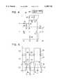
- a printing head 21is provided with a cover plate 201 and a base plate 202 which is provided facing the cover plate 201.
- a part between the cover plate 201 and the base plate 202is formed with piezoelectric material so that partitions are provided by a plurality of shear mode actuator walls 203 polarized in arrow directions F30 and F40 indicated in FIG. 12, and an ink channel 205 and an air channel 212 are arranged alternately between each pair of shear mode actuator walls 203.
- One side of each shear mode actuator wall 203has a film electrode 204, and the other side thereof has a film electrode 214.
- the front end of the shear mode actuator wall 203is provided with a nozzle plate 207 which has nozzles 206 each of which is connected with the ink channel 205, and the rear end of the shear mode actuator wall 203 is provided with a manifold part 209 which has a filler part 208 for preventing intrusion of ink from a common ink passage 213 into the air channel 212.
- the manifold part 209is used for distributing ink from an ink reservoir (not shown) to each ink channel 205.
- Each of the electrodes 204 and 214is covered with an insulating layer (not shown), and the electrode 214 facing the air channel 212 is connected with the ground 211.
- the electrode 204 forming the ink channel 205is connected with a head driver IC (integrated circuit) 83 which applies an actuator drive signal to the electrodes 204 and 214.
- piezoelectric thickness slip deformationoccurs on each shear mode actuator wall 203 to increase a volume of the ink channel 205.
- FIG. 14when a positive drive voltage is applied to the electrode 204 of the ink channel 205, electric fields are produced on the shear mode actuator wall 203 in arrow directions F10 and F20, causing piezoelectric thickness slip deformation to occur on upper walls 203a and lower walls 203b of the shear mode actuator wall 203 so that the volume of the ink channel 205 is increased.
- pressure in the ink channel 205 including a vicinal part of the nozzle 206is decreased. This state is maintained during a period of one-way propagation time T of a pressure wave in the ink channel 205, thereby letting ink be supplied from the common ink passage 213 thereinto.
- the one-way propagation time Tindicates a period of time required for a pressure wave in the ink channel 205 to complete propagation in the longitudinal direction of the ink channel 205.
- pressure in the ink channel 205is reversed to become positive after a lapse of time T following application of the drive voltage.
- the drive voltage being applied to the electrode 204 of the ink channel 205is reset to zero (0) V.
- the shear mode actuator wall 203is restored to normal (FIGS. 12, 13), applying pressure to ink.
- the positive pressureis added to pressure which has been produced by restoration of the shear mode actuator wall 203 to normal, so that relatively high pressure is generated in the vicinity of the nozzle 206 in the ink channel 205, thereby ejecting ink from the ink channel 205 to the outside through the nozzle 206.
- pressure wave oscillationremains in an ink channel even after ink is ejected.
- residual pressure wave oscillationmay cause undesired ink droplets to be sprayed or ejected accidentally through the nozzle 206.
- This unstable ejection of ink dropletsmakes it rather difficult to attain satisfactory quality of printing.
- a print pulse for ink droplet ejectionis followed by a cancel pulse to reduce residual pressure wave oscillation in an ink channel. More specifically, although a pressure wave for ink droplet ejection rebounds from the front and rear ends of the ink channel and a nozzle meniscus is vibrated after a lapse of time 4T following the start of ink droplet ejection, a pressure wave for phase reversal is produced to cancel this phenomenon.
- a further conventional arrangementis disclosed in Japanese Examined Patent Publication No. 6-9920.
- a voltage setup partcomprising four on-off contacts connected in parallel is provided at an interface of a printing head so that one of 16 drive voltage levels can be selected, and one of these contacts is turned on/off according to characteristics of the printing head for the purpose of setting up an optimum drive voltage.
- this arrangementfails to consider variations in the viscosity of ink caused by variations in the ambient temperature.
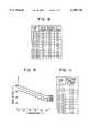
- viscosity of ink used in an ink-jet printing apparatusvaries with ambient temperature as shown in FIG. 15, which shows a relationship between viscosity of ink and ambient temperature thereof.
- the viscosity of inkis approximately 3 mpa.s at an ambient temperature level of 25° C., but it becomes approximately 6 mpa.s at 10° C. and approximately 2 mpa.s at 40° C.
- a volume of ink per dropletstill varies to result in variations in printing quality as shown in FIGS. 16A to 16D.
- FIG. 16Awhen a droplet of ink 293 is ejected through the nozzle 206 formed on the nozzle plate 207 in the same manner as shown in FIGS. 12 and 13, a meniscus 292 protrudes from the nozzle 206 frontward (in ejecting direction) due to positive pressure in residual pressure variation in the ink channel 205. Then, as shown in FIG. 16B, the meniscus 292 retracts from the nozzle 206 backward (toward the ink channel 205) due to negative pressure. In this fashion, the meniscus 292 oscillates, and oscillation thereof ceases after a lapse of a certain period of time.
- the volume of ink per dropletcauses deviation of the ink droplet ejecting direction, resulting in degradation in performance of ink droplet ejection.
- a first drive pulse signalwhen a first drive pulse signal is applied to an actuator for changing a volume of an ink channel which is supplied with ink from an ink reservoir, ink is ejected from the ink channel. Then, a second drive pulse signal which has a wave height equal to that of the first drive pulse signal and a wave width equal to approximately 1.6 to 1.8 times the one-way propagation time T of pressure wave in the ink channel is applied to the actuator at the timing that a center of the second drive pulse signal is provided in a range of approximately 2.25 to 2.75 times the one-way propagation time T from a fall time of the first drive pulse signal.
- driving the actuator by both first and second drive voltagesis limited to a case when a viscosity of ink to be ejected is high and likely to cause vibration of meniscus by a residual pressure in the ink chamber.
- the viscosity of inkis determined by an ambient temperature around the actuator.
- a drive voltage of a drive signal used for setting a predetermined rate of ink droplet ejection from a nozzle of a printing headis regulated in accordance with viscosity of ink to be ejected.
- Ambient temperatureis detected as a parameter of the viscosity of ink.
- the drive voltageis regulated to a lower value as the viscosity of ink becomes higher so that a residual pressure in an ink chamber of the printing head is reduced to suppress vibrations of a meniscus.
- FIG. 1is a schematic perspective view showing an ink-jet printing apparatus according to the first embodiment of the present invention
- FIG. 2is a block diagram showing a control circuit used in the first embodiment shown in FIG. 1;
- FIG. 3Ais a waveform chart of a drive pulse signal used in the first embodiment
- FIG. 3Bis a waveform chart of a drive pulse signal used in the second embodiment
- FIG. 4is an electric wiring diagram of a hear driver circuit used in the first embodiment
- FIG. 5is a time chart showing a relationship between input signals X and Y and waveform of voltage E in the first embodiment
- FIG. 6is a table showing the results of experiment on stability in ink droplet ejection in the first embodiment
- FIG. 7is a table showing the results of measurement of volumes of ejected ink droplets in the first embodiment
- FIG. 8is a table showing a relation between ambient temperature level ranges and drive voltage levels which are classified for each rank of printing head in the third embodiment
- FIG. 9is a graph showing pattern memory data of ambient temperature level ranges and drive voltage levels for each rank of printing head in the third embodiment.
- FIG. 10is a flowchart showing a control procedure to be carried out by a CPU for setting up a proper voltage level in the third embodiment
- FIG. 11is a table showing a relation between ambient temperature and reference voltage levels for regulating the drive voltage to be applied to the printing head in the third embodiment
- FIG. 12is a cross-sectional view of a part of a printing head used in a conventional ink-jet printing apparatus
- FIG. 13is a horizontal cross-sectional view of the printing head shown in FIG. 12;
- FIG. 14is a cross-sectional view showing operation of the ink channel in the printing head shown in FIGS. 12 and 13;
- FIG. 15is a graph showing a relationship between viscosity of ink and ambient temperature.
- FIGS. 16A to 16Dare schematic views showing operation of the printing head in the conventional apparatus.
- an ink-jet printing apparatusis a drop-on-demand ink-jet printing apparatus of a shear mode type using piezoelectric ceramic material as shown in FIGS. 12 and 13.
- a printing apparatus 10is provided with a platen roller 12 which feeds printing paper 11 in a direction from arrow F1 to arrow F2.
- a carriage shaft 13in parallel with the axis thereof, and a carriage 29 having a printing head 20 is supported by the carriage shaft 13.
- a carriage motor 14is equipped at the lower left of the carriage shaft 13, and a pulley 16 is equipped at the lower right of the carriage shaft 13.
- a pulley 15is mounted on a rotor shaft of the carriage motor 14, and an endless belt 17 is hooked between the pulleys 15 and 16.
- the carriage 29is secured on the belt 17. Driven by the carriage motor 14, the carriage 29 slides on the carriage shaft 13 in arrow directions F7 and F8.
- the printing head 20comprises a black-ink head 21 for ejecting black ink, a yellow-ink head 22 for ejecting yellow ink, a cyan-ink head 23 for ejecting cyan ink, and magenta-ink head 24 for ejecting magenta ink.
- a black-ink head 21 for ejecting black inka black-ink head 21 for ejecting black ink
- a yellow-ink head 22for ejecting yellow ink
- a cyan-ink head 23for ejecting cyan ink
- magenta-ink head 24for ejecting magenta ink.
- each of the heads 21 to 24is the same as in the conventional arrangement shown in FIGS. 12 to 14, the description thereof is omitted here.
- an ink absorber pad 30is provided for absorbing ink to be ejected from each of the heads 21 to 24 at the time of flushing operation.
- flushingtwo kinds of operations are performed; post-purge flushing and normal flushing.
- the post-purge flushingis performed for the purpose of discharging unfavorable ink containing air bubbles which may intrude from the nozzle when a suction cap is removed at the time of purging, and the normal flushing is performed at intervals of a predetermined time for the purpose of preventing faulty ejection of ink due to drying-up of ink at each nozzle.
- a purge device 40is provided for removing a possible non-emission or faulty ejection condition from each of the heads 21 to 24.
- the purge device 40comprises a suction cap 41 which is used to cover a nozzle-formed part of each of the heads 21 to 24.
- the suction cap 41is advanced in arrow direction F3 by rotation of a cam 42 so that the nozzle-formed part of each head is covered.
- a pump 43is driven to produce negative pressure, whereby unfavorable ink containing air bubbles in an ink channel of each of the heads 21 to 24 is sucked in succession for recovery of the ink ejecting function of each head.
- a wiper member 50for removing residual ink and any foreign matter which remains on the nozzle-formed part of each of the heads 21 to 24 after the purging operation.
- the wiper member 50is advanced in arrow direction F4 to clean up the nozzle-formed part of each of the heads 21 to 24 to be returned into the printing region.
- a capping device 60for putting each cap 61 on the nozzle-formed part of each of the heads 21 to 24 when the printing head 20 is reset to a home position thereof.
- Each cap 61is advanced in arrow direction F5 when the printing head 20 is reset to the home position, thereby covering the nozzle-formed part of each of the heads 21 to 24.
- a shear mode actuator wall 203 sandwiched between the electrodes 204 and 214is subjected to piezoelectric thickness slip deformation to change pressure in an ink channel 205, thereby ejecting an ink droplet through a nozzle 206 connected with the ink channel 205 to eject ink onto printing paper 11.
- the control circuitcomprises a CPU 70 which issues a printing operation instruction and a flushing instruction to the printing head 20, outputs a purging instruction to the purge device 40 and carries out control of other devices including the above mentioned parts, and a gate array (G/A) 73 which receives printing data from a host computer 71 through an interface (I/F) 72 and carries out control for development of printing data.
- a ROM 74which stores control programs, etc.
- a RAM 75which temporarily stores the printing data received from the host computer 71 by the gate array 73. In this arrangement, necessary data are input/output among these parts.
- the CPU 70is connected with a paper sensor 76 for detecting the presence or absence of printing paper 11, a home position sensor 77 for checking whether the printing head 20 is set at the home position thereof, a temperature sensor 88 for detecting an ambient temperature level in an environment where the printing apparatus 10 is installed, a first motor driver 78 for driving the carriage motor 14, a second motor driver 80 for driving a line feed (LF) motor (not shown) for rotation of the platen roller 12, a control panel 81 for giving various signals to the CPU 70, etc.
- the gate array 73is connected with an image memory 82 in which printing data received from the host computer 71 is temporarily stored as image data.
- the head driver IC 83drives the printing head 20 according to printing data 84, a transfer clock signal 85 and a printing clock signal 86 output from the gate array 73.
- the gate array 73is also connected with an encoder sensor 87 which measures a travel speed of the carriage 29 to determine a time point of printing.
- the CPU 70is further connected to a power regulator circuit 92 which controls a magnitude of a drive voltage applied to the printing head 20 by the head driver IC 83.
- a drive pulse signal 100 supplied to each head from the head driver IC 83comprises a first drive pulse P1 which rises at time T1s and falls at time T1e for ejecting ink and a second drive pulse P2 which rises at time T2s and falls at time T2e for compensating for variation in residual pressure in the ink channel 205 after ink ejection.
- the first drive pulse P1 and second drive pulse P2have the same wave height (magnitude) H.
- a pulse width Wb of the first drive pulse P1corresponds to a one-way propagation time T (L/a) of pressure wave in the ink channel 205.
- Tone-way propagation time
- the ink channel 205is expanded in terms of volume at a rise (start) of the first drive pulse P1 and the ink channel 205 is restored to normal at a fall (end) of the first drive pulse P1, thereby emitting a droplet of ink.
- the pulse width Wbis an odd-numbered multiple of T
- ink droplet ejectionis performed similarly.
- a pulse width Wc of the second drive pulse P2corresponds to a period which is 1.6 to 1.8 times the one-way propagation time T (L/a) of pressure wave in the ink channel 205.
- the second drive pulse P2rises at time T2s so that a center 102 thereof which corresponds to timing T2m is provided in a range of 2.25 to 2.75 times the one-way propagation time T of pressure wave in the ink channel 205 from the fall time T1e of the first drive pulse P1.
- a drive voltage applied to the electrode 204 of the ink channel 205is set to level V or 0 (zero).
- a drive voltageis applied, and when the input signal Y turns on, a drive voltage becomes 0 (zero).
- a capacitor C1is provided by the shear mode actuator wall 203 of the ink channel 205 and a pair of electrodes 204 and 214 formed on both sides thereof.
- the drive circuitcomprises an ejection charge circuit 90 and an ejection discharge circuit 91.
- the input signal Xturns on, it is fed to a base of transistor Q2 through resistor R5 to turn on transistor Q2.
- transistor Q1turns on to apply voltage, e.g., 22 V from a positive power supply 920 to capacitor C1 (voltage E).
- the input signal Yturns on, it is fed to a base of transistor Q3 through resistor R7 to turn on transistor Q3, thereby grounding capacitor C1 (voltage E) through resistor R6.
- FIG. 5there is shown a relationship between timings of the input signals X and Y for the drive pulse signal 100 and waveform of voltage E across capacitor C1.
- the input signal X indicated in a timing chart 93remains off normally.
- the input signal Xturns on (rises) at a predetermined time T1 of ink droplet ejection and it turns off (falls) at a predetermined time T2.
- the input signal Xturns on at a predetermined time T3 and it turns off at a predetermined time T4.
- the input signal Yturns off when the input signal X turns on and it turns on when the input signal X turns off.
- timings T1s, T1e, T2s and T2eare used in correspondence with FIGS. 3A and 3B and a dotted line between 0 and H (e.g., 22V) indicates H/2 (e.g., 11V).
- the voltage Eremains 0 V normally.
- capacitor C1is charged, and voltage E is increased to the height H after a lapse of a charge time Ta which is determined by transistor Q1, resistor R6 and capacitor C1.
- capacitor C1is discharged, and voltage E is decreased to 0 V after a lapse of a discharge time Tb which is determined by transistor Q3, resistor R6 and capacitor C1.
- capacitor C1is charged, and voltage E is decreased to 0 V after a lapse of a discharge time Tb.
- FIG. 6shows the results of ink ejection stability test
- FIG. 7shows the results of measurement of volumes of ejected ink droplets.
- the ink channel 205 of the printing headwas 7.5 mm in length (L).
- the nozzle 206was 35 ⁇ m in diameter on the ink ejection side and 72 ⁇ m in diameter on the ink channel side, and the length of the nozzle 206 was 100 ⁇ m.
- Inkhad viscosity of 3 mpa.s at a temperature of 25° C., and surface tension thereof was 30 mN/m.
- As to variation in viscosity of inkit was 6 mPa.s at a temperature of 10° C. and 2 mpa.s at a temperature of 40° C. as shown in FIG. 15.
- ⁇was given as an indicator of minimum-level variation in ink droplet ejection rate in case that variation in ejection rate was less than 1.0 m/sec. In case that variation in ejection rate was 1.0 to less than 2.0 m/sec., ⁇ O ⁇ was given. In case that variation in ejection rate was 2.0 m/sec. to less than 3.0 m/sec., ⁇ was given. In case that such an irregularity as undesired spraying of ink or undesired ejection of ink droplet was found, ⁇ x ⁇ is given to indicate a condition of faulty ejection.
- the volume of ink per dropletwas 40 pl (target value) or higher when the pulse width Wc of the second drive pulse P2 was in a range of 1.6T to 1.8T. Accordingly, in case that the period ⁇ d ⁇ is 2.3T to 2.7T and the pulse width Wc of the second drive pulse P2 is 1.6T to 1.7T, ejection of ink droplets is most stable and an adequate volume of ink per droplet can be ensured.
- the printing apparatus 10it is possible to realize an ink-jet printing apparatus capable of ensuring a proper volume of ink per droplet for enhancing quality of printing.
- the same arrangement as that of the first embodimentis provided except for a drive pulse signal to be applied to the printing head 20.
- a drive pulse signal 110 shown in FIG. 3Bhas the same wave height (magnitude) H as that of the drive pulse signal 100 indicated in FIG. 3A.
- voltagebecomes H (e.g., 22 V) and, at a fall time of T1e, voltage is decreased to 0 (zero).
- the drive pulse signal 100(FIG. 3A) is used to drive the printing head 20. While the ambient temperature detected by the temperature sensor 88 is less than the predetermined temperature level, the printing head 20 is driven by the drive pulse signal 110 (FIG. 3B).
- the printing head 20is driven by the drive pulse signal 100 when the ambient temperature is higher than the predetermined level, thereby preventing ink droplet ejection from becoming unstable. While the ambient temperature is lower than the predetermined level, the viscosity of ink is relatively high and therefore stable ink droplet ejection can be ensured even if the printing head 20 is driven by the drive pulse signal 110 having no pulse for reducing residual pressure.
- the printing head 20was driven by the drive pulse signal 100 when the ambient temperature of the printing apparatus 10 was higher than 14° C., and the printing head 20 was driven by the drive pulse signal 110 when the ambient temperature was 14° C. or lower.
- the ink droplet ejection ratein the results of experiment, a deviation from the target value of 8 m/s was less than 2.0 m/s, and the volume of ink per droplet was more than 40 pl (target value).
- the number of times a drive voltage is applied to the printing head 20is smaller than that taken in a case where the printing head 20 is driven by the drive pulse signal 100 having two drive pulses, thereby reducing a possible increase in temperature of the head driver IC 83.
- a drive voltage Eis regulated according to variations in the viscosity of ink determined by an ambient temperature Th for the purpose of enhancing ink ejection performance further.
- FIG. 8there is shown a table of ambient temperature level ranges and drive voltage levels which are arranged for each rank of printing head.
- FIG. 9is a graph showing pattern memory data of ambient temperature level ranges and drive voltage levels for each rank of printing head.
- FIG. 10is a flowchart showing a control procedure to be carried out by the CPU 70 for setting up a proper voltage level.
- drive voltage levelsare classified into three ranks A, B and C. That is, since there are variations in manufacture of printing heads, a drive voltage level for attaining a target value of ink droplet ejection rate is different among them, and therefore the printing heads are classified into the three ranks A, B and C according to the drive voltage level. Therefore, the drive voltage necessary for ejecting ink droplets at a target ejection rate (e.g., 8 m/s) in an environment having a constant ambient temperature (e.g., 25° C.) is determined, and then the printing heads are classified as follows: For instance, if the drive voltage is less than 16 V or it is 23 V or more, the printing head is treated as a defective one.
- a target ejection ratee.g. 8 m/s
- an environment having a constant ambient temperaturee.g. 25° C.
- the printing headis classified as rank A. If it is 18 V or more and less than 20 V, the printing head is classified as rank B. If it is 20 V or more and less than 23 V, the printing head is classified as rank C.
- an ambient temperature range from 0° C. to 50° C.is divided in increments of 5° C., and for each divided ambient temperature level range, a drive voltage for attaining a target rate of ink droplet ejection is specified. In this manner, a drive voltage table is mapped and stored in the ROM 74.
- the temperature sensor 88is activated to detect an ambient temperature Th (step 102). Then, it is checked whether the detected ambient temperature Th is 0° C. or higher and lower than 5° C. (step 104). If the detected ambient temperature Th is 0° C. or higher and lower than 5° C., drive voltage data indicating a drive voltage level of 32 V is read from the drive voltage table (FIG. 8) stored in the ROM 74. According to the read-out drive voltage data, a drive voltage change instruction is issued to the power regulator circuit 92 which regulates the voltage of the positive power supply 920 (FIG. 4) so that the drive voltage E is regulated to 32 V (step 105).
- the power regulator circuit 92may be constructed to include an operational amplifier 92a (FIG. 2).
- an operating voltage for the CPU 70is 5 V
- a voltage rangeis divided into ten levels corresponding to ambient temperature ranges detectable by the temperature sensor 88.
- a reference voltage signal having a different voltage value according to variation in ambient temperatureis output from an output port of the CPU 70 to the power supply circuit 92.
- Each voltage value of the reference voltage signalis provided for the operational amplifier 92a used in the power supply circuit 92.
- the reference voltage signal for the A-rank printing headmay be determined as shown in the table of FIG. 11 in correspondence with the detected ambient temperature ranges. It will be understood from a comparison between the tables in FIGS. 8 and 11 that, as the detected ambient temperature increases, the reference voltage to the operational amplifier 92a is increased so that the drive voltage from the power supply 920 is decreased. It is of course possible to decrease the reference voltage with the increase in the detected temperature by modifying the circuit configuration of the power regulator circuit 92.
- the CPU 70is programmed to issue the reference voltages in the table of FIG. 11 at the steps 105, 107, 109, 111, 113, 115, 117, 119, 121 and 123 in FIG. 10 in place of the issuance of the drive voltages E.
- an output voltage of the operational amplifier 92ais changed so that the drive voltage of the power supply 920 is regulated by the power supply circuit 92 to vary between 32 V and 14V.
- Reference voltage tables for B-rank and C-rank printing headsare not exemplified in FIG. 11. Voltage values different from those of reference voltage signals specified in the drive voltage table for the A-rank printing head are may be provided in the drive voltage tables for the B-rank and C-rank printing heads in the similar manner to correspond to the required drive voltages (FIG. 8) for the B-rank and C-rank printing heads.
- the CPU 70may apply the reference signal indicating a particular voltage value from the output port thereof to the power regulator circuit 92, there may be provided such an arrangement that a digital reference signal having a particular bit pattern is output from the output port to the power regulator circuit 92 according to the ambient temperature detected by the temperature sensor 88, the bit pattern of the digital reference signal is read by a D/A converter circuit included in the power regulator circuit 92, and the drive voltage of the power supply 920 is set up according to an output signal from the D/A circuit.
- the printing head 20can be driven by a drive voltage regulated according to characteristics of the printing head 20 and variation in ambient temperature in an installation environment of the printing apparatus 10, i.e., variation in viscosity of ink, thereby making it possible to suppress variation in ink droplet ejection rate, variation in volume of ink per droplet and deviation of ink droplet ejecting direction. More particularly, in comparison with a case where the printing head 20 is driven by a constant drive voltage, the drive voltage is decreased as the viscosity of ink to be ejected becomes higher so that the residual pressure in the ink channel 205 may be reduced to suppress vibration of the meniscus 292 at the nozzle 206. It is therefore possible to further improve stability in ink droplet ejection rate and adequacy in volume of ink per droplet in a wide range of ambient temperature, resulting in still higher quality of printing.
- the positive power supply 920is used.
- a negative power supplymay be used in an arrangement that the shear mode actuator wall 203 is polarized in the directions opposite to arrows F30 and F40 indicated in FIG. 12.
- the upper wall 203a and the lower wall 203b of the shear mode actuator wall 203are deformed by means of piezoelectric thickness slip deformation to change the volume of the ink channel 205 for ejecting ink droplets
- air channel 212is provided on both sides of the ink channel 205 in each of the present preferred embodiments, it is to be understood that ink channels may be arranged adjacently without providing any air channel.
- the printing apparatus 10may comprise a data generating section (host computer) and a printing section (printer) connected therewith, wherein entire control operation for the present invention is carried out by control means including a CPU in the data generating section.
- control meansincluding a CPU in the data generating section.
- a program to be run on the data generating section for the purpose of the control operationmay be made available on such storage media as computer-readable magnetic print media.
Landscapes
- Engineering & Computer Science (AREA)
- Quality & Reliability (AREA)
- Particle Formation And Scattering Control In Inkjet Printers (AREA)
- Ink Jet (AREA)
Abstract
Description
This application relates to and incorporates herein by reference Japanese Patent applications No. 9-95162 filed on Mar. 28, 1997 and No. 9-99757 filed on Apr. 1, 1997.
1. Field of the Invention
The present invention relates to ink-jet printing apparatus for printing by ejecting ink droplets onto print media, and more particularly to an ink-jet printing apparatus which is capable of providing stable performance of ink droplet ejection by driving a printing head thereof with a drive voltage varying with ink viscosity.
2. Description of Related Art
Among conventional ink-jet printing apparatuses, there is a drop-on-demand arrangement of a shear mode type using piezoelectric ceramic material as disclosed in Japanese Unexamined Patent Publication No. 63-247051. A printing head used in this kind of ink-jet printing apparatus is shown in FIGS. 12 and 13.
Referring to FIG. 12, aprinting head 21 is provided with acover plate 201 and abase plate 202 which is provided facing thecover plate 201. A part between thecover plate 201 and thebase plate 202 is formed with piezoelectric material so that partitions are provided by a plurality of shearmode actuator walls 203 polarized in arrow directions F30 and F40 indicated in FIG. 12, and anink channel 205 and anair channel 212 are arranged alternately between each pair of shearmode actuator walls 203. One side of each shearmode actuator wall 203 has afilm electrode 204, and the other side thereof has afilm electrode 214.
As shown in FIG. 13, the front end of the shearmode actuator wall 203 is provided with anozzle plate 207 which hasnozzles 206 each of which is connected with theink channel 205, and the rear end of the shearmode actuator wall 203 is provided with amanifold part 209 which has afiller part 208 for preventing intrusion of ink from acommon ink passage 213 into theair channel 212. Themanifold part 209 is used for distributing ink from an ink reservoir (not shown) to eachink channel 205. Each of theelectrodes electrode 214 facing theair channel 212 is connected with theground 211. Theelectrode 204 forming theink channel 205 is connected with a head driver IC (integrated circuit) 83 which applies an actuator drive signal to theelectrodes
In theprinting head 21 structured as mentioned above, when thehead driver IC 83 applies the actuator drive signal to theelectrode 204, piezoelectric thickness slip deformation occurs on each shearmode actuator wall 203 to increase a volume of theink channel 205. For instance, as shown in FIG. 14, when a positive drive voltage is applied to theelectrode 204 of theink channel 205, electric fields are produced on the shearmode actuator wall 203 in arrow directions F10 and F20, causing piezoelectric thickness slip deformation to occur on upper walls 203a and lower walls 203b of the shearmode actuator wall 203 so that the volume of theink channel 205 is increased. At this step of operation, pressure in theink channel 205 including a vicinal part of thenozzle 206 is decreased. This state is maintained during a period of one-way propagation time T of a pressure wave in theink channel 205, thereby letting ink be supplied from thecommon ink passage 213 thereinto.
The one-way propagation time T indicates a period of time required for a pressure wave in theink channel 205 to complete propagation in the longitudinal direction of theink channel 205. Using length `L` (FIG. 13) of theink channel 205 in the longitudinal direction thereof and acoustic velocity `a` in ink in theink channel 205, `T` is expressed as follows; T=L/a.
Based on the principle of pressure wave propagation, pressure in theink channel 205 is reversed to become positive after a lapse of time T following application of the drive voltage. At the timing of pressure reversal, the drive voltage being applied to theelectrode 204 of theink channel 205 is reset to zero (0) V. Thus, the shearmode actuator wall 203 is restored to normal (FIGS. 12, 13), applying pressure to ink. At this step of operation, the positive pressure is added to pressure which has been produced by restoration of the shearmode actuator wall 203 to normal, so that relatively high pressure is generated in the vicinity of thenozzle 206 in theink channel 205, thereby ejecting ink from theink channel 205 to the outside through thenozzle 206.
In such a conventional ink-jet printing apparatus as mentioned above, pressure wave oscillation remains in an ink channel even after ink is ejected. Particularly, when viscosity of ink is low, residual pressure wave oscillation may cause undesired ink droplets to be sprayed or ejected accidentally through thenozzle 206. This unstable ejection of ink droplets makes it rather difficult to attain satisfactory quality of printing.
In another conventional arrangement, disclosed in Japanese Unexamined Patent Publication No. 62-299343 for example, a print pulse for ink droplet ejection is followed by a cancel pulse to reduce residual pressure wave oscillation in an ink channel. More specifically, although a pressure wave for ink droplet ejection rebounds from the front and rear ends of the ink channel and a nozzle meniscus is vibrated after a lapse of time 4T following the start of ink droplet ejection, a pressure wave for phase reversal is produced to cancel this phenomenon.
However, in such an arrangement that the cancel pulse is generated after a lapse of time 4T following the start of ink droplet ejection, a negative power supply for generating reverse-phase cancel pulses is required in addition to a positive power supply for generating ink emission pulses, causing disadvantages of complexity in an electronic control circuit and an increase in production cost.
A further conventional arrangement is disclosed in Japanese Examined Patent Publication No. 6-9920. In this arrangement, a voltage setup part comprising four on-off contacts connected in parallel is provided at an interface of a printing head so that one of 16 drive voltage levels can be selected, and one of these contacts is turned on/off according to characteristics of the printing head for the purpose of setting up an optimum drive voltage. However, this arrangement fails to consider variations in the viscosity of ink caused by variations in the ambient temperature.
More specifically, viscosity of ink used in an ink-jet printing apparatus varies with ambient temperature as shown in FIG. 15, which shows a relationship between viscosity of ink and ambient temperature thereof. For instance, the viscosity of ink is approximately 3 mpa.s at an ambient temperature level of 25° C., but it becomes approximately 6 mpa.s at 10° C. and approximately 2 mpa.s at 40° C. As the viscosity of ink varies thus, a volume of ink per droplet still varies to result in variations in printing quality as shown in FIGS. 16A to 16D.
That is, as shown in FIG. 16A, when a droplet ofink 293 is ejected through thenozzle 206 formed on thenozzle plate 207 in the same manner as shown in FIGS. 12 and 13, ameniscus 292 protrudes from thenozzle 206 frontward (in ejecting direction) due to positive pressure in residual pressure variation in theink channel 205. Then, as shown in FIG. 16B, themeniscus 292 retracts from thenozzle 206 backward (toward the ink channel 205) due to negative pressure. In this fashion, themeniscus 292 oscillates, and oscillation thereof ceases after a lapse of a certain period of time.
In an experiment, the following phenomena were ascertained. As viscosity of ink decreases, oscillation of themeniscus 292 increases to prolong a period taken until oscillation ceases. Therefore, if the drive voltage is applied to the shear mode actuator to produce pressure in theink channel 205 through piezoelectric thickness slip deformation before oscillation ceases, a rate of ink droplet ejection increases and also a volume of ink per droplet increases.
Since surface tension of themeniscus 292 on an opening plane of thenozzle 206 decreases with a decrease in viscosity of ink, themeniscus 292 droops to hang out to a surface of thenozzle plate 207 as shown in FIG. 16C. In the presence of ahanging part 294 of themeniscus 292, the subsequent droplet ofink 293 is ejected in a deviated direction as shown in FIG. 16D.
As the viscosity of ink decreases to increase the rate of ink droplet ejection, the volume of ink per droplet causes deviation of the ink droplet ejecting direction, resulting in degradation in performance of ink droplet ejection.
It is therefore an object of the present invention to provide an ink-jet printing apparatus which is capable of delivering stable ejection of ink droplets to ensure satisfactory quality of printing and suppressing variation in volume of ink per droplet due to variation in ink viscosity.
According to an aspect of the present invention, when a first drive pulse signal is applied to an actuator for changing a volume of an ink channel which is supplied with ink from an ink reservoir, ink is ejected from the ink channel. Then, a second drive pulse signal which has a wave height equal to that of the first drive pulse signal and a wave width equal to approximately 1.6 to 1.8 times the one-way propagation time T of pressure wave in the ink channel is applied to the actuator at the timing that a center of the second drive pulse signal is provided in a range of approximately 2.25 to 2.75 times the one-way propagation time T from a fall time of the first drive pulse signal. Thus, residual pressure wave oscillation in the ink channel can be suppressed to ensure stable ink droplet ejection, thereby making it possible to attain satisfactory quality of printing. Preferably, driving the actuator by both first and second drive voltages is limited to a case when a viscosity of ink to be ejected is high and likely to cause vibration of meniscus by a residual pressure in the ink chamber. The viscosity of ink is determined by an ambient temperature around the actuator.
According to another aspect of the present invention, a drive voltage of a drive signal used for setting a predetermined rate of ink droplet ejection from a nozzle of a printing head is regulated in accordance with viscosity of ink to be ejected. Ambient temperature is detected as a parameter of the viscosity of ink. Preferably, the drive voltage is regulated to a lower value as the viscosity of ink becomes higher so that a residual pressure in an ink chamber of the printing head is reduced to suppress vibrations of a meniscus.
Other objects, features and advantages of the present invention will be made more apparent from the following detailed description with reference to various embodiments shown in the accompanying drawings. In the drawings:
FIG. 1 is a schematic perspective view showing an ink-jet printing apparatus according to the first embodiment of the present invention;
FIG. 2 is a block diagram showing a control circuit used in the first embodiment shown in FIG. 1;
FIG. 3A is a waveform chart of a drive pulse signal used in the first embodiment, and FIG. 3B is a waveform chart of a drive pulse signal used in the second embodiment;
FIG. 4 is an electric wiring diagram of a hear driver circuit used in the first embodiment;
FIG. 5 is a time chart showing a relationship between input signals X and Y and waveform of voltage E in the first embodiment;
FIG. 6 is a table showing the results of experiment on stability in ink droplet ejection in the first embodiment;
FIG. 7 is a table showing the results of measurement of volumes of ejected ink droplets in the first embodiment;
FIG. 8 is a table showing a relation between ambient temperature level ranges and drive voltage levels which are classified for each rank of printing head in the third embodiment;
FIG. 9 is a graph showing pattern memory data of ambient temperature level ranges and drive voltage levels for each rank of printing head in the third embodiment;
FIG. 10 is a flowchart showing a control procedure to be carried out by a CPU for setting up a proper voltage level in the third embodiment;
FIG. 11 is a table showing a relation between ambient temperature and reference voltage levels for regulating the drive voltage to be applied to the printing head in the third embodiment;
FIG. 12 is a cross-sectional view of a part of a printing head used in a conventional ink-jet printing apparatus;
FIG. 13 is a horizontal cross-sectional view of the printing head shown in FIG. 12;
FIG. 14 is a cross-sectional view showing operation of the ink channel in the printing head shown in FIGS. 12 and 13;
FIG. 15 is a graph showing a relationship between viscosity of ink and ambient temperature; and
FIGS. 16A to 16D are schematic views showing operation of the printing head in the conventional apparatus.
The present invention will now be described in further detail in connection with various embodiments with reference to the accompanying drawings. In the embodiments to follow, an ink-jet printing apparatus is a drop-on-demand ink-jet printing apparatus of a shear mode type using piezoelectric ceramic material as shown in FIGS. 12 and 13.
(First Embodiment)
Referring to FIG. 1, aprinting apparatus 10 is provided with aplaten roller 12 which feedsprinting paper 11 in a direction from arrow F1 to arrow F2. Under theplaten roller 12, there is provided acarriage shaft 13 in parallel with the axis thereof, and acarriage 29 having aprinting head 20 is supported by thecarriage shaft 13. Acarriage motor 14 is equipped at the lower left of thecarriage shaft 13, and apulley 16 is equipped at the lower right of thecarriage shaft 13. Apulley 15 is mounted on a rotor shaft of thecarriage motor 14, and anendless belt 17 is hooked between thepulleys
Thecarriage 29 is secured on thebelt 17. Driven by thecarriage motor 14, thecarriage 29 slides on thecarriage shaft 13 in arrow directions F7 and F8.
Theprinting head 20 comprises a black-ink head 21 for ejecting black ink, a yellow-ink head 22 for ejecting yellow ink, a cyan-ink head 23 for ejecting cyan ink, and magenta-ink head 24 for ejecting magenta ink. At theseheads 21 to 24,ink cartridges 25 to 28 are mounted respectively so that each color ink is supplied to each of theheads 21 to 24.
Since the basic internal structure of each of theheads 21 to 24 is the same as in the conventional arrangement shown in FIGS. 12 to 14, the description thereof is omitted here.
At a predetermined position on the left side of theplaten roller 12, which is an outside region of printing with respect to printingpaper 11, anink absorber pad 30 is provided for absorbing ink to be ejected from each of theheads 21 to 24 at the time of flushing operation. For flushing, two kinds of operations are performed; post-purge flushing and normal flushing. The post-purge flushing is performed for the purpose of discharging unfavorable ink containing air bubbles which may intrude from the nozzle when a suction cap is removed at the time of purging, and the normal flushing is performed at intervals of a predetermined time for the purpose of preventing faulty ejection of ink due to drying-up of ink at each nozzle.
On the right side of theplaten roller 12, which is also an outside region of printing, apurge device 40 is provided for removing a possible non-emission or faulty ejection condition from each of theheads 21 to 24. Thepurge device 40 comprises asuction cap 41 which is used to cover a nozzle-formed part of each of theheads 21 to 24. When each of these heads is set at a purging position, thesuction cap 41 is advanced in arrow direction F3 by rotation of acam 42 so that the nozzle-formed part of each head is covered. Then, apump 43 is driven to produce negative pressure, whereby unfavorable ink containing air bubbles in an ink channel of each of theheads 21 to 24 is sucked in succession for recovery of the ink ejecting function of each head.
On the left side of thesuction cap 41, there is provided awiper member 50 for removing residual ink and any foreign matter which remains on the nozzle-formed part of each of theheads 21 to 24 after the purging operation. Upon completion of purging each head, thewiper member 50 is advanced in arrow direction F4 to clean up the nozzle-formed part of each of theheads 21 to 24 to be returned into the printing region. Thus, residual ink and any foreign matter are removed from the nozzle-formed part to prevent the printing face of printingpaper 11 from being smudged or blotted with ink.
On the right side of thesuction cap 41, there is provided acapping device 60 for putting eachcap 61 on the nozzle-formed part of each of theheads 21 to 24 when theprinting head 20 is reset to a home position thereof. Eachcap 61 is advanced in arrow direction F5 when theprinting head 20 is reset to the home position, thereby covering the nozzle-formed part of each of theheads 21 to 24. Thus, while theprinting apparatus 10 is not in use, ink drying-up is prevented at each of theheads 21 to 24.
In theprinting apparatus 10 configured as shown in FIGS. 12 and 13, when a drive pulse signal is applied toelectrodes head driver IC 83, a shearmode actuator wall 203 sandwiched between theelectrodes ink channel 205, thereby ejecting an ink droplet through anozzle 206 connected with theink channel 205 to eject ink onto printingpaper 11.
Referring to FIG. 2, there is shown a control circuit of theprinting apparatus 10. The control circuit comprises aCPU 70 which issues a printing operation instruction and a flushing instruction to theprinting head 20, outputs a purging instruction to thepurge device 40 and carries out control of other devices including the above mentioned parts, and a gate array (G/A) 73 which receives printing data from ahost computer 71 through an interface (I/F) 72 and carries out control for development of printing data. Between theCPU 70 and thegate array 73, there are provided aROM 74 which stores control programs, etc. and aRAM 75 which temporarily stores the printing data received from thehost computer 71 by thegate array 73. In this arrangement, necessary data are input/output among these parts.
TheCPU 70 is connected with apaper sensor 76 for detecting the presence or absence of printingpaper 11, ahome position sensor 77 for checking whether theprinting head 20 is set at the home position thereof, atemperature sensor 88 for detecting an ambient temperature level in an environment where theprinting apparatus 10 is installed, afirst motor driver 78 for driving thecarriage motor 14, asecond motor driver 80 for driving a line feed (LF) motor (not shown) for rotation of theplaten roller 12, a control panel 81 for giving various signals to theCPU 70, etc. Thegate array 73 is connected with animage memory 82 in which printing data received from thehost computer 71 is temporarily stored as image data. Thehead driver IC 83 drives theprinting head 20 according toprinting data 84, atransfer clock signal 85 and aprinting clock signal 86 output from thegate array 73. Thegate array 73 is also connected with anencoder sensor 87 which measures a travel speed of thecarriage 29 to determine a time point of printing.
TheCPU 70 is further connected to apower regulator circuit 92 which controls a magnitude of a drive voltage applied to theprinting head 20 by thehead driver IC 83.
Referring to FIG. 3A, adrive pulse signal 100 supplied to each head from thehead driver IC 83 comprises a first drive pulse P1 which rises at time T1s and falls at time T1e for ejecting ink and a second drive pulse P2 which rises at time T2s and falls at time T2e for compensating for variation in residual pressure in theink channel 205 after ink ejection. The first drive pulse P1 and second drive pulse P2 have the same wave height (magnitude) H.
A pulse width Wb of the first drive pulse P1 corresponds to a one-way propagation time T (L/a) of pressure wave in theink channel 205. As explained with reference to FIGS. 12 and 13, theink channel 205 is expanded in terms of volume at a rise (start) of the first drive pulse P1 and theink channel 205 is restored to normal at a fall (end) of the first drive pulse P1, thereby emitting a droplet of ink. In case that the pulse width Wb is an odd-numbered multiple of T, ink droplet ejection is performed similarly. A pulse width Wc of the second drive pulse P2 corresponds to a period which is 1.6 to 1.8 times the one-way propagation time T (L/a) of pressure wave in theink channel 205. The second drive pulse P2 rises at time T2s so that acenter 102 thereof which corresponds to timing T2m is provided in a range of 2.25 to 2.75 times the one-way propagation time T of pressure wave in theink channel 205 from the fall time T1e of the first drive pulse P1.
More specifically, in FIG. 3A, the second drive pulse P2 rises to provide condition "d=2.25T to 2.75T". It is to be noted that the second drive pulse P2 is used for suppressing residual pressure wave oscillation in the ink channel caused by the first drive pulse P1, i.e., the second drive pulse P2 is not used for ink droplet ejection. In the present preferred embodiment, a wave height value H of the first drive pulse P1 is. 22 V, a one-way propagation time T is 12 μsec., and a period `d` is 27 to 33 μsec.
Referring to FIG. 4 showing thehead driver IC 83, with input signals X and Y, a drive voltage applied to theelectrode 204 of theink channel 205 is set to level V or 0 (zero). When the input signal X turns on, a drive voltage is applied, and when the input signal Y turns on, a drive voltage becomes 0 (zero). A capacitor C1 is provided by the shearmode actuator wall 203 of theink channel 205 and a pair ofelectrodes
The drive circuit comprises anejection charge circuit 90 and anejection discharge circuit 91. When the input signal X turns on, it is fed to a base of transistor Q2 through resistor R5 to turn on transistor Q2. Then, since a base potential at transistor Q1 decreases when transistor Q2 turns on, transistor Q1 turns on to apply voltage, e.g., 22 V from apositive power supply 920 to capacitor C1 (voltage E). When the input signal Y turns on, it is fed to a base of transistor Q3 through resistor R7 to turn on transistor Q3, thereby grounding capacitor C1 (voltage E) through resistor R6.
Referring to FIG. 5, there is shown a relationship between timings of the input signals X and Y for thedrive pulse signal 100 and waveform of voltage E across capacitor C1.
The input signal X indicated in atiming chart 93 remains off normally. The input signal X turns on (rises) at a predetermined time T1 of ink droplet ejection and it turns off (falls) at a predetermined time T2. Then, the input signal X turns on at a predetermined time T3 and it turns off at a predetermined time T4. As indicated intiming chart 94, the input signal Y turns off when the input signal X turns on and it turns on when the input signal X turns off.
In atiming chart 95 showing an actual waveform of voltage E, timings T1s, T1e, T2s and T2e are used in correspondence with FIGS. 3A and 3B and a dotted line between 0 and H (e.g., 22V) indicates H/2 (e.g., 11V). The voltage E remains 0 V normally. At the predetermined time T1, capacitor C1 is charged, and voltage E is increased to the height H after a lapse of a charge time Ta which is determined by transistor Q1, resistor R6 and capacitor C1. Then, at the predetermined time T2, capacitor C1 is discharged, and voltage E is decreased to 0 V after a lapse of a discharge time Tb which is determined by transistor Q3, resistor R6 and capacitor C1. Thereafter, at the predetermined T3, capacitor C1 is charged, and voltage E is decreased to 0 V after a lapse of a discharge time Tb.
Ink ejection performance in which theprinting head 20 was driven using the drive pulse signal 100 (more specifically as shown in FIG. 5) was analyzed. FIG. 6 shows the results of ink ejection stability test, and FIG. 7 shows the results of measurement of volumes of ejected ink droplets.
In this experiment, theink channel 205 of the printing head was 7.5 mm in length (L). Thenozzle 206 was 35 μm in diameter on the ink ejection side and 72 μm in diameter on the ink channel side, and the length of thenozzle 206 was 100 μm. Ink had viscosity of 3 mpa.s at a temperature of 25° C., and surface tension thereof was 30 mN/m. As to variation in viscosity of ink, it was 6 mPa.s at a temperature of 10° C. and 2 mpa.s at a temperature of 40° C. as shown in FIG. 15. The ratio of acoustic velocity `a` in ink in theink channel 205 to length `L` of theink channel 205 was 12 μsec. (L/a=T).
In our experiment, variations in ink drop ejection rate were measured in continuous operation at a drive frequency of 10 kHz under condition that a drive voltage of thedrive pulse signal 100 was 22 V and an ambient temperature was 40° C. Also, in the experiment, while changing the pulse width Wc of the second drive pulse P2 in a range of 0.5T to 1.9T, a period `d` between the fall time T1e of the first drive pulse P1 and thecenter 102 of the second drive pulse P2 was changed in a range from 2.20 to 2.80. A target value of emission rate was 8 m/sec., and a target value of volume of ink per droplet was 40 pl (picoliters).
In the evaluation, `⊚` was given as an indicator of minimum-level variation in ink droplet ejection rate in case that variation in ejection rate was less than 1.0 m/sec. In case that variation in ejection rate was 1.0 to less than 2.0 m/sec., `O` was given. In case that variation in ejection rate was 2.0 m/sec. to less than 3.0 m/sec., `Δ` was given. In case that such an irregularity as undesired spraying of ink or undesired ejection of ink droplet was found, `x` is given to indicate a condition of faulty ejection.
As understood from the experimental results shown in FIG. 6, variation in ink droplet ejection rate was minimized under condition that the period `d` was 2.3T, 2.5T and 2.7T and the pulse width Wc of the second drive pulse P2 is 0.5T and 1.3T to 1.7T.
Then, in measurement of volumes of ejected ink droplets, a period of 2.5T was selected as a representative of the three values `d` indicated above, and the pulse width Wc of the second drive pulse P2 was changed in a range of 0.5T to 1.8T.
As understood from FIG. 7, the volume of ink per droplet was 40 pl (target value) or higher when the pulse width Wc of the second drive pulse P2 was in a range of 1.6T to 1.8T. Accordingly, in case that the period `d` is 2.3T to 2.7T and the pulse width Wc of the second drive pulse P2 is 1.6T to 1.7T, ejection of ink droplets is most stable and an adequate volume of ink per droplet can be ensured.
On the assumption that satisfactory quality of printing can be maintained in case that variation in ink droplet ejection rate is in a range of 1.0 to 2.0 m/s, this allowable range can be attained even in case that the period `d` is 2.25T or 2.75T and the pulse width Wc is 0.5T to 1.8T as shown by `O` in FIG. 6.
It is therefore apparent that both the requirements of stable ejection of ink droplets and proper volume of ink per droplet can be satisfied where the pulse width Wc of the second drive pulse P2 is 1.6T to 1.8T and the period `d` between the fall time of the first drive pulse P1 and thecenter 102 of the second drive pulse P2 is 2.25T to 2.75T.
As described above, according to the first preferred embodiment of theprinting apparatus 10, it is possible to realize an ink-jet printing apparatus capable of ensuring a proper volume of ink per droplet for enhancing quality of printing.
(Second Embodiment)
In the second embodiment, the same arrangement as that of the first embodiment is provided except for a drive pulse signal to be applied to theprinting head 20.
Adrive pulse signal 110 shown in FIG. 3B has the same wave height (magnitude) H as that of thedrive pulse signal 100 indicated in FIG. 3A. At a rise time T1s, voltage becomes H (e.g., 22 V) and, at a fall time of T1e, voltage is decreased to 0 (zero). A pulse width Wa of thedrive pulse signal 110 is equal to the pulse width Wb of first drive pulse P1 of thedrive pulse signal 100, i.e., Wa=T.
When the ambient temperature detected by thetemperature sensor 88 exceeds a predetermined temperature level, the drive pulse signal 100 (FIG. 3A) is used to drive theprinting head 20. While the ambient temperature detected by thetemperature sensor 88 is less than the predetermined temperature level, theprinting head 20 is driven by the drive pulse signal 110 (FIG. 3B).
More specifically, since the viscosity of ink used for printing decreases with an increase in ambient temperature as shown in FIG. 15, theprinting head 20 is driven by thedrive pulse signal 100 when the ambient temperature is higher than the predetermined level, thereby preventing ink droplet ejection from becoming unstable. While the ambient temperature is lower than the predetermined level, the viscosity of ink is relatively high and therefore stable ink droplet ejection can be ensured even if theprinting head 20 is driven by thedrive pulse signal 110 having no pulse for reducing residual pressure.
In the experiment, theprinting head 20 was driven by thedrive pulse signal 100 when the ambient temperature of theprinting apparatus 10 was higher than 14° C., and theprinting head 20 was driven by thedrive pulse signal 110 when the ambient temperature was 14° C. or lower. As to the ink droplet ejection rate in the results of experiment, a deviation from the target value of 8 m/s was less than 2.0 m/s, and the volume of ink per droplet was more than 40 pl (target value).
As described above, in the second preferred embodiment of theprinting apparatus 10, either thedrive pulse signal 100 or thedrive pulse signal 110 is selected according to an ambient temperature in an environment in which theprinting apparatus 10 is installed, thereby making it possible to ensure stability in ink droplet ejection rate and adequacy in volume of ink per droplet.
Still more, at a low ambient temperature of less than 14° C. for example, since theprinting head 20 is driven by thedrive pulse signal 110 having just one drive pulse, the number of times a drive voltage is applied to theprinting head 20 is smaller than that taken in a case where theprinting head 20 is driven by thedrive pulse signal 100 having two drive pulses, thereby reducing a possible increase in temperature of thehead driver IC 83.
(Third Embodiment)
In the third embodiment, a drive voltage E is regulated according to variations in the viscosity of ink determined by an ambient temperature Th for the purpose of enhancing ink ejection performance further.
Referring to FIG. 8, there is shown a table of ambient temperature level ranges and drive voltage levels which are arranged for each rank of printing head. FIG. 9 is a graph showing pattern memory data of ambient temperature level ranges and drive voltage levels for each rank of printing head. FIG. 10 is a flowchart showing a control procedure to be carried out by theCPU 70 for setting up a proper voltage level.
As shown in FIG. 8, drive voltage levels are classified into three ranks A, B and C. That is, since there are variations in manufacture of printing heads, a drive voltage level for attaining a target value of ink droplet ejection rate is different among them, and therefore the printing heads are classified into the three ranks A, B and C according to the drive voltage level. Therefore, the drive voltage necessary for ejecting ink droplets at a target ejection rate (e.g., 8 m/s) in an environment having a constant ambient temperature (e.g., 25° C.) is determined, and then the printing heads are classified as follows: For instance, if the drive voltage is less than 16 V or it is 23 V or more, the printing head is treated as a defective one. If the drive voltage is 16 V or more and less than 18 V, the printing head is classified as rank A. If it is 18 V or more and less than 20 V, the printing head is classified as rank B. If it is 20 V or more and less than 23 V, the printing head is classified as rank C.
Further, an ambient temperature range from 0° C. to 50° C. is divided in increments of 5° C., and for each divided ambient temperature level range, a drive voltage for attaining a target rate of ink droplet ejection is specified. In this manner, a drive voltage table is mapped and stored in theROM 74.
As a representative example, the drive voltage control procedure for an A-rank printing head, selected from three ranks, is described below.
First, when power to theprinting apparatus 10 is turned on (step 100), thetemperature sensor 88 is activated to detect an ambient temperature Th (step 102). Then, it is checked whether the detected ambient temperature Th is 0° C. or higher and lower than 5° C. (step 104). If the detected ambient temperature Th is 0° C. or higher and lower than 5° C., drive voltage data indicating a drive voltage level of 32 V is read from the drive voltage table (FIG. 8) stored in theROM 74. According to the read-out drive voltage data, a drive voltage change instruction is issued to thepower regulator circuit 92 which regulates the voltage of the positive power supply 920 (FIG. 4) so that the drive voltage E is regulated to 32 V (step 105).
If the detected ambient temperature Th is 5° C. or higher, determination is repeated until the detected temperature level range is reached in one of the followingsteps steps ROM 74. According to the read-out drive voltage data, a proper drive voltage is set up in thepositive power supply 920.
In implementing the third embodiment, thepower regulator circuit 92 may be constructed to include anoperational amplifier 92a (FIG. 2). In case that an operating voltage for theCPU 70 is 5 V, a voltage range is divided into ten levels corresponding to ambient temperature ranges detectable by thetemperature sensor 88. In this arrangement, a reference voltage signal having a different voltage value according to variation in ambient temperature is output from an output port of theCPU 70 to thepower supply circuit 92.
Each voltage value of the reference voltage signal is provided for theoperational amplifier 92a used in thepower supply circuit 92. The reference voltage signal for the A-rank printing head may be determined as shown in the table of FIG. 11 in correspondence with the detected ambient temperature ranges. It will be understood from a comparison between the tables in FIGS. 8 and 11 that, as the detected ambient temperature increases, the reference voltage to theoperational amplifier 92a is increased so that the drive voltage from thepower supply 920 is decreased. It is of course possible to decrease the reference voltage with the increase in the detected temperature by modifying the circuit configuration of thepower regulator circuit 92.
In this implementation, theCPU 70 is programmed to issue the reference voltages in the table of FIG. 11 at thesteps operational amplifier 92a is changed so that the drive voltage of thepower supply 920 is regulated by thepower supply circuit 92 to vary between 32 V and 14V.
Reference voltage tables for B-rank and C-rank printing heads are not exemplified in FIG. 11. Voltage values different from those of reference voltage signals specified in the drive voltage table for the A-rank printing head are may be provided in the drive voltage tables for the B-rank and C-rank printing heads in the similar manner to correspond to the required drive voltages (FIG. 8) for the B-rank and C-rank printing heads.
In order for theCPU 70 to apply the reference signal indicating a particular voltage value from the output port thereof to thepower regulator circuit 92, there may be provided such an arrangement that a digital reference signal having a particular bit pattern is output from the output port to thepower regulator circuit 92 according to the ambient temperature detected by thetemperature sensor 88, the bit pattern of the digital reference signal is read by a D/A converter circuit included in thepower regulator circuit 92, and the drive voltage of thepower supply 920 is set up according to an output signal from the D/A circuit.
As described above, in the third embodiment of theprinting apparatus 10, theprinting head 20 can be driven by a drive voltage regulated according to characteristics of theprinting head 20 and variation in ambient temperature in an installation environment of theprinting apparatus 10, i.e., variation in viscosity of ink, thereby making it possible to suppress variation in ink droplet ejection rate, variation in volume of ink per droplet and deviation of ink droplet ejecting direction. More particularly, in comparison with a case where theprinting head 20 is driven by a constant drive voltage, the drive voltage is decreased as the viscosity of ink to be ejected becomes higher so that the residual pressure in theink channel 205 may be reduced to suppress vibration of themeniscus 292 at thenozzle 206. It is therefore possible to further improve stability in ink droplet ejection rate and adequacy in volume of ink per droplet in a wide range of ambient temperature, resulting in still higher quality of printing.
(Other Embodiments)
In each of the above preferred embodiments, thepositive power supply 920 is used. Instead, a negative power supply may be used in an arrangement that the shearmode actuator wall 203 is polarized in the directions opposite to arrows F30 and F40 indicated in FIG. 12. Also, while the upper wall 203a and the lower wall 203b of the shearmode actuator wall 203 are deformed by means of piezoelectric thickness slip deformation to change the volume of theink channel 205 for ejecting ink droplets, it is possible to provide an arrangement that one of the upper wall 203a and the lower wall 203b is made of any material not allowing piezoelectric thickness slip deformation and the other wall allowing piezoelectric thickness slip deformation is deformed to change the volume of theink channel 205 for emitting ink droplets.
Still more, while theair channel 212 is provided on both sides of theink channel 205 in each of the present preferred embodiments, it is to be understood that ink channels may be arranged adjacently without providing any air channel.
Still more, it is to be understood that theprinting apparatus 10 may comprise a data generating section (host computer) and a printing section (printer) connected therewith, wherein entire control operation for the present invention is carried out by control means including a CPU in the data generating section. In this arrangement, a program to be run on the data generating section for the purpose of the control operation may be made available on such storage media as computer-readable magnetic print media.
The present invention should not be limited to the disclosed embodiments but may be implemented in various ways without departing from the spirit of the invention.
Claims (19)
1. An ink-jet printing apparatus comprising:
a printing head having an ink channel, an actuator for changing a volume of the ink channel and a nozzle connected with the ink channel to eject the ink from the ink channel onto a print media; and
a drive circuit connected to the printing head for applying a first drive pulse signal to the actuator so that the ink channel is expanded a volume thereof to generate a pressure wave in the ink channel and, after a lapse of an approximate odd-numbered multiple of one-way propagation time T of the pressure wave in the ink channel, an expanded volume of the ink channel is decreased to normal state thereof to apply pressure to the ink in the ink channel for ejecting the ink from the ink channel through the nozzle,
wherein the drive circuit, after applying the first drive pulse signal to the actuator, applies to the actuator a second drive pulse signal which has a center thereof in a range of approximately 2.25 to 2.75 times the one-way propagation time T from an end time of the first drive pulse signal.
2. An ink-jet printing apparatus comprising:
a printing head having an ink channel, an actuator for changing a volume of the ink channel and a nozzle connected with the ink channel to eject the ink from the ink channel onto a print media; and
a drive circuit connected to the printing head for applying a first drive pulse signal to the actuator so that the ink channel is expanded a volume thereof to generate a pressure wave in the ink channel and, after a lapse of an approximate odd-numbered multiple of one-way propagation time T of the pressure wave in the ink channel, an expanded volume of the ink channel is decreased to normal state thereof to apply pressure to the ink in the ink channel for ejecting the ink from the ink channel through the nozzle,
wherein the drive circuit, after applying the first drive pulse signal to the actuator, applies to the actuator a second drive pulse signal which has a magnitude substantially equal to that of the first drive pulse signal and a pulse width equal to approximately 1.6 to 1.8 times the one-way propagation time T so that a center of the second drive pulse signal is provided in a range of approximately 2.25 to 2.75 times the one-way propagation time T from an end time of the first drive pulse signal.
3. The ink-jet printing apparatus according to claim 2, further comprising:
a detecting device connected to the drive circuit for detecting a parameter indicative of a viscosity of the ink,
wherein the drive circuit restricts the second drive pulse signal from being applied to the actuator when the detected parameter is indicative of the viscosity being lower than a predetermined level.
4. The ink-jet printing apparatus according to claim 3, wherein the detecting device includes an ambient temperature sensor for detecting an ambient temperature around the printing head.
5. The ink-jet printing apparatus according to claim 3, wherein the drive circuit includes a regulator operatively connected to the detecting device for regulating voltages of the first and second drive pulse signals according to the detected parameter.
6. The ink-jet printing apparatus according to claim 5, wherein the regulator is constructed to decrease the voltages as the viscosity of the ink indicated by the detected parameter decreases.
7. The ink-jet printing apparatus according to claim 6, wherein the regulator is constructed to change the voltages in accordance with a voltage required by the printing head to eject the ink at a predetermined speed.
8. The ink-jet printing apparatus according to claim 2, wherein the actuator includes at least one wall part defining the ink channel and at least one area of the wall part is formed by a piezoelectric material.
9. The ink-jet printing apparatus according to claim 2, wherein the center of the second drive pulse signal is provided in a range of approximately 2.30 to 2.70 times the one-way propagation time T from the end time of the first drive pulse signal.
10. The ink-jet printing apparatus according to claim 2, wherein the pulse width of the second drive pulse signal is approximately 1.6 to 1.7 times the one-way propagation time T.
11. The ink-jet printing apparatus according to claim 2, wherein the pulse width of the second drive pulse signal is approximately 1.6 to 1.7 times the one-way propagation time T and the center of the second drive pulse signal is provided in a range of approximately 2.30 to 2.70 times the one-way propagation time T from the end time of the first drive pulse signal.
12. An ink-jet printing apparatus comprising:
a printing head including an ink channel, an actuator driven by a drive signal for changing pressure in the ink channel and a nozzle connected with the ink channel so that ink is ejected from the ink channel onto print media by changes in pressure in the ink channel;
temperature detecting device for detecting an ambient temperature around the printer head; and
a drive circuit connected between the temperature detecting device and the actuator for applying the drive signal to the actuator, the drive circuit including a reference voltage setting part for setting a drive voltage of the drive signal according to printing head characteristics and the detected ambient temperature so that a rate of ink droplet ejection from the nozzle is adjusted to a predetermined ink droplet ejection rate, wherein the reference voltage setting part has a data table defining a relationship of the drive voltage relative to the printing head characteristics and the ambient temperature so that the drive voltage is set with reference to the data table.
13. The ink-jet printing apparatus according to claim 12, wherein the reference voltage setting part decreases the drive voltage as the detected ambient temperature becomes higher.
14. The ink-jet printing apparatus according to claim 12, wherein the reference voltage setting part regulates the drive voltage to any one of plural predetermined drive voltage levels in response to the detected ambient temperature.
15. The ink-jet printing apparatus according to claim 12, wherein the reference voltage setting part is provided with a plurality of data patterns of printing head characteristics for drive voltage levels corresponding to temperature level ranges detectable by the temperature detecting device and sets the drive voltage in response to the detected ambient temperature.
16. An ink-jet printing apparatus comprising:
a printing head including an ink channel, an actuator driven by a drive signal for changing pressure in the ink channel and a nozzle connected with the ink channel so that ink is ejected from the ink channel onto print media by changes in pressure in the ink channel;
detecting circuit for detecting a parameter variable with a viscosity of the ink to be ejected;
a memory defined in a form of a data table which defines a relationship of a drive voltage of the drive signal relative to the operation characteristics of the printing head and the parameter; and
a drive circuit for applying the drive signal to the actuator, the drive circuit being for variably setting the drive voltage of the drive signal in dependence on the detected parameter and the operation characteristics with reference to the data table in the memory.
17. The ink-jet printing apparatus according to claim 16, wherein the drive voltage is decreased as the detected parameter indicates an increase in the viscosity of the ink.
18. The ink-jet printing apparatus according to claim 17, wherein the drive voltage is further decreased as the operation characteristics of the printing head is ranked as requiring a lower voltage for ejecting the ink at a predetermined speed.
19. The ink-jet printing apparatus according to claim 16, wherein the detecting device detects an ambient temperature around the printing head and the drive voltage is decreased as the detected ambient temperature becomes higher.
Applications Claiming Priority (4)
| Application Number | Priority Date | Filing Date | Title |
|---|---|---|---|
| JP9516297AJPH10272766A (en) | 1997-03-28 | 1997-03-28 | Ink jet recording device |
| JP9-095162 | 1997-03-28 | ||
| JP9975797AJPH10278269A (en) | 1997-04-01 | 1997-04-01 | Ink jet recording device |
| JP9-099757 | 1997-04-01 |
Publications (1)
| Publication Number | Publication Date |
|---|---|
| US6109716Atrue US6109716A (en) | 2000-08-29 |
Family
ID=26436438
Family Applications (1)
| Application Number | Title | Priority Date | Filing Date |
|---|---|---|---|
| US09/037,086Expired - LifetimeUS6109716A (en) | 1997-03-28 | 1998-03-09 | Ink-jet printing apparatus having printed head driven by ink viscosity dependent drive pulse |
Country Status (1)
| Country | Link |
|---|---|
| US (1) | US6109716A (en) |
Cited By (41)
| Publication number | Priority date | Publication date | Assignee | Title |
|---|---|---|---|---|
| US6257686B1 (en)* | 1997-12-16 | 2001-07-10 | Brother Kogyo Kabushiki Kaisha | Ink droplet ejecting method and apparatus |
| US6260959B1 (en)* | 1998-05-20 | 2001-07-17 | Brother Kogyo Kabushiki Kaisha | Ink ejector |
| US6398331B1 (en)* | 1999-02-09 | 2002-06-04 | Oki Data Corporation | Apparatus for driving a printhead and method of driving the printhead |
| US6467865B1 (en)* | 1998-07-29 | 2002-10-22 | Fuji Xerox Co., Ltd. | Ink jet recording head and ink jet recorder |
| US6471320B2 (en) | 2001-03-09 | 2002-10-29 | Hewlett-Packard Company | Data bandwidth reduction to printhead with redundant nozzles |
| US6478396B1 (en) | 2001-03-02 | 2002-11-12 | Hewlett-Packard Company | Programmable nozzle firing order for printhead assembly |
| US6543879B1 (en) | 2001-10-31 | 2003-04-08 | Hewlett-Packard Company | Inkjet printhead assembly having very high nozzle packing density |
| US6575544B2 (en)* | 2001-01-30 | 2003-06-10 | Brother Kogyo Kabushiki Kaisha | Optimizing driving pulses period to prevent the occurrence of satellite droplets |
| US6585339B2 (en) | 2001-01-05 | 2003-07-01 | Hewlett Packard Co | Module manager for wide-array inkjet printhead assembly |
| US20030142346A1 (en)* | 2001-11-22 | 2003-07-31 | Seiko Epson Corporation | IC chip, print apparatus, and heat generation warning method |
| US6604802B2 (en)* | 2000-06-20 | 2003-08-12 | Matsushita Electric Industrial Co., Ltd. | Inkjet head and inkjet recording apparatus |
| US20040001121A1 (en)* | 2002-06-12 | 2004-01-01 | Takeshi Kameda | Inkjet printhead and inkjet image apparatus |
| US20040017413A1 (en)* | 2002-06-28 | 2004-01-29 | Ryutaro Kusunoki | Apparatus for driving ink jet head |
| US6685289B2 (en) | 2001-02-08 | 2004-02-03 | Hewlett-Packard Development Company, L.P. | Low voltage differential signaling for communicating with inkjet printhead assembly |
| US6705694B1 (en)* | 1999-02-19 | 2004-03-16 | Hewlett-Packard Development Company, Lp. | High performance printing system and protocol |
| US20040051759A1 (en)* | 1998-10-16 | 2004-03-18 | Kia Silverbrook | Operating a page width printhead to print an image |
| US6726300B2 (en) | 2002-04-29 | 2004-04-27 | Hewlett-Packard Development Company, L.P. | Fire pulses in a fluid ejection device |
| US6729707B2 (en) | 2002-04-30 | 2004-05-04 | Hewlett-Packard Development Company, L.P. | Self-calibration of power delivery control to firing resistors |
| US6746107B2 (en) | 2001-10-31 | 2004-06-08 | Hewlett-Packard Development Company, L.P. | Inkjet printhead having ink feed channels defined by thin-film structure and orifice layer |
| US6755495B2 (en) | 2001-03-15 | 2004-06-29 | Hewlett-Packard Development Company, L.P. | Integrated control of power delivery to firing resistors for printhead assembly |
| US20040141019A1 (en)* | 2001-01-05 | 2004-07-22 | Schloeman Dennis J. | Integrated programmable fire pulse generator for inkjet printhead assembly |
| US20040155915A1 (en)* | 2003-02-12 | 2004-08-12 | Konica Minolta Holdings, Inc. | Droplet ejection apparatus and its drive method |
| US20050018003A1 (en)* | 2003-07-25 | 2005-01-27 | Toshiba Tec Kabushiki Kaisha | Ink-jet head driving method and ink-jet recording apparatus |
| US6932453B2 (en) | 2001-10-31 | 2005-08-23 | Hewlett-Packard Development Company, L.P. | Inkjet printhead assembly having very high drop rate generation |
| US20060038839A1 (en)* | 2004-08-18 | 2006-02-23 | Jung-Hwa Lee | Method of determining a driving signal of an ink-jet printer head using an image forming device |
| US20060061624A1 (en)* | 2004-09-22 | 2006-03-23 | Fuji Photo Film Co., Ltd. | Liquid ejection apparatus and liquid ejection head restoring method |
| US20060166372A1 (en)* | 2003-01-23 | 2006-07-27 | Hartwig Preckel | Method for fillling sample carriers |
| US7083249B2 (en)* | 2000-09-29 | 2006-08-01 | Brother Kogyo Kabushiki Kaisha | Method for establishing standard values to obscure banding in printed result of ink jet printer and ink jet printer set up by the same |
| US20060214538A1 (en)* | 2005-03-25 | 2006-09-28 | Masakazu Okuda | Driving method of liquid drop ejecting head and liquid drop ejecting apparatus |
| US20060221112A1 (en)* | 2005-03-30 | 2006-10-05 | Brother Kogyo Kabushiki Kaisha | Ink-jet recording apparatus |
| US20070242095A1 (en)* | 2005-04-04 | 2007-10-18 | Silverbrook Research Pty Ltd | Inkjet Printhead That Prints Keep-Wet Dots To Avoid Clogging |
| US20080136861A1 (en)* | 2006-12-11 | 2008-06-12 | 3M Innovative Properties Company | Method and apparatus for printing conductive inks |
| US20110122183A1 (en)* | 2005-04-04 | 2011-05-26 | Silverbrook Research Pty Ltd | Printhead incorporating pressure pulse diffusing structures between ink chambers supplied by same ink inlet |
| US8047633B2 (en) | 1998-10-16 | 2011-11-01 | Silverbrook Research Pty Ltd | Control of a nozzle of an inkjet printhead |
| CN103171282A (en)* | 2011-12-26 | 2013-06-26 | 精工爱普生株式会社 | Liquid ejecting apparatus and control method of liquid ejecting head |
| US8531692B2 (en)* | 2006-12-08 | 2013-09-10 | Samsung Electronics Co., Ltd. | Method and apparatus to generate color conversion profiles |
| US20150070423A1 (en)* | 2013-09-06 | 2015-03-12 | Kabushiki Kaisha Toshiba | Inkjet head, driving device of inkjet head and driving method thereof |
| US9073373B2 (en) | 2011-08-02 | 2015-07-07 | Seiko Epson Corporation | Control method of and control device for controlling liquid ejection head, and liquid ejecting apparatus |
| US9469098B2 (en) | 2011-09-21 | 2016-10-18 | Memjet Technology Limited | Method of inkjet printing and maintaining nozzle hydration |
| EP3335880A1 (en)* | 2016-12-13 | 2018-06-20 | SII Printek Inc | Liquid jet head and liquid jet head drive method |
| US10535810B2 (en)* | 2016-03-30 | 2020-01-14 | Jtekt Corporation | Control apparatus and fluid feeder control method |
Citations (10)
| Publication number | Priority date | Publication date | Assignee | Title |
|---|---|---|---|---|
| US4352114A (en)* | 1979-10-23 | 1982-09-28 | Canon Kabushiki Kaisha | Ink jet printer with temperature compensation |
| JPS61197247A (en)* | 1985-02-28 | 1986-09-01 | Canon Inc | Ink jet recording device |
| JPS62299343A (en)* | 1986-06-20 | 1987-12-26 | Canon Inc | Ink jet recording apparatus |
| JPS63247051A (en)* | 1987-01-10 | 1988-10-13 | ザール リミテッド | Pulse droplet bonder and manufacture of pulse droplet bonder |
| US4947194A (en)* | 1986-11-06 | 1990-08-07 | Canon Kabushiki Kaisha | Liquid injection recording apparatus having temperature detecting means in a liquid passage |
| US4980699A (en)* | 1986-12-17 | 1990-12-25 | Canon Kabushiki Kaisha | Liquid injection recording method for accurately producing an image regardless of ambient temperature |
| US5264865A (en)* | 1986-12-17 | 1993-11-23 | Canon Kabushiki Kaisha | Ink jet recording method and apparatus utilizing temperature dependent, pre-discharge, meniscus retraction |
| JPH069920A (en)* | 1992-06-24 | 1994-01-18 | Kansai Paint Co Ltd | Water-base coating resin composition |
| US5774137A (en)* | 1995-12-09 | 1998-06-30 | Brother Kogyo Kabushiki Kaisha | Ink jet printer |
| US5909228A (en)* | 1995-08-09 | 1999-06-01 | Brother Kogyo Kabushiki Kaisha | Ink-jet device having phase shifted driving signals and a driving method thereof |
- 1998
- 1998-03-09USUS09/037,086patent/US6109716A/ennot_activeExpired - Lifetime
Patent Citations (11)
| Publication number | Priority date | Publication date | Assignee | Title |
|---|---|---|---|---|
| US4352114A (en)* | 1979-10-23 | 1982-09-28 | Canon Kabushiki Kaisha | Ink jet printer with temperature compensation |
| JPS61197247A (en)* | 1985-02-28 | 1986-09-01 | Canon Inc | Ink jet recording device |
| JPS62299343A (en)* | 1986-06-20 | 1987-12-26 | Canon Inc | Ink jet recording apparatus |
| US4972211A (en)* | 1986-06-20 | 1990-11-20 | Canon Kabushiki Kaisha | Ink jet recorder with attenuation of meniscus vibration in a ejection nozzle thereof |
| US4947194A (en)* | 1986-11-06 | 1990-08-07 | Canon Kabushiki Kaisha | Liquid injection recording apparatus having temperature detecting means in a liquid passage |
| US4980699A (en)* | 1986-12-17 | 1990-12-25 | Canon Kabushiki Kaisha | Liquid injection recording method for accurately producing an image regardless of ambient temperature |
| US5264865A (en)* | 1986-12-17 | 1993-11-23 | Canon Kabushiki Kaisha | Ink jet recording method and apparatus utilizing temperature dependent, pre-discharge, meniscus retraction |
| JPS63247051A (en)* | 1987-01-10 | 1988-10-13 | ザール リミテッド | Pulse droplet bonder and manufacture of pulse droplet bonder |
| JPH069920A (en)* | 1992-06-24 | 1994-01-18 | Kansai Paint Co Ltd | Water-base coating resin composition |
| US5909228A (en)* | 1995-08-09 | 1999-06-01 | Brother Kogyo Kabushiki Kaisha | Ink-jet device having phase shifted driving signals and a driving method thereof |
| US5774137A (en)* | 1995-12-09 | 1998-06-30 | Brother Kogyo Kabushiki Kaisha | Ink jet printer |
Cited By (93)
| Publication number | Priority date | Publication date | Assignee | Title |
|---|---|---|---|---|
| US7597435B2 (en) | 1997-07-15 | 2009-10-06 | Silverbrook Research Pty Ltd | Ink supply unit for an ink jet printer |
| US20080129809A1 (en)* | 1997-07-15 | 2008-06-05 | Silverbrook Research Pty Ltd | Ink Supply Unit For An Ink Jet Printer |
| US6257686B1 (en)* | 1997-12-16 | 2001-07-10 | Brother Kogyo Kabushiki Kaisha | Ink droplet ejecting method and apparatus |
| US6260959B1 (en)* | 1998-05-20 | 2001-07-17 | Brother Kogyo Kabushiki Kaisha | Ink ejector |
| US6467865B1 (en)* | 1998-07-29 | 2002-10-22 | Fuji Xerox Co., Ltd. | Ink jet recording head and ink jet recorder |
| US20070182784A1 (en)* | 1998-10-16 | 2007-08-09 | Silverbrook Research Pty Ltd | Ink ejection nozzle arrangement with layered actuator mechanism |
| US8047633B2 (en) | 1998-10-16 | 2011-11-01 | Silverbrook Research Pty Ltd | Control of a nozzle of an inkjet printhead |
| US8087757B2 (en) | 1998-10-16 | 2012-01-03 | Silverbrook Research Pty Ltd | Energy control of a nozzle of an inkjet printhead |
| US6938994B2 (en) | 1998-10-16 | 2005-09-06 | Silverbrook Research Pty Ltd | Method of operating an ink jet printhead within a predetermined temperature range |
| US20090309909A1 (en)* | 1998-10-16 | 2009-12-17 | Silverbrook Research Pty Ltd | Nozzle arrangement with fully static cmos control logic architecture |
| US8066355B2 (en) | 1998-10-16 | 2011-11-29 | Silverbrook Research Pty Ltd | Compact nozzle assembly of an inkjet printhead |
| US7152944B2 (en) | 1998-10-16 | 2006-12-26 | Silverbrook Research Pty Ltd | Ink jet printhead assembly with an ink distribution manifold |
| US20090303297A1 (en)* | 1998-10-16 | 2009-12-10 | Silverbrook Research Pty Ltd. | Ink Supply Unit For Ink Jet Printer |
| US7971972B2 (en) | 1998-10-16 | 2011-07-05 | Silverbrook Research Pty Ltd | Nozzle arrangement with fully static CMOS control logic architecture |
| US20070030321A1 (en)* | 1998-10-16 | 2007-02-08 | Silverbrook Research Pty Ltd | Ink supply unit for an ink jet printer |
| US20050146566A1 (en)* | 1998-10-16 | 2005-07-07 | Kia Silverbrook | Inkjet printhead that incorporates feed back sense lines |
| US20040051759A1 (en)* | 1998-10-16 | 2004-03-18 | Kia Silverbrook | Operating a page width printhead to print an image |
| US8061795B2 (en) | 1998-10-16 | 2011-11-22 | Silverbrook Research Pty Ltd | Nozzle assembly of an inkjet printhead |
| US8057014B2 (en) | 1998-10-16 | 2011-11-15 | Silverbrook Research Pty Ltd | Nozzle assembly for an inkjet printhead |
| US7585047B2 (en) | 1998-10-16 | 2009-09-08 | Silverbrook Research Pty Ltd | Nozzle arrangement with control logic architecture for an ink jet printhead |
| US7350901B2 (en) | 1998-10-16 | 2008-04-01 | Silverbrook Research Pty Ltd | Ink supply unit for an ink jet printer |
| US20050041052A1 (en)* | 1998-10-16 | 2005-02-24 | Kia Silverbrook | Method of operating an ink jet printhead within a predetermined temperature range |
| US20050248620A1 (en)* | 1998-10-16 | 2005-11-10 | Silverbrook Research Pty Ltd | Ink jet printhead assembly with an ink distribution manifold |
| US7198346B2 (en) | 1998-10-16 | 2007-04-03 | Silverbrook Research Pty Ltd | Inkjet printhead that incorporates feed back sense lines |
| US7938524B2 (en) | 1998-10-16 | 2011-05-10 | Silverbrook Research Pty Ltd | Ink supply unit for ink jet printer |
| US20080246817A1 (en)* | 1998-10-16 | 2008-10-09 | Silverbrook Research Pty Ltd | Nozzle Arrangement With Control Logic Architecture For An Ink Jet Printhead |
| US7419244B2 (en) | 1998-10-16 | 2008-09-02 | Silverbrook Research Pty Ltd | Ink ejection nozzle arrangement with layered actuator mechanism |
| US6827428B2 (en)* | 1998-10-16 | 2004-12-07 | Silverbrook Research Pty Ltd | Operating a page width printhead to print an image |
| US6398331B1 (en)* | 1999-02-09 | 2002-06-04 | Oki Data Corporation | Apparatus for driving a printhead and method of driving the printhead |
| US20040227780A1 (en)* | 1999-02-19 | 2004-11-18 | Beck Jeffery S. | Integrated control of power delivery to firing resistors for printhead assembly |
| US20040095411A1 (en)* | 1999-02-19 | 2004-05-20 | Corrigan George H. | Self-calibration of power delivery control to firing resistors |
| US7032986B2 (en) | 1999-02-19 | 2006-04-25 | Hewlett-Packard Development Company, L.P. | Self-calibration of power delivery control to firing resistors |
| US6705694B1 (en)* | 1999-02-19 | 2004-03-16 | Hewlett-Packard Development Company, Lp. | High performance printing system and protocol |
| US6604802B2 (en)* | 2000-06-20 | 2003-08-12 | Matsushita Electric Industrial Co., Ltd. | Inkjet head and inkjet recording apparatus |
| US7083249B2 (en)* | 2000-09-29 | 2006-08-01 | Brother Kogyo Kabushiki Kaisha | Method for establishing standard values to obscure banding in printed result of ink jet printer and ink jet printer set up by the same |
| US20040141019A1 (en)* | 2001-01-05 | 2004-07-22 | Schloeman Dennis J. | Integrated programmable fire pulse generator for inkjet printhead assembly |
| US7029084B2 (en) | 2001-01-05 | 2006-04-18 | Hewlett-Packard Development Company, L.P. | Integrated programmable fire pulse generator for inkjet printhead assembly |
| US6659581B2 (en) | 2001-01-05 | 2003-12-09 | Hewlett-Packard Development Company, L.P. | Integrated programmable fire pulse generator for inkjet printhead assembly |
| US6585339B2 (en) | 2001-01-05 | 2003-07-01 | Hewlett Packard Co | Module manager for wide-array inkjet printhead assembly |
| US6575544B2 (en)* | 2001-01-30 | 2003-06-10 | Brother Kogyo Kabushiki Kaisha | Optimizing driving pulses period to prevent the occurrence of satellite droplets |
| US6726298B2 (en) | 2001-02-08 | 2004-04-27 | Hewlett-Packard Development Company, L.P. | Low voltage differential signaling communication in inkjet printhead assembly |
| US6685289B2 (en) | 2001-02-08 | 2004-02-03 | Hewlett-Packard Development Company, L.P. | Low voltage differential signaling for communicating with inkjet printhead assembly |
| US6478396B1 (en) | 2001-03-02 | 2002-11-12 | Hewlett-Packard Company | Programmable nozzle firing order for printhead assembly |
| US6471320B2 (en) | 2001-03-09 | 2002-10-29 | Hewlett-Packard Company | Data bandwidth reduction to printhead with redundant nozzles |
| US6755495B2 (en) | 2001-03-15 | 2004-06-29 | Hewlett-Packard Development Company, L.P. | Integrated control of power delivery to firing resistors for printhead assembly |
| US6746107B2 (en) | 2001-10-31 | 2004-06-08 | Hewlett-Packard Development Company, L.P. | Inkjet printhead having ink feed channels defined by thin-film structure and orifice layer |
| US6932453B2 (en) | 2001-10-31 | 2005-08-23 | Hewlett-Packard Development Company, L.P. | Inkjet printhead assembly having very high drop rate generation |
| US6543879B1 (en) | 2001-10-31 | 2003-04-08 | Hewlett-Packard Company | Inkjet printhead assembly having very high nozzle packing density |
| US20030142346A1 (en)* | 2001-11-22 | 2003-07-31 | Seiko Epson Corporation | IC chip, print apparatus, and heat generation warning method |
| US7290847B2 (en)* | 2001-11-22 | 2007-11-06 | Seiko Epson Corporation | IC chip, print apparatus, and heat generation warning method |
| US20040095405A1 (en)* | 2002-04-29 | 2004-05-20 | Schloeman Dennis J. | Fire pulses in a fluid ejection device |
| US6726300B2 (en) | 2002-04-29 | 2004-04-27 | Hewlett-Packard Development Company, L.P. | Fire pulses in a fluid ejection device |
| US7104624B2 (en) | 2002-04-29 | 2006-09-12 | Hewlett-Packard Development Company, L.P. | Fire pulses in a fluid ejection device |
| US20060114277A1 (en)* | 2002-04-30 | 2006-06-01 | Corrigan George H | Self-calibration of power delivery control to firing resistors |
| US6729707B2 (en) | 2002-04-30 | 2004-05-04 | Hewlett-Packard Development Company, L.P. | Self-calibration of power delivery control to firing resistors |
| US7018022B2 (en)* | 2002-06-12 | 2006-03-28 | Sharp Kabushiki Kaisha | Inkjet printhead and inkjet image apparatus |
| US20040001121A1 (en)* | 2002-06-12 | 2004-01-01 | Takeshi Kameda | Inkjet printhead and inkjet image apparatus |
| US20040017413A1 (en)* | 2002-06-28 | 2004-01-29 | Ryutaro Kusunoki | Apparatus for driving ink jet head |
| US6899409B2 (en)* | 2002-06-28 | 2005-05-31 | Toshiba Tec Kabushiki Kaisha | Apparatus for driving ink jet head |
| US20060166372A1 (en)* | 2003-01-23 | 2006-07-27 | Hartwig Preckel | Method for fillling sample carriers |
| US7195327B2 (en)* | 2003-02-12 | 2007-03-27 | Konica Minolta Holdings, Inc. | Droplet ejection apparatus and its drive method |
| US20040155915A1 (en)* | 2003-02-12 | 2004-08-12 | Konica Minolta Holdings, Inc. | Droplet ejection apparatus and its drive method |
| US20050018003A1 (en)* | 2003-07-25 | 2005-01-27 | Toshiba Tec Kabushiki Kaisha | Ink-jet head driving method and ink-jet recording apparatus |
| EP1500507A3 (en)* | 2003-07-25 | 2005-03-02 | Toshiba Tec Kabushiki Kaisha | Ink-jet head driving method and ink-jet recording apparatus |
| US7156480B2 (en) | 2003-07-25 | 2007-01-02 | Toshiba Tec Kabushiki Kaisha | Ink-jet head driving method and ink-jet recording apparatus |
| US20060038839A1 (en)* | 2004-08-18 | 2006-02-23 | Jung-Hwa Lee | Method of determining a driving signal of an ink-jet printer head using an image forming device |
| US20060061624A1 (en)* | 2004-09-22 | 2006-03-23 | Fuji Photo Film Co., Ltd. | Liquid ejection apparatus and liquid ejection head restoring method |
| US7475959B2 (en) | 2004-09-22 | 2009-01-13 | Fujifilm Corporation | Liquid ejection apparatus and liquid ejection head restoring method |
| US20060214538A1 (en)* | 2005-03-25 | 2006-09-28 | Masakazu Okuda | Driving method of liquid drop ejecting head and liquid drop ejecting apparatus |
| US7573179B2 (en)* | 2005-03-25 | 2009-08-11 | Fuji Xerox Co., Ltd. | Driving method of liquid drop ejecting head and liquid drop ejecting apparatus |
| US7658461B2 (en)* | 2005-03-30 | 2010-02-09 | Brother Kogyo Kabushiki Kaisha | Ink-jet recording apparatus with environmental temperature based drive-signal generation |
| US20060221112A1 (en)* | 2005-03-30 | 2006-10-05 | Brother Kogyo Kabushiki Kaisha | Ink-jet recording apparatus |
| US20070242095A1 (en)* | 2005-04-04 | 2007-10-18 | Silverbrook Research Pty Ltd | Inkjet Printhead That Prints Keep-Wet Dots To Avoid Clogging |
| US7980674B2 (en) | 2005-04-04 | 2011-07-19 | Silverbrook Research Pty Ltd | Printhead incorporating pressure pulse diffusing structures between ink chambers supplied by same ink inlet |
| US7611218B2 (en)* | 2005-04-04 | 2009-11-03 | Silverbrook Research Pty Ltd | Inkjet printhead that prints keep-wet dots to avoid clogging |
| US20110122183A1 (en)* | 2005-04-04 | 2011-05-26 | Silverbrook Research Pty Ltd | Printhead incorporating pressure pulse diffusing structures between ink chambers supplied by same ink inlet |
| US8272708B2 (en) | 2005-04-04 | 2012-09-25 | Zamtec Limited | Printhead with individual nozzle firing frequency at least once per decap time |
| US20100033539A1 (en)* | 2005-04-04 | 2010-02-11 | Silverbrook Research Pty Ltd | Printhead With Individual Nozzle Firing Frequency At Least Once Per Decap Time |
| US8531692B2 (en)* | 2006-12-08 | 2013-09-10 | Samsung Electronics Co., Ltd. | Method and apparatus to generate color conversion profiles |
| WO2008073713A1 (en)* | 2006-12-11 | 2008-06-19 | 3M Innovative Properties Company | Method and apparatus for printing conductive inks |
| US20080136861A1 (en)* | 2006-12-11 | 2008-06-12 | 3M Innovative Properties Company | Method and apparatus for printing conductive inks |
| US9073373B2 (en) | 2011-08-02 | 2015-07-07 | Seiko Epson Corporation | Control method of and control device for controlling liquid ejection head, and liquid ejecting apparatus |
| US9469098B2 (en) | 2011-09-21 | 2016-10-18 | Memjet Technology Limited | Method of inkjet printing and maintaining nozzle hydration |
| US9944065B2 (en) | 2011-09-21 | 2018-04-17 | Memjet Technology Limited | Multi-color printer with ink plumbing for optimized nozzle hydration |
| US9545787B2 (en) | 2011-09-21 | 2017-01-17 | Memjet Technology Limited | Method of generating print data for inkjet printhead |
| US20130162708A1 (en)* | 2011-12-26 | 2013-06-27 | Seiko Epson Corporation | Liquid ejecting apparatus and control method of liquid ejecting head |
| CN103171282B (en)* | 2011-12-26 | 2016-02-10 | 精工爱普生株式会社 | The control method of liquid injection apparatus and jet head liquid |
| US9259929B2 (en)* | 2011-12-26 | 2016-02-16 | Seiko Epson Corporation | Liquid ejecting apparatus and control method of liquid ejecting head |
| CN103171282A (en)* | 2011-12-26 | 2013-06-26 | 精工爱普生株式会社 | Liquid ejecting apparatus and control method of liquid ejecting head |
| US9186891B2 (en)* | 2013-09-06 | 2015-11-17 | Kabushiki Kaisha Toshiba | Inkjet head, driving device of inkjet head and driving method thereof |
| US20150070423A1 (en)* | 2013-09-06 | 2015-03-12 | Kabushiki Kaisha Toshiba | Inkjet head, driving device of inkjet head and driving method thereof |
| US10535810B2 (en)* | 2016-03-30 | 2020-01-14 | Jtekt Corporation | Control apparatus and fluid feeder control method |
| EP3335880A1 (en)* | 2016-12-13 | 2018-06-20 | SII Printek Inc | Liquid jet head and liquid jet head drive method |
Similar Documents
| Publication | Publication Date | Title |
|---|---|---|
| US6109716A (en) | Ink-jet printing apparatus having printed head driven by ink viscosity dependent drive pulse | |
| JP5000580B2 (en) | Printhead assembly and ink jet drawing apparatus adjustment method | |
| EP0608835A2 (en) | Method and apparatus for driving ink jet recording head | |
| US8096633B2 (en) | Liquid droplet ejecting apparatus | |
| US6575544B2 (en) | Optimizing driving pulses period to prevent the occurrence of satellite droplets | |
| EP3643502B1 (en) | Liquid discharge apparatus and image forming apparatus | |
| CN104875499B (en) | Liquid discharge device and residual vibration detection method | |
| US20210339524A1 (en) | Liquid discharge apparatus and image forming apparatus | |
| WO2016152093A1 (en) | Liquid discharging apparatus, control method of liquid discharging apparatus, device driver, and printing system | |
| WO2000006387A1 (en) | Ink jet recording head and ink jet recorder | |
| JP2000071437A (en) | Ink jet recording apparatus, storage medium, and control table creation method | |
| JP2007216576A (en) | Head correction method, droplet ejection method, and droplet ejector | |
| US6290317B1 (en) | Inkjet printing apparatus | |
| JP3247404B2 (en) | Ink jet recording head ejection control method and ink jet recording apparatus | |
| JP5003495B2 (en) | Liquid ejecting apparatus and control method thereof | |
| JP2013144371A (en) | Droplet discharge device | |
| JPH0524194A (en) | Ink jet recording device | |
| US6231150B1 (en) | Ink-jet printing control having printing head driven by two successive drive pulses | |
| JP2005132034A (en) | Inkjet head drive control method | |
| JPH10278269A (en) | Ink jet recording device | |
| US20250170823A1 (en) | Liquid ejection drive device | |
| JP2007098691A (en) | Liquid ejecting head, liquid ejecting apparatus, and manufacturing method thereof | |
| JP2008143023A (en) | Liquid droplet discharge head and liquid droplet jet device | |
| JPH10272766A (en) | Ink jet recording device | |
| JP2005343138A (en) | Inkjet head driving method and apparatus, and inkjet printer |
Legal Events
| Date | Code | Title | Description |
|---|---|---|---|
| AS | Assignment | Owner name:BROTHER KOGYO KABUSHIKI KAISHA, JAPAN Free format text:ASSIGNMENT OF ASSIGNORS INTEREST;ASSIGNOR:TAKAHASHI, YOSHIKAZU;REEL/FRAME:009061/0713 Effective date:19980217 | |
| STCF | Information on status: patent grant | Free format text:PATENTED CASE | |
| FEPP | Fee payment procedure | Free format text:PAYOR NUMBER ASSIGNED (ORIGINAL EVENT CODE: ASPN); ENTITY STATUS OF PATENT OWNER: LARGE ENTITY | |
| FPAY | Fee payment | Year of fee payment:4 | |
| FEPP | Fee payment procedure | Free format text:PAYER NUMBER DE-ASSIGNED (ORIGINAL EVENT CODE: RMPN); ENTITY STATUS OF PATENT OWNER: LARGE ENTITY Free format text:PAYOR NUMBER ASSIGNED (ORIGINAL EVENT CODE: ASPN); ENTITY STATUS OF PATENT OWNER: LARGE ENTITY | |
| FPAY | Fee payment | Year of fee payment:8 | |
| FPAY | Fee payment | Year of fee payment:12 |