US6108685A - System for generating periodic reports generating trend analysis and intervention for monitoring daily living activity - Google Patents
System for generating periodic reports generating trend analysis and intervention for monitoring daily living activityDownload PDFInfo
- Publication number
- US6108685A US6108685AUS08/972,425US97242597AUS6108685AUS 6108685 AUS6108685 AUS 6108685AUS 97242597 AUS97242597 AUS 97242597AUS 6108685 AUS6108685 AUS 6108685A
- Authority
- US
- United States
- Prior art keywords
- user
- activity
- system controller
- daily living
- detection subsystem
- Prior art date
- Legal status (The legal status is an assumption and is not a legal conclusion. Google has not performed a legal analysis and makes no representation as to the accuracy of the status listed.)
- Expired - Lifetime
Links
- 238000012544monitoring processMethods0.000titleclaimsabstractdescription222
- 230000000694effectsEffects0.000titleclaimsabstractdescription88
- 238000004458analytical methodMethods0.000titleclaimsdescription16
- 230000000737periodic effectEffects0.000titleclaimsdescription7
- 238000001514detection methodMethods0.000claimsabstractdescription123
- 239000003814drugSubstances0.000claimsabstractdescription96
- 229940079593drugDrugs0.000claimsabstractdescription92
- 230000004044responseEffects0.000claimsabstractdescription17
- 238000004891communicationMethods0.000claimsabstractdescription10
- 238000000034methodMethods0.000claimsdescription21
- 238000005259measurementMethods0.000claimsdescription3
- 230000033001locomotionEffects0.000abstractdescription47
- 238000007726management methodMethods0.000description40
- XLYOFNOQVPJJNP-UHFFFAOYSA-NwaterSubstancesOXLYOFNOQVPJJNP-UHFFFAOYSA-N0.000description30
- 230000002354daily effectEffects0.000description16
- 239000000779smokeSubstances0.000description15
- 238000010586diagramMethods0.000description11
- 238000002483medicationMethods0.000description11
- 230000006870functionEffects0.000description10
- 230000008859changeEffects0.000description9
- 238000012546transferMethods0.000description9
- 230000002618waking effectEffects0.000description8
- 230000005540biological transmissionEffects0.000description7
- 230000036541healthEffects0.000description6
- 235000014676Phragmites communisNutrition0.000description5
- 230000001276controlling effectEffects0.000description5
- 230000003203everyday effectEffects0.000description5
- 230000007774longtermEffects0.000description5
- 238000013500data storageMethods0.000description4
- 230000008672reprogrammingEffects0.000description4
- 238000012360testing methodMethods0.000description3
- 230000003466anti-cipated effectEffects0.000description2
- 230000006399behaviorEffects0.000description2
- 230000036772blood pressureEffects0.000description2
- 230000005672electromagnetic fieldEffects0.000description2
- 238000005516engineering processMethods0.000description2
- 230000001771impaired effectEffects0.000description2
- 230000000977initiatory effectEffects0.000description2
- 238000012806monitoring deviceMethods0.000description2
- 238000003825pressingMethods0.000description2
- 238000011160researchMethods0.000description2
- XUIMIQQOPSSXEZ-UHFFFAOYSA-NSiliconChemical compound[Si]XUIMIQQOPSSXEZ-UHFFFAOYSA-N0.000description1
- 230000002159abnormal effectEffects0.000description1
- 239000008280bloodSubstances0.000description1
- 210000004369bloodAnatomy0.000description1
- 230000036760body temperatureEffects0.000description1
- 230000001149cognitive effectEffects0.000description1
- 239000003086colorantSubstances0.000description1
- 239000013078crystalSubstances0.000description1
- 238000003066decision treeMethods0.000description1
- 238000013461designMethods0.000description1
- 238000011161developmentMethods0.000description1
- 230000018109developmental processEffects0.000description1
- 238000009826distributionMethods0.000description1
- 230000005611electricityEffects0.000description1
- 230000007613environmental effectEffects0.000description1
- 210000002458fetal heartAnatomy0.000description1
- 239000000835fiberSubstances0.000description1
- 230000008676importEffects0.000description1
- 230000002452interceptive effectEffects0.000description1
- 235000000396ironNutrition0.000description1
- 238000004519manufacturing processMethods0.000description1
- 238000012986modificationMethods0.000description1
- 230000004048modificationEffects0.000description1
- 230000003287optical effectEffects0.000description1
- 230000008520organizationEffects0.000description1
- 239000006187pillSubstances0.000description1
- 238000009428plumbingMethods0.000description1
- 238000012545processingMethods0.000description1
- 230000001105regulatory effectEffects0.000description1
- 229910052710siliconInorganic materials0.000description1
- 239000010703siliconSubstances0.000description1
- 239000007787solidSubstances0.000description1
- 230000001960triggered effectEffects0.000description1
- 230000003442weekly effectEffects0.000description1
Images


Classifications
- G—PHYSICS
- G08—SIGNALLING
- G08B—SIGNALLING OR CALLING SYSTEMS; ORDER TELEGRAPHS; ALARM SYSTEMS
- G08B21/00—Alarms responsive to a single specified undesired or abnormal condition and not otherwise provided for
- G08B21/02—Alarms for ensuring the safety of persons
- G08B21/04—Alarms for ensuring the safety of persons responsive to non-activity, e.g. of elderly persons
- G08B21/0407—Alarms for ensuring the safety of persons responsive to non-activity, e.g. of elderly persons based on behaviour analysis
- G08B21/0423—Alarms for ensuring the safety of persons responsive to non-activity, e.g. of elderly persons based on behaviour analysis detecting deviation from an expected pattern of behaviour or schedule
- G—PHYSICS
- G08—SIGNALLING
- G08B—SIGNALLING OR CALLING SYSTEMS; ORDER TELEGRAPHS; ALARM SYSTEMS
- G08B21/00—Alarms responsive to a single specified undesired or abnormal condition and not otherwise provided for
- G08B21/02—Alarms for ensuring the safety of persons
- G08B21/04—Alarms for ensuring the safety of persons responsive to non-activity, e.g. of elderly persons
- G08B21/0438—Sensor means for detecting
- G08B21/0469—Presence detectors to detect unsafe condition, e.g. infrared sensor, microphone
- G—PHYSICS
- G08—SIGNALLING
- G08B—SIGNALLING OR CALLING SYSTEMS; ORDER TELEGRAPHS; ALARM SYSTEMS
- G08B21/00—Alarms responsive to a single specified undesired or abnormal condition and not otherwise provided for
- G08B21/02—Alarms for ensuring the safety of persons
- G08B21/04—Alarms for ensuring the safety of persons responsive to non-activity, e.g. of elderly persons
- G08B21/0438—Sensor means for detecting
- G08B21/0484—Arrangements monitoring consumption of a utility or use of an appliance which consumes a utility to detect unsafe condition, e.g. metering of water, gas or electricity, use of taps, toilet flush, gas stove or electric kettle
Definitions
- the present inventionrelates to a system for providing in-home monitoring and intervention to assist individuals, particularly functionally impaired persons, in maintaining independent living.
- dispensersusing stripped, bubble wrapped medicaments is available. These dispensers are available from pharmacists and are adapted to provide the correct pills at scheduled times and use a less expensive method for loading doses than other prior art self-loading timed dispensers.
- One prior art systemin particular uses a host computer system to control a dispensing schedule in addition to a local timer-memory system.
- Another systemuses color coded indicia to aid in identification of medication by users.
- Various home health monitoring systemsare also known in the prior art. These systems fall into a broad category of devices which offer in-home electronic monitoring of health conditions ranging from fetal heart beat to blood pressure and blood sugar. Some of these health monitoring systems transmit a log to a central unit if a monitored parameter is outside a predetermined range. Other systems monitor predetermined health related parameters in the environment of the user.
- the user monitoring systemIn addition to using information obtained by monitoring the selected activities of daily living to make decisions locally, the user monitoring system produces, stores and transfers data concerning all monitored event domains and intervention activity to a remote case management system for further analysis and intervention.
- the remote case management monitoring systemmay use a knowledge base and an inference generator in order to make decisions regarding various types and degrees of intervention.
- the user monitoring systemmay provide reminders for the user to take their medications.
- Local and remote reprogramming of event parameters determining interventions and data recordingare provided.
- the user monitoring systemmay execute controlled shutdown of the stove and other appliances as well as call the remote monitoring site in the event of possible emergencies.
- Data for monthly case monitoring reportswhich may include event logs of problem occurrences may be provided to permit cross-sectional and long-term trend analysis of difficulties. These may serve as a basis for case management decisions determining additional contacts and interventions.
- FIG. 2is a more detailed block diagram representation of the system controller device of FIG. 1;
- FIGS. 4A and 4Bare side and top plan views of the medication self-management detection subsystem of the user monitoring system of FIG. 1;
- FIG. 5is a more detailed block diagram representation of the medication self-management detection subsystem of FIGS. 4A,B;
- FIG. 6is a block diagram representation of the gas stove safety detection subsystem of the user monitoring system of FIG. 1;
- FIG. 8is a more detailed schematic representation of the current drain monitor of the electric stove safety detection subsystem of FIG. 7;
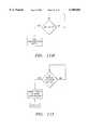
- FIG. 9is a schematic representation of the water overflow detection subsystem of the user monitoring system of FIG. 1;
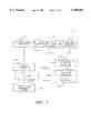
- FIG. 1a block diagram representation of a user monitoring system 100 in accordance with a preferred embodiment of the present invention.
- the monitoring systemmay be used to monitor and assist elderly persons, functionally impaired persons or the like on a temporary short-term basis or on a long-term basis.
- the user monitoring system 100includes a microprocessor based system controller device 110 linked to various sensors which are provided within a number of activity detection subsystems 112-128.
- Activity detection subsystems 112-123are adapted to monitor various activities of daily living of the user of the monitoring system 100.
- the in-home telephone 132which is located within the user living area being monitored and an outside telephone line 144.
- any number of daily living activity detection subsystemsmay be provided within the user monitoring system 100 of the present invention.
- the detection subsystems provided in one embodimentmay include a movement detection subsystem 112, a medication self-management detection subsystem 116, and a stove safety detection subsystem 120.
- the user monitoring system 100may be coupled to a computer based case monitoring system 148 by way of a telephone line 144.
- Formal and informal care giversmay be provided with information to determine whether short and long term intervention is required using the data transmitted to the case monitoring system 148.
- any method of transmitting messages to system 148may be used. For example, messages may be transmitted by an add-on fiber optic cable box or a portable transmitter.
- the user monitoring system 100integrates sensor data from different activity domains to make a number of determinations at predetermined times on a twenty-four hour basis.
- One activity domain determination within the user monitoring system 100includes movement of the person being monitored. In this movement domain determinations are made by the movement detection subsystem 112 whether the user is up and around. The detection information which results from this determination by movement detection subsystem 112 is transmitted to the system controller device 110.
- Stove usageis another activity domain which is monitored by the user monitoring system 100.
- this activity domaindeterminations are made as to whether a stove has been left on inappropriately. Detection information in accordance with this determination is transmitted to the system controller device 110. This determination may be made by differing embodiments of the stove safety detection subsystem 120 depending on whether the stove being monitored by detection subsystem 120 is a gas stove or an electric stove.
- auxiliary systems subsystems 128may include, for example, other potentially harmful appliances such as irons or electric space heaters.
- System controller device 110also receives detection information representative of the determination of the detection subsystems 116, 128.
- the system controller device 110includes a computer 208 and a radio frequency multichannel receiver 212.
- the computer 208may be any type of computer capable of running C++or any similar functionally equivalent object code.
- the various channels of the radio frequency receiver 212are provided within system controller device 110 for receiving radio freguency signals transmitted from the various detection subsystems 112-128 by way of detection system antennas provided within the various detection subsystems 112-128. It will be understood that a sufficient number of information channels required to accommodate the number of detectors should be provided within system 100. These communication channels may ze provided, for example, by a number of radio frequency channels within radio frequency receiver 212.
- the various channels of the radio frequency receiver 212thus serve as detection information channels for receiving detection information within the monitoring system 100.
- any information channel or information conduit or means for applying informationmay be used to apply information from detection subsystems 112-128 to system controller 110.
- the system controller device 110is also provided with an AC power line transmitter 202 for applying control signals to the various detection subsystems 112-128 and to the remote monitoring site 148. Additionally, a system controller modem 204, and a telephone interfacing circuit 202 are present within the system controller 110.
- the radio frequency receiver 212may be a pulsed radio frequency device.
- the power line transmitter 202 of the system controller device 110is a conventional system for turning controlled appliances on and off. In the preferred embodiment of the user monitoring system 100, this control may be accomplished by sending pulsed radio frequency signals through the AC lines of the living areas of the user as understood by those skilled in the art.
- the use of different pulsed signals, decodable by different detection subsystems,is effective to provide any required number of control information channels for applying control signals to detection subsystems 112-128 by system controller 110.
- the transmission of control information from the system controller device 110 to the various detection subsystems 112-128may be performed by any suitable information channels.
- the controller modem 204 of the system controller device 110may be a conventional modem capable of providing known incoming and outgoing modem protocols.
- the outgoing protocols of the controller modem 204may be used for data transfer from the system controller device 110 to the case monitoring site 148 or to other locations by way of telephone line 144.
- the incoming protocols of the system controller modem 204may be used for reprogramming various monitoring and intervention parameters of the user monitoring system 100. Reprogramming may be performed either by the remote case monitoring site 148 through the controller modem 204 or directly to the system controller device 110. Additionally, the incoming protocols may be used for any type of communication with the user monitoring system 100.
- the local telephone interface circuit 206 of the system controller device 110provides several functions within the user monitoring system 100. It transmits incoming calls received by the user monitoring system 100 by way of the telephone line 144 to the in-home telephone 132.
- the telephone interface device 206also connects ringing voltage as well as synthesized voice messages from the voice data storage device 210 to the in-house telephone 132 on command to provide messages to the user by way of the in-home telephone 132. It also makes several determinations regarding the state of the in-house telephone 132. For example, determinations when the in-home telephone 132 is off-hook, when the in-home telephone 132 is not off-hook, and whether the number one has been pressed on the in-home telephone 132 may be made by the local telephone interface circuit 206.
- the user monitoring system 100operates in a home mode and in an away mode.
- the away mode of the user monitoring system 100may be selected by pressing a dedicated away switch (not shown) located in a convenient location in the home of the user. Additionally, the away mode of user monitoring system 100 may be remotely set from the case management monitoring host site 148.
- the home mode of the user monitoring system 100may be passively set, for example, by the opening of a door when the user returns home.
- a reprogrammable microprocessorreceives detection information, makes determinations as set forth herein, and provides control information accordingly.
- a reprogrammable microprocessorreceives detection information, makes determinations as set forth herein, and provides control information accordingly.
- any type of control circuitry capable of performing the operations set forth hereinmay be used within the user monitoring system 100.
- FIG. 3there is shown a block diagram representation of a preferred embodiment of the movement activity detection subsystem 112 of the user monitoring system 100.
- movement sensed by the movement activity detection subsystem 112is assumed to indicate that the user being monitored is up and around.
- the configuration of the movement detection subsystem 112may vary according to the differing living areas being monitored by user monitoring system 100.
- the movement detection subsystem 112includes at least one and preferably several motion sensors such as motion sensor 304 positioned at spaced locations within the home of the user or a conventional reed switch door opening such as sensor detector 308.
- the motion sensor 304 and the reed switch 308are provided for determining whether there is movement or activity within the living area being monitored by the user monitoring system 100.
- the detection subsystem 112only a single motion sensor 304 may be provided.
- the single motion sensor 304is preferably placed between the bed of the user and the bathroom.
- a single reed switchis provided within the movement detection subsystem 112
- itis preferably placed on the door of the bathroom.
- Such basic configurations of the movement detection subsystem 116are effective to determine whether the user being monitored has gotten out of bed or has gone to the bathroom after a predetermined time.
- a motion transmitter 306 of the motion detection subsystem 112transmits a radio frequency signal by way of the motion antenna 302.
- This motion signalrepresenting an activity of daily living by the user is received by the system controller device 110 of the user monitoring system 100. It is therefore activity of daily living information which indicates that the detected user movement has occurred within the home being monitored by the user monitoring system 100.
- movement and activity sensors 304, 308may be required within the movement detection subsystem 112 of the user monitoring system 100.
- the movement detection subsystem 112.Inappropriate periods of user inactivity as indicated by sensors 304, 308 or other sensor disposed in these locations may indicate a medical emergency.
- a plurality of motion sensors or switchessuch as reed switches may be placed in locations within the living area being monitored and that there are no theoretical limitations in the number of such devices which may be used with the movement detection system 112.
- the system controller device 110may place a telephone call to the user by way of the telephone 132 in order to determine whether the user is having a problem. If the telephone call placed by the system controller device 110 is answered, the user is prompted by the system controller device 110 to depress a predetermined key on the in-home telephone 132. For example, the user may be prompted to press the telephone key indicating the number one. If the user complies with the prompt from the system controller device 110 the wake up monitor phase of the user monitoring system 100 is complete.
- the activity movement detection subsystem 112 of the user monitoring system 100merely monitors all system status changes within system 100. This includes monitoring and storing information from the motion detectors 304, 308 representing movement and the opening and closing of doors, the usage of medication, the usage of the stove and appliances, and any other auxiliary devices which may be monitored by the user monitoring system 100.
- Each status change detected by the user monitoring system 100is assumed to indicate activity of the user being monitored.
- the user monitoring system 100returns to the wake up monitor phase and places a telephone call to the user as previously described.
- the period of inactivity required for the user monitoring system 100 to return to the wake up monitor phaseis adjustable depending upon the habits of a particular user but may, for example, be two and one-half hours.
- the user monitoring system 100When the user monitoring system 100 is in the away mode it does not record or report any activities. It merely waits for active or passive resetting of the home mode as previously described. Active resetting of the home mode of the user monitoring system 100 occurs when the user activates a dedicated home/away switch which may be mounted at any convenient location. Passive resetting of the mode of the user monitoring system 100 may occur when the user returns and changes the status of any detection subsystem 112-128.
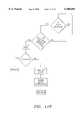
- the medication self-management detection subsystem 116comprises a medication holder 404 which is a specialized portable holder or caddy for holding at least one medication container 402 in a corresponding container opening 404.
- a plurality of the medication containers 402may be installed within their corresponding container openings 406 in the portable medication holder 404 when the user being monitored is not removing medication from them.
- the medication containers 402 and the container openings 406 within the medication holder 404may be color coded. In this method the colors of a selected medication container 402 and its container opening 406 match each other.
- each container opening 406 of the medication holder 404may be provided with a matching colored light 408. The colored lights 408 assist the user in returning a removed medication container 402 to its correct container opening 406.
- the radio frequency signal provided by the medication transmitter 424 when it is activated by a switch 416is pulse code modulated by pulse coder 420.
- the modulating of the pulse coder 420is performed in a series of differing manners according to which switch 416 within the medication container 404 is opened.
- the selected pulse coded signal from the medication transmitter 424is received, decoded, and stored by the system controller device 110 of the user monitoring system 100.
- the colored light 408turns off and the transmission from the medication transmitter 424 to the system controller device 110 terminates. The termination of the transmission by the medication transmitter 424 indicates to the system controller device 110 that the medication container 402 has been returned to its opening 406 in the medication holder 404.
- the medications within a medication holder 404may be organized according to the time of day they are taken. In this type of organization medications which are taken at the same time may be loaded together into a single compartment within the medication holder 404. A plurality of these compartments may be provided within the medication self-management detection system 116. The opening and closing of these compartments may be monitored by the medication self-management detection system 116 in substantially the same manner as previously described with respect to monitoring the removal of the medication containers 402 from the openings of the medication holder 404.
- the pulsed transmissions from the medication transmitter 424 to the system controller device 110may carry a plurality of differing codes corresponding to the plurality of differing medication containers 402.
- Each pulse codecorresponds to an individual medication container 402 and indicates when its corresponding medication container 402 is currently removed from the medication holder 404.
- the system controller device 110 of the user monitoring system 100is programmed to record the times of removal and replacement of each medication container 402 within medicine holder 404 according to these transmissions. It is also programmed to determine scheduled on-time removals of each of the medication containers 404 from the medicine holder 404. Compliance data representative of these determinations according to transmissions from the medication self-management detection system 116 may be transferred to the case monitoring site 148 for intervention decisions.
- the system controller device 110 of the user monitoring system 100may be programmed to determine when user compliance does not conform to a scheduled regimen. After a selected time period, for example, one-half hour, without user compliance, voice data from the voice data storage device 224 may be applied by the controller device 110 to-the in-home telephone 132 to remind the user to take medications.
- the system controller device 110may also provide general and specific reminders and inquiries to the user concerning medications after the user returns from being away. These reminders and inquiries may be made with respect to all medications or with respect to specific medications.
- the system controller device 110may also provide specific time scheduled reminders to take medication.
- FIGS. 6, 7there are shown two embodiments of the stove safety detection subsystem 120, the stove safety detection subsystem 600 and an electric stove safety detection subsystem 700.
- the stove safety detection systems 600, 700 of FIGS. 6, 7are preferred alternate embodiments which are adapted for monitoring and controlling gas stoves and electric stoves, respectively.
- the system controller device 110may determine that the gas stove 610 must be shut off in accordance with the coded information from the gas flow monitor 604. If this determination is made by the system controller device, it applies a control signal to the gas stove safety detection subsystem 600 by way of the AC line 630.
- the control signal to the gas stove detection system 600 from the system controller device 110is generated and transmitted by way of the AC power fine transmitter 216 as previously described.
- This control signalis received by the controller receiver 628 of the gas stove safety detection subsystem 600.
- the controller receiver 628instructs a gas shut off valve 608 by way of a step down circuit 608 to terminate gas flow through gas line 602 to the gas stove 610 in response to the control signal. This turns off the gas stove 610.
- an electrical current draw monitoring device 704is provided for use along with the electric stove safety detection system 700.
- the electrical current monitoring device 704is applied to the AC power line 706 which supplies power to the electrical stove 710.
- the AC power line 706 detector subsystem 700is able to indicate the on/off status of the burners of the electric stove 710.
- On/off status informationis coded by the pulse coder 712 and transmitted by an electric stove transmitter 720 by way of antenna 716 to the system controller device 110.
- the system controller device 110may determine that the electric stove 710 must be shut off in accordance with the coded information from the current draw monitor 704 as previously described with respect to the gas stove safety detection system 600. If electric stove 710 is to be shut off, the system controller device 110 applies a control signal to the electric stove safety detection subsystem 700 by way of the AC line 730. This signal is received by a controller receiver 728 of the electric stove safety detection subsystem 700. The controller receiver 728 instructs the electrical trip relay 708 to interrupt electricity through the electrical power supply line 702 to electrical stove 710. This turns electric stove 710 off.
- shut down predetermined control algorithmsare followed in order to determine whether the stove 610, 710 should be turned off.
- These predetermined control algorithmsare executed within the system controller device 110 of the user monitoring system 100.
- the algorithmsoperate upon coded information transmitted from the stove safety detection management subsystems 600, 700 and the movement detection subsystem 112 in the following manner although the other algorithms may be used if desired:
- the sensor devices 632, 732When the sensor devices 632, 732 detect smoke within the home of the user they sound a fire alarm in a conventional manner. Additionally, the detection of smoke by the sensor devices 632, 732 activates subsystem switching circuit which activates the respective smoke detector transmitter 620, 720. In response the smoke detection transmitters 620, 720 provide a pulsed radio frequency control signal by way of the antenna 616. This control signal conveys information to the system controller device 110 of the user monitoring system 100. The information transmitted by the subsystems 600, 700 in this-manner indicates to the system controller device 110 that smoke was detected by a sensor device 632, 732. It may also indicate which particular sensor device is triggered if more than one sensor device 632, 732 is used within a subsystem 600, 700.
- the water overflow detection subsystem 124may be installed on plumbing fixtures such as sinks and bathtubs within the home of the user being monitored by the user monitoring system 100.
- a water level sensing device 1004 and a remote controlled shut-off device 1030are provided in communication with the system controller device 110 of the user monitoring system 100.
- the water overflow detection subsystem 124is similar to the gas stove safety subsystem 600 previously described.
- the water level sensing device 1004 or water level monitor 1004sends information to the system controller device 110 by means of a pulsed radio frequency water level transmitter 1002.
- the system controller device 110is programmed to initiate shut off of water within overflow detection subsystem 124 by means of a radio frequency remote control signal.
- the radio frequency remote control signalis transmitted through the home of the user by way of the AC lines.
- the control signal from the system controller device 110is received by the controller receiver 1044, stepped down by step down circuit 1040.
- the stepped down signalis used to control resetable electrically controlled water valves 1034, 1038.
- the electrically controlled valve 1034may control water flow from an inlet pipe 1026 to a tub supply pipe 1028.
- the electronically controlled valve 1038may control water flow from an inlet pipe 1026 to a sink inlet pipe 1032.
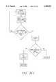
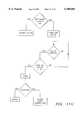
- FIGS. 11A-11Mthere are shown flow chart representations of the operations of the various subsystems of the user monitor system 100.
- FIG. 11Ais a flow chart representation of a method for determining which of the various subsystems has initiated an event for processing by the controller 110.
- FIG. 11Bis a flow chart representation of a method for determining whether the user has arisen by a designated wake up time. This method may be performed in response, for example, to a signal from the motion sensor 304.
- FIG. 11Cis a representation of a method for determining whether the user is complying with the medication schedule as indicated by the subsystem 116.
- FIG. 11Dis a representation of methods for determining whether a stove has been left on according to the subsystem 600 and whether the smoke detector 732 has been activated.
- FIG. 11Eis a flow chart representation of a method for turning off the stove 610, 710.
- FIG. 11Fis a flow chart representation of a method for controlling water flow according to the subsystem 124. A pseudocode representation of a method for controlling water flow is set forth in Table I.
- FIG. 11Jis a flow chart representation of a method for reading switches within the user monitoring system 100.
- a pseudocode representation of a method for reading switchesis set forth in Table II.
- the user monitoring system 100can determine, for example, whether users are up and about in their homes and whether they are having difficulty managing their medications. It can also be determined whether the user has accidentally left a stove on or has failed to get out of bed a predetermined number of hours after a usual waking time. If the user monitoring system 100 detects any of these or other problems it can then call the user on the in-home telephone 132 to provide a reminder about the medications, stove, or other detected problems.
- the remote case monitoring system 148may provide on-line case monitoring of each user by receiving standard information and information designated as priority information and analyzing the received information. In order to do this, the remote case monitoring system 148 converts incoming data on each user into various summary reports which track the activities of the client. This makes it possible to distribute specialized gerontological every day living summary reports to users, family members, case managers, physicians and others. It also makes it possible to collect and act upon the designated priority information which may indicate immediate problems for the user. For example when a user appears not to have gotten out of bed a problem may be indicated.
- the collection of this kind of data by the remote case monitoring system 148may provide an aggregate data base for identifying which users require personal interventions and which do not.
- the remote case monitoring system 148serves as a central hub for the collection, analysis and exchange of information which has direct case management import. It should be understood that in different embodiments of the inventive concept different degrees of autonomy of the local system controller 110 in relation to the remote system 148 are possible. In one embodiment a local system controller 110 may be programmed to perform many functions performed by the remote case monitoring system 148 in another embodiment.
- the dialing and sending of voice messages to a list of relatives and providersmay be performed either by the local system controller 110 or the remote case monitoring system 148.
- the primary function of the local system controller 110is to provide lower level case management of local observations and decisions and the primary function of the remote case monitoring system 148 is to provide higher level case management to enable long term interpretation of the data obtained from the user monitor system 100 and intervention in view of the long-term interpretation.
- the user monitoring system 100may be programmed to take corrective actions when certain problems are detected. For example, if the user being monitored has not gotten out of bed by a predetermined time the user monitoring system 100 may call the user on the telephone 132. If there is no answer to the telephone call the user monitoring system 100 may be programmed to automatically transmit this information to the remote case monitoring site 148.
- a social worker, health professional or designated family member at the remote case monitoring site 148may respond to the transmitted information according to a predetermined protocol.
- the user monitoring system 100may provide control signals within the home of the user. For example, if the user monitoring system 100 of the present invention determines that a stove has been left on, the user monitoring system 100 itself can turn off the stove.
- the remote case monitoring system 148may receive information from the distributed user monitoring systems 100 on an immediate basis or at predetermined time intervals. For example, the remote case monitoring system 148 may receive information hourly, daily or weekly basis. If one of the clients does not get out of bed within a predetermined time duration and does not answer the telephone, the local system controller 110 of the user monitoring system 100 at that client's house may call the case management site. At the case management site, this event may be brought to the immediate attention of the human case monitor, for example, by means of a computer screen. The remote case manager may examine individual case and data records for the client being monitored to learn the predetermined response for the monitored person when the reported event occurs.
- Likely interventions required of personnel at the case management sitemay include calling a local case manager, a hospital social worker or a local next of kin.
- Other actions the remote case monitor may executeinclude calling the user, remotely downloading the last twenty-four or forty-eight hours worth of event summary information from the local user monitoring system 100 and remotely initiating a diagnostic sequence on the local user monitoring system 100.
- the protocol of procedures for intervention by the remote case monitor 148may differ from one remote case monitoring system 148 to another and from one user to another. It is anticipated in the preferred embodiment of the invention that various intervention decisions such as who to call when predetermined events occur and what messages to deliver may be carried out by a machine intelligence expert system (not shown) at the remote case monitoring system 148 or by a person or a combination of both.
- the local user monitoring system 100may also be programmed to carry out such decisions as who to call when appropriate. For example, the user monitoring system 100 may have a contact list of people to contact in various emergencies.
- the remote case monitoring system 148routinely receives downloaded data from individual user monitoring systems 100 at predetermined intervals. This data is interpreted on the individual and aggregate level by means of trend analysis software which detects larger than statistically normal deviations from event pattern measurements.
- the remote case monitoring system 148may use this analysis to produce periodic summary reports of events relating to everyday living tasks in the home environment of the user. More specifically these reports may be used to detect certain event classes, to weight them in terms of their relative importance and to compare them with baselines of task performance. The events weighed with respect to their importance may include getting out of bed, managing medication, the proper control of a stove, the proper control of water flow, and the proper control of selected electrical appliances.
- gerontological living summary reportsmay be prepared in machine form and paper form at the remote case management system 148 for distribution to predesignated parties involved in the case management of the user of the user monitoring system 100. These parties may include the users themselves, relatives of the user, case manager social workers, physicians and other appropriate formal and informal providers.
- Information transmitted to the system controller 110 of the local user monitoring system 100 from the remote case monitoring system 148may include three different types of commands: queries, diagnostics and settings.
- the query commandsrequest the downloading of specific information from the memory of the user monitoring system 100 to the remote case monitoring system 148.
- the requested informationforms the basis of the gerontological everyday living events report along with specific information necessary for case monitoring by the remote system 148. For example the status of different subsystems of the user monitoring system 100 might be made available to the remote system 148 when the motion subsystem 112 indicates that the user has not gotten up in the morning.
- the diagnostic commands to the local user monitoring system 100test the different subsystems of the system 100 by suppressing the ability of the system 100 to either call out interventions or change settings on any of the remotely controlled devices while at the same time initiating a sequence of event codes which indicate the presence of various kinds of problems as if they were indicated by the different subsystems.
- the setting commands from the remote case management system 148 to the user monitoring system 100reset the parameters on the timers within the user monitoring system 100 as well as other variable values for the decisions made in the decision trees described hereinbelow. These parameters may include, but are not limited to, the time of waking up, the times for taking different medications and the length of time which should elapse prior to turning off the stove.
- Priority specific data transferis initiated by the local system controller 110 by means of dialing the remote case monitoring system 148 by way of the telephone line 144 or by means of another data link (not shown) and indicating the presence of a problem which the remote case monitoring system 148 must detect, record and act upon.
- the trend analysis reportmay be a monthly paper or machine report which provides several indicators of performance on different areas of everyday living monitored by the user monitoring system 100. These areas may include waking and sleeping, medication management, stove management, water flow management and the operation of additional appliances.
- the raw data for this reportis based on the event log data transferred from the local system controller 110 remote system using standard data transfer and priority specific modes. The raw data is used to provide a continuous baseline of the successful and not successful completion of the five task areas.
- a usermay use the stove fifty-five times and leave it on in violation of the programmed protocol two times.
- the monthly report line for the stove categorymight then show fifty-five uses and two usage errors.
- usage errorsmay be classified according to level of importance by means of a weighting system. An error of, for example, skipping one medication may be weighted as considerably less significant compared with an error of leaving the stove on and leaving the apartment for several hours.
- the reportis intended to contain a ranking system to reflect the potential negative impacts of different errors.
- the trend analysis reportcan plot deviations in behavior indicating changes in plot trend. For example, the trend analysis report can plot waking and sleeping hours and the number of times a user goes to the bathroom. While none of this in itself indicates a situation requiring intervention, sudden changes in sleep habits, bathroom use, even appliance use may indicate sudden changes in health or cognitive well being requiring a relative or a case management social worker or case management social worker or a physician to visit or interview the user.
- monitoring system 100may be used to monitor any type of patient, for example, infants and burn victims. Additionally, it will be understood that, using the correct sensors, monitoring system 100 may monitor any parameters relevant to these patients, for example, ambient temperature, body temperature and blood pressure. In general, anything which may be sensed by a sensor and converted into an electrical signal may be monitored by the monitoring system 100. Additionally, the data could be made available to a doctor prior to routine doctor's appointments in addition to being used to compile reports at the remote monitoring site 148. The system could be monitored by a friend or relative rather than by professionals at a remote monitoring site.
Landscapes
- Health & Medical Sciences (AREA)
- General Health & Medical Sciences (AREA)
- Gerontology & Geriatric Medicine (AREA)
- Business, Economics & Management (AREA)
- Emergency Management (AREA)
- Physics & Mathematics (AREA)
- General Physics & Mathematics (AREA)
- Psychiatry (AREA)
- Psychology (AREA)
- Social Psychology (AREA)
- Engineering & Computer Science (AREA)
- Human Computer Interaction (AREA)
- Alarm Systems (AREA)
Abstract
Description
TABLE I ______________________________________ Is there a flow If yes Is there a change of state If yes send event to main controller If no recycle to flow monitor If no Is there a change of state If yes send event to main controller If no recycle to flow monitor Is there water overflow If yes Send event to main controller If no Is there water warning If yes send event to main controller If no recycle to water overflow ______________________________________
TABLE II ______________________________________ Is the switch open If yes Is there a state change If yes send event to controller turn off light If no recycle to open test If no Is there a state change If yes send event to main controller turn on light If no recycle to open test ______________________________________
TABLE III ______________________________________ Is the automatic timer set If yes Is there current draw If yes Is turn off timer exceeded If yes turn off appliance send event to controller If no recycle to AT set If no Is turn on time exceeded If yes turn on appliance send event to controller If no recycle to AT set If no Is there current draw If yes Is there a state change If yes send event to main controller If no recycle to AT set If no Is there a state change If yes send event to main controller If no recycle to AT set ______________________________________
Claims (10)
Priority Applications (2)
| Application Number | Priority Date | Filing Date | Title |
|---|---|---|---|
| US08/972,425US6108685A (en) | 1994-12-23 | 1997-11-18 | System for generating periodic reports generating trend analysis and intervention for monitoring daily living activity |
| US13/077,684US8321562B2 (en) | 1994-12-23 | 2011-03-31 | Determining a value according to a statistical operation in a monitored living area |
Applications Claiming Priority (2)
| Application Number | Priority Date | Filing Date | Title |
|---|---|---|---|
| US08/363,495US5692215A (en) | 1994-12-23 | 1994-12-23 | System for generating periodic reports, generating trend analysis, and intervention in accordance with trend analysis from a detection subsystem for monitoring daily living activity |
| US08/972,425US6108685A (en) | 1994-12-23 | 1997-11-18 | System for generating periodic reports generating trend analysis and intervention for monitoring daily living activity |
Related Parent Applications (1)
| Application Number | Title | Priority Date | Filing Date |
|---|---|---|---|
| US08/363,495ContinuationUS5692215A (en) | 1994-12-23 | 1994-12-23 | System for generating periodic reports, generating trend analysis, and intervention in accordance with trend analysis from a detection subsystem for monitoring daily living activity |
Related Child Applications (1)
| Application Number | Title | Priority Date | Filing Date |
|---|---|---|---|
| US46533299AContinuation | 1994-12-23 | 1999-12-17 |
Publications (1)
| Publication Number | Publication Date |
|---|---|
| US6108685Atrue US6108685A (en) | 2000-08-22 |
Family
ID=23430467
Family Applications (2)
| Application Number | Title | Priority Date | Filing Date |
|---|---|---|---|
| US08/363,495Expired - LifetimeUS5692215A (en) | 1994-12-23 | 1994-12-23 | System for generating periodic reports, generating trend analysis, and intervention in accordance with trend analysis from a detection subsystem for monitoring daily living activity |
| US08/972,425Expired - LifetimeUS6108685A (en) | 1994-12-23 | 1997-11-18 | System for generating periodic reports generating trend analysis and intervention for monitoring daily living activity |
Family Applications Before (1)
| Application Number | Title | Priority Date | Filing Date |
|---|---|---|---|
| US08/363,495Expired - LifetimeUS5692215A (en) | 1994-12-23 | 1994-12-23 | System for generating periodic reports, generating trend analysis, and intervention in accordance with trend analysis from a detection subsystem for monitoring daily living activity |
Country Status (3)
| Country | Link |
|---|---|
| US (2) | US5692215A (en) |
| AU (1) | AU4687596A (en) |
| WO (1) | WO1996020449A1 (en) |
Cited By (96)
| Publication number | Priority date | Publication date | Assignee | Title |
|---|---|---|---|---|
| US20020147638A1 (en)* | 2001-04-05 | 2002-10-10 | International Business Machines Corporation | Business method for e-commerce through customized activity-based advertising |
| US20020145514A1 (en)* | 2001-04-04 | 2002-10-10 | Tel-Tron Systems Solutions | Emergency call system using wireless, direct connect and telephone subsystems |
| US6469751B1 (en)* | 1999-07-16 | 2002-10-22 | Fujitsu Limited | Remote control device and computer readable recording medium for recording a remote control program |
| WO2002057870A3 (en)* | 2001-01-19 | 2003-01-30 | Cybercare Technologies Inc | System and method for providing medication management |
| US20030098793A1 (en)* | 2001-10-01 | 2003-05-29 | Tilo Christ | System for automatically monitoring persons in a domestic environment |
| WO2003058509A1 (en)* | 2002-01-07 | 2003-07-17 | Creo Inc. | Automated system and methods for determing the activity focus of a user in a computerized environment |
| WO2003083800A1 (en)* | 2002-03-28 | 2003-10-09 | Honeywell International Inc. | System and method for automated monitoring, recognizing, supporting, and responding to the behavior of an actor |
| US6646549B2 (en) | 2001-04-04 | 2003-11-11 | Brian Dawson | Emergency call network and system with graphical user interface |
| US20030233660A1 (en)* | 2002-06-18 | 2003-12-18 | Bellsouth Intellectual Property Corporation | Device interaction |
| US20030231602A1 (en)* | 2002-06-18 | 2003-12-18 | Bellsouth Intellectual Property Corporation | Device interaction aggregator |
| US20040078463A1 (en)* | 2002-02-25 | 2004-04-22 | General Electric Company | Method and apparatus for minimally invasive network monitoring |
| US6765992B2 (en) | 2001-04-04 | 2004-07-20 | Brian Dawson | Emergency call system and method with attendant and resident pendant actuation |
| US6796799B1 (en)* | 1999-07-23 | 2004-09-28 | Matsushita Electric Industrial Co., Ltd. | Behavior determining apparatus, care system, care residence and behavior information specifying apparatus and system |
| US6889207B2 (en) | 2002-06-18 | 2005-05-03 | Bellsouth Intellectual Property Corporation | Content control in a device environment |
| US20050131736A1 (en)* | 2003-12-16 | 2005-06-16 | Adventium Labs And Red Wing Technologies, Inc. | Activity monitoring |
| US20050137465A1 (en)* | 2003-12-23 | 2005-06-23 | General Electric Company | System and method for remote monitoring in home activity of persons living independently |
| US20050224083A1 (en)* | 2003-12-19 | 2005-10-13 | Crass Richard E | Intravenous medication harm index system |
| US20050234310A1 (en)* | 2004-03-10 | 2005-10-20 | Majd Alwan | System and method for the inference of activities of daily living and instrumental activities of daily living automatically |
| US20050237179A1 (en)* | 2004-04-09 | 2005-10-27 | General Electric Company | Device and method for monitoring movement within a home |
| US20050240304A1 (en)* | 2004-04-21 | 2005-10-27 | Matthew York | Method and apparatus for automatic health monitoring |
| US20050237206A1 (en)* | 2004-04-09 | 2005-10-27 | General Electric Company | System and method for determining whether a resident is at home or away |
| US20050278409A1 (en)* | 2000-11-09 | 2005-12-15 | Kutzik David M | Determining a value according to a statistical operation in a monitored living area |
| US20060055543A1 (en)* | 2004-09-10 | 2006-03-16 | Meena Ganesh | System and method for detecting unusual inactivity of a resident |
| US7016888B2 (en) | 2002-06-18 | 2006-03-21 | Bellsouth Intellectual Property Corporation | Learning device interaction rules |
| US20060071798A1 (en)* | 2004-10-01 | 2006-04-06 | Kiff Liana M | Mobile telephonic device and base station |
| US7039698B2 (en) | 2002-06-18 | 2006-05-02 | Bellsouth Intellectual Property Corporation | Notification device interaction |
| US7091865B2 (en) | 2004-02-04 | 2006-08-15 | General Electric Company | System and method for determining periods of interest in home of persons living independently |
| US20060234793A1 (en)* | 1995-11-22 | 2006-10-19 | Walker Jay S | Method and apparatus for outputting a result of a game via a container |
| US20060261962A1 (en)* | 2005-03-24 | 2006-11-23 | France Telecom | Process and device for remotely tracking a person's activity in a building |
| US20060276931A1 (en)* | 1995-11-22 | 2006-12-07 | Walker Jay S | Systems and methods for improved health care compliance |
| US20070035415A1 (en)* | 2005-08-11 | 2007-02-15 | Dawson N R | System and method for programming a code of an emergency call transmitter |
| US20070035402A1 (en)* | 2005-08-11 | 2007-02-15 | Dawson N R | System and method for determining the location of a resident during an emergency within a monitored area having a plurality of residences |
| US7185282B1 (en) | 2002-08-29 | 2007-02-27 | Telehealth Broadband, Llc | Interface device for an integrated television-based broadband home health system |
| US20070112530A1 (en)* | 2003-07-28 | 2007-05-17 | Dean Kamen | Systems and methods for distributed utilities |
| US20070123754A1 (en)* | 2005-11-29 | 2007-05-31 | Cuddihy Paul E | Non-encumbering, substantially continuous patient daily activity data measurement for indication of patient condition change for access by remote caregiver |
| US20070152837A1 (en)* | 2005-12-30 | 2007-07-05 | Red Wing Technologies, Inc. | Monitoring activity of an individual |
| US20070192174A1 (en)* | 2005-12-30 | 2007-08-16 | Bischoff Brian J | Monitoring task performance |
| US20070195703A1 (en)* | 2006-02-22 | 2007-08-23 | Living Independently Group Inc. | System and method for monitoring a site using time gap analysis |
| US20080048826A1 (en)* | 2006-08-10 | 2008-02-28 | Kavita Agrawal | System and method for controlling, configuring, and disabling devices in a healthcare system |
| US20080052970A1 (en)* | 2006-09-06 | 2008-03-06 | Chang Sup Lee | Talking iron |
| US20080084296A1 (en)* | 2000-11-09 | 2008-04-10 | David Kutzik | System for Maximizing the Effectiveness of Care Giving |
| US20080103813A1 (en)* | 2006-10-12 | 2008-05-01 | Kavita Agrawal | System and method for portable safeguard context in a patient's room |
| US20080157966A1 (en)* | 2006-12-27 | 2008-07-03 | Motorola, Inc. | Monitoring for radio frequency enabled items based on activity profiles |
| US20080157971A1 (en)* | 2006-12-27 | 2008-07-03 | Francesca Schuler | Dynamic updating of product profiles for active lifestyles |
| WO2008082767A3 (en)* | 2006-12-27 | 2008-08-21 | Motorola Inc | Active lifestyle management |
| US7420472B2 (en) | 2005-10-16 | 2008-09-02 | Bao Tran | Patient monitoring apparatus |
| US20080266093A1 (en)* | 2007-04-26 | 2008-10-30 | Motorola, Inc. | Monitoring for radio frequency enabled items based on shared group activity profiles |
| US7502498B2 (en) | 2004-09-10 | 2009-03-10 | Available For Licensing | Patient monitoring apparatus |
| US20090125333A1 (en)* | 2007-10-12 | 2009-05-14 | Patientslikeme, Inc. | Personalized management and comparison of medical condition and outcome based on profiles of community patients |
| US7539532B2 (en) | 2006-05-12 | 2009-05-26 | Bao Tran | Cuffless blood pressure monitoring appliance |
| US7539533B2 (en) | 2006-05-16 | 2009-05-26 | Bao Tran | Mesh network monitoring appliance |
| US7558622B2 (en) | 2006-05-24 | 2009-07-07 | Bao Tran | Mesh network stroke monitoring appliance |
| US7801745B2 (en) | 2000-03-10 | 2010-09-21 | Walker Digital, Llc | Methods and apparatus for increasing and/or monitoring a party's compliance with a schedule for taking medicines |
| US20100277309A1 (en)* | 2009-04-29 | 2010-11-04 | Healthsense, Inc. | Position detection |
| US7835926B1 (en) | 2002-08-29 | 2010-11-16 | Telehealth Broadband Llc | Method for conducting a home health session using an integrated television-based broadband home health system |
| US8006511B2 (en) | 2007-06-07 | 2011-08-30 | Deka Products Limited Partnership | Water vapor distillation apparatus, method and system |
| US8069676B2 (en) | 2002-11-13 | 2011-12-06 | Deka Products Limited Partnership | Water vapor distillation apparatus, method and system |
| US20120089269A1 (en)* | 2007-10-02 | 2012-04-12 | Weaver Jason C | Managing energy usage |
| US8282790B2 (en) | 2002-11-13 | 2012-10-09 | Deka Products Limited Partnership | Liquid pumps with hermetically sealed motor rotors |
| US20120259659A1 (en)* | 2010-09-29 | 2012-10-11 | JDJ Enterprises | Medical facility management system |
| US8323189B2 (en) | 2006-05-12 | 2012-12-04 | Bao Tran | Health monitoring appliance |
| US8359877B2 (en) | 2008-08-15 | 2013-01-29 | Deka Products Limited Partnership | Water vending apparatus |
| US20130139138A1 (en)* | 2011-11-28 | 2013-05-30 | Edward A. Kakos | Systems and methods for determining times to perform software updates on receiving devices |
| US8461988B2 (en) | 2005-10-16 | 2013-06-11 | Bao Tran | Personal emergency response (PER) system |
| US8500636B2 (en) | 2006-05-12 | 2013-08-06 | Bao Tran | Health monitoring appliance |
| US8511105B2 (en) | 2002-11-13 | 2013-08-20 | Deka Products Limited Partnership | Water vending apparatus |
| US20130229278A1 (en)* | 2012-03-02 | 2013-09-05 | Kenneth Davis | Heating appliance emergency reminder detection device |
| EP2672472A1 (en)* | 2012-06-07 | 2013-12-11 | Yazid Shammout | Method and apparatus for monitoring the current mobility of persons in private or public spaces |
| US8684900B2 (en) | 2006-05-16 | 2014-04-01 | Bao Tran | Health monitoring appliance |
| US8684922B2 (en) | 2006-05-12 | 2014-04-01 | Bao Tran | Health monitoring system |
| US8750971B2 (en) | 2007-05-24 | 2014-06-10 | Bao Tran | Wireless stroke monitoring |
| US8968195B2 (en) | 2006-05-12 | 2015-03-03 | Bao Tran | Health monitoring appliance |
| US20150088966A1 (en)* | 2013-09-20 | 2015-03-26 | Amazon Technologies, Inc. | Service activity user interface |
| US9060683B2 (en) | 2006-05-12 | 2015-06-23 | Bao Tran | Mobile wireless appliance |
| EP1861839B1 (en) | 2005-03-17 | 2016-08-31 | Innohome Oy | Accessory controlling and tracking the operation of household appliances and entertainment equipment |
| WO2017045025A1 (en) | 2015-09-15 | 2017-03-23 | Commonwealth Scientific And Industrial Research Organisation | Activity capability monitoring |
| WO2017067937A1 (en)* | 2015-10-19 | 2017-04-27 | Koninklijke Philips N.V. | Monitoring a physical or mental capability of a person |
| US9710761B2 (en) | 2013-03-15 | 2017-07-18 | Nordic Technology Group, Inc. | Method and apparatus for detection and prediction of events based on changes in behavior |
| US20170280338A1 (en)* | 2000-05-23 | 2017-09-28 | M2M Solutions Llc | Programmable Communicator |
| US9820658B2 (en) | 2006-06-30 | 2017-11-21 | Bao Q. Tran | Systems and methods for providing interoperability among healthcare devices |
| US9865176B2 (en) | 2012-12-07 | 2018-01-09 | Koninklijke Philips N.V. | Health monitoring system |
| US9879873B2 (en) | 2013-02-07 | 2018-01-30 | Honeywell International Inc. | Building control system with distributed control |
| EP3317865A1 (en)* | 2015-06-30 | 2018-05-09 | Preste, Fausto | Electronic system for remote assistance of a person |
| US10009577B2 (en) | 2002-08-29 | 2018-06-26 | Comcast Cable Communications, Llc | Communication systems |
| US10088186B2 (en) | 2013-02-07 | 2018-10-02 | Honeywell International Inc. | Building management system with power efficient discrete controllers |
| US10094584B2 (en) | 2013-02-07 | 2018-10-09 | Honeywell International Inc. | Building management system with programmable IR codes |
| US10129384B2 (en) | 2014-09-29 | 2018-11-13 | Nordic Technology Group Inc. | Automatic device configuration for event detection |
| US10330335B2 (en) | 2013-02-07 | 2019-06-25 | Honeywell International Inc. | Method and system for detecting an operational mode of a building control component |
| US10359791B2 (en) | 2013-02-07 | 2019-07-23 | Honeywell International Inc. | Controller for controlling a building component of a building management system |
| US10531838B2 (en) | 2014-06-27 | 2020-01-14 | Koninklijke Philips N.V. | Apparatus, system, method and computer program for assessing the risk of an exacerbation and/or hospitalization |
| US11676221B2 (en) | 2009-04-30 | 2023-06-13 | Patientslikeme, Inc. | Systems and methods for encouragement of data submission in online communities |
| US11826681B2 (en) | 2006-06-30 | 2023-11-28 | Deka Products Limited Partneship | Water vapor distillation apparatus, method and system |
| US11884555B2 (en) | 2007-06-07 | 2024-01-30 | Deka Products Limited Partnership | Water vapor distillation apparatus, method and system |
| US11885760B2 (en) | 2012-07-27 | 2024-01-30 | Deka Products Limited Partnership | Water vapor distillation apparatus, method and system |
| US11894139B1 (en) | 2018-12-03 | 2024-02-06 | Patientslikeme Llc | Disease spectrum classification |
| US12417825B2 (en) | 2017-09-15 | 2025-09-16 | Alden Scientific, Inc. | Systems and methods for collecting and analyzing comprehensive medical information |
Families Citing this family (85)
| Publication number | Priority date | Publication date | Assignee | Title |
|---|---|---|---|---|
| US5778882A (en)* | 1995-02-24 | 1998-07-14 | Brigham And Women's Hospital | Health monitoring system |
| US6034622A (en)* | 1995-08-18 | 2000-03-07 | Robert A. Levine | Location monitoring via implanted radio transmitter |
| US5905436A (en)* | 1996-10-24 | 1999-05-18 | Gerontological Solutions, Inc. | Situation-based monitoring system |
| US5924069A (en)* | 1997-01-30 | 1999-07-13 | Lucent Technologies Inc. | Voice-control integrated field support data communications system for maintenance, repair and emergency services |
| US6032036A (en)* | 1997-06-18 | 2000-02-29 | Telectronics, S.A. | Alarm and emergency call system |
| US20040015132A1 (en)* | 1998-01-06 | 2004-01-22 | Eric Brown | Method for improving patient compliance with a medical program |
| FI109843B (en)* | 1998-04-09 | 2002-10-15 | Ist Oy | Controlled system for real estate automation with man's physiological signals |
| JP3420079B2 (en)* | 1998-09-29 | 2003-06-23 | 松下電器産業株式会社 | Condition detection system |
| TW537880B (en) | 1999-03-11 | 2003-06-21 | Remote Medical Corp | Method for improving patient compliance with a medical program |
| GB2348726A (en)* | 1999-04-07 | 2000-10-11 | Kevin Doughty | Monitoring elderly people |
| US7139790B1 (en) | 1999-08-17 | 2006-11-21 | Microsoft Corporation | Weak leader election |
| US6961763B1 (en) | 1999-08-17 | 2005-11-01 | Microsoft Corporation | Automation system for controlling and monitoring devices and sensors |
| US7133729B1 (en)* | 1999-08-17 | 2006-11-07 | Microsoft Corporation | Pattern-and model-based power line monitoring |
| US6640212B1 (en) | 1999-09-30 | 2003-10-28 | Rodney L. Rosse | Standardized information management system for long-term residence facilities |
| US8894577B2 (en)* | 1999-11-05 | 2014-11-25 | Elite Care Technologies, Inc. | System and method for medical information monitoring and processing |
| US6524239B1 (en)* | 1999-11-05 | 2003-02-25 | Wcr Company | Apparatus for non-instrusively measuring health parameters of a subject and method of use thereof |
| US20010032098A1 (en)* | 1999-12-06 | 2001-10-18 | Avi Kulkarni | Internet ready medical device |
| JP3578959B2 (en)* | 2000-02-24 | 2004-10-20 | 松下電器産業株式会社 | Table tap and monitoring system using the table tap |
| US6373389B1 (en) | 2000-04-21 | 2002-04-16 | Usm Systems, Ltd. | Event driven information system |
| US20020091991A1 (en)* | 2000-05-11 | 2002-07-11 | Castro Juan Carlos | Unified real-time microprocessor computer |
| JP2002063421A (en)* | 2000-06-06 | 2002-02-28 | Matsushita Electric Ind Co Ltd | Computer system for supporting collection of equipment and method for supporting collection of equipment using computer system |
| US6898783B1 (en)* | 2000-08-03 | 2005-05-24 | International Business Machines Corporation | Object oriented based methodology for modeling business functionality for enabling implementation in a web based environment |
| US6684388B1 (en) | 2000-08-22 | 2004-01-27 | International Business Machines Corporation | Method for generating platform independent, language specific computer code |
| US7171455B1 (en) | 2000-08-22 | 2007-01-30 | International Business Machines Corporation | Object oriented based, business class methodology for generating quasi-static web pages at periodic intervals |
| US6853994B1 (en) | 2000-08-30 | 2005-02-08 | International Business Machines Corporation | Object oriented based, business class methodology for performing data metric analysis |
| KR100808786B1 (en)* | 2000-09-06 | 2008-03-07 | 주식회사 케이티 | Motion sensing device using multichannel / multilevel and method |
| US7049957B2 (en)* | 2000-11-03 | 2006-05-23 | Wcr Company | Local area positioning system |
| US6968294B2 (en)* | 2001-03-15 | 2005-11-22 | Koninklijke Philips Electronics N.V. | Automatic system for monitoring person requiring care and his/her caretaker |
| US6735477B2 (en) | 2001-07-09 | 2004-05-11 | Robert A. Levine | Internal monitoring system with detection of food intake |
| FR2828317B1 (en)* | 2001-08-01 | 2005-05-13 | Electricite De France | AUTONOMOUS METHOD FOR DETECTING ABNORMAL SITUATIONS ENCOURAGED BY INDIVIDUALS |
| WO2003044755A1 (en)* | 2001-11-08 | 2003-05-30 | Behavioral Informatics, Inc. | Monitoring a daily living activity and analyzing data related thereto |
| GB0207207D0 (en)* | 2002-03-27 | 2002-05-08 | Smith Simon L | Activity and behavioural monitor and alarm device |
| EP1492443A2 (en) | 2002-03-29 | 2005-01-05 | Koninklijke Philips Electronics N.V. | A detection and alarm system |
| US20030236450A1 (en)* | 2002-06-24 | 2003-12-25 | Kocinski Richard J. | System for remotely monitoring and controlling CPAP apparatus |
| US20040116102A1 (en)* | 2002-12-17 | 2004-06-17 | International Business Machines Corporation | Heuristics for behavior based life support services |
| EP1677671A1 (en)* | 2003-10-17 | 2006-07-12 | Koninklijke Philips Electronics N.V. | A device arranged for carrying out a bioelectrical interaction with an individual and a method for on-demand lead-off detection |
| US8406341B2 (en) | 2004-01-23 | 2013-03-26 | The Nielsen Company (Us), Llc | Variable encoding and detection apparatus and methods |
| US7170404B2 (en)* | 2004-07-23 | 2007-01-30 | Innovalarm Corporation | Acoustic alert communication system with enhanced signal to noise capabilities |
| US7656287B2 (en)* | 2004-07-23 | 2010-02-02 | Innovalarm Corporation | Alert system with enhanced waking capabilities |
| US7148797B2 (en)* | 2004-07-23 | 2006-12-12 | Innovalarm Corporation | Enhanced fire, safety, security and health monitoring and alarm response method, system and device |
| US7173525B2 (en) | 2004-07-23 | 2007-02-06 | Innovalarm Corporation | Enhanced fire, safety, security and health monitoring and alarm response method, system and device |
| US7126467B2 (en)* | 2004-07-23 | 2006-10-24 | Innovalarm Corporation | Enhanced fire, safety, security, and health monitoring and alarm response method, system and device |
| US7129833B2 (en) | 2004-07-23 | 2006-10-31 | Innovalarm Corporation | Enhanced fire, safety, security and health monitoring and alarm response method, system and device |
| EP1805918B1 (en) | 2004-09-27 | 2019-02-20 | Nielsen Media Research, Inc. | Methods and apparatus for using location information to manage spillover in an audience monitoring system |
| US7437080B2 (en)* | 2005-02-03 | 2008-10-14 | Stratalight Communications, Inc. | Optical transmission system having optimized filter wavelength offsets |
| CA2601879C (en) | 2005-03-17 | 2017-07-04 | Nielsen Media Research, Inc. | Methods and apparatus for using audience member behavior information to determine compliance with audience measurement system usage requirements |
| US20060259293A1 (en)* | 2005-05-11 | 2006-11-16 | France Telecom | Computerized method and apparatus for automatically generating a natural language description of a person's activities |
| US20070043590A1 (en)* | 2005-08-19 | 2007-02-22 | Grey Trends, Llc | Method and System of Coordinating Communication and Quality Control in Home Care |
| WO2007066270A2 (en)* | 2005-12-08 | 2007-06-14 | Koninklijke Philips Electronics N.V. | Medical sensor having electrodes and a motion sensor |
| US8260252B2 (en) | 2006-10-02 | 2012-09-04 | The Nielsen Company (Us), Llc | Method and apparatus for collecting information about portable device usage |
| US8014726B1 (en) | 2006-10-02 | 2011-09-06 | The Nielsen Company (U.S.), Llc | Method and system for collecting wireless information transparently and non-intrusively |
| US10885543B1 (en) | 2006-12-29 | 2021-01-05 | The Nielsen Company (Us), Llc | Systems and methods to pre-scale media content to facilitate audience measurement |
| US20080221968A1 (en)* | 2007-03-07 | 2008-09-11 | Tamara Gaffney | Method and system for interacting with users of portable devices |
| EP1993053A1 (en)* | 2007-03-20 | 2008-11-19 | British Telecommunications Public Limited Company | Detecting abnormal events |
| US8321556B1 (en) | 2007-07-09 | 2012-11-27 | The Nielsen Company (Us), Llc | Method and system for collecting data on a wireless device |
| US20090150217A1 (en) | 2007-11-02 | 2009-06-11 | Luff Robert A | Methods and apparatus to perform consumer surveys |
| US8264360B2 (en)* | 2007-12-29 | 2012-09-11 | Waterstrike Incorporated | Fluid flow indicator with automatic alarm timer for low pressure/low flow applications |
| US9035781B2 (en) | 2007-12-29 | 2015-05-19 | Waterstrike Incorporated | Apparatus and method for automatically detecting and alerting of gas-out conditions for a gas appliance during operation |
| US9288268B2 (en) | 2008-06-30 | 2016-03-15 | The Nielsen Company (Us), Llc | Methods and apparatus to monitor shoppers in a retail environment |
| US20100016746A1 (en)* | 2008-07-15 | 2010-01-21 | Hampton David R | Personal alerting device for use with diagnostic device |
| TWI384423B (en)* | 2008-11-26 | 2013-02-01 | Ind Tech Res Inst | Alarm method and system based on voice events, and building method on behavior trajectory thereof |
| US8239277B2 (en) | 2009-03-31 | 2012-08-07 | The Nielsen Company (Us), Llc | Method, medium, and system to monitor shoppers in a retail or commercial establishment |
| AU2009345651B2 (en) | 2009-05-08 | 2016-05-12 | Arbitron Mobile Oy | System and method for behavioural and contextual data analytics |
| US20100293132A1 (en)* | 2009-05-15 | 2010-11-18 | Tischer Steven N | Methods, Systems, and Products for Detecting Maladies |
| US8855101B2 (en) | 2010-03-09 | 2014-10-07 | The Nielsen Company (Us), Llc | Methods, systems, and apparatus to synchronize actions of audio source monitors |
| US8301475B2 (en)* | 2010-05-10 | 2012-10-30 | Microsoft Corporation | Organizational behavior monitoring analysis and influence |
| CA3020551C (en) | 2010-06-24 | 2022-06-07 | Arbitron Mobile Oy | Network server arrangement for processing non-parametric, multi-dimensional, spatial and temporal human behavior or technical observations measured pervasively, and related method for the same |
| US8473107B2 (en)* | 2010-08-05 | 2013-06-25 | Sharp Laboratories Of America, Inc. | Offered actions for energy management based on anomalous conditions |
| US8340685B2 (en) | 2010-08-25 | 2012-12-25 | The Nielsen Company (Us), Llc | Methods, systems and apparatus to generate market segmentation data with anonymous location data |
| US8885842B2 (en) | 2010-12-14 | 2014-11-11 | The Nielsen Company (Us), Llc | Methods and apparatus to determine locations of audience members |
| US20130144536A1 (en)* | 2011-12-06 | 2013-06-06 | Welch Allyn, Inc. | Medical Device with Wireless Communication Bus |
| US9021516B2 (en) | 2013-03-01 | 2015-04-28 | The Nielsen Company (Us), Llc | Methods and systems for reducing spillover by measuring a crest factor |
| US9118960B2 (en) | 2013-03-08 | 2015-08-25 | The Nielsen Company (Us), Llc | Methods and systems for reducing spillover by detecting signal distortion |
| US9219969B2 (en) | 2013-03-13 | 2015-12-22 | The Nielsen Company (Us), Llc | Methods and systems for reducing spillover by analyzing sound pressure levels |
| US9191704B2 (en) | 2013-03-14 | 2015-11-17 | The Nielsen Company (Us), Llc | Methods and systems for reducing crediting errors due to spillover using audio codes and/or signatures |
| US9247273B2 (en) | 2013-06-25 | 2016-01-26 | The Nielsen Company (Us), Llc | Methods and apparatus to characterize households with media meter data |
| US9426525B2 (en) | 2013-12-31 | 2016-08-23 | The Nielsen Company (Us), Llc. | Methods and apparatus to count people in an audience |
| US10083459B2 (en) | 2014-02-11 | 2018-09-25 | The Nielsen Company (Us), Llc | Methods and apparatus to generate a media rank |
| JP6602386B2 (en) | 2015-02-18 | 2019-11-06 | コーニンクレッカ フィリップス エヌ ヴェ | Monitoring daily human activities using graphic elements |
| CN104778816A (en)* | 2015-04-01 | 2015-07-15 | 东华大学 | Safety alarm for old people living alone |
| US9924224B2 (en) | 2015-04-03 | 2018-03-20 | The Nielsen Company (Us), Llc | Methods and apparatus to determine a state of a media presentation device |
| US9858788B2 (en) | 2015-04-07 | 2018-01-02 | Vivint, Inc. | Smart bedtime |
| WO2016174662A1 (en) | 2015-04-27 | 2016-11-03 | Agt International Gmbh | Method of monitoring well-being of semi-independent persons and system thereof |
| US9848222B2 (en) | 2015-07-15 | 2017-12-19 | The Nielsen Company (Us), Llc | Methods and apparatus to detect spillover |
| CN105931419B (en)* | 2016-05-17 | 2018-02-09 | 安徽泰然信息技术工程有限公司 | A kind of house intelligent safety protection system |
Citations (10)
| Publication number | Priority date | Publication date | Assignee | Title |
|---|---|---|---|---|
| US4058678A (en)* | 1976-04-07 | 1977-11-15 | Astech, Inc. | Remote signalling to a telephone line utilizing power line carrier signals |
| US4259548A (en)* | 1979-11-14 | 1981-03-31 | Gte Products Corporation | Apparatus for monitoring and signalling system |
| US4319228A (en)* | 1978-12-20 | 1982-03-09 | Daniels Edward H | Portable intrusion alarm |
| US4644320A (en)* | 1984-09-14 | 1987-02-17 | Carr R Stephen | Home energy monitoring and control system |
| US4952928A (en)* | 1988-08-29 | 1990-08-28 | B. I. Incorporated | Adaptable electronic monitoring and identification system |
| US5045839A (en)* | 1990-03-08 | 1991-09-03 | Rand G. Ellis | Personnel monitoring man-down alarm and location system |
| US5086385A (en)* | 1989-01-31 | 1992-02-04 | Custom Command Systems | Expandable home automation system |
| US5127045A (en)* | 1989-11-16 | 1992-06-30 | Cragun David R | Identifying telephone controller system |
| US5267174A (en)* | 1989-09-29 | 1993-11-30 | Healthtech Services Corp. | Interactive medication delivery system |
| US5311185A (en)* | 1992-08-31 | 1994-05-10 | Hochstein Peter A | Supervised personnel monitoring system |
Family Cites Families (22)
| Publication number | Priority date | Publication date | Assignee | Title |
|---|---|---|---|---|
| US3955184A (en)* | 1975-08-18 | 1976-05-04 | Hughes Aircraft Company | Passive infrared room intrusion detector |
| US4418333A (en)* | 1981-06-08 | 1983-11-29 | Pittway Corporation | Appliance control system |
| US4563780A (en)* | 1983-06-29 | 1986-01-14 | Pollack Simcha Z | Automated bathroom |
| US4703325A (en)* | 1984-10-22 | 1987-10-27 | Carrier Corp. | Remote subsystem |
| GB8431883D0 (en)* | 1984-12-18 | 1985-01-30 | Gent Ltd | Transmission system |
| US4665385A (en)* | 1985-02-05 | 1987-05-12 | Henderson Claude L | Hazardous condition monitoring system |
| US4831242A (en)* | 1985-09-12 | 1989-05-16 | Bally Manufacturing Corporation | Control system for health club facilities and equipment |
| US4706689A (en)* | 1985-10-30 | 1987-11-17 | Daniel Man | Implantable homing device |
| US4803625A (en)* | 1986-06-30 | 1989-02-07 | Buddy Systems, Inc. | Personal health monitor |
| US4864588A (en)* | 1987-02-11 | 1989-09-05 | Hillier Technologies Limited Partnership | Remote control system, components and methods |
| US4964065A (en)* | 1987-03-12 | 1990-10-16 | Decibel Products, Inc. | Computer-controlled electronic system monitor |
| US5023901A (en)* | 1988-08-22 | 1991-06-11 | Vorec Corporation | Surveillance system having a voice verification unit |
| US5204670A (en)* | 1988-08-29 | 1993-04-20 | B. I. Incorporated | Adaptable electric monitoring and identification system |
| US4924211A (en)* | 1988-10-28 | 1990-05-08 | Digital Products Corporation | Personnel monitoring system |
| KR900010504A (en)* | 1988-12-31 | 1990-07-07 | 안시환 | Home automation method and apparatus using video tape recorder |
| US5400246A (en)* | 1989-05-09 | 1995-03-21 | Ansan Industries, Ltd. | Peripheral data acquisition, monitor, and adaptive control system via personal computer |
| US4951032A (en)* | 1989-06-15 | 1990-08-21 | Langsam Andrew S | Crib rail safety annunciator |
| US5084875A (en)* | 1989-12-13 | 1992-01-28 | Joseph Weinberger | System for automatically monitoring copiers from a remote location |
| US5228449A (en)* | 1991-01-22 | 1993-07-20 | Athanasios G. Christ | System and method for detecting out-of-hospital cardiac emergencies and summoning emergency assistance |
| US5266944A (en)* | 1991-06-26 | 1993-11-30 | Bodyguard Technologies, Inc. | Electronic system and method for monitoring abusers for compliance with a protective order |
| JP3144030B2 (en)* | 1992-02-24 | 2001-03-07 | 東陶機器株式会社 | Health management network system |
| US5441047A (en)* | 1992-03-25 | 1995-08-15 | David; Daniel | Ambulatory patient health monitoring techniques utilizing interactive visual communication |
- 1994
- 1994-12-23USUS08/363,495patent/US5692215A/ennot_activeExpired - Lifetime
- 1995
- 1995-12-21WOPCT/US1995/016752patent/WO1996020449A1/enactiveApplication Filing
- 1995-12-21AUAU46875/96Apatent/AU4687596A/ennot_activeAbandoned
- 1997
- 1997-11-18USUS08/972,425patent/US6108685A/ennot_activeExpired - Lifetime
Patent Citations (10)
| Publication number | Priority date | Publication date | Assignee | Title |
|---|---|---|---|---|
| US4058678A (en)* | 1976-04-07 | 1977-11-15 | Astech, Inc. | Remote signalling to a telephone line utilizing power line carrier signals |
| US4319228A (en)* | 1978-12-20 | 1982-03-09 | Daniels Edward H | Portable intrusion alarm |
| US4259548A (en)* | 1979-11-14 | 1981-03-31 | Gte Products Corporation | Apparatus for monitoring and signalling system |
| US4644320A (en)* | 1984-09-14 | 1987-02-17 | Carr R Stephen | Home energy monitoring and control system |
| US4952928A (en)* | 1988-08-29 | 1990-08-28 | B. I. Incorporated | Adaptable electronic monitoring and identification system |
| US5086385A (en)* | 1989-01-31 | 1992-02-04 | Custom Command Systems | Expandable home automation system |
| US5267174A (en)* | 1989-09-29 | 1993-11-30 | Healthtech Services Corp. | Interactive medication delivery system |
| US5127045A (en)* | 1989-11-16 | 1992-06-30 | Cragun David R | Identifying telephone controller system |
| US5045839A (en)* | 1990-03-08 | 1991-09-03 | Rand G. Ellis | Personnel monitoring man-down alarm and location system |
| US5311185A (en)* | 1992-08-31 | 1994-05-10 | Hochstein Peter A | Supervised personnel monitoring system |
Cited By (209)
| Publication number | Priority date | Publication date | Assignee | Title |
|---|---|---|---|---|
| US8321562B2 (en) | 1994-12-23 | 2012-11-27 | Intel-Ge Care Innovations Llc | Determining a value according to a statistical operation in a monitored living area |
| US20110237905A1 (en)* | 1994-12-23 | 2011-09-29 | Intel-Ge Care Innovations Llc | Determining a value according to a statistical operation in a monitored living area |
| US8092224B2 (en) | 1995-11-22 | 2012-01-10 | James A. Jorasch | Systems and methods for improved health care compliance |
| US20060234793A1 (en)* | 1995-11-22 | 2006-10-19 | Walker Jay S | Method and apparatus for outputting a result of a game via a container |
| US20060276931A1 (en)* | 1995-11-22 | 2006-12-07 | Walker Jay S | Systems and methods for improved health care compliance |
| US8353752B2 (en) | 1995-11-22 | 2013-01-15 | James A. Jorasch | Method and apparatus for outputting a result of a game via a container |
| US7821404B2 (en) | 1995-11-22 | 2010-10-26 | James A. Jorasch | Systems and methods for improved health care compliance |
| US8556728B2 (en) | 1995-11-22 | 2013-10-15 | James A. Jorasch | Method and apparatus for outputting a result of a game via a container |
| US8262394B2 (en) | 1995-11-22 | 2012-09-11 | James A. Jorasch | Systems and methods for improved health care compliance |
| US6469751B1 (en)* | 1999-07-16 | 2002-10-22 | Fujitsu Limited | Remote control device and computer readable recording medium for recording a remote control program |
| US6796799B1 (en)* | 1999-07-23 | 2004-09-28 | Matsushita Electric Industrial Co., Ltd. | Behavior determining apparatus, care system, care residence and behavior information specifying apparatus and system |
| US8069056B2 (en) | 2000-03-10 | 2011-11-29 | Walker Digital, Llc | Methods and apparatus for increasing and/or for monitoring a party's compliance with a schedule for taking medicines |
| US7801745B2 (en) | 2000-03-10 | 2010-09-21 | Walker Digital, Llc | Methods and apparatus for increasing and/or monitoring a party's compliance with a schedule for taking medicines |
| US8055509B1 (en)* | 2000-03-10 | 2011-11-08 | Walker Digital, Llc | Methods and apparatus for increasing and/or for monitoring a party's compliance with a schedule for taking medicines |
| US20170280338A1 (en)* | 2000-05-23 | 2017-09-28 | M2M Solutions Llc | Programmable Communicator |
| US8682952B2 (en) | 2000-11-09 | 2014-03-25 | Intel-Ge Care Innovations Llc | System for maximizing the effectiveness of care giving |
| US7937461B2 (en)* | 2000-11-09 | 2011-05-03 | Intel-Ge Care Innovations Llc | Method for controlling a daily living activity monitoring system from a remote location |
| US20080084296A1 (en)* | 2000-11-09 | 2008-04-10 | David Kutzik | System for Maximizing the Effectiveness of Care Giving |
| US20050278409A1 (en)* | 2000-11-09 | 2005-12-15 | Kutzik David M | Determining a value according to a statistical operation in a monitored living area |
| WO2002057870A3 (en)* | 2001-01-19 | 2003-01-30 | Cybercare Technologies Inc | System and method for providing medication management |
| US6870906B2 (en) | 2001-04-04 | 2005-03-22 | Brian Dawson | Emergency call system using wireless, direct connect and telephone subsystems |
| US6765992B2 (en) | 2001-04-04 | 2004-07-20 | Brian Dawson | Emergency call system and method with attendant and resident pendant actuation |
| US6646549B2 (en) | 2001-04-04 | 2003-11-11 | Brian Dawson | Emergency call network and system with graphical user interface |
| US20020145514A1 (en)* | 2001-04-04 | 2002-10-10 | Tel-Tron Systems Solutions | Emergency call system using wireless, direct connect and telephone subsystems |
| US20020147638A1 (en)* | 2001-04-05 | 2002-10-10 | International Business Machines Corporation | Business method for e-commerce through customized activity-based advertising |
| US6825761B2 (en)* | 2001-10-01 | 2004-11-30 | Siemens Ag | System for automatically monitoring persons in a domestic environment |
| US20030098793A1 (en)* | 2001-10-01 | 2003-05-29 | Tilo Christ | System for automatically monitoring persons in a domestic environment |
| WO2003058509A1 (en)* | 2002-01-07 | 2003-07-17 | Creo Inc. | Automated system and methods for determing the activity focus of a user in a computerized environment |
| US7301738B2 (en)* | 2002-02-25 | 2007-11-27 | General Electric Company | Method and apparatus for minimally invasive network monitoring |
| US20040078463A1 (en)* | 2002-02-25 | 2004-04-22 | General Electric Company | Method and apparatus for minimally invasive network monitoring |
| WO2003083800A1 (en)* | 2002-03-28 | 2003-10-09 | Honeywell International Inc. | System and method for automated monitoring, recognizing, supporting, and responding to the behavior of an actor |
| US6985450B2 (en)* | 2002-06-18 | 2006-01-10 | Bellsouth Intellectual Property Corporation | Device for aggregating, translating, and disseminating communications within a multiple device environment |
| US9541909B2 (en) | 2002-06-18 | 2017-01-10 | Apple Inc. | Learning device interaction rules |
| US20030233660A1 (en)* | 2002-06-18 | 2003-12-18 | Bellsouth Intellectual Property Corporation | Device interaction |
| US7039698B2 (en) | 2002-06-18 | 2006-05-02 | Bellsouth Intellectual Property Corporation | Notification device interaction |
| US20030231602A1 (en)* | 2002-06-18 | 2003-12-18 | Bellsouth Intellectual Property Corporation | Device interaction aggregator |
| US20060200557A1 (en)* | 2002-06-18 | 2006-09-07 | Bellsouth Intellectual Property Corporation | Notification device interaction |
| US7114167B2 (en) | 2002-06-18 | 2006-09-26 | Bellsouth Intellectual Property Corporation | Content control in a device environment |
| US10075297B2 (en) | 2002-06-18 | 2018-09-11 | At&T Intellectual Property I, L.P. | Content control in a networked environment |
| US7016888B2 (en) | 2002-06-18 | 2006-03-21 | Bellsouth Intellectual Property Corporation | Learning device interaction rules |
| US10797876B2 (en) | 2002-06-18 | 2020-10-06 | At&T Intellectual Property I, L.P. | Parental control in a networked environment |
| US7512577B2 (en) | 2002-06-18 | 2009-03-31 | At&T Intellectual Property I, L.P. | Learning device interaction rules |
| US8732740B2 (en) | 2002-06-18 | 2014-05-20 | At&T Intellectual Property I, L.P. | Content control in a device environment |
| US7412505B2 (en)* | 2002-06-18 | 2008-08-12 | At&T Delaware Intellecual Property, Inc. | Notification device interaction |
| US20050120376A1 (en)* | 2002-06-18 | 2005-06-02 | Bellsouth Intellectual Property Corporation | Content control in a device environment |
| US20060029005A1 (en)* | 2002-06-18 | 2006-02-09 | Bellsouth Intellectual Property Corporation | Device for aggregating, translating, and disseminating communications within a multiple device environment |
| US8874150B2 (en) | 2002-06-18 | 2014-10-28 | At&T Intellectual Property I, L.P. | Device for aggregating, translating, and disseminating communications within a multiple device environment |
| US7849181B2 (en) | 2002-06-18 | 2010-12-07 | At&T Intellectual Property I, L.P. | Notification device interaction |
| US6795404B2 (en)* | 2002-06-18 | 2004-09-21 | Bellsouth Intellectual Property Corporation | Device for aggregating, translating, and disseminating communications within a multiple device environment |
| US6889207B2 (en) | 2002-06-18 | 2005-05-03 | Bellsouth Intellectual Property Corporation | Content control in a device environment |
| US20050007978A1 (en)* | 2002-06-18 | 2005-01-13 | Bellsouth Intellectual Property Corporation | Device for aggregating, translating, and disseminating communications within a multiple device environment |
| US7626952B2 (en) | 2002-06-18 | 2009-12-01 | At&T Intellectual Property I, L.P. | Device for aggregating, translating, and disseminating communications within a multiple device environment |
| US9329583B2 (en) | 2002-06-18 | 2016-05-03 | At&T Intellectual Property I, L.P. | Learning device interaction rules |
| US7835926B1 (en) | 2002-08-29 | 2010-11-16 | Telehealth Broadband Llc | Method for conducting a home health session using an integrated television-based broadband home health system |
| US10009577B2 (en) | 2002-08-29 | 2018-06-26 | Comcast Cable Communications, Llc | Communication systems |
| US7185282B1 (en) | 2002-08-29 | 2007-02-27 | Telehealth Broadband, Llc | Interface device for an integrated television-based broadband home health system |
| US8511105B2 (en) | 2002-11-13 | 2013-08-20 | Deka Products Limited Partnership | Water vending apparatus |
| US8282790B2 (en) | 2002-11-13 | 2012-10-09 | Deka Products Limited Partnership | Liquid pumps with hermetically sealed motor rotors |
| US8069676B2 (en) | 2002-11-13 | 2011-12-06 | Deka Products Limited Partnership | Water vapor distillation apparatus, method and system |
| US8718827B2 (en)* | 2003-07-28 | 2014-05-06 | Deka Products Limited Partnership | Systems and methods for distributed utilities |
| US20070112530A1 (en)* | 2003-07-28 | 2007-05-17 | Dean Kamen | Systems and methods for distributed utilities |
| WO2005062267A3 (en)* | 2003-12-16 | 2005-11-17 | Red Wing Technologies Inc | Activity monitoring |
| US20050131736A1 (en)* | 2003-12-16 | 2005-06-16 | Adventium Labs And Red Wing Technologies, Inc. | Activity monitoring |
| US8589174B2 (en) | 2003-12-16 | 2013-11-19 | Adventium Enterprises | Activity monitoring |
| US7657443B2 (en) | 2003-12-19 | 2010-02-02 | Carefusion 303, Inc. | Intravenous medication harm index system |
| US20050224083A1 (en)* | 2003-12-19 | 2005-10-13 | Crass Richard E | Intravenous medication harm index system |
| WO2005060673A3 (en)* | 2003-12-19 | 2007-11-22 | Cardinal Health 303 Inc | Intravenous medication harm index system |
| GB2426108B (en)* | 2003-12-23 | 2008-06-25 | Gen Electric | System and method for remote monitoring in home activity of persons living independently |
| CN1914654B (en)* | 2003-12-23 | 2010-12-15 | 通用电气公司 | Method for remote monitoring of the activity of a dwelling of a person living alone |
| GB2426108A (en)* | 2003-12-23 | 2006-11-15 | Gen Electric | System and method for remote monitoring in home activity of persons living independently |
| US20050137465A1 (en)* | 2003-12-23 | 2005-06-23 | General Electric Company | System and method for remote monitoring in home activity of persons living independently |
| WO2005066909A3 (en)* | 2003-12-23 | 2005-08-25 | Gen Electric | System and method for remote monitoring in home activity of persons living independently |
| US7091865B2 (en) | 2004-02-04 | 2006-08-15 | General Electric Company | System and method for determining periods of interest in home of persons living independently |
| US20050234310A1 (en)* | 2004-03-10 | 2005-10-20 | Majd Alwan | System and method for the inference of activities of daily living and instrumental activities of daily living automatically |
| US8894576B2 (en)* | 2004-03-10 | 2014-11-25 | University Of Virginia Patent Foundation | System and method for the inference of activities of daily living and instrumental activities of daily living automatically |
| US9968283B2 (en)* | 2004-03-10 | 2018-05-15 | University Of Virgina Patent Foundation | System and method for the inference of activities of daily living and instrumental activities of daily living automatically |
| US20150080767A1 (en)* | 2004-03-10 | 2015-03-19 | University Of Virginia Licensing & Ventures Group | System and Method for the Inference of Activities of Daily Living and Instrumental Activities of Daily Living Automatically |
| US7154399B2 (en)* | 2004-04-09 | 2006-12-26 | General Electric Company | System and method for determining whether a resident is at home or away |
| US20050237206A1 (en)* | 2004-04-09 | 2005-10-27 | General Electric Company | System and method for determining whether a resident is at home or away |
| US20050237179A1 (en)* | 2004-04-09 | 2005-10-27 | General Electric Company | Device and method for monitoring movement within a home |
| US7242305B2 (en) | 2004-04-09 | 2007-07-10 | General Electric Company | Device and method for monitoring movement within a home |
| US20050240304A1 (en)* | 2004-04-21 | 2005-10-27 | Matthew York | Method and apparatus for automatic health monitoring |
| US20060055543A1 (en)* | 2004-09-10 | 2006-03-16 | Meena Ganesh | System and method for detecting unusual inactivity of a resident |
| US7502498B2 (en) | 2004-09-10 | 2009-03-10 | Available For Licensing | Patient monitoring apparatus |
| US7652569B2 (en) | 2004-10-01 | 2010-01-26 | Honeywell International Inc. | Mobile telephonic device and base station |
| US20060071798A1 (en)* | 2004-10-01 | 2006-04-06 | Kiff Liana M | Mobile telephonic device and base station |
| EP1861839B1 (en) | 2005-03-17 | 2016-08-31 | Innohome Oy | Accessory controlling and tracking the operation of household appliances and entertainment equipment |
| US7755493B2 (en)* | 2005-03-24 | 2010-07-13 | France Telecom | Process and device for remotely tracking a person's activity in a building |
| US20060261962A1 (en)* | 2005-03-24 | 2006-11-23 | France Telecom | Process and device for remotely tracking a person's activity in a building |
| US20070035415A1 (en)* | 2005-08-11 | 2007-02-15 | Dawson N R | System and method for programming a code of an emergency call transmitter |
| US20070035402A1 (en)* | 2005-08-11 | 2007-02-15 | Dawson N R | System and method for determining the location of a resident during an emergency within a monitored area having a plurality of residences |
| US7307522B2 (en) | 2005-08-11 | 2007-12-11 | Dawson N Rick | System and method for determining the location of a resident during an emergency within a monitored area having a plurality of residences |
| US7315258B2 (en) | 2005-08-11 | 2008-01-01 | Dawson N Rick | System and method for programming a code of an emergency call transmitter |
| US8747336B2 (en) | 2005-10-16 | 2014-06-10 | Bao Tran | Personal emergency response (PER) system |
| US8531291B2 (en) | 2005-10-16 | 2013-09-10 | Bao Tran | Personal emergency response (PER) system |
| US8461988B2 (en) | 2005-10-16 | 2013-06-11 | Bao Tran | Personal emergency response (PER) system |
| US7420472B2 (en) | 2005-10-16 | 2008-09-02 | Bao Tran | Patient monitoring apparatus |
| US20070123754A1 (en)* | 2005-11-29 | 2007-05-31 | Cuddihy Paul E | Non-encumbering, substantially continuous patient daily activity data measurement for indication of patient condition change for access by remote caregiver |
| US20150179048A1 (en)* | 2005-12-30 | 2015-06-25 | Healthsense, Inc. | Monitoring activity of an individual |
| US8164461B2 (en) | 2005-12-30 | 2012-04-24 | Healthsense, Inc. | Monitoring task performance |
| US20070152837A1 (en)* | 2005-12-30 | 2007-07-05 | Red Wing Technologies, Inc. | Monitoring activity of an individual |
| US8872664B2 (en) | 2005-12-30 | 2014-10-28 | Healthsense, Inc. | Monitoring activity of an individual |
| US20070192174A1 (en)* | 2005-12-30 | 2007-08-16 | Bischoff Brian J | Monitoring task performance |
| US7589637B2 (en) | 2005-12-30 | 2009-09-15 | Healthsense, Inc. | Monitoring activity of an individual |
| US9396646B2 (en)* | 2005-12-30 | 2016-07-19 | Healthsense, Inc. | Monitoring activity of an individual |
| US10475331B2 (en) | 2005-12-30 | 2019-11-12 | GreatCall, Inc. | Monitoring activity of an individual |
| US10115294B2 (en) | 2005-12-30 | 2018-10-30 | Healthsense, Inc. | Monitoring activity of an individual |
| US20070195703A1 (en)* | 2006-02-22 | 2007-08-23 | Living Independently Group Inc. | System and method for monitoring a site using time gap analysis |
| US8323189B2 (en) | 2006-05-12 | 2012-12-04 | Bao Tran | Health monitoring appliance |
| US9060683B2 (en) | 2006-05-12 | 2015-06-23 | Bao Tran | Mobile wireless appliance |
| US8747313B2 (en) | 2006-05-12 | 2014-06-10 | Bao Tran | Health monitoring appliance |
| US9801542B2 (en) | 2006-05-12 | 2017-10-31 | Koninklijke Philips N.V. | Health monitoring appliance |
| US9820657B2 (en) | 2006-05-12 | 2017-11-21 | Koninklijke Philips N.V. | Mobile wireless appliance |
| US8475368B2 (en) | 2006-05-12 | 2013-07-02 | Bao Tran | Health monitoring appliance |
| US8500636B2 (en) | 2006-05-12 | 2013-08-06 | Bao Tran | Health monitoring appliance |
| US8328718B2 (en) | 2006-05-12 | 2012-12-11 | Bao Tran | Health monitoring appliance |
| US8425415B2 (en) | 2006-05-12 | 2013-04-23 | Bao Tran | Health monitoring appliance |
| US7539532B2 (en) | 2006-05-12 | 2009-05-26 | Bao Tran | Cuffless blood pressure monitoring appliance |
| US8968195B2 (en) | 2006-05-12 | 2015-03-03 | Bao Tran | Health monitoring appliance |
| US8727978B2 (en) | 2006-05-12 | 2014-05-20 | Bao Tran | Health monitoring appliance |
| US9215980B2 (en) | 2006-05-12 | 2015-12-22 | Empire Ip Llc | Health monitoring appliance |
| US8708903B2 (en) | 2006-05-12 | 2014-04-29 | Bao Tran | Patient monitoring appliance |
| US8684922B2 (en) | 2006-05-12 | 2014-04-01 | Bao Tran | Health monitoring system |
| US8652038B2 (en) | 2006-05-12 | 2014-02-18 | Bao Tran | Health monitoring appliance |
| US8684900B2 (en) | 2006-05-16 | 2014-04-01 | Bao Tran | Health monitoring appliance |
| US9028405B2 (en) | 2006-05-16 | 2015-05-12 | Bao Tran | Personal monitoring system |
| US8323188B2 (en) | 2006-05-16 | 2012-12-04 | Bao Tran | Health monitoring appliance |
| US7539533B2 (en) | 2006-05-16 | 2009-05-26 | Bao Tran | Mesh network monitoring appliance |
| US8764651B2 (en) | 2006-05-24 | 2014-07-01 | Bao Tran | Fitness monitoring |
| US7558622B2 (en) | 2006-05-24 | 2009-07-07 | Bao Tran | Mesh network stroke monitoring appliance |
| US9107586B2 (en) | 2006-05-24 | 2015-08-18 | Empire Ip Llc | Fitness monitoring |
| US8449471B2 (en) | 2006-05-24 | 2013-05-28 | Bao Tran | Health monitoring appliance |
| US9351640B2 (en) | 2006-06-30 | 2016-05-31 | Koninklijke Philips N.V. | Personal emergency response (PER) system |
| US11826681B2 (en) | 2006-06-30 | 2023-11-28 | Deka Products Limited Partneship | Water vapor distillation apparatus, method and system |
| US8525673B2 (en) | 2006-06-30 | 2013-09-03 | Bao Tran | Personal emergency response appliance |
| US10610111B1 (en) | 2006-06-30 | 2020-04-07 | Bao Tran | Smart watch |
| US11696682B2 (en) | 2006-06-30 | 2023-07-11 | Koninklijke Philips N.V. | Mesh network personal emergency response appliance |
| US9820658B2 (en) | 2006-06-30 | 2017-11-21 | Bao Q. Tran | Systems and methods for providing interoperability among healthcare devices |
| US10517479B2 (en) | 2006-06-30 | 2019-12-31 | Koninklijke Philips N.V. | Mesh network personal emergency response appliance |
| US11051704B1 (en) | 2006-06-30 | 2021-07-06 | Bao Tran | Smart watch |
| US8525687B2 (en) | 2006-06-30 | 2013-09-03 | Bao Tran | Personal emergency response (PER) system |
| US9901252B2 (en) | 2006-06-30 | 2018-02-27 | Koninklijke Philips N.V. | Mesh network personal emergency response appliance |
| US10307060B2 (en) | 2006-06-30 | 2019-06-04 | Koninklijke Philips N.V. | Mesh network personal emergency response appliance |
| US9204796B2 (en) | 2006-06-30 | 2015-12-08 | Empire Ip Llc | Personal emergency response (PER) system |
| US9775520B2 (en) | 2006-06-30 | 2017-10-03 | Empire Ip Llc | Wearable personal monitoring system |
| US10729336B1 (en) | 2006-06-30 | 2020-08-04 | Bao Tran | Smart watch |
| US20080048826A1 (en)* | 2006-08-10 | 2008-02-28 | Kavita Agrawal | System and method for controlling, configuring, and disabling devices in a healthcare system |
| US20080052970A1 (en)* | 2006-09-06 | 2008-03-06 | Chang Sup Lee | Talking iron |
| US7923661B2 (en) | 2006-09-06 | 2011-04-12 | Chang Sup Lee | Talking iron |
| US20080103813A1 (en)* | 2006-10-12 | 2008-05-01 | Kavita Agrawal | System and method for portable safeguard context in a patient's room |
| US20080157966A1 (en)* | 2006-12-27 | 2008-07-03 | Motorola, Inc. | Monitoring for radio frequency enabled items based on activity profiles |
| US7924158B2 (en) | 2006-12-27 | 2011-04-12 | Motorola Mobility, Inc. | Dynamic updating of product profiles for active lifestyles |
| US7834762B2 (en)* | 2006-12-27 | 2010-11-16 | Motorola, Inc. | Monitoring for radio frequency enabled items based on activity profiles |
| US20080157971A1 (en)* | 2006-12-27 | 2008-07-03 | Francesca Schuler | Dynamic updating of product profiles for active lifestyles |
| WO2008082767A3 (en)* | 2006-12-27 | 2008-08-21 | Motorola Inc | Active lifestyle management |
| US20080266093A1 (en)* | 2007-04-26 | 2008-10-30 | Motorola, Inc. | Monitoring for radio frequency enabled items based on shared group activity profiles |
| US7688208B2 (en) | 2007-04-26 | 2010-03-30 | Motorola, Inc. | Monitoring for radio frequency enabled items based on shared group activity profiles |
| US9549691B2 (en) | 2007-05-24 | 2017-01-24 | Bao Tran | Wireless monitoring |
| US8750971B2 (en) | 2007-05-24 | 2014-06-10 | Bao Tran | Wireless stroke monitoring |
| US11884555B2 (en) | 2007-06-07 | 2024-01-30 | Deka Products Limited Partnership | Water vapor distillation apparatus, method and system |
| US8006511B2 (en) | 2007-06-07 | 2011-08-30 | Deka Products Limited Partnership | Water vapor distillation apparatus, method and system |
| US9322565B2 (en) | 2007-10-02 | 2016-04-26 | Google Inc. | Systems, methods and apparatus for weather-based preconditioning |
| US9600011B2 (en) | 2007-10-02 | 2017-03-21 | Google Inc. | Intelligent temperature management based on energy usage profiles and outside weather conditions |
| US9523993B2 (en) | 2007-10-02 | 2016-12-20 | Google Inc. | Systems, methods and apparatus for monitoring and managing device-level energy consumption in a smart-home environment |
| US10048712B2 (en) | 2007-10-02 | 2018-08-14 | Google Llc | Systems, methods and apparatus for overall load balancing by scheduled and prioritized reductions |
| US9500385B2 (en)* | 2007-10-02 | 2016-11-22 | Google Inc. | Managing energy usage |
| US10698434B2 (en) | 2007-10-02 | 2020-06-30 | Google Llc | Intelligent temperature management based on energy usage profiles and outside weather conditions |
| US20120089269A1 (en)* | 2007-10-02 | 2012-04-12 | Weaver Jason C | Managing energy usage |
| US20090125333A1 (en)* | 2007-10-12 | 2009-05-14 | Patientslikeme, Inc. | Personalized management and comparison of medical condition and outcome based on profiles of community patients |
| US10832816B2 (en) | 2007-10-12 | 2020-11-10 | Patientslikeme, Inc. | Personalized management and monitoring of medical conditions |
| US8160901B2 (en) | 2007-10-12 | 2012-04-17 | Patientslikeme, Inc. | Personalized management and comparison of medical condition and outcome based on profiles of community patients |
| US10665344B2 (en) | 2007-10-12 | 2020-05-26 | Patientslikeme, Inc. | Personalized management and comparison of medical condition and outcome based on profiles of community patients |
| US9589104B2 (en) | 2007-10-12 | 2017-03-07 | Patientslikeme, Inc. | Self-improving method of using online communities to predict health-related outcomes |
| US20090144089A1 (en)* | 2007-10-12 | 2009-06-04 | Patientslikeme, Inc. | Personalized management and monitoring of medical conditions |
| US8359877B2 (en) | 2008-08-15 | 2013-01-29 | Deka Products Limited Partnership | Water vending apparatus |
| US11285399B2 (en) | 2008-08-15 | 2022-03-29 | Deka Products Limited Partnership | Water vending apparatus |
| US10108217B2 (en) | 2008-09-30 | 2018-10-23 | Google Llc | Systems, methods and apparatus for encouraging energy conscious behavior based on aggregated third party energy consumption |
| US11409315B2 (en) | 2008-09-30 | 2022-08-09 | Google Llc | Systems, methods and apparatus for encouraging energy conscious behavior based on aggregated third party energy consumption |
| US9507363B2 (en) | 2008-09-30 | 2016-11-29 | Google Inc. | Systems, methods and apparatus for encouraging energy conscious behavior based on aggregated third party energy consumption |
| US9507362B2 (en) | 2008-09-30 | 2016-11-29 | Google Inc. | Systems, methods and apparatus for encouraging energy conscious behavior based on aggregated third party energy consumption |
| US20100277309A1 (en)* | 2009-04-29 | 2010-11-04 | Healthsense, Inc. | Position detection |
| US8164444B2 (en) | 2009-04-29 | 2012-04-24 | Healthsense, Inc. | Position detection |
| US11676221B2 (en) | 2009-04-30 | 2023-06-13 | Patientslikeme, Inc. | Systems and methods for encouragement of data submission in online communities |
| US20120259659A1 (en)* | 2010-09-29 | 2012-10-11 | JDJ Enterprises | Medical facility management system |
| US8819661B2 (en)* | 2011-11-28 | 2014-08-26 | Echostar Technologies L.L.C. | Systems and methods for determining times to perform software updates on receiving devices |
| US20130139138A1 (en)* | 2011-11-28 | 2013-05-30 | Edward A. Kakos | Systems and methods for determining times to perform software updates on receiving devices |
| US20130229278A1 (en)* | 2012-03-02 | 2013-09-05 | Kenneth Davis | Heating appliance emergency reminder detection device |
| US8941483B2 (en)* | 2012-03-02 | 2015-01-27 | Kenneth Davis | Heating appliance emergency reminder detection device |
| EP2672472A1 (en)* | 2012-06-07 | 2013-12-11 | Yazid Shammout | Method and apparatus for monitoring the current mobility of persons in private or public spaces |
| US11885760B2 (en) | 2012-07-27 | 2024-01-30 | Deka Products Limited Partnership | Water vapor distillation apparatus, method and system |
| US9865176B2 (en) | 2012-12-07 | 2018-01-09 | Koninklijke Philips N.V. | Health monitoring system |
| US9879873B2 (en) | 2013-02-07 | 2018-01-30 | Honeywell International Inc. | Building control system with distributed control |
| US10094584B2 (en) | 2013-02-07 | 2018-10-09 | Honeywell International Inc. | Building management system with programmable IR codes |
| US10088186B2 (en) | 2013-02-07 | 2018-10-02 | Honeywell International Inc. | Building management system with power efficient discrete controllers |
| US11181286B2 (en) | 2013-02-07 | 2021-11-23 | Honeywell International Inc. | Method and system for detecting an operational mode of a building control component |
| US10330335B2 (en) | 2013-02-07 | 2019-06-25 | Honeywell International Inc. | Method and system for detecting an operational mode of a building control component |
| US10359791B2 (en) | 2013-02-07 | 2019-07-23 | Honeywell International Inc. | Controller for controlling a building component of a building management system |
| US9710761B2 (en) | 2013-03-15 | 2017-07-18 | Nordic Technology Group, Inc. | Method and apparatus for detection and prediction of events based on changes in behavior |
| US20150088966A1 (en)* | 2013-09-20 | 2015-03-26 | Amazon Technologies, Inc. | Service activity user interface |
| US10531838B2 (en) | 2014-06-27 | 2020-01-14 | Koninklijke Philips N.V. | Apparatus, system, method and computer program for assessing the risk of an exacerbation and/or hospitalization |
| US10129384B2 (en) | 2014-09-29 | 2018-11-13 | Nordic Technology Group Inc. | Automatic device configuration for event detection |
| EP3317865A1 (en)* | 2015-06-30 | 2018-05-09 | Preste, Fausto | Electronic system for remote assistance of a person |
| US11355227B2 (en) | 2015-09-15 | 2022-06-07 | Commonwealth Scientific And Industrial Research Organisation | Activity capability monitoring |
| EP3350734A4 (en)* | 2015-09-15 | 2019-06-05 | Commonwealth Scientific and Industrial Research Organisation | ACTIVITY CAPACITY MONITORING |
| WO2017045025A1 (en) | 2015-09-15 | 2017-03-23 | Commonwealth Scientific And Industrial Research Organisation | Activity capability monitoring |
| CN108135538A (en)* | 2015-10-19 | 2018-06-08 | 皇家飞利浦有限公司 | Monitor the body or mental power of people |
| WO2017067937A1 (en)* | 2015-10-19 | 2017-04-27 | Koninklijke Philips N.V. | Monitoring a physical or mental capability of a person |
| US12417825B2 (en) | 2017-09-15 | 2025-09-16 | Alden Scientific, Inc. | Systems and methods for collecting and analyzing comprehensive medical information |
| US11894139B1 (en) | 2018-12-03 | 2024-02-06 | Patientslikeme Llc | Disease spectrum classification |
Also Published As
| Publication number | Publication date |
|---|---|
| WO1996020449A1 (en) | 1996-07-04 |
| AU4687596A (en) | 1996-07-19 |
| US5692215A (en) | 1997-11-25 |
Similar Documents
| Publication | Publication Date | Title |
|---|---|---|
| US6108685A (en) | System for generating periodic reports generating trend analysis and intervention for monitoring daily living activity | |
| US8321562B2 (en) | Determining a value according to a statistical operation in a monitored living area | |
| US8682952B2 (en) | System for maximizing the effectiveness of care giving | |
| AU2002228927A1 (en) | Monitoring a daily living activity and analyzing data related thereto | |
| Celler et al. | Remote monitoring of health status of the elderly at home. A multidisciplinary project on aging at the University of New South Wales | |
| US6221010B1 (en) | Home medical supervision and monitoring system | |
| EP1870864B1 (en) | Activity monitoring | |
| EP1294272B1 (en) | System for maintenance and management of health | |
| CN104000726B (en) | A kind of intelligent medicine box system | |
| US7336187B2 (en) | Patient activity monitor | |
| CA2287935C (en) | Prescription compliance device and method of using device | |
| US20040162035A1 (en) | On line health monitoring | |
| GB2459174A (en) | Remote monitoring and evaluation of health or cognitive ability of a person | |
| WO1999045490A2 (en) | Medication monitoring system and apparatus | |
| WO2000051519A2 (en) | Veterinary medication monitoring system and apparatus | |
| EP2078271A2 (en) | Automated washing system with compliance verification and automated compliance monitoring reporting | |
| WO1998050873B1 (en) | Cyber medicine disease management | |
| CA2208594C (en) | User monitoring system | |
| US20050240571A1 (en) | System and method for automatically gathering information relating to an actor in an environment | |
| KR20080034048A (en) | Monitoring a daily living activity and analyzing data related thereto | |
| ZA200403159B (en) | Monitors a daily living activity and analyzing date related thereto. | |
| KR20090013253A (en) | Monitor daily activities and analyze related data | |
| Bradley et al. | From caring home to smart house-a needs led evolution | |
| Kutzik et al. | THE RATIONALE FOR AUTOMATED ACTIVITY TRACKING AND ANALYSIS SYSTEMS | |
| CA2310843A1 (en) | Patient care and communication system |
Legal Events
| Date | Code | Title | Description |
|---|---|---|---|
| STCF | Information on status: patent grant | Free format text:PATENTED CASE | |
| REMI | Maintenance fee reminder mailed | ||
| FPAY | Fee payment | Year of fee payment:4 | |
| SULP | Surcharge for late payment | ||
| FPAY | Fee payment | Year of fee payment:8 | |
| AS | Assignment | Owner name:BEHAVIORAL INFORMATICS, INC., PENNSYLVANIA Free format text:ASSIGNMENT OF ASSIGNORS INTEREST;ASSIGNORS:KUTZIK, DAVID M.;GLASCOCK, ANTHONY P.;CHUTE, DOUGLAS L.;AND OTHERS;REEL/FRAME:021411/0883;SIGNING DATES FROM 19960409 TO 19960412 | |
| AS | Assignment | Owner name:LIVING INDEPENDENTLY GROUP, INC., NEW YORK Free format text:MERGER;ASSIGNOR:BEHAVIORAL INFORMATICS, INC.;REEL/FRAME:023785/0386 Effective date:20091110 | |
| AS | Assignment | Owner name:GE MEDICAL SYSTEMS INFORMATION TECHNOLOGIES, INC., Free format text:ASSIGNMENT OF ASSIGNORS INTEREST;ASSIGNOR:LIVING INDEPENDENTLY GROUP LLC;REEL/FRAME:025867/0484 Effective date:20101221 | |
| AS | Assignment | Owner name:LIVING INDEPENDENTLY GROUP LLC, NEW YORK Free format text:CHANGE OF NAME;ASSIGNOR:LIVING INDEPENDENTLY GROUP, INC.;REEL/FRAME:025966/0089 Effective date:20101112 | |
| AS | Assignment | Owner name:INTEL-GE CARE INNOVATIONS LLC, CALIFORNIA Free format text:ASSIGNMENT OF ASSIGNORS INTEREST;ASSIGNOR:INTEL AMERICAS, INC.;REEL/FRAME:026023/0870 Effective date:20101119 | |
| AS | Assignment | Owner name:GE HOME HEALTH HOLDING LLC, WISCONSIN Free format text:ASSIGNMENT OF ASSIGNORS INTEREST;ASSIGNOR:GE MEDICAL SYSTEMS INFORMATION TECHNOLOGIES, INC.;REEL/FRAME:026055/0905 Effective date:20101221 | |
| AS | Assignment | Owner name:INTEL-GE CARE INNOVATIONS LLC, CALIFORNIA Free format text:ASSIGNMENT OF ASSIGNORS INTEREST;ASSIGNOR:GE HOME HEALTH HOLDING LLC;REEL/FRAME:026104/0209 Effective date:20101221 | |
| FPAY | Fee payment | Year of fee payment:12 |