US6108573A - Real-time MR section cross-reference on replaceable MR localizer images - Google Patents
Real-time MR section cross-reference on replaceable MR localizer imagesDownload PDFInfo
- Publication number
- US6108573A US6108573AUS09/199,687US19968798AUS6108573AUS 6108573 AUS6108573 AUS 6108573AUS 19968798 AUS19968798 AUS 19968798AUS 6108573 AUS6108573 AUS 6108573A
- Authority
- US
- United States
- Prior art keywords
- localizer
- real
- primary
- image
- time image
- Prior art date
- Legal status (The legal status is an assumption and is not a legal conclusion. Google has not performed a legal analysis and makes no representation as to the accuracy of the status listed.)
- Expired - Lifetime
Links
- 238000003384imaging methodMethods0.000claimsabstractdescription24
- 238000000034methodMethods0.000claimsabstractdescription24
- 210000003484anatomyAnatomy0.000claimsabstractdescription7
- 238000004519manufacturing processMethods0.000claimsdescription2
- 230000000977initiatory effectEffects0.000claims2
- 238000002595magnetic resonance imagingMethods0.000description17
- 230000005284excitationEffects0.000description8
- 230000008569processEffects0.000description8
- 238000005481NMR spectroscopyMethods0.000description7
- 230000002238attenuated effectEffects0.000description2
- 230000008878couplingEffects0.000description2
- 238000010168coupling processMethods0.000description2
- 238000005859coupling reactionMethods0.000description2
- 238000010586diagramMethods0.000description2
- 238000012986modificationMethods0.000description2
- 230000004048modificationEffects0.000description2
- 230000004044responseEffects0.000description2
- 239000000126substanceSubstances0.000description2
- 238000003491arrayMethods0.000description1
- 238000010276constructionMethods0.000description1
- 230000004807localizationEffects0.000description1
- 238000005259measurementMethods0.000description1
- 238000013421nuclear magnetic resonance imagingMethods0.000description1
- 238000012805post-processingMethods0.000description1
- 238000012545processingMethods0.000description1
- 230000000241respiratory effectEffects0.000description1
- 238000012552reviewMethods0.000description1
- 238000005070samplingMethods0.000description1
- 210000005166vasculatureAnatomy0.000description1
- 238000012800visualizationMethods0.000description1
Images


Classifications
- G—PHYSICS
- G01—MEASURING; TESTING
- G01R—MEASURING ELECTRIC VARIABLES; MEASURING MAGNETIC VARIABLES
- G01R33/00—Arrangements or instruments for measuring magnetic variables
- G01R33/20—Arrangements or instruments for measuring magnetic variables involving magnetic resonance
- G01R33/44—Arrangements or instruments for measuring magnetic variables involving magnetic resonance using nuclear magnetic resonance [NMR]
- G01R33/48—NMR imaging systems
- G01R33/54—Signal processing systems, e.g. using pulse sequences ; Generation or control of pulse sequences; Operator console
Definitions
- the field of the inventionis nuclear magnetic resonance imaging methods and systems. More particularly, the invention relates to MRI imaging systems equipped for real-time imaging and methods for assisting the operator to interactively position the excitation profile for subsequent acquisition of the desired anatomical imaging section.
- polarizing field BoWhen a substance such as human tissue is subjected to a uniform magnetic field (polarizing field Bo), the individual magnetic moments of the spins in the tissue attempt to align with this polarizing field, but process about it in random order at their characteristic Larmor frequency. If the substance, or tissue, is subjected to a magnetic field (excitation field B 1 ) which is the x-y plane and which is near the Larmor frequency, the net aligned moment, Mz, may be rotated, or "tipped", into the x-y plane to produce a net transverse magnetic moment M. A signal is emitted by the excited spins after the excitation signal B 1 is terminated and this signal may be received and processed to form an image.
- excitation field B 1which is the x-y plane and which is near the Larmor frequency
- magnetic field gradients(G x , G y and G z ) are employed.
- the region to be imagedis scanned by a sequence of measurement cycles in which these gradients vary according to the particular localization method being used.
- the resulting set of received NMR signalsare digitized and processed to reconstruct the image using one of many well known reconstruction techniques.
- the NMR system operatormay desire to prescribe a specific two dimension scan plane within the total volume of coverage. This process can be particularly useful when prescribing a double oblique, off axis two dimensional scan plane of complex anatomy such as vasculature.
- an operatormust first acquire an axial, sagittal or coronal "scout" image of the structure of interest. Such scout image is then displayed and the operator uses such scout image to graphically prescribe the 2D section or 3D imaging volume.
- Three-plane localizer acquisitionshave been developed which quickly acquire standard orthogonal scout images and then display such images with graphic prescription overlay tools. Such procedure allows the operator to rapidly prescribe subsequent acquisition imaging volumes of the structure of interest.
- FIG. 3depicts the prior art which uses scout images and prescribe process using those orthogonal planes.
- the MR systemreformats the previously acquired volume data set. Such reformatting is accomplished by pixel data post-processing. Such reformatted volume data set is used to display a particular projection or image plane, a reference image or a set of orthogonal reference images as determined by the operator. Such image is usually displayed with an intersection reference line. The intersection reference line is updated to reflect the position of the projection or visualization plane of the image of the structure of interest.
- FIG. 4depicts the prior art process of such reformat and intersection reference line display which is performed following data acquisition.
- Applicantprovides a method and apparatus for producing an imaging plane on a primary, real-time image of a structure positioned in a MRI system having a display screen and an input device.
- An operatorinteractively acquires the primary, real-time image of a planar section of the structure of interest, such as an anatomical structure.
- the operatorUsing an input device, the operator initiates the acquisition of a first localizer data set from the same orientation as the primary, real-time image of the structure under study.
- the present inventionacquires such data as a first localizer image and displays such image along side the primary, real-time image on a display screen of the MRI system.
- the present inventionacquires second and third localizer data sets which are orthogonal to the primary, real-time image and to each other and generating and displays said second and third localizer images. All three localizer images are displayed in three separate displays along side the primary, real-time image of the structure of interest with each localizer image having a graphic, cross-reference, typically a line, which depicts the intersection of the primary, real-time image in each of the mutually orthogonal localizer images. The operator of the present invention may then see the relative position of the primary, real-time image plane relative to the mutually orthogonal views of such structure of interest.
- a principal feature of the present inventionis the ability to update the mutually orthogonal views of the structure of interest at any time during the real-time scanning process.
- Another important feature of the present inventionis the real-time coupling between the graphic cross-reference on each of the localizer images with the primary, real-time image of the structure of interest.
- Another important feature of the present inventionis the ability to select one of the three localizer images and thereby causing such localizer image to become the then current primary, real-time image of the structure of interest.
- a further object of the present inventionis the ability to manipulate the graphic cross-reference directly on any of the three localizer images with a corresponding update of the primary, real-time image geometry and graphic cross-reference on the other two localizer images.
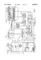
- FIG. 1is a block diagram of an MRI system which employs the present invention
- FIG. 2is an electrical block diagram of the transceiver which forms part of the MRI system of FIG. 1;
- FIG. 3is an illustration of the prior art which uses "scout" images and the prescribe process using three orthogonal previously acquired images.
- FIG. 4is an illustration of the prior art which depicts the reformat and intersection reference line process following data acquisition.
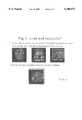
- FIG. 5illustrates an actual implementation of the present invention imaging a human head.
- FIG. 6illustrates the real-time updating of the section cross-references on the localizer images.
- FIG. 7illustrates the real-time control of the primary imaging plane using the cross-reference lines on the localizer images.
- FIG. 1there is shown the major components of a preferred MRI system which incorporates the present invention.
- the operation of the systemis controlled from an operator console 100 which includes an input device 101, a control panel 102 and a display 104.
- the console 100communicates through a link 116 with a separate computer system 107 that enables an operator to control the production and display of images on the screen 104.
- the computer system 107includes a number of modules which communicate with each other through a backplane. These include an image processor module 106, a CPU module 108 and a memory module 113, known in the art as a frame buffer for storing image data arrays.
- the computer system 107is linked to a disk storage 111 and a tape drive 112 for storage of image data and programs, and it communicates with a separate system control 122 through a high speed serial link 115.
- the system control 122includes a set of modules connected together by a backplane. These include a CPU module 119 and a pulse generator module 121 which connects to the operator console 100 through a serial link 125. It is through this link 125 that the system control 122 receives commands from the operator which indicate the scan sequence that is to be performed.
- the pulse generator module 121operates the system components to carry out the desired scan sequence. It produces data which indicates the timing, strength and shape of the RF pulses which are to be produced, and the timing of and length of the data acquisition window.
- the pulse generator module 121connects to a set of gradient amplifiers 127, to indicate the timing and shape of the gradient pulses to be produced during the scan.
- the pulse generator module 121also receives patient data from a physiological acquisition controller 129 that receives signals from a number of different sensors connected to the patient, such as ECG signals from electrodes or respiratory signals from a bellows. And finally, the pulse generator module 121 connects to a scan room interface circuit 133 which receives signals from various sensors associated with the condition of the patient and the magnet system. It is also through the scan room interface circuit 133 that a patient positioning system 134 receives commands to move the patient to the desired position for the scan.
- the gradient waveforms produced by the pulse generator module 121are applied to a gradient amplifier system 127 comprised of G x , G y and G z amplifiers.
- Each gradient amplifierexcites a corresponding gradient coil in an assembly generally designated 139 to produce the magnetic field gradients used for position encoding acquired signals.
- the gradient coil assembly 139forms part of a magnet assembly 141 which includes a polarizing magnet 140 and a whole-body RF coil 152.
- a transceiver module 150 in the system control 122produces pulses which are amplified by an RF amplifier 151 and coupled to the RF coil 152 by a transmit/receiver switch 154.
- the resulting signals radiated by the excited nuclei in the patientmay be sensed by the same RF coil 152 and coupled through the transmit/receive switch 154 to a preamplifier 153.
- the amplified NMR signalsare demodulated, filtered, and digitized in the receiver section of the transceiver 150.
- the transmit/receive switch 154is controlled by a signal from the pulse generator module 121 to electrically connect the RF amplifier 151 to the coil 152 during the transmit mode and to connect the preamplifier 153 during the receive mode.
- the transmit/receive switch 154also enables a separate RF coil (for example, a head coil or surface coil) to be used in either the transmit or receive mode.
- the NMR signals picked up by the RF coil 152are digitized by the transceiver module 150 and transferred to a memory module 160 in the system control 122.
- an array processor 161operates to Fourier transform the data into an array of image data.
- This image datais conveyed through the serial link 115 to the computer system 107 where it is stored in the disk memory 111.
- this image datamay be archived on the tape drive 112, or it may be further processed by the image processor 106 and conveyed to the operator console 100 and presented on the display 104.
- the transceiver 150produces the RF excitation field B 1 through power amplifier 151 at a coil 152A and receives the resulting signal induced in a coil 152B.
- the coils 152A and Bmay be separate as shown in FIG. 2, or they may be a single wholebody coil as shown in FIG. 1.
- the base, or carrier, frequency of the RF excitation fieldis produced under control of a frequency synthesizer 200 which receives a set of digital signals (CF) from the CPU module 119 and pulse generator module 121. These digital signals indicate the frequency and phase of the RF carrier signal produced at an output 201.
- CFdigital signals
- the commanded RF carrieris applied to a modulator and up converter 202 where its amplitude is modulated in response to a signal R(t) also received from the pulse generator module 121.
- the signal R(t)defines the envelope of the RF excitation pulse to be produced and is produced in the module 121 by sequentially reading out a series of stored digital values. These stored digital values may, in turn, be changed from the operator console 100 to enable any desired RF pulse envelope to be produced.
- the magnitude of the RF excitation pulse produced at output 205is attenuated by an exciter attenuator circuit 206 which receives a digital command, TA, from the backplane 118.
- the attenuated RF excitation pulsesare applied to the power amplifier 151 that drives the RF coil 152A.
- the NMR signal produced by the subjectis picked up by the receiver coil 152B and applied through the preamplifier 153 to the input of a receiver attenuator 207.
- the receiver attenuator 207further amplifies the signal by an amount determined by a digital attenuation signal (RA) received from the backplane 118.
- RAdigital attenuation signal
- the received signalis at or around the Larmor frequency, and this high frequency signal is down converted in a two step process by a down converter 208 which first mixes the NMR signal with the carrier signal on line 201 and then mixes the resulting difference signal with the 2.5 MHz reference signal on line 204.
- the down converted NMR signalis applied to the input of an analog-to-digital (A/D) converter 209 which samples and digitizes the analog signal and applies it to a digital detector and signal processor 210 which produces 16 bit in-phase (I) values and 16-bit quadrature (Q) values corresponding to the received signal.
- A/Danalog-to-digital
- the resulting stream of digitized I and Q values of the received signalare output through backplane 118 to the memory module 160 where they are normalized in accordance with the present invention and then employed to reconstruct an image.
- the 2.5 MHz reference signal as well as the 250 kHz sampling signal and the 5, 10 and 60 MHz reference signalsare produced by a reference frequency generator 203 from a common 20 MHz master clock signal.
- a reference frequency generator 203For a more detailed description of the receiver, reference is made to U.S. Pat. No. 4,992,736 which is incorporated herein by reference.
- an operatormaneuvers a two dimensional scan plane through the structure of interest, typically an anatomical structure such as the heart or head of a human being. Such maneuvering is accomplished from the operator console 100 using an input device 101.
- the input device 101is selected from a group including a mouse, a joystick, a keyboard, a track ball, a voice control, a touch screen and a light wand.
- the MR imaging system of the present inventionis capable of imaging in any desired orientation within the structure of interest and is equipped to perform both real-time acquisition or non-real-time acquisition of images.
- real-timerefers to continuous acquisition and reconstruction of MR image data as rapidly as it is acquired by the MRI system.
- a real-time MR imagecan be acquired, processed and displayed in approximately one second or less as limited by system performance.
- the real-time MRI systemlocalizes planar sections and imaging volumes of the structure of interest without the need for a preliminary data set.
- the present inventionprovides a method and apparatus for displaying the relative position of an imaging plane, also referred to as an acquisition plane, of a primary real-time image 304 of a structure positioned in an MRI system relative to mutually orthogonal views of such structure of interest.
- the structure of interestmay be and typically is an anatomical structure of a human body.
- FIG. 5illustrates an actual implementation of the present invention imaging a human head.
- an operatorinteractively acquires the primary, real-time image 304 of a planar section of the structure of interest and displaying such image on the display screen 104.
- the operatorthen initiates the acquisition of a first localizer data set from the same orientation as the primary real-time image 304 using the input device 101 which is then displayed as a first localizer image 307.
- a present inventionthen acquires a second localizer data set from an imaging section of the structure of interest which is orthogonal to the primary real-time image 304 which is then displayed as a second localizer image 309.
- the present inventionacquires a third localizer data set which is then displayed as an imaging section of the structure of interest which is orthogonal to the primary real-time image 304 and the second localizer data set which is then displayed as a third localizer image 311.
- the present inventiondisplays the first, second and third localizer images 307, 309 and 311 in corresponding three separate displays, 308, 310 and 312 on the display screen 104 with the image of the primary real-time image 304 of the structure of interest and provides a graphic cross-reference 316 on each of the displayed localizer images 307, 309 and 311 depicting the intersection of the primary real-time image 304 and each of the mutually orthogonal localizer images.
- Each of said localizer images 307, 309 and 311are replaceable as determined by the operator using the input device 101.
- the operatorselects and maneuvers the imaging section of the structure of interest by using an input device 101 selected from a group including a mouse, a joystick, a keyboard, a track ball, a voice control, a touch screen and a light wand.
- an input device 101selected from a group including a mouse, a joystick, a keyboard, a track ball, a voice control, a touch screen and a light wand.
- the operatorusing the input device, such as a mouse, "clicks" on a graphic user interface displayed on the display screen 104 which invokes routines on the CPU 108 in the computer system of the MRI system.
- the CPU 108then executes the instruction, calculating the desired image planar section, rotation and offset parameters and sends the appropriate parameters to the pulse generator 121 in the control system 122 of the MRI system.
- Each of said localizer images 307, 309 and 311are replaceable as determined by the operator using the input device 101.
- the present inventioncan then repeat the method of acquiring the three localizer data sets and the processing in the computer a plurality of times to produce a corresponding plurality of replaceable localizer images.
- the present inventionalso provides the operator with the ability to manipulate the graphic cross-reference 316 directly on any of the three localizer images 307, 309 and 311 displayed in the corresponding displays 308, 310 and 312 on the display screen 104.
- the present inventionthen automatically updates the position of the primary real-time image 304 as well as the graphic cross-reference 316 on the other localizer images.
- the present inventionallows the MRI system operator to see the relative position of the imaging plane of the structure of interest as depicted in the primary, real-time image 304 relative to the mutually orthogonal views of the localizer images 307, 309 and 311.
- the operatorusing the input device 101, may also select one of the three localizer images 307, 309 and 311 to cause such localizer image to then become the primary, real-time image.
- the computer system of the MRI systemthen updates the graphic cross-references on the localizer images displayed on the display screen 104 in real-time.
Landscapes
- Physics & Mathematics (AREA)
- Engineering & Computer Science (AREA)
- Signal Processing (AREA)
- High Energy & Nuclear Physics (AREA)
- Condensed Matter Physics & Semiconductors (AREA)
- General Physics & Mathematics (AREA)
- Magnetic Resonance Imaging Apparatus (AREA)
Abstract
Description
The field of the invention is nuclear magnetic resonance imaging methods and systems. More particularly, the invention relates to MRI imaging systems equipped for real-time imaging and methods for assisting the operator to interactively position the excitation profile for subsequent acquisition of the desired anatomical imaging section.
When a substance such as human tissue is subjected to a uniform magnetic field (polarizing field Bo), the individual magnetic moments of the spins in the tissue attempt to align with this polarizing field, but process about it in random order at their characteristic Larmor frequency. If the substance, or tissue, is subjected to a magnetic field (excitation field B1) which is the x-y plane and which is near the Larmor frequency, the net aligned moment, Mz, may be rotated, or "tipped", into the x-y plane to produce a net transverse magnetic moment M. A signal is emitted by the excited spins after the excitation signal B1 is terminated and this signal may be received and processed to form an image.
When utilizing these signals to produce images, magnetic field gradients (Gx, Gy and Gz) are employed. Typically, the region to be imaged is scanned by a sequence of measurement cycles in which these gradients vary according to the particular localization method being used. The resulting set of received NMR signals are digitized and processed to reconstruct the image using one of many well known reconstruction techniques.
When attempting to define the volume of coverage for an MRI scan, the NMR system operator may desire to prescribe a specific two dimension scan plane within the total volume of coverage. This process can be particularly useful when prescribing a double oblique, off axis two dimensional scan plane of complex anatomy such as vasculature.
Typically, an operator must first acquire an axial, sagittal or coronal "scout" image of the structure of interest. Such scout image is then displayed and the operator uses such scout image to graphically prescribe the 2D section or 3D imaging volume. Three-plane localizer acquisitions have been developed which quickly acquire standard orthogonal scout images and then display such images with graphic prescription overlay tools. Such procedure allows the operator to rapidly prescribe subsequent acquisition imaging volumes of the structure of interest. FIG. 3 depicts the prior art which uses scout images and prescribe process using those orthogonal planes.
Following data acquisition the MR system reformats the previously acquired volume data set. Such reformatting is accomplished by pixel data post-processing. Such reformatted volume data set is used to display a particular projection or image plane, a reference image or a set of orthogonal reference images as determined by the operator. Such image is usually displayed with an intersection reference line. The intersection reference line is updated to reflect the position of the projection or visualization plane of the image of the structure of interest. FIG. 4 depicts the prior art process of such reformat and intersection reference line display which is performed following data acquisition.
In accordance with the present invention, Applicant provides a method and apparatus for producing an imaging plane on a primary, real-time image of a structure positioned in a MRI system having a display screen and an input device. An operator interactively acquires the primary, real-time image of a planar section of the structure of interest, such as an anatomical structure. Using an input device, the operator initiates the acquisition of a first localizer data set from the same orientation as the primary, real-time image of the structure under study. The present invention then acquires such data as a first localizer image and displays such image along side the primary, real-time image on a display screen of the MRI system. The present invention then acquires second and third localizer data sets which are orthogonal to the primary, real-time image and to each other and generating and displays said second and third localizer images. All three localizer images are displayed in three separate displays along side the primary, real-time image of the structure of interest with each localizer image having a graphic, cross-reference, typically a line, which depicts the intersection of the primary, real-time image in each of the mutually orthogonal localizer images. The operator of the present invention may then see the relative position of the primary, real-time image plane relative to the mutually orthogonal views of such structure of interest.
A principal feature of the present invention is the ability to update the mutually orthogonal views of the structure of interest at any time during the real-time scanning process.
Another important feature of the present invention is the real-time coupling between the graphic cross-reference on each of the localizer images with the primary, real-time image of the structure of interest.
Another important feature of the present invention is the ability to select one of the three localizer images and thereby causing such localizer image to become the then current primary, real-time image of the structure of interest.
A further object of the present invention is the ability to manipulate the graphic cross-reference directly on any of the three localizer images with a corresponding update of the primary, real-time image geometry and graphic cross-reference on the other two localizer images.
It is an additional object of the present invention to rapidly localize views on an image of a structure of interest displayed on a screen of a MRI system. Other principal features and advantages of the present invention will become apparent to those skilled in the art upon review of the following drawings, the detailed description and the appended claims.
FIG. 1 is a block diagram of an MRI system which employs the present invention;
FIG. 2 is an electrical block diagram of the transceiver which forms part of the MRI system of FIG. 1;
FIG. 3 is an illustration of the prior art which uses "scout" images and the prescribe process using three orthogonal previously acquired images.
FIG. 4 is an illustration of the prior art which depicts the reformat and intersection reference line process following data acquisition.
FIG. 5 illustrates an actual implementation of the present invention imaging a human head.
FIG. 6 illustrates the real-time updating of the section cross-references on the localizer images.
FIG. 7 illustrates the real-time control of the primary imaging plane using the cross-reference lines on the localizer images.
Before explaining the preferred embodiment of the invention in detail it is to be understood that the invention is not limited in its application to the details of construction and the arrangement of the components set forth in the following description as illustrated in the drawings. The invention is capable of other embodiments or being practiced or carried out in various ways. Also, it is to be understood that the phraseology and terminology employed herein is for the purpose of description and should not be regarded as limiting.
Referring first to FIG. 1, there is shown the major components of a preferred MRI system which incorporates the present invention. The operation of the system is controlled from anoperator console 100 which includes aninput device 101, acontrol panel 102 and adisplay 104. Theconsole 100 communicates through alink 116 with aseparate computer system 107 that enables an operator to control the production and display of images on thescreen 104. Thecomputer system 107 includes a number of modules which communicate with each other through a backplane. These include animage processor module 106, aCPU module 108 and amemory module 113, known in the art as a frame buffer for storing image data arrays. Thecomputer system 107 is linked to adisk storage 111 and atape drive 112 for storage of image data and programs, and it communicates with aseparate system control 122 through a highspeed serial link 115.
Thesystem control 122 includes a set of modules connected together by a backplane. These include aCPU module 119 and apulse generator module 121 which connects to theoperator console 100 through aserial link 125. It is through thislink 125 that thesystem control 122 receives commands from the operator which indicate the scan sequence that is to be performed. Thepulse generator module 121 operates the system components to carry out the desired scan sequence. It produces data which indicates the timing, strength and shape of the RF pulses which are to be produced, and the timing of and length of the data acquisition window. Thepulse generator module 121 connects to a set ofgradient amplifiers 127, to indicate the timing and shape of the gradient pulses to be produced during the scan. Thepulse generator module 121 also receives patient data from aphysiological acquisition controller 129 that receives signals from a number of different sensors connected to the patient, such as ECG signals from electrodes or respiratory signals from a bellows. And finally, thepulse generator module 121 connects to a scanroom interface circuit 133 which receives signals from various sensors associated with the condition of the patient and the magnet system. It is also through the scanroom interface circuit 133 that apatient positioning system 134 receives commands to move the patient to the desired position for the scan.
The gradient waveforms produced by thepulse generator module 121 are applied to agradient amplifier system 127 comprised of Gx, Gy and Gz amplifiers. Each gradient amplifier excites a corresponding gradient coil in an assembly generally designated 139 to produce the magnetic field gradients used for position encoding acquired signals. Thegradient coil assembly 139 forms part of amagnet assembly 141 which includes apolarizing magnet 140 and a whole-body RF coil 152.
Atransceiver module 150 in thesystem control 122 produces pulses which are amplified by anRF amplifier 151 and coupled to theRF coil 152 by a transmit/receiver switch 154. The resulting signals radiated by the excited nuclei in the patient may be sensed by thesame RF coil 152 and coupled through the transmit/receiveswitch 154 to apreamplifier 153. The amplified NMR signals are demodulated, filtered, and digitized in the receiver section of thetransceiver 150. The transmit/receiveswitch 154 is controlled by a signal from thepulse generator module 121 to electrically connect theRF amplifier 151 to thecoil 152 during the transmit mode and to connect thepreamplifier 153 during the receive mode. The transmit/receiveswitch 154 also enables a separate RF coil (for example, a head coil or surface coil) to be used in either the transmit or receive mode.
The NMR signals picked up by theRF coil 152 are digitized by thetransceiver module 150 and transferred to amemory module 160 in thesystem control 122. When the scan is completed and an entire array of data has been acquired in thememory module 160, anarray processor 161 operates to Fourier transform the data into an array of image data. This image data is conveyed through theserial link 115 to thecomputer system 107 where it is stored in thedisk memory 111. In response to commands received from theoperator console 100, this image data may be archived on thetape drive 112, or it may be further processed by theimage processor 106 and conveyed to theoperator console 100 and presented on thedisplay 104.
Referring particularly to FIGS. 1 and 2, thetransceiver 150 produces the RF excitation field B1 throughpower amplifier 151 at acoil 152A and receives the resulting signal induced in acoil 152B. As indicated above, thecoils 152A and B may be separate as shown in FIG. 2, or they may be a single wholebody coil as shown in FIG. 1. The base, or carrier, frequency of the RF excitation field is produced under control of afrequency synthesizer 200 which receives a set of digital signals (CF) from theCPU module 119 andpulse generator module 121. These digital signals indicate the frequency and phase of the RF carrier signal produced at anoutput 201. The commanded RF carrier is applied to a modulator and upconverter 202 where its amplitude is modulated in response to a signal R(t) also received from thepulse generator module 121. The signal R(t) defines the envelope of the RF excitation pulse to be produced and is produced in themodule 121 by sequentially reading out a series of stored digital values. These stored digital values may, in turn, be changed from theoperator console 100 to enable any desired RF pulse envelope to be produced.
The magnitude of the RF excitation pulse produced atoutput 205 is attenuated by anexciter attenuator circuit 206 which receives a digital command, TA, from thebackplane 118. The attenuated RF excitation pulses are applied to thepower amplifier 151 that drives theRF coil 152A. For a more detailed description of this portion of thetransceiver 122, reference is made to U.S. Pat. No. 4,952,877 which is incorporated herein by reference.
Referring still to FIGS. 1 and 2 the NMR signal produced by the subject is picked up by thereceiver coil 152B and applied through thepreamplifier 153 to the input of areceiver attenuator 207. Thereceiver attenuator 207 further amplifies the signal by an amount determined by a digital attenuation signal (RA) received from thebackplane 118.
The received signal is at or around the Larmor frequency, and this high frequency signal is down converted in a two step process by adown converter 208 which first mixes the NMR signal with the carrier signal online 201 and then mixes the resulting difference signal with the 2.5 MHz reference signal online 204. The down converted NMR signal is applied to the input of an analog-to-digital (A/D)converter 209 which samples and digitizes the analog signal and applies it to a digital detector andsignal processor 210 which produces 16 bit in-phase (I) values and 16-bit quadrature (Q) values corresponding to the received signal. The resulting stream of digitized I and Q values of the received signal are output throughbackplane 118 to thememory module 160 where they are normalized in accordance with the present invention and then employed to reconstruct an image.
The 2.5 MHz reference signal as well as the 250 kHz sampling signal and the 5, 10 and 60 MHz reference signals are produced by areference frequency generator 203 from a common 20 MHz master clock signal. For a more detailed description of the receiver, reference is made to U.S. Pat. No. 4,992,736 which is incorporated herein by reference.
To practice the present invention, an operator maneuvers a two dimensional scan plane through the structure of interest, typically an anatomical structure such as the heart or head of a human being. Such maneuvering is accomplished from theoperator console 100 using aninput device 101. Theinput device 101 is selected from a group including a mouse, a joystick, a keyboard, a track ball, a voice control, a touch screen and a light wand. The MR imaging system of the present invention is capable of imaging in any desired orientation within the structure of interest and is equipped to perform both real-time acquisition or non-real-time acquisition of images. In particular, real-time refers to continuous acquisition and reconstruction of MR image data as rapidly as it is acquired by the MRI system. A real-time MR image can be acquired, processed and displayed in approximately one second or less as limited by system performance. The real-time MRI system localizes planar sections and imaging volumes of the structure of interest without the need for a preliminary data set.
The present invention provides a method and apparatus for displaying the relative position of an imaging plane, also referred to as an acquisition plane, of a primary real-time image 304 of a structure positioned in an MRI system relative to mutually orthogonal views of such structure of interest. The structure of interest may be and typically is an anatomical structure of a human body. FIG. 5 illustrates an actual implementation of the present invention imaging a human head.
Referring now to FIGS. 5, 6 and 7, an operator interactively acquires the primary, real-time image 304 of a planar section of the structure of interest and displaying such image on thedisplay screen 104. The operator then initiates the acquisition of a first localizer data set from the same orientation as the primary real-time image 304 using theinput device 101 which is then displayed as afirst localizer image 307. A present invention then acquires a second localizer data set from an imaging section of the structure of interest which is orthogonal to the primary real-time image 304 which is then displayed as asecond localizer image 309. And finally, the present invention acquires a third localizer data set which is then displayed as an imaging section of the structure of interest which is orthogonal to the primary real-time image 304 and the second localizer data set which is then displayed as a thirdlocalizer image 311. The present invention displays the first, second andthird localizer images display screen 104 with the image of the primary real-time image 304 of the structure of interest and provides agraphic cross-reference 316 on each of the displayedlocalizer images time image 304 and each of the mutually orthogonal localizer images. Each of saidlocalizer images input device 101. The operator selects and maneuvers the imaging section of the structure of interest by using aninput device 101 selected from a group including a mouse, a joystick, a keyboard, a track ball, a voice control, a touch screen and a light wand. In a typical operation, the operator, using the input device, such as a mouse, "clicks" on a graphic user interface displayed on thedisplay screen 104 which invokes routines on theCPU 108 in the computer system of the MRI system. TheCPU 108 then executes the instruction, calculating the desired image planar section, rotation and offset parameters and sends the appropriate parameters to thepulse generator 121 in thecontrol system 122 of the MRI system. Each of saidlocalizer images input device 101. The present invention can then repeat the method of acquiring the three localizer data sets and the processing in the computer a plurality of times to produce a corresponding plurality of replaceable localizer images.
The present invention also provides the operator with the ability to manipulate thegraphic cross-reference 316 directly on any of the threelocalizer images displays display screen 104. The present invention then automatically updates the position of the primary real-time image 304 as well as thegraphic cross-reference 316 on the other localizer images. The present invention allows the MRI system operator to see the relative position of the imaging plane of the structure of interest as depicted in the primary, real-time image 304 relative to the mutually orthogonal views of thelocalizer images
The operator, using theinput device 101, may also select one of the threelocalizer images display screen 104 in real-time.
An important distinction between the present invention and the prior art is that all of the images, the threelocalizer images time image 304, are generated in real-time and thegraphic cross-reference 316 displayed on each of the image displays 308, 310 and 312 are updated in real-time to reflect the geometry of the primary, real-time image 304 under control of the operator at theoperator console 100. The present invention provides real-time coupling between thegraphic cross-reference 316 and the primary, real-time image being acquired by the MRI system.
Thus, it should be apparent that there has been provided in accordance with the present invention a method and apparatus for producing a real-time MR section graphic cross-reference on replaceable MR localizer images on an image section of a structure of interest positioned in a MRI system that satisfies the objectives and advantages set forth above. Although the invention has been described in conjunction with specific embodiments thereof, it is evident that alternatives, modifications and variations will be apparent to those ordinarily skilled in the art. Accordingly, it is intended to embrace all such alternatives, modifications and variations that fall within the spirit and scope of the appended claims.
Claims (13)
1. A method for producing an indication of an imaging plane of a primary, real-time image of a structure positioned in a MRI system having a display screen, the steps comprising:
(a) interactively acquiring the primary, real-time image of a planar section of the structure of interest and displaying such image on the display screen;
(b) acquiring a first localizer data set from the same orientation as the primary real-time image and displaying such data as a first localizer image;
(c) acquiring a second localizer data set from an imaging section of the structure of interest which is orthogonal to the primary, real-time image and displaying such data set as a second localizer image;
(d) acquiring a third localizer data set from an imaging section of the structure of interest which is orthogonal to the primary, real-time image and the second localizer data set and displaying such third localizer data set as a third localizer image;
(e) displaying the first, second, and third localizer images in corresponding three separate displays on the display screen with the image of the primary, real-time image of the structure of interest; and
(f) providing a graphic cross-reference on each of the displayed localizer images depicting the intersection of the primary, real-time image and each of the mutually orthogonal localizer images.
2. The method as recited in claim 1, including the steps of updating the graphic cross-reference on each of said localizer images in real-time as the primary, real-time image of the structure of interest is maneuvered to a new orientation and positioned on the display screen.
3. The method as recited in claim 1, in which the steps of (b) through (f), inclusive, are repeated a plurality of times to produce a corresponding plurality of localizer images.
4. The method as recited in claim 1, wherein the structure of interest is an anatomical structure.
5. The method of claim 1, including the step of manipulating the graphic cross-reference directly on any of the three localizer images with a corresponding update of the primary, real-time image and the graphic cross-references on the other two localizer images.
6. The method of claim 1, including the step of selecting one of the three localizer images and directly causing such localizer image to become the primary, real-time image.
7. The method as recited in claim 1, wherein the steps of (b), (c) and (d) are performed by an input device selected from a group consisting of a mouse, a joystick, a keyboard, a track ball, a voice control, a touch screen and a light wand.
8. An apparatus for producing an indication of an imaging plane of a primary, real-time image of a structure positioned in a MRI system having a display screen, the apparatus comprising:
(a) a means for interactively acquiring the primary, real-time image of a planar section of the structure of interest and displaying such image on the display screen;
(b) a means for acquiring a first localizer data set from the same orientation as the primary real-time image and displaying such data as a first localizer image;
(c) a means for acquiring a second localizer data set from an imaging section of the structure of interest which is orthogonal to the primary, real-time image and displaying such data set as a second localizer image;
(d) a means for acquiring a third localizer data set from an imaging section of the structure of interest which is orthogonal to the primary, real-time image and the second localizer data set and displaying such third localizer data set as a third localizer image;
(e) a means for displaying the first, second, and third localizer images in corresponding three separate displays on the display screen with the image of the primary, real-time image of the structure of interest; and
(f) a means for providing a graphic cross-reference on each of the displayed localizer images depicting the intersection of the primary, real-time image and each of the mutually orthogonal localizer images.
9. The apparatus as recited in claim 8, including a means for updating the graphic cross-reference on each of said localizer images in real-time as the primary, real-time image of the structure of interest is maneuvered to a new orientation and positioned on the display screen.
10. The apparatus as recited in claim 8, wherein the structure of interest is an anatomical structure.
11. The apparatus of claim 8, including a means for manipulating the graphic cross-reference directly on any of the three localizer images with a corresponding update of the primary, real-time image and the graphic cross-references on the other two localizer images.
12. The apparatus of claim 8, including a means for selecting one of the three localizer images and directly causing such localizer image to become the primary, real-time image.
13. The apparatus as recited in claim 8, further comprising a means for initiating acquisition of the localizer data sets, wherein the means for initiating acquisition comprises an input device selected from a group consisting of a mouse, a joystick, a keyboard, a track ball, a voice control, a touch screen and a light wand.
Priority Applications (1)
| Application Number | Priority Date | Filing Date | Title |
|---|---|---|---|
| US09/199,687US6108573A (en) | 1998-11-25 | 1998-11-25 | Real-time MR section cross-reference on replaceable MR localizer images |
Applications Claiming Priority (1)
| Application Number | Priority Date | Filing Date | Title |
|---|---|---|---|
| US09/199,687US6108573A (en) | 1998-11-25 | 1998-11-25 | Real-time MR section cross-reference on replaceable MR localizer images |
Publications (1)
| Publication Number | Publication Date |
|---|---|
| US6108573Atrue US6108573A (en) | 2000-08-22 |
Family
ID=22738594
Family Applications (1)
| Application Number | Title | Priority Date | Filing Date |
|---|---|---|---|
| US09/199,687Expired - LifetimeUS6108573A (en) | 1998-11-25 | 1998-11-25 | Real-time MR section cross-reference on replaceable MR localizer images |
Country Status (1)
| Country | Link |
|---|---|
| US (1) | US6108573A (en) |
Cited By (54)
| Publication number | Priority date | Publication date | Assignee | Title |
|---|---|---|---|---|
| US6301497B1 (en)* | 1999-07-12 | 2001-10-09 | Ge Medical Systems Global Technology Company, Llc | Method and apparatus for magnetic resonance imaging intersecting slices |
| US20010040589A1 (en)* | 2000-03-09 | 2001-11-15 | De Bliek Hubrecht Lambertus Tjalling | User interface for the processing and presentation of image data |
| US6331776B1 (en) | 1998-11-25 | 2001-12-18 | General Electric Company | MR imaging system with interactive MR geometry prescription control over a network |
| US6400157B1 (en)* | 1997-11-26 | 2002-06-04 | Fonar Corporation | MRI methods and systems |
| US20020077864A1 (en)* | 2000-11-17 | 2002-06-20 | Samuel Cavallaro | Fully integrated critical care workstation |
| US6484048B1 (en) | 1998-10-21 | 2002-11-19 | Kabushiki Kaisha Toshiba | Real-time interactive three-dimensional locating and displaying system |
| US20020176637A1 (en)* | 2001-01-23 | 2002-11-28 | Cyril Allouche | Image processing method of following the deformation of an organ which is deformable over time |
| EP1220154A3 (en)* | 2000-12-27 | 2004-04-14 | GE Medical Systems Global Technology Company LLC | Magnetic resonance imaging method and system |
| EP1220153A3 (en)* | 2000-12-29 | 2005-01-19 | GE Medical Systems Global Technology Company LLC | Methods and apparatus for generating a scout image |
| US20050033158A1 (en)* | 2001-08-24 | 2005-02-10 | Vu Anthony T. | Real-time localization monitoring, triggering, and acquisition of 3D MRI |
| US20050038975A1 (en)* | 2000-12-29 | 2005-02-17 | Mips Technologies, Inc. | Configurable co-processor interface |
| US20050165300A1 (en)* | 2002-03-19 | 2005-07-28 | Haselhoff Eltjo H. | Method software and apparatus for acquiring mr-image data pertaining to a moving organ |
| US20050180540A1 (en)* | 2004-02-16 | 2005-08-18 | Go Mukumoto | X-ray computed tomographic apparatus and image processing apparatus |
| WO2005093451A1 (en)* | 2004-03-26 | 2005-10-06 | Koninklijke Philips Electronics N.V. | Non-expert control of an mr system |
| US20060013462A1 (en)* | 2004-07-15 | 2006-01-19 | Navid Sadikali | Image display system and method |
| US20060056674A1 (en)* | 2004-09-07 | 2006-03-16 | Sari Lehtonen-Krause | Method and magnetic resonance system for generation of localizer slice images of an examination volume of a subject |
| WO2005088328A3 (en)* | 2004-03-01 | 2006-03-30 | Koninkl Philips Electronics Nv | All in one plan scan imaging for optimization of acquisition parameters |
| US20060079760A1 (en)* | 2004-09-06 | 2006-04-13 | Sari Lehtonen-Krause | MR method and apparatus for determining coronal and sagittal image planes from an image data set of a shoulder joint |
| US20060169809A1 (en)* | 2005-01-31 | 2006-08-03 | M-I L.L.C. | Method and system for harvesting weighting agent fines |
| US20070191703A1 (en)* | 2006-02-15 | 2007-08-16 | Gudrun Graf | Method and apparatus for acquisition of magnetic resonance slice images of a subject |
| US20070252836A1 (en)* | 2006-04-28 | 2007-11-01 | General Electric Company | Region of interest selector |
| CN100382762C (en)* | 2004-08-05 | 2008-04-23 | 株式会社东芝 | Image processing device and image processing method |
| US20080119723A1 (en)* | 2006-11-22 | 2008-05-22 | Rainer Wegenkittl | Localizer Display System and Method |
| WO2008084232A1 (en)* | 2007-01-10 | 2008-07-17 | Cambridge Enterprise Limited | Apparatus and method for acquiring sectional images |
| US7408348B1 (en) | 2001-07-19 | 2008-08-05 | Fonar Corporation | Hand operated device for controlling characteristics of an MRI image, and the like |
| US20080218533A1 (en)* | 2007-03-06 | 2008-09-11 | Casio Hitachi Mobile Communications Co., Ltd. | Terminal apparatus and processing program thereof |
| US20090087053A1 (en)* | 2007-09-27 | 2009-04-02 | General Electric Company | Systems and Methods for Image Processing of 2D Medical Images |
| US20090086912A1 (en)* | 2007-09-28 | 2009-04-02 | Takuya Sakaguchi | Image display apparatus and x-ray diagnostic apparatus |
| US20100131890A1 (en)* | 2008-11-25 | 2010-05-27 | General Electric Company | Zero pixel travel systems and methods of use |
| US8271067B1 (en)* | 2003-10-17 | 2012-09-18 | General Electric Company | Method and apparatus to graphically display a pre-scan volume on a localizer image |
| US20160047872A1 (en)* | 2014-08-14 | 2016-02-18 | Samsung Electronics Co., Ltd. | Magnetic resonance imaging apparatus and method of generating magnetic resonance image |
| US20200151226A1 (en)* | 2018-11-14 | 2020-05-14 | Wix.Com Ltd. | System and method for creation and handling of configurable applications for website building systems |
| US10884593B1 (en)* | 2019-11-26 | 2021-01-05 | GE Precision Healthcare LLC | Systems and methods for remote layout control of medical image viewers |
| US20210166339A1 (en)* | 2019-11-18 | 2021-06-03 | Monday.Com | Digital processing systems and methods for cell animations within tables of collaborative work systems |
| US20220300666A1 (en)* | 2021-03-17 | 2022-09-22 | Kyocera Document Solutions Inc. | Electronic apparatus and image forming apparatus |
| US11587039B2 (en) | 2020-05-01 | 2023-02-21 | Monday.com Ltd. | Digital processing systems and methods for communications triggering table entries in collaborative work systems |
| US11687216B2 (en) | 2021-01-14 | 2023-06-27 | Monday.com Ltd. | Digital processing systems and methods for dynamically updating documents with data from linked files in collaborative work systems |
| US11698890B2 (en) | 2018-07-04 | 2023-07-11 | Monday.com Ltd. | System and method for generating a column-oriented data structure repository for columns of single data types |
| US11741071B1 (en) | 2022-12-28 | 2023-08-29 | Monday.com Ltd. | Digital processing systems and methods for navigating and viewing displayed content |
| US11829953B1 (en) | 2020-05-01 | 2023-11-28 | Monday.com Ltd. | Digital processing systems and methods for managing sprints using linked electronic boards |
| US20230409353A1 (en)* | 2022-06-17 | 2023-12-21 | OneTrust, LLC | Dynamic generation of graphical user interfaces for retrieving data from multiple computing systems |
| US11886683B1 (en) | 2022-12-30 | 2024-01-30 | Monday.com Ltd | Digital processing systems and methods for presenting board graphics |
| US11893381B1 (en) | 2023-02-21 | 2024-02-06 | Monday.com Ltd | Digital processing systems and methods for reducing file bundle sizes |
| US20240184423A1 (en)* | 2018-10-29 | 2024-06-06 | State Farm Mutual Automobile Insurance Company | Dynamic data-driven consolidation of user interface interactions requesting roadside assistance |
| US12014138B2 (en) | 2020-01-15 | 2024-06-18 | Monday.com Ltd. | Digital processing systems and methods for graphical dynamic table gauges in collaborative work systems |
| US12020210B2 (en) | 2020-02-12 | 2024-06-25 | Monday.com Ltd. | Digital processing systems and methods for table information displayed in and accessible via calendar in collaborative work systems |
| US12056664B2 (en) | 2021-08-17 | 2024-08-06 | Monday.com Ltd. | Digital processing systems and methods for external events trigger automatic text-based document alterations in collaborative work systems |
| US12056255B1 (en) | 2023-11-28 | 2024-08-06 | Monday.com Ltd. | Digital processing systems and methods for facilitating the development and implementation of applications in conjunction with a serverless environment |
| US12105948B2 (en) | 2021-10-29 | 2024-10-01 | Monday.com Ltd. | Digital processing systems and methods for display navigation mini maps |
| US12141722B2 (en) | 2019-11-18 | 2024-11-12 | Monday.Com | Digital processing systems and methods for mechanisms for sharing responsibility in collaborative work systems |
| US12169802B1 (en) | 2023-11-28 | 2024-12-17 | Monday.com Ltd. | Digital processing systems and methods for managing workflows |
| US12321421B2 (en)* | 2020-05-20 | 2025-06-03 | State Farm Mutual Automobile Insurance Company | Providing a GUI to enable analysis of time-synchronized data sets pertaining to a road segment |
| US12353419B2 (en) | 2018-07-23 | 2025-07-08 | Monday.com Ltd. | System and method for generating a tagged column-oriented data structure |
| US12379835B2 (en) | 2023-06-13 | 2025-08-05 | Monday.com Ltd. | Digital processing systems and methods for enhanced data representation |
Citations (2)
| Publication number | Priority date | Publication date | Assignee | Title |
|---|---|---|---|---|
| US5501218A (en)* | 1991-10-30 | 1996-03-26 | Kabushiki Kaisha Toshiba | Method of scanning in MRI |
| US6016438A (en)* | 1996-10-21 | 2000-01-18 | Kabushiki Kaisha Toshiba | MPR image creating apparatus and coaxial tomogram creating method therein |
- 1998
- 1998-11-25USUS09/199,687patent/US6108573A/ennot_activeExpired - Lifetime
Patent Citations (2)
| Publication number | Priority date | Publication date | Assignee | Title |
|---|---|---|---|---|
| US5501218A (en)* | 1991-10-30 | 1996-03-26 | Kabushiki Kaisha Toshiba | Method of scanning in MRI |
| US6016438A (en)* | 1996-10-21 | 2000-01-18 | Kabushiki Kaisha Toshiba | MPR image creating apparatus and coaxial tomogram creating method therein |
Cited By (96)
| Publication number | Priority date | Publication date | Assignee | Title |
|---|---|---|---|---|
| US6400157B1 (en)* | 1997-11-26 | 2002-06-04 | Fonar Corporation | MRI methods and systems |
| US6484048B1 (en) | 1998-10-21 | 2002-11-19 | Kabushiki Kaisha Toshiba | Real-time interactive three-dimensional locating and displaying system |
| US6492812B1 (en) | 1998-11-25 | 2002-12-10 | General Electric Company | MR imaging system with interactive MR geometry prescription control over a network |
| US6522141B2 (en)* | 1998-11-25 | 2003-02-18 | General Electric Company | MR imaging system with interactive MR geometry prescription control |
| US6331776B1 (en) | 1998-11-25 | 2001-12-18 | General Electric Company | MR imaging system with interactive MR geometry prescription control over a network |
| US6396266B1 (en)* | 1998-11-25 | 2002-05-28 | General Electric Company | MR imaging system with interactive MR geometry prescription control |
| US6301497B1 (en)* | 1999-07-12 | 2001-10-09 | Ge Medical Systems Global Technology Company, Llc | Method and apparatus for magnetic resonance imaging intersecting slices |
| US20010040589A1 (en)* | 2000-03-09 | 2001-11-15 | De Bliek Hubrecht Lambertus Tjalling | User interface for the processing and presentation of image data |
| US20020077864A1 (en)* | 2000-11-17 | 2002-06-20 | Samuel Cavallaro | Fully integrated critical care workstation |
| EP1220154A3 (en)* | 2000-12-27 | 2004-04-14 | GE Medical Systems Global Technology Company LLC | Magnetic resonance imaging method and system |
| US6844884B2 (en)* | 2000-12-27 | 2005-01-18 | Ge Medical Systems Global Technology Company, Llc | Multi-plane graphic prescription interface and method |
| EP1220153A3 (en)* | 2000-12-29 | 2005-01-19 | GE Medical Systems Global Technology Company LLC | Methods and apparatus for generating a scout image |
| US20050038975A1 (en)* | 2000-12-29 | 2005-02-17 | Mips Technologies, Inc. | Configurable co-processor interface |
| US20020176637A1 (en)* | 2001-01-23 | 2002-11-28 | Cyril Allouche | Image processing method of following the deformation of an organ which is deformable over time |
| US7408348B1 (en) | 2001-07-19 | 2008-08-05 | Fonar Corporation | Hand operated device for controlling characteristics of an MRI image, and the like |
| US6968225B2 (en) | 2001-08-24 | 2005-11-22 | General Electric Company | Real-time localization, monitoring, triggering and acquisition of 3D MRI |
| US20050033158A1 (en)* | 2001-08-24 | 2005-02-10 | Vu Anthony T. | Real-time localization monitoring, triggering, and acquisition of 3D MRI |
| US7383075B2 (en) | 2001-08-24 | 2008-06-03 | General Electric Company | Real-time localization monitoring, triggering, and acquisition of 3D MRI |
| US7418288B2 (en)* | 2002-03-19 | 2008-08-26 | Koninklijke Philips Electronics N.V. | Method software and apparatus for acquiring MR-image data pertaining to a moving organ |
| US20050165300A1 (en)* | 2002-03-19 | 2005-07-28 | Haselhoff Eltjo H. | Method software and apparatus for acquiring mr-image data pertaining to a moving organ |
| US8271067B1 (en)* | 2003-10-17 | 2012-09-18 | General Electric Company | Method and apparatus to graphically display a pre-scan volume on a localizer image |
| US7668285B2 (en)* | 2004-02-16 | 2010-02-23 | Kabushiki Kaisha Toshiba | X-ray computed tomographic apparatus and image processing apparatus |
| US20050180540A1 (en)* | 2004-02-16 | 2005-08-18 | Go Mukumoto | X-ray computed tomographic apparatus and image processing apparatus |
| US20070276220A1 (en)* | 2004-03-01 | 2007-11-29 | Koninklijke Philips Electronics N.V. | All in one plan scan imaging for optimization of acquisition parameters |
| WO2005088328A3 (en)* | 2004-03-01 | 2006-03-30 | Koninkl Philips Electronics Nv | All in one plan scan imaging for optimization of acquisition parameters |
| US7715899B2 (en) | 2004-03-01 | 2010-05-11 | Koninklijke Philips Electronics N.V. | All in one plan scan imaging for optimization of acquisition parameters |
| US20070208248A1 (en)* | 2004-03-26 | 2007-09-06 | Koninklijke Philips Electronics N.V. | Non-expert control of an mr system |
| WO2005093451A1 (en)* | 2004-03-26 | 2005-10-06 | Koninklijke Philips Electronics N.V. | Non-expert control of an mr system |
| US20060013462A1 (en)* | 2004-07-15 | 2006-01-19 | Navid Sadikali | Image display system and method |
| CN100382762C (en)* | 2004-08-05 | 2008-04-23 | 株式会社东芝 | Image processing device and image processing method |
| US20060079760A1 (en)* | 2004-09-06 | 2006-04-13 | Sari Lehtonen-Krause | MR method and apparatus for determining coronal and sagittal image planes from an image data set of a shoulder joint |
| US20060056674A1 (en)* | 2004-09-07 | 2006-03-16 | Sari Lehtonen-Krause | Method and magnetic resonance system for generation of localizer slice images of an examination volume of a subject |
| US7474912B2 (en)* | 2004-09-07 | 2009-01-06 | Siemens Aktiengesellschaft | Method and magnetic resonance system for generation of localizer slice images of an examination volume of a subject |
| US20060169809A1 (en)* | 2005-01-31 | 2006-08-03 | M-I L.L.C. | Method and system for harvesting weighting agent fines |
| US8620403B2 (en)* | 2006-02-15 | 2013-12-31 | Siemens Aktiengesellschaft | Method and apparatus for acquisition of magnetic resonance slice images of a subject |
| US20070191703A1 (en)* | 2006-02-15 | 2007-08-16 | Gudrun Graf | Method and apparatus for acquisition of magnetic resonance slice images of a subject |
| US20070252836A1 (en)* | 2006-04-28 | 2007-11-01 | General Electric Company | Region of interest selector |
| US20080119723A1 (en)* | 2006-11-22 | 2008-05-22 | Rainer Wegenkittl | Localizer Display System and Method |
| WO2008084232A1 (en)* | 2007-01-10 | 2008-07-17 | Cambridge Enterprise Limited | Apparatus and method for acquiring sectional images |
| US20100046695A1 (en)* | 2007-01-10 | 2010-02-25 | Cambridge Enterprise Limited | Apparatus and method for acquiring sectional images |
| US8576980B2 (en) | 2007-01-10 | 2013-11-05 | Cambridge Enterprise Limited | Apparatus and method for acquiring sectional images |
| US8819580B2 (en)* | 2007-03-06 | 2014-08-26 | Nec Corporation | Terminal apparatus and processing program thereof |
| US20080218533A1 (en)* | 2007-03-06 | 2008-09-11 | Casio Hitachi Mobile Communications Co., Ltd. | Terminal apparatus and processing program thereof |
| US20090087053A1 (en)* | 2007-09-27 | 2009-04-02 | General Electric Company | Systems and Methods for Image Processing of 2D Medical Images |
| US8009891B2 (en)* | 2007-09-27 | 2011-08-30 | General Electric Company | Systems and methods for image processing of 2D medical images |
| US8934604B2 (en)* | 2007-09-28 | 2015-01-13 | Kabushiki Kaisha Toshiba | Image display apparatus and X-ray diagnostic apparatus |
| US20090086912A1 (en)* | 2007-09-28 | 2009-04-02 | Takuya Sakaguchi | Image display apparatus and x-ray diagnostic apparatus |
| US20100131890A1 (en)* | 2008-11-25 | 2010-05-27 | General Electric Company | Zero pixel travel systems and methods of use |
| US8601385B2 (en)* | 2008-11-25 | 2013-12-03 | General Electric Company | Zero pixel travel systems and methods of use |
| US20160047872A1 (en)* | 2014-08-14 | 2016-02-18 | Samsung Electronics Co., Ltd. | Magnetic resonance imaging apparatus and method of generating magnetic resonance image |
| WO2016024784A1 (en)* | 2014-08-14 | 2016-02-18 | Samsung Electronics Co., Ltd. | Magnetic resonance imaging apparatus and method of generating magnetic resonance image |
| KR20160020900A (en)* | 2014-08-14 | 2016-02-24 | 삼성전자주식회사 | Magnetic resonance imaging apparatus and generating method for magnetic resonance image thereof |
| CN107072589A (en)* | 2014-08-14 | 2017-08-18 | 三星电子株式会社 | MR imaging apparatus and the method for generating MRI |
| US10251554B2 (en)* | 2014-08-14 | 2019-04-09 | Samsung Electronics Co., Ltd. | Magnetic resonance imaging apparatus and method of generating magnetic resonance image |
| US11698890B2 (en) | 2018-07-04 | 2023-07-11 | Monday.com Ltd. | System and method for generating a column-oriented data structure repository for columns of single data types |
| US12353419B2 (en) | 2018-07-23 | 2025-07-08 | Monday.com Ltd. | System and method for generating a tagged column-oriented data structure |
| US20240184423A1 (en)* | 2018-10-29 | 2024-06-06 | State Farm Mutual Automobile Insurance Company | Dynamic data-driven consolidation of user interface interactions requesting roadside assistance |
| US20200151226A1 (en)* | 2018-11-14 | 2020-05-14 | Wix.Com Ltd. | System and method for creation and handling of configurable applications for website building systems |
| US11698944B2 (en)* | 2018-11-14 | 2023-07-11 | Wix.Com Ltd. | System and method for creation and handling of configurable applications for website building systems |
| US12141722B2 (en) | 2019-11-18 | 2024-11-12 | Monday.Com | Digital processing systems and methods for mechanisms for sharing responsibility in collaborative work systems |
| US12367011B2 (en)* | 2019-11-18 | 2025-07-22 | Monday.com Ltd. | Digital processing systems and methods for cell animations within tables of collaborative work systems |
| US20210166339A1 (en)* | 2019-11-18 | 2021-06-03 | Monday.Com | Digital processing systems and methods for cell animations within tables of collaborative work systems |
| US10884593B1 (en)* | 2019-11-26 | 2021-01-05 | GE Precision Healthcare LLC | Systems and methods for remote layout control of medical image viewers |
| US12014138B2 (en) | 2020-01-15 | 2024-06-18 | Monday.com Ltd. | Digital processing systems and methods for graphical dynamic table gauges in collaborative work systems |
| US12020210B2 (en) | 2020-02-12 | 2024-06-25 | Monday.com Ltd. | Digital processing systems and methods for table information displayed in and accessible via calendar in collaborative work systems |
| US11886804B2 (en) | 2020-05-01 | 2024-01-30 | Monday.com Ltd. | Digital processing systems and methods for self-configuring automation packages in collaborative work systems |
| US11954428B2 (en) | 2020-05-01 | 2024-04-09 | Monday.com Ltd. | Digital processing systems and methods for accessing another's display via social layer interactions in collaborative work systems |
| US11675972B2 (en) | 2020-05-01 | 2023-06-13 | Monday.com Ltd. | Digital processing systems and methods for digital workflow system dispensing physical reward in collaborative work systems |
| US11829953B1 (en) | 2020-05-01 | 2023-11-28 | Monday.com Ltd. | Digital processing systems and methods for managing sprints using linked electronic boards |
| US11687706B2 (en) | 2020-05-01 | 2023-06-27 | Monday.com Ltd. | Digital processing systems and methods for automatic display of value types based on custom heading in collaborative work systems |
| US11755827B2 (en) | 2020-05-01 | 2023-09-12 | Monday.com Ltd. | Digital processing systems and methods for stripping data from workflows to create generic templates in collaborative work systems |
| US11587039B2 (en) | 2020-05-01 | 2023-02-21 | Monday.com Ltd. | Digital processing systems and methods for communications triggering table entries in collaborative work systems |
| US12321421B2 (en)* | 2020-05-20 | 2025-06-03 | State Farm Mutual Automobile Insurance Company | Providing a GUI to enable analysis of time-synchronized data sets pertaining to a road segment |
| US11893213B2 (en) | 2021-01-14 | 2024-02-06 | Monday.com Ltd. | Digital processing systems and methods for embedded live application in-line in a word processing document in collaborative work systems |
| US11726640B2 (en) | 2021-01-14 | 2023-08-15 | Monday.com Ltd. | Digital processing systems and methods for granular permission system for electronic documents in collaborative work systems |
| US11928315B2 (en) | 2021-01-14 | 2024-03-12 | Monday.com Ltd. | Digital processing systems and methods for tagging extraction engine for generating new documents in collaborative work systems |
| US11782582B2 (en) | 2021-01-14 | 2023-10-10 | Monday.com Ltd. | Digital processing systems and methods for detectable codes in presentation enabling targeted feedback in collaborative work systems |
| US11687216B2 (en) | 2021-01-14 | 2023-06-27 | Monday.com Ltd. | Digital processing systems and methods for dynamically updating documents with data from linked files in collaborative work systems |
| US20220300666A1 (en)* | 2021-03-17 | 2022-09-22 | Kyocera Document Solutions Inc. | Electronic apparatus and image forming apparatus |
| US12056664B2 (en) | 2021-08-17 | 2024-08-06 | Monday.com Ltd. | Digital processing systems and methods for external events trigger automatic text-based document alterations in collaborative work systems |
| US12105948B2 (en) | 2021-10-29 | 2024-10-01 | Monday.com Ltd. | Digital processing systems and methods for display navigation mini maps |
| US12299463B2 (en)* | 2022-06-17 | 2025-05-13 | One Trust, LLC | Dynamic generation of graphical user interfaces for retrieving data from multiple computing systems |
| US20230409353A1 (en)* | 2022-06-17 | 2023-12-21 | OneTrust, LLC | Dynamic generation of graphical user interfaces for retrieving data from multiple computing systems |
| US11741071B1 (en) | 2022-12-28 | 2023-08-29 | Monday.com Ltd. | Digital processing systems and methods for navigating and viewing displayed content |
| US11886683B1 (en) | 2022-12-30 | 2024-01-30 | Monday.com Ltd | Digital processing systems and methods for presenting board graphics |
| US11893381B1 (en) | 2023-02-21 | 2024-02-06 | Monday.com Ltd | Digital processing systems and methods for reducing file bundle sizes |
| US12430825B2 (en) | 2023-06-13 | 2025-09-30 | Monday.com Ltd. | Digital processing systems and methods for enhanced data representation |
| US12379835B2 (en) | 2023-06-13 | 2025-08-05 | Monday.com Ltd. | Digital processing systems and methods for enhanced data representation |
| US12260190B1 (en) | 2023-11-28 | 2025-03-25 | Monday.com Ltd. | Digital processing systems and methods for managing workflows |
| US12271849B1 (en) | 2023-11-28 | 2025-04-08 | Monday.com Ltd. | Digital processing systems and methods for managing workflows |
| US12314882B1 (en) | 2023-11-28 | 2025-05-27 | Monday.com Ltd. | Digital processing systems and methods for managing workflows |
| US12056255B1 (en) | 2023-11-28 | 2024-08-06 | Monday.com Ltd. | Digital processing systems and methods for facilitating the development and implementation of applications in conjunction with a serverless environment |
| US12197560B1 (en) | 2023-11-28 | 2025-01-14 | Monday.com Ltd. | Digital processing systems and methods for managing workflows |
| US12175240B1 (en) | 2023-11-28 | 2024-12-24 | Monday.com Ltd. | Digital processing systems and methods for facilitating the development and implementation of applications in conjunction with a serverless environment |
| US12169802B1 (en) | 2023-11-28 | 2024-12-17 | Monday.com Ltd. | Digital processing systems and methods for managing workflows |
| US12118401B1 (en) | 2023-11-28 | 2024-10-15 | Monday.com Ltd. | Digital processing systems and methods for facilitating the development and implementation of applications in conjunction with a serverless environment |
Similar Documents
| Publication | Publication Date | Title |
|---|---|---|
| US6108573A (en) | Real-time MR section cross-reference on replaceable MR localizer images | |
| US6522141B2 (en) | MR imaging system with interactive MR geometry prescription control | |
| US6275035B1 (en) | Method for using three points to define a 2D MR imaging section | |
| US6166544A (en) | MR imaging system with interactive image contrast control | |
| US6844884B2 (en) | Multi-plane graphic prescription interface and method | |
| EP1220153B1 (en) | Methods and apparatus for generating a scout image | |
| US7573269B2 (en) | Method and apparatus for acquiring magnetic resonance imaging data | |
| US6268730B1 (en) | Multi-slab multi-window cardiac MR imaging | |
| US6301497B1 (en) | Method and apparatus for magnetic resonance imaging intersecting slices | |
| US7738944B2 (en) | Whole body MRI scanning with moving table and interactive control | |
| US20080103383A1 (en) | Selective MR imaging of segmented anatomy | |
| US8326399B2 (en) | Systems and methods for phase encode placement | |
| JP2004073379A (en) | Medical image diagnostic apparatus and image area designation support method | |
| JP3924533B2 (en) | Pre-pulse sequence for suppressing MR image artifacts | |
| US6757417B2 (en) | Method and apparatus for defining a three-dimensional imaging section | |
| EP1052522B1 (en) | Method and system for providing an intensity projection of a non-planar image | |
| US7558613B2 (en) | Spatial encoding MR data of a moving subject using a higher-order gradient field | |
| US6462544B1 (en) | Magnetic resonance imaging apparatus | |
| US6008648A (en) | Method for producing physical gradient waveforms in magnetic resonance imaging | |
| JPH06114033A (en) | Magnetic resonance imaging equipment | |
| JPH0751243A (en) | Nuclear magnetic resonance imaging system | |
| JP2002209871A (en) | Magnetic resonance imaging instrument |
Legal Events
| Date | Code | Title | Description |
|---|---|---|---|
| AS | Assignment | Owner name:GEMERAL ELECTRIC COMPANY, NEW YORK Free format text:ASSIGNMENT OF ASSIGNORS INTEREST;ASSIGNORS:DEBBINS, JOSEF P.;BALLONI, WILLIAM J.;LICATO, PAUL E.;REEL/FRAME:009632/0001 Effective date:19981125 | |
| STCF | Information on status: patent grant | Free format text:PATENTED CASE | |
| AS | Assignment | Owner name:GE MEDICAL SYSTEMS GLOBAL TECHNOLOGY COMPANY, LLC, Free format text:ASSIGNMENT OF ASSIGNORS INTEREST;ASSIGNOR:GENERAL ELECTRIC COMPANY;REEL/FRAME:011447/0205 Effective date:20001206 | |
| FPAY | Fee payment | Year of fee payment:4 | |
| FEPP | Fee payment procedure | Free format text:PAYOR NUMBER ASSIGNED (ORIGINAL EVENT CODE: ASPN); ENTITY STATUS OF PATENT OWNER: LARGE ENTITY | |
| FPAY | Fee payment | Year of fee payment:8 | |
| FPAY | Fee payment | Year of fee payment:12 |