US6108473A - Optical fiber cable with bend-limiting gel - Google Patents
Optical fiber cable with bend-limiting gelDownload PDFInfo
- Publication number
- US6108473A US6108473AUS09/120,394US12039498AUS6108473AUS 6108473 AUS6108473 AUS 6108473AUS 12039498 AUS12039498 AUS 12039498AUS 6108473 AUS6108473 AUS 6108473A
- Authority
- US
- United States
- Prior art keywords
- optical fiber
- fiber cable
- cable
- gel
- fibers
- Prior art date
- Legal status (The legal status is an assumption and is not a legal conclusion. Google has not performed a legal analysis and makes no representation as to the accuracy of the status listed.)
- Expired - Lifetime
Links
- 239000013307optical fiberSubstances0.000titleclaimsabstractdescription38
- 239000000835fiberSubstances0.000claimsabstractdescription32
- 239000007787solidSubstances0.000claimsabstractdescription9
- 239000010410layerSubstances0.000claimsdescription16
- 239000000463materialSubstances0.000claimsdescription13
- 239000013047polymeric layerSubstances0.000claimsdescription6
- NIXOWILDQLNWCW-UHFFFAOYSA-MAcrylateChemical compound[O-]C(=O)C=CNIXOWILDQLNWCW-UHFFFAOYSA-M0.000claimsdescription3
- 230000009974thixotropic effectEffects0.000claimsdescription2
- 239000002861polymer materialSubstances0.000claims2
- 229920000642polymerPolymers0.000abstractdescription9
- 229910000831SteelInorganic materials0.000abstractdescription6
- 239000010959steelSubstances0.000abstractdescription6
- 229920001971elastomerPolymers0.000abstract1
- 239000000499gelSubstances0.000description13
- 238000005452bendingMethods0.000description6
- 238000004519manufacturing processMethods0.000description5
- 230000008878couplingEffects0.000description3
- 238000010168coupling processMethods0.000description3
- 238000005859coupling reactionMethods0.000description3
- 239000006260foamSubstances0.000description3
- 238000009434installationMethods0.000description3
- 230000005540biological transmissionEffects0.000description2
- 230000000694effectsEffects0.000description2
- 238000011084recoveryMethods0.000description2
- XLYOFNOQVPJJNP-UHFFFAOYSA-NwaterSubstancesOXLYOFNOQVPJJNP-UHFFFAOYSA-N0.000description2
- 239000000956alloySubstances0.000description1
- 229910045601alloyInorganic materials0.000description1
- 238000010276constructionMethods0.000description1
- 230000003287optical effectEffects0.000description1
- 230000005855radiationEffects0.000description1
Images
Classifications
- G—PHYSICS
- G02—OPTICS
- G02B—OPTICAL ELEMENTS, SYSTEMS OR APPARATUS
- G02B6/00—Light guides; Structural details of arrangements comprising light guides and other optical elements, e.g. couplings
- G02B6/44—Mechanical structures for providing tensile strength and external protection for fibres, e.g. optical transmission cables
- G02B6/4479—Manufacturing methods of optical cables
- G02B6/4483—Injection or filling devices
Definitions
- the present inventionrelates to an optical fiber cable structure and, more particularly, to a cable structure incorporating a gel material to reduce microbending losses.
- one or more optical fibersare typically surrounded by sheathing and strength members, as required, to enable manufacture, installation and operation of the cable while preventing damage to the optical fibers.
- stepsare typically taken to prevent buckling of the optical fibers due to compressive longitudinal forces during manufacture or subsequently during the lifetime of the cable, in order to prevent significant microbending losses from occurring.
- Microbending lossesincrease the attenuation of the optical radiation in the fibers, limiting the length of transmission in a fiber; see, for example, the article entitled "Microbending Loss in Optical Fibers" by Gardner, appearing in the Bell System Technical Journal, Vol. 54, No. 2, pages 457-465, February 1975.
- One type of cable constructionis shown in U.S. Pat. No.
- the optical fiberstypically formed into ribbons, are placed inside an inner sheath with sufficient space between the ribbons and the sheath to prevent longitudinal forces on the sheath from substantially acting on the fibers.
- the ribbonsare given a slight twist to reduce bending losses.
- microbending loss in undersea optical fiber cablesis more difficult to control at long wavelengths than at short wavelengths.
- the requirements on the mechanical properties of a fiber cable filling materialare typically substantially more severe for the cable that is to be used at 1.55 ⁇ m, for example, than they are if the cable is to be used at shorter operating wavelengths of 1.3 ⁇ m, for example.
- a thinwall alloy tubeis used to encase a plurality of optical fibers, and a water resistant gel is inserted through the tube and is used to fill any interstices between the individual fibers. While this design produces little or no added transmission loss due to fiber bending, it provides less than full support to the fibers and allows some undesirable fiber movement when the cable is held in tension or relaxed after tensioning.
- the present inventionrelates to an optical fiber cable structure and, more particularly, to a cable structure incorporating a gel material to reduce microbending-induced attenuation in optical fibers.
- each individual optical fiberis encased by a relatively thin gel layer sufficient to prevent fiber bending.
- the fibersare then disposed to surround a central kingwire and are embedded in a solid (rubbery) polymeric material.
- the gel properties and thicknessare selected to provide adequate support to the fiber, while at the same time isolating the encapsulated fiber from any bending which could otherwise be induced by manufacturing, installation, and recovery activities.
- the cableis surrounded by a layer of foamed polymer.
- the foamed polymeris used as an interface between the inner cable structure and the steel wires typically stranded around the exterior of the cable.
- the use of the foam interfaceis considered to provide adequate shear coupling between the surfaces, while the foam properties strongly limit distortion of the solid polymer filling material within the optical fiber cable structure.
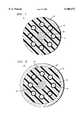
- FIG. 1illustrates a cross-sectional view of an exemplary unit fiber structure incorporating the individual fiber gel layers of the present invention
- FIG. 2illustrates an embodiment of the present invention including an outer foamed polymer layer.
- UFSunit fiber structure
- the following detailed descriptionrelates to an optical fiber cable design and, more particularly to the design of an arrangement referred to in the art as a "unit fiber structure", or UFS.
- the UFSis the central-most portion of an optical fiber cable, particularly a cable deployed for undersea communications.
- the complete cable structureincludes additional outer layers of sheathing and strength members and while not illustrated here, are considered to be part of the final cable structure.
- UFS 10includes a centrally-disposed kingwire 12 which is used as the longitudinal strength member of the UFS.
- Kingwire 12may comprise a steel wire or any other suitable material.
- Surrounding kingwire 12is a plurality of optical fibers 14.
- each optical fiber 14is encased by a gel layer 16.
- the properties and thickness of gel layer 16are chosen to provide adequate support to fiber 14.
- Suitable materials for gel layer 16include thixotropic gels with viscosities up to approximately 400,000 centipoise.
- the gelmay be applied to form a layer having a thickness in the range of, for example, 0.002-0.010" and is applied over optical fiber 14 immediately prior to embedding fiber 14 in support structure described below.
- the plurality of gel-surrounded optical fibersare embedded in a support structure 18 formed of a solid polymeric material, such as a UV-curable acrylate.
- Support structure 18maintains the plurality of fibers 14 in a "tightly coupled" structure, as required for undersea deployment.
- the individual gel layers 16 surrounding each fiberisolate the individual fibers from mechanical forces during manufacturing, installation and recovery activities.
- FIG. 2illustrates an exemplary UFS 20, where UFS 20 includes the same internal components as discussed above in association with FIG. 1.
- a foamed polymeric layer 22is disposed to surround outer surface 24 of UFS 20.
- foamed polymeric layer 22may be formed to comprise a thickness in the range of 0.001"0.0250".
Landscapes
- Physics & Mathematics (AREA)
- Engineering & Computer Science (AREA)
- Manufacturing & Machinery (AREA)
- General Physics & Mathematics (AREA)
- Optics & Photonics (AREA)
- Communication Cables (AREA)
Abstract
Description
Claims (7)
Priority Applications (1)
| Application Number | Priority Date | Filing Date | Title |
|---|---|---|---|
| US09/120,394US6108473A (en) | 1998-07-22 | 1998-07-22 | Optical fiber cable with bend-limiting gel |
Applications Claiming Priority (1)
| Application Number | Priority Date | Filing Date | Title |
|---|---|---|---|
| US09/120,394US6108473A (en) | 1998-07-22 | 1998-07-22 | Optical fiber cable with bend-limiting gel |
Publications (1)
| Publication Number | Publication Date |
|---|---|
| US6108473Atrue US6108473A (en) | 2000-08-22 |
Family
ID=22389986
Family Applications (1)
| Application Number | Title | Priority Date | Filing Date |
|---|---|---|---|
| US09/120,394Expired - LifetimeUS6108473A (en) | 1998-07-22 | 1998-07-22 | Optical fiber cable with bend-limiting gel |
Country Status (1)
| Country | Link |
|---|---|
| US (1) | US6108473A (en) |
Cited By (7)
| Publication number | Priority date | Publication date | Assignee | Title |
|---|---|---|---|---|
| US20030072515A1 (en)* | 2001-10-15 | 2003-04-17 | Ames Gregory H. | Fiber optic curvature sensor for towed hydrophone arrays |
| US6566604B2 (en)* | 1998-03-02 | 2003-05-20 | W. L. Gore & Associates, Inc. | Combination cable and device |
| US7346244B2 (en)* | 2001-03-23 | 2008-03-18 | Draka Comteq B.V. | Coated central strength member for fiber optic cables with reduced shrinkage |
| US20100098387A1 (en)* | 2007-06-28 | 2010-04-22 | Draka Comteq B.V. | Optical Fiber Cable Having Raised Coupling Supports |
| US20100098388A1 (en)* | 2007-06-28 | 2010-04-22 | Draka Comteq B.V. | Optical Fiber Cable Having A Deformable Coupling Element |
| US20100232753A1 (en)* | 2007-06-28 | 2010-09-16 | Draka Comteq B.V. | Coupling Element for Optical Fiber Cables |
| US20120155814A1 (en)* | 2010-12-17 | 2012-06-21 | Optical Cable Corporation | Rugged Fiber Optic Cable |
Citations (2)
| Publication number | Priority date | Publication date | Assignee | Title |
|---|---|---|---|---|
| US4786137A (en)* | 1984-12-31 | 1988-11-22 | Ericsson, Inc. | Optical cable with filling compound and parallel fibers |
| US5384880A (en)* | 1993-12-03 | 1995-01-24 | Alcatel Na Cable Systems, Inc. | Dielectric ribbon optical fiber cable |
- 1998
- 1998-07-22USUS09/120,394patent/US6108473A/ennot_activeExpired - Lifetime
Patent Citations (2)
| Publication number | Priority date | Publication date | Assignee | Title |
|---|---|---|---|---|
| US4786137A (en)* | 1984-12-31 | 1988-11-22 | Ericsson, Inc. | Optical cable with filling compound and parallel fibers |
| US5384880A (en)* | 1993-12-03 | 1995-01-24 | Alcatel Na Cable Systems, Inc. | Dielectric ribbon optical fiber cable |
Cited By (14)
| Publication number | Priority date | Publication date | Assignee | Title |
|---|---|---|---|---|
| US6566604B2 (en)* | 1998-03-02 | 2003-05-20 | W. L. Gore & Associates, Inc. | Combination cable and device |
| US7346244B2 (en)* | 2001-03-23 | 2008-03-18 | Draka Comteq B.V. | Coated central strength member for fiber optic cables with reduced shrinkage |
| US20030072515A1 (en)* | 2001-10-15 | 2003-04-17 | Ames Gregory H. | Fiber optic curvature sensor for towed hydrophone arrays |
| US6728431B2 (en)* | 2001-10-15 | 2004-04-27 | The United States Of America As Represented By The Secretary Of The Navy | Fiber optic curvature sensor for towed hydrophone arrays |
| US20100232753A1 (en)* | 2007-06-28 | 2010-09-16 | Draka Comteq B.V. | Coupling Element for Optical Fiber Cables |
| US20100098388A1 (en)* | 2007-06-28 | 2010-04-22 | Draka Comteq B.V. | Optical Fiber Cable Having A Deformable Coupling Element |
| US20100098387A1 (en)* | 2007-06-28 | 2010-04-22 | Draka Comteq B.V. | Optical Fiber Cable Having Raised Coupling Supports |
| US8036510B2 (en) | 2007-06-28 | 2011-10-11 | Draka Comteq, B.V. | Optical fiber cable having raised coupling supports |
| US8036509B2 (en) | 2007-06-28 | 2011-10-11 | Draka Comteq, B.V. | Optical fiber cable having a deformable coupling element |
| US8103141B2 (en) | 2007-06-28 | 2012-01-24 | Draka Comteq, B.V. | Coupling element for optical fiber cables |
| US8208773B2 (en) | 2007-06-28 | 2012-06-26 | Draka Comteq, B.V. | Optical fiber cable having raised coupling supports |
| US8229263B2 (en) | 2007-06-28 | 2012-07-24 | Draka Comiteq, B.V. | Optical fiber cable having a deformable coupling element |
| US20120155814A1 (en)* | 2010-12-17 | 2012-06-21 | Optical Cable Corporation | Rugged Fiber Optic Cable |
| US8655127B2 (en)* | 2010-12-17 | 2014-02-18 | Optical Cable Corporation | Rugged fiber optic cable |
Similar Documents
| Publication | Publication Date | Title |
|---|---|---|
| CA2092336C (en) | Underwater optical fiber cable having optical fiber coupled to grooved metallic core member | |
| CA2242707C (en) | Combination optical fiber cable | |
| US5050957A (en) | Optical fiber service cable | |
| US5905834A (en) | Combination loose tube optical fiber cable with reverse oscillating lay | |
| US4078853A (en) | Optical communication cable | |
| US4076382A (en) | Optical cable with plastic multilayer sheath | |
| EP1319195B1 (en) | Fiber optic cables with strength members | |
| US5222177A (en) | Underwater optical fiber cable having optical fiber coupled to grooved core member | |
| KR960013801B1 (en) | Fiber optic cable with non-metallic sheathing system | |
| US4331379A (en) | Optical cable with thixotropic filling compound | |
| US4705353A (en) | Optical fiber cable construction | |
| CA2315605A1 (en) | Composite fiber optic/coaxial electrical cables | |
| KR20060030026A (en) | Fiber optic cable with strength member | |
| US4775213A (en) | Composite overhead stranded conductor having a filler between optical fibers and a protective tube | |
| EP1003058A3 (en) | Submarine optical cable, optical fiber unit employed in the submarine optical cable, and method of making optical fiber unit | |
| ZA94739B (en) | Tensile member for communication cables | |
| CN100458485C (en) | Fiber optic assemblies, cable, and manufacturing methods therefor | |
| EP1343041A2 (en) | A compact optical cable | |
| EP1152272A2 (en) | Reinforced buffered fiber optic ribbon cable | |
| US6108473A (en) | Optical fiber cable with bend-limiting gel | |
| US5703984A (en) | Optical fiber cable with plural modular bundles of hermtically sealed optical fibers inside an outer cable sheath | |
| US6704481B2 (en) | Cable assembly having ripcords with excess length and ripcords attached to tape | |
| US6424770B1 (en) | Optical cable | |
| JP4205523B2 (en) | Drop optical fiber cable | |
| JPS6143683B2 (en) |
Legal Events
| Date | Code | Title | Description |
|---|---|---|---|
| AS | Assignment | Owner name:TYCO SUBMARINE SYSTEMS LTD., NEW JERSEY Free format text:ASSIGNMENT OF ASSIGNORS INTEREST;ASSIGNORS:BELAND, WAYNE D.;MURPHY, CRAIG EDWARD;REEL/FRAME:009339/0875 Effective date:19980706 | |
| STCF | Information on status: patent grant | Free format text:PATENTED CASE | |
| FPAY | Fee payment | Year of fee payment:4 | |
| FEPP | Fee payment procedure | Free format text:PAYOR NUMBER ASSIGNED (ORIGINAL EVENT CODE: ASPN); ENTITY STATUS OF PATENT OWNER: LARGE ENTITY | |
| FPAY | Fee payment | Year of fee payment:8 | |
| REMI | Maintenance fee reminder mailed | ||
| FPAY | Fee payment | Year of fee payment:12 | |
| AS | Assignment | Owner name:TYCO ELECTRONICS SUBSEA COMMUNICATIONS LLC, NEW JE Free format text:CHANGE OF NAME;ASSIGNOR:TYCO TELECOMMUNICATIONS (US) INC.;REEL/FRAME:047101/0134 Effective date:20091228 Owner name:TYCOM (US) INC., NEW JERSEY Free format text:CHANGE OF NAME;ASSIGNOR:TYCO SUBMARINE SYSTEMS LTD.;REEL/FRAME:047101/0111 Effective date:20000727 Owner name:TYCO TELECOMMUNICATIONS (US) INC., NEW JERSEY Free format text:CHANGE OF NAME;ASSIGNOR:TYCOM (US) INC.;REEL/FRAME:047141/0671 Effective date:20020102 | |
| AS | Assignment | Owner name:GOLDMAN SACHS LENDING PARTNERS LLC, AS COLLATERAL AGENT, NEW YORK Free format text:SECURITY INTEREST;ASSIGNOR:TYCO ELECTRONICS SUBSEA COMMUNICATIONS LLC;REEL/FRAME:047924/0194 Effective date:20181102 Owner name:GOLDMAN SACHS LENDING PARTNERS LLC, AS COLLATERAL Free format text:SECURITY INTEREST;ASSIGNOR:TYCO ELECTRONICS SUBSEA COMMUNICATIONS LLC;REEL/FRAME:047924/0194 Effective date:20181102 | |
| AS | Assignment | Owner name:SUBCOM, LLC, NEW JERSEY Free format text:CHANGE OF NAME;ASSIGNOR:TYCO ELECTRONICS SUBSEA COMMUNICATIONS LLC;REEL/FRAME:047586/0655 Effective date:20181108 | |
| AS | Assignment | Owner name:TYCO ELECTRONICS SUBSEA COMMUNICATIONS LLC, NEW JERSEY Free format text:RELEASE BY SECURED PARTY;ASSIGNOR:GOLDMAN SACHS LENDING PARTNERS LLC, AS ADMINISTRATIVE AGENT;REEL/FRAME:057215/0950 Effective date:20210427 |