US6108309A - SONET network element simulator - Google Patents
SONET network element simulatorDownload PDFInfo
- Publication number
- US6108309A US6108309AUS08/987,068US98706897AUS6108309AUS 6108309 AUS6108309 AUS 6108309AUS 98706897 AUS98706897 AUS 98706897AUS 6108309 AUS6108309 AUS 6108309A
- Authority
- US
- United States
- Prior art keywords
- network
- network element
- commands
- management system
- alarm
- Prior art date
- Legal status (The legal status is an assumption and is not a legal conclusion. Google has not performed a legal analysis and makes no representation as to the accuracy of the status listed.)
- Expired - Lifetime
Links
- RGNPBRKPHBKNKX-UHFFFAOYSA-NhexaflumuronChemical compoundC1=C(Cl)C(OC(F)(F)C(F)F)=C(Cl)C=C1NC(=O)NC(=O)C1=C(F)C=CC=C1FRGNPBRKPHBKNKX-UHFFFAOYSA-N0.000titleclaimsdescription29
- 230000004044responseEffects0.000claimsabstractdescription43
- 238000004088simulationMethods0.000claimsabstractdescription37
- 238000012545processingMethods0.000claimsabstractdescription21
- 238000012544monitoring processMethods0.000claimsabstractdescription7
- 230000009118appropriate responseEffects0.000claimsabstractdescription6
- 230000006399behaviorEffects0.000claimsabstract11
- 238000004891communicationMethods0.000claimsdescription13
- 238000004519manufacturing processMethods0.000claimsdescription11
- 239000013598vectorSubstances0.000claimsdescription7
- 230000006870functionEffects0.000claimsdescription2
- 230000000977initiatory effectEffects0.000claimsdescription2
- 230000005055memory storageEffects0.000claims2
- 230000003542behavioural effectEffects0.000claims1
- 238000007781pre-processingMethods0.000claims1
- 238000012360testing methodMethods0.000abstractdescription13
- 238000000034methodMethods0.000description137
- 230000008569processEffects0.000description134
- 238000007726management methodMethods0.000description8
- 238000006243chemical reactionMethods0.000description7
- 230000000694effectsEffects0.000description6
- 238000010586diagramMethods0.000description4
- 230000005540biological transmissionEffects0.000description3
- 238000012430stability testingMethods0.000description3
- 238000009662stress testingMethods0.000description3
- 238000012550auditMethods0.000description2
- 230000008901benefitEffects0.000description2
- 230000008859changeEffects0.000description2
- 230000001934delayEffects0.000description2
- 238000002347injectionMethods0.000description2
- 239000007924injectionSubstances0.000description2
- 101000868045Homo sapiens Uncharacterized protein C1orf87Proteins0.000description1
- 102100032994Uncharacterized protein C1orf87Human genes0.000description1
- 238000013459approachMethods0.000description1
- 238000004590computer programMethods0.000description1
- 239000012141concentrateSubstances0.000description1
- 230000001419dependent effectEffects0.000description1
- 238000011161developmentMethods0.000description1
- 239000000835fiberSubstances0.000description1
- 238000001914filtrationMethods0.000description1
- 238000005259measurementMethods0.000description1
- 238000012986modificationMethods0.000description1
- 230000004048modificationEffects0.000description1
- 230000003287optical effectEffects0.000description1
- 230000000737periodic effectEffects0.000description1
- 230000002093peripheral effectEffects0.000description1
- 230000000644propagated effectEffects0.000description1
- 230000000717retained effectEffects0.000description1
- 238000013515scriptMethods0.000description1
- 239000000725suspensionSubstances0.000description1
- 230000001360synchronised effectEffects0.000description1
- 238000012549trainingMethods0.000description1
- 238000013519translationMethods0.000description1
Images


Classifications
- H—ELECTRICITY
- H04—ELECTRIC COMMUNICATION TECHNIQUE
- H04L—TRANSMISSION OF DIGITAL INFORMATION, e.g. TELEGRAPHIC COMMUNICATION
- H04L41/00—Arrangements for maintenance, administration or management of data switching networks, e.g. of packet switching networks
- H04L41/14—Network analysis or design
- H04L41/145—Network analysis or design involving simulating, designing, planning or modelling of a network
- H—ELECTRICITY
- H04—ELECTRIC COMMUNICATION TECHNIQUE
- H04L—TRANSMISSION OF DIGITAL INFORMATION, e.g. TELEGRAPHIC COMMUNICATION
- H04L43/00—Arrangements for monitoring or testing data switching networks
- H04L43/10—Active monitoring, e.g. heartbeat, ping or trace-route
- H—ELECTRICITY
- H04—ELECTRIC COMMUNICATION TECHNIQUE
- H04L—TRANSMISSION OF DIGITAL INFORMATION, e.g. TELEGRAPHIC COMMUNICATION
- H04L43/00—Arrangements for monitoring or testing data switching networks
- H04L43/50—Testing arrangements
Definitions
- the present inventionrelates generally to telecommunications network management systems and specifically, to a SONET network simulator for providing robust testing of a telecommunications network management system.
- Synchronous Optical Networksrepresent a new generation of telecommunications networks and the collection of standards for network architectures and protocols. Coinciding with the rollout of new SONET networks is the development of SONET network management systems.
- a network management system(“NMS”) is used to monitor a telecommunications network, provide status on the state of the network, and provide control over the network to resolve problems such as outages and traffic congestion. Control is provided in the form of commands issued to the network and responses received from the network.
- FIG. 1illustrates a very simplified architecture of a SONET network 50 connected to a Network Management System 75 via a WAN 65 implementing a TCP/IP communications transport protocol.
- a typical SONET networkconsists of thousands of network elements 60 and mediation devices 70 interconnected in many various configurations.
- a non-exhaustive list of network elementsinclude the following types of telecommunications networks, services and equipment: digital and analog transmission systems such as cable, fibre, radio, satellite, etc; restoration systems; re-generation systems and termination equipment; public and private networks including both narrow and broadband ISDNs, mobile networks, etc; transmission terminals such as multiplexers, cross connects, channel translation equipment; operations systems and their peripherals; mainframe computers; front-end processors; file servers; area networks, e.g., WAN, LAN etc.; circuit and packet switched networks; and PBXs.
- Mediation devices 70are used to concentrate several network elements at a single network address and additionally buffer messages sent from network elements 60 to the NMS 75. As shown in FIG. 1, one or more network elements can be connected to a mediation device.
- each of the above-mentioned network elementsautonomously send event messages, such as alarms, to the NMS over the TCP/IP WAN.
- the NMSmay receive 2 alarms/second from 10,000 network elements in steady state operation, and 100 alarms/second in burst modes.
- the network elementsalso receive commands from the NMS including, for example, audit requests, provisioning requests, state requests, and switching commands.
- the network elementsmust then formulate response messages and send them to the NMS.
- These messagesare typically formatted in accordance with an industry standard known as TL-1.
- testingPrior to placing a new or modified NMS in production, the NMS must be thoroughly tested. Testing generally consists of three types: 1) functionality testing to ensure that the NMS meets the functional requirements; 2) stability testing to ensure that the NMS performs uniformly under the same conditions, and in response to the same activity being repeated; and 3) stress testing to ensure that the NMS performs as expected under conditions of high volumes of messages to and from the network.
- the users of the NMSwould require proper training on the operation and use of the new or modified functions of the NMS.
- test toolthat simulates network elements, i.e., receive commands from the NMS and provide responses, as well as send unsolicited messages, such as simulated alarms, to the NMS. While functionality and stability testing may be performed easily with a simple tool that simulates one or a few network elements, stress testing requires simulation of an actual network requiring the generation of very large volumes of messages in order to simulate the thousands of network elements of a dozen or more types that constitute a typical SONET network. In addition, the test tool must support thousands of logical connections to the NMS, to represent the individual connections of each network element it is simulating.
- Network simulators currently availablecannot support the high volumes of message processing from the variety of network element types needed to simulate a large SONET network.
- the present inventionis a SONET network element simulation tool ("SNES") that simulates network elements and mediation devices that collectively form a SONET network, and provides high volumes of unsolicited messages to a SONET network management system (“NMS”), receives commands from an NMS, and sends back appropriate response messages.
- SNESSONET network element simulation tool
- NMSSONET network management system
- the high volumes produced by the network simulation tool of the inventionequal those produced by an actual network, and therefore provides reliable stress and stability testing for the NMS, as well as functionality testing.
- the SONET network element simulator(“SNES”), comprises four logical components: 1) a graphical user interface ("GUI”); 2) an input/output process; 3) a Command/response process; and 4) an autonomous message process.
- GUIgraphical user interface
- These core processesprovide a unique division of labor and data loading scheme that allows the SNES to produce the high volume of message processing required.
- the architectureis also scalable so that it can maintain high volume performance by splitting large scenarios across multiple instances of the core processes thus allowing the invention to take advantage of computer systems that have multiple CPU's.
- the SNESprovides several facets of network simulation and can communicate with an NMS via TCP/IP transport protocol. It provides automatic generation and transmission of unsolicited event messages in high volumes. It receives commands from the NMS or a user input, and formulates appropriate responses to NMS simultaneous to unsolicited message generation. It can read messages that were generated by an actual network and playback those messages to the NMS to repeat an actual production scenario as a test scenario. It also provides the user the ability to perform anomaly testing of the NMS by allowing a user to inject command response delays, message time stamp biasing and simulated mediation device communications failure in real time through the user interface.
- the SNES test toolcould be also used in a lab setting to train users on the proper operation and the use of the NMS by processing captured production data or pre-defined scenarios.
- FIG. 1illustrates a very simplified architecture of a SONET network connected to a Network Management System via a WAN.
- FIG. 2illustrates a systems architecture of the SONET network element simulator ("SNES") of the invention.
- FIGS. 3(a)-3(h)depict exemplary files that are input to the SNES system to define the SONET network elements to be simulated with FIG. 3(a) depicting a portion of an exemplary TL-1 attribute definition file 200; FIG. 3(b) depicting an exemplary of a performance monitoring definition file 210; FIG. 3(c) depicting an exemplary login performance definition file 230; FIG. 3(d) depicting an exemplary provisioning definition file 230; FIG. 3(e) depicting an exemplary alarm definition file 250; FIG. 3(f) depicting an exemplary Mediation Device/NE type definition file 270; FIG. 3(g) depicting an exemplary User Scenario file 285; and FIG. 3(h) depicting an exemplary converted playback data file.
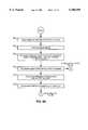
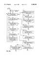
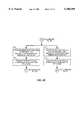
- FIGS. 4(a)-4(e)illustrate the high-level process performed by the SNES of the invention, with FIGS. 4(a) and 4(b) illustrating a functional block diagram of the initialization procedures and I/O process thread of the SNES; FIG. 4(c) illustrating the concurrent initiation and initialization of both the CRP process and AMP process threads; FIG. 4(d) illustrating the high level flow diagram of the CRP process thread; and FIG. 4(e) illustrating the high level flow diagram of the AMP process thread.
- FIG. 5is a flow diagram illustrating the playback conversion for testing log data of an actual SONET network.
- FIG. 2illustrates a systems architecture of the SONET network element simulator 100 ("SNES") of the invention.
- the SNES 100may be realized on a computer system with a single processor or multiple processors and it is equipped with communications ports and cards to enable it to receive data from external sources and to communicate with an NMS 75.
- the SNES 100is connected via multiple TCP/IP links 104 over a WAN to the NMS 75 that is to be tested and it is with these links that the SNES receives commands from and sends messages to the NMS 75 in accordance with the industry standard Transaction Language 1 ("TL-1") protocol as described in Bellcore documents TA-396 and GR-833, the contents of which are incorporated by reference as if fully set forth herein.
- the SNESis built to run on a DEC Alpha 2100 midrange computer running with UNIX operating system. Additional DEC Alpha CPU's may be added to the computer system to provide throughput and scalability.
- the internal architecture of the SNES 100comprises four logical process components and shared memory 140 of the computer it is running on.
- the four component processesare: 1) a Graphical User Interface 110 that reads simulation Configuration/Network Element (Config/NE) data 120 from a set of input files that specifies the equipment type and vendor of each network element and mediation device; 2) an input/output (“I/O") process 125 that handles all communications with the NMS; 3) a Command/Response (“CRP”) process 150 CRP that receives NMS commands from the I/O Process and formulates responses; and 4) an Autonomous Message (“AMP”) process 175 for generating unsolicited messages (events and alarms) for input to the NMS.
- a Graphical User Interface 110that reads simulation Configuration/Network Element (Config/NE) data 120 from a set of input files that specifies the equipment type and vendor of each network element and mediation device
- I/Oinput/output
- CRPCommand/Response
- AMP
- the network elements in the simulatorautonomously send event messages, e.g., alarms, to the NMS over the TCP/IP WAN.
- event messagese.g., alarms
- the NMScan receive 2 alarms/second from 10,000 network elements in steady state operation, and 100 alarms/second in burst modes.
- the network elementsalso receive commands from the NMS including: audit requests, provisioning requests, state requests, and switching commands.
- the network elementsformulate response messages and send them to the NMS formatted in accordance with TL-1. Since several types of network elements and mediation devices may be in use, the TL-1 messages passed between the SONET network and the NMS may actually be in slightly different formats, i.e., each network element/mediation device vendor may have a different interpretation of TL-1.
- the SNESsimulates the exact message structure of each network element and mediation device in use.
- the SNES GUI process 110receives simulation Configuration/Network Element (Config/NE) data 120 from a set of ASCII text files contained in a database 125 that specifies the equipment type and vendor of each network element and mediation device and the configuration of the network elements representing the SONET network, i.e., how the elements are arranged and which network elements are served by which mediation devices.
- Config/NEsimulation Configuration/Network Element
- other types of datacan be input for simulation including: user defined SONET network scenario information; captured production data which is a log of TL-1 messages received by an NMS from an actual SONET network and which can be "played” back; and, user directives including those directives that enable: the suspension/resumption of alarm clearance; the disconnection of mediation device(s); the injection of command response delays; the biasing of message time stamps; the injection of alarms during simulation execution; and, the fast forwarding through a playback scenario.
- the (Config/NE) data 120specifies all of the possible network elements/mediation devices available to a user to specify or configure a SONET network topology, and specifically, which network elements are served by which mediation devices in the network. New types of mediation devices and NE's to be simulated can be easily incorporated by simply transmitting the information to the configuration data contained in the shared memory.
- FIGS. 3(a)-3(g)illustrate the types of ASCII data files 120 that can be input to shared memory.
- FIG. 3(a)depicts an exemplary TL-1 attribute definition file 200 that contains a list of all of the TL-1 attributes, including: the assign identifier ("AID") type section 201 containing the base equipment types of network elements to be simulated and their values in a form recognizable by TL-1; the AID definition section 202 which is used to identify discrete components contained in the base network element equipment; the condition effect attribute 203, the service effect attribute 209, conditions types 204, location attributes 206, monitor types 208 and their respective associated values used and recognized by the system 100 are shown in FIG. 3(a).
- AIDassign identifier
- FIG. 3(b)depicts an exemplary performance monitoring definition file 210 that contains a list of the performance monitoring records that are used by the AMP 175 to generate autonomous performance monitoring messages.
- the performance message capabilityis provisioned to support a realistic model of an NE.
- Each recordincludes one or more of the following fields: the AID definition index field 212, the TL-1 Monitor Value attribute 214; the TL-1 AID Type attribute 216; the TL-1 Location attribute 218; the TL-1 Direction attribute 220; the probability 222 that the record will be reported (a random value between 0 and 1); the TL-1 Time Period attribute 224; and, minimum 226, maximum 227 and default 228 value fields.
- a first simulated performance messagecarries the default value attribute 228.
- the values contained in all subsequent performance messagesare determined by multiplying the maximum value attribute 227 by a randomly generated number between 0 and 1.
- the periodic frequency of the reportis "hardcoded" to be 15 minutes, for example, but the message carries the value by the Monitor Value attribute 214.
- FIG. 3(c)depicts an exemplary logon definition file 230 that defines the login dialogue for a Mediation device and comprises a set of records that define the text string 232 sent to the client and the expected response 233.
- FIG. 3(d)depicts an exemplary Provisioning definition file 240 that defines the provisioning records for each network element.
- Each recordcomprises the following fields: an AID type field 242; a Keyword field 243; minimum 245, maximum 246 and default 247 value fields; a Default state field 248 and a configuration-dependent AID Definition field 249.
- FIG. 3(e)depicts an exemplary alarm definition file 250 containing one or more records that defines all possible alarms that the network element can generate.
- each recordcomprises the following fields: a record indicator field 251; an alarm description field 252 containing the alarm text returned in the alarm message used by the GUI; the AID type field 253 containing the TL-1 AID type attribute; the alarm ID field 254 used by the GUI process; place holder fields 255; a reschedule indicator field 256; the CONDTYPE value (TL-1 message Condition Type attribute) field 257; the AID definition record 258; the configuration dependency indicator 258; the number of alarms associated with the record 259; and, the alarm type field 260.
- TL-1 Notification code/Condition effect attribute 261may include the TL-1 Notification code/Condition effect attribute 261; the SRVEFF value (TL-1 Service Affect attribute) field 262; the DIRN (TL-1 Direction attribute) field 263; the LOCN (TL-1 Location attribute) field 264; and a severity value in field 265.
- FIG. 3(f)depicts an exemplary Mediation Device/NE type definition file 270 that lists all of the network elements modeled by the simulator system 100 with each record defining a unique network element type and containing the following fields: the Network element ID field 271; the TL-1 Attribute definition file name 272; the TL-1 Alarm definition file name 273; the Performance Monitoring Definition file name 274; the Autonomous message format type 275; the command response format type 276; the Login flag 277 which is used to indicate whether a login is required for a client connection; a "Peer” concept flag 278; the provisioning flag 279 to determine if provisioning information is to be modeled for a network element type; a "primary/backup" flag 280; the name of the network element type 281, e.g., Nortel; and two additional fields: a first field indicating the logon definition file 282 if the logon flag is set and, the Provisioning Definition file name 283 if the provisioning flag is set.
- the TL1 messages passed between the SONET network and the NMSmay actually be in slightly different formats, i.e., each network element/mediation device vendor may have a different interpretation of TL-1. Therefore, the SNES simulates the exact message structure of each network element and mediation device in use.
- Files containing SONET network scenario datainclude one or more scripts that instruct the SNES 100 when to autonomously send messages to the NMS.
- scenario dataincludes those SONET network scenarios that have been previously created and saved by the user and that specify the configuration of the SONET network in addition to the start time, frequency, and types of messages to generate during the execution of the scenario.
- FIG. 3(g)depicts an exemplary User Scenario file 285 containing the mediation devices, network elements and alarm definitions saved by the user.
- the first line 288sets forth the header record consisting of the file type, the number of bytes that make up the network element configuration section of the file, the scenario time limit, the number of mediation devices and, a user-specified text description (not shown).
- the remainder of the User Scenario file 285comprises one or more mediation device sections, for example, mediation device sections 290a-290i, and corresponding network element sections, for example, network element sections 292a-292i, and, the event section 295.
- each mediation device sectione.g., section 290i
- each mediation device sectionis a row if fields specifying the following data: the generic name of the mediation device; the primary name of the mediation device; the TCP/IP port number; the device type; the number of regions; the region numbers; the backup flag; the backup name and port if the backup flag is set to equal 1; and, the number of network elements.
- ten (10) network elementsare shown under its control.
- each corresponding network element sectione.g., network element section 292i having ten (10) network elements
- the following data fieldsare specified: the network element name; the status flag; the PM flag; the device type; the region number; the number of modsects; the modsect name(s); and, one or more provisioning records, with four being illustrated in FIG. 3(g).
- the scenario data instructionsare specified in rows containing the following fields that specify: the time of the event 296; the event ID 297; the event duration 298; the event message rate 299; the OPC flag 293; the OPC name 294; the number of network elements; a place holder indicating a non-used field; the network element name 291; two additional place holders indicating non-used fields; and, the number of AID's.
- the SNES 100can also process alarm message input files from captured Production data which is a log of TL-1 messages received by an NMS from actual SONET NE's. Using this as input, the SNES can playback those messages in a test environment to simulate an actual network under actual alarm conditions.
- the Production datais first converted into a SNES readable form using a preprocessor 111 located in the GUI.
- the preprocessor conversion processcomprises the steps of parsing the alarm messages in the log file and creating a "converted" file suitable for input to the core processes.
- the preprocessor 111allows the user to filter the production data based on different criteria. The filtering criteria the user can use are: a time window (start and end time); specific NE types; or NE locations.
- FIG. 5illustrates the process flow of the playback file conversion.
- the userfirst selects to convert a production data file.
- the conversion processfirst determines the time of the earliest alarm in the file at step 704. This time is used as time 0.0 and all other alarm times that are processed are offsets from this time.
- the conversion processreads characters from the file until it gets a pattern match with a TL1 alarm header. Once an alarm header is found, the NE ID is parsed from the alarm header and is looked up in the NE database as indicated at step 712. if the NE is not found, the alarm record is skipped and the process starts looking for a new TL1 alarm header at step 713.
- the NE type and mediation deviceare extracted to be used later in the processing and the alarm offset time is calculated from the alarm time stamp.
- the second line of the alarmis then read and the type of alarm is determined.
- the body of the alarmis then read at step 715 until an end delimiter of the alarm is reached.
- the TL-1 attributesare parsed at step 716 and validated at step 717 against the valid TL-1 values for the NE type and TL-1 attribute. If an invalid value is found, the entire alarm record is skipped and the conversion process starts looking for the next alarm header record.
- the index of the attribute record in the TL-1 attribute definitionsis returned and printed to the converted playback file at step 718.
- This processreturns to step 706 and continues until the end of file is reached as indicated at step 708.
- the conversion processgenerates a list of all mediation devices and NE's.
- the converted playback fileis a formatted list of event records with each record containing detailed information about the original alarm that is used during playback to reproduce the alarm.
- the converted playback file 800contains a file header 802 that identifies the file as a playback file, a NE definition section 803, the format of which is described with respect to FIG.
- a converted playback event section 805containing data records consisting of the following fields: a record indicator field 812, an event time field 814 (including an offset from time 0.0 with time 0.0 being the earliest alarm time), an NE ID field 816, a Mediation Device ID field 818, an Alarm type field 820, a TL1 alarm type field 822, the number of alarm records 824, an Alarm code (ALMCDE) field 826, and, an AID type field 828.
- the remainder of the valuesare one or more data records 810, with each data record containing a set of values that are indices to the TL-1 attribute definition records (FIG. 3(a)). Specifically, there is a value for all the TL-1 attributes that can possibly be part of an alarm record. TL-1 attribute value indices 810 that are used to build the alarm messages.
- indicesinclude the following values: a TL-1 CONDTYPE attribute 830, a TL-1 SEVERITY attribute 832, a TL-1 NTFCNCDE attribute 834, a TL-1 CONDEFF attribute 836, a TL-1 SRVEFF attribute 838, a TL-1 CREF attribute 840, a TL-1 DIRN attribute 842, a TL-1 LOCN attribute 844, a TL-1 MONTYPE attribute 846, a TL-1 i -- MONTM attribute 848, a TL-1 MONVAL attribute 850, a TL-1 TMPER attribute 852, a TL-1 VLDTY attribute 854, a TL-1 THRESHVAL attribute 856, a TL-1 SIDE attribute 858, a TL-1 STATE attribute 860, a TL-1 AID attribute 862, a TL-1 AIDTYPE attribute 864, a TL-1 TBL attribute 866, and, a TL-1 ISLT attribute 868.
- indices to the TL1 attribute definitionsallows the SNES to represent large character strings with a single integer. This not only saves on the disk space required to store the converted playback files, but also minimizes memory usage during run time and allows the AMP to generate the alarms extremely fast by retrieving the character strings required to build the alarm directly from memory when it is time for an alarm to be sent. This same approach is used by the AMP to process user defined scenarios, as will be explained. Negative values for an alarm index mean that the attribute does not exist for a particular alarm record.
- the TL-1 attributes that are supported for playbackare illustrated in FIG. 3(a) as described herein.
- the I/O Process 125handles all communications between the SNES 100 and the NMS 75 via a TCP/IP socket 104 and additionally receives input from the user interface 110 through UNIX Domain sockets 106a,b. Input received from the Config/NE Data files 120 are in the form of a text file read.
- the I/O Process 125After connecting the SNES 100 to the NMS 75, the I/O Process 125 will receive a connection request from the NMS and respond by sending a connection message to the CRP 150 and AMP 175 core processes to establish interprocess communications ("IPC") via UNIX Domain sockets 107a-107c.
- the connection messageinstructs the CRP 150 and AMP 175 processes that communications with a new NMS client connection have been established and the CRP 150 and AMP 175 core processes will respond by initializing the appropriate data structures for the new NMS client connection.
- the I/O process 125then begins to read incoming and outgoing messages and sends them to the appropriate core process recipient(s).
- All solicited messages 130(responses to commands) generated by the CRP process 150 and all unsolicited messages 135 (events and alarms) generated by the AMP process 175 are sent to the NMS via the I/O Process 125.
- All inbound user directives from the GUIare read by the I/O process 125 and are either accepted by the I/O Process 125, or forwarded to either the CRP or AMP processes for execution.
- the user directives that the I/O Process 125 will accept and processare: the Simulation Cancel and Mediation Device Disconnect.
- the CRP process 150receives NMS commands from the I/O Process 125 via connection 108a and formulates responses according to the specific message format of the network element that is being simulated. Specific message formats are contained within the Config/NE data 180 located in shared memory 140. Thus, the CRP receives a command, identifies the network element it is intended for, queries the Config/NE data 180 in shared memory for the appropriate response message structure, formulates a response message, and sends it to the I/O Process 125 which then passes the message on to the NMS. Additionally, the CRP process 150 accepts the inbound user directives from the GUI via the I/O process. As will be explained, the user directives that the CRP process 150 will accept and process are: Client Connection, Client Disconnection, Command Response delay and Message Time Stamp Biasing.
- the AMP process 175generates unsolicited event messages such as alarms for input to the NMS 75. Autonomous messages are generated by reading the user specified scenario file, which specifies what messages are to be sent and when. The "events" specified in the scenario are placed in a time ordered event queue 177 which is processed and updated during the simulation execution. As will be explained, the scenario file itself may be in the form of a "converted" Production Data file for real world message playback. Additionally, the AMP process accepts inbound user directives from the GUI via the I/O process via connection 108b. As will be explained, the user directives that the AMP process 175 will accept and process are: Fast Forward; Pause; Resume; Suspend/Resume Alarm Clearance; Client Connection; Client Disconnection, and Message Time Stamp Biasing.
- each of the core processesshare and update common data through the use of shared memory 140 that is organized in three mains segments: a client connection segment 143 that maintains client connection data including statuses and associated file descriptors; a mediation device segment 146 that contains the device type, the number of network elements under its span of control, and the TCP/IP port information; and, a network element segment 149 that contains detailed information about the state/status of each network element and its low level components and storage of alarms that the network element's generate during the simulation execution. Particularly, in the network element segment 149, the SNES maintains a state vector 147 for each network element and its provisioned components.
- the state vectorsare updated in real time by the I/O 125, CRP 150 and the AMP 175 processes to reflect the actual state of the NE's based on the commands of alarms processed during the scenario.
- This state informationcomprises previous alarms sent and current network element mode resulting from commands previously sent.
- the previous alarms sentare retained in order to provide a realistic response to a "retrieve alarm all" command that can be generated by the network management device, which results in the retransmission of all outstanding alarms previously sent.
- An example command resulting in a network element state changeis a "switch to protect" command which enables a protect channel of a network element to become the active channel. Such a change of "state” would be reflected in that network element's state vector.
- FIG. 2there is a shared memory segment 145 that the three core processes use to communicate with the GUI interface 110 that enables a user to see simulation statistics during run time and to control the simulation execution.
- each instance of the internal SNES architecture shown in FIG. 2may be stacked, i.e., realized multiple times on a single computer system, as indicated by the stack 100'.
- each replicated instanceincludes respective input and outputs to the GUI 110 and NMS 75 to enable simultaneous processing for a plurality of Config/NE process sets, each Config/NE process set defining a limited number of mediation devices, e.g., 150 devices, and associated network elements, depending upon the computer system employed.
- a single instancewill typically utilize about 2.0 Megabytes of shared memory 140 and it should be understood that the amount of shared memory will generally impose the limit on how many instances may be realized on a single computer.
- the stacking of architectures in this mannerprovides scalability as each instance can simulate a process set, in parallel, e.g., when a multi-processing environment, is employed.
- the first instancewill accommodate the simulation of, e.g., 150 mediation devices and the second instance of the stack will simulate the remaining 50 mediation devices/network elements.
- FIGS. 4(a)-4(e)comprise a detailed flowchart illustrating the high-level process performed by the SNES of the invention, with reference to the logical components shown in FIG. 2.
- the userconfigures and initializes the desired scenario through the GUI and the GUI starts the core processes at step 304.
- the I/O processreads the simulation configuration data files and utilizes the information in the data files to allocate and initialize the required shared memory, write the NE configuration data into the shared memory and initialize the TCP/IP sockets that will be used to communicate with the NMS.
- the NE configuration data filesspecifies each of the network elements and mediation devices that are to be simulated and how they are arranged in a network. Additional configuration files used by the SNES describe detailed information about the simulated NE types. The information comprises the TL-1 attribute definitions; the TL-1 alarm messages formats and contents; performance measurement data; login process definition; and provisioning data. This information is read and initialized in local memory by each of the core processes and is not part of the shared memory since it is used as read only information. The CRP and AMP processes both use the same information in the configuration files as will be described herein.
- the I/O processspawns the Command Response and Autonomous Message Processes and sets up a communication path with both the CRP and AMP processes at step 310.
- the Command Response and Autonomous Message process threadswill be described in greater detail with reference to FIGS. 4(c)-4 (e). Particularly, as will be described, each of the three core processes operate continuously and in parallel with steps 502-522 (FIG. 4(b)) describing the continued processing of the I/O Process thread, steps 602-661 (FIGS. 4(c) and 4(d)) describing the continued processing of the CRP process thread and steps 702-763 (FIGS. 4(c) and 4(e)) describing the continued processing of the AMP process thread.
- the I/O process of the inventionis a polling process that continuously polls for both input connections and messages.
- the I/O processfirst continuously polls for new client connections. If a new connection is requested by the NMS, the I/O Process proceeds as follows: first, at step 422, it will accept the connection if a live connection is not already in use for that client and will initialize the client data in shared memory; then, at step 424, it will notify the CRP and AMP processes of the new connection; and, at step 426 will establish a communication path with the CRP and with the AMP to forward outbound command responses and autonomous messages to the NMS client.
- the I/O processcontinues to step 404 where it polls for incoming NMS commands. These commands are in the TL-1 protocol and, when received, are directly forwarded to the CRP as indicated at step 442.
- the Client IDis attached to the message to enable the CRP to know which I/O connection to send the command response back through.
- the processthen continues at step 406, where the I/O process polls for outbound NMS command responses that are generated from commands received by the CRP from the I/O process (as identified in step 442). If outbound NMS command responses are received, the I/O process forwards the contents of the message directly to the NMS client as indicated at step 462.
- step 408the I/O process polls for outbound autonomous messages generated by the AMP in accordance with the user specified scenario.
- the I/O processsimply forwards the contents of the message directly to the NMS client at step 482.
- step 410the I/O process polls for inbound user directives that are sent to the core processes by the GUI. If an incoming user directive is not received, then the process proceeds to step 412, where the I/O process checks the GUI shared memory to see if the simulation is to be terminated. The simulation may be terminated for several reasons: by user request; the simulation duration has been exceeded; or if a core process has failed unexpectedly.
- the I/O processIf the simulation is to be terminated, the I/O process notifies the CRP and AMP to shutdown and close all their open file descriptors. Additionally, the I/O process shuts down and closes all its open file descriptors and removes the shared memory segments. At this point, if the simulation is not to be terminated, the I/O process returns to step 4C2 and will continue the steps described in 402-412.
- the I/O processwill forward the directive to the CRP and AMP processes. After implementing either step 521 or 522, the I/o process will continue the I/O polling thread by returning to step 402.
- the I/O processspawns the CRP and AMP process threads which continuously run in parallel.
- steps 512 and 514 of the CRP process threadare executed in parallel with corresponding steps 513 and 515, respectively, of the AMP process.
- the CRP processreads its configuration files and, in response to the initialization data, the CRP attaches to the shared memory allocated by the I/O process, allocates and initializes its local memory and data structures and, at step 514, establishes communication with the I/O process.
- the AMP process threadperforms the same processing as the CRP as noted in steps 513 and 515.
- the CRP process threadcontinuously polls for inbound messages, NMS Commands and user directives during the simulation execution as indicated at step 602 in FIG. 4(d). If one or more messages have been received, the process parses the TL-1 message header at step 622 and, at step 624 determines whether the message is a NMS Command or a user directive.
- the messageis a user directive
- the directive IDis taken out of the message header which is used to determine if the CRP should process the directive.
- the directives that the CRP processesare: Client Connection, Client Disconnection, Time Stamp Bias, Delay Command Response and Simulation termination. If a Time Stamp Bias is received, as indicated at step 650, the value the user specified in the message body is extracted and added to all subsequent command responses. If a Delay Command Response directive is received, as indicated at step 651a, all subsequent command responses are time stamped and placed in a time ordered queue 157 (FIG. 2).
- the CRPWhen the time has been reached for the message(s) in the queue to be sent, they are taken from the queue and sent to the I/O process as indicated at step 651b in FIG. 4(d).
- a Client Connection directiveis received, as indicated at step 654, the CRP establishes an IPC with the I/O process for the new client.
- a Client Disconnection directiveis received, as indicated at step 653, the CRP closes the open file descriptors for the disconnected client.
- the CRPperforms cleanup procedures by closing all open file descriptors, removing any files created during simulation execution, and detaching itself from the shared memory.
- the initialization of the AMP processcomprises setting up the "event queue" to process the specified alarm messages.
- the event queue 177(FIG. 2) is populated by either a user defined scenario or a converted production set of data.
- the AMP processuses indices to TL-1 attribute definitions (FIG. 3(a)) to represent the character strings that make up the actual alarm.
- the TL-1 alarm definition files(FIG. 3(e)) define the attribute values that make up all the alarms for an NE type.
- each alarm in the scenariois read.
- the alarm IDis taken from each scenario record and is used to lookup the alarm attribute definition values that make up the desired alarm.
- the event record that is added to the event queueis populated with the indices to the TL1 attribute values and are later used in the generation of the alarm.
- the AMPprocesses the event queue, as indicated at step 724, and periodically checks for incoming directives during the simulation execution.
- the AMPpolls for any inbound messages. If one or more messages have been received, it parses the message header and processes the user directive as indicated at step 722. As indicated at step 741, the directive ID is taken out of the message header which is then used to determine if the AMP should process the directive.
- the directives that the AMP processesare: Time Stamp Bias, Simulation Pause/Resume, Suspend/Resume Alarm Clearance, Inject Alarm, Client Connection, Client Disconnection, and Simulation Termination.
- step 750if a Time Stamp Bias is received, the value the user specified in the message body is extracted and added to all subsequent command responses. As indicated at step 751, if a Fast Forward directive is received, the event queue is propagated forward this amount of time. As indicated at step 752, if a Simulation Pause/Resume directive is received, the processing of events in the event queue is paused/resumed. As indicated at step 753, if a Suspend/Resume Alarm clearance directive is received, alarms that are "Clear" alarms are suspended/resumed. As indicated at step 754, if an Inject Alarm directive is received, the alarm data is parsed from the message body and the alarm is added to the event queue.
- the AMPcloses the open file descriptors for the disconnected client.
- the AMPcloses all open file descriptors, removes any files created during simulation execution, and detaches itself from the shared memory.
- the event queue 177(FIG. 2) is processed by the AMP in a time ordered sequence, e.g., FIFO, with the alarm event assigned the earliest time being the first event on the queue.
- the eventis basically an item that describes the elements necessary to build an alarm message which occurs at steps 761 and 762 in FIG. 4(e).
- the messageis formatted based on the information contained in the event and is forwarded to the I/O process.
- the AMPreschedules the event at step 763 if the event has not exceeded its duration and is an event that can be rescheduled. It should be understood that if the processed alarm effects the state of a network element(s), the state vector indicating the status of the affected network elements is updated.
- communications devicese.g., switches
- bandwidth throughput and error rate performance criteriabeing used to simulate the generation of alarms and performance messages.
Landscapes
- Engineering & Computer Science (AREA)
- Computer Networks & Wireless Communication (AREA)
- Signal Processing (AREA)
- Data Exchanges In Wide-Area Networks (AREA)
Abstract
Description
Claims (20)
Priority Applications (1)
| Application Number | Priority Date | Filing Date | Title |
|---|---|---|---|
| US08/987,068US6108309A (en) | 1997-12-08 | 1997-12-08 | SONET network element simulator |
Applications Claiming Priority (1)
| Application Number | Priority Date | Filing Date | Title |
|---|---|---|---|
| US08/987,068US6108309A (en) | 1997-12-08 | 1997-12-08 | SONET network element simulator |
Publications (1)
| Publication Number | Publication Date |
|---|---|
| US6108309Atrue US6108309A (en) | 2000-08-22 |
Family
ID=25533033
Family Applications (1)
| Application Number | Title | Priority Date | Filing Date |
|---|---|---|---|
| US08/987,068Expired - LifetimeUS6108309A (en) | 1997-12-08 | 1997-12-08 | SONET network element simulator |
Country Status (1)
| Country | Link |
|---|---|
| US (1) | US6108309A (en) |
Cited By (90)
| Publication number | Priority date | Publication date | Assignee | Title |
|---|---|---|---|---|
| US6294991B1 (en) | 1998-09-08 | 2001-09-25 | Mci Communications Corporation | Method and system therefor for ensuring a true activation of distributed restoration in a telecommunications network |
| US6337846B1 (en) | 1998-09-08 | 2002-01-08 | Mci Worldcom, Inc. | Quantification of the quality of spare links in a telecommunications network |
| US20020032762A1 (en)* | 2000-02-17 | 2002-03-14 | Price Charles A. | System and method for remotely configuring testing laboratories |
| US6404733B1 (en)* | 1998-09-08 | 2002-06-11 | Mci Worldcom, Inc. | Method of exercising a distributed restoration process in an operational telecommunications network |
| US20020077787A1 (en)* | 2000-12-18 | 2002-06-20 | Theodore Rappaport | Textual and graphical demarcation of location, and interpretation of measurements |
| US6411598B1 (en) | 1997-03-12 | 2002-06-25 | Mci Communications Corporation | Signal conversion for fault isolation |
| US6414940B1 (en) | 1997-03-12 | 2002-07-02 | Mci Communications Corporation | Method and system of managing unidirectional failures in a distributed restoration network |
| US6418117B1 (en) | 1998-09-08 | 2002-07-09 | Mci Worldcom, Inc. | Out of band messaging in a DRA network |
| US20020101824A1 (en)* | 2000-03-28 | 2002-08-01 | Ziedman Robert M. | System and method for connecting a logic circuit simulation to a network |
| WO2002057965A3 (en)* | 2000-12-04 | 2002-09-12 | Rensselaer Polytech Inst | Fast network simulation using network decomposition |
| US6496476B1 (en) | 1997-03-12 | 2002-12-17 | Worldcom, Inc. | System and method for restricted reuse of intact portions of failed paths |
| US20030014233A1 (en)* | 1999-07-14 | 2003-01-16 | Rappaport Theodore S. | System for the three-dimensional display of wireless communication system performance |
| US20030023412A1 (en)* | 2001-02-14 | 2003-01-30 | Rappaport Theodore S. | Method and system for modeling and managing terrain, buildings, and infrastructure |
| US6532237B1 (en)* | 1999-02-16 | 2003-03-11 | 3Com Corporation | Apparatus for and method of testing a hierarchical PNNI based ATM network |
| US20030050878A1 (en)* | 1999-05-26 | 2003-03-13 | Rappaport Theodore S. | Method and system for generating a real time bill of materials and evaluating network performance |
| US20030055932A1 (en)* | 2001-09-19 | 2003-03-20 | Dell Products L.P. | System and method for configuring a storage area network |
| US20030140128A1 (en)* | 2002-01-18 | 2003-07-24 | Dell Products L.P. | System and method for validating a network |
| US6625590B1 (en)* | 1999-08-10 | 2003-09-23 | International Business Machines Corporation | Command line interface for reducing user input in a network management device |
| US20030218984A1 (en)* | 2002-05-22 | 2003-11-27 | Nec Corporation | Communication system multiplexer included in the system, line performance test method and recording medium having program recorded thereon |
| US20030225556A1 (en)* | 2000-12-28 | 2003-12-04 | Zeidman Robert Marc | Apparatus and method for connecting hardware to a circuit simulation |
| US20030225564A1 (en)* | 2000-12-28 | 2003-12-04 | Zeidman Robert Marc | Apparatus and method for connecting a hardware emulator to a computer peripheral |
| US6687748B1 (en)* | 2000-01-04 | 2004-02-03 | Cisco Technology, Inc. | Network management system and method of operation |
| US20040027384A1 (en)* | 2002-08-12 | 2004-02-12 | Gilbert Levesque | End-to-end tracing of wavelength parameters in a wavelength division multiplexing span of a fiber optic network |
| US20040054769A1 (en)* | 2002-07-31 | 2004-03-18 | Alcatel | System for managing networks using rules and including an inference engine |
| KR100425500B1 (en)* | 2001-09-20 | 2004-03-30 | 엘지전자 주식회사 | simulator of the EMS and controlling method therefore |
| US20040064300A1 (en)* | 2002-09-26 | 2004-04-01 | Mathiske Bernd J.W. | Method and apparatus for starting simulation of a computer system from a process checkpoint within a simulator |
| US20040066400A1 (en)* | 2002-10-08 | 2004-04-08 | Overture Networks, Inc. | Command line interface with indication of network element status |
| US6721769B1 (en) | 1999-05-26 | 2004-04-13 | Wireless Valley Communications, Inc. | Method and system for a building database manipulator |
| US20040088148A1 (en)* | 2001-12-03 | 2004-05-06 | Szymanski Boleslaw K. | Fast network simulation using network decomposition |
| US20040133415A1 (en)* | 2000-08-04 | 2004-07-08 | Theodore Rappaport | Method and system, with component kits, for designing or deploying a communications network which considers frequency dependent effects |
| US20040143428A1 (en)* | 2003-01-22 | 2004-07-22 | Rappaport Theodore S. | System and method for automated placement or configuration of equipment for obtaining desired network performance objectives |
| US6813240B1 (en) | 1999-06-11 | 2004-11-02 | Mci, Inc. | Method of identifying low quality links in a telecommunications network |
| US20040229623A1 (en)* | 1999-05-26 | 2004-11-18 | Rappaport Theodore S. | Method and system for analysis, design, and optimization of communication networks |
| US6822941B1 (en)* | 1998-02-18 | 2004-11-23 | Siemens Aktiengesellschaft | Method and network element for relaying event messages |
| US20040259555A1 (en)* | 2003-04-23 | 2004-12-23 | Rappaport Theodore S. | System and method for predicting network performance and position location using multiple table lookups |
| US20040259554A1 (en)* | 2003-04-23 | 2004-12-23 | Rappaport Theodore S. | System and method for ray tracing using reception surfaces |
| US20050036484A1 (en)* | 2001-03-09 | 2005-02-17 | Barker Andrew James | Telecommunications networks |
| US20050043933A1 (en)* | 2000-08-04 | 2005-02-24 | Theodore Rappaport | System and method for efficiently visualizing and comparing communication network system performance |
| US6876951B2 (en) | 1998-12-29 | 2005-04-05 | Wireless Valley Communications, Inc. | Method for creating a computer model and measurement database of a wireless communication network |
| US6892172B1 (en)* | 2000-02-16 | 2005-05-10 | Raj Kumar Singh | Customizable simulation model of an ATM/SONET framer for system level verification and performance characterization |
| US20050135809A1 (en)* | 2003-12-23 | 2005-06-23 | Paddy Vishnubhatt | Service and resource management framework for optical networks |
| US6925642B1 (en)* | 1999-04-29 | 2005-08-02 | Hewlett-Packard Development Company, L.P. | Distributed computer network which spawns inter-node parallel processes based on resource availability |
| US6971063B1 (en) | 2000-07-28 | 2005-11-29 | Wireless Valley Communications Inc. | System, method, and apparatus for portable design, deployment, test, and optimization of a communication network |
| US20050265321A1 (en)* | 2000-09-25 | 2005-12-01 | Theodore Rappaport | System and method for design, tracking, measurement, prediction and optimization of data communication networks |
| US20060004559A1 (en)* | 2004-06-30 | 2006-01-05 | Gladfelter David K | Simulation of application-instrument communications |
| US6996510B1 (en)* | 2000-01-21 | 2006-02-07 | Metasolv Software, Inc. | System and method for modeling communication networks |
| US20060041415A1 (en)* | 2004-08-20 | 2006-02-23 | Dybas Richard S | Apparatus, system, and method for inter-device communications simulation |
| US20060038084A1 (en)* | 2004-07-30 | 2006-02-23 | The Boeing Company | Methods and systems for advanced spaceport information management |
| US7055107B1 (en) | 2000-09-22 | 2006-05-30 | Wireless Valley Communications, Inc. | Method and system for automated selection of optimal communication network equipment model, position, and configuration |
| US20060116853A1 (en)* | 2001-12-17 | 2006-06-01 | Theodore Rappaport | Textual and graphical demarcation of location, and interpretation of measurments |
| US7085697B1 (en) | 2000-08-04 | 2006-08-01 | Motorola, Inc. | Method and system for designing or deploying a communications network which considers component attributes |
| US7096173B1 (en) | 2000-08-04 | 2006-08-22 | Motorola, Inc. | Method and system for designing or deploying a communications network which allows simultaneous selection of multiple components |
| US20060221860A1 (en)* | 2005-03-31 | 2006-10-05 | Microsoft Corporation | Nodal pattern configuration |
| US20070010982A1 (en)* | 2005-06-23 | 2007-01-11 | Cpu Technology, Inc. | Automatic time warp for electronic system simulation |
| US7171208B2 (en) | 2000-08-04 | 2007-01-30 | Motorola, Inc. | Method and system, with component kits for designing or deploying a communications network which considers frequency dependent effects |
| US7174285B1 (en)* | 2000-03-27 | 2007-02-06 | Lucent Technologies Inc. | Method and apparatus for assessing quality of service for communication networks |
| US7185075B1 (en)* | 1999-05-26 | 2007-02-27 | Fujitsu Limited | Element management system with dynamic database updates based on parsed snooping |
| US20070112549A1 (en)* | 2005-10-31 | 2007-05-17 | International Business Machines Corporation | Method and apparatus for a database workload simulator |
| CN1324844C (en)* | 2004-06-02 | 2007-07-04 | 中兴通讯股份有限公司 | Method for providing data to members of network synchronously by gating system |
| US7243054B2 (en) | 1999-07-14 | 2007-07-10 | Wireless Valley Communications, Inc. | Method and system for displaying network performance, cost, maintenance, and infrastructure wiring diagram |
| US7254524B1 (en)* | 2001-07-12 | 2007-08-07 | Cisco Technology, Inc. | Method and system for a simulation authoring environment implemented in creating a simulation application |
| CN100344106C (en)* | 2004-05-26 | 2007-10-17 | 华为技术有限公司 | Method and system for implementing white box virtual network element in optical transmission network management system |
| US7295119B2 (en) | 2003-01-22 | 2007-11-13 | Wireless Valley Communications, Inc. | System and method for indicating the presence or physical location of persons or devices in a site specific representation of a physical environment |
| US20080163243A1 (en)* | 2003-04-30 | 2008-07-03 | Kalmuk David C | Method and system for optimizing file table usage |
| CN100479394C (en)* | 2007-01-15 | 2009-04-15 | 华为技术有限公司 | Simulated testing system and method of the business processing network element |
| US20090268605A1 (en)* | 2008-04-23 | 2009-10-29 | Verizon Business Network Services, Inc. | Method and System for Network Backbone Analysis |
| US20100100823A1 (en)* | 2008-10-21 | 2010-04-22 | Synactive, Inc. | Method and apparatus for generating a web-based user interface |
| USRE42227E1 (en) | 2000-03-28 | 2011-03-15 | Ionipas Transfer Company, Llc | Apparatus and method for connecting hardware to a circuit simulation |
| US7958267B1 (en) | 2002-11-19 | 2011-06-07 | Quadrus Corporation | Message traffic interception system |
| US7962588B1 (en)* | 2002-02-01 | 2011-06-14 | Ciena Corporation | Method and system for managing optical network elements |
| US20120117109A1 (en)* | 2009-06-02 | 2012-05-10 | Nokia Siemens Networks Oy | Network element integration |
| US8213340B1 (en)* | 2005-08-15 | 2012-07-03 | Tellabs Operations, Inc. | System and method for managing a node split across multiple network elements |
| US20120191838A1 (en)* | 2008-11-20 | 2012-07-26 | Synactive, Inc. | System and Method for Improved SAP Communications |
| US20130103376A1 (en)* | 2011-10-25 | 2013-04-25 | Cellco Partnership D/B/A Verizon Wireless | Multiple client simulator for push engine |
| US8775152B2 (en) | 2010-07-30 | 2014-07-08 | Ciena Corporation | Multi-core, multi-blade, and multi-node network environment simulation |
| US8918682B2 (en) | 2012-11-14 | 2014-12-23 | Altera Corporation | Methods for testing network circuitry |
| US8990427B2 (en) | 2010-04-13 | 2015-03-24 | Synactive, Inc. | Method and apparatus for accessing an enterprise resource planning system via a mobile device |
| US9069627B2 (en) | 2012-06-06 | 2015-06-30 | Synactive, Inc. | Method and apparatus for providing a dynamic execution environment in network communication between a client and a server |
| WO2015117469A1 (en)* | 2014-08-19 | 2015-08-13 | 中兴通讯股份有限公司 | Method, apparatus and system for learning device capability |
| US20150286416A1 (en)* | 2014-04-07 | 2015-10-08 | International Business Machines Corporation | Introducing Latency And Delay For Test Or Debug Purposes In A SAN Environment |
| US20150288570A1 (en)* | 2014-04-07 | 2015-10-08 | International Business Machines Corporation | Introducing Latency And Delay In A SAN Environment |
| US9300745B2 (en) | 2012-07-27 | 2016-03-29 | Synactive, Inc. | Dynamic execution environment in network communications |
| CN105991322A (en)* | 2015-02-09 | 2016-10-05 | 中兴通讯股份有限公司 | Processing method and device for collection adapter management system |
| CN108712285A (en)* | 2018-05-18 | 2018-10-26 | 国家电网公司信息通信分公司 | A kind of analog simulation method and device of optical transport network |
| US10116548B2 (en) | 2016-08-26 | 2018-10-30 | Red Hat, Inc. | Protocol-based packet traffic creation |
| CN108737134A (en)* | 2017-04-19 | 2018-11-02 | 中兴通讯股份有限公司 | A kind of analogue web element testing method and device |
| US10523767B2 (en) | 2008-11-20 | 2019-12-31 | Synactive, Inc. | System and method for improved SAP communications |
| US10812317B1 (en)* | 2015-03-06 | 2020-10-20 | Sprint Communcations Company L.P. | Telecommunication network trouble ticket system |
| US11232052B2 (en)* | 2019-07-22 | 2022-01-25 | Estinet Technologies Incorporation | Timing control method and system applied on the network simulator platform |
| US20250220036A1 (en)* | 2023-12-29 | 2025-07-03 | Acronis International Gmbh | Systems and methods for testing distributed systems using injected network partitions |
Citations (7)
| Publication number | Priority date | Publication date | Assignee | Title |
|---|---|---|---|---|
| US4725970A (en)* | 1985-02-05 | 1988-02-16 | Sanders Associates, Inc. | Simulation device |
| US5473596A (en)* | 1993-12-09 | 1995-12-05 | At&T Corp. | Method and system for monitoring telecommunication network element alarms |
| US5726979A (en)* | 1996-02-22 | 1998-03-10 | Mci Corporation | Network management system |
| US5761486A (en)* | 1995-08-21 | 1998-06-02 | Fujitsu Limited | Method and apparatus for simulating a computer network system through collected data from the network |
| US5809282A (en)* | 1995-06-07 | 1998-09-15 | Grc International, Inc. | Automated network simulation and optimization system |
| US5881237A (en)* | 1996-09-10 | 1999-03-09 | Ganymede Software, Inc. | Methods, systems and computer program products for test scenario based communications network performance testing |
| US5907696A (en)* | 1996-07-03 | 1999-05-25 | Cabletron Systems, Inc. | Network device simulator |
- 1997
- 1997-12-08USUS08/987,068patent/US6108309A/ennot_activeExpired - Lifetime
Patent Citations (7)
| Publication number | Priority date | Publication date | Assignee | Title |
|---|---|---|---|---|
| US4725970A (en)* | 1985-02-05 | 1988-02-16 | Sanders Associates, Inc. | Simulation device |
| US5473596A (en)* | 1993-12-09 | 1995-12-05 | At&T Corp. | Method and system for monitoring telecommunication network element alarms |
| US5809282A (en)* | 1995-06-07 | 1998-09-15 | Grc International, Inc. | Automated network simulation and optimization system |
| US5761486A (en)* | 1995-08-21 | 1998-06-02 | Fujitsu Limited | Method and apparatus for simulating a computer network system through collected data from the network |
| US5726979A (en)* | 1996-02-22 | 1998-03-10 | Mci Corporation | Network management system |
| US5907696A (en)* | 1996-07-03 | 1999-05-25 | Cabletron Systems, Inc. | Network device simulator |
| US5881237A (en)* | 1996-09-10 | 1999-03-09 | Ganymede Software, Inc. | Methods, systems and computer program products for test scenario based communications network performance testing |
Cited By (165)
| Publication number | Priority date | Publication date | Assignee | Title |
|---|---|---|---|---|
| US6507561B1 (en) | 1997-03-12 | 2003-01-14 | Worldcom, Inc. | Telecommunications network distributed restoration method and system |
| US6411598B1 (en) | 1997-03-12 | 2002-06-25 | Mci Communications Corporation | Signal conversion for fault isolation |
| US6414940B1 (en) | 1997-03-12 | 2002-07-02 | Mci Communications Corporation | Method and system of managing unidirectional failures in a distributed restoration network |
| US6496476B1 (en) | 1997-03-12 | 2002-12-17 | Worldcom, Inc. | System and method for restricted reuse of intact portions of failed paths |
| US6822941B1 (en)* | 1998-02-18 | 2004-11-23 | Siemens Aktiengesellschaft | Method and network element for relaying event messages |
| US6337846B1 (en) | 1998-09-08 | 2002-01-08 | Mci Worldcom, Inc. | Quantification of the quality of spare links in a telecommunications network |
| US6294991B1 (en) | 1998-09-08 | 2001-09-25 | Mci Communications Corporation | Method and system therefor for ensuring a true activation of distributed restoration in a telecommunications network |
| US6404733B1 (en)* | 1998-09-08 | 2002-06-11 | Mci Worldcom, Inc. | Method of exercising a distributed restoration process in an operational telecommunications network |
| US6418117B1 (en) | 1998-09-08 | 2002-07-09 | Mci Worldcom, Inc. | Out of band messaging in a DRA network |
| US7096160B2 (en) | 1998-12-29 | 2006-08-22 | Wireless Valley Communications, Inc. | System and method for measuring and monitoring wireless network performance in campus and indoor environments |
| US6876951B2 (en) | 1998-12-29 | 2005-04-05 | Wireless Valley Communications, Inc. | Method for creating a computer model and measurement database of a wireless communication network |
| US6532237B1 (en)* | 1999-02-16 | 2003-03-11 | 3Com Corporation | Apparatus for and method of testing a hierarchical PNNI based ATM network |
| US6925642B1 (en)* | 1999-04-29 | 2005-08-02 | Hewlett-Packard Development Company, L.P. | Distributed computer network which spawns inter-node parallel processes based on resource availability |
| US7155228B2 (en) | 1999-05-26 | 2006-12-26 | Wireless Valley Communications, Inc. | Method and system for analysis, design, and optimization of communication networks |
| US20040186847A1 (en)* | 1999-05-26 | 2004-09-23 | Rappaport Theodore S. | Method and apparatus for a transportable environmental database for communications network management and engineering |
| US20030050878A1 (en)* | 1999-05-26 | 2003-03-13 | Rappaport Theodore S. | Method and system for generating a real time bill of materials and evaluating network performance |
| US20040177085A1 (en)* | 1999-05-26 | 2004-09-09 | Theodore Rappaport | Method and system for using raster images to create a transportable building database for communications network engineering and management |
| US20040162840A1 (en)* | 1999-05-26 | 2004-08-19 | Theodore Rappaport | System and method for a three dimensional database modeler for wireless communications network management and engineering |
| US20040229623A1 (en)* | 1999-05-26 | 2004-11-18 | Rappaport Theodore S. | Method and system for analysis, design, and optimization of communication networks |
| US7596518B2 (en) | 1999-05-26 | 2009-09-29 | Wireless Valley Communications, Inc. | Method and system for generating a real time bill of materials and evaluating network performance |
| US6721769B1 (en) | 1999-05-26 | 2004-04-13 | Wireless Valley Communications, Inc. | Method and system for a building database manipulator |
| US20050131619A1 (en)* | 1999-05-26 | 2005-06-16 | Rappaport Theodore S. | Method and system for a building database manipulator |
| US7711687B2 (en) | 1999-05-26 | 2010-05-04 | Wireless Valley Communications, Inc. | Method and system for using raster images to create a transportable building database for communications network engineering and management |
| US7185075B1 (en)* | 1999-05-26 | 2007-02-27 | Fujitsu Limited | Element management system with dynamic database updates based on parsed snooping |
| US6850946B1 (en) | 1999-05-26 | 2005-02-01 | Wireless Valley Communications, Inc. | Method and system for a building database manipulator |
| US6813240B1 (en) | 1999-06-11 | 2004-11-02 | Mci, Inc. | Method of identifying low quality links in a telecommunications network |
| US20030014233A1 (en)* | 1999-07-14 | 2003-01-16 | Rappaport Theodore S. | System for the three-dimensional display of wireless communication system performance |
| US7243054B2 (en) | 1999-07-14 | 2007-07-10 | Wireless Valley Communications, Inc. | Method and system for displaying network performance, cost, maintenance, and infrastructure wiring diagram |
| US7299168B2 (en) | 1999-07-14 | 2007-11-20 | Wireless Valley Communications, Inc. | System for the three-dimensional display of wireless communication system performance |
| US6625590B1 (en)* | 1999-08-10 | 2003-09-23 | International Business Machines Corporation | Command line interface for reducing user input in a network management device |
| US6687748B1 (en)* | 2000-01-04 | 2004-02-03 | Cisco Technology, Inc. | Network management system and method of operation |
| US6996510B1 (en)* | 2000-01-21 | 2006-02-07 | Metasolv Software, Inc. | System and method for modeling communication networks |
| US6892172B1 (en)* | 2000-02-16 | 2005-05-10 | Raj Kumar Singh | Customizable simulation model of an ATM/SONET framer for system level verification and performance characterization |
| US7133906B2 (en)* | 2000-02-17 | 2006-11-07 | Lumenare Networks | System and method for remotely configuring testing laboratories |
| US20020032762A1 (en)* | 2000-02-17 | 2002-03-14 | Price Charles A. | System and method for remotely configuring testing laboratories |
| US7174285B1 (en)* | 2000-03-27 | 2007-02-06 | Lucent Technologies Inc. | Method and apparatus for assessing quality of service for communication networks |
| US8380481B2 (en) | 2000-03-28 | 2013-02-19 | Ionipas Transfer Company, Llc | Conveying data from a hardware device to a circuit simulation |
| US20110125479A1 (en)* | 2000-03-28 | 2011-05-26 | Robert Marc Zeidman | Use of hardware peripheral devices with software simulations |
| US20020101824A1 (en)* | 2000-03-28 | 2002-08-01 | Ziedman Robert M. | System and method for connecting a logic circuit simulation to a network |
| US20070061127A1 (en)* | 2000-03-28 | 2007-03-15 | Zeidman Robert M | Apparatus and method for connecting hardware to a circuit simulation |
| US7835897B2 (en) | 2000-03-28 | 2010-11-16 | Robert Marc Zeidman | Apparatus and method for connecting hardware to a circuit simulation |
| US20070064694A1 (en)* | 2000-03-28 | 2007-03-22 | Ziedman Robert M | System and method for connecting a logic circuit simulation to a network |
| US8195442B2 (en) | 2000-03-28 | 2012-06-05 | Ionipas Transfer Company, Llc | Use of hardware peripheral devices with software simulations |
| USRE42227E1 (en) | 2000-03-28 | 2011-03-15 | Ionipas Transfer Company, Llc | Apparatus and method for connecting hardware to a circuit simulation |
| US8160863B2 (en)* | 2000-03-28 | 2012-04-17 | Ionipas Transfer Company, Llc | System and method for connecting a logic circuit simulation to a network |
| US20060015814A1 (en)* | 2000-07-28 | 2006-01-19 | Rappaport Theodore S | System, method, and apparatus for portable design, deployment, test, and optimization of a communication network |
| US6971063B1 (en) | 2000-07-28 | 2005-11-29 | Wireless Valley Communications Inc. | System, method, and apparatus for portable design, deployment, test, and optimization of a communication network |
| US7933605B2 (en) | 2000-08-04 | 2011-04-26 | Motorola Solutions, Inc. | Method and system, with component kits for designing or deploying a communications network which considers frequency dependent effects |
| US20050043933A1 (en)* | 2000-08-04 | 2005-02-24 | Theodore Rappaport | System and method for efficiently visualizing and comparing communication network system performance |
| US20040133415A1 (en)* | 2000-08-04 | 2004-07-08 | Theodore Rappaport | Method and system, with component kits, for designing or deploying a communications network which considers frequency dependent effects |
| US7096173B1 (en) | 2000-08-04 | 2006-08-22 | Motorola, Inc. | Method and system for designing or deploying a communications network which allows simultaneous selection of multiple components |
| US7246045B1 (en) | 2000-08-04 | 2007-07-17 | Wireless Valley Communication, Inc. | System and method for efficiently visualizing and comparing communication network system performance |
| US8290499B2 (en) | 2000-08-04 | 2012-10-16 | Wireless Valley Communications Inc. | Method and system to model frequency dependent effects of a communciations network |
| US7680644B2 (en) | 2000-08-04 | 2010-03-16 | Wireless Valley Communications, Inc. | Method and system, with component kits, for designing or deploying a communications network which considers frequency dependent effects |
| US7085697B1 (en) | 2000-08-04 | 2006-08-01 | Motorola, Inc. | Method and system for designing or deploying a communications network which considers component attributes |
| US7286971B2 (en) | 2000-08-04 | 2007-10-23 | Wireless Valley Communications, Inc. | System and method for efficiently visualizing and comparing communication network system performance |
| US7171208B2 (en) | 2000-08-04 | 2007-01-30 | Motorola, Inc. | Method and system, with component kits for designing or deploying a communications network which considers frequency dependent effects |
| US7055107B1 (en) | 2000-09-22 | 2006-05-30 | Wireless Valley Communications, Inc. | Method and system for automated selection of optimal communication network equipment model, position, and configuration |
| US20050265321A1 (en)* | 2000-09-25 | 2005-12-01 | Theodore Rappaport | System and method for design, tracking, measurement, prediction and optimization of data communication networks |
| US8503336B2 (en) | 2000-09-25 | 2013-08-06 | Wireless Valley Communications, Inc | System and method for design, tracking, measurement, prediction and optimization of data communication networks |
| US6973622B1 (en) | 2000-09-25 | 2005-12-06 | Wireless Valley Communications, Inc. | System and method for design, tracking, measurement, prediction and optimization of data communication networks |
| WO2002057965A3 (en)* | 2000-12-04 | 2002-09-12 | Rensselaer Polytech Inst | Fast network simulation using network decomposition |
| US7019753B2 (en) | 2000-12-18 | 2006-03-28 | Wireless Valley Communications, Inc. | Textual and graphical demarcation of location from an environmental database, and interpretation of measurements including descriptive metrics and qualitative values |
| US20020077787A1 (en)* | 2000-12-18 | 2002-06-20 | Theodore Rappaport | Textual and graphical demarcation of location, and interpretation of measurements |
| US7266490B2 (en)* | 2000-12-28 | 2007-09-04 | Robert Marc Zeidman | Apparatus and method for connecting hardware to a circuit simulation |
| US20070016396A9 (en)* | 2000-12-28 | 2007-01-18 | Zeidman Robert M | Apparatus and method for connecting a hardware emulator to a computer peripheral |
| US20030225564A1 (en)* | 2000-12-28 | 2003-12-04 | Zeidman Robert Marc | Apparatus and method for connecting a hardware emulator to a computer peripheral |
| US20030225556A1 (en)* | 2000-12-28 | 2003-12-04 | Zeidman Robert Marc | Apparatus and method for connecting hardware to a circuit simulation |
| US20070061122A9 (en)* | 2000-12-28 | 2007-03-15 | Zeidman Robert M | Apparatus and method for connecting hardware to a circuit simulation |
| US20030023412A1 (en)* | 2001-02-14 | 2003-01-30 | Rappaport Theodore S. | Method and system for modeling and managing terrain, buildings, and infrastructure |
| US7164883B2 (en) | 2001-02-14 | 2007-01-16 | Motorola. Inc. | Method and system for modeling and managing terrain, buildings, and infrastructure |
| EP1368759A4 (en)* | 2001-02-14 | 2006-02-22 | Wireless Valley Comm Inc | Method and system for modeling and managing terrain, buildings, and infrastructure |
| US20050036484A1 (en)* | 2001-03-09 | 2005-02-17 | Barker Andrew James | Telecommunications networks |
| US9473242B2 (en) | 2001-03-09 | 2016-10-18 | Ericsson Ab | Establishing connection across a connection-oriented first telecommunications network in response to a connection request from a second telecommunications network |
| US7830869B2 (en)* | 2001-03-09 | 2010-11-09 | Ericsson Ab | Establishing connection across a connection-oriented first telecommunications network in response to a connection request from a second telecommunications network |
| US7254524B1 (en)* | 2001-07-12 | 2007-08-07 | Cisco Technology, Inc. | Method and system for a simulation authoring environment implemented in creating a simulation application |
| US20030055932A1 (en)* | 2001-09-19 | 2003-03-20 | Dell Products L.P. | System and method for configuring a storage area network |
| US20080065748A1 (en)* | 2001-09-19 | 2008-03-13 | Dell Products L.P. | System and Method for Configuring a Storage Area Network |
| US7603446B2 (en) | 2001-09-19 | 2009-10-13 | Dell Products L.P. | System and method for configuring a storage area network |
| KR100425500B1 (en)* | 2001-09-20 | 2004-03-30 | 엘지전자 주식회사 | simulator of the EMS and controlling method therefore |
| US20040088148A1 (en)* | 2001-12-03 | 2004-05-06 | Szymanski Boleslaw K. | Fast network simulation using network decomposition |
| US7574323B2 (en) | 2001-12-17 | 2009-08-11 | Wireless Valley Communications, Inc. | Textual and graphical demarcation of location, and interpretation of measurements |
| US20060116853A1 (en)* | 2001-12-17 | 2006-06-01 | Theodore Rappaport | Textual and graphical demarcation of location, and interpretation of measurments |
| US20030140128A1 (en)* | 2002-01-18 | 2003-07-24 | Dell Products L.P. | System and method for validating a network |
| US7962588B1 (en)* | 2002-02-01 | 2011-06-14 | Ciena Corporation | Method and system for managing optical network elements |
| US20030218984A1 (en)* | 2002-05-22 | 2003-11-27 | Nec Corporation | Communication system multiplexer included in the system, line performance test method and recording medium having program recorded thereon |
| US7706287B2 (en)* | 2002-05-22 | 2010-04-27 | Nec Corporation | Communication system multiplexer included in the system, line performance test method and recording medium having program recorded thereon |
| US8055742B2 (en)* | 2002-07-31 | 2011-11-08 | Alcatel Lucent | Network management system for managing networks and implementing services on the networks using rules and an inference engine |
| US20040054769A1 (en)* | 2002-07-31 | 2004-03-18 | Alcatel | System for managing networks using rules and including an inference engine |
| US20040027384A1 (en)* | 2002-08-12 | 2004-02-12 | Gilbert Levesque | End-to-end tracing of wavelength parameters in a wavelength division multiplexing span of a fiber optic network |
| US20040064300A1 (en)* | 2002-09-26 | 2004-04-01 | Mathiske Bernd J.W. | Method and apparatus for starting simulation of a computer system from a process checkpoint within a simulator |
| US20040066400A1 (en)* | 2002-10-08 | 2004-04-08 | Overture Networks, Inc. | Command line interface with indication of network element status |
| US7069512B2 (en)* | 2002-10-08 | 2006-06-27 | Overture Networks, Inc. | Command line interface with indication of network element status |
| US7958267B1 (en) | 2002-11-19 | 2011-06-07 | Quadrus Corporation | Message traffic interception system |
| US20040143428A1 (en)* | 2003-01-22 | 2004-07-22 | Rappaport Theodore S. | System and method for automated placement or configuration of equipment for obtaining desired network performance objectives |
| US7295119B2 (en) | 2003-01-22 | 2007-11-13 | Wireless Valley Communications, Inc. | System and method for indicating the presence or physical location of persons or devices in a site specific representation of a physical environment |
| US20040259555A1 (en)* | 2003-04-23 | 2004-12-23 | Rappaport Theodore S. | System and method for predicting network performance and position location using multiple table lookups |
| US20040259554A1 (en)* | 2003-04-23 | 2004-12-23 | Rappaport Theodore S. | System and method for ray tracing using reception surfaces |
| US20080189710A1 (en)* | 2003-04-30 | 2008-08-07 | International Business Machines Corporation | Method and System for Optimizing File Table Usage |
| US7844974B2 (en)* | 2003-04-30 | 2010-11-30 | International Business Machines Corporation | Method and system for optimizing file table usage |
| US20080163243A1 (en)* | 2003-04-30 | 2008-07-03 | Kalmuk David C | Method and system for optimizing file table usage |
| US7934220B2 (en)* | 2003-04-30 | 2011-04-26 | International Business Machines Corporation | Method and system for optimizing file table usage |
| US20050135809A1 (en)* | 2003-12-23 | 2005-06-23 | Paddy Vishnubhatt | Service and resource management framework for optical networks |
| CN100344106C (en)* | 2004-05-26 | 2007-10-17 | 华为技术有限公司 | Method and system for implementing white box virtual network element in optical transmission network management system |
| CN1324844C (en)* | 2004-06-02 | 2007-07-04 | 中兴通讯股份有限公司 | Method for providing data to members of network synchronously by gating system |
| US20060004559A1 (en)* | 2004-06-30 | 2006-01-05 | Gladfelter David K | Simulation of application-instrument communications |
| US7302364B2 (en) | 2004-07-30 | 2007-11-27 | The Boeing Company | Methods and systems for advanced spaceport information management |
| US20080017759A1 (en)* | 2004-07-30 | 2008-01-24 | The Boeing Company | Methods and Systems for Advanced Spaceport Information Management |
| US7860684B2 (en) | 2004-07-30 | 2010-12-28 | The Boeing Company | Methods and systems for advanced spaceport information management |
| US20060038084A1 (en)* | 2004-07-30 | 2006-02-23 | The Boeing Company | Methods and systems for advanced spaceport information management |
| US20060041415A1 (en)* | 2004-08-20 | 2006-02-23 | Dybas Richard S | Apparatus, system, and method for inter-device communications simulation |
| US20060221860A1 (en)* | 2005-03-31 | 2006-10-05 | Microsoft Corporation | Nodal pattern configuration |
| US7542431B2 (en)* | 2005-03-31 | 2009-06-02 | Microsoft Corporation | Nodal pattern configuration |
| US7630875B2 (en)* | 2005-06-23 | 2009-12-08 | Cpu Technology, Inc. | Automatic time warp for electronic system simulation |
| US20070010982A1 (en)* | 2005-06-23 | 2007-01-11 | Cpu Technology, Inc. | Automatic time warp for electronic system simulation |
| US8213340B1 (en)* | 2005-08-15 | 2012-07-03 | Tellabs Operations, Inc. | System and method for managing a node split across multiple network elements |
| US7519527B2 (en)* | 2005-10-31 | 2009-04-14 | International Business Machines Corporation | Method for a database workload simulator |
| US20070112549A1 (en)* | 2005-10-31 | 2007-05-17 | International Business Machines Corporation | Method and apparatus for a database workload simulator |
| CN100479394C (en)* | 2007-01-15 | 2009-04-15 | 华为技术有限公司 | Simulated testing system and method of the business processing network element |
| US8395989B2 (en)* | 2008-04-23 | 2013-03-12 | Verizon Patent And Licensing Inc. | Method and system for network backbone analysis |
| US20090268605A1 (en)* | 2008-04-23 | 2009-10-29 | Verizon Business Network Services, Inc. | Method and System for Network Backbone Analysis |
| US9696972B2 (en) | 2008-10-21 | 2017-07-04 | Synactive, Inc. | Method and apparatus for updating a web-based user interface |
| US9195525B2 (en) | 2008-10-21 | 2015-11-24 | Synactive, Inc. | Method and apparatus for generating a web-based user interface |
| US20100100823A1 (en)* | 2008-10-21 | 2010-04-22 | Synactive, Inc. | Method and apparatus for generating a web-based user interface |
| US9003312B1 (en) | 2008-10-21 | 2015-04-07 | Synactive, Inc. | Method and apparatus for updating a web-based user interface |
| US11025731B2 (en) | 2008-11-20 | 2021-06-01 | Synactive, Inc. | System and method for improved SAP communications |
| US11381649B2 (en) | 2008-11-20 | 2022-07-05 | Synactive, Inc. | System and method for improved SAP communications |
| US8364814B2 (en)* | 2008-11-20 | 2013-01-29 | Synactive, Inc. | System and method for improved SAP communications |
| US11736574B2 (en) | 2008-11-20 | 2023-08-22 | Synactive, Inc. | System and method for improved SAP communications |
| US12126689B2 (en) | 2008-11-20 | 2024-10-22 | Synactive, Inc. | System and method for improved SAP communications |
| US10523767B2 (en) | 2008-11-20 | 2019-12-31 | Synactive, Inc. | System and method for improved SAP communications |
| US20120191838A1 (en)* | 2008-11-20 | 2012-07-26 | Synactive, Inc. | System and Method for Improved SAP Communications |
| US20120117109A1 (en)* | 2009-06-02 | 2012-05-10 | Nokia Siemens Networks Oy | Network element integration |
| US8990427B2 (en) | 2010-04-13 | 2015-03-24 | Synactive, Inc. | Method and apparatus for accessing an enterprise resource planning system via a mobile device |
| US9888088B2 (en) | 2010-04-13 | 2018-02-06 | Synactive, Inc. | Method and apparatus for accessing an enterprise resource planning system via a mobile device |
| US9225804B2 (en) | 2010-04-13 | 2015-12-29 | Synactive, Inc. | Method and apparatus for accessing an enterprise resource planning system via a mobile device |
| US9420054B2 (en) | 2010-04-13 | 2016-08-16 | Synactive, Inc. | Method and apparatus for accessing an enterprise resource planning system via a mobile device |
| US10277702B2 (en) | 2010-04-13 | 2019-04-30 | Synactive, Inc. | Method and apparatus for accessing an enterprise resource planning system via a mobile device |
| US9661096B2 (en) | 2010-04-13 | 2017-05-23 | Synactive, Inc. | Method and apparatus for accessing an enterprise resource planning system via a mobile device |
| US8775152B2 (en) | 2010-07-30 | 2014-07-08 | Ciena Corporation | Multi-core, multi-blade, and multi-node network environment simulation |
| US9015021B2 (en)* | 2011-10-25 | 2015-04-21 | Cellco Partnership | Multiple client simulator for push engine |
| US20130103376A1 (en)* | 2011-10-25 | 2013-04-25 | Cellco Partnership D/B/A Verizon Wireless | Multiple client simulator for push engine |
| US10313483B2 (en) | 2012-06-06 | 2019-06-04 | Synactive, Inc. | Method and apparatus for providing a dynamic execution environment in network communication between a client and a server |
| US9069627B2 (en) | 2012-06-06 | 2015-06-30 | Synactive, Inc. | Method and apparatus for providing a dynamic execution environment in network communication between a client and a server |
| US20230418458A1 (en)* | 2012-07-27 | 2023-12-28 | Synactive, Inc. | Dynamic execution environment in network communications |
| US11216173B2 (en) | 2012-07-27 | 2022-01-04 | Synactive, Inc. | Dynamic execution environment in network communications |
| US11687227B2 (en) | 2012-07-27 | 2023-06-27 | Synactive, Inc. | Dynamic execution environment in network communications |
| US12135868B2 (en)* | 2012-07-27 | 2024-11-05 | Synactive, Inc. | Dynamic execution environment in network communications |
| US9300745B2 (en) | 2012-07-27 | 2016-03-29 | Synactive, Inc. | Dynamic execution environment in network communications |
| US8918682B2 (en) | 2012-11-14 | 2014-12-23 | Altera Corporation | Methods for testing network circuitry |
| US20150286416A1 (en)* | 2014-04-07 | 2015-10-08 | International Business Machines Corporation | Introducing Latency And Delay For Test Or Debug Purposes In A SAN Environment |
| US20170124231A1 (en)* | 2014-04-07 | 2017-05-04 | International Business Machines Corporation | Introducing Latency and Delay in a SAN Environment |
| US10833952B2 (en)* | 2014-04-07 | 2020-11-10 | International Business Machines Corporation | Introducing latency and delay for test or debug purposes in a SAN environment |
| US20150288570A1 (en)* | 2014-04-07 | 2015-10-08 | International Business Machines Corporation | Introducing Latency And Delay In A SAN Environment |
| US20170126507A1 (en)* | 2014-04-07 | 2017-05-04 | International Business Machines Corporation | Introducing Latency and Delay For Test or Debug Purposes in a SAN Environment |
| WO2015117469A1 (en)* | 2014-08-19 | 2015-08-13 | 中兴通讯股份有限公司 | Method, apparatus and system for learning device capability |
| CN105991322B (en)* | 2015-02-09 | 2020-01-31 | 中兴通讯股份有限公司 | A processing method and device for a collection adapter management system |
| CN105991322A (en)* | 2015-02-09 | 2016-10-05 | 中兴通讯股份有限公司 | Processing method and device for collection adapter management system |
| US10812317B1 (en)* | 2015-03-06 | 2020-10-20 | Sprint Communcations Company L.P. | Telecommunication network trouble ticket system |
| US10116548B2 (en) | 2016-08-26 | 2018-10-30 | Red Hat, Inc. | Protocol-based packet traffic creation |
| CN108737134A (en)* | 2017-04-19 | 2018-11-02 | 中兴通讯股份有限公司 | A kind of analogue web element testing method and device |
| CN108712285A (en)* | 2018-05-18 | 2018-10-26 | 国家电网公司信息通信分公司 | A kind of analog simulation method and device of optical transport network |
| CN108712285B (en)* | 2018-05-18 | 2021-06-18 | 国家电网公司信息通信分公司 | A kind of simulation simulation method and device of optical transmission network |
| US11232052B2 (en)* | 2019-07-22 | 2022-01-25 | Estinet Technologies Incorporation | Timing control method and system applied on the network simulator platform |
| US20250220036A1 (en)* | 2023-12-29 | 2025-07-03 | Acronis International Gmbh | Systems and methods for testing distributed systems using injected network partitions |
Similar Documents
| Publication | Publication Date | Title |
|---|---|---|
| US6108309A (en) | SONET network element simulator | |
| US6085243A (en) | Distributed remote management (dRMON) for networks | |
| US6253243B1 (en) | Automated trap control for a distributed network management system | |
| Meyer et al. | Decentralizing control and intelligence in network management | |
| EP0715435B1 (en) | Batch transfer system and method for high performance graphic display of network topology | |
| US6108782A (en) | Distributed remote monitoring (dRMON) for networks | |
| US7117411B2 (en) | Methods and systems for testing communications network components | |
| US6260062B1 (en) | Element management system for heterogeneous telecommunications network | |
| US5881269A (en) | Simulation of multiple local area network clients on a single workstation | |
| US20080281963A1 (en) | Distributed remote management (drmon) for networks | |
| JP3593528B2 (en) | Distributed network management system and method | |
| US7143159B1 (en) | Method for correlating and presenting network management data | |
| US6330601B1 (en) | Management system for a multi-level communication network | |
| US6687748B1 (en) | Network management system and method of operation | |
| US6012084A (en) | Virtual network communication services utilizing internode message delivery task mechanisms | |
| Schonwalder et al. | Building distributed management applications with the IETF script MIB | |
| US5724516A (en) | System for dynamically creating and retrieving formatted dump data by setting value in dump object indicating that the dump agent is to generate formatted dump data | |
| WO2001084329A1 (en) | Network management method and system | |
| KR20050003346A (en) | Network attached storage snmp single system image | |
| KR20090085098A (en) | Methods for managing communication between server devices and customer devices | |
| Xiong et al. | Evaluating the performance of publish/subscribe platforms for information management in distributed real-time and embedded systems | |
| Cisco | Release Notes for the Cisco Media Gateway Controller Software Release 7.4(12) | |
| KR20010055482A (en) | Converting Method of Managing Operation from service management system to Switching Command in a Integrated Network | |
| US20030005105A1 (en) | Method and apparatus for a common management software systems | |
| US20030140273A1 (en) | Method and apparatus for fault tolerant persistency service on network device |
Legal Events
| Date | Code | Title | Description |
|---|---|---|---|
| AS | Assignment | Owner name:MCI COMMUNICATIONS CORPORATION, DISTRICT OF COLUMB Free format text:ASSIGNMENT OF ASSIGNORS INTEREST;ASSIGNORS:COHOE, ANDREW B.;MARTINO, STEVEN J.;REEL/FRAME:008934/0964 Effective date:19971208 | |
| STCF | Information on status: patent grant | Free format text:PATENTED CASE | |
| FPAY | Fee payment | Year of fee payment:4 | |
| FPAY | Fee payment | Year of fee payment:8 | |
| REMI | Maintenance fee reminder mailed | ||
| FPAY | Fee payment | Year of fee payment:12 | |
| AS | Assignment | Owner name:VERIZON PATENT AND LICENSING INC., NEW JERSEY Free format text:ASSIGNMENT OF ASSIGNORS INTEREST;ASSIGNOR:MCI COMMUNICATIONS CORPORATION;REEL/FRAME:032725/0001 Effective date:20140409 | |
| AS | Assignment | Owner name:VERIZON PATENT AND LICENSING INC., NEW JERSEY Free format text:CORRECTIVE ASSIGNMENT TO REMOVE THE PATENT NUMBER 5,835,907 PREVIOUSLY RECORDED ON REEL 032725 FRAME 0001. ASSIGNOR(S) HEREBY CONFIRMS THE ASSIGNMENT;ASSIGNOR:MCI COMMUNICATIONS CORPORATION;REEL/FRAME:033408/0235 Effective date:20140409 |