US6108041A - High-definition television signal processing for transmitting and receiving a television signal in a manner compatible with the present system - Google Patents
High-definition television signal processing for transmitting and receiving a television signal in a manner compatible with the present systemDownload PDFInfo
- Publication number
- US6108041A US6108041AUS08/948,539US94853997AUS6108041AUS 6108041 AUS6108041 AUS 6108041AUS 94853997 AUS94853997 AUS 94853997AUS 6108041 AUS6108041 AUS 6108041A
- Authority
- US
- United States
- Prior art keywords
- signal
- motion
- interlaced
- progressively
- frame
- Prior art date
- Legal status (The legal status is an assumption and is not a legal conclusion. Google has not performed a legal analysis and makes no representation as to the accuracy of the status listed.)
- Expired - Fee Related
Links
- 238000012545processingMethods0.000titleclaimsabstractdescription21
- 230000033001locomotionEffects0.000claimsabstractdescription331
- 230000000750progressive effectEffects0.000claimsabstractdescription31
- 238000000034methodMethods0.000claimsdescription27
- 238000001514detection methodMethods0.000claimsdescription22
- 239000000203mixtureSubstances0.000claimsdescription10
- 238000001914filtrationMethods0.000claimsdescription8
- 238000004091panningMethods0.000claimsdescription8
- 230000009471actionEffects0.000claimsdescription7
- 230000004044responseEffects0.000claimsdescription6
- 238000006243chemical reactionMethods0.000abstractdescription5
- 230000006870functionEffects0.000description29
- 230000008569processEffects0.000description15
- 230000005540biological transmissionEffects0.000description14
- 238000010586diagramMethods0.000description13
- 230000007704transitionEffects0.000description12
- 230000002123temporal effectEffects0.000description11
- 230000015654memoryEffects0.000description6
- 239000000463materialSubstances0.000description5
- 230000006872improvementEffects0.000description4
- 238000004519manufacturing processMethods0.000description4
- 239000003550markerSubstances0.000description4
- 230000000295complement effectEffects0.000description3
- 230000001934delayEffects0.000description3
- 238000005516engineering processMethods0.000description3
- 238000012935AveragingMethods0.000description2
- 230000003044adaptive effectEffects0.000description2
- 238000013459approachMethods0.000description2
- 230000006835compressionEffects0.000description2
- 238000007906compressionMethods0.000description2
- 230000003111delayed effectEffects0.000description2
- 238000009795derivationMethods0.000description2
- 230000036039immunityEffects0.000description2
- 230000004048modificationEffects0.000description2
- 238000012986modificationMethods0.000description2
- 238000012795verificationMethods0.000description2
- 230000008901benefitEffects0.000description1
- 238000004364calculation methodMethods0.000description1
- 239000002131composite materialSubstances0.000description1
- 230000001419dependent effectEffects0.000description1
- 230000004069differentiationEffects0.000description1
- 230000000694effectsEffects0.000description1
- 239000003623enhancerSubstances0.000description1
- 238000010348incorporationMethods0.000description1
- 230000008520organizationEffects0.000description1
- 238000011160researchMethods0.000description1
- 230000035945sensitivityEffects0.000description1
- 230000008054signal transmissionEffects0.000description1
- 238000001228spectrumMethods0.000description1
- 238000003860storageMethods0.000description1
- 230000001052transient effectEffects0.000description1
Images


Classifications
- H—ELECTRICITY
- H04—ELECTRIC COMMUNICATION TECHNIQUE
- H04N—PICTORIAL COMMUNICATION, e.g. TELEVISION
- H04N7/00—Television systems
- H04N7/01—Conversion of standards, e.g. involving analogue television standards or digital television standards processed at pixel level
- H04N7/0135—Conversion of standards, e.g. involving analogue television standards or digital television standards processed at pixel level involving interpolation processes
- H04N7/0137—Conversion of standards, e.g. involving analogue television standards or digital television standards processed at pixel level involving interpolation processes dependent on presence/absence of motion, e.g. of motion zones
- H—ELECTRICITY
- H04—ELECTRIC COMMUNICATION TECHNIQUE
- H04N—PICTORIAL COMMUNICATION, e.g. TELEVISION
- H04N7/00—Television systems
- H04N7/01—Conversion of standards, e.g. involving analogue television standards or digital television standards processed at pixel level
- H04N7/0112—Conversion of standards, e.g. involving analogue television standards or digital television standards processed at pixel level one of the standards corresponding to a cinematograph film standard
- H—ELECTRICITY
- H04—ELECTRIC COMMUNICATION TECHNIQUE
- H04N—PICTORIAL COMMUNICATION, e.g. TELEVISION
- H04N7/00—Television systems
- H04N7/01—Conversion of standards, e.g. involving analogue television standards or digital television standards processed at pixel level
- H04N7/0117—Conversion of standards, e.g. involving analogue television standards or digital television standards processed at pixel level involving conversion of the spatial resolution of the incoming video signal
- H04N7/012—Conversion between an interlaced and a progressive signal
- H—ELECTRICITY
- H04—ELECTRIC COMMUNICATION TECHNIQUE
- H04N—PICTORIAL COMMUNICATION, e.g. TELEVISION
- H04N7/00—Television systems
- H04N7/01—Conversion of standards, e.g. involving analogue television standards or digital television standards processed at pixel level
- H04N7/0125—Conversion of standards, e.g. involving analogue television standards or digital television standards processed at pixel level one of the standards being a high definition standard
Definitions
- the present inventionrelates to television signal processing. More particularly, the present invention relates to improved signal processing apparatus and methods for deriving a compatible standard-bandwidth television signal (a standard-definition television or "SDTV" signal) from a high-definition television (“HDTV”) signal and for reconstituting a near high-definition television signal from the SDTV signal.
- SDTV signalmay be, for example, a standard analog or digitally encoded NTSC or PAL television signal or a digitally encoded television signal such as a CCIR 601 4:2:2 format video signal.
- the inventionis particularly suitable for use with existing SDTV systems, including, for example television studio and production equipment and transmission systems, thus obviating the requirement to replace such existing equipment with expensive high-definition equipment.
- SuperNTSCdecoded the compatible composite NTSC signal into components, bandwidth expanded the chroma signal components in the horizontal domain, line doubled the signal components (i.e., doubled the number of lines in each interlaced field or, alternatively, converted the interlaced signal to progressive scan, the progressive scan frame rate corresponding to the interlaced scan field rate and each progressively scanned frame having twice as many scan lines as each interlaced field) and then spectrally expanded the luminance components in the horizontal domain prior to display on a high resolution monitor.
- a standard-bandwidth television signalsuch as an NTSC signal is applied to a motion-adaptive line doubler (doubling the number of lines in each interlaced field or, alternatively, converting the interlaced signal to progressive scan such that the progressive scan frame rate corresponds to the interlaced scan field rate and each progressively scanned frame has twice as many scan lines as in each interlaced field), the output of which is then applied to a non-linear enhancer, which includes bandwidth expansion for horizontal and/or vertical picture transitions.
- a motion-adaptive line doublerdoubling the number of lines in each interlaced field or, alternatively, converting the interlaced signal to progressive scan such that the progressive scan frame rate corresponds to the interlaced scan field rate and each progressively scanned frame has twice as many scan lines as in each interlaced field
- video sources from a progressively scanned cameraare processed in a manner so as to simulate a video source derived from motion picture film for all but very rare camera-originated television scenes.
- the simulated film source videocreates a distinctive pattern, referred to herein as a "pseudo-film pattern," in which at least some of every SDTV video field has no motion or low motion with respect to corresponding picture areas of the SDTV video field paired with it (occasional rare camera-originated scenes result in a field in which the entire picture has high motion, breaking the pseudo-film pattern).
- Corresponding picture areas within the pairs of fields having no motion or low motionare merged, in the manner in which interlaced fields derived from the same motion picture frame are merged.
- the present inventionhas several aspects--1) an origination or encoding portion which receives as its input, preferably, a progressively-scanned (or, alternatively and less desirably, an interlaced) television signal from an HDTV camera and provides as its output an interlaced SDTV television signal, 2) a receiving or decoding portion, which receives as its input an interlaced SDTV signal and, in its preferred embodiment, provides as its output a high-definition format progressively-scanned (or, alternatively, interlaced) television signal, and 3) a system in which the encoding and decoding portions operate together so that the high-definition format television signal provided by the decoding portion is essentially identical to that of the signal provided to the encoding portion by the HDTV camera.
- the encoding portionmay be used without the decoding portion in order to provide a very high quality NTSC, PAL or other SDTV signal and the decoding portion may be used without the encoding portion in order to provide an improved high-definition-like television signal, the encoding portion and decoding portion are advantageously used together in a system to achieve the highest resulting television signal quality.
- an interlaced SDTV signalis derived from a progressively-scanned television signal, the SDTV signal having substantially the number of active picture scanning lines in a frame (i.e., two interlaced fields) as the progressively-scanned television signal has in a progressive scan frame, and the SDTV signal having an interlaced field rate substantially the same as the frame rate of the progressively-scanned television signal.
- the encoderaccomplishes derivation of the SDTV signal as follows:
- a first intermediate interlaced television signalis provided, the signal is time-domain lowpass filtered and has a field rate substantially the same as the progressive scan frame rate, but changes in the television signal active picture information do not exceed the interlaced television signal frame rate, thus, each successive pair of interlaced fields has identical motion content (as fields do which are derived from motion picture film sources),
- a second intermediate interlaced television signalis provided, the signal has a field rate substantially the same as the progressive scan frame rate, while changes in the interlaced television signal active picture information may exceed the interlaced television signal frame rate they may not exceed the interlaced television signal field rate,
- a motion control signalis derived from differences in picture information from frame to frame of said progressively-scanned television signal, indicating the degree of motion in the progressively-scanned television signal, and
- the first intermediate interlaced television signal and the second intermediate interlaced television signalare selected in response to the motion control signal such that, in accordance with the degree of motion indicated by the motion signal, one of the two intermediate interlaced television signals is selected or a mixture of the intermediate interlaced television signals is selected, to produce an interlaced SDTV signal.
- the SDTV signalhas a pattern similar to the pattern which would be produced if the television source were a motion picture film having a frame rate the same as the interlaced television signal's frame rate (i.e., in the case of a film source each pair of interlaced fields are derived from the same motion picture film frame).
- the pairs of interlaced fieldsmay be derived from the same progressively scanned frame only part of the time: they are derived from the same progressive frame for those portions having low motion, but they are not derived from the same progressive frame for those portions of a field having high motion.
- the interlaced field pattern generated by the encoder of the present inventionproduces what is defined herein as a "pseudo-film pattern.” Such a pattern resembles a true film pattern with the exception that there may be one or more high motion "holes" within a field.
- the pseudo-film patternmay be broken by one or more fields which are totally high motion resulting from, for example, the HDTV source camera rapidly panning a wholly still scene.
- a progressively-scanned television signalis derived from an interlaced SDTV signal.
- the decoderaccomplishes derivation of the interlaced SDTV signal as follows:
- a high motion control signal based on field-to-field differences in the interlaced SDTV signalis provided, the high motion control signal indicating the degree of motion in the SDTV interlaced television signal
- a pattern YES/NO signalis provided, where YES indicates the detection of a pseudo-film pattern and NO indicates the non-detection of a pseudo-film pattern in the interlaced SDTV signal,
- a field merge signalis provided, the field merge signal indicating, when the pattern YES/NO signal is in its YES condition, which pairs of interlaced fields are derived from the same pseudo-film frame,
- a first intermediate progressively-scanned television signalis provided, the signal being made up of two identical progressively-scanned television signal frames from each pair of interlaced fields identified by the field merge signal as pairs in the interlaced SDTV signal,
- a second intermediate progressively-scanned television signalis provided in which each frame is derived from one or more fields of the interlaced SDTV signal, the progressively-scanned television signal having a frame rate the same as the field rate of the interlaced SDTV signal, and
- the first intermediate progressively-scanned television signal and the second intermediate progressively-scanned television signalare selected in response to the high motion control signal and the pattern YES/NO signal such that, when the pattern YES/NO signal is in its YES condition, in accordance with the degree of motion indicated by the motion signal, one of the two intermediate progressively-scanned television signals is selected or a mixture of the intermediate progressively-scanned television signals is selected, the resulting signal having a varying motion resolution, or, when the pattern YES/NO signal is in its NO condition, the output of the second intermediate progressively-scanned television signal is selected, to produce the progressively-scanned television signal.
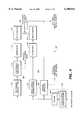
- FIG. 1is a functional block diagram showing an environment for a first portion of a system employing the encoding and decoding aspects of the invention.
- FIGS. 2 and 3are functional block diagrams showing an environment for alternative second portions of a system employing the encoding and decoding aspects of the invention.
- FIG. 4is a functional block diagram showing an embodiment of the encoder of the present invention being fed by an HDTV camera and an optional downconverter.
- FIG. 5is a functional block diagram showing a time-domain lowpass filter usable in the encoder of FIG. 4.
- FIG. 6is a functional block diagram of a decoder according to a preferred embodiment of the invention.
- FIG. 7is a partly schematic diagram showing the details of the combiner of FIG. 6.
- FIG. 8is a functional block diagram showing the details of a preferred field-based motion detector arrangement for use in the decoder of FIG. 6.
- FIG. 8Ais a quasi-three-dimensional representation of three consecutive interlaced-scan television fields, showing relative pixel locations within the respective fields.
- FIG. 9is a functional block diagram showing a preferred field-based motion detector for use in the arrangement of FIG. 8.
- FIG. 10is a functional block diagram showing a preferred frame motion detector for use in the decoder of FIG. 6.
- FIG. 11is a functional block diagram showing details of the pseudo-film pattern detector of the decoder of FIG. 6.
- FIG. 12is a functional block diagram showing an alternative arrangement for a portion of the pseudo-film detector of FIG. 11.
- signal inputs and outputsare drawn as single points and signal carrying lines are drawn as single lines. It will be understood that, in practice, more than one input or output point and more than one signal carrying line may be required, depending on the format of the signals and the manner in which the practical embodiments of the invention are physically constructed.
- FIGS. 1-3Useful environments for the various aspects of the present invention are shown in FIGS. 1-3.
- FIG. 1shows an environment for a first portion of a system employing the encoding and decoding aspects of the invention.
- an HDTV (high-definition television) camera 10provides a video source signal.
- the camera outputis applied to an optional downconverter 12.
- Either the camera output itself, if in a suitable format, or the downconverteris applied to an encoder 14 according to the present invention.
- the output of the downconverter or the output of the HDTV cameraprovide a progressively-scanned television signal having substantially the number of active picture scanning lines in a frame as the interlaced SDTV signal provided by the encoder 14 has in a frame (i.e., a frame made up of two interlaced fields) and having a progressive scan frame rate substantially the same as the interlaced field rate of the SDTV signal provided by the encoder.
- a framei.e., a frame made up of two interlaced fields
- a progressive scan frame ratesubstantially the same as the interlaced field rate of the SDTV signal provided by the encoder.
- any differences in aspect ratiomay be handled by an appropriate scaler which may be part of the optional downconverter.
- the desired output of encoder 14is an NTSC television signal having 525 lines (nominally 480 active picture lines), 2-1 interlaced, a nominal 60 Hz field rate (as is well known, the actual NTSC color frame rate is 59.94 Hz, however, it will be referred to as 60 Hz in this document and likewise, the 29.97 Hz field rate will be referred to as 30 Hz), and a nominal 30 Hz frame rate
- the input to the encodershould be a non-interlaced progressive scan television signal having a nominal 60 Hz frame rate and 480 active picture lines.
- the optional downconverter 12is employed. Downconverter 12 should satisfy the Nyquist criteria in all three dimensions (horizontal, vertical and temporal) in order to minimize artifacts in the ultimately reproduced television picture.
- the input signalmay be a monochrome video signal or the luminance components of a component color video signal.
- a component video signalmay comprise analog or digital components such as RGB (from which luminance and chrominance components may be derived), Y/I/Q, Y/U/V, Y/R-Y/B-Y, Y/Cr/Cb, etc.
- the received digital component video signalmay be in any of a number of compressed or uncompressed formats, including, for example, various ones of the digital component video formats in accordance with the recommendations, standards or compression algorithms of the CCIR (International Radio Consultative Committee) (such as the hierarchy of digital video coding formats under CCIR Recommendation 601, the 4:2:2 format often being referred to as a CCIR 601 video signal), ISO/MPEG (the Motion Picture Experts Group of the International Standards Organization), SMPTE (Society of Motion Picture and Television Engineers), EBU (European Broadcasting Union), and/or the recommendations or standards of other industry, governmental or quasi-governmental bodies.
- CCIRInternational Radio Consultative Committee
- ISO/MPEGthe Motion Picture Experts Group of the International Standards Organization
- SMPTESociety of Motion Picture and Television Engineers
- EBUEuropean Broadcasting Union
- the output of the encoder 14is then employed by a conventional television "studio" 16 which operates in accordance with the interlaced SDTV signal provided by the encoder.
- the studio 16may include, for example, television production, recording and/or editing facilities.
- the studio 16may also receive interlaced SDTV signals from video sources and motion picture film sources not processed by an encoder of the present invention.
- the output of the conventional studio 16 in the FIG. 1 arrangementmay be used to provide an interlaced SDTV signal to be used in a conventional way as, for example, for standard NTSC transmission or recording.
- the output of the conventional studiomay advantageously be employed as part of a system employing a decoder according to the present invention.
- FIGS. 2 and 3show alternative environments for completing such a system.
- the interlaced SDTV signal output of the conventional studio 16is upconverted to any desired HDTV format in block 20 and the signal is then applied to a transmission block 22.
- the transmission blockmay include wired and/or wireless transmission and/or recording.
- the transmission outputis then applied to a viewer's HDTV television set 24, operating in accordance with the HDTV format of block 20.
- Upconverter 20includes a decoder according to the present invention.
- the output of the conventional studio 16is applied to a transmission block 30.
- the transmission blockmay include both wired and/or wireless transmission and/or recording.
- the transmission outputis then applied to an upconverter 32 which upconverts the compatible standard-bandwidth television signal to any desired HDTV format in block 32.
- the HDTV signalis then applied to a viewer's HDTV television set 34, operating in accordance with the HDTV format of block 32.
- the transmission blockcarries an HDTV signal whereas in the arrangement of FIG. 3, the transmission block carries an interlaced SDTV signal.
- FIG. 4a functional block diagram, shows an embodiment of the encoder of the present invention being fed by an HDTV camera and an optional downconverter.
- the output of an HDTV camera(not shown) is applied to the optional downconverter 402.
- the downconverter 402may include a space-domain lowpass filter (typically, a vertical-domain lowpass filter) 404 and a scaler 406.
- the camera output or the downconverter outputif a downconverter is required, is applied to the encoder, shown here as the remaining portion 407 of FIG. 4.
- Such techniques and requirementsare well known in the prior art. See, for example, the Wendland and Tonge references cited above.
- the substantially alias-free progressively-scanned television signalis applied to three paths--two signal processing paths and a control signal generating path.
- the upper signal processing path 408is a low-motion signal processor providing a first intermediate interlaced television signal having low motion content.
- the lower signal processing path 410is a high-motion signal processor providing a second intermediate interlaced television signal having high motion content.
- the low-motion signal processor in path 408includes a time-domain lowpass filter 412.
- this temporal filteraverages two successive frames.
- the inputis applied to a one-frame delay 502 and to a summing node 504 which also receives the one-frame delayed output of the input signal.
- the output of the summing node 504is then scaled in amplitude by one-half in scaler 506.
- four successive framesmay be averaged.
- filter 412has a threshold such that it does not operate on signals below a certain amplitude level, for example, a level commensurate with the noise level.
- the purpose of the temporal filter 412is to provide greater adherence to the Nyquist criterion in the time domain.
- temporal aliasing artifactsare visible for some camera conditions.
- the slow panning of a scenemay cause a visible "juddering" effect.
- Another purpose for temporal filteris to provide a good balance between the signal processing timings of the paths 408 and 410.
- the output of the temporal filter 412remains a progressively-scanned television signal with the same frame rate and number of active picture lines as the input signal. This provides the same sharp image for still or slow moving objects as does the input signal to the time-domain lowpass filter.
- the temporal filter 412In order for the low-motion process of path 408 to provide a reasonable picture content alignment with the fields produced by the high-motion process of path 410, the temporal filter 412 must process an even number of frames (i.e., 2, 4, etc.). In practice, a two frame averaging is preferred, although averaging over four frames is practical although at greater cost and complexity.
- the temporal lowpass filter 412may also be adaptive such that it varies the number of frames over which it averages in response to the content of one or more frames.
- the output of the temporal filter 412is applied to a drop-frame-and-repeat function 414 which eliminates every other progressively-scanned frame and repeats every non-eliminated frame thereby providing pairs of processed identical progressively-scanned television signal frames having the same frame rate as the progressively-scanned television signal received by time-domain lowpass filter 412 but having a motion resolution of one-half its progressive scan frame rate.
- the signal at the output of block 414is equivalent to that which would result if the source were a film source having a frame rate half of the frame rate of the progressively-scanned signal--every two successive frames are identical (e.g., a 30 frame/second motion picture film in a 60 Hz NTSC system or a 25 frame/second motion picture film in a 50 Hz PAL system).
- block 414provides a field merge signal indicating which pairs of frames are identical.
- a marker signalis usable in the decoder to identify which pair of fields of the interlaced signal received at the decoder should be merged to reconstruct the progressively-scanned signal.
- the decodercould be simplified and there would be no need to transmit a marker signal (the decoder would simply employ well-known techniques to identify the even and odd parity fields making up each interlaced frame).
- the decoderis capable, albeit with greater complexity, of determining which pair of fields should be merged without receipt of a marker signal or the adoption of such a convention.
- the output of the drop-frame-and-repeat process 414is applied to an interlacer 416 providing an interlaced television signal having substantially the number of active picture scanning lines in a frame (i.e., two interlaced fields) as the processed progressively-scanned television signal has in a frame and having an interlaced field rate substantially the same as the frame rate of the processed progressively-scanned television signal.
- the interlacercreates the two opposite parity fields of each interlaced frame (or, alternatively, the two successive opposite parity fields from different interlaced frames) from each pair of identical progressively-scanned frames, dropping every other line in the pairs of identical progressively-scanned frames, the dropped lines being offset by one line from frame to frame.
- Such interlacersare known in the prior art in connection with converting motion picture film to video (i.e., the telecine art).
- the motion content or motion resolution of the resulting interlaced signalis at the interlaced frame rate rather than the field rate because each pair of fields is derived from a pair of identical progressively-scanned frames.
- the interlacer 416 outputis applied to a delay match 418 which provides any time delay necessary to synchronize the timing of the signal outputs from paths 408 and 410.
- the high-motion signal processor in path 410includes a space-domain lowpass filter 420.
- the space-domain filterprovides vertical-domain filtering by taking a weighted average of five successive horizontal lines, although this is not critical.
- Such filtersare well known in the art.
- the purpose of such a filteris to suppress a type of aliasing, the perceived flickering caused of single horizontal lines when they are moving vertically or the horizontal edges of objects when they are moving vertically.
- the space-domain lowpass filtermay also include a horizontal lowpass filter in order to further reduce aliasing artifacts caused by horizontal motion.
- filter 420has a threshold such that it does not operate on signals below a certain amplitude level, for example, a level commensurate with the noise level.
- the space-domain lowpass filter 420is applied to an interlacer 422 providing an interlaced television signal having substantially the number of active picture scanning lines in a frame (i.e., two interlaced fields) as the space-domain lowpass filtered progressively-scanned television signal has in a frame and having an interlace field rate substantially the same as the frame rate of the space-domain lowpass filtered progressively-scanned television signal.
- interlacer 422creates the two opposite parity fields of each interlaced frame from consecutive pairs of space-domain lowpass filtered progressively-scanned frames, wherein the interlacer drops every other line in the progressively-scanned frames to create each field, the dropped lines being offset by one line from frame to frame.
- interlacer 416Unlike in interlacer 416 in the low-motion path, the consecutive pairs of progressively-scanned frames, from which the pairs of interlaced fields are derived by interlacer 422, are not always identical.
- the motion content or motion resolution of the resulting interlaced signalis at the interlaced field rate because each field in a pair is derived from a different progressively-scanned frame.
- Interlacerssuch as interlacer 422 are known in the art.
- the interlacer 422 outputis applied to a delay match 424 which provides any time delay necessary to synchronize the timing of the signal outputs from paths 408 and 410.
- the outputs of the respective processor paths 408 and 410are applied to inputs of a type of switch 426, often referred to as a fader or soft switch, shown schematically as a potentiometer, the output of which, the interlaced SDTV signal output, is taken from the adjustable tap.
- a type of switch 426often referred to as a fader or soft switch, shown schematically as a potentiometer, the output of which, the interlaced SDTV signal output, is taken from the adjustable tap.
- the position of the tap, and therefore the degree to which the output of one path or another or some mixture of the two is taken as the encoder output,is controlled by a motion control signal produced by a motion control generator 428.
- the motion control signalis derived from differences in picture information from frame to frame of the progressively-scanned television signal input (the progressive scan frame rate being the same as the interlace scan field rate), the differences indicating the degree of motion in the progressively-scanned television signal (and consequently, in the resulting interlaced SDTV signal produced by the encoder). As the tap position is varied, the motion resolution of the resulting output signal varies.
- the switch 426may be implemented in any of various ways (electronically or by software, for example) which allow its rapid control such that changes in path selection within a field of the output interlaced signal are readily accomplished in real time.
- motion control generator 428detects differences between progressively-scanned frames on a pixel-by-pixel basis and generates a motion control signal responsive to differences in blocks of pixels from frame to frame in the input progressively-scanned signal.
- the motion control generatoris responsive to the velocity, size and amplitude of the picture movement.
- the motion control generatoris able to detect panning, where the entire picture (the entire frame) may be said to be moving.
- the motion control signalmay cause the switch to transition between the low-motion and high-motion mode outputs of paths 408 and 410 many times within each field, the extent to which one path or the other is selected depending on the degree of motion (based on a weighting of size, velocity and amplitude) throughout the picture.
- the motion control signalshould select the low motion path output when motion in the displayed picture would appear to the eye as smooth and continuous when displayed with the motion resolution produced by the low motion path; otherwise, it should select the high motion path output.
- the switchwill select the low-motion mode for at least a portion of each field (the entire field for the case of a still scene).
- the switchIn the very rare case of the HDTV camera source rapidly panning a still scene (for example, panning across the side of a mountain at a high motion rate (i.e., a rate greater than 30 Hz for NTSC), the switch would select the high-motion mode during the entire field.
- a pan of a running player in a football gamethe camera tracking the runner
- the motion control signal default conditionis such as to cause the switch 426 to select only the low-motion output of path 408.
- the motion control generator 428may also generate an optional pseudo-film YES/NO signal, the signal being in its YES condition for all conditions except when the entire field is in the high-motion mode.
- the output signal from switch 426is an interlaced signal having a baseline motion resolution at its frame rate, but in which high-motion "holes" occur within fields. Rarely, as just discussed above, entire fields have field rate motion, causing a break in the pseudo-film pattern.
- the result for most signal conditionsis pairs of interlaced fields which are derived at least in part from the same progressively-scanned frame: they are from the same progressively-scanned frame for those portions in which the field is produced by the low-motion process.
- Such an interlaced field pattern generated by the encoder of the present inventionis defined herein as a "pseudo-film pattern.”
- FIG. 6shows a functional block diagram of a decoder according to a preferred embodiment of the invention.
- the decoderforms a portion of the "Upconvert to HDTV Format" block 20 of the FIG. 2 arrangement or the "Upconvert to HDTV Format” block 32 of the FIG. 3 arrangement.
- the input of the FIG. 6 decoderis the input to block 20 (FIG. 2) or block 32 (FIG. 3), namely a interlaced SDTV signal.
- a reconstructed progressive scan television signalhas substantially the number of active picture scanning lines in a frame as the interlaced SDTV signal has in a frame (i.e., two interlaced fields) and has a progressive scan frame rate substantially the same as the interlace field rate of the interlaced television signal.
- the encoder outputis further upconverted, for example, by increasing the number of progressive scan lines or frames and/or changing the aspect ratio. Such further upconversion may be accomplished by any of various known techniques.
- Path 602includes a 24 Hz film source video processor 612.
- Elements related to processor 612include, in control signal path 610, a field- or frame-based motion detector 614 and a 24 Hz film pattern detector 616.
- Motion detector 614detects motion between fields or frames of the input interlaced SDTV signal and sends a signal responsive to such motion to a 24 Hz film pattern detector 616.
- a field-based motion detectoris preferred.
- Frame-based motion detectorsare well known in the art.
- the 24 Hz film pattern detector 616generates a field merge signal which is applied to the 24 Hz film source video processor 612 and a pattern YES/NO signal which controls switch 618. When a 24 Hz film pattern is detected, the film YES condition causes switch 618 to select the output the 24 Hz film source video processor as the decoder output.
- Film pattern detector 616looks for the pattern caused by a 24 Hz (24 frame/sec) motion picture film source in a 60 Hz NTSC signal.
- the detection of 3-2 pulldown 24 Hz film patterns in 60 Hz video signalsis well known in the art. See, for example, said U.S. Pat. Nos. 4,876,596; 4,982,280; and 5,291,280.
- a 50 Hz PAL format input signalwhich may carry 25 Hz (25 frame/sec) motion picture sources
- the 24 Hz film pattern detector 616, the 24 Hz film source video processor 612 and the switch 618are not required.
- the detection of 25 Hz film sources in 50 Hz PAL signalsmay be detected by the same decoder elements, described below, which detect a pseudo-film pattern in a 50 Hz PAL signal.
- the film source video processing provided by processor 612may be any known processing techniques for deriving progressively-scanned video signals from an interlaced film-source video signal, including, for example, any of the techniques disclosed in said three United States patents, cited just above.
- the output of a combiner 620which receives the outputs of paths 604 and 606 as its inputs, is selected as the decoder output.
- a field-based motion detector 622detects motion between fields and produces two motion signals, one responsive to high motion and another responsive to low motion. Details of such a motion detector are set forth below in connection with FIG. 8.
- the field motion signal from the field-based motion detector 622is applied to a pseudo-film pattern detector 624.
- a field-based motion detectoris required to detect a pseudo-film pattern.
- the pseudo-film detectorlooks for a pattern similar to that which would be caused by a 30 Hz (30 frame/sec) motion picture film source.
- the pseudo-film detectorlooks for a pattern similar to that which would be caused by a 30 Hz (30 frame/sec) motion picture film source.
- the pseudo-film detectorlooks for a pattern similar to that which would be caused by a 30 Hz (30 frame/sec) motion picture film source.
- the pseudo-film detectorlooks for a pattern similar to that which would be caused by a 30 Hz (30 frame/sec) motion picture film source.
- the pseudo-film detectorlooks for a pattern similar to that which would be caused by a 30 Hz (30 frame/sec) motion picture film source.
- the video sequences in adjacent video fieldsare compared a 010101, etc. pattern results, indicating a pseudo-film source.
- the pseudo-film patterndiffers from a true film pattern in that there are portions of the pairs of fields derived from the same progressively-scanned frame which are not derived from the same progressively-scanned frame due to transient occurrences of high motion.
- a modified 30 Hz film detectormay be employed for the case of an NTSC signal input (or a modified 25 Hz film detector may be employed for the case of a PAL signal input).
- a 30 Hz film detectoris disclosed in said U.S. Pat. No. 4,982,280.
- a detector designed for film source detectionmay require some modification such that, in the case of NTSC, for example, it ignores areas of high motion within an otherwise low motion pattern.
- the detectorshould generate a pseudo-pattern YES condition signal in response to all fields in which any portion of the field includes only low motion.
- a thresholdintended to eliminate false indications due to noise
- the detectorshould generate a pseudo-pattern YES condition signal in response to all fields in which any portion of the field includes only low motion.
- almost all fieldsare part of a pseudo-film pattern and the pattern is broken only when a field having all high motion is detected, resulting, for example, from the camera source's fast panning of a fully still scene, which is very rare.
- Such motion detector and pattern detector action required to provide the necessary action in the decoderare not disclosed in said U.S. Pat. No. 4,620,225.
- the pseudo-film pattern detector 624 and the high-motion motion signal from motion detector 622control a switch or combiner 620 which selects either the output of a pseudo-film source video processor 626 or the output of a conventional video processor 628 or some combination of the two.
- the pseudo-film processor 626provides for decoding of a pseudo-film signal created by the encoder of the present invention, thereby creating an excellent reconstruction of the input to the encoder.
- the conventional video processing function 628allows a video signal created by a source other than the encoder of the present invention to be processed.
- the conventional video interlace-to-progressive scan converter 628may be any of various known interlace-to-progressive scan converters or de-interlacers (sometimes known as line doublers), preferably of the adaptive type which operates on an interfield basis (merging, for example, pairs of fields or a field with an average of the field occurring before and after it) for conditions of low motion and on an intrafield basis (creating new scanning lines by interpolation from lines within the same field).
- the pseudo-film processor 626is preferably an interlace-to-progressive field-merge-type de-interlacer, a type of line doubler (lines from pairs of interlaced fields are merged to produce the progressively scanned lines).
- line doublersare well known in the art. See, for example said U.S. Pat. Nos. 5,159,451 and 4,876,596 and said Published International Patent Application WO 94/30006.
- the function of the decoderis explained by reference to several paths, practical embodiments providing substantially the same functions and results may be implemented in other ways.
- the 24 Hz film pattern detector 616 and the pseudo-film pattern detector 624may be at least partially combined.
- portions of the pseudo-film source video processor 626 and the conventional video processor 628may be at least partially combined.
- portions of the field-based motion detector 622 and the field and/or frame-based motion detectormay be combined.
- the decoder outputmay also be applied to an optional upconverter 630 if it is desired to alter the encoder output to accommodate the HDTV format or other format of the viewer's television set.
- Upconverter 630may, for example, increase the number of progressive scan lines, increase the progressive frame rate, perform a progressive-to-interlace conversion to an interlaced HDTV format or alter the aspect ratio.
- FIG. 7Details of the combiner 620 are shown schematically in FIG. 7 as comprising a first switch 702 and a second switch in the nature of a fader or soft switch, depicted as a potentiometer 704.
- Switch 702is controlled by the pseudo-film pattern YES/NO signal such that a YES condition places the switch in its upper position in which it selects the tap of the potentiometer.
- a NO conditionplaces the switch in its lower position in which it selects the output of the conventional video processor 628 (FIG. 6).
- the high-motion motion signal from motion detector 622(FIG. 6) controls the position of the potentiometer tap and therefore the degree to which the output of one path or another or some mixture of the two is taken as the decoder output.
- the potentiometer 704functions as a fader or soft switch.
- the switchmay be implemented in any of various ways (electronically or by software, for example) which allow its rapid control such that changes in path selection within a field are accomplished in real time. It should also be understood that in practice, the functions of switches 708 and 710 may be combined.
- the input signal designated "Y in "is applied to an array of field and line memories 802.
- the array of memories 802provides three outputs comprising time-delayed versions of Y in , which, along with Y in itself, provide four time-spaced versions of the input luminance signal: one in a first television field F0, two in a second television field F1 and one in a third television field F2.
- FIG. 8Ais a quasi-three-dimensional representation in which the vertical and horizontal dimensions lie in the plane of a television picture field such that the vertical axis is the vertical direction of a television picture field, perpendicular to the scan lines, the horizontal axis is the horizontal direction of the television picture field, parallel to the scan lines, and the direction perpendicular to the plane of each field is a quasi-time axis in which each consecutive field is shown at a discrete time.
- a pixelmay be represented as point P(F0) in field F0. That pixel is shown in FIG. 8A as a point in a horizontal scan line.
- a first pixel in field F1, occurring 262 lines (in the case of NTSC, for PAL, 312 lines) after pixel P(F0), and a second pixel in field F1, occurring 263 lines (in the case of NTSC, for PAL 313 lines) after pixel P(F0),may referred to as pixel P(F1-1/2H) and pixel P(F1+1/2H), respectively.
- Pixel P(F1-1/2H)shown as a point in a first horizontal scan line, is directly above pixel P(F1+1/2H) vertically, which pixel is shown as a point in the next lower horizontal scan line.
- a point P(F1) in field F1corresponding spatially to the location in which pixel P(F0) of field F0 lies, is half way between pixel P(F1-1/2H) and pixel P(F1+1/2H) due to the interlacing offset of horizontal scan lines from field to field.
- pixel P(F1-1/2H)precedes, by the time of one-half line, the point P(F1), while pixel P(F1+1/2H) is, by the time of one-half line, after the point P(F1).
- the spatial point in field F2 corresponding to that of pixels P(F0) and P(F1)is the location of pixel P(F2), occurring 525 lines, exactly one frame or two fields, after pixel P(F0).
- Pixel P(F2)is shown as a point in a horizontal scanning line in field F2.
- the undelayed input luminance signal stream Y initself provides the F0 output stream.
- the input luminance signal stream Y inis applied to a first nH delay 804 (where n is 262 lines for NTSC, 312 lines for PAL) to provide the F1-1/2H output stream.
- the output of delay 804is applied to a 1H (one horizontal line) delay 806 to provide the F1+1/2H output stream.
- the delay 806 outputis applied to a further nH delay (where n is 262 lines for NTSC, 312 lines for PAL) 808 to provide the F2 output stream.
- the delaysmay be implemented by various hardware, software and hybrid hardware/software techniques well known to those of ordinary skill in the art. Although shown as a series of delays, the delays may be implemented in other ways such as by a multiport random access memory in which the signal stream is read in once and read out multiple times, or by other equivalent ways.
- the array of memories 802provides four signal output streams corresponding to four pixel locations in three consecutive fields: a pixel at time position F0 in field 0, pixels at time positions F1-1/2H and F1+1/2H in field F1, and a pixel at time position F2 in field 2.
- a field 0 motion detector 814receives the F0, F1-1/2H and F1+1/2H signal streams, signals spaced apart in time by one field minus one-half line and by one field plus one-half line. It is known to apply such inputs to field motion detectors--see, for example, U.S. Pat. Nos. 4,982,280 and 5,291,280.
- the purpose of the field motion detectoris to detect motion (having a velocity greater than, for example, one half line per field) from interlaced field to interlaced field without falsely detecting motion when a vertical transition occurs (for example, when the portion of the picture below a horizontal line is black and the portion of the picture above the line is white, or vice-versa).
- the output of the field 0 motion detector 814, F0 mtnwhich, in a digital embodiment is a multibit word indicating motion amplitude, provides a field to field motion signal which is applied to the pseudo-film pattern detector 624 (FIG. 6).
- the F0 mtn signalis also used as one of two signals for deriving a high-motion motion signal, as described below.
- a second field motion detector, field 2 motion detector 816receives the F2, F1-1/2H and F1+1/2H signal streams, signals also spaced apart in time by one field minus one-half line and by one field plus one-half line.
- the output of the first field motion detectormay be delayed by one field (in practice, by one field plus or minus a half line).
- the output of the field 2 motion detector 816, F2 mtnwhich, in a digital embodiment is a multibit word indicating motion amplitude, also provides a field to field motion signal which is, with the F0 mtn signal, usable to derive a high-motion motion signal, as described below.
- the F2 mtn signalmay be used, in the manner described below, to verify the pseudo-film pattern detected using the F0 mtn signal.
- Motion detectors 814 and 816compare corresponding pixels in three successive fields, P(F0), P(F1) and P(F2) (it being understood that due to the interlace offset, in the middle field pixels just above and just below the picture location corresponding to pixels P(F0) and P(F2) are employed). There are four possibilities with respect to the three pixels:
- Case oneindicates no motion. Cases two and three indicate low motion and case four indicates high motion. Thus, a Boolean exclusive-OR function indicates low motion and a Boolean AND function indicates high motion as illustrated in the following table:
- the Boolean AND function operating on the resulting binary signalsgenerates an indication of high motion conditions. That indication may be used to select either the F0 mtn signal or the F2 mtn signal which has the greater amplitude or some combination of the two signals (such as their average amplitude) to produce the high motion signal for control of combiner 620 (FIG. 6).
- the F0 mtn signal, the F2 mtn signal and the resulting high motion signalindicate the motion amplitude and, in a digital implementation, are multibit words.
- a logic function 818provides such appropriate Boolean AND and selection or combining functions.
- the high motion control signalcauses the combiner 620 (FIG. 6) to select only the pseudo-film source video processor 626 output.
- the Boolean AND functionis one, indicating the third case, the high motion control signal causes the fader or soft switch function of the combiner 620 to swing between the pseudo-film and conventional processors in accordance with the amplitude of the motion (greater motion moving the fader toward the conventional video processor output).
- logic 818includes an Exclusive-OR function responding to binary-converted forms of the F0 mtn and F2 mtn signals
- a further signalmay be provided to verify the pseudo-film mode condition.
- this further signalmay be used to in conjunction with a modified pseudo-film pattern detector.
- the detectorcould be modified, for example, to identify a field as a pseudo-film field so long as the field did not contain any occurrences of the fourth condition (i.e., P(F0) ⁇ P(F1) ⁇ P(F2)).
- the field-based motion detector 622may be used in place of the field or frame-based motion detector 614 (FIG. 6), in which case the F0 mtn signal (FIG. 8) is applied to the 24 Hz film pattern detector 616 (FIG. 6) and to the conventional video processor 628 (FIG. 6).
- the decodermay receive a pseudo-film YES/NO signal, a field merge signal, and/or a high-motion signal from the encoder.
- a pseudo-film YES/NO signale.g., a pseudo-film YES/NO signal
- a field merge signale.g., a field merge signal
- a high-motion signale.g., a high-motion signal
- FIG. 9Details of the field motion detectors of FIG. 8 are shown in FIG. 9 (a single field motion detector as shown in FIG. 8, along with the appropriate delay memories may be used as motion detector 614).
- Each field motion detectorcompares temporally adjacent pixel information of opposing field parity (field 0 and field 1, for example) and differentiates field-to-field motion from vertical picture transitions to provide a field motion signal.
- Each field motion detectorincludes three subtractors (902, 904 and 906), a keep-smaller-absolute-value function 908, a magnitude comparator 910, and a motion/no-motion switch 912.
- Subtractor 902receives the F1-1/2H and F0 signals.
- Subtractor 904receives the F0 and F1+1/2H signals.
- Subtractor 906receives the F1-1/2H and F1+1/2H signals.
- the field motion detector described in U.S. Pat. No. 5,291,280employs subtractors 902 and 904, receiving the same inputs as just described, and the keep-smaller-absolute-value function 908.
- the field motion detectors of the present inventionmay use the same keep-smaller-absolute-value function arrangement as in said U.S. Pat. No. 5,291,280.
- Inter-field subtractionsyield field motion but also incorrectly detect vertical transitions as motion.
- the keep-smaller-absolute-value functionchooses the smaller of the two inter-field subtractions and thereby differentiates high frequency vertical transitions from motion.
- this preferred field motion detectoradds a single line vertical differentiator (the third subtractor 906), whose output, a measure of vertical energy, is compared in magnitude comparator 910 to the output of the keep-smaller-absolute-value function 908, an measure of field motion.
- Subtractor 906functioning as a single line vertical differentiator, looks for a vertical transition within a field.
- FIG. 6A preferred form of a frame motion detector for use as motion detector 614 (FIG. 6) (if a frame motion detector is used instead of a field motion detector) is shown in detail in FIG. 10, in which F0 and F2 video stream signals are compared on a pixel by pixel basis to determine if the corresponding pixel in field F1 is likely to be in motion.
- a one frame memory delay(not shown) is used to provide the F2 video stream signal.
- the subtractor 1002 outputis then put through complementary lowpass and highpass filters created by a lowpass filter 1004 and subtractor 1006.
- the lowpass filtermay be a five-tap FIR filter with a zero at the color subcarrier frequency (in a frame detector intended for use with both NTSC and PAL, the filter characteristics may be switchable in accordance with whether an NTSC or PAL signal is being processed).
- the horizontal lowpass filtered path (where most of the motion lies) on line 1008is rectified in rectifier 1010, and applied to a threshold function 1012 which removes noise components by applying a motion LPF noise threshold.
- the threshold 1012may, for example, limit the signal to four bits (from, say, eight bits).
- the horizontal highpass filtered path on line 1014goes into complementary vertical lowpass and highpass filters created by subtractor 1016, adder 1018 and delay 1020 (which provides a one-line delay for NTSC and a two-line delay in PAL).
- These paths, vertical HPF path 1022 and vertical LPF path 1024,are then individually rectified in rectifiers 1026 and 1028, respectively, and have their own thresholds (threshold functions 1030 and 1032, respectively, which remove noise components by applying a motion HHPF-VHPF Noise threshold and a motion HHPF-VLPF Noise threshold, respectively) (where HHPF is horizontal highpass filter, etc.).
- the thresholds 1030 and 1032may also limit the respective signals to 4 bits.
- three pathsare provided: a horizontally lowpass filtered (HLPF) path, a horizontally highpass filtered and vertically highpass filtered (HHPF-VHPF) path, and a horizontally highpass filtered and vertically lowpass filtered (HHPF-VHPF) path.
- the purpose of three pathsis to separate color subcarrier signal components from true motion information.
- the HLPF path outputhas substantially no subcarrier signal components as a result of the horizontal lowpass filtering action of LPF 1104.
- the two HHPF paths, carrying the complement of the HLPF pathrequire vertical filtering to reduce the subcarrier signal components present in the high-frequency portion of the spectrum. Such components have the appearance of a vertical line pattern which may occur in real television scenes.
- the filtering action of the HHPF-VHPF pathpasses low amplitude level subcarrier signal components.
- the filtering action of the HHPF-VLPF pathrejects subcarrier components (which have a vertical component because they are out-of-phase from line to line) but passes horizontally moving patterns of lines (referred to as "moving multiburst") which must be detected as motion (such a pattern is rejected by the other two paths).
- the HHPF-VLPF pathmay have a lower threshold level than does the HHPF-VHPF path because the HHPP-VLPF path is not differentiating desired from undesired signal components based on amplitude.
- the HLPF and HHPF-VLPF threshold levelsare selected for noise immunity.
- the three differently filtered motion pathsare then combined in summer 1034 and expanded in expansion function 1036.
- theyare expanded horizontally by 5 pixels, temporally by 1 field and vertically by 1 line.
- Techniques for such horizontal, vertical and temporal expansionare known. See for example, said U.S. Pat. No. 5,488,422.
- the output of block 1036is applied to one input of a keep greater value function 1038 and to a 262H/312H (262 lines for NTSC, 312 lines for PAL) delay 1040, the output of which is applied as a second input to block 1038, and to a 1H (one line) delay 1042, the output of which is applied as a third input to block 1038.
- Blocks 1036-1042provide a temporally and vertically expanded motion signal.
- temporal and vertical expansionare twofold--to avoid the situation when a fast moving object leaves a "hole” between frames (e.g., a swinging pendulum) and, in the case of an NTSC signal, to avoid an appearance of fluttering between sharp and soft pictures when film material is not detected as film material. Also, expansion assures that the frame motion signal "surrounds" the field motion signal in the pseudo-film detector.
- the frame motion detectorhas three adjustable parameters: the motion LPF noise threshold, the motion HHPF-VLPF noise threshold, and the motion HHPF-VHPF noise threshold.
- the parametersshould be adjusted to as to minimize false detection of motion caused by noise and subcarrier signal components.
- the purpose of the pseudo-film pattern detector 624is to determine the onset of a pseudo-film pattern, thus entering the pseudo-film mode (indicated by putting the pseudo-film YES/NO signal in its YES condition), and, after entering the pseudo-film mode, when the pseudo-film pattern is broken, exiting the pseudo-film mode (indicated by putting the pseudo-film YES/NO signal in its NO condition).
- the pseudo-film pattern detector 624receives the field motion signal from field-based motion detector 622.
- the pseudo-film pattern detectoris basically the same as a PAL film detector, which looks for 25 Hz sources in a 50 Hz television signal or an NTSC 30 Hz film detector, which looks for 30 Hz sources in a 60 Hz television signal.
- a field-based film detector for detecting 25 frame/second motion in PAL television signalsis disclosed in said Published International Patent Application WO 94/30006, while a field-based film detector for detecting 30 frame/second motion in NTSC television signals is disclosed in said U.S. Pat. No. 4,982,280.
- the pseudo-film detectorexamines the accumulated field motion between field 0 and field 1 and then searches for the 30 Hz (30 Hz for NTSC, 25 Hz for PAL) field motion pseudo-film sequence pattern "1 0" before determining if the material is pseudo-film and not other video.
- the pseudo-film detectorreceives the F0 mtn output signal of the field 0 motion detector 813 (FIG. 8).
- the field motion signalis filtered in low-pass filter 1102 to remove subcarrier residue, rectified in rectifier 1104, and blanked by pseudo-film motion blanking function 1106 to keep any picture edge artifacts and subtitles from being detected as motion.
- the rectified and blanked motion signalis then applied to a threshold 1108 to reduce noise artifacts.
- the thresholdis set by a fixed and predefined pseudo-film noise threshold.
- the motion input from a frame motion detector(if used) is thresholded by a threshold 1110 into, in a digital implementation, a one-bit motion yes/no signal.
- This thresholdis set by a motion threshold.
- the one-bit motion yes/no signalis then used to control a motion-no motion switch 1112.
- the optional frame motion indicationserves as a verification of the field motion indication--if there is no frame motion at a given pixel then there cannot be any field motion for the same pixel (the frame motion has been expanded horizontally and vertically to assure that the band of frame motion surrounds the field motion).
- the one-bit field motion signal from switch 1112is then accumulated over the entire field in a field rate accumulator 1114.
- the recurring pseudo-film sequence "1 0"can occur on standard video material for a few frames in a row so care must be taken to differentiate pseudo-film source video from conventional video.
- the arrangement in the pseudo-film detector between the field rate accumulator 1114 and the state machine 1130may be modified by substituting the arrangement of FIG. 12, described below.
- the motion signis fed into the pseudo-film state machine 1150, which may be the same type of state machine as in said U.S. Pat. No. 4,982,280. If not, a 0 is input. Pseudo-film mode is entered once the number of film sequences reaches the pseudo-film sequence acquisition number. Exiting the pseudo-film mode occurs when the pseudo-film sequence is disrupted by a field in which the entire field is high motion.
- the pseudo-film detectorhas eight adjustable parameters: a pseudo-film noise threshold, a motion threshold, a pseudo-film sequence acquisition number, a minimum motion ratio and four pseudo-film blanking parameters that define the area of pseudo-film motion detection: pseudo-film blanking top line, pseudo-film blanking bottom line, pseudo-film blanking right side, and pseudo-film blanking left side.
- FIG. 12shows an alternative arrangement for a portion of the pseudo-film detector of FIG. 11.
- the datais latched in and the motion value is then passed from field rate accumulator 1114 (FIG. 11) into three parallel paths, 1216, 1218 and 1220: 1) path 1216 to a minimum of five field detector 1222 (although a minimum of five fields is preferred to provide a safety margin, a minimum of three fields is practicable), 2) path 1218 to a three field weighted averager 1224, and 3) path 1220 to one side of a subtractor 1226 where end-of-field calculations are performed.
- the accumulatorsare reset.
- the minimum-of-five field detector 1222looks at five adjacent fields for the minimum motion. For pseudo-film in five adjacent fields there will always be a non-moving field, and therefore the minimum motion value will correspond to it.
- This outputprovides the other input to the subtractor 1226 in order to remove the base motion value associated with a non-moving field from the accumulator 1214 output on path 1220.
- the subtractor 1226 outputis then passed to a variable threshold 1228 whose threshold is determined by the output of block 1224, the weighted average of three fields.
- the minimum motion detector 1222 and the weighted averager 1224greatly increase the sensitivity of pseudo-film detection on small moving scenes and factor out computer generated material which violates the Nyquist criterion.
- the output of the variable threshold 1228, a "1" for a moving field and a "0" for a non-moving field,is then fed into the state machine 1130 (FIG. 11).
Landscapes
- Engineering & Computer Science (AREA)
- Multimedia (AREA)
- Signal Processing (AREA)
- Computer Graphics (AREA)
- Television Systems (AREA)
Abstract
Description
______________________________________ Field 0- Field 1- Low MotionHigh Motion Field 1 Field 2 (Exclusive-OR) (AND) ______________________________________ 0 0 0 0 1 0 0 0 1 1 ______________________________________
Claims (22)
Priority Applications (5)
| Application Number | Priority Date | Filing Date | Title |
|---|---|---|---|
| US08/948,539US6108041A (en) | 1997-10-10 | 1997-10-10 | High-definition television signal processing for transmitting and receiving a television signal in a manner compatible with the present system |
| DE69840322TDE69840322D1 (en) | 1997-10-10 | 1998-10-06 | PROCESSING A TELEVISION SIGNAL HIGH RESOLUTION FOR TRANSMITTING AND RECEIVING A TELEVISION SIGNAL COMPATIBLE WITH THE PRESENT SYSTEM |
| PCT/US1998/021072WO1999020046A1 (en) | 1997-10-10 | 1998-10-06 | High-definition television signal processing for transmitting and receiving a television signal in a manner compatible with the present system |
| EP98949786AEP0945016B1 (en) | 1997-10-10 | 1998-10-06 | High-definition television signal processing for transmitting and receiving a television signal in a manner compatible with the present system |
| JP52227699AJP4294100B2 (en) | 1997-10-10 | 1998-10-06 | High-definition television signal processing for transmitting and receiving television signals in a manner compatible with current systems |
Applications Claiming Priority (1)
| Application Number | Priority Date | Filing Date | Title |
|---|---|---|---|
| US08/948,539US6108041A (en) | 1997-10-10 | 1997-10-10 | High-definition television signal processing for transmitting and receiving a television signal in a manner compatible with the present system |
Publications (1)
| Publication Number | Publication Date |
|---|---|
| US6108041Atrue US6108041A (en) | 2000-08-22 |
Family
ID=25487972
Family Applications (1)
| Application Number | Title | Priority Date | Filing Date |
|---|---|---|---|
| US08/948,539Expired - Fee RelatedUS6108041A (en) | 1997-10-10 | 1997-10-10 | High-definition television signal processing for transmitting and receiving a television signal in a manner compatible with the present system |
Country Status (5)
| Country | Link |
|---|---|
| US (1) | US6108041A (en) |
| EP (1) | EP0945016B1 (en) |
| JP (1) | JP4294100B2 (en) |
| DE (1) | DE69840322D1 (en) |
| WO (1) | WO1999020046A1 (en) |
Cited By (89)
| Publication number | Priority date | Publication date | Assignee | Title |
|---|---|---|---|---|
| US20010016010A1 (en)* | 2000-01-27 | 2001-08-23 | Lg Electronics Inc. | Apparatus for receiving digital moving picture |
| US6393079B1 (en)* | 1998-07-28 | 2002-05-21 | Motorola, Inc. | Transient-suppressing mode switch |
| US20020131499A1 (en)* | 2001-01-11 | 2002-09-19 | Gerard De Haan | Recognizing film and video objects occuring in parallel in single television signal fields |
| US20020135697A1 (en)* | 2001-01-11 | 2002-09-26 | Wredenhagen G. Finn | System and method for detecting a non-video source in video signals |
| US20020136305A1 (en)* | 2000-12-20 | 2002-09-26 | Samsung Electronics Co., Ltd. | Method of detecting motion in an interlaced video sequence based on logical operation on linearly scaled motion information and motion detection apparatus |
| US6489997B1 (en)* | 1998-04-29 | 2002-12-03 | John J. Stapleton | Versatile video transformation device |
| US6493041B1 (en)* | 1998-06-30 | 2002-12-10 | Sun Microsystems, Inc. | Method and apparatus for the detection of motion in video |
| US20030081144A1 (en)* | 2001-10-22 | 2003-05-01 | Nader Mohsenian | Video data de-interlacing using perceptually-tuned interpolation scheme |
| US20030099296A1 (en)* | 2001-11-28 | 2003-05-29 | Samsung Electronics Co., Ltd. | Film mode detecting apparatus and method thereof |
| US20030174246A1 (en)* | 2002-03-12 | 2003-09-18 | Via Technologies, Inc. | Method and device for processing image data from non-interlacing type into interlacing one |
| US20030174245A1 (en)* | 2002-03-12 | 2003-09-18 | Via Technologies, Inc. | Clock signal synthesizer with multiple frequency outputs and method for synthesizing clock signal |
| US20030174247A1 (en)* | 2002-03-12 | 2003-09-18 | Via Technologies, Inc. | Adaptive deflicker method and adaptive deflicker filter |
| US20030184662A1 (en)* | 2002-03-29 | 2003-10-02 | Gary Porter | Image capture apparatus |
| US20040008275A1 (en)* | 2002-07-13 | 2004-01-15 | Samsung Electronics Co., Ltd. | Apparatus for and method of detecting whether incoming image signal is in film mode |
| US20040057467A1 (en)* | 2002-09-23 | 2004-03-25 | Adams Dale R. | Detection and repair of MPEG-2 chroma upconversion artifacts |
| US20040114048A1 (en)* | 2002-12-16 | 2004-06-17 | Samsung Electronics Co., Ltd. | Image signal format detection apparatus and method |
| US20040119883A1 (en)* | 2002-12-20 | 2004-06-24 | Samsung Electronics Co., Ltd. | Image format conversion apparatus and method |
| US20040207754A1 (en)* | 2003-01-08 | 2004-10-21 | Choi Byung Tae | De-interlacing device of digital television set |
| US6822691B1 (en)* | 2000-12-20 | 2004-11-23 | Samsung Electronics Co., Ltd. | Method of detecting motion in an interlaced video sequence utilizing region by region motion information and apparatus for motion detection |
| US20050036061A1 (en)* | 2003-05-01 | 2005-02-17 | Fazzini Paolo Guiseppe | De-interlacing of video data |
| US20050105789A1 (en)* | 2003-11-17 | 2005-05-19 | Isaacs Hugh S. | Method and apparatus for detecting, monitoring, and quantifying changes in a visual image over time |
| US20050114890A1 (en)* | 2003-11-26 | 2005-05-26 | Wegener Communications, Inc. | Automated transport stream apparatus and method |
| US20050219410A1 (en)* | 2004-04-02 | 2005-10-06 | Kun-Nan Cheng | De-interlacing Device Capable of De-interlacing a Video Field Adaptively and Associated Method |
| US20050243923A1 (en)* | 2000-03-14 | 2005-11-03 | Victor Company Of Japan | Variable picture rate coding/decoding method and apparatus |
| US20060007354A1 (en)* | 2004-06-16 | 2006-01-12 | Po-Wei Chao | Method for false color suppression |
| US20060023818A1 (en)* | 2004-07-27 | 2006-02-02 | Lee Bong-Geun | Image enhancement apparatus and method in wireless system |
| US20060033839A1 (en)* | 2004-08-16 | 2006-02-16 | Po-Wei Chao | De-interlacing method |
| US20060095471A1 (en)* | 2004-06-07 | 2006-05-04 | Jason Krikorian | Personal media broadcasting system |
| US20060117371A1 (en)* | 2001-03-15 | 2006-06-01 | Digital Display Innovations, Llc | Method for effectively implementing a multi-room television system |
| US7064790B1 (en)* | 2001-05-14 | 2006-06-20 | Microsoft Corporation | Adaptive video data frame resampling |
| US20060158550A1 (en)* | 2005-01-20 | 2006-07-20 | Samsung Electronics Co., Ltd. | Method and system of noise-adaptive motion detection in an interlaced video sequence |
| US20070003224A1 (en)* | 2005-06-30 | 2007-01-04 | Jason Krikorian | Screen Management System for Media Player |
| US20070022328A1 (en)* | 2005-06-30 | 2007-01-25 | Raghuveer Tarra | Firmware Update for Consumer Electronic Device |
| US20070058087A1 (en)* | 2005-09-15 | 2007-03-15 | Kettle Wiatt E | Image display system and method |
| US20070064008A1 (en)* | 2005-09-14 | 2007-03-22 | Childers Winthrop D | Image display system and method |
| US20070063996A1 (en)* | 2005-09-14 | 2007-03-22 | Childers Winthrop D | Image display system and method |
| US20070064007A1 (en)* | 2005-09-14 | 2007-03-22 | Childers Winthrop D | Image display system and method |
| US20070168543A1 (en)* | 2004-06-07 | 2007-07-19 | Jason Krikorian | Capturing and Sharing Media Content |
| US20070198532A1 (en)* | 2004-06-07 | 2007-08-23 | Jason Krikorian | Management of Shared Media Content |
| US20070234213A1 (en)* | 2004-06-07 | 2007-10-04 | Jason Krikorian | Selection and Presentation of Context-Relevant Supplemental Content And Advertising |
| US20070252894A1 (en)* | 2006-04-27 | 2007-11-01 | Fujitsu Limited | Converting device and converting method of video signals |
| US20070258013A1 (en)* | 2004-06-16 | 2007-11-08 | Po-Wei Chao | Methods for cross color and/or cross luminance suppression |
| US20070279532A1 (en)* | 2005-05-31 | 2007-12-06 | Kabushiki Kaisha Toshiba | Pull-down signal detection apparatus, pull-down signal detection method and progressive-scan conversion apparatus |
| US20080059533A1 (en)* | 2005-06-07 | 2008-03-06 | Sling Media, Inc. | Personal video recorder functionality for placeshifting systems |
| US7356439B2 (en) | 2002-11-27 | 2008-04-08 | Samsung Electronics Co., Ltd. | Motion detection apparatus and method |
| US20080158414A1 (en)* | 2006-12-29 | 2008-07-03 | Texas Instruments Incorporated | Method for detecting film pulldown cadences |
| US20080256485A1 (en)* | 2007-04-12 | 2008-10-16 | Jason Gary Krikorian | User Interface for Controlling Video Programs on Mobile Computing Devices |
| US20080278631A1 (en)* | 2007-05-09 | 2008-11-13 | Hideki Fukuda | Noise reduction device and noise reduction method of compression coded image |
| US20090022408A1 (en)* | 2005-04-19 | 2009-01-22 | Matsushita Electric Industrial Co., Ltd. | Imiage processing apparatus and image processing program |
| US20090051809A1 (en)* | 2007-08-20 | 2009-02-26 | Marshall Charles Capps | System and Method for Combining Interlaced Video Frames |
| US7576802B1 (en)* | 2005-10-11 | 2009-08-18 | Segura Kevin T | Digital motion picture film enhancement approaches |
| US20090244093A1 (en)* | 2006-09-01 | 2009-10-01 | Zhi Bo Chen | Method and device for adaptive video presentation |
| US20100001960A1 (en)* | 2008-07-02 | 2010-01-07 | Sling Media, Inc. | Systems and methods for gestural interaction with user interface objects |
| US20100064332A1 (en)* | 2008-09-08 | 2010-03-11 | Sling Media Inc. | Systems and methods for presenting media content obtained from multiple sources |
| US7725912B2 (en)* | 1999-05-26 | 2010-05-25 | Sling Media, Inc. | Method for implementing a remote display system with transcoding |
| US20100265409A1 (en)* | 2007-11-06 | 2010-10-21 | Sharp Kabushiki Kaisha | Film mode determination apparatus and determination method |
| US20110013081A1 (en)* | 2001-01-11 | 2011-01-20 | Pixelworks, Inc. | System and method for detecting a non-video source in video signals |
| US20110035467A1 (en)* | 2009-08-10 | 2011-02-10 | Sling Media Pvt Ltd | Localization systems and methods |
| US20110153718A1 (en)* | 2009-12-22 | 2011-06-23 | Sling Media Inc. | Systems and methods for establishing network connections using local mediation services |
| US20110158610A1 (en)* | 2009-12-28 | 2011-06-30 | Sling Media Inc. | Systems and methods for searching media content |
| US20110191456A1 (en)* | 2010-02-03 | 2011-08-04 | Sling Media Pvt Ltd | Systems and methods for coordinating data communication between two devices |
| US20110196521A1 (en)* | 2010-02-05 | 2011-08-11 | Sling Media Inc. | Connection priority services for data communication between two devices |
| US20110208506A1 (en)* | 2010-02-24 | 2011-08-25 | Sling Media Inc. | Systems and methods for emulating network-enabled media components |
| US8060609B2 (en) | 2008-01-04 | 2011-11-15 | Sling Media Inc. | Systems and methods for determining attributes of media items accessed via a personal media broadcaster |
| US8099755B2 (en) | 2004-06-07 | 2012-01-17 | Sling Media Pvt. Ltd. | Systems and methods for controlling the encoding of a media stream |
| US8171148B2 (en) | 2009-04-17 | 2012-05-01 | Sling Media, Inc. | Systems and methods for establishing connections between devices communicating over a network |
| US8314893B2 (en) | 2009-08-28 | 2012-11-20 | Sling Media Pvt. Ltd. | Remote control and method for automatically adjusting the volume output of an audio device |
| US8350971B2 (en) | 2007-10-23 | 2013-01-08 | Sling Media, Inc. | Systems and methods for controlling media devices |
| US8381310B2 (en) | 2009-08-13 | 2013-02-19 | Sling Media Pvt. Ltd. | Systems, methods, and program applications for selectively restricting the placeshifting of copy protected digital media content |
| US8406431B2 (en) | 2009-07-23 | 2013-03-26 | Sling Media Pvt. Ltd. | Adaptive gain control for digital audio samples in a media stream |
| US8438602B2 (en) | 2009-01-26 | 2013-05-07 | Sling Media Inc. | Systems and methods for linking media content |
| US8477793B2 (en) | 2007-09-26 | 2013-07-02 | Sling Media, Inc. | Media streaming device with gateway functionality |
| US8532472B2 (en) | 2009-08-10 | 2013-09-10 | Sling Media Pvt Ltd | Methods and apparatus for fast seeking within a media stream buffer |
| US8542319B1 (en)* | 2012-12-07 | 2013-09-24 | Faroudja Enterprises, Inc. | Interlaced video pre-processor |
| US8667279B2 (en) | 2008-07-01 | 2014-03-04 | Sling Media, Inc. | Systems and methods for securely place shifting media content |
| US8667163B2 (en) | 2008-09-08 | 2014-03-04 | Sling Media Inc. | Systems and methods for projecting images from a computer system |
| US20140104381A1 (en)* | 2009-02-05 | 2014-04-17 | Bitanimate, Inc. | Two-dimensional video to three-dimensional video conversion method and system |
| US8799485B2 (en) | 2009-12-18 | 2014-08-05 | Sling Media, Inc. | Methods and apparatus for establishing network connections using an inter-mediating device |
| US8966101B2 (en) | 2009-08-10 | 2015-02-24 | Sling Media Pvt Ltd | Systems and methods for updating firmware over a network |
| US9015225B2 (en) | 2009-11-16 | 2015-04-21 | Echostar Technologies L.L.C. | Systems and methods for delivering messages over a network |
| US9160974B2 (en) | 2009-08-26 | 2015-10-13 | Sling Media, Inc. | Systems and methods for transcoding and place shifting media content |
| US9178923B2 (en) | 2009-12-23 | 2015-11-03 | Echostar Technologies L.L.C. | Systems and methods for remotely controlling a media server via a network |
| US9191610B2 (en) | 2008-11-26 | 2015-11-17 | Sling Media Pvt Ltd. | Systems and methods for creating logical media streams for media storage and playback |
| US9479737B2 (en) | 2009-08-06 | 2016-10-25 | Echostar Technologies L.L.C. | Systems and methods for event programming via a remote media player |
| US9491398B1 (en) | 2010-12-21 | 2016-11-08 | Pixelworks, Inc. | System and method for processing assorted video signals |
| US9525838B2 (en) | 2009-08-10 | 2016-12-20 | Sling Media Pvt. Ltd. | Systems and methods for virtual remote control of streamed media |
| US9565479B2 (en) | 2009-08-10 | 2017-02-07 | Sling Media Pvt Ltd. | Methods and apparatus for seeking within a media stream using scene detection |
| US9998802B2 (en) | 2004-06-07 | 2018-06-12 | Sling Media LLC | Systems and methods for creating variable length clips from a media stream |
| US10554964B1 (en)* | 2018-08-24 | 2020-02-04 | Rohde & Schwarz Gmbh & Co. Kg | Test system and method using detection patterns |
Families Citing this family (3)
| Publication number | Priority date | Publication date | Assignee | Title |
|---|---|---|---|---|
| GB9824061D0 (en) | 1998-11-03 | 1998-12-30 | Snell & Wilcox Ltd | Film sequence detection (nt4) |
| GB2358309A (en)* | 2000-01-11 | 2001-07-18 | Snell & Wilcox Ltd | Analysing motion between adjacent fields using weighted field difference |
| JP5932293B2 (en)* | 2011-10-31 | 2016-06-08 | キヤノン株式会社 | Image output device |
Citations (93)
| Publication number | Priority date | Publication date | Assignee | Title |
|---|---|---|---|---|
| US3832487A (en)* | 1971-12-21 | 1974-08-27 | Philips Corp | Method of converting image signals generated in a non-interlaced manner into image signals interlaced in accordance with a television standard |
| US4272787A (en)* | 1978-09-07 | 1981-06-09 | Micro Consultants Limited | T.V. Picture freeze system |
| US4298888A (en)* | 1979-06-08 | 1981-11-03 | Hughes Aircraft Company | Non-interlaced to interlaced format video converter |
| US4322750A (en)* | 1979-05-08 | 1982-03-30 | British Broadcasting Corporation | Television display system |
| US4386367A (en)* | 1981-06-26 | 1983-05-31 | Tektronix, Inc. | System and method for converting a non-interlaced video signal into an interlaced video signal |
| US4400719A (en)* | 1981-09-08 | 1983-08-23 | Rca Corporation | Television display system with reduced line-scan artifacts |
| US4435728A (en)* | 1981-02-09 | 1984-03-06 | U.S. Philips Corporation | Field frequency-doubling circuit for a television signal |
| US4531152A (en)* | 1979-10-03 | 1985-07-23 | Lemelson Jerome H | Television system and method |
| US4551753A (en)* | 1981-12-17 | 1985-11-05 | Nippon Hoso Kyokai | Picture signal processing system including spatio-temporal filter |
| US4620225A (en)* | 1982-09-13 | 1986-10-28 | Robert Bosch Gmbh | System for TV transmission |
| US4635114A (en)* | 1983-11-15 | 1987-01-06 | Robert Bosch Gmbh | Adaptive television transmission system |
| US4641188A (en)* | 1985-07-31 | 1987-02-03 | Rca Corporation | Progressive scan display system employing line and frame memories |
| US4651211A (en)* | 1986-01-17 | 1987-03-17 | Rca Corporation | Video signal motion detecting apparatus |
| US4652909A (en)* | 1982-09-14 | 1987-03-24 | New York Institute Of Technology | Television camera and recording system for high definition television having imagers of different frame rate |
| US4661850A (en)* | 1986-01-31 | 1987-04-28 | Rca Corporation | Progressive scan television system with interlaced inter-field sum and difference components |
| US4692801A (en)* | 1985-05-20 | 1987-09-08 | Nippon Hoso Kyokai | Bandwidth compressed transmission system |
| US4698675A (en)* | 1986-09-29 | 1987-10-06 | Rca Corporation | Progressive scan display system having intra-field and inter-field processing modes |
| US4709277A (en)* | 1984-03-28 | 1987-11-24 | Sony Corporation | Editing data converting apparatus |
| US4713688A (en)* | 1984-09-26 | 1987-12-15 | Ant Nachrichtentechnik Gmbh | Method for increasing resolution in a compatible television system |
| US4733299A (en)* | 1987-03-26 | 1988-03-22 | New York Institute Of Technology | Method and apparatus for generating progressively scanned television information |
| US4864398A (en)* | 1987-06-09 | 1989-09-05 | Sony Corp. | Motion vector processing in digital television images |
| US4897716A (en)* | 1986-12-02 | 1990-01-30 | British Broadcasting Corporation | Method and apparatus for adaptively displaying video signals |
| US4924306A (en)* | 1988-02-23 | 1990-05-08 | U.S. Philips Corporation | Method of and device for estimating the extent of motion in a picture element of a television picture |
| US4933759A (en)* | 1988-05-26 | 1990-06-12 | U.S. Philips Corporation | Method of and arrangement for motion detection in an interlaced television picture obtained after film-to-television conversion |
| US4935816A (en)* | 1989-06-23 | 1990-06-19 | Robert A. Faber | Method and apparatus for video image film simulation |
| US4937668A (en)* | 1988-03-15 | 1990-06-26 | Pioneer Electronic Corporation | Method and apparatus for transmitting video information |
| US4941045A (en)* | 1988-10-11 | 1990-07-10 | Scientific-Atlanta, Inc. | Method and apparatus for improving vertical definition of a television signal by scan conversion |
| US4959715A (en)* | 1989-06-16 | 1990-09-25 | North American Philips Corporation | Method and apparatus for converting an interlaced television transmission to a sequential display using maximum likelihood estimation |
| US4967271A (en)* | 1989-04-05 | 1990-10-30 | Ives C. Faroudja | Television scan line doubler including temporal median filter |
| US4979020A (en)* | 1987-09-14 | 1990-12-18 | General Electric Company | Television signal encoded with auxiliary vertical-temporal information |
| US4985767A (en)* | 1988-02-23 | 1991-01-15 | U. S. Philips Corporation | Spatio-temporal sub-sampling of digital video signals representing a succession of interlaced or sequential images, transmission of high-definition television images, and emission and reception stages for such a system |
| US4998287A (en)* | 1988-10-14 | 1991-03-05 | General Instrument Corporation | Determination of sequential positions of video fields derived from film |
| US4998167A (en)* | 1989-11-14 | 1991-03-05 | Jaqua Douglas A | High resolution translation of images |
| US5012326A (en)* | 1988-08-23 | 1991-04-30 | Kabushiki Kaisha Toshiba | Television signal transmitting and receiving system |
| US5019904A (en)* | 1989-12-04 | 1991-05-28 | Campbell Jack J | Scan converter with adaptive vertical filter for single bit computer graphics systems |
| US5023713A (en)* | 1989-04-24 | 1991-06-11 | Matsushita Electric Industrial Co., Ltd. | Motion detection circuit for use in a television |
| US5043810A (en)* | 1987-12-22 | 1991-08-27 | U.S. Philips Corporation | Method and apparatus for temporally and spatially processing a video signal |
| EP0446894A2 (en)* | 1990-03-14 | 1991-09-18 | Kabushiki Kaisha Toshiba | Television signal scanning line converting apparatus |
| US5081532A (en)* | 1990-08-30 | 1992-01-14 | Zenith Electronics Corporation | Adaptive progressive scan converter |
| US5115311A (en)* | 1989-11-14 | 1992-05-19 | Shell Oil Company | High resolution translation of images |
| US5128747A (en)* | 1988-02-29 | 1992-07-07 | General Electric Company | Television signal processing system for reducing diagonal image artifacts |
| US5134480A (en)* | 1990-08-31 | 1992-07-28 | The Trustees Of Columbia University In The City Of New York | Time-recursive deinterlace processing for television-type signals |
| US5136380A (en)* | 1989-12-28 | 1992-08-04 | Samsung Electronics Co., Ltd. | Display signal device and method for providing compatibility between ntsc television and hdtv |
| US5138449A (en)* | 1989-05-02 | 1992-08-11 | Michael Kerpchar | Enhanced definition NTSC compatible television system |
| US5146329A (en)* | 1990-03-09 | 1992-09-08 | Deutsche Itt Industries Gmbh | Apparatus and method for reducing line flicker in a television picture |
| US5153719A (en)* | 1990-08-22 | 1992-10-06 | U.S. Philips Corporation | Method of detecting horizontal movements in the picture contents of a television signal |
| US5174641A (en)* | 1990-07-25 | 1992-12-29 | Massachusetts Institute Of Technology | Video encoding method for television applications |
| US5177615A (en)* | 1990-01-31 | 1993-01-05 | Sony Corporation | Apparatus for recovering a film signal from a television video signal |
| US5191427A (en)* | 1990-08-29 | 1993-03-02 | Sony Broadcast & Communications Limited | Video post-production of material acquired on film |
| US5191413A (en)* | 1990-11-01 | 1993-03-02 | International Business Machines | System and method for eliminating interlace motion artifacts in captured digital video data |
| US5204745A (en)* | 1990-07-19 | 1993-04-20 | Nippon Television Network Corp. | High-definition television signal processing system for transmitting and receiving a television signal in a manner compatible with the present system |
| US5221966A (en)* | 1990-01-17 | 1993-06-22 | Avesco Plc | Video signal production from cinefilm originated material |
| US5227879A (en)* | 1990-01-26 | 1993-07-13 | Tokyo Broadcasting System Inc. | Apparatus for transmitting an extended definition TV signal having compatibility with a conventional TV system |
| US5235417A (en)* | 1992-03-26 | 1993-08-10 | Rca Thomson Licensing Corporation | Television signal scan conversion system with motion adaptive processing |
| US5255091A (en)* | 1989-10-20 | 1993-10-19 | Snell & Wilcox Limited | Digital television standards conversion |
| US5267035A (en)* | 1991-08-08 | 1993-11-30 | Samsung Electronics Co., Ltd. | Motion detection for video including that obtained from film |
| US5303045A (en)* | 1991-08-27 | 1994-04-12 | Sony United Kingdom Limited | Standards conversion of digital video signals |
| US5315327A (en)* | 1991-05-21 | 1994-05-24 | Sony Corporation | High scanning rate to standard scanning rate television signal converter with smooth moving edge conversion |
| US5317398A (en)* | 1992-08-17 | 1994-05-31 | Rca Thomson Licensing Corporation | Video/film-mode (3:2 pulldown) detector using patterns of two-field differences |
| US5329317A (en)* | 1992-09-30 | 1994-07-12 | Matsushita Electric Corporation Of America | Adaptive field/frame filter for interlaced video signals |
| US5329309A (en)* | 1990-11-15 | 1994-07-12 | Sony United Kingdom Limited | Method of integrating format material and an interlace scan format signal |
| US5365273A (en)* | 1992-04-24 | 1994-11-15 | Deutsche Thomson-Brandt Gmbh | Method and device for film-mode detection |
| US5365280A (en)* | 1992-06-26 | 1994-11-15 | U.S. Philips Corporation | Method and apparatus for discriminating between movie film and non-movie film and generating a picture signal processing mode control signal |
| WO1994030006A1 (en)* | 1993-06-08 | 1994-12-22 | Faroudja Y C | TELEVISION SIGNAL PROCESSING APPARATUS INCORPORATING MEANS FOR DETECTING 25 FRAME/SECOND MOTION PICTURE FILM SOURCES IN 50 Hz TELEVISION SIGNALS |
| US5386237A (en)* | 1992-11-23 | 1995-01-31 | Thomson Consumer Electronics S.A. | Method and apparatus for adaptive progressive scan conversion |
| US5398071A (en)* | 1993-11-02 | 1995-03-14 | Texas Instruments Incorporated | Film-to-video format detection for digital television |
| US5406333A (en)* | 1994-03-14 | 1995-04-11 | Thomson Consumer Electronics, Inc. | Method and device for film-mode detection |
| US5428399A (en)* | 1991-04-15 | 1995-06-27 | Vistek Electronics Limited | Method and apparatus for image translation with improved motion compensation |
| US5430488A (en)* | 1991-09-27 | 1995-07-04 | Sony United Kingdom, Ltd. | Image signal processing apparatus for converting to frame format rastered image data which is supplied in field format but which originated in frame format |
| US5446497A (en)* | 1992-11-17 | 1995-08-29 | Sony United Kingdom Ltd. | Method and apparatus for processing an input 60 field/second video signal generated by 3232 pulldown to produce an output video signal |
| US5452011A (en)* | 1994-03-14 | 1995-09-19 | Thomson Consumer Electronics, Inc. | Method and device for film-mode detection and field elimination |
| US5455628A (en)* | 1992-09-16 | 1995-10-03 | Videologic Limited | Converter to convert a computer graphics signal to an interlaced video signal |
| US5461420A (en)* | 1992-09-18 | 1995-10-24 | Sony Corporation | Apparatus for coding and decoding a digital video signal derived from a motion picture film source |
| US5469217A (en)* | 1992-11-04 | 1995-11-21 | U.S. Philips Corporation | Arrangement for doubling the field frequency of a picture signal |
| US5473381A (en)* | 1993-08-07 | 1995-12-05 | Goldstar Co., Ltd. | Apparatus for converting frame format of a television signal to a display format for a high definition television (HDTV) receiver |
| US5475435A (en)* | 1992-11-02 | 1995-12-12 | Sony Corporation | Layer encoding apparatus and layer decoding apparatus for input non-interlace video signal |
| US5485280A (en)* | 1992-10-30 | 1996-01-16 | Sony Corporation | Apparatus and method for producing downwards compatible video signals with increased vertical resolution, and apparatus for reproducing and displaying same |
| US5485216A (en)* | 1993-08-18 | 1996-01-16 | Goldstar Co., Ltd. | Video format conversion apparatus for high definition television |
| US5497199A (en)* | 1993-10-20 | 1996-03-05 | Matsushita Electric Industrial Co., Ltd. | Apparatus for processing progressive scanning video signal comprising progressive to interlaced signal converter and interlaced to progressive signal converter |
| US5502489A (en)* | 1994-01-03 | 1996-03-26 | Daewoo Electronics Co., Ltd. | Method for the motion adaptive spatial filtering of video signals in an image coding apparatus |
| US5508750A (en)* | 1995-02-03 | 1996-04-16 | Texas Instruments Incorporated | Encoding data converted from film format for progressive display |
| US5517248A (en)* | 1994-05-31 | 1996-05-14 | Victor Company Of Japan, Ltd. | Frame-frequency converting apparatus for a video signal resulting from 2-3 conversion of original picture information |
| US5517247A (en)* | 1992-10-05 | 1996-05-14 | Deutsche Thomson-Brandt Gmbh | Method and apparatus for converting a video input signal of progressive scan form to an interlaced video output signal of doubled field rate and employing progressive scan to progressive scan interpolation for reduction of visual artifacts |
| US5534935A (en)* | 1993-10-29 | 1996-07-09 | Kabushiki Kaisha Toshiba | Processing apparatus for progressive scan generation of a television signal |
| US5550592A (en)* | 1995-04-25 | 1996-08-27 | Texas Instruments Incorporated | Film mode progressive scan conversion |
| US5563660A (en)* | 1992-11-30 | 1996-10-08 | Sony Corporation | Decoder for a compressed digital video signal using a common memory for decoding and 2/3 pull-down conversion |
| US5563651A (en)* | 1994-12-30 | 1996-10-08 | Thomson Consumer Electronics, Inc. | Method and apparatus for identifying video fields produced by film sources employing 2-2 and 3-2 pull down sequences |
| US5565998A (en)* | 1993-02-19 | 1996-10-15 | U.S. Philips Corporation | Identifying film frames in a video sequence |
| US5596371A (en)* | 1995-02-02 | 1997-01-21 | Dwin Electronics Inc. | Film-mode video line-doubler motion detectors |
| US5606373A (en)* | 1995-04-04 | 1997-02-25 | International Business Machines Corporation | Methods for repeated field detection |
| US5610662A (en)* | 1994-03-30 | 1997-03-11 | Thomson Consumer Electronics S.A. | Method and apparatus for reducing conversion artifacts |
| US5621470A (en)* | 1992-12-18 | 1997-04-15 | Sid-Ahmed; Maher A. | Interpixel and interframe interpolation of television pictures with conversion from interlaced to progressive scanning |
| US5631706A (en)* | 1995-06-07 | 1997-05-20 | Mitsubishi Consumer Electronics America, Inc. | Converter and method for converting video signals of interlace format to video signals of progressive format |
- 1997
- 1997-10-10USUS08/948,539patent/US6108041A/ennot_activeExpired - Fee Related
- 1998
- 1998-10-06EPEP98949786Apatent/EP0945016B1/ennot_activeExpired - Lifetime
- 1998-10-06WOPCT/US1998/021072patent/WO1999020046A1/enactiveApplication Filing
- 1998-10-06JPJP52227699Apatent/JP4294100B2/ennot_activeExpired - Fee Related
- 1998-10-06DEDE69840322Tpatent/DE69840322D1/ennot_activeExpired - Lifetime
Patent Citations (96)
| Publication number | Priority date | Publication date | Assignee | Title |
|---|---|---|---|---|
| US3832487A (en)* | 1971-12-21 | 1974-08-27 | Philips Corp | Method of converting image signals generated in a non-interlaced manner into image signals interlaced in accordance with a television standard |
| US4272787A (en)* | 1978-09-07 | 1981-06-09 | Micro Consultants Limited | T.V. Picture freeze system |
| US4322750A (en)* | 1979-05-08 | 1982-03-30 | British Broadcasting Corporation | Television display system |
| US4298888A (en)* | 1979-06-08 | 1981-11-03 | Hughes Aircraft Company | Non-interlaced to interlaced format video converter |
| US4531152A (en)* | 1979-10-03 | 1985-07-23 | Lemelson Jerome H | Television system and method |
| US4435728A (en)* | 1981-02-09 | 1984-03-06 | U.S. Philips Corporation | Field frequency-doubling circuit for a television signal |
| US4386367A (en)* | 1981-06-26 | 1983-05-31 | Tektronix, Inc. | System and method for converting a non-interlaced video signal into an interlaced video signal |
| US4400719A (en)* | 1981-09-08 | 1983-08-23 | Rca Corporation | Television display system with reduced line-scan artifacts |
| US4551753A (en)* | 1981-12-17 | 1985-11-05 | Nippon Hoso Kyokai | Picture signal processing system including spatio-temporal filter |
| US4620225A (en)* | 1982-09-13 | 1986-10-28 | Robert Bosch Gmbh | System for TV transmission |
| US4652909A (en)* | 1982-09-14 | 1987-03-24 | New York Institute Of Technology | Television camera and recording system for high definition television having imagers of different frame rate |
| US4635114A (en)* | 1983-11-15 | 1987-01-06 | Robert Bosch Gmbh | Adaptive television transmission system |
| US4709277A (en)* | 1984-03-28 | 1987-11-24 | Sony Corporation | Editing data converting apparatus |
| US4713688A (en)* | 1984-09-26 | 1987-12-15 | Ant Nachrichtentechnik Gmbh | Method for increasing resolution in a compatible television system |
| US4692801A (en)* | 1985-05-20 | 1987-09-08 | Nippon Hoso Kyokai | Bandwidth compressed transmission system |
| US4641188A (en)* | 1985-07-31 | 1987-02-03 | Rca Corporation | Progressive scan display system employing line and frame memories |
| US4651211A (en)* | 1986-01-17 | 1987-03-17 | Rca Corporation | Video signal motion detecting apparatus |
| US4661850A (en)* | 1986-01-31 | 1987-04-28 | Rca Corporation | Progressive scan television system with interlaced inter-field sum and difference components |
| US4698675A (en)* | 1986-09-29 | 1987-10-06 | Rca Corporation | Progressive scan display system having intra-field and inter-field processing modes |
| US4897716A (en)* | 1986-12-02 | 1990-01-30 | British Broadcasting Corporation | Method and apparatus for adaptively displaying video signals |
| US4733299A (en)* | 1987-03-26 | 1988-03-22 | New York Institute Of Technology | Method and apparatus for generating progressively scanned television information |
| US4864398A (en)* | 1987-06-09 | 1989-09-05 | Sony Corp. | Motion vector processing in digital television images |
| US4979020A (en)* | 1987-09-14 | 1990-12-18 | General Electric Company | Television signal encoded with auxiliary vertical-temporal information |
| US5043810A (en)* | 1987-12-22 | 1991-08-27 | U.S. Philips Corporation | Method and apparatus for temporally and spatially processing a video signal |
| US4924306A (en)* | 1988-02-23 | 1990-05-08 | U.S. Philips Corporation | Method of and device for estimating the extent of motion in a picture element of a television picture |
| US4985767A (en)* | 1988-02-23 | 1991-01-15 | U. S. Philips Corporation | Spatio-temporal sub-sampling of digital video signals representing a succession of interlaced or sequential images, transmission of high-definition television images, and emission and reception stages for such a system |
| US5128747A (en)* | 1988-02-29 | 1992-07-07 | General Electric Company | Television signal processing system for reducing diagonal image artifacts |
| US4937668A (en)* | 1988-03-15 | 1990-06-26 | Pioneer Electronic Corporation | Method and apparatus for transmitting video information |
| US4933759A (en)* | 1988-05-26 | 1990-06-12 | U.S. Philips Corporation | Method of and arrangement for motion detection in an interlaced television picture obtained after film-to-television conversion |
| US5012326A (en)* | 1988-08-23 | 1991-04-30 | Kabushiki Kaisha Toshiba | Television signal transmitting and receiving system |
| US4941045A (en)* | 1988-10-11 | 1990-07-10 | Scientific-Atlanta, Inc. | Method and apparatus for improving vertical definition of a television signal by scan conversion |
| US4998287A (en)* | 1988-10-14 | 1991-03-05 | General Instrument Corporation | Determination of sequential positions of video fields derived from film |
| US4967271A (en)* | 1989-04-05 | 1990-10-30 | Ives C. Faroudja | Television scan line doubler including temporal median filter |
| US5023713A (en)* | 1989-04-24 | 1991-06-11 | Matsushita Electric Industrial Co., Ltd. | Motion detection circuit for use in a television |
| US5138449A (en)* | 1989-05-02 | 1992-08-11 | Michael Kerpchar | Enhanced definition NTSC compatible television system |
| US4959715A (en)* | 1989-06-16 | 1990-09-25 | North American Philips Corporation | Method and apparatus for converting an interlaced television transmission to a sequential display using maximum likelihood estimation |
| US4935816A (en)* | 1989-06-23 | 1990-06-19 | Robert A. Faber | Method and apparatus for video image film simulation |
| US5255091A (en)* | 1989-10-20 | 1993-10-19 | Snell & Wilcox Limited | Digital television standards conversion |
| US4998167A (en)* | 1989-11-14 | 1991-03-05 | Jaqua Douglas A | High resolution translation of images |
| US5115311A (en)* | 1989-11-14 | 1992-05-19 | Shell Oil Company | High resolution translation of images |
| US5019904A (en)* | 1989-12-04 | 1991-05-28 | Campbell Jack J | Scan converter with adaptive vertical filter for single bit computer graphics systems |
| US5136380A (en)* | 1989-12-28 | 1992-08-04 | Samsung Electronics Co., Ltd. | Display signal device and method for providing compatibility between ntsc television and hdtv |
| US5221966A (en)* | 1990-01-17 | 1993-06-22 | Avesco Plc | Video signal production from cinefilm originated material |
| US5227879A (en)* | 1990-01-26 | 1993-07-13 | Tokyo Broadcasting System Inc. | Apparatus for transmitting an extended definition TV signal having compatibility with a conventional TV system |
| US5177615A (en)* | 1990-01-31 | 1993-01-05 | Sony Corporation | Apparatus for recovering a film signal from a television video signal |
| US5146329A (en)* | 1990-03-09 | 1992-09-08 | Deutsche Itt Industries Gmbh | Apparatus and method for reducing line flicker in a television picture |
| EP0446894A2 (en)* | 1990-03-14 | 1991-09-18 | Kabushiki Kaisha Toshiba | Television signal scanning line converting apparatus |
| US5157490A (en)* | 1990-03-14 | 1992-10-20 | Kabushiki Kaisha Toshiba | Television signal scanning line converting apparatus |
| US5204745A (en)* | 1990-07-19 | 1993-04-20 | Nippon Television Network Corp. | High-definition television signal processing system for transmitting and receiving a television signal in a manner compatible with the present system |
| US5174641A (en)* | 1990-07-25 | 1992-12-29 | Massachusetts Institute Of Technology | Video encoding method for television applications |
| US5153719A (en)* | 1990-08-22 | 1992-10-06 | U.S. Philips Corporation | Method of detecting horizontal movements in the picture contents of a television signal |
| US5191427A (en)* | 1990-08-29 | 1993-03-02 | Sony Broadcast & Communications Limited | Video post-production of material acquired on film |
| US5081532A (en)* | 1990-08-30 | 1992-01-14 | Zenith Electronics Corporation | Adaptive progressive scan converter |
| US5134480A (en)* | 1990-08-31 | 1992-07-28 | The Trustees Of Columbia University In The City Of New York | Time-recursive deinterlace processing for television-type signals |
| US5191413A (en)* | 1990-11-01 | 1993-03-02 | International Business Machines | System and method for eliminating interlace motion artifacts in captured digital video data |
| US5329309A (en)* | 1990-11-15 | 1994-07-12 | Sony United Kingdom Limited | Method of integrating format material and an interlace scan format signal |
| US5353119A (en)* | 1990-11-15 | 1994-10-04 | Sony United Kingdom Limited | Format conversion of digital video signals, integration of digital video signals into photographic film material and the like, associated signal processing, and motion compensated interpolation of images |
| US5337154A (en)* | 1990-11-15 | 1994-08-09 | Sony United Kingdom Limited | Format conversion of digital video signals, integration of digital video signals into photographic film material and the like, associated signal processing, and motion compensated interpolation of images |
| US5428399A (en)* | 1991-04-15 | 1995-06-27 | Vistek Electronics Limited | Method and apparatus for image translation with improved motion compensation |
| US5315327A (en)* | 1991-05-21 | 1994-05-24 | Sony Corporation | High scanning rate to standard scanning rate television signal converter with smooth moving edge conversion |
| US5267035A (en)* | 1991-08-08 | 1993-11-30 | Samsung Electronics Co., Ltd. | Motion detection for video including that obtained from film |
| US5303045A (en)* | 1991-08-27 | 1994-04-12 | Sony United Kingdom Limited | Standards conversion of digital video signals |
| US5430488A (en)* | 1991-09-27 | 1995-07-04 | Sony United Kingdom, Ltd. | Image signal processing apparatus for converting to frame format rastered image data which is supplied in field format but which originated in frame format |
| US5235417A (en)* | 1992-03-26 | 1993-08-10 | Rca Thomson Licensing Corporation | Television signal scan conversion system with motion adaptive processing |
| US5365273A (en)* | 1992-04-24 | 1994-11-15 | Deutsche Thomson-Brandt Gmbh | Method and device for film-mode detection |
| US5365280A (en)* | 1992-06-26 | 1994-11-15 | U.S. Philips Corporation | Method and apparatus for discriminating between movie film and non-movie film and generating a picture signal processing mode control signal |
| US5317398A (en)* | 1992-08-17 | 1994-05-31 | Rca Thomson Licensing Corporation | Video/film-mode (3:2 pulldown) detector using patterns of two-field differences |
| US5455628A (en)* | 1992-09-16 | 1995-10-03 | Videologic Limited | Converter to convert a computer graphics signal to an interlaced video signal |
| US5461420A (en)* | 1992-09-18 | 1995-10-24 | Sony Corporation | Apparatus for coding and decoding a digital video signal derived from a motion picture film source |
| US5329317A (en)* | 1992-09-30 | 1994-07-12 | Matsushita Electric Corporation Of America | Adaptive field/frame filter for interlaced video signals |
| US5517247A (en)* | 1992-10-05 | 1996-05-14 | Deutsche Thomson-Brandt Gmbh | Method and apparatus for converting a video input signal of progressive scan form to an interlaced video output signal of doubled field rate and employing progressive scan to progressive scan interpolation for reduction of visual artifacts |
| US5485280A (en)* | 1992-10-30 | 1996-01-16 | Sony Corporation | Apparatus and method for producing downwards compatible video signals with increased vertical resolution, and apparatus for reproducing and displaying same |
| US5475435A (en)* | 1992-11-02 | 1995-12-12 | Sony Corporation | Layer encoding apparatus and layer decoding apparatus for input non-interlace video signal |
| US5469217A (en)* | 1992-11-04 | 1995-11-21 | U.S. Philips Corporation | Arrangement for doubling the field frequency of a picture signal |
| US5446497A (en)* | 1992-11-17 | 1995-08-29 | Sony United Kingdom Ltd. | Method and apparatus for processing an input 60 field/second video signal generated by 3232 pulldown to produce an output video signal |
| US5386237A (en)* | 1992-11-23 | 1995-01-31 | Thomson Consumer Electronics S.A. | Method and apparatus for adaptive progressive scan conversion |
| US5563660A (en)* | 1992-11-30 | 1996-10-08 | Sony Corporation | Decoder for a compressed digital video signal using a common memory for decoding and 2/3 pull-down conversion |
| US5621470A (en)* | 1992-12-18 | 1997-04-15 | Sid-Ahmed; Maher A. | Interpixel and interframe interpolation of television pictures with conversion from interlaced to progressive scanning |
| US5565998A (en)* | 1993-02-19 | 1996-10-15 | U.S. Philips Corporation | Identifying film frames in a video sequence |
| WO1994030006A1 (en)* | 1993-06-08 | 1994-12-22 | Faroudja Y C | TELEVISION SIGNAL PROCESSING APPARATUS INCORPORATING MEANS FOR DETECTING 25 FRAME/SECOND MOTION PICTURE FILM SOURCES IN 50 Hz TELEVISION SIGNALS |
| US5473381A (en)* | 1993-08-07 | 1995-12-05 | Goldstar Co., Ltd. | Apparatus for converting frame format of a television signal to a display format for a high definition television (HDTV) receiver |
| US5485216A (en)* | 1993-08-18 | 1996-01-16 | Goldstar Co., Ltd. | Video format conversion apparatus for high definition television |
| US5497199A (en)* | 1993-10-20 | 1996-03-05 | Matsushita Electric Industrial Co., Ltd. | Apparatus for processing progressive scanning video signal comprising progressive to interlaced signal converter and interlaced to progressive signal converter |
| US5534935A (en)* | 1993-10-29 | 1996-07-09 | Kabushiki Kaisha Toshiba | Processing apparatus for progressive scan generation of a television signal |
| US5398071A (en)* | 1993-11-02 | 1995-03-14 | Texas Instruments Incorporated | Film-to-video format detection for digital television |
| US5502489A (en)* | 1994-01-03 | 1996-03-26 | Daewoo Electronics Co., Ltd. | Method for the motion adaptive spatial filtering of video signals in an image coding apparatus |
| US5406333A (en)* | 1994-03-14 | 1995-04-11 | Thomson Consumer Electronics, Inc. | Method and device for film-mode detection |
| US5452011A (en)* | 1994-03-14 | 1995-09-19 | Thomson Consumer Electronics, Inc. | Method and device for film-mode detection and field elimination |
| US5610662A (en)* | 1994-03-30 | 1997-03-11 | Thomson Consumer Electronics S.A. | Method and apparatus for reducing conversion artifacts |
| US5517248A (en)* | 1994-05-31 | 1996-05-14 | Victor Company Of Japan, Ltd. | Frame-frequency converting apparatus for a video signal resulting from 2-3 conversion of original picture information |
| US5563651A (en)* | 1994-12-30 | 1996-10-08 | Thomson Consumer Electronics, Inc. | Method and apparatus for identifying video fields produced by film sources employing 2-2 and 3-2 pull down sequences |
| US5596371A (en)* | 1995-02-02 | 1997-01-21 | Dwin Electronics Inc. | Film-mode video line-doubler motion detectors |
| US5508750A (en)* | 1995-02-03 | 1996-04-16 | Texas Instruments Incorporated | Encoding data converted from film format for progressive display |
| US5606373A (en)* | 1995-04-04 | 1997-02-25 | International Business Machines Corporation | Methods for repeated field detection |
| US5550592A (en)* | 1995-04-25 | 1996-08-27 | Texas Instruments Incorporated | Film mode progressive scan conversion |
| US5631706A (en)* | 1995-06-07 | 1997-05-20 | Mitsubishi Consumer Electronics America, Inc. | Converter and method for converting video signals of interlace format to video signals of progressive format |
Non-Patent Citations (22)
| Title |
|---|
| "A Progress Report on Improved NTSC," Yves C. Faroudja and Joseph Roizen, J. SMPTE, Nov. 1989, pp. 817-822. |
| "Extended Definition Television with High Picture Quality" by Broder Wendland, J. SMPTE, Oct. 1983, pp. 57-71. |
| "Extended Definition Television with High Picture Quality" by Broder Wendland, Video Pictures of the Future, 17th Annual SMPTE Television Conference in San Francisco, Feb. 4-5, 1983, pp. 57-71. |
| "Extended-Definition TV Fully Compatible with Existing Standards--Proposal and Experimental Results" by Takahiko Fukinuki, et al. Television Image Quality, pp. 354-368. |
| "High Quality Television by Signal Processing" by Broder Wendland, 2nd International Conference on New Systems and Services in Telecommunications, Liege, Belgium, Nov. 1983, pp. 401-409. |
| "Improving NTSC to Achieve Near-RGB Performance," Yves Faroudja and Joseph Roizen, J. SMPTE, Aug. 1987, pp. 750-761. |
| "NTSC and Beyond," Yves Charles Faroudja, IEEE Transactions on Consumer Electronics, Feb. 1988, pp. 166-177. |
| "On Picture Quality of Some Television Signal Processing Techniques," Broder Wendland and Hartmut Schroeder, J. SMPTE, Oct. 1984, pp. 915-922. |
| "Psychophysics and the Improvement of Television Image Quality" by William F. Schreiber, J. SMPTE, Aug. 1984, pp. 717-725. |
| "Signal Processing for New HQTV Systems" by Broder Wendland and Hartmut Schroeder, Television Image Quality, 18th Annual SMPTE Television Conference in Montreal, Feb. 10-11, 1984, pp. 336-353. |
| "The Television Scanning Process," G.J. Tonge, J. SMPTE, Jul. 1984, pp. 657-666. |
| A Progress Report on Improved NTSC, Yves C. Faroudja and Joseph Roizen, J. SMPTE , Nov. 1989, pp. 817 822.* |
| Extended Definition Television with High Picture Quality by Broder Wendland, J. SMPTE , Oct. 1983, pp. 57 71.* |
| Extended Definition Television with High Picture Quality by Broder Wendland, Video Pictures of the Future , 17th Annual SMPTE Television Conference in San Francisco, Feb. 4 5, 1983, pp. 57 71.* |
| Extended Definition TV Fully Compatible with Existing Standards Proposal and Experimental Results by Takahiko Fukinuki, et al. Television Image Quality , pp. 354 368.* |
| High Quality Television by Signal Processing by Broder Wendland, 2nd International Conference on New Systems and Services in Telecommunications, Liege, Belgium, Nov. 1983, pp. 401 409.* |
| Improving NTSC to Achieve Near RGB Performance, Yves Faroudja and Joseph Roizen, J. SMPTE , Aug. 1987, pp. 750 761.* |
| NTSC and Beyond, Yves Charles Faroudja, IEEE Transactions on Consumer Electronics , Feb. 1988, pp. 166 177.* |
| On Picture Quality of Some Television Signal Processing Techniques, Broder Wendland and Hartmut Schroeder, J. SMPTE , Oct. 1984, pp. 915 922.* |
| Psychophysics and the Improvement of Television Image Quality by William F. Schreiber, J. SMPTE , Aug. 1984, pp. 717 725.* |
| Signal Processing for New HQTV Systems by Broder Wendland and Hartmut Schroeder, Television Image Quality , 18th Annual SMPTE Television Conference in Montreal, Feb. 10 11, 1984, pp. 336 353.* |
| The Television Scanning Process, G.J. Tonge, J. SMPTE , Jul. 1984, pp. 657 666.* |
Cited By (177)
| Publication number | Priority date | Publication date | Assignee | Title |
|---|---|---|---|---|
| US6489997B1 (en)* | 1998-04-29 | 2002-12-03 | John J. Stapleton | Versatile video transformation device |
| US6493041B1 (en)* | 1998-06-30 | 2002-12-10 | Sun Microsystems, Inc. | Method and apparatus for the detection of motion in video |
| US6393079B1 (en)* | 1998-07-28 | 2002-05-21 | Motorola, Inc. | Transient-suppressing mode switch |
| US20100192185A1 (en)* | 1999-05-26 | 2010-07-29 | Sling Media Inc. | Apparatus and method for effectively implementing a wireless television system |
| US20100192184A1 (en)* | 1999-05-26 | 2010-07-29 | Sling Media Inc. | Apparatus and method for effectively implementing a wireless television system |
| US20100192186A1 (en)* | 1999-05-26 | 2010-07-29 | Sling Media Inc. | Apparatus and method for effectively implementing a wireless television system |
| US7725912B2 (en)* | 1999-05-26 | 2010-05-25 | Sling Media, Inc. | Method for implementing a remote display system with transcoding |
| US9491523B2 (en) | 1999-05-26 | 2016-11-08 | Echostar Technologies L.L.C. | Method for effectively implementing a multi-room television system |
| US9584757B2 (en) | 1999-05-26 | 2017-02-28 | Sling Media, Inc. | Apparatus and method for effectively implementing a wireless television system |
| US9781473B2 (en) | 1999-05-26 | 2017-10-03 | Echostar Technologies L.L.C. | Method for effectively implementing a multi-room television system |
| US7992176B2 (en) | 1999-05-26 | 2011-08-02 | Sling Media, Inc. | Apparatus and method for effectively implementing a wireless television system |
| US20010016010A1 (en)* | 2000-01-27 | 2001-08-23 | Lg Electronics Inc. | Apparatus for receiving digital moving picture |
| US7860170B2 (en)* | 2000-03-14 | 2010-12-28 | Victor Company Of Japan, Ltd. | Variable picture rate coding/decoding method and apparatus |
| US20050243923A1 (en)* | 2000-03-14 | 2005-11-03 | Victor Company Of Japan | Variable picture rate coding/decoding method and apparatus |
| US6822691B1 (en)* | 2000-12-20 | 2004-11-23 | Samsung Electronics Co., Ltd. | Method of detecting motion in an interlaced video sequence utilizing region by region motion information and apparatus for motion detection |
| US7095445B2 (en)* | 2000-12-20 | 2006-08-22 | Samsung Electronics Co., Ltd. | Method of detecting motion in an interlaced video sequence based on logical operation on linearly scaled motion information and motion detection apparatus |
| US20020136305A1 (en)* | 2000-12-20 | 2002-09-26 | Samsung Electronics Co., Ltd. | Method of detecting motion in an interlaced video sequence based on logical operation on linearly scaled motion information and motion detection apparatus |
| US7129990B2 (en)* | 2001-01-11 | 2006-10-31 | Jaldi Semiconductor Corp. | System and method for detecting a non-video source in video signals |
| US20070030384A1 (en)* | 2001-01-11 | 2007-02-08 | Jaldi Semiconductor Corporation | A system and method for detecting a non-video source in video signals |
| US20020135697A1 (en)* | 2001-01-11 | 2002-09-26 | Wredenhagen G. Finn | System and method for detecting a non-video source in video signals |
| US20110013081A1 (en)* | 2001-01-11 | 2011-01-20 | Pixelworks, Inc. | System and method for detecting a non-video source in video signals |
| US20020131499A1 (en)* | 2001-01-11 | 2002-09-19 | Gerard De Haan | Recognizing film and video objects occuring in parallel in single television signal fields |
| US7800692B2 (en) | 2001-01-11 | 2010-09-21 | Pixelworks, Inc. | System and method for detecting a non-video source in video signals |
| US6937655B2 (en)* | 2001-01-11 | 2005-08-30 | Koninklijke Philips Electronics N.V. | Recognizing film and video objects occuring in parallel in single television signal fields |
| US20060117371A1 (en)* | 2001-03-15 | 2006-06-01 | Digital Display Innovations, Llc | Method for effectively implementing a multi-room television system |
| US8266657B2 (en) | 2001-03-15 | 2012-09-11 | Sling Media Inc. | Method for effectively implementing a multi-room television system |
| US7064790B1 (en)* | 2001-05-14 | 2006-06-20 | Microsoft Corporation | Adaptive video data frame resampling |
| US6992725B2 (en)* | 2001-10-22 | 2006-01-31 | Nec Electronics America, Inc. | Video data de-interlacing using perceptually-tuned interpolation scheme |
| US20030081144A1 (en)* | 2001-10-22 | 2003-05-01 | Nader Mohsenian | Video data de-interlacing using perceptually-tuned interpolation scheme |
| US20030099296A1 (en)* | 2001-11-28 | 2003-05-29 | Samsung Electronics Co., Ltd. | Film mode detecting apparatus and method thereof |
| US7039111B2 (en)* | 2001-11-28 | 2006-05-02 | Samsung Electronics Co., Ltd. | Film mode detecting apparatus and method thereof |
| US7061537B2 (en) | 2002-03-12 | 2006-06-13 | Via Technologies, Inc. | Adaptive deflicker method and adaptive deflicker filter |
| US7084925B2 (en)* | 2002-03-12 | 2006-08-01 | Via Technologies, Inc. | Method and device for processing image data from non-interlacing type into interlacing one |
| US20030174246A1 (en)* | 2002-03-12 | 2003-09-18 | Via Technologies, Inc. | Method and device for processing image data from non-interlacing type into interlacing one |
| US20030174245A1 (en)* | 2002-03-12 | 2003-09-18 | Via Technologies, Inc. | Clock signal synthesizer with multiple frequency outputs and method for synthesizing clock signal |
| US20030174247A1 (en)* | 2002-03-12 | 2003-09-18 | Via Technologies, Inc. | Adaptive deflicker method and adaptive deflicker filter |
| US7102690B2 (en) | 2002-03-12 | 2006-09-05 | Via Technologies Inc. | Clock signal synthesizer with multiple frequency outputs and method for synthesizing clock signal |
| US20030184662A1 (en)* | 2002-03-29 | 2003-10-02 | Gary Porter | Image capture apparatus |
| US7050096B2 (en)* | 2002-03-29 | 2006-05-23 | Hewlett-Packard Development Company, L.P. | Real-time image transfer by selective frame dropping between a camera and host computer |
| US20040008275A1 (en)* | 2002-07-13 | 2004-01-15 | Samsung Electronics Co., Ltd. | Apparatus for and method of detecting whether incoming image signal is in film mode |
| US7233361B2 (en) | 2002-07-13 | 2007-06-19 | Samsung Electronics Co., Ltd. | Apparatus for and method of detecting whether incoming image signal is in film mode |
| WO2004028160A1 (en)* | 2002-09-23 | 2004-04-01 | Silicon Image, Inc. | Detection and repair of mpeg-2 chroma upconversion artifacts |
| US20040057467A1 (en)* | 2002-09-23 | 2004-03-25 | Adams Dale R. | Detection and repair of MPEG-2 chroma upconversion artifacts |
| US7408992B2 (en) | 2002-09-23 | 2008-08-05 | Silicon Image, Inc. | Detection and repair of MPEG-2 chroma upconversion artifacts |
| US7356439B2 (en) | 2002-11-27 | 2008-04-08 | Samsung Electronics Co., Ltd. | Motion detection apparatus and method |
| US20040114048A1 (en)* | 2002-12-16 | 2004-06-17 | Samsung Electronics Co., Ltd. | Image signal format detection apparatus and method |
| US7212246B2 (en) | 2002-12-16 | 2007-05-01 | Samsung Electronics Co., Ltd. | Image signal format detection apparatus and method |
| US20040119883A1 (en)* | 2002-12-20 | 2004-06-24 | Samsung Electronics Co., Ltd. | Image format conversion apparatus and method |
| US7239353B2 (en)* | 2002-12-20 | 2007-07-03 | Samsung Electronics Co., Ltd. | Image format conversion apparatus and method |
| US20040207754A1 (en)* | 2003-01-08 | 2004-10-21 | Choi Byung Tae | De-interlacing device of digital television set |
| US20070171302A1 (en)* | 2003-05-01 | 2007-07-26 | Imagination Technologies Limited | De-interlacing of video data |
| US7336316B2 (en) | 2003-05-01 | 2008-02-26 | Imagination Technologies Limited | De-interlacing of video data |
| US20050036061A1 (en)* | 2003-05-01 | 2005-02-17 | Fazzini Paolo Guiseppe | De-interlacing of video data |
| US20050105789A1 (en)* | 2003-11-17 | 2005-05-19 | Isaacs Hugh S. | Method and apparatus for detecting, monitoring, and quantifying changes in a visual image over time |
| US20050114890A1 (en)* | 2003-11-26 | 2005-05-26 | Wegener Communications, Inc. | Automated transport stream apparatus and method |
| US20100211985A1 (en)* | 2003-11-26 | 2010-08-19 | Wegener Communications, Inc. | Automated transport stream remapping apparatus and method |
| US7661120B2 (en) | 2003-11-26 | 2010-02-09 | Wegener Communications, Inc. | Automated transport stream apparatus and method |
| US20050219410A1 (en)* | 2004-04-02 | 2005-10-06 | Kun-Nan Cheng | De-interlacing Device Capable of De-interlacing a Video Field Adaptively and Associated Method |
| US7430014B2 (en)* | 2004-04-02 | 2008-09-30 | Mstar Semiconductor, Inc. | De-interlacing device capable of de-interlacing video fields adaptively according to motion ratio and associated method |
| US8365236B2 (en) | 2004-06-07 | 2013-01-29 | Sling Media, Inc. | Personal media broadcasting system with output buffer |
| US7877776B2 (en) | 2004-06-07 | 2011-01-25 | Sling Media, Inc. | Personal media broadcasting system |
| US20110185393A1 (en)* | 2004-06-07 | 2011-07-28 | Sling Media Inc. | Fast-start streaming and buffering of streaming content for personal media player |
| US9356984B2 (en) | 2004-06-07 | 2016-05-31 | Sling Media, Inc. | Capturing and sharing media content |
| US20060095472A1 (en)* | 2004-06-07 | 2006-05-04 | Jason Krikorian | Fast-start streaming and buffering of streaming content for personal media player |
| US20110170842A1 (en)* | 2004-06-07 | 2011-07-14 | Sling Media Inc. | Personal video recorder functionality for placeshifting systems |
| US9253241B2 (en) | 2004-06-07 | 2016-02-02 | Sling Media Inc. | Personal media broadcasting system with output buffer |
| US7975062B2 (en) | 2004-06-07 | 2011-07-05 | Sling Media, Inc. | Capturing and sharing media content |
| US20110219413A1 (en)* | 2004-06-07 | 2011-09-08 | Sling Media Inc. | Capturing and sharing media content |
| US8051454B2 (en) | 2004-06-07 | 2011-11-01 | Sling Media, Inc. | Personal media broadcasting system with output buffer |
| US9106723B2 (en) | 2004-06-07 | 2015-08-11 | Sling Media, Inc. | Fast-start streaming and buffering of streaming content for personal media player |
| US20110099286A1 (en)* | 2004-06-07 | 2011-04-28 | Sling Media Inc. | Personal media broadcasting system |
| US8904455B2 (en) | 2004-06-07 | 2014-12-02 | Sling Media Inc. | Personal video recorder functionality for placeshifting systems |
| US8819750B2 (en) | 2004-06-07 | 2014-08-26 | Sling Media, Inc. | Personal media broadcasting system with output buffer |
| US8799969B2 (en) | 2004-06-07 | 2014-08-05 | Sling Media, Inc. | Capturing and sharing media content |
| US8621533B2 (en) | 2004-06-07 | 2013-12-31 | Sling Media, Inc. | Fast-start streaming and buffering of streaming content for personal media player |
| US7647614B2 (en) | 2004-06-07 | 2010-01-12 | Sling Media, Inc. | Fast-start streaming and buffering of streaming content for personal media player |
| US7921446B2 (en) | 2004-06-07 | 2011-04-05 | Sling Media, Inc. | Fast-start streaming and buffering of streaming content for personal media player |
| US9716910B2 (en) | 2004-06-07 | 2017-07-25 | Sling Media, L.L.C. | Personal video recorder functionality for placeshifting systems |
| US8346605B2 (en) | 2004-06-07 | 2013-01-01 | Sling Media, Inc. | Management of shared media content |
| US8060909B2 (en) | 2004-06-07 | 2011-11-15 | Sling Media, Inc. | Personal media broadcasting system |
| US7707614B2 (en) | 2004-06-07 | 2010-04-27 | Sling Media, Inc. | Personal media broadcasting system with output buffer |
| US20060095471A1 (en)* | 2004-06-07 | 2006-05-04 | Jason Krikorian | Personal media broadcasting system |
| US20070168543A1 (en)* | 2004-06-07 | 2007-07-19 | Jason Krikorian | Capturing and Sharing Media Content |
| US9998802B2 (en) | 2004-06-07 | 2018-06-12 | Sling Media LLC | Systems and methods for creating variable length clips from a media stream |
| US8099755B2 (en) | 2004-06-07 | 2012-01-17 | Sling Media Pvt. Ltd. | Systems and methods for controlling the encoding of a media stream |
| US10123067B2 (en) | 2004-06-07 | 2018-11-06 | Sling Media L.L.C. | Personal video recorder functionality for placeshifting systems |
| US7769756B2 (en) | 2004-06-07 | 2010-08-03 | Sling Media, Inc. | Selection and presentation of context-relevant supplemental content and advertising |
| US20070234213A1 (en)* | 2004-06-07 | 2007-10-04 | Jason Krikorian | Selection and Presentation of Context-Relevant Supplemental Content And Advertising |
| US20070198532A1 (en)* | 2004-06-07 | 2007-08-23 | Jason Krikorian | Management of Shared Media Content |
| US7847862B2 (en) | 2004-06-16 | 2010-12-07 | Realtek Semiconductor Corp. | Methods for cross color and/or cross luminance suppression |
| US7460180B2 (en) | 2004-06-16 | 2008-12-02 | Realtek Semiconductor Corp. | Method for false color suppression |
| US20060007354A1 (en)* | 2004-06-16 | 2006-01-12 | Po-Wei Chao | Method for false color suppression |
| US20070258013A1 (en)* | 2004-06-16 | 2007-11-08 | Po-Wei Chao | Methods for cross color and/or cross luminance suppression |
| US20060023818A1 (en)* | 2004-07-27 | 2006-02-02 | Lee Bong-Geun | Image enhancement apparatus and method in wireless system |
| US20060033839A1 (en)* | 2004-08-16 | 2006-02-16 | Po-Wei Chao | De-interlacing method |
| US7542095B2 (en)* | 2005-01-20 | 2009-06-02 | Samsung Electronics Co., Ltd. | Method and system of noise-adaptive motion detection in an interlaced video sequence |
| US20060158550A1 (en)* | 2005-01-20 | 2006-07-20 | Samsung Electronics Co., Ltd. | Method and system of noise-adaptive motion detection in an interlaced video sequence |
| US7961961B2 (en)* | 2005-04-19 | 2011-06-14 | Panasonic Corporation | Image processing apparatus and image processing program using motion information |
| US20090022408A1 (en)* | 2005-04-19 | 2009-01-22 | Matsushita Electric Industrial Co., Ltd. | Imiage processing apparatus and image processing program |
| US7705914B2 (en)* | 2005-05-31 | 2010-04-27 | Kabushiki Kaisha Toshiba | Pull-down signal detection apparatus, pull-down signal detection method and progressive-scan conversion apparatus |
| US20070279532A1 (en)* | 2005-05-31 | 2007-12-06 | Kabushiki Kaisha Toshiba | Pull-down signal detection apparatus, pull-down signal detection method and progressive-scan conversion apparatus |
| US7917932B2 (en) | 2005-06-07 | 2011-03-29 | Sling Media, Inc. | Personal video recorder functionality for placeshifting systems |
| US9237300B2 (en) | 2005-06-07 | 2016-01-12 | Sling Media Inc. | Personal video recorder functionality for placeshifting systems |
| US20080059533A1 (en)* | 2005-06-07 | 2008-03-06 | Sling Media, Inc. | Personal video recorder functionality for placeshifting systems |
| US20070022328A1 (en)* | 2005-06-30 | 2007-01-25 | Raghuveer Tarra | Firmware Update for Consumer Electronic Device |
| US20070003224A1 (en)* | 2005-06-30 | 2007-01-04 | Jason Krikorian | Screen Management System for Media Player |
| US8041988B2 (en) | 2005-06-30 | 2011-10-18 | Sling Media Inc. | Firmware update for consumer electronic device |
| US7702952B2 (en) | 2005-06-30 | 2010-04-20 | Sling Media, Inc. | Firmware update for consumer electronic device |
| US20100192007A1 (en)* | 2005-06-30 | 2010-07-29 | Sling Media Inc. | Firmware update for consumer electronic device |
| US20070064007A1 (en)* | 2005-09-14 | 2007-03-22 | Childers Winthrop D | Image display system and method |
| US20070064008A1 (en)* | 2005-09-14 | 2007-03-22 | Childers Winthrop D | Image display system and method |
| US20070063996A1 (en)* | 2005-09-14 | 2007-03-22 | Childers Winthrop D | Image display system and method |
| US20070058087A1 (en)* | 2005-09-15 | 2007-03-15 | Kettle Wiatt E | Image display system and method |
| US7551154B2 (en) | 2005-09-15 | 2009-06-23 | Hewlett-Packard Development Company, L.P. | Image display system and method |
| US7576802B1 (en)* | 2005-10-11 | 2009-08-18 | Segura Kevin T | Digital motion picture film enhancement approaches |
| US20070252894A1 (en)* | 2006-04-27 | 2007-11-01 | Fujitsu Limited | Converting device and converting method of video signals |
| US8497937B2 (en) | 2006-04-27 | 2013-07-30 | Fujitsu Limited | Converting device and converting method of video signals |
| US8605113B2 (en)* | 2006-09-01 | 2013-12-10 | Thomson Licensing | Method and device for adaptive video presentation |
| US20090244093A1 (en)* | 2006-09-01 | 2009-10-01 | Zhi Bo Chen | Method and device for adaptive video presentation |
| US20080158414A1 (en)* | 2006-12-29 | 2008-07-03 | Texas Instruments Incorporated | Method for detecting film pulldown cadences |
| US8115866B2 (en)* | 2006-12-29 | 2012-02-14 | Texas Instruments Incorporated | Method for detecting film pulldown cadences |
| US20080256485A1 (en)* | 2007-04-12 | 2008-10-16 | Jason Gary Krikorian | User Interface for Controlling Video Programs on Mobile Computing Devices |
| US20080278631A1 (en)* | 2007-05-09 | 2008-11-13 | Hideki Fukuda | Noise reduction device and noise reduction method of compression coded image |
| US8233548B2 (en)* | 2007-05-09 | 2012-07-31 | Panasonic Corporation | Noise reduction device and noise reduction method of compression coded image |
| US8031265B2 (en)* | 2007-08-20 | 2011-10-04 | Texas Instruments Incorporated | System and method for combining interlaced video frames |
| US20090051809A1 (en)* | 2007-08-20 | 2009-02-26 | Marshall Charles Capps | System and Method for Combining Interlaced Video Frames |
| US8477793B2 (en) | 2007-09-26 | 2013-07-02 | Sling Media, Inc. | Media streaming device with gateway functionality |
| US8350971B2 (en) | 2007-10-23 | 2013-01-08 | Sling Media, Inc. | Systems and methods for controlling media devices |
| US8958019B2 (en) | 2007-10-23 | 2015-02-17 | Sling Media, Inc. | Systems and methods for controlling media devices |
| US20100265409A1 (en)* | 2007-11-06 | 2010-10-21 | Sharp Kabushiki Kaisha | Film mode determination apparatus and determination method |
| US8060609B2 (en) | 2008-01-04 | 2011-11-15 | Sling Media Inc. | Systems and methods for determining attributes of media items accessed via a personal media broadcaster |
| US8667279B2 (en) | 2008-07-01 | 2014-03-04 | Sling Media, Inc. | Systems and methods for securely place shifting media content |
| US9143827B2 (en) | 2008-07-01 | 2015-09-22 | Sling Media, Inc. | Systems and methods for securely place shifting media content |
| US9510035B2 (en) | 2008-07-01 | 2016-11-29 | Sling Media, Inc. | Systems and methods for securely streaming media content |
| US9942587B2 (en) | 2008-07-01 | 2018-04-10 | Sling Media L.L.C. | Systems and methods for securely streaming media content |
| US20100001960A1 (en)* | 2008-07-02 | 2010-01-07 | Sling Media, Inc. | Systems and methods for gestural interaction with user interface objects |
| US8966658B2 (en) | 2008-08-13 | 2015-02-24 | Sling Media Pvt Ltd | Systems, methods, and program applications for selectively restricting the placeshifting of copy protected digital media content |
| US20100064332A1 (en)* | 2008-09-08 | 2010-03-11 | Sling Media Inc. | Systems and methods for presenting media content obtained from multiple sources |
| US8667163B2 (en) | 2008-09-08 | 2014-03-04 | Sling Media Inc. | Systems and methods for projecting images from a computer system |
| US9600222B2 (en) | 2008-09-08 | 2017-03-21 | Sling Media Inc. | Systems and methods for projecting images from a computer system |
| US9191610B2 (en) | 2008-11-26 | 2015-11-17 | Sling Media Pvt Ltd. | Systems and methods for creating logical media streams for media storage and playback |
| US8438602B2 (en) | 2009-01-26 | 2013-05-07 | Sling Media Inc. | Systems and methods for linking media content |
| US20140104381A1 (en)* | 2009-02-05 | 2014-04-17 | Bitanimate, Inc. | Two-dimensional video to three-dimensional video conversion method and system |
| US9172940B2 (en)* | 2009-02-05 | 2015-10-27 | Bitanimate, Inc. | Two-dimensional video to three-dimensional video conversion based on movement between video frames |
| US8838810B2 (en) | 2009-04-17 | 2014-09-16 | Sling Media, Inc. | Systems and methods for establishing connections between devices communicating over a network |
| US9225785B2 (en) | 2009-04-17 | 2015-12-29 | Sling Media, Inc. | Systems and methods for establishing connections between devices communicating over a network |
| US8171148B2 (en) | 2009-04-17 | 2012-05-01 | Sling Media, Inc. | Systems and methods for establishing connections between devices communicating over a network |
| US8406431B2 (en) | 2009-07-23 | 2013-03-26 | Sling Media Pvt. Ltd. | Adaptive gain control for digital audio samples in a media stream |
| US9491538B2 (en) | 2009-07-23 | 2016-11-08 | Sling Media Pvt Ltd. | Adaptive gain control for digital audio samples in a media stream |
| US9479737B2 (en) | 2009-08-06 | 2016-10-25 | Echostar Technologies L.L.C. | Systems and methods for event programming via a remote media player |
| US8532472B2 (en) | 2009-08-10 | 2013-09-10 | Sling Media Pvt Ltd | Methods and apparatus for fast seeking within a media stream buffer |
| US10620827B2 (en) | 2009-08-10 | 2020-04-14 | Sling Media Pvt Ltd | Systems and methods for virtual remote control of streamed media |
| US8799408B2 (en) | 2009-08-10 | 2014-08-05 | Sling Media Pvt Ltd | Localization systems and methods |
| US9565479B2 (en) | 2009-08-10 | 2017-02-07 | Sling Media Pvt Ltd. | Methods and apparatus for seeking within a media stream using scene detection |
| US8966101B2 (en) | 2009-08-10 | 2015-02-24 | Sling Media Pvt Ltd | Systems and methods for updating firmware over a network |
| US9525838B2 (en) | 2009-08-10 | 2016-12-20 | Sling Media Pvt. Ltd. | Systems and methods for virtual remote control of streamed media |
| US20110035467A1 (en)* | 2009-08-10 | 2011-02-10 | Sling Media Pvt Ltd | Localization systems and methods |
| US8381310B2 (en) | 2009-08-13 | 2013-02-19 | Sling Media Pvt. Ltd. | Systems, methods, and program applications for selectively restricting the placeshifting of copy protected digital media content |
| US9160974B2 (en) | 2009-08-26 | 2015-10-13 | Sling Media, Inc. | Systems and methods for transcoding and place shifting media content |
| US10230923B2 (en) | 2009-08-26 | 2019-03-12 | Sling Media LLC | Systems and methods for transcoding and place shifting media content |
| US8314893B2 (en) | 2009-08-28 | 2012-11-20 | Sling Media Pvt. Ltd. | Remote control and method for automatically adjusting the volume output of an audio device |
| US9015225B2 (en) | 2009-11-16 | 2015-04-21 | Echostar Technologies L.L.C. | Systems and methods for delivering messages over a network |
| US10021073B2 (en) | 2009-11-16 | 2018-07-10 | Sling Media L.L.C. | Systems and methods for delivering messages over a network |
| US8799485B2 (en) | 2009-12-18 | 2014-08-05 | Sling Media, Inc. | Methods and apparatus for establishing network connections using an inter-mediating device |
| US20110153718A1 (en)* | 2009-12-22 | 2011-06-23 | Sling Media Inc. | Systems and methods for establishing network connections using local mediation services |
| US8626879B2 (en) | 2009-12-22 | 2014-01-07 | Sling Media, Inc. | Systems and methods for establishing network connections using local mediation services |
| US9178923B2 (en) | 2009-12-23 | 2015-11-03 | Echostar Technologies L.L.C. | Systems and methods for remotely controlling a media server via a network |
| US20110158610A1 (en)* | 2009-12-28 | 2011-06-30 | Sling Media Inc. | Systems and methods for searching media content |
| US10097899B2 (en) | 2009-12-28 | 2018-10-09 | Sling Media L.L.C. | Systems and methods for searching media content |
| US9275054B2 (en) | 2009-12-28 | 2016-03-01 | Sling Media, Inc. | Systems and methods for searching media content |
| US20110191456A1 (en)* | 2010-02-03 | 2011-08-04 | Sling Media Pvt Ltd | Systems and methods for coordinating data communication between two devices |
| US20110196521A1 (en)* | 2010-02-05 | 2011-08-11 | Sling Media Inc. | Connection priority services for data communication between two devices |
| US8856349B2 (en) | 2010-02-05 | 2014-10-07 | Sling Media Inc. | Connection priority services for data communication between two devices |
| US20110208506A1 (en)* | 2010-02-24 | 2011-08-25 | Sling Media Inc. | Systems and methods for emulating network-enabled media components |
| US9491398B1 (en) | 2010-12-21 | 2016-11-08 | Pixelworks, Inc. | System and method for processing assorted video signals |
| US8542319B1 (en)* | 2012-12-07 | 2013-09-24 | Faroudja Enterprises, Inc. | Interlaced video pre-processor |
| US10554964B1 (en)* | 2018-08-24 | 2020-02-04 | Rohde & Schwarz Gmbh & Co. Kg | Test system and method using detection patterns |
Also Published As
| Publication number | Publication date |
|---|---|
| DE69840322D1 (en) | 2009-01-22 |
| EP0945016B1 (en) | 2008-12-10 |
| JP2001506112A (en) | 2001-05-08 |
| EP0945016A1 (en) | 1999-09-29 |
| WO1999020046A1 (en) | 1999-04-22 |
| JP4294100B2 (en) | 2009-07-08 |
Similar Documents
| Publication | Publication Date | Title |
|---|---|---|
| US6108041A (en) | High-definition television signal processing for transmitting and receiving a television signal in a manner compatible with the present system | |
| US7522221B2 (en) | Interlaced video field motion detection | |
| US5625421A (en) | Suppression of sawtooth artifacts in an interlace-to-progressive converted signal | |
| CA2000693C (en) | Progressive scan display of video derived from film | |
| De Haan et al. | Deinterlacing-an overview | |
| EP0796540B1 (en) | Method for procucing from a standard-bandwidth color television signal a color video signal with extended vertical definition | |
| US5329314A (en) | Method and apparatus for video signal interpolation and progressive scan conversion | |
| JPH0750927B2 (en) | Image signal converter | |
| JPH0257081A (en) | Television signal transmitter and television signal receiver | |
| JPH0346479A (en) | Television signal converter | |
| KR100987770B1 (en) | IP system that minimizes screen breakage when switching between fields of interlaced video signals | |
| JP2784806B2 (en) | Motion area detection circuit | |
| JP2928561B2 (en) | Method and apparatus for forming television signal | |
| JPH01188095A (en) | Color television signal processor | |
| JPH04238485A (en) | Television signal converter | |
| JPH04240984A (en) | Television signal converter | |
| JPH0346477A (en) | Television receiver signal format adaptation device | |
| JPH04238481A (en) | television signal converter | |
| JPH04322583A (en) | Television signal converter |
Legal Events
| Date | Code | Title | Description |
|---|---|---|---|
| AS | Assignment | Owner name:FAROUDJA LABORATORIES, INC., CALIFORNIA Free format text:ASSIGNMENT OF ASSIGNORS INTEREST;ASSIGNOR:FAROUDJA, YVES C.;REEL/FRAME:009083/0755 Effective date:19980320 Owner name:FAROUDJA LABORATORIES, INC., CALIFORNIA Free format text:ASSIGNMENT OF ASSIGNORS INTEREST;ASSIGNOR:CAMPBELL, JACK J.;REEL/FRAME:009083/0588 Effective date:19980323 Owner name:FAROUDJA LABORATORIES, INC., CALIFORNIA Free format text:ASSIGNMENT OF ASSIGNORS INTEREST;ASSIGNOR:SWARTZ, PETER D.;REEL/FRAME:009083/0598 Effective date:19980323 | |
| FEPP | Fee payment procedure | Free format text:PAYOR NUMBER ASSIGNED (ORIGINAL EVENT CODE: ASPN); ENTITY STATUS OF PATENT OWNER: LARGE ENTITY | |
| FPAY | Fee payment | Year of fee payment:4 | |
| FPAY | Fee payment | Year of fee payment:8 | |
| REMI | Maintenance fee reminder mailed | ||
| AS | Assignment | Owner name:TAMIRAS PER PTE. LTD., LLC, DELAWARE Free format text:ASSIGNMENT OF ASSIGNORS INTEREST;ASSIGNOR:FAROUDJA LABORATORIES, INC.;REEL/FRAME:022902/0685 Effective date:20090313 | |
| FEPP | Fee payment procedure | Free format text:PAYER NUMBER DE-ASSIGNED (ORIGINAL EVENT CODE: RMPN); ENTITY STATUS OF PATENT OWNER: LARGE ENTITY Free format text:PAYOR NUMBER ASSIGNED (ORIGINAL EVENT CODE: ASPN); ENTITY STATUS OF PATENT OWNER: LARGE ENTITY | |
| REMI | Maintenance fee reminder mailed | ||
| LAPS | Lapse for failure to pay maintenance fees | ||
| STCH | Information on status: patent discontinuation | Free format text:PATENT EXPIRED DUE TO NONPAYMENT OF MAINTENANCE FEES UNDER 37 CFR 1.362 | |
| FP | Lapsed due to failure to pay maintenance fee | Effective date:20120822 | |
| AS | Assignment | Owner name:HANGER SOLUTIONS, LLC, GEORGIA Free format text:ASSIGNMENT OF ASSIGNORS INTEREST;ASSIGNOR:INTELLECTUAL VENTURES ASSETS 158 LLC;REEL/FRAME:051486/0425 Effective date:20191206 | |
| AS | Assignment | Owner name:INTELLECTUAL VENTURES ASSETS 158 LLC, DELAWARE Free format text:ASSIGNMENT OF ASSIGNORS INTEREST;ASSIGNOR:TAMIRAS PER PTE. LTD., LLC;REEL/FRAME:051856/0305 Effective date:20191126 |