US6107897A - Orthogonal mode junction (OMJ) for use in antenna system - Google Patents
Orthogonal mode junction (OMJ) for use in antenna systemDownload PDFInfo
- Publication number
- US6107897A US6107897AUS09/110,687US11068798AUS6107897AUS 6107897 AUS6107897 AUS 6107897AUS 11068798 AUS11068798 AUS 11068798AUS 6107897 AUS6107897 AUS 6107897A
- Authority
- US
- United States
- Prior art keywords
- signals
- polarity
- waveguide
- junction
- antenna system
- Prior art date
- Legal status (The legal status is an assumption and is not a legal conclusion. Google has not performed a legal analysis and makes no representation as to the accuracy of the status listed.)
- Expired - Fee Related
Links
Images


Classifications
- H—ELECTRICITY
- H01—ELECTRIC ELEMENTS
- H01Q—ANTENNAS, i.e. RADIO AERIALS
- H01Q3/00—Arrangements for changing or varying the orientation or the shape of the directional pattern of the waves radiated from an antenna or antenna system
- H01Q3/26—Arrangements for changing or varying the orientation or the shape of the directional pattern of the waves radiated from an antenna or antenna system varying the relative phase or relative amplitude of energisation between two or more active radiating elements; varying the distribution of energy across a radiating aperture
- H01Q3/2658—Phased-array fed focussing structure
- H—ELECTRICITY
- H01—ELECTRIC ELEMENTS
- H01Q—ANTENNAS, i.e. RADIO AERIALS
- H01Q11/00—Electrically-long antennas having dimensions more than twice the shortest operating wavelength and consisting of conductive active radiating elements
- H01Q11/02—Non-resonant antennas, e.g. travelling-wave antenna
- H01Q11/08—Helical antennas
- H01Q11/083—Tapered helical aerials, e.g. conical spiral aerials
- H—ELECTRICITY
- H01—ELECTRIC ELEMENTS
- H01Q—ANTENNAS, i.e. RADIO AERIALS
- H01Q13/00—Waveguide horns or mouths; Slot antennas; Leaky-waveguide antennas; Equivalent structures causing radiation along the transmission path of a guided wave
- H01Q13/02—Waveguide horns
- H01Q13/025—Multimode horn antennas; Horns using higher mode of propagation
- H01Q13/0258—Orthomode horns
- H—ELECTRICITY
- H01—ELECTRIC ELEMENTS
- H01Q—ANTENNAS, i.e. RADIO AERIALS
- H01Q19/00—Combinations of primary active antenna elements and units with secondary devices, e.g. with quasi-optical devices, for giving the antenna a desired directional characteristic
- H01Q19/10—Combinations of primary active antenna elements and units with secondary devices, e.g. with quasi-optical devices, for giving the antenna a desired directional characteristic using reflecting surfaces
- H01Q19/12—Combinations of primary active antenna elements and units with secondary devices, e.g. with quasi-optical devices, for giving the antenna a desired directional characteristic using reflecting surfaces wherein the surfaces are concave
- H01Q19/17—Combinations of primary active antenna elements and units with secondary devices, e.g. with quasi-optical devices, for giving the antenna a desired directional characteristic using reflecting surfaces wherein the surfaces are concave the primary radiating source comprising two or more radiating elements
- H01Q19/175—Combinations of primary active antenna elements and units with secondary devices, e.g. with quasi-optical devices, for giving the antenna a desired directional characteristic using reflecting surfaces wherein the surfaces are concave the primary radiating source comprising two or more radiating elements arrayed along the focal line of a cylindrical focusing surface
- H—ELECTRICITY
- H01—ELECTRIC ELEMENTS
- H01Q—ANTENNAS, i.e. RADIO AERIALS
- H01Q21/00—Antenna arrays or systems
- H01Q21/0006—Particular feeding systems
- H01Q21/0037—Particular feeding systems linear waveguide fed arrays
- H—ELECTRICITY
- H01—ELECTRIC ELEMENTS
- H01Q—ANTENNAS, i.e. RADIO AERIALS
- H01Q21/00—Antenna arrays or systems
- H01Q21/06—Arrays of individually energised antenna units similarly polarised and spaced apart
- H01Q21/061—Two dimensional planar arrays
- H—ELECTRICITY
- H01—ELECTRIC ELEMENTS
- H01Q—ANTENNAS, i.e. RADIO AERIALS
- H01Q21/00—Antenna arrays or systems
- H01Q21/24—Combinations of antenna units polarised in different directions for transmitting or receiving circularly and elliptically polarised waves or waves linearly polarised in any direction
- H01Q21/245—Combinations of antenna units polarised in different directions for transmitting or receiving circularly and elliptically polarised waves or waves linearly polarised in any direction provided with means for varying the polarisation
- H—ELECTRICITY
- H01—ELECTRIC ELEMENTS
- H01Q—ANTENNAS, i.e. RADIO AERIALS
- H01Q25/00—Antennas or antenna systems providing at least two radiating patterns
- H—ELECTRICITY
- H01—ELECTRIC ELEMENTS
- H01Q—ANTENNAS, i.e. RADIO AERIALS
- H01Q25/00—Antennas or antenna systems providing at least two radiating patterns
- H01Q25/007—Antennas or antenna systems providing at least two radiating patterns using two or more primary active elements in the focal region of a focusing device
- H01Q25/008—Antennas or antenna systems providing at least two radiating patterns using two or more primary active elements in the focal region of a focusing device lens fed multibeam arrays
- H—ELECTRICITY
- H01—ELECTRIC ELEMENTS
- H01Q—ANTENNAS, i.e. RADIO AERIALS
- H01Q3/00—Arrangements for changing or varying the orientation or the shape of the directional pattern of the waves radiated from an antenna or antenna system
- H01Q3/26—Arrangements for changing or varying the orientation or the shape of the directional pattern of the waves radiated from an antenna or antenna system varying the relative phase or relative amplitude of energisation between two or more active radiating elements; varying the distribution of energy across a radiating aperture
- H01Q3/30—Arrangements for changing or varying the orientation or the shape of the directional pattern of the waves radiated from an antenna or antenna system varying the relative phase or relative amplitude of energisation between two or more active radiating elements; varying the distribution of energy across a radiating aperture varying the relative phase between the radiating elements of an array
- H01Q3/34—Arrangements for changing or varying the orientation or the shape of the directional pattern of the waves radiated from an antenna or antenna system varying the relative phase or relative amplitude of energisation between two or more active radiating elements; varying the distribution of energy across a radiating aperture varying the relative phase between the radiating elements of an array by electrical means
- H01Q3/40—Arrangements for changing or varying the orientation or the shape of the directional pattern of the waves radiated from an antenna or antenna system varying the relative phase or relative amplitude of energisation between two or more active radiating elements; varying the distribution of energy across a radiating aperture varying the relative phase between the radiating elements of an array by electrical means with phasing matrix
- H—ELECTRICITY
- H01—ELECTRIC ELEMENTS
- H01Q—ANTENNAS, i.e. RADIO AERIALS
- H01Q5/00—Arrangements for simultaneous operation of antennas on two or more different wavebands, e.g. dual-band or multi-band arrangements
- H01Q5/40—Imbricated or interleaved structures; Combined or electromagnetically coupled arrangements, e.g. comprising two or more non-connected fed radiating elements
- H01Q5/45—Imbricated or interleaved structures; Combined or electromagnetically coupled arrangements, e.g. comprising two or more non-connected fed radiating elements using two or more feeds in association with a common reflecting, diffracting or refracting device
Definitions
- This inventionrelates to an orthogonal mode junction (OMJ) for use in a multiple beam antenna system. More particularly, this invention relates to an OMJ for use in a multiple beam antenna system including a reflective member used in combination with a pair of dielectric lenses so as to form infinite arrays.
- OMJorthogonal mode junction
- High gain antennasare widely useful for communication purposes such as radar, television receive-only (TVRO) earth station terminals, and other conventional sensing/transmitting uses.
- high antenna gainis associated with high directivity, which in turn arises from a large radiating aperture.
- U.S. Pat. No. 4,845,507discloses a modular radio frequency array antenna system including an array antenna and a pair of steering electromagnetic lenses.
- the antenna system of the '507 patentutilizes a large array of antenna elements (of a single polarity) implemented as a plurality of subarrays driven with a plurality of lenses so as to maintain the overall size of the system small while increasing the overall gain of the system.
- the array antenna system of the '507 patentcannot simultaneously receive both right-hand and left-handed circularly polarized signals (i.e. orthogonal signals), and furthermore cannot simultaneously receive signals from different satellites wherein the signals are right-handed circularly polarized, left-handed circularly polarized, linearly polarized, or any combination thereof.
- U.S. Pat. No. 5,061,943discloses a planar array antenna assembly for reception of linear signals.
- the array of the '943 patentwhile being able to receive signals in the fixed satellite service (FSS) and the broadcast satellite service (BSS) at 10.75 to 11.7 GHz and 12.5 to 12.75 GHz, respectively, cannot receive signals (without significant power loss and loss of polarization isolation) in the direct broadcast (DBS) band, as the DBS band is circular (as opposed to linear) in polarization.
- FSSfixed satellite service
- BSSbroadcast satellite service
- DBSdirect broadcast
- U.S. Pat. No. 4,680,591discloses an array antenna including an array of helices adapted to receive signals of a single circular polarization (i.e. either right-handed or left-handed). Unfortunately, because satellites transmit in both right and left-handed circular polarizations to facilitate isolation between channels and provide efficient bandwidth utilization, the array antenna system of the '591 patent is blind to one of the right-handed or left-handed polarizations because all elements of the array are wound in a uniform manner (i.e. the same direction).
- a multiple beam array antenna systeme.g. of the TVRO or DBS type
- a multiple beam antenna systemhaving the ability to receive each of the circularly polarized signals right-handed circularly polarized signals, left-handed circularly polarized signals, and/or the linearly polarized signals, horizontally polarized signals, vertically polarized signals, and also optionally any combination or variation of linearly and/or circularly polarized signals.
- this inventionfulfills the above-described needs in the art by providing:
- an orthogonal mode junctionfor use in a multibeam antenna system, the junction comprising:
- a feed areafor simultaneously receiving first signals of a first polarity and second signals of a second polarity which is orthogonal to the first polarity;
- the isolating meanscauses the first signal of the first polarity to be forwarded into the first channel and the second signals of the second polarity to be forwarded into the second channel.
- array antennas and antennas hereinare reciprocal transducers which exhibit similar properties in both transmission and reception modes.
- the antenna patterns for both transmission and receptionare identical and exhibit approximately the same gain.
- descriptionsare often made in terms of either transmission or reception of signals, with the other operation being understood.
- the antenna systems of the different embodiments of this invention to be described belowmay pertain to either a transmission or reception mode of operation.
- the frequencies received/transmittedmay be varied up or down in accordance with the intended application of the system.
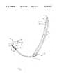
- FIG. 1is a side cross sectional view of a multiple beam antenna system according to an embodiment of this invention, the system including a reflector fed dual orthogonal dielectric lens coupled to a multiple beam port low noise block down converter (LNB).
- LNBlow noise block down converter
- FIG. 2is a front view of the FIG. 1 antenna system.
- FIG. 3is a perspective view of the FIGS. 1-2 antenna system.
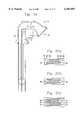
- FIG. 4is an enlarged side cross sectional view of the orthogonal mode junction (OMJ) member of the FIGS. 1-3 embodiment.
- OMJorthogonal mode junction
- FIG. 5is a side cross sectional view of the orthogonal mode junction of the FIGS. 1-4 embodiment.
- FIG. 6is a cross sectional view of the FIGS. 4-5 orthogonal mode junction member taken along section line AA in FIG. 5.
- FIG. 7is a top view of the isolating member of the FIGS. 4-6 orthogonal mode junction member, this member performing orthogonality selection in the junction.
- FIG. 8is a bottom view of a printed circuit board (PCB) from the FIGS. 4-6 orthogonal mode junction member, this PCB transducing horizontal components of the received or transmitted signals into a TEM mode electromagnetic illumination of a parallel plate waveguide connected to the junction; and wherein the base board in FIG. 8 is shown in elevation form and the metal is shown in cross-section.
- PCBprinted circuit board
- FIG. 9is a top view of the FIG. 8 printed circuit board, with metal being shown in cross section and base board shown in an elevation manner.
- FIGS. 10(a) and 10(b)are a schematic illustrating form and dimensions of a lens of the FIGS. 1-9 embodiment of this invention.
- FIG. 11is a cross sectional view of the FIG. 10 lens, along section line A--A.
- FIG. 12is an elevational view of the FIGS. 10-11 lens.
- FIG. 13is a cross sectional view of the FIGS. 10-12 lens, along section line B--B in FIG 10.
- FIG. 14is a side view of a waveguide of the FIG. 1 embodiment of this invention, the waveguide in this figure being shown in "flattened out” form for purposes of illustration (each of the waveguides are not “flat” but are instead curved as shown in FIG. 1, in operative embodiments of this invention).
- FIG. 15is a top view of the FIG. 14 waveguide, including a lens therein.
- FIG. 16is a bottom view of the RF PCB section of the three port low noise block converter (LNB) of the FIG. 1 embodiment of this invention.
- LNBlow noise block converter
- FIG. 17is a top view of the RF PCB section of FIG. 16.
- FIG. 18is a top view of the local oscillator, filter, and down converter PCB within the housing of the LNB in the FIG. 1 embodiment.
- FIGS. 19-22are schematic diagrams illustrating different scenarios of the lenses being manipulated by the output block in order to view particular satellites.
- FIG. 23is a partial cutaway perspective view illustrating the OMJ and the pair of corresponding waveguides and lenses according to an embodiment of this invent ion which may be used in conjunction with the reflector of the FIG. 1 embodiment.
- FIG. 24is a side cross sectional view of the OMJ and waveguides of FIG. 23.
- FIGS. 25(a)-(c)are side cross sectional views of different lenses matching techniques which may be used in any embodiment of this invention.
- FIG. 26is a combination side cross sectional view and schematic of the OMJ and waveguides of FIGS. 23-24.
- FIG. 27is a perspective view of the reflector and OMJ which may be used in any embodiment of this invention.
- FIG. 28is a side plan view of the FIG. 1 system.
- FIG. 1is a side cross sectional view of a multiple beam antenna system according to an embodiment of this invention, the system including a reflector fed dual orthogonal dielectric lens coupled to a multiple beam port low noise block down converter (LNB).
- LNBlow noise block down converter
- the antenna systemcan receive linear components of circularly polarized signals from satellites, break them down and process them as different linear signals, and recreate them to enable a viewer to utilize the received circularly polarized signals.
- the systemis adapted to receive signals in about the 10.70-12.75 GHz range in this and certain other embodiments.
- the multiple beam antenna system of this embodimenttakes advantage of a unique dielectric lens design, including a pair of dielectric lenses 3a and 3b to produce a high gain scanning system with few or no phase controls. Electromagnetic lenses 3a and 3b (described below) are provided in combination with a switching network so as to allow the selection of a single beam or group of beams as required for specific applications.
- the antenna systemreceives (or transmits) signals from multiple satellites simultaneously, these different satellites coexisting.
- the multiples signals received from the multiple satellitesrespectively, split up as a function of orthogonal componentry and follow different waveguides for processing.
- vertically polarized signalsmay be divided out and travel down one waveguide while horizontally polarized signals are divided out and travel down another waveguide.
- a usermay tap into different signals from different satellites, e.g. horizontally polarized signals, vertically polarized signals, or circularly polarized signals.
- a plurality of different satellitesmay be accessed simultaneously enabling a user to utilize multiple signals at the same time.
- a unique featureis the combination of at least partially cylindrical parabolic reflective member 1 with, or operatively associated with, dielectric lenses 3a and 3b.
- the combination of a beam forming network with a phase array illumination of a cylindrical parabolic dishallows the antenna system to simultaneously view many satellites (e.g. up to about seven but not limited to that number) of any polarity along their geostationary orbits.
- the dual lensesfeed the reflective surface 1 of the dish, or vice versa.
- This designallows lenses 3a, 3b to simultaneously see or access more than one satellite signal, and allows the system to scale system or antenna gain and G/T to performance requirements of the user.
- the dish or reflector 1provides efficient pr cheap variable gain (i.e. scaling to accommodate various satellite E.R.I.P. and bandwidth requirements), while the lenses provide the beamforming phase capability.
- the overall systemmay weight from only about 12-15 pounds.
- the multiple beam antenna systems of the different embodimentsmay be used in association with, for example, DBS and TVRO applications.
- an antenna system of relatively high directivityis provided and designed for a limited field of view.
- the system when used in at least DBS applicationsprovides sufficient G/T to adequately demodulate digital or analog television downlink signals from high and/or medium powered Ku band DBS and FSS satellites in geostationary orbit. Other frequency bands may also be transmitted/received.
- the field of viewmay be about 32 degrees in certain embodiments, but may be greater or less in certain other embodiments.
- G/Tthis is the figure of merit of an earth station receiving system and is expressed in dB/K.
- G/TG dBi -10 log T, where G is the gain of the antenna at a specified frequency and T is the receiving system effective noise temperature in degrees Kelvin.
- the antenna systemincludes reflector member 1.
- Reflector 1has a cylindrical parabolic or any other suitable shape, wherein in certain preferred embodiments the reflector has a parabolic shape in the vertical plane and a flat or planar shape in the z-axis. Thus, reflector 1 is not parabolic in both directions, but only one, in certain embodiments of this invention. Because reflector 1 is parabolic in the vertical plane as shown, the system has a long feed assembly along a focal line due to the non-parabolic design in the z-axis.
- reflector 1may be made of structural foam including a reflective metallic coating thereon. According to alternative embodiments of this invention, reflector 1 may be formed as a reflective surface of the waveguide 11.
- reflector 1in combination with dielectric lenses 3a and 3b allows the antenna system of certain embodiments of this invention to receive signals from satellites emitting either horizontally polarized signals or vertically polarized signals as will be discussed below.
- Horizontally and vertically polarized signalsare orthogonal to one another as is known in the art.
- this inventionin alternative embodiments may enable the user to receive signals from satellites emitting either left or right handed circularly polarized signals, or linearly polarized, as will be appreciated, as left and right handed circularly polarized signals are also orthogonal to one another.
- the antenna systemalso includes first and second waveguides 10 and 11 which are collectively numbered 2. These two waveguides are aligned substantially parallel to one another, and each includes two parallel conductive surfaces spaced apart from one another (e.g. by about 3/8"). Waveguides 10 and 11 provide the radial TEM wave guide mode from corresponding lenses 3a and 3b, as they are both TEM mode radial guides. Each waveguide 10 and 11 includes two sections, one section located between OMJ 4 and the corresponding lens 3a, 3b, and another section disposed between the corresponding lens and LNB 5. Each waveguide may be made of any suitable material (e.g. stainless steel) and have, in certain embodiments, a conductive reflective aluminum or copper metal coating (i.e. low loss surface).
- a conductive reflective aluminum or copper metal coatingi.e. low loss surface
- Waveguides 11 and 10allow microwaves from lenses 3a and 3b to focus on different output portions of LNB 5 corresponding to selectable different satellite locations. Two waveguides are needed because one is used to carry or convey each of the two orthogonal polarities, i.e. guide 10 carries one polarity and guide 11 the other polarity.
- Dielectric lenses 3a, 3bare identical to one another in certain embodiments of this invention. Lenses 3a and 3b are fed orthogonally, as one lens 3a facilitates one polarity (e.g. horizontal) while the other lens 3b facilitates an orthogonal polarity (e.g. vertical).
- each lens 3a, 3bmay be made of crystalline polystyrene or alternatively of polyethylene.
- Mount 6supports parallel waveguides 10, 11, as well as lenses 3a, 3b, reflector 1, and junction 4.
- Antenna mount assemblyenables elevational adjustment, azimuthal adjustment, and rotational adjustment of the reflector 1 and feed 21 about the Clark belt.
- Unique orthogonal mode junction 4having feed area 21, receives linear signals from reflector 1, and separates the horizontally polarized signals from the vertically polarized signals, and places or directs them in corresponding separate parallel plate TEM waveguides 10 and 11 in order to illuminate dielectric lenses 3a and 3b.
- satellite signalsfrom a plurality of different satellites, are received by reflector 1 and are reflected into feed 21 of orthogonal mode junction (OMJ) 4 in the form of microwave signals.
- OMJorthogonal mode junction
- Junction 4divides out vertically polarized microwave signals from horizontally polarized microwave signals, and forwards one polarity signal into waveguide 10 and the other polarity signal into waveguide 11.
- one lens 3ais illuminated by the vertical polarization sense and the other lens 3b is illuminated by the horizontal polarization sense.
- An important feature of OMJ 4is that the feedhorn has the ability to accommodate the focal line of cylindrical parabolic reflector 1 and is also able to feed first and second parallel plate TEM-mode waveguides 10, 11, and first and second dielectric lenses 3a and 3b.
- the parallel plate orthogonal mode junction 4 in conjunction with lenses 3a, 3b and the parabolic reflectorprovide the advantages discussed herein.
- LNB 5includes printed circuit boards (PCBs) [shown in FIGS. 16-18] positioned within a housing. LNB 5 is responsible from selecting the specific satellite(s) of interest to the user and configuring the polarities of linear (horizontal and vertical) and circular (right and left hand of choice).
- PCBsprinted circuit boards
- OMJ 4may be made of extruded aluminum, or any other suitable material. Also, impedance matching steps 27 are provided withing the interior of OMJ 4 for impedance matching purposes (i.e. waveguide transformers).
- FIG. 2is a front view of the FIG. 1 antenna system. As shown in FIG. 2, feed 21 of OMJ 4 is elongated in design so as to correspond to a focal line of the reflector which is substantially parallel thereto.
- FIG. 3is a perspective view of the FIG. 1-2 system. Also illustrated in FIG. 3 are endcaps 23 located along the elongated and curved edges of the waveguides.
- FIG. 4is an enlarged side cross sectional view of the orthogonal mode junction (OMJ) member 4 of the FIG. 1-3 embodiment.
- Elongated rods 8, provided in the OMJmay be from about 0.040 to 0.060 inches in diameter (preferably in this embodiment about 0.050 inches in diameter).
- Isolating rods 8are configured within the housing of OMJ 4 so as to isolate the horizontally polarized component of the received (or transmitted) signal that comes into feed 21 from waveguide 10 to waveguide 11.
- isolating board 12 in OMJ 4isolates the vertical component of the received (or transmitted) signal from waveguide 11 to waveguide 10.
- Isolator 12in certain embodiments may be fabricated of 0.0050 (5 mil) inch thick beryllium copper (or plane copper) in order to perform its isolation function.
- FIG. 7is a top view of isolator 12, illustrating the grid assembly responsible for sorting out the orthogonal signals with rods 8.
- rods 8represent the isolating means according to one embodiment of this invention.
- isolating structuremay instead be utilized.
- any suitable structuremay be provided within the illustrated housing of the OMJ for dividing out or isolating the signals of different polarity. Rectangular members, triangular members, annular members, or structure integrally formed with the OMJ housing could instead be used to isolate the signals of different polarity and cause them to proceed toward the different waveguides 10, 11.
- Transducer board 9shown in FIG. 9 as part of OMJ 4, may be a printed circuit board (PCB) fabricated on 0.020 inch thick Teflon fiberglass in certain embodiments.
- PCB 9printed circuit board
- Metal transducers on PCB 9transduce the horizontal component of the received (or transmitted) signal into a TEM mode electromagnetic illumination of parallel plate waveguide 11.
- FIG. 8is a bottom view of transducer board 9 while FIG. 9 is a top view of board 9, with the metallic transducers being shown in cross section.
- OMJ 4further includes radome 7 which has traditional radome characteristics such as protection, in order to accommodate the feed assembly.
- FIGS. 5 and 6further illustrate OMJ 4, with FIG. 6 being a sectional view along section line AA.
- each of components 8, 9, and 12are substantially parallel to one another, and are substantially elongated in design.
- Each of elements 8, 9, and 12is substantially as long as feed 21 of the OMJ.
- FIGS. 10-13illustrate one of dielectric lenses 3a or 3b according to an embodiment of this invention.
- both optical lensesare identical, but may be different in other alternative embodiments.
- One lensis provided for each orthogonal mode, e.g. one for vertical signals and one for horizontal signals.
- the lenses according to this inventioncan receive/transmit linear or circularly polarized signals simultaneously.
- FIGS. 14-15illustrate sectorial feedhorns 13 within one of waveguides 10, 11. It is noted that while FIG. 14 illustrates the waveguide as being "flat” for purposes of simplicity, it really is not flat in practice [note the curved banana-shaped configuration of each waveguide 10, 11 in FIG. 1].
- Feedhorns 13are positioned within the waveguides so as to accommodate the orbital locations of the satellites of interest within the geostationary Clark belt. These focused horns 13 receive the focused signals from the corresponding dielectric lens 3a, 3b of the polarity of the corresponding lens.
- the configurations, quantity or number, and position of feedhorns 13correspond to the number of satellites to be accessed or used.
- the outputs 31 of the feedhornsare coupled to the LNB circuit boards shown in FIGS. 16-18, through rectangular waveguides 33 of the WR-75 type.
- Lines 39illustrate the scanning angle, provided by each feedhorn, of the different satellites (3 in this embodiment) to be accessed or used.
- the positions of the feedhornsdictate which satellites are to be used, it is noted that there is a 15 degree difference in the location of the satellite corresponding to the uppermost feedhorn 33 and the middle feedhorn 33, while there is only a 7.5 degree difference in the position of the satellite corresponding to the middle feedhorn and the lowermost feedhorn 33.
- sectorial feedhorns 33accommodate the satellites of interest.
- feedhorns 13 as shown in FIGS. 14-15are sandwiched between a pair of upper and lower plates that of the corresponding waveguide, which are not shown.
- the LNB 5 housingcontains the two circuit boards shown in FIGS. 16-18. These boards perform the following functions: low noise RF amplification, down converts from RF to IF, selects IF frequency and number of IFs, selects satellites of interest as dictated by the user, selects polarity (linear (hor. or vert.) or circular [right-hand CP or left-hand CP]) of interest, switch matrix for multiple outputs or multiple IFs, IF amplification, converts WR-75 to circuit board strip-line waveguide, compensates for polarity skew in various geographic locations, and may be an antenna to set-topbox interface.
- low noise RF amplificationdown converts from RF to IF
- selects IF frequency and number of IFsselects satellites of interest as dictated by the user
- switch matrixfor multiple outputs or multiple IF
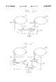
- FIGS. 19-22illustrate how lenses 3a, 3b may be utilized to access different types of signals according to certain embodiments of this invention.
- FIGS. 19-22illustrate how lenses 3a, 3b may be utilized to access different types of signals according to certain embodiments of this invention.
- each lensdeals with a linearly polarized signal (either hor. or vert.), in certain embodiments, circularly polarized signals may also be accessed and utilized.
- the lenses in combination with the multiple beam antenna systems of this inventionallow the systems to select a single beam or a group of beams for reception (i.e. home satellite television viewing). Due to the design of the antenna array and matrix block (including the array of antenna elements of the inventions herein), right-handed circularly polarized satellite signals, left-handed circularly polarized satellite signals, and linearly polarized satellite signals within the scanned field of view may be accessed either individually or in groups. Thus, either a single or a plurality of such satellite signals may be simultaneously received and accessed (e.g. for viewing, etc.).
- FIG. 19illustrates the case where the user manipulates satellite selection matrix to simply pick up the signal from a particular satellite which is transmitting a horizontal signal.
- the path length in lens 3ais adjusted so as to tap into the signal of the desired satellite.
- FIG. 20illustrates the case where a plurality of received outputs from lens 3b are summed or combined in amplitude and phase.
- the signals from two adjacent outputs 65are combined at summer 71 so as to split the beams from the adjacent output ports 65.
- output block 69takes the output from the adjacent ports 65 and sums them at summer 71 thereby "splitting" the beam and receiving the desired satellite signal. It is noted that a small loss of power may occur when signals from adjacent ports 65 are summed in this manner.
- FIG. 21illustrates the case where outputs 65 from both lenses are tapped (in a circular embodiment as described in the '258 patent) so as to result in the receiving of a signal from a satellite having circular (or linear) polarization.
- FIG. 22illustrates the case where it is desired to access a satellite disposed between the beams of adjacent ports 65 wherein the satellite emits a signal having circular (or linear) polarization.
- Adjacent ports 65are accessed in each of lenses and are summed accordingly at summers 75.
- phase shifter 73adjusts the phase of the signal from one lens and the signals from the lenses are combined at summer 71 thereafter outputting a signal from output block 69 indicative of the received circularly polarized signal.
- the above-discussed multiple beam antenna systemcan receive singularly or simultaneously any polarity (circular or linear) from a single or multiple number of satellites, from a single or multiple number of beams, knowing that co-located satellites utilize frequency and/or polarization diversity.
- microwave dielectric lenses 3a and 3b for multibeam or scanning applicationsmay have a bifocal design used in combination with Abbe Sine design methodology. This increases the scanning angle of the lens.
- FIGS. 23, 24, 25(a) and 26illustrate lenses 3a and 3b having a bifocal design with a "step" offset 91 on the edges of the lenses closest to OMJ 4 and another step offset 92 on the opposite edge of the lenses farthest from the OMJ.
- a collimating lenswas designed to be coma free for a limited scan by imposing the known Abbe Sine condition.
- a plano-convex lenswith a dielectric constant from about 2.4 to 2.7 (preferably about 2.55), a coma free beam over an angular coverage of plus/minus eight beam widths, with side lobe performance lower than about -18 dB, was achieved.
- FIGS. 25(a)-(c)illustrate bifocal lenses 3a, 3b according to different embodiments of this invention, located within a parallel plane of the surrounding TEM waveguide.
- the lens 3a (or 3b)includes steps 91 and 92 on opposite edges thereof.
- Each step 91, 92includes a first vertical portion 93 which is oriented approximately perpendicular to the adjacent waveguide surface, a second horizontal surface 94 which is approximately parallel to each of the opposing waveguide surfaces, and a third vertical portion 95 which is approximately perpendicular to portion 94 and to the adjacent waveguide surface.
- the planar portion of the lens whose outer periphery is defined by portions 93has a larger volume and larger surface area adjacent the immediately adjacent waveguide surface than the planar portion of the lens whose periphery is defined by portions 95.
- the FIG. 25(a) lensincludes two planar portions which are either integrally formed with C) 30 one another, or which may be laminated to one another in some embodiments.
- FIG. 25(b) lens 3a, 3bmay be used in other embodiments of this invention.
- This lensincludes a slot 96 defined in the opposing edges of the lens for matching purposes.
- slots of other shapesmay instead be used, such as rectangular, oval, and the like.
- the FIG. 25(c) lens 3a, 3bmay be used in other embodiments of this invention, and includes a plurality of approximately parallel slots defined in the opposing edges of the lens for matching purposes. For example, three slots 97 are shown in each of the opposing edges in FIG. 25(c), although from two through twenty slots may be provided in each edge in different embodiments of this invention.
- the FIG. 25(a) lenshas been found to be easier to manufacture, have lower tolerances, and a higher level of ruggedness and is thus preferred in certain embodiments of this invention for use in volume production.
- OMJ 4 of FIGS. 23, 24, and 26the OMJ of this embodiment is used in conjunction with the illustrated parallel plate TEM radial waveguides.
- the OMJ designenables the use of a single feedhorn which performs as a linear array, with element spacing infinitesimally small, that may be aligned to a focal line of the cylindrical parabola reflector 1.
- the long or elongated feed assembly of the reflector along the focal lineallows OMJ 4 to have an elongated, approximately horizontally aligned, feed 21 as shown in FIGS. 2 and 27.
- OMJ 4in turn delivers signals to the two parallel plate dielectric lenses 3a, 3b in a way that both are electrically orthogonal to one another.
- junctions for waveguidesare single circular or rectangular (square) wave guides with a multiplicity of them used to feed a parallel plate guide.
- the instant OMJis an improvement over traditional techniques which are more complicated and expensive to manufacture.
- conventional junctionswould have to be configured as a multiplicity of elements and their spacing would cause grating lobes and the individual feed patterns would dictate scanning loss for off axis performance.
- the multiple different signals received from the multiple satellites by the illustrated antenna systemrespectively split up as a function of their different orthogonal components (e.g. horizontal and vertical), with the different orthogonal components following different waveguides 10, 11 for processing.
- vertically polarized signalsmay be divided out and caused to travel down one waveguide while horizontally polarized signals are divided out and caused to travel down the other waveguide.
- a usermay tap into different signals from different satellites, e.g. horizontally polarized signals, vertically polarized signals, or circularly polarized signals.
- a plurality of different satellitesmay be accessed simultaneously enabling a user to utilize multiple signals at the same time. Additionally, this invention may enable the user to receive signals from satellites emitting either left or right handed circularly polarized signals, as these signals are also orthogonal to one another.
Landscapes
- Physics & Mathematics (AREA)
- Electromagnetism (AREA)
- Aerials With Secondary Devices (AREA)
- Waveguide Aerials (AREA)
Abstract
Description
Claims (7)
Priority Applications (6)
| Application Number | Priority Date | Filing Date | Title |
|---|---|---|---|
| US09/110,687US6107897A (en) | 1998-01-08 | 1998-07-07 | Orthogonal mode junction (OMJ) for use in antenna system |
| CA002254139ACA2254139A1 (en) | 1998-01-08 | 1998-11-13 | Reflector based dielectric lens antenna system |
| EP98121988AEP0929122A3 (en) | 1998-01-08 | 1998-11-19 | Reflector based dielectric lens antenna system |
| PCT/US1999/000078WO1999035710A1 (en) | 1998-01-08 | 1999-01-05 | Reflector based dielectric lens antenna system |
| AU24509/99AAU2450999A (en) | 1998-01-08 | 1999-01-05 | Reflector based dielectric lens antenna system |
| US09/273,466US6160520A (en) | 1998-01-08 | 1999-03-22 | Distributed bifocal abbe-sine for wide-angle multi-beam and scanning antenna system |
Applications Claiming Priority (2)
| Application Number | Priority Date | Filing Date | Title |
|---|---|---|---|
| US09/004,759US6087999A (en) | 1994-09-01 | 1998-01-08 | Reflector based dielectric lens antenna system |
| US09/110,687US6107897A (en) | 1998-01-08 | 1998-07-07 | Orthogonal mode junction (OMJ) for use in antenna system |
Related Parent Applications (1)
| Application Number | Title | Priority Date | Filing Date |
|---|---|---|---|
| US09/004,759Continuation-In-PartUS6087999A (en) | 1994-09-01 | 1998-01-08 | Reflector based dielectric lens antenna system |
Related Child Applications (1)
| Application Number | Title | Priority Date | Filing Date |
|---|---|---|---|
| US09/273,466Continuation-In-PartUS6160520A (en) | 1998-01-08 | 1999-03-22 | Distributed bifocal abbe-sine for wide-angle multi-beam and scanning antenna system |
Publications (1)
| Publication Number | Publication Date |
|---|---|
| US6107897Atrue US6107897A (en) | 2000-08-22 |
Family
ID=46255011
Family Applications (1)
| Application Number | Title | Priority Date | Filing Date |
|---|---|---|---|
| US09/110,687Expired - Fee RelatedUS6107897A (en) | 1998-01-08 | 1998-07-07 | Orthogonal mode junction (OMJ) for use in antenna system |
Country Status (1)
| Country | Link |
|---|---|
| US (1) | US6107897A (en) |
Cited By (161)
| Publication number | Priority date | Publication date | Assignee | Title |
|---|---|---|---|---|
| WO2001080363A1 (en)* | 2000-04-07 | 2001-10-25 | Gilat Satellite Networks | Multi-feed reflector antenna |
| US20030128532A1 (en)* | 2002-01-10 | 2003-07-10 | Junichi Somei | Printed circuit board, radio wave receiving converter, and antenna device |
| US20090273508A1 (en)* | 2008-04-30 | 2009-11-05 | Thomas Binzer | Multi-beam radar sensor |
| EP2127024A1 (en)* | 2007-01-19 | 2009-12-02 | Plasma Antennas Limited | A displaced feed parallel plate antenna |
| US20110043403A1 (en)* | 2008-02-27 | 2011-02-24 | Synview Gmbh | Millimeter wave camera with improved resolution through the use of the sar principle in combination with a focusing optic |
| US8558734B1 (en)* | 2009-07-22 | 2013-10-15 | Gregory Hubert Piesinger | Three dimensional radar antenna method and apparatus |
| US20140022137A1 (en)* | 2012-07-20 | 2014-01-23 | Thales | Antenna and multi-beam antenna system comprising compact feeds and satellite telecommunication system comprising at least one such antenna |
| US20140022138A1 (en)* | 2012-07-20 | 2014-01-23 | Thales | Multibeam Transmitting and Receiving Antenna with Multiple Feeds Per Beam, System of Antennas and Satellite Telecommunication System Containing Such an Antenna |
| US9544006B2 (en) | 2014-11-20 | 2017-01-10 | At&T Intellectual Property I, L.P. | Transmission device with mode division multiplexing and methods for use therewith |
| US9577306B2 (en) | 2014-10-21 | 2017-02-21 | At&T Intellectual Property I, L.P. | Guided-wave transmission device and methods for use therewith |
| US9596001B2 (en) | 2014-10-21 | 2017-03-14 | At&T Intellectual Property I, L.P. | Apparatus for providing communication services and methods thereof |
| US9608740B2 (en) | 2015-07-15 | 2017-03-28 | At&T Intellectual Property I, L.P. | Method and apparatus for launching a wave mode that mitigates interference |
| US9608692B2 (en) | 2015-06-11 | 2017-03-28 | At&T Intellectual Property I, L.P. | Repeater and methods for use therewith |
| US9615269B2 (en) | 2014-10-02 | 2017-04-04 | At&T Intellectual Property I, L.P. | Method and apparatus that provides fault tolerance in a communication network |
| US9628116B2 (en) | 2015-07-14 | 2017-04-18 | At&T Intellectual Property I, L.P. | Apparatus and methods for transmitting wireless signals |
| US9627768B2 (en) | 2014-10-21 | 2017-04-18 | At&T Intellectual Property I, L.P. | Guided-wave transmission device with non-fundamental mode propagation and methods for use therewith |
| US9640850B2 (en) | 2015-06-25 | 2017-05-02 | At&T Intellectual Property I, L.P. | Methods and apparatus for inducing a non-fundamental wave mode on a transmission medium |
| US9653770B2 (en) | 2014-10-21 | 2017-05-16 | At&T Intellectual Property I, L.P. | Guided wave coupler, coupling module and methods for use therewith |
| US9654173B2 (en) | 2014-11-20 | 2017-05-16 | At&T Intellectual Property I, L.P. | Apparatus for powering a communication device and methods thereof |
| US9661505B2 (en) | 2013-11-06 | 2017-05-23 | At&T Intellectual Property I, L.P. | Surface-wave communications and methods thereof |
| US9667317B2 (en) | 2015-06-15 | 2017-05-30 | At&T Intellectual Property I, L.P. | Method and apparatus for providing security using network traffic adjustments |
| US9685992B2 (en) | 2014-10-03 | 2017-06-20 | At&T Intellectual Property I, L.P. | Circuit panel network and methods thereof |
| US9692101B2 (en) | 2014-08-26 | 2017-06-27 | At&T Intellectual Property I, L.P. | Guided wave couplers for coupling electromagnetic waves between a waveguide surface and a surface of a wire |
| US9699785B2 (en) | 2012-12-05 | 2017-07-04 | At&T Intellectual Property I, L.P. | Backhaul link for distributed antenna system |
| US9705561B2 (en) | 2015-04-24 | 2017-07-11 | At&T Intellectual Property I, L.P. | Directional coupling device and methods for use therewith |
| US9705610B2 (en) | 2014-10-21 | 2017-07-11 | At&T Intellectual Property I, L.P. | Transmission device with impairment compensation and methods for use therewith |
| US9712350B2 (en) | 2014-11-20 | 2017-07-18 | At&T Intellectual Property I, L.P. | Transmission device with channel equalization and control and methods for use therewith |
| US9722318B2 (en) | 2015-07-14 | 2017-08-01 | At&T Intellectual Property I, L.P. | Method and apparatus for coupling an antenna to a device |
| US9729197B2 (en) | 2015-10-01 | 2017-08-08 | At&T Intellectual Property I, L.P. | Method and apparatus for communicating network management traffic over a network |
| US9735833B2 (en) | 2015-07-31 | 2017-08-15 | At&T Intellectual Property I, L.P. | Method and apparatus for communications management in a neighborhood network |
| US9742462B2 (en) | 2014-12-04 | 2017-08-22 | At&T Intellectual Property I, L.P. | Transmission medium and communication interfaces and methods for use therewith |
| US9749053B2 (en) | 2015-07-23 | 2017-08-29 | At&T Intellectual Property I, L.P. | Node device, repeater and methods for use therewith |
| US9748626B2 (en) | 2015-05-14 | 2017-08-29 | At&T Intellectual Property I, L.P. | Plurality of cables having different cross-sectional shapes which are bundled together to form a transmission medium |
| US9749013B2 (en) | 2015-03-17 | 2017-08-29 | At&T Intellectual Property I, L.P. | Method and apparatus for reducing attenuation of electromagnetic waves guided by a transmission medium |
| US9762289B2 (en) | 2014-10-14 | 2017-09-12 | At&T Intellectual Property I, L.P. | Method and apparatus for transmitting or receiving signals in a transportation system |
| US9769128B2 (en) | 2015-09-28 | 2017-09-19 | At&T Intellectual Property I, L.P. | Method and apparatus for encryption of communications over a network |
| US9769020B2 (en) | 2014-10-21 | 2017-09-19 | At&T Intellectual Property I, L.P. | Method and apparatus for responding to events affecting communications in a communication network |
| US9768833B2 (en) | 2014-09-15 | 2017-09-19 | At&T Intellectual Property I, L.P. | Method and apparatus for sensing a condition in a transmission medium of electromagnetic waves |
| US9780834B2 (en) | 2014-10-21 | 2017-10-03 | At&T Intellectual Property I, L.P. | Method and apparatus for transmitting electromagnetic waves |
| US9787412B2 (en) | 2015-06-25 | 2017-10-10 | At&T Intellectual Property I, L.P. | Methods and apparatus for inducing a fundamental wave mode on a transmission medium |
| US9793955B2 (en) | 2015-04-24 | 2017-10-17 | At&T Intellectual Property I, Lp | Passive electrical coupling device and methods for use therewith |
| US9793954B2 (en) | 2015-04-28 | 2017-10-17 | At&T Intellectual Property I, L.P. | Magnetic coupling device and methods for use therewith |
| US9794003B2 (en) | 2013-12-10 | 2017-10-17 | At&T Intellectual Property I, L.P. | Quasi-optical coupler |
| US9793951B2 (en) | 2015-07-15 | 2017-10-17 | At&T Intellectual Property I, L.P. | Method and apparatus for launching a wave mode that mitigates interference |
| US9800327B2 (en) | 2014-11-20 | 2017-10-24 | At&T Intellectual Property I, L.P. | Apparatus for controlling operations of a communication device and methods thereof |
| US9820146B2 (en) | 2015-06-12 | 2017-11-14 | At&T Intellectual Property I, L.P. | Method and apparatus for authentication and identity management of communicating devices |
| US9838078B2 (en) | 2015-07-31 | 2017-12-05 | At&T Intellectual Property I, L.P. | Method and apparatus for exchanging communication signals |
| US9838896B1 (en) | 2016-12-09 | 2017-12-05 | At&T Intellectual Property I, L.P. | Method and apparatus for assessing network coverage |
| US9836957B2 (en) | 2015-07-14 | 2017-12-05 | At&T Intellectual Property I, L.P. | Method and apparatus for communicating with premises equipment |
| US9847566B2 (en) | 2015-07-14 | 2017-12-19 | At&T Intellectual Property I, L.P. | Method and apparatus for adjusting a field of a signal to mitigate interference |
| US9847850B2 (en) | 2014-10-14 | 2017-12-19 | At&T Intellectual Property I, L.P. | Method and apparatus for adjusting a mode of communication in a communication network |
| US9853342B2 (en) | 2015-07-14 | 2017-12-26 | At&T Intellectual Property I, L.P. | Dielectric transmission medium connector and methods for use therewith |
| US9860075B1 (en) | 2016-08-26 | 2018-01-02 | At&T Intellectual Property I, L.P. | Method and communication node for broadband distribution |
| US9866309B2 (en) | 2015-06-03 | 2018-01-09 | At&T Intellectual Property I, Lp | Host node device and methods for use therewith |
| US9865911B2 (en) | 2015-06-25 | 2018-01-09 | At&T Intellectual Property I, L.P. | Waveguide system for slot radiating first electromagnetic waves that are combined into a non-fundamental wave mode second electromagnetic wave on a transmission medium |
| US9866276B2 (en) | 2014-10-10 | 2018-01-09 | At&T Intellectual Property I, L.P. | Method and apparatus for arranging communication sessions in a communication system |
| US9871283B2 (en) | 2015-07-23 | 2018-01-16 | At&T Intellectual Property I, Lp | Transmission medium having a dielectric core comprised of plural members connected by a ball and socket configuration |
| US9871282B2 (en) | 2015-05-14 | 2018-01-16 | At&T Intellectual Property I, L.P. | At least one transmission medium having a dielectric surface that is covered at least in part by a second dielectric |
| US9876605B1 (en) | 2016-10-21 | 2018-01-23 | At&T Intellectual Property I, L.P. | Launcher and coupling system to support desired guided wave mode |
| US9876570B2 (en) | 2015-02-20 | 2018-01-23 | At&T Intellectual Property I, Lp | Guided-wave transmission device with non-fundamental mode propagation and methods for use therewith |
| US9876264B2 (en) | 2015-10-02 | 2018-01-23 | At&T Intellectual Property I, Lp | Communication system, guided wave switch and methods for use therewith |
| US9882277B2 (en) | 2015-10-02 | 2018-01-30 | At&T Intellectual Property I, Lp | Communication device and antenna assembly with actuated gimbal mount |
| US9882257B2 (en) | 2015-07-14 | 2018-01-30 | At&T Intellectual Property I, L.P. | Method and apparatus for launching a wave mode that mitigates interference |
| US9887447B2 (en) | 2015-05-14 | 2018-02-06 | At&T Intellectual Property I, L.P. | Transmission medium having multiple cores and methods for use therewith |
| US9893795B1 (en) | 2016-12-07 | 2018-02-13 | At&T Intellectual Property I, Lp | Method and repeater for broadband distribution |
| US9906269B2 (en) | 2014-09-17 | 2018-02-27 | At&T Intellectual Property I, L.P. | Monitoring and mitigating conditions in a communication network |
| US9904535B2 (en) | 2015-09-14 | 2018-02-27 | At&T Intellectual Property I, L.P. | Method and apparatus for distributing software |
| US9911020B1 (en) | 2016-12-08 | 2018-03-06 | At&T Intellectual Property I, L.P. | Method and apparatus for tracking via a radio frequency identification device |
| US9912027B2 (en) | 2015-07-23 | 2018-03-06 | At&T Intellectual Property I, L.P. | Method and apparatus for exchanging communication signals |
| US9912381B2 (en) | 2015-06-03 | 2018-03-06 | At&T Intellectual Property I, Lp | Network termination and methods for use therewith |
| US9913139B2 (en) | 2015-06-09 | 2018-03-06 | At&T Intellectual Property I, L.P. | Signal fingerprinting for authentication of communicating devices |
| US9912419B1 (en) | 2016-08-24 | 2018-03-06 | At&T Intellectual Property I, L.P. | Method and apparatus for managing a fault in a distributed antenna system |
| US9917341B2 (en) | 2015-05-27 | 2018-03-13 | At&T Intellectual Property I, L.P. | Apparatus and method for launching electromagnetic waves and for modifying radial dimensions of the propagating electromagnetic waves |
| US9930668B2 (en) | 2013-05-31 | 2018-03-27 | At&T Intellectual Property I, L.P. | Remote distributed antenna system |
| US9927517B1 (en) | 2016-12-06 | 2018-03-27 | At&T Intellectual Property I, L.P. | Apparatus and methods for sensing rainfall |
| US9948333B2 (en) | 2015-07-23 | 2018-04-17 | At&T Intellectual Property I, L.P. | Method and apparatus for wireless communications to mitigate interference |
| US9948354B2 (en) | 2015-04-28 | 2018-04-17 | At&T Intellectual Property I, L.P. | Magnetic coupling device with reflective plate and methods for use therewith |
| US9954287B2 (en) | 2014-11-20 | 2018-04-24 | At&T Intellectual Property I, L.P. | Apparatus for converting wireless signals and electromagnetic waves and methods thereof |
| US9967173B2 (en) | 2015-07-31 | 2018-05-08 | At&T Intellectual Property I, L.P. | Method and apparatus for authentication and identity management of communicating devices |
| US9973940B1 (en) | 2017-02-27 | 2018-05-15 | At&T Intellectual Property I, L.P. | Apparatus and methods for dynamic impedance matching of a guided wave launcher |
| US9991580B2 (en) | 2016-10-21 | 2018-06-05 | At&T Intellectual Property I, L.P. | Launcher and coupling system for guided wave mode cancellation |
| US9998870B1 (en) | 2016-12-08 | 2018-06-12 | At&T Intellectual Property I, L.P. | Method and apparatus for proximity sensing |
| US9999038B2 (en) | 2013-05-31 | 2018-06-12 | At&T Intellectual Property I, L.P. | Remote distributed antenna system |
| US9997819B2 (en) | 2015-06-09 | 2018-06-12 | At&T Intellectual Property I, L.P. | Transmission medium and method for facilitating propagation of electromagnetic waves via a core |
| US10009067B2 (en) | 2014-12-04 | 2018-06-26 | At&T Intellectual Property I, L.P. | Method and apparatus for configuring a communication interface |
| US10009901B2 (en) | 2015-09-16 | 2018-06-26 | At&T Intellectual Property I, L.P. | Method, apparatus, and computer-readable storage medium for managing utilization of wireless resources between base stations |
| US10009065B2 (en) | 2012-12-05 | 2018-06-26 | At&T Intellectual Property I, L.P. | Backhaul link for distributed antenna system |
| US10009063B2 (en) | 2015-09-16 | 2018-06-26 | At&T Intellectual Property I, L.P. | Method and apparatus for use with a radio distributed antenna system having an out-of-band reference signal |
| US10020844B2 (en) | 2016-12-06 | 2018-07-10 | T&T Intellectual Property I, L.P. | Method and apparatus for broadcast communication via guided waves |
| US10020587B2 (en) | 2015-07-31 | 2018-07-10 | At&T Intellectual Property I, L.P. | Radial antenna and methods for use therewith |
| US10027397B2 (en) | 2016-12-07 | 2018-07-17 | At&T Intellectual Property I, L.P. | Distributed antenna system and methods for use therewith |
| US10033107B2 (en) | 2015-07-14 | 2018-07-24 | At&T Intellectual Property I, L.P. | Method and apparatus for coupling an antenna to a device |
| US10033108B2 (en) | 2015-07-14 | 2018-07-24 | At&T Intellectual Property I, L.P. | Apparatus and methods for generating an electromagnetic wave having a wave mode that mitigates interference |
| US10044409B2 (en) | 2015-07-14 | 2018-08-07 | At&T Intellectual Property I, L.P. | Transmission medium and methods for use therewith |
| US10069535B2 (en) | 2016-12-08 | 2018-09-04 | At&T Intellectual Property I, L.P. | Apparatus and methods for launching electromagnetic waves having a certain electric field structure |
| US10079661B2 (en) | 2015-09-16 | 2018-09-18 | At&T Intellectual Property I, L.P. | Method and apparatus for use with a radio distributed antenna system having a clock reference |
| US10090606B2 (en) | 2015-07-15 | 2018-10-02 | At&T Intellectual Property I, L.P. | Antenna system with dielectric array and methods for use therewith |
| US10090594B2 (en) | 2016-11-23 | 2018-10-02 | At&T Intellectual Property I, L.P. | Antenna system having structural configurations for assembly |
| US10103801B2 (en) | 2015-06-03 | 2018-10-16 | At&T Intellectual Property I, L.P. | Host node device and methods for use therewith |
| US10103422B2 (en) | 2016-12-08 | 2018-10-16 | At&T Intellectual Property I, L.P. | Method and apparatus for mounting network devices |
| US10135145B2 (en) | 2016-12-06 | 2018-11-20 | At&T Intellectual Property I, L.P. | Apparatus and methods for generating an electromagnetic wave along a transmission medium |
| US10135147B2 (en) | 2016-10-18 | 2018-11-20 | At&T Intellectual Property I, L.P. | Apparatus and methods for launching guided waves via an antenna |
| US10136434B2 (en) | 2015-09-16 | 2018-11-20 | At&T Intellectual Property I, L.P. | Method and apparatus for use with a radio distributed antenna system having an ultra-wideband control channel |
| US10135146B2 (en) | 2016-10-18 | 2018-11-20 | At&T Intellectual Property I, L.P. | Apparatus and methods for launching guided waves via circuits |
| US10142086B2 (en) | 2015-06-11 | 2018-11-27 | At&T Intellectual Property I, L.P. | Repeater and methods for use therewith |
| US10139820B2 (en) | 2016-12-07 | 2018-11-27 | At&T Intellectual Property I, L.P. | Method and apparatus for deploying equipment of a communication system |
| US10144036B2 (en) | 2015-01-30 | 2018-12-04 | At&T Intellectual Property I, L.P. | Method and apparatus for mitigating interference affecting a propagation of electromagnetic waves guided by a transmission medium |
| US10148016B2 (en) | 2015-07-14 | 2018-12-04 | At&T Intellectual Property I, L.P. | Apparatus and methods for communicating utilizing an antenna array |
| US10170840B2 (en) | 2015-07-14 | 2019-01-01 | At&T Intellectual Property I, L.P. | Apparatus and methods for sending or receiving electromagnetic signals |
| US10168695B2 (en) | 2016-12-07 | 2019-01-01 | At&T Intellectual Property I, L.P. | Method and apparatus for controlling an unmanned aircraft |
| US10178445B2 (en) | 2016-11-23 | 2019-01-08 | At&T Intellectual Property I, L.P. | Methods, devices, and systems for load balancing between a plurality of waveguides |
| US10205655B2 (en) | 2015-07-14 | 2019-02-12 | At&T Intellectual Property I, L.P. | Apparatus and methods for communicating utilizing an antenna array and multiple communication paths |
| US10225025B2 (en) | 2016-11-03 | 2019-03-05 | At&T Intellectual Property I, L.P. | Method and apparatus for detecting a fault in a communication system |
| US10224634B2 (en) | 2016-11-03 | 2019-03-05 | At&T Intellectual Property I, L.P. | Methods and apparatus for adjusting an operational characteristic of an antenna |
| US10243270B2 (en) | 2016-12-07 | 2019-03-26 | At&T Intellectual Property I, L.P. | Beam adaptive multi-feed dielectric antenna system and methods for use therewith |
| US10243784B2 (en) | 2014-11-20 | 2019-03-26 | At&T Intellectual Property I, L.P. | System for generating topology information and methods thereof |
| US10264586B2 (en) | 2016-12-09 | 2019-04-16 | At&T Mobility Ii Llc | Cloud-based packet controller and methods for use therewith |
| US10291311B2 (en) | 2016-09-09 | 2019-05-14 | At&T Intellectual Property I, L.P. | Method and apparatus for mitigating a fault in a distributed antenna system |
| US10291334B2 (en) | 2016-11-03 | 2019-05-14 | At&T Intellectual Property I, L.P. | System for detecting a fault in a communication system |
| US10298293B2 (en) | 2017-03-13 | 2019-05-21 | At&T Intellectual Property I, L.P. | Apparatus of communication utilizing wireless network devices |
| US10305190B2 (en) | 2016-12-01 | 2019-05-28 | At&T Intellectual Property I, L.P. | Reflecting dielectric antenna system and methods for use therewith |
| US10312567B2 (en) | 2016-10-26 | 2019-06-04 | At&T Intellectual Property I, L.P. | Launcher with planar strip antenna and methods for use therewith |
| US10320586B2 (en) | 2015-07-14 | 2019-06-11 | At&T Intellectual Property I, L.P. | Apparatus and methods for generating non-interfering electromagnetic waves on an insulated transmission medium |
| US10326494B2 (en) | 2016-12-06 | 2019-06-18 | At&T Intellectual Property I, L.P. | Apparatus for measurement de-embedding and methods for use therewith |
| US10326689B2 (en) | 2016-12-08 | 2019-06-18 | At&T Intellectual Property I, L.P. | Method and system for providing alternative communication paths |
| US10340600B2 (en) | 2016-10-18 | 2019-07-02 | At&T Intellectual Property I, L.P. | Apparatus and methods for launching guided waves via plural waveguide systems |
| US10340573B2 (en) | 2016-10-26 | 2019-07-02 | At&T Intellectual Property I, L.P. | Launcher with cylindrical coupling device and methods for use therewith |
| US10341142B2 (en) | 2015-07-14 | 2019-07-02 | At&T Intellectual Property I, L.P. | Apparatus and methods for generating non-interfering electromagnetic waves on an uninsulated conductor |
| US10340983B2 (en) | 2016-12-09 | 2019-07-02 | At&T Intellectual Property I, L.P. | Method and apparatus for surveying remote sites via guided wave communications |
| US10340601B2 (en) | 2016-11-23 | 2019-07-02 | At&T Intellectual Property I, L.P. | Multi-antenna system and methods for use therewith |
| US10340603B2 (en) | 2016-11-23 | 2019-07-02 | At&T Intellectual Property I, L.P. | Antenna system having shielded structural configurations for assembly |
| US10355367B2 (en) | 2015-10-16 | 2019-07-16 | At&T Intellectual Property I, L.P. | Antenna structure for exchanging wireless signals |
| US10361489B2 (en) | 2016-12-01 | 2019-07-23 | At&T Intellectual Property I, L.P. | Dielectric dish antenna system and methods for use therewith |
| US10359749B2 (en) | 2016-12-07 | 2019-07-23 | At&T Intellectual Property I, L.P. | Method and apparatus for utilities management via guided wave communication |
| US10374316B2 (en) | 2016-10-21 | 2019-08-06 | At&T Intellectual Property I, L.P. | System and dielectric antenna with non-uniform dielectric |
| US10382976B2 (en) | 2016-12-06 | 2019-08-13 | At&T Intellectual Property I, L.P. | Method and apparatus for managing wireless communications based on communication paths and network device positions |
| US10389029B2 (en) | 2016-12-07 | 2019-08-20 | At&T Intellectual Property I, L.P. | Multi-feed dielectric antenna system with core selection and methods for use therewith |
| US10389037B2 (en) | 2016-12-08 | 2019-08-20 | At&T Intellectual Property I, L.P. | Apparatus and methods for selecting sections of an antenna array and use therewith |
| US10411356B2 (en) | 2016-12-08 | 2019-09-10 | At&T Intellectual Property I, L.P. | Apparatus and methods for selectively targeting communication devices with an antenna array |
| US10439675B2 (en) | 2016-12-06 | 2019-10-08 | At&T Intellectual Property I, L.P. | Method and apparatus for repeating guided wave communication signals |
| US10446936B2 (en) | 2016-12-07 | 2019-10-15 | At&T Intellectual Property I, L.P. | Multi-feed dielectric antenna system and methods for use therewith |
| US10498044B2 (en) | 2016-11-03 | 2019-12-03 | At&T Intellectual Property I, L.P. | Apparatus for configuring a surface of an antenna |
| US10530505B2 (en) | 2016-12-08 | 2020-01-07 | At&T Intellectual Property I, L.P. | Apparatus and methods for launching electromagnetic waves along a transmission medium |
| US10535928B2 (en) | 2016-11-23 | 2020-01-14 | At&T Intellectual Property I, L.P. | Antenna system and methods for use therewith |
| US10547348B2 (en) | 2016-12-07 | 2020-01-28 | At&T Intellectual Property I, L.P. | Method and apparatus for switching transmission mediums in a communication system |
| US10601494B2 (en) | 2016-12-08 | 2020-03-24 | At&T Intellectual Property I, L.P. | Dual-band communication device and method for use therewith |
| US10637149B2 (en) | 2016-12-06 | 2020-04-28 | At&T Intellectual Property I, L.P. | Injection molded dielectric antenna and methods for use therewith |
| US10650940B2 (en) | 2015-05-15 | 2020-05-12 | At&T Intellectual Property I, L.P. | Transmission medium having a conductive material and methods for use therewith |
| US10665942B2 (en) | 2015-10-16 | 2020-05-26 | At&T Intellectual Property I, L.P. | Method and apparatus for adjusting wireless communications |
| US10694379B2 (en) | 2016-12-06 | 2020-06-23 | At&T Intellectual Property I, L.P. | Waveguide system with device-based authentication and methods for use therewith |
| US10727599B2 (en) | 2016-12-06 | 2020-07-28 | At&T Intellectual Property I, L.P. | Launcher with slot antenna and methods for use therewith |
| US10755542B2 (en) | 2016-12-06 | 2020-08-25 | At&T Intellectual Property I, L.P. | Method and apparatus for surveillance via guided wave communication |
| US10777873B2 (en) | 2016-12-08 | 2020-09-15 | At&T Intellectual Property I, L.P. | Method and apparatus for mounting network devices |
| US10784670B2 (en) | 2015-07-23 | 2020-09-22 | At&T Intellectual Property I, L.P. | Antenna support for aligning an antenna |
| US10797781B2 (en) | 2015-06-03 | 2020-10-06 | At&T Intellectual Property I, L.P. | Client node device and methods for use therewith |
| US10811767B2 (en) | 2016-10-21 | 2020-10-20 | At&T Intellectual Property I, L.P. | System and dielectric antenna with convex dielectric radome |
| US10819035B2 (en) | 2016-12-06 | 2020-10-27 | At&T Intellectual Property I, L.P. | Launcher with helical antenna and methods for use therewith |
| US10916969B2 (en) | 2016-12-08 | 2021-02-09 | At&T Intellectual Property I, L.P. | Method and apparatus for providing power using an inductive coupling |
| US10938108B2 (en) | 2016-12-08 | 2021-03-02 | At&T Intellectual Property I, L.P. | Frequency selective multi-feed dielectric antenna system and methods for use therewith |
| US11032819B2 (en) | 2016-09-15 | 2021-06-08 | At&T Intellectual Property I, L.P. | Method and apparatus for use with a radio distributed antenna system having a control channel reference signal |
| US11469515B2 (en) | 2020-02-25 | 2022-10-11 | Isotropic Systems Ltd. | Prism for repointing reflector antenna main beam |
Citations (59)
| Publication number | Priority date | Publication date | Assignee | Title |
|---|---|---|---|---|
| US2682610A (en)* | 1951-12-06 | 1954-06-29 | Bell Telephone Labor Inc | Selective mode transducer |
| US2735092A (en)* | 1955-04-04 | 1956-02-14 | Guide space | |
| US2816271A (en)* | 1950-11-22 | 1957-12-10 | Gen Electric | Microwave mode converter |
| US2847672A (en)* | 1956-07-13 | 1958-08-12 | Itt | Antenna arrays |
| US2863148A (en)* | 1954-06-17 | 1958-12-02 | Emi Ltd | Helical antenna enclosed in a dielectric |
| US2934762A (en)* | 1956-11-15 | 1960-04-26 | Sperry Rand Corp | Selective polarization antenna |
| US2953781A (en)* | 1959-11-30 | 1960-09-20 | John R Donnellan | Polarization diversity with flat spiral antennas |
| US2975380A (en)* | 1957-09-30 | 1961-03-14 | Raytheon Co | Waveguide transducer |
| US2977594A (en)* | 1958-08-14 | 1961-03-28 | Arthur E Marston | Spiral doublet antenna |
| US2982959A (en)* | 1960-06-27 | 1961-05-02 | Dietrich V Hanneken | Antenna for both horizontally and vertically polarized waves |
| US3017633A (en)* | 1959-11-30 | 1962-01-16 | Arthur E Marston | Linearly polarized spiral antenna system and feed system therefor |
| US3135960A (en)* | 1961-12-29 | 1964-06-02 | Jr Julius A Kaiser | Spiral mode selector circuit for a twowire archimedean spiral antenna |
| US3170158A (en)* | 1963-05-08 | 1965-02-16 | Rotman Walter | Multiple beam radar antenna system |
| US3267472A (en)* | 1960-07-20 | 1966-08-16 | Litton Systems Inc | Variable aperture antenna system |
| US3369197A (en)* | 1965-01-05 | 1968-02-13 | Bell Telephone Labor Inc | Waveguide mode coupler |
| US3509572A (en)* | 1966-12-08 | 1970-04-28 | Sylvania Electric Prod | Waveguide fed frequency independent antenna |
| US3623118A (en)* | 1969-07-01 | 1971-11-23 | Raytheon Co | Waveguide-fed helical antenna |
| US3718932A (en)* | 1971-06-01 | 1973-02-27 | Us Army | Combined multi-polarization loopstick and whip antenna |
| US3864688A (en)* | 1972-03-24 | 1975-02-04 | Andrew Corp | Cross-polarized parabolic antenna |
| US3931624A (en)* | 1974-03-21 | 1976-01-06 | Tull Aviation Corporation | Antenna array for aircraft guidance system |
| US3932822A (en)* | 1975-01-30 | 1976-01-13 | Edward Salzberg | Broad band orthogonal mode junction |
| US4123759A (en)* | 1977-03-21 | 1978-10-31 | Microwave Associates, Inc. | Phased array antenna |
| JPS56141602A (en)* | 1980-04-07 | 1981-11-05 | Toshiba Corp | Lens antenna equipment |
| US4315266A (en)* | 1980-07-25 | 1982-02-09 | Nasa | Spiral slotted phased antenna array |
| US4366453A (en)* | 1981-01-19 | 1982-12-28 | Harris Corporation | Orthogonal mode transducer having interface plates at the junction of the waveguides |
| US4400703A (en)* | 1980-06-24 | 1983-08-23 | Kokusai Denshin Denwa Kabushiki Kaisha | Spiral array antenna |
| JPS58187003A (en)* | 1982-04-27 | 1983-11-01 | Toshiba Corp | Antenna using R-hR lens |
| US4427984A (en)* | 1981-07-29 | 1984-01-24 | General Electric Company | Phase-variable spiral antenna and steerable arrays thereof |
| US4467294A (en)* | 1981-12-17 | 1984-08-21 | Vitalink Communications Corporation | Waveguide apparatus and method for dual polarized and dual frequency signals |
| US4467329A (en)* | 1981-05-27 | 1984-08-21 | General Electric Company | Loaded waveguide lenses |
| US4494117A (en)* | 1982-07-19 | 1985-01-15 | The United States Of America As Represented By The Secretary Of The Navy | Dual sense, circularly polarized helical antenna |
| US4511868A (en)* | 1982-09-13 | 1985-04-16 | Ball Corporation | Apparatus and method for transfer of r.f. energy through a mechanically rotatable joint |
| US4584588A (en)* | 1982-11-12 | 1986-04-22 | Kabelmetal Electro Gmbh | Antenna with feed horn and polarization feed |
| US4647938A (en)* | 1984-10-29 | 1987-03-03 | Agence Spatiale Europeenne | Double grid reflector antenna |
| US4660050A (en)* | 1983-04-06 | 1987-04-21 | Trw Inc. | Doppler radar velocity measurement horn |
| US4680591A (en)* | 1983-07-01 | 1987-07-14 | Emi Limited | Helical antenna array with resonant cavity and impedance matching means |
| US4785302A (en)* | 1985-10-30 | 1988-11-15 | Capetronic (Bsr) Ltd. | Automatic polarization control system for TVRO receivers |
| US4791428A (en)* | 1987-05-15 | 1988-12-13 | Ray J. Hillenbrand | Microwave receiving antenna array having adjustable null direction |
| US4845507A (en)* | 1987-08-07 | 1989-07-04 | Raytheon Company | Modular multibeam radio frequency array antenna system |
| US4920351A (en)* | 1986-03-24 | 1990-04-24 | Computer Science Inovations, Inc. | Diplexer for orthogonally polarized transmit/receive signalling on common frequency |
| US5041842A (en)* | 1990-04-18 | 1991-08-20 | Blaese Herbert R | Helical base station antenna with support |
| US5053786A (en)* | 1982-01-28 | 1991-10-01 | General Instrument Corporation | Broadband directional antenna |
| US5061943A (en)* | 1988-08-03 | 1991-10-29 | Agence Spatiale Europenne | Planar array antenna, comprising coplanar waveguide printed feed lines cooperating with apertures in a ground plane |
| WO1992007394A1 (en)* | 1990-10-18 | 1992-04-30 | D-Mac International Limited | Satellite antenna |
| US5117240A (en)* | 1988-01-11 | 1992-05-26 | Microbeam Corporation | Multimode dielectric-loaded double-flare antenna |
| US5146234A (en)* | 1989-09-08 | 1992-09-08 | Ball Corporation | Dual polarized spiral antenna |
| US5227807A (en)* | 1989-11-29 | 1993-07-13 | Ael Defense Corp. | Dual polarized ambidextrous multiple deformed aperture spiral antennas |
| EP0553707A1 (en)* | 1992-01-23 | 1993-08-04 | Yokowo Co., Ltd. | Circulary-polarized-wave flat antenna |
| US5243358A (en)* | 1991-07-15 | 1993-09-07 | Ball Corporation | Directional scanning circular phased array antenna |
| US5255004A (en)* | 1991-09-09 | 1993-10-19 | Cubic Defense Systems, Inc. | Linear array dual polarization for roll compensation |
| US5258771A (en)* | 1990-05-14 | 1993-11-02 | General Electric Co. | Interleaved helix arrays |
| WO1994016472A1 (en)* | 1992-12-30 | 1994-07-21 | Thomson Consumer Electronics S.A. | Helical antenna system |
| US5345248A (en)* | 1992-07-22 | 1994-09-06 | Space Systems/Loral, Inc. | Staggered helical array antenna |
| US5359336A (en)* | 1992-03-31 | 1994-10-25 | Sony Corporation | Circularly polarized wave generator and circularly polarized wave receiving antenna |
| EP0682383A1 (en)* | 1994-05-10 | 1995-11-15 | Dassault Electronique | Multi beam antenna for microwave reception from multiple satellites |
| US5495258A (en)* | 1994-09-01 | 1996-02-27 | Nicholas L. Muhlhauser | Multiple beam antenna system for simultaneously receiving multiple satellite signals |
| US5528717A (en)* | 1994-06-10 | 1996-06-18 | The United States Of America As Represented By The Secretary Of The Army | Hybrid dielectric slab beam waveguide |
| US5619173A (en)* | 1991-06-18 | 1997-04-08 | Cambridge Computer Limited | Dual polarization waveguide including means for reflecting and rotating dual polarized signals |
| US5652597A (en)* | 1993-08-23 | 1997-07-29 | Alcatel Espace | Electronically-scanned two-beam antenna |
- 1998
- 1998-07-07USUS09/110,687patent/US6107897A/ennot_activeExpired - Fee Related
Patent Citations (60)
| Publication number | Priority date | Publication date | Assignee | Title |
|---|---|---|---|---|
| US2816271A (en)* | 1950-11-22 | 1957-12-10 | Gen Electric | Microwave mode converter |
| US2682610A (en)* | 1951-12-06 | 1954-06-29 | Bell Telephone Labor Inc | Selective mode transducer |
| US2863148A (en)* | 1954-06-17 | 1958-12-02 | Emi Ltd | Helical antenna enclosed in a dielectric |
| US2735092A (en)* | 1955-04-04 | 1956-02-14 | Guide space | |
| US2847672A (en)* | 1956-07-13 | 1958-08-12 | Itt | Antenna arrays |
| US2934762A (en)* | 1956-11-15 | 1960-04-26 | Sperry Rand Corp | Selective polarization antenna |
| US2975380A (en)* | 1957-09-30 | 1961-03-14 | Raytheon Co | Waveguide transducer |
| US2977594A (en)* | 1958-08-14 | 1961-03-28 | Arthur E Marston | Spiral doublet antenna |
| US2953781A (en)* | 1959-11-30 | 1960-09-20 | John R Donnellan | Polarization diversity with flat spiral antennas |
| US3017633A (en)* | 1959-11-30 | 1962-01-16 | Arthur E Marston | Linearly polarized spiral antenna system and feed system therefor |
| US2982959A (en)* | 1960-06-27 | 1961-05-02 | Dietrich V Hanneken | Antenna for both horizontally and vertically polarized waves |
| US3267472A (en)* | 1960-07-20 | 1966-08-16 | Litton Systems Inc | Variable aperture antenna system |
| US3135960A (en)* | 1961-12-29 | 1964-06-02 | Jr Julius A Kaiser | Spiral mode selector circuit for a twowire archimedean spiral antenna |
| US3170158A (en)* | 1963-05-08 | 1965-02-16 | Rotman Walter | Multiple beam radar antenna system |
| US3369197A (en)* | 1965-01-05 | 1968-02-13 | Bell Telephone Labor Inc | Waveguide mode coupler |
| US3509572A (en)* | 1966-12-08 | 1970-04-28 | Sylvania Electric Prod | Waveguide fed frequency independent antenna |
| US3623118A (en)* | 1969-07-01 | 1971-11-23 | Raytheon Co | Waveguide-fed helical antenna |
| US3718932A (en)* | 1971-06-01 | 1973-02-27 | Us Army | Combined multi-polarization loopstick and whip antenna |
| US3864688A (en)* | 1972-03-24 | 1975-02-04 | Andrew Corp | Cross-polarized parabolic antenna |
| US3931624A (en)* | 1974-03-21 | 1976-01-06 | Tull Aviation Corporation | Antenna array for aircraft guidance system |
| US3932822A (en)* | 1975-01-30 | 1976-01-13 | Edward Salzberg | Broad band orthogonal mode junction |
| US4123759A (en)* | 1977-03-21 | 1978-10-31 | Microwave Associates, Inc. | Phased array antenna |
| JPS56141602A (en)* | 1980-04-07 | 1981-11-05 | Toshiba Corp | Lens antenna equipment |
| US4400703A (en)* | 1980-06-24 | 1983-08-23 | Kokusai Denshin Denwa Kabushiki Kaisha | Spiral array antenna |
| US4315266A (en)* | 1980-07-25 | 1982-02-09 | Nasa | Spiral slotted phased antenna array |
| US4366453A (en)* | 1981-01-19 | 1982-12-28 | Harris Corporation | Orthogonal mode transducer having interface plates at the junction of the waveguides |
| US4467329A (en)* | 1981-05-27 | 1984-08-21 | General Electric Company | Loaded waveguide lenses |
| US4427984A (en)* | 1981-07-29 | 1984-01-24 | General Electric Company | Phase-variable spiral antenna and steerable arrays thereof |
| US4467294A (en)* | 1981-12-17 | 1984-08-21 | Vitalink Communications Corporation | Waveguide apparatus and method for dual polarized and dual frequency signals |
| US5053786A (en)* | 1982-01-28 | 1991-10-01 | General Instrument Corporation | Broadband directional antenna |
| JPS58187003A (en)* | 1982-04-27 | 1983-11-01 | Toshiba Corp | Antenna using R-hR lens |
| US4494117A (en)* | 1982-07-19 | 1985-01-15 | The United States Of America As Represented By The Secretary Of The Navy | Dual sense, circularly polarized helical antenna |
| US4511868A (en)* | 1982-09-13 | 1985-04-16 | Ball Corporation | Apparatus and method for transfer of r.f. energy through a mechanically rotatable joint |
| US4584588A (en)* | 1982-11-12 | 1986-04-22 | Kabelmetal Electro Gmbh | Antenna with feed horn and polarization feed |
| US4660050A (en)* | 1983-04-06 | 1987-04-21 | Trw Inc. | Doppler radar velocity measurement horn |
| US4680591A (en)* | 1983-07-01 | 1987-07-14 | Emi Limited | Helical antenna array with resonant cavity and impedance matching means |
| US4647938A (en)* | 1984-10-29 | 1987-03-03 | Agence Spatiale Europeenne | Double grid reflector antenna |
| US4785302A (en)* | 1985-10-30 | 1988-11-15 | Capetronic (Bsr) Ltd. | Automatic polarization control system for TVRO receivers |
| US4920351A (en)* | 1986-03-24 | 1990-04-24 | Computer Science Inovations, Inc. | Diplexer for orthogonally polarized transmit/receive signalling on common frequency |
| US4791428A (en)* | 1987-05-15 | 1988-12-13 | Ray J. Hillenbrand | Microwave receiving antenna array having adjustable null direction |
| US4845507A (en)* | 1987-08-07 | 1989-07-04 | Raytheon Company | Modular multibeam radio frequency array antenna system |
| US5117240A (en)* | 1988-01-11 | 1992-05-26 | Microbeam Corporation | Multimode dielectric-loaded double-flare antenna |
| US5061943A (en)* | 1988-08-03 | 1991-10-29 | Agence Spatiale Europenne | Planar array antenna, comprising coplanar waveguide printed feed lines cooperating with apertures in a ground plane |
| US5146234A (en)* | 1989-09-08 | 1992-09-08 | Ball Corporation | Dual polarized spiral antenna |
| US5227807A (en)* | 1989-11-29 | 1993-07-13 | Ael Defense Corp. | Dual polarized ambidextrous multiple deformed aperture spiral antennas |
| US5041842A (en)* | 1990-04-18 | 1991-08-20 | Blaese Herbert R | Helical base station antenna with support |
| US5258771A (en)* | 1990-05-14 | 1993-11-02 | General Electric Co. | Interleaved helix arrays |
| WO1992007394A1 (en)* | 1990-10-18 | 1992-04-30 | D-Mac International Limited | Satellite antenna |
| US5619173A (en)* | 1991-06-18 | 1997-04-08 | Cambridge Computer Limited | Dual polarization waveguide including means for reflecting and rotating dual polarized signals |
| US5243358A (en)* | 1991-07-15 | 1993-09-07 | Ball Corporation | Directional scanning circular phased array antenna |
| US5255004A (en)* | 1991-09-09 | 1993-10-19 | Cubic Defense Systems, Inc. | Linear array dual polarization for roll compensation |
| EP0553707A1 (en)* | 1992-01-23 | 1993-08-04 | Yokowo Co., Ltd. | Circulary-polarized-wave flat antenna |
| US5359336A (en)* | 1992-03-31 | 1994-10-25 | Sony Corporation | Circularly polarized wave generator and circularly polarized wave receiving antenna |
| US5345248A (en)* | 1992-07-22 | 1994-09-06 | Space Systems/Loral, Inc. | Staggered helical array antenna |
| WO1994016472A1 (en)* | 1992-12-30 | 1994-07-21 | Thomson Consumer Electronics S.A. | Helical antenna system |
| US5652597A (en)* | 1993-08-23 | 1997-07-29 | Alcatel Espace | Electronically-scanned two-beam antenna |
| EP0682383A1 (en)* | 1994-05-10 | 1995-11-15 | Dassault Electronique | Multi beam antenna for microwave reception from multiple satellites |
| US5686923A (en)* | 1994-05-10 | 1997-11-11 | Dasault Electronique | Multi-beam antenna for receiving microwaves emanating from several satellites |
| US5528717A (en)* | 1994-06-10 | 1996-06-18 | The United States Of America As Represented By The Secretary Of The Army | Hybrid dielectric slab beam waveguide |
| US5495258A (en)* | 1994-09-01 | 1996-02-27 | Nicholas L. Muhlhauser | Multiple beam antenna system for simultaneously receiving multiple satellite signals |
Non-Patent Citations (29)
| Title |
|---|
| "Array Antenna Composed of 4 Short Axial-Mode Helical Antennas" by Takayasu Shiokawa and Yoshio Karasawa. |
| "Broadband Quasi-Taper Helical Antennas" by Wong, et. al., IEEE 1979. |
| "Design Considerations for Ruze and Rotman Lenses" by Smith, The Radio and Electronic Engineer, vol. 52, No. 4, pp. 181-187, Apr. 1982. |
| "Design of Compact Low-Loss Rotman Lenses" by Rogers, IEEE, vol. 134, Pt.H, No. 5, Oct., 1987. |
| "Focusing Characteristics of Symmetrically Configured Bootlace Lenses" by Shelton, IEEE, vol. AP-26, No. 4, Jul., 1978. |
| "Low-Profile Helical Array Antenna Fed from a Radial Waveguide" by Nakano, et. al., IEEE, 1992. |
| "Radiation from a Sheath Helix Excited by a Waveguide: a Weiner-Hopf analysis" by Fernandes, et. al., IEEE Proceedings, Oct. 1990. |
| "Wave Propagation on Helical Antennas" by Cha, IEEE, vol. AP-20, No. 5, Sep. 1972. |
| "Wide-Angle Microwave Lens for Line Source Applications" by Rotman, et. al., IEEE, Nov. |
| A Microstrip Multiple Beam Forming Lens by Fong, et. al.* |
| A Study of the Sheath Helix with a Conducting Core and its Application to the Helical Antenna by Neureuther, Klock and Mittra.* |
| Amplitude Performance of Ruze and Rotman Lenses by Smith, et. al. Radio and Electronic Engineer, vol. 53, No. 9, Sep., 1983.* |
| Array Antenna Composed of 4 Short Axial Mode Helical Antennas by Takayasu Shiokawa and Yoshio Karasawa.* |
| Array of Helices Coupled a Waveguide by Nakano, et. al.* |
| Broadband Quasi Taper Helical Antennas by Wong, et. al., IEEE 1979.* |
| Design Considerations for Ruze and Rotman Lenses by Smith, The Radio and Electronic Engineer, vol. 52, No. 4, pp. 181 187, Apr. 1982.* |
| Design of Compact Low Loss Rotman Lenses by Rogers, IEEE, vol. 134, Pt.H, No. 5, Oct., 1987.* |
| Design Trades for Rotman Lenses by Hansen, IEEE, 1991.* |
| Focusing Characteristics of Symmetrically Configured Bootlace Lenses by Shelton, IEEE, vol. AP 26, No. 4, Jul., 1978.* |
| Grating Lobe Control in Limited Scan Arrays by Mailloux, et. al., IEEE, 1979.* |
| Low Profile Helical Array Antenna Fed from a Radial Waveguide by Nakano, et. al., IEEE, 1992.* |
| Microstrip Port Design and Sidewall Absorption for Printed Rotman Lenses by Musa, IEEE, vol. 136, Pt.H, No. 1, Feb. 1989.* |
| Radiation from a Sheath Helix Excited by a Waveguide: a Weiner Hopf analysis by Fernandes, et. al., IEEE Proceedings, Oct. 1990.* |
| Review of Radio Frequency Beamforming Techniques for Scanned and Multiple Beam Antennas by Hall, et. al., IEEE, vol. 137, PT.H No. 5, Oct., 1990.* |
| Short Helical Antenna Array Fed from a Waveguide by Nakano, et. al., IEEE, 1983.* |
| Short Helical Antenna Array Fed from a Waveguide by Nakano, et. al., IEEE, 1984.* |
| Wave Propagation on Helical Antennas by Cha, IEEE, vol. AP 20, No. 5, Sep. 1972.* |
| Wave Propagation on Helices IEEE Transactions on Antennas and Propagation.* |
| Wide Angle Microwave Lens for Line Source Applications by Rotman, et. al., IEEE, Nov.* |
Cited By (210)
| Publication number | Priority date | Publication date | Assignee | Title |
|---|---|---|---|---|
| WO2001080363A1 (en)* | 2000-04-07 | 2001-10-25 | Gilat Satellite Networks | Multi-feed reflector antenna |
| US6535176B2 (en) | 2000-04-07 | 2003-03-18 | Gilat Satellite Networks, Ltd. | Multi-feed reflector antenna |
| US6664933B2 (en) | 2000-04-07 | 2003-12-16 | Gilat Satellite Networks, Ltd. | Multi-feed reflector antenna |
| US20030128532A1 (en)* | 2002-01-10 | 2003-07-10 | Junichi Somei | Printed circuit board, radio wave receiving converter, and antenna device |
| JP2003204128A (en)* | 2002-01-10 | 2003-07-18 | Sharp Corp | Printed wiring board, radio wave receiving converter and antenna device |
| US7378599B2 (en)* | 2002-01-10 | 2008-05-27 | Sharp Kabushiki Kaisha | Printed circuit board, radio wave receiving converter, and antenna device |
| US8284102B2 (en) | 2007-01-19 | 2012-10-09 | Plasma Antennas Limited | Displaced feed parallel plate antenna |
| EP2127024A1 (en)* | 2007-01-19 | 2009-12-02 | Plasma Antennas Limited | A displaced feed parallel plate antenna |
| US20100060521A1 (en)* | 2007-01-19 | 2010-03-11 | David Hayes | Displaced feed parallel plate antenna |
| US20110043403A1 (en)* | 2008-02-27 | 2011-02-24 | Synview Gmbh | Millimeter wave camera with improved resolution through the use of the sar principle in combination with a focusing optic |
| US7961140B2 (en)* | 2008-04-30 | 2011-06-14 | Robert Bosch Gmbh | Multi-beam radar sensor |
| US20090273508A1 (en)* | 2008-04-30 | 2009-11-05 | Thomas Binzer | Multi-beam radar sensor |
| US8558734B1 (en)* | 2009-07-22 | 2013-10-15 | Gregory Hubert Piesinger | Three dimensional radar antenna method and apparatus |
| US9306293B2 (en)* | 2012-07-20 | 2016-04-05 | Thales | Antenna and multi-beam antenna system comprising compact feeds and satellite telecommunication system comprising at least one such antenna |
| US9306295B2 (en)* | 2012-07-20 | 2016-04-05 | Thales | Multibeam transmitting and receiving antenna with multiple feeds per beam, system of antennas and satellite telecommunication system containing such an antenna |
| US20140022138A1 (en)* | 2012-07-20 | 2014-01-23 | Thales | Multibeam Transmitting and Receiving Antenna with Multiple Feeds Per Beam, System of Antennas and Satellite Telecommunication System Containing Such an Antenna |
| US20140022137A1 (en)* | 2012-07-20 | 2014-01-23 | Thales | Antenna and multi-beam antenna system comprising compact feeds and satellite telecommunication system comprising at least one such antenna |
| US10194437B2 (en) | 2012-12-05 | 2019-01-29 | At&T Intellectual Property I, L.P. | Backhaul link for distributed antenna system |
| US9699785B2 (en) | 2012-12-05 | 2017-07-04 | At&T Intellectual Property I, L.P. | Backhaul link for distributed antenna system |
| US10009065B2 (en) | 2012-12-05 | 2018-06-26 | At&T Intellectual Property I, L.P. | Backhaul link for distributed antenna system |
| US9788326B2 (en) | 2012-12-05 | 2017-10-10 | At&T Intellectual Property I, L.P. | Backhaul link for distributed antenna system |
| US10091787B2 (en) | 2013-05-31 | 2018-10-02 | At&T Intellectual Property I, L.P. | Remote distributed antenna system |
| US9930668B2 (en) | 2013-05-31 | 2018-03-27 | At&T Intellectual Property I, L.P. | Remote distributed antenna system |
| US9999038B2 (en) | 2013-05-31 | 2018-06-12 | At&T Intellectual Property I, L.P. | Remote distributed antenna system |
| US10051630B2 (en) | 2013-05-31 | 2018-08-14 | At&T Intellectual Property I, L.P. | Remote distributed antenna system |
| US9661505B2 (en) | 2013-11-06 | 2017-05-23 | At&T Intellectual Property I, L.P. | Surface-wave communications and methods thereof |
| US9674711B2 (en) | 2013-11-06 | 2017-06-06 | At&T Intellectual Property I, L.P. | Surface-wave communications and methods thereof |
| US9794003B2 (en) | 2013-12-10 | 2017-10-17 | At&T Intellectual Property I, L.P. | Quasi-optical coupler |
| US9876584B2 (en) | 2013-12-10 | 2018-01-23 | At&T Intellectual Property I, L.P. | Quasi-optical coupler |
| US10096881B2 (en) | 2014-08-26 | 2018-10-09 | At&T Intellectual Property I, L.P. | Guided wave couplers for coupling electromagnetic waves to an outer surface of a transmission medium |
| US9692101B2 (en) | 2014-08-26 | 2017-06-27 | At&T Intellectual Property I, L.P. | Guided wave couplers for coupling electromagnetic waves between a waveguide surface and a surface of a wire |
| US9768833B2 (en) | 2014-09-15 | 2017-09-19 | At&T Intellectual Property I, L.P. | Method and apparatus for sensing a condition in a transmission medium of electromagnetic waves |
| US9906269B2 (en) | 2014-09-17 | 2018-02-27 | At&T Intellectual Property I, L.P. | Monitoring and mitigating conditions in a communication network |
| US10063280B2 (en) | 2014-09-17 | 2018-08-28 | At&T Intellectual Property I, L.P. | Monitoring and mitigating conditions in a communication network |
| US9973416B2 (en) | 2014-10-02 | 2018-05-15 | At&T Intellectual Property I, L.P. | Method and apparatus that provides fault tolerance in a communication network |
| US9998932B2 (en) | 2014-10-02 | 2018-06-12 | At&T Intellectual Property I, L.P. | Method and apparatus that provides fault tolerance in a communication network |
| US9615269B2 (en) | 2014-10-02 | 2017-04-04 | At&T Intellectual Property I, L.P. | Method and apparatus that provides fault tolerance in a communication network |
| US9685992B2 (en) | 2014-10-03 | 2017-06-20 | At&T Intellectual Property I, L.P. | Circuit panel network and methods thereof |
| US9866276B2 (en) | 2014-10-10 | 2018-01-09 | At&T Intellectual Property I, L.P. | Method and apparatus for arranging communication sessions in a communication system |
| US9847850B2 (en) | 2014-10-14 | 2017-12-19 | At&T Intellectual Property I, L.P. | Method and apparatus for adjusting a mode of communication in a communication network |
| US9973299B2 (en) | 2014-10-14 | 2018-05-15 | At&T Intellectual Property I, L.P. | Method and apparatus for adjusting a mode of communication in a communication network |
| US9762289B2 (en) | 2014-10-14 | 2017-09-12 | At&T Intellectual Property I, L.P. | Method and apparatus for transmitting or receiving signals in a transportation system |
| US9653770B2 (en) | 2014-10-21 | 2017-05-16 | At&T Intellectual Property I, L.P. | Guided wave coupler, coupling module and methods for use therewith |
| US9912033B2 (en) | 2014-10-21 | 2018-03-06 | At&T Intellectual Property I, Lp | Guided wave coupler, coupling module and methods for use therewith |
| US9871558B2 (en) | 2014-10-21 | 2018-01-16 | At&T Intellectual Property I, L.P. | Guided-wave transmission device and methods for use therewith |
| US9876587B2 (en) | 2014-10-21 | 2018-01-23 | At&T Intellectual Property I, L.P. | Transmission device with impairment compensation and methods for use therewith |
| US9577306B2 (en) | 2014-10-21 | 2017-02-21 | At&T Intellectual Property I, L.P. | Guided-wave transmission device and methods for use therewith |
| US9705610B2 (en) | 2014-10-21 | 2017-07-11 | At&T Intellectual Property I, L.P. | Transmission device with impairment compensation and methods for use therewith |
| US9769020B2 (en) | 2014-10-21 | 2017-09-19 | At&T Intellectual Property I, L.P. | Method and apparatus for responding to events affecting communications in a communication network |
| US9627768B2 (en) | 2014-10-21 | 2017-04-18 | At&T Intellectual Property I, L.P. | Guided-wave transmission device with non-fundamental mode propagation and methods for use therewith |
| US9780834B2 (en) | 2014-10-21 | 2017-10-03 | At&T Intellectual Property I, L.P. | Method and apparatus for transmitting electromagnetic waves |
| US9596001B2 (en) | 2014-10-21 | 2017-03-14 | At&T Intellectual Property I, L.P. | Apparatus for providing communication services and methods thereof |
| US9948355B2 (en) | 2014-10-21 | 2018-04-17 | At&T Intellectual Property I, L.P. | Apparatus for providing communication services and methods thereof |
| US9954286B2 (en) | 2014-10-21 | 2018-04-24 | At&T Intellectual Property I, L.P. | Guided-wave transmission device with non-fundamental mode propagation and methods for use therewith |
| US9960808B2 (en) | 2014-10-21 | 2018-05-01 | At&T Intellectual Property I, L.P. | Guided-wave transmission device and methods for use therewith |
| US9712350B2 (en) | 2014-11-20 | 2017-07-18 | At&T Intellectual Property I, L.P. | Transmission device with channel equalization and control and methods for use therewith |
| US9654173B2 (en) | 2014-11-20 | 2017-05-16 | At&T Intellectual Property I, L.P. | Apparatus for powering a communication device and methods thereof |
| US9800327B2 (en) | 2014-11-20 | 2017-10-24 | At&T Intellectual Property I, L.P. | Apparatus for controlling operations of a communication device and methods thereof |
| US9954287B2 (en) | 2014-11-20 | 2018-04-24 | At&T Intellectual Property I, L.P. | Apparatus for converting wireless signals and electromagnetic waves and methods thereof |
| US9544006B2 (en) | 2014-11-20 | 2017-01-10 | At&T Intellectual Property I, L.P. | Transmission device with mode division multiplexing and methods for use therewith |
| US9749083B2 (en) | 2014-11-20 | 2017-08-29 | At&T Intellectual Property I, L.P. | Transmission device with mode division multiplexing and methods for use therewith |
| US10243784B2 (en) | 2014-11-20 | 2019-03-26 | At&T Intellectual Property I, L.P. | System for generating topology information and methods thereof |
| US9742521B2 (en) | 2014-11-20 | 2017-08-22 | At&T Intellectual Property I, L.P. | Transmission device with mode division multiplexing and methods for use therewith |
| US9742462B2 (en) | 2014-12-04 | 2017-08-22 | At&T Intellectual Property I, L.P. | Transmission medium and communication interfaces and methods for use therewith |
| US10009067B2 (en) | 2014-12-04 | 2018-06-26 | At&T Intellectual Property I, L.P. | Method and apparatus for configuring a communication interface |
| US10144036B2 (en) | 2015-01-30 | 2018-12-04 | At&T Intellectual Property I, L.P. | Method and apparatus for mitigating interference affecting a propagation of electromagnetic waves guided by a transmission medium |
| US9876570B2 (en) | 2015-02-20 | 2018-01-23 | At&T Intellectual Property I, Lp | Guided-wave transmission device with non-fundamental mode propagation and methods for use therewith |
| US9876571B2 (en) | 2015-02-20 | 2018-01-23 | At&T Intellectual Property I, Lp | Guided-wave transmission device with non-fundamental mode propagation and methods for use therewith |
| US9749013B2 (en) | 2015-03-17 | 2017-08-29 | At&T Intellectual Property I, L.P. | Method and apparatus for reducing attenuation of electromagnetic waves guided by a transmission medium |
| US9793955B2 (en) | 2015-04-24 | 2017-10-17 | At&T Intellectual Property I, Lp | Passive electrical coupling device and methods for use therewith |
| US9831912B2 (en) | 2015-04-24 | 2017-11-28 | At&T Intellectual Property I, Lp | Directional coupling device and methods for use therewith |
| US9705561B2 (en) | 2015-04-24 | 2017-07-11 | At&T Intellectual Property I, L.P. | Directional coupling device and methods for use therewith |
| US10224981B2 (en) | 2015-04-24 | 2019-03-05 | At&T Intellectual Property I, Lp | Passive electrical coupling device and methods for use therewith |
| US9793954B2 (en) | 2015-04-28 | 2017-10-17 | At&T Intellectual Property I, L.P. | Magnetic coupling device and methods for use therewith |
| US9948354B2 (en) | 2015-04-28 | 2018-04-17 | At&T Intellectual Property I, L.P. | Magnetic coupling device with reflective plate and methods for use therewith |
| US9748626B2 (en) | 2015-05-14 | 2017-08-29 | At&T Intellectual Property I, L.P. | Plurality of cables having different cross-sectional shapes which are bundled together to form a transmission medium |
| US9871282B2 (en) | 2015-05-14 | 2018-01-16 | At&T Intellectual Property I, L.P. | At least one transmission medium having a dielectric surface that is covered at least in part by a second dielectric |
| US9887447B2 (en) | 2015-05-14 | 2018-02-06 | At&T Intellectual Property I, L.P. | Transmission medium having multiple cores and methods for use therewith |
| US10650940B2 (en) | 2015-05-15 | 2020-05-12 | At&T Intellectual Property I, L.P. | Transmission medium having a conductive material and methods for use therewith |
| US9917341B2 (en) | 2015-05-27 | 2018-03-13 | At&T Intellectual Property I, L.P. | Apparatus and method for launching electromagnetic waves and for modifying radial dimensions of the propagating electromagnetic waves |
| US9935703B2 (en) | 2015-06-03 | 2018-04-03 | At&T Intellectual Property I, L.P. | Host node device and methods for use therewith |
| US9967002B2 (en) | 2015-06-03 | 2018-05-08 | At&T Intellectual I, Lp | Network termination and methods for use therewith |
| US10103801B2 (en) | 2015-06-03 | 2018-10-16 | At&T Intellectual Property I, L.P. | Host node device and methods for use therewith |
| US10797781B2 (en) | 2015-06-03 | 2020-10-06 | At&T Intellectual Property I, L.P. | Client node device and methods for use therewith |
| US10050697B2 (en) | 2015-06-03 | 2018-08-14 | At&T Intellectual Property I, L.P. | Host node device and methods for use therewith |
| US9912382B2 (en) | 2015-06-03 | 2018-03-06 | At&T Intellectual Property I, Lp | Network termination and methods for use therewith |
| US10812174B2 (en) | 2015-06-03 | 2020-10-20 | At&T Intellectual Property I, L.P. | Client node device and methods for use therewith |
| US9866309B2 (en) | 2015-06-03 | 2018-01-09 | At&T Intellectual Property I, Lp | Host node device and methods for use therewith |
| US9912381B2 (en) | 2015-06-03 | 2018-03-06 | At&T Intellectual Property I, Lp | Network termination and methods for use therewith |
| US9913139B2 (en) | 2015-06-09 | 2018-03-06 | At&T Intellectual Property I, L.P. | Signal fingerprinting for authentication of communicating devices |
| US9997819B2 (en) | 2015-06-09 | 2018-06-12 | At&T Intellectual Property I, L.P. | Transmission medium and method for facilitating propagation of electromagnetic waves via a core |
| US10142010B2 (en) | 2015-06-11 | 2018-11-27 | At&T Intellectual Property I, L.P. | Repeater and methods for use therewith |
| US10027398B2 (en) | 2015-06-11 | 2018-07-17 | At&T Intellectual Property I, Lp | Repeater and methods for use therewith |
| US9608692B2 (en) | 2015-06-11 | 2017-03-28 | At&T Intellectual Property I, L.P. | Repeater and methods for use therewith |
| US10142086B2 (en) | 2015-06-11 | 2018-11-27 | At&T Intellectual Property I, L.P. | Repeater and methods for use therewith |
| US9820146B2 (en) | 2015-06-12 | 2017-11-14 | At&T Intellectual Property I, L.P. | Method and apparatus for authentication and identity management of communicating devices |
| US9667317B2 (en) | 2015-06-15 | 2017-05-30 | At&T Intellectual Property I, L.P. | Method and apparatus for providing security using network traffic adjustments |
| US9865911B2 (en) | 2015-06-25 | 2018-01-09 | At&T Intellectual Property I, L.P. | Waveguide system for slot radiating first electromagnetic waves that are combined into a non-fundamental wave mode second electromagnetic wave on a transmission medium |
| US9882657B2 (en) | 2015-06-25 | 2018-01-30 | At&T Intellectual Property I, L.P. | Methods and apparatus for inducing a fundamental wave mode on a transmission medium |
| US10069185B2 (en) | 2015-06-25 | 2018-09-04 | At&T Intellectual Property I, L.P. | Methods and apparatus for inducing a non-fundamental wave mode on a transmission medium |
| US9787412B2 (en) | 2015-06-25 | 2017-10-10 | At&T Intellectual Property I, L.P. | Methods and apparatus for inducing a fundamental wave mode on a transmission medium |
| US9640850B2 (en) | 2015-06-25 | 2017-05-02 | At&T Intellectual Property I, L.P. | Methods and apparatus for inducing a non-fundamental wave mode on a transmission medium |
| US10033107B2 (en) | 2015-07-14 | 2018-07-24 | At&T Intellectual Property I, L.P. | Method and apparatus for coupling an antenna to a device |
| US10044409B2 (en) | 2015-07-14 | 2018-08-07 | At&T Intellectual Property I, L.P. | Transmission medium and methods for use therewith |
| US9847566B2 (en) | 2015-07-14 | 2017-12-19 | At&T Intellectual Property I, L.P. | Method and apparatus for adjusting a field of a signal to mitigate interference |
| US9836957B2 (en) | 2015-07-14 | 2017-12-05 | At&T Intellectual Property I, L.P. | Method and apparatus for communicating with premises equipment |
| US9947982B2 (en) | 2015-07-14 | 2018-04-17 | At&T Intellectual Property I, Lp | Dielectric transmission medium connector and methods for use therewith |
| US10170840B2 (en) | 2015-07-14 | 2019-01-01 | At&T Intellectual Property I, L.P. | Apparatus and methods for sending or receiving electromagnetic signals |
| US10320586B2 (en) | 2015-07-14 | 2019-06-11 | At&T Intellectual Property I, L.P. | Apparatus and methods for generating non-interfering electromagnetic waves on an insulated transmission medium |
| US10341142B2 (en) | 2015-07-14 | 2019-07-02 | At&T Intellectual Property I, L.P. | Apparatus and methods for generating non-interfering electromagnetic waves on an uninsulated conductor |
| US9853342B2 (en) | 2015-07-14 | 2017-12-26 | At&T Intellectual Property I, L.P. | Dielectric transmission medium connector and methods for use therewith |
| US10148016B2 (en) | 2015-07-14 | 2018-12-04 | At&T Intellectual Property I, L.P. | Apparatus and methods for communicating utilizing an antenna array |
| US9929755B2 (en) | 2015-07-14 | 2018-03-27 | At&T Intellectual Property I, L.P. | Method and apparatus for coupling an antenna to a device |
| US9882257B2 (en) | 2015-07-14 | 2018-01-30 | At&T Intellectual Property I, L.P. | Method and apparatus for launching a wave mode that mitigates interference |
| US9722318B2 (en) | 2015-07-14 | 2017-08-01 | At&T Intellectual Property I, L.P. | Method and apparatus for coupling an antenna to a device |
| US10205655B2 (en) | 2015-07-14 | 2019-02-12 | At&T Intellectual Property I, L.P. | Apparatus and methods for communicating utilizing an antenna array and multiple communication paths |
| US10033108B2 (en) | 2015-07-14 | 2018-07-24 | At&T Intellectual Property I, L.P. | Apparatus and methods for generating an electromagnetic wave having a wave mode that mitigates interference |
| US9628116B2 (en) | 2015-07-14 | 2017-04-18 | At&T Intellectual Property I, L.P. | Apparatus and methods for transmitting wireless signals |
| US9608740B2 (en) | 2015-07-15 | 2017-03-28 | At&T Intellectual Property I, L.P. | Method and apparatus for launching a wave mode that mitigates interference |
| US10090606B2 (en) | 2015-07-15 | 2018-10-02 | At&T Intellectual Property I, L.P. | Antenna system with dielectric array and methods for use therewith |
| US9793951B2 (en) | 2015-07-15 | 2017-10-17 | At&T Intellectual Property I, L.P. | Method and apparatus for launching a wave mode that mitigates interference |
| US9871283B2 (en) | 2015-07-23 | 2018-01-16 | At&T Intellectual Property I, Lp | Transmission medium having a dielectric core comprised of plural members connected by a ball and socket configuration |
| US9749053B2 (en) | 2015-07-23 | 2017-08-29 | At&T Intellectual Property I, L.P. | Node device, repeater and methods for use therewith |
| US10784670B2 (en) | 2015-07-23 | 2020-09-22 | At&T Intellectual Property I, L.P. | Antenna support for aligning an antenna |
| US9912027B2 (en) | 2015-07-23 | 2018-03-06 | At&T Intellectual Property I, L.P. | Method and apparatus for exchanging communication signals |
| US9806818B2 (en) | 2015-07-23 | 2017-10-31 | At&T Intellectual Property I, Lp | Node device, repeater and methods for use therewith |
| US9948333B2 (en) | 2015-07-23 | 2018-04-17 | At&T Intellectual Property I, L.P. | Method and apparatus for wireless communications to mitigate interference |
| US10074886B2 (en) | 2015-07-23 | 2018-09-11 | At&T Intellectual Property I, L.P. | Dielectric transmission medium comprising a plurality of rigid dielectric members coupled together in a ball and socket configuration |
| US10020587B2 (en) | 2015-07-31 | 2018-07-10 | At&T Intellectual Property I, L.P. | Radial antenna and methods for use therewith |
| US9838078B2 (en) | 2015-07-31 | 2017-12-05 | At&T Intellectual Property I, L.P. | Method and apparatus for exchanging communication signals |
| US9735833B2 (en) | 2015-07-31 | 2017-08-15 | At&T Intellectual Property I, L.P. | Method and apparatus for communications management in a neighborhood network |
| US9967173B2 (en) | 2015-07-31 | 2018-05-08 | At&T Intellectual Property I, L.P. | Method and apparatus for authentication and identity management of communicating devices |
| US9904535B2 (en) | 2015-09-14 | 2018-02-27 | At&T Intellectual Property I, L.P. | Method and apparatus for distributing software |
| US10349418B2 (en) | 2015-09-16 | 2019-07-09 | At&T Intellectual Property I, L.P. | Method and apparatus for managing utilization of wireless resources via use of a reference signal to reduce distortion |
| US10079661B2 (en) | 2015-09-16 | 2018-09-18 | At&T Intellectual Property I, L.P. | Method and apparatus for use with a radio distributed antenna system having a clock reference |
| US10225842B2 (en) | 2015-09-16 | 2019-03-05 | At&T Intellectual Property I, L.P. | Method, device and storage medium for communications using a modulated signal and a reference signal |
| US10009063B2 (en) | 2015-09-16 | 2018-06-26 | At&T Intellectual Property I, L.P. | Method and apparatus for use with a radio distributed antenna system having an out-of-band reference signal |
| US10009901B2 (en) | 2015-09-16 | 2018-06-26 | At&T Intellectual Property I, L.P. | Method, apparatus, and computer-readable storage medium for managing utilization of wireless resources between base stations |
| US10136434B2 (en) | 2015-09-16 | 2018-11-20 | At&T Intellectual Property I, L.P. | Method and apparatus for use with a radio distributed antenna system having an ultra-wideband control channel |
| US9769128B2 (en) | 2015-09-28 | 2017-09-19 | At&T Intellectual Property I, L.P. | Method and apparatus for encryption of communications over a network |
| US9729197B2 (en) | 2015-10-01 | 2017-08-08 | At&T Intellectual Property I, L.P. | Method and apparatus for communicating network management traffic over a network |
| US9876264B2 (en) | 2015-10-02 | 2018-01-23 | At&T Intellectual Property I, Lp | Communication system, guided wave switch and methods for use therewith |
| US9882277B2 (en) | 2015-10-02 | 2018-01-30 | At&T Intellectual Property I, Lp | Communication device and antenna assembly with actuated gimbal mount |
| US10355367B2 (en) | 2015-10-16 | 2019-07-16 | At&T Intellectual Property I, L.P. | Antenna structure for exchanging wireless signals |
| US10665942B2 (en) | 2015-10-16 | 2020-05-26 | At&T Intellectual Property I, L.P. | Method and apparatus for adjusting wireless communications |
| US9912419B1 (en) | 2016-08-24 | 2018-03-06 | At&T Intellectual Property I, L.P. | Method and apparatus for managing a fault in a distributed antenna system |
| US9860075B1 (en) | 2016-08-26 | 2018-01-02 | At&T Intellectual Property I, L.P. | Method and communication node for broadband distribution |
| US10291311B2 (en) | 2016-09-09 | 2019-05-14 | At&T Intellectual Property I, L.P. | Method and apparatus for mitigating a fault in a distributed antenna system |
| US11032819B2 (en) | 2016-09-15 | 2021-06-08 | At&T Intellectual Property I, L.P. | Method and apparatus for use with a radio distributed antenna system having a control channel reference signal |
| US10340600B2 (en) | 2016-10-18 | 2019-07-02 | At&T Intellectual Property I, L.P. | Apparatus and methods for launching guided waves via plural waveguide systems |
| US10594040B2 (en) | 2016-10-18 | 2020-03-17 | At&T Intellectual Property I, L.P. | Apparatus and methods for launching guided waves via plural waveguide systems |
| US10135147B2 (en) | 2016-10-18 | 2018-11-20 | At&T Intellectual Property I, L.P. | Apparatus and methods for launching guided waves via an antenna |
| US10135146B2 (en) | 2016-10-18 | 2018-11-20 | At&T Intellectual Property I, L.P. | Apparatus and methods for launching guided waves via circuits |
| US10454178B2 (en) | 2016-10-18 | 2019-10-22 | At&T Intellectual Property I, L.P. | Apparatus and methods for launching guided waves via plural waveguide systems |
| US9876605B1 (en) | 2016-10-21 | 2018-01-23 | At&T Intellectual Property I, L.P. | Launcher and coupling system to support desired guided wave mode |
| US10811767B2 (en) | 2016-10-21 | 2020-10-20 | At&T Intellectual Property I, L.P. | System and dielectric antenna with convex dielectric radome |
| US10374316B2 (en) | 2016-10-21 | 2019-08-06 | At&T Intellectual Property I, L.P. | System and dielectric antenna with non-uniform dielectric |
| US9991580B2 (en) | 2016-10-21 | 2018-06-05 | At&T Intellectual Property I, L.P. | Launcher and coupling system for guided wave mode cancellation |
| US10312567B2 (en) | 2016-10-26 | 2019-06-04 | At&T Intellectual Property I, L.P. | Launcher with planar strip antenna and methods for use therewith |
| US10340573B2 (en) | 2016-10-26 | 2019-07-02 | At&T Intellectual Property I, L.P. | Launcher with cylindrical coupling device and methods for use therewith |
| US10224634B2 (en) | 2016-11-03 | 2019-03-05 | At&T Intellectual Property I, L.P. | Methods and apparatus for adjusting an operational characteristic of an antenna |
| US10498044B2 (en) | 2016-11-03 | 2019-12-03 | At&T Intellectual Property I, L.P. | Apparatus for configuring a surface of an antenna |
| US10291334B2 (en) | 2016-11-03 | 2019-05-14 | At&T Intellectual Property I, L.P. | System for detecting a fault in a communication system |
| US10225025B2 (en) | 2016-11-03 | 2019-03-05 | At&T Intellectual Property I, L.P. | Method and apparatus for detecting a fault in a communication system |
| US10535928B2 (en) | 2016-11-23 | 2020-01-14 | At&T Intellectual Property I, L.P. | Antenna system and methods for use therewith |
| US10178445B2 (en) | 2016-11-23 | 2019-01-08 | At&T Intellectual Property I, L.P. | Methods, devices, and systems for load balancing between a plurality of waveguides |
| US10340603B2 (en) | 2016-11-23 | 2019-07-02 | At&T Intellectual Property I, L.P. | Antenna system having shielded structural configurations for assembly |
| US10340601B2 (en) | 2016-11-23 | 2019-07-02 | At&T Intellectual Property I, L.P. | Multi-antenna system and methods for use therewith |
| US10090594B2 (en) | 2016-11-23 | 2018-10-02 | At&T Intellectual Property I, L.P. | Antenna system having structural configurations for assembly |
| US10361489B2 (en) | 2016-12-01 | 2019-07-23 | At&T Intellectual Property I, L.P. | Dielectric dish antenna system and methods for use therewith |
| US10305190B2 (en) | 2016-12-01 | 2019-05-28 | At&T Intellectual Property I, L.P. | Reflecting dielectric antenna system and methods for use therewith |
| US10439675B2 (en) | 2016-12-06 | 2019-10-08 | At&T Intellectual Property I, L.P. | Method and apparatus for repeating guided wave communication signals |
| US9927517B1 (en) | 2016-12-06 | 2018-03-27 | At&T Intellectual Property I, L.P. | Apparatus and methods for sensing rainfall |
| US10819035B2 (en) | 2016-12-06 | 2020-10-27 | At&T Intellectual Property I, L.P. | Launcher with helical antenna and methods for use therewith |
| US10326494B2 (en) | 2016-12-06 | 2019-06-18 | At&T Intellectual Property I, L.P. | Apparatus for measurement de-embedding and methods for use therewith |
| US10135145B2 (en) | 2016-12-06 | 2018-11-20 | At&T Intellectual Property I, L.P. | Apparatus and methods for generating an electromagnetic wave along a transmission medium |
| US10755542B2 (en) | 2016-12-06 | 2020-08-25 | At&T Intellectual Property I, L.P. | Method and apparatus for surveillance via guided wave communication |
| US10727599B2 (en) | 2016-12-06 | 2020-07-28 | At&T Intellectual Property I, L.P. | Launcher with slot antenna and methods for use therewith |
| US10694379B2 (en) | 2016-12-06 | 2020-06-23 | At&T Intellectual Property I, L.P. | Waveguide system with device-based authentication and methods for use therewith |
| US10637149B2 (en) | 2016-12-06 | 2020-04-28 | At&T Intellectual Property I, L.P. | Injection molded dielectric antenna and methods for use therewith |
| US10382976B2 (en) | 2016-12-06 | 2019-08-13 | At&T Intellectual Property I, L.P. | Method and apparatus for managing wireless communications based on communication paths and network device positions |
| US10020844B2 (en) | 2016-12-06 | 2018-07-10 | T&T Intellectual Property I, L.P. | Method and apparatus for broadcast communication via guided waves |
| US10547348B2 (en) | 2016-12-07 | 2020-01-28 | At&T Intellectual Property I, L.P. | Method and apparatus for switching transmission mediums in a communication system |
| US10168695B2 (en) | 2016-12-07 | 2019-01-01 | At&T Intellectual Property I, L.P. | Method and apparatus for controlling an unmanned aircraft |
| US10139820B2 (en) | 2016-12-07 | 2018-11-27 | At&T Intellectual Property I, L.P. | Method and apparatus for deploying equipment of a communication system |
| US10446936B2 (en) | 2016-12-07 | 2019-10-15 | At&T Intellectual Property I, L.P. | Multi-feed dielectric antenna system and methods for use therewith |
| US10243270B2 (en) | 2016-12-07 | 2019-03-26 | At&T Intellectual Property I, L.P. | Beam adaptive multi-feed dielectric antenna system and methods for use therewith |
| US9893795B1 (en) | 2016-12-07 | 2018-02-13 | At&T Intellectual Property I, Lp | Method and repeater for broadband distribution |
| US10359749B2 (en) | 2016-12-07 | 2019-07-23 | At&T Intellectual Property I, L.P. | Method and apparatus for utilities management via guided wave communication |
| US10389029B2 (en) | 2016-12-07 | 2019-08-20 | At&T Intellectual Property I, L.P. | Multi-feed dielectric antenna system with core selection and methods for use therewith |
| US10027397B2 (en) | 2016-12-07 | 2018-07-17 | At&T Intellectual Property I, L.P. | Distributed antenna system and methods for use therewith |
| US10777873B2 (en) | 2016-12-08 | 2020-09-15 | At&T Intellectual Property I, L.P. | Method and apparatus for mounting network devices |
| US10411356B2 (en) | 2016-12-08 | 2019-09-10 | At&T Intellectual Property I, L.P. | Apparatus and methods for selectively targeting communication devices with an antenna array |
| US10389037B2 (en) | 2016-12-08 | 2019-08-20 | At&T Intellectual Property I, L.P. | Apparatus and methods for selecting sections of an antenna array and use therewith |
| US9998870B1 (en) | 2016-12-08 | 2018-06-12 | At&T Intellectual Property I, L.P. | Method and apparatus for proximity sensing |
| US10069535B2 (en) | 2016-12-08 | 2018-09-04 | At&T Intellectual Property I, L.P. | Apparatus and methods for launching electromagnetic waves having a certain electric field structure |
| US10530505B2 (en) | 2016-12-08 | 2020-01-07 | At&T Intellectual Property I, L.P. | Apparatus and methods for launching electromagnetic waves along a transmission medium |
| US10938108B2 (en) | 2016-12-08 | 2021-03-02 | At&T Intellectual Property I, L.P. | Frequency selective multi-feed dielectric antenna system and methods for use therewith |
| US9911020B1 (en) | 2016-12-08 | 2018-03-06 | At&T Intellectual Property I, L.P. | Method and apparatus for tracking via a radio frequency identification device |
| US10601494B2 (en) | 2016-12-08 | 2020-03-24 | At&T Intellectual Property I, L.P. | Dual-band communication device and method for use therewith |
| US10326689B2 (en) | 2016-12-08 | 2019-06-18 | At&T Intellectual Property I, L.P. | Method and system for providing alternative communication paths |
| US10916969B2 (en) | 2016-12-08 | 2021-02-09 | At&T Intellectual Property I, L.P. | Method and apparatus for providing power using an inductive coupling |
| US10103422B2 (en) | 2016-12-08 | 2018-10-16 | At&T Intellectual Property I, L.P. | Method and apparatus for mounting network devices |
| US10340983B2 (en) | 2016-12-09 | 2019-07-02 | At&T Intellectual Property I, L.P. | Method and apparatus for surveying remote sites via guided wave communications |
| US9838896B1 (en) | 2016-12-09 | 2017-12-05 | At&T Intellectual Property I, L.P. | Method and apparatus for assessing network coverage |
| US10264586B2 (en) | 2016-12-09 | 2019-04-16 | At&T Mobility Ii Llc | Cloud-based packet controller and methods for use therewith |
| US9973940B1 (en) | 2017-02-27 | 2018-05-15 | At&T Intellectual Property I, L.P. | Apparatus and methods for dynamic impedance matching of a guided wave launcher |
| US10298293B2 (en) | 2017-03-13 | 2019-05-21 | At&T Intellectual Property I, L.P. | Apparatus of communication utilizing wireless network devices |
| US11469515B2 (en) | 2020-02-25 | 2022-10-11 | Isotropic Systems Ltd. | Prism for repointing reflector antenna main beam |
| US11888228B2 (en) | 2020-02-25 | 2024-01-30 | All.Space Networks Limited | Prism for repointing reflector antenna main beam |
Similar Documents
| Publication | Publication Date | Title |
|---|---|---|
| US6107897A (en) | Orthogonal mode junction (OMJ) for use in antenna system | |
| US6087999A (en) | Reflector based dielectric lens antenna system | |
| US6160520A (en) | Distributed bifocal abbe-sine for wide-angle multi-beam and scanning antenna system | |
| US5495258A (en) | Multiple beam antenna system for simultaneously receiving multiple satellite signals | |
| US20190229427A1 (en) | Integrated waveguide cavity antenna and reflector dish | |
| US5485167A (en) | Multi-frequency band phased-array antenna using multiple layered dipole arrays | |
| US8284102B2 (en) | Displaced feed parallel plate antenna | |
| US6650291B1 (en) | Multiband phased array antenna utilizing a unit cell | |
| JP2574616B2 (en) | Broadband tilted slot antenna array | |
| US4814777A (en) | Dual-polarization, omni-directional antenna system | |
| US6937203B2 (en) | Multi-band antenna system supporting multiple communication services | |
| US6181293B1 (en) | Reflector based dielectric lens antenna system including bifocal lens | |
| EP0456034B1 (en) | Bicone antenna with hemispherical beam | |
| US6356241B1 (en) | Coaxial cavity antenna | |
| US7081858B2 (en) | Radial constrained lens | |
| Mei et al. | A low-profile and beam-steerable transmitarray antenna: Design, fabrication, and measurement [antenna applications corner] | |
| US20210320415A1 (en) | Microwave antenna system with three-way power dividers/combiners | |
| EP0313623A1 (en) | Microwave lens and array antenna | |
| EP0686313B1 (en) | Antenna system | |
| EP0929122A2 (en) | Reflector based dielectric lens antenna system | |
| US5596338A (en) | Multifunction antenna assembly | |
| Del Mastro et al. | Review on Wideband and Compact CTS Arrays at Millimeter Waves | |
| US20250264618A1 (en) | RF Lens Based Circularly Polarized Satellite Antenna Tracking System | |
| Gans et al. | Narrow multibeam satellite ground station antenna employing a linear array with a geosynchronous arc coverage of 60, part II: Antenna design | |
| EP0628217A1 (en) | Dual band signal receiver |
Legal Events
| Date | Code | Title | Description |
|---|---|---|---|
| AS | Assignment | Owner name:E*STAR, INC., CALIFORNIA Free format text:ASSIGNMENT OF ASSIGNORS INTEREST;ASSIGNOR:HEWETT, BRIAN C.;REEL/FRAME:009399/0320 Effective date:19980812 Owner name:E*STAR, INC., CALIFORNIA Free format text:ASSIGNMENT OF ASSIGNORS INTEREST;ASSIGNOR:CANNIZARO, KENNETH P.;REEL/FRAME:009399/0301 Effective date:19980812 Owner name:E*STAR, INC., CALIFORNIA Free format text:ASSIGNMENT OF ASSIGNORS INTEREST;ASSIGNOR:MUHLHAUSER, NICHOLAS L.;REEL/FRAME:009399/0309 Effective date:19980812 | |
| AS | Assignment | Owner name:DOVEDALE INVESTMENTS, LTD., TURKS AND CAICOS ISLAN Free format text:ASSIGNMENT OF ASSIGNORS INTEREST;ASSIGNOR:E*STAR, INC.;REEL/FRAME:012243/0286 Effective date:20010913 | |
| REMI | Maintenance fee reminder mailed | ||
| LAPS | Lapse for failure to pay maintenance fees | ||
| FP | Lapsed due to failure to pay maintenance fee | Effective date:20040822 | |
| STCH | Information on status: patent discontinuation | Free format text:PATENT EXPIRED DUE TO NONPAYMENT OF MAINTENANCE FEES UNDER 37 CFR 1.362 |