US6106705A - Water treatment device with volumetric and time monitoring features - Google Patents
Water treatment device with volumetric and time monitoring featuresDownload PDFInfo
- Publication number
- US6106705A US6106705AUS09/346,164US34616499AUS6106705AUS 6106705 AUS6106705 AUS 6106705AUS 34616499 AUS34616499 AUS 34616499AUS 6106705 AUS6106705 AUS 6106705A
- Authority
- US
- United States
- Prior art keywords
- flow
- filter
- filtered
- path
- water
- Prior art date
- Legal status (The legal status is an assumption and is not a legal conclusion. Google has not performed a legal analysis and makes no representation as to the accuracy of the status listed.)
- Expired - Lifetime
Links
- XLYOFNOQVPJJNP-UHFFFAOYSA-NwaterSubstancesOXLYOFNOQVPJJNP-UHFFFAOYSA-N0.000titleclaimsabstractdescription99
- 238000012544monitoring processMethods0.000titledescription4
- 238000004891communicationMethods0.000claimsabstractdescription9
- 239000012530fluidSubstances0.000claimsdescription11
- 230000003213activating effectEffects0.000claims2
- 230000033001locomotionEffects0.000abstractdescription5
- 230000005465channelingEffects0.000abstractdescription3
- 238000010586diagramMethods0.000description5
- OKTJSMMVPCPJKN-UHFFFAOYSA-NCarbonChemical compound[C]OKTJSMMVPCPJKN-UHFFFAOYSA-N0.000description4
- 235000014676Phragmites communisNutrition0.000description4
- 238000009434installationMethods0.000description4
- 239000003990capacitorSubstances0.000description2
- 230000008859changeEffects0.000description2
- 238000013461designMethods0.000description2
- 230000001627detrimental effectEffects0.000description2
- 238000003780insertionMethods0.000description2
- 239000000463materialSubstances0.000description2
- 230000000284resting effectEffects0.000description2
- 230000011664signalingEffects0.000description2
- 230000007704transitionEffects0.000description2
- 230000005355Hall effectEffects0.000description1
- 230000004913activationEffects0.000description1
- 230000000274adsorptive effectEffects0.000description1
- 235000012206bottled waterNutrition0.000description1
- 239000003086colorantSubstances0.000description1
- 239000013065commercial productSubstances0.000description1
- 239000000356contaminantSubstances0.000description1
- 230000001186cumulative effectEffects0.000description1
- 239000003651drinking waterSubstances0.000description1
- 238000001914filtrationMethods0.000description1
- 230000005484gravityEffects0.000description1
- 230000000977initiatory effectEffects0.000description1
- 230000037431insertionEffects0.000description1
- 230000007246mechanismEffects0.000description1
- 239000002184metalSubstances0.000description1
- 238000000034methodMethods0.000description1
- 238000012806monitoring deviceMethods0.000description1
- 238000009428plumbingMethods0.000description1
- 229920000515polycarbonatePolymers0.000description1
- 239000004417polycarbonateSubstances0.000description1
- 239000000047productSubstances0.000description1
- 230000004044responseEffects0.000description1
- 238000012163sequencing techniqueMethods0.000description1
- 229920005992thermoplastic resinPolymers0.000description1
- 230000000007visual effectEffects0.000description1
- 239000011800void materialSubstances0.000description1
Images


Classifications
- B—PERFORMING OPERATIONS; TRANSPORTING
- B01—PHYSICAL OR CHEMICAL PROCESSES OR APPARATUS IN GENERAL
- B01D—SEPARATION
- B01D17/00—Separation of liquids, not provided for elsewhere, e.g. by thermal diffusion
- B01D17/02—Separation of non-miscible liquids
- B01D17/0208—Separation of non-miscible liquids by sedimentation
- C—CHEMISTRY; METALLURGY
- C02—TREATMENT OF WATER, WASTE WATER, SEWAGE, OR SLUDGE
- C02F—TREATMENT OF WATER, WASTE WATER, SEWAGE, OR SLUDGE
- C02F9/00—Multistage treatment of water, waste water or sewage
- C02F9/20—Portable or detachable small-scale multistage treatment devices, e.g. point of use or laboratory water purification systems
- B—PERFORMING OPERATIONS; TRANSPORTING
- B01—PHYSICAL OR CHEMICAL PROCESSES OR APPARATUS IN GENERAL
- B01D—SEPARATION
- B01D21/00—Separation of suspended solid particles from liquids by sedimentation
- B01D21/0003—Making of sedimentation devices, structural details thereof, e.g. prefabricated parts
- B—PERFORMING OPERATIONS; TRANSPORTING
- B01—PHYSICAL OR CHEMICAL PROCESSES OR APPARATUS IN GENERAL
- B01D—SEPARATION
- B01D21/00—Separation of suspended solid particles from liquids by sedimentation
- B01D21/0024—Inlets or outlets provided with regulating devices, e.g. valves, flaps
- B—PERFORMING OPERATIONS; TRANSPORTING
- B01—PHYSICAL OR CHEMICAL PROCESSES OR APPARATUS IN GENERAL
- B01D—SEPARATION
- B01D21/00—Separation of suspended solid particles from liquids by sedimentation
- B01D21/24—Feed or discharge mechanisms for settling tanks
- B01D21/2405—Feed mechanisms for settling tanks
- B—PERFORMING OPERATIONS; TRANSPORTING
- B01—PHYSICAL OR CHEMICAL PROCESSES OR APPARATUS IN GENERAL
- B01D—SEPARATION
- B01D21/00—Separation of suspended solid particles from liquids by sedimentation
- B01D21/30—Control equipment
- B—PERFORMING OPERATIONS; TRANSPORTING
- B01—PHYSICAL OR CHEMICAL PROCESSES OR APPARATUS IN GENERAL
- B01D—SEPARATION
- B01D21/00—Separation of suspended solid particles from liquids by sedimentation
- B01D21/30—Control equipment
- B01D21/34—Controlling the feed distribution; Controlling the liquid level ; Control of process parameters
- B—PERFORMING OPERATIONS; TRANSPORTING
- B01—PHYSICAL OR CHEMICAL PROCESSES OR APPARATUS IN GENERAL
- B01D—SEPARATION
- B01D29/00—Filters with filtering elements stationary during filtration, e.g. pressure or suction filters, not covered by groups B01D24/00 - B01D27/00; Filtering elements therefor
- B01D29/60—Filters with filtering elements stationary during filtration, e.g. pressure or suction filters, not covered by groups B01D24/00 - B01D27/00; Filtering elements therefor integrally combined with devices for controlling the filtration
- B01D29/603—Filters with filtering elements stationary during filtration, e.g. pressure or suction filters, not covered by groups B01D24/00 - B01D27/00; Filtering elements therefor integrally combined with devices for controlling the filtration by flow measuring
- C—CHEMISTRY; METALLURGY
- C02—TREATMENT OF WATER, WASTE WATER, SEWAGE, OR SLUDGE
- C02F—TREATMENT OF WATER, WASTE WATER, SEWAGE, OR SLUDGE
- C02F1/00—Treatment of water, waste water, or sewage
- C02F1/001—Processes for the treatment of water whereby the filtration technique is of importance
- C02F1/003—Processes for the treatment of water whereby the filtration technique is of importance using household-type filters for producing potable water, e.g. pitchers, bottles, faucet mounted devices
- G—PHYSICS
- G01—MEASURING; TESTING
- G01F—MEASURING VOLUME, VOLUME FLOW, MASS FLOW OR LIQUID LEVEL; METERING BY VOLUME
- G01F1/00—Measuring the volume flow or mass flow of fluid or fluent solid material wherein the fluid passes through a meter in a continuous flow
- G01F1/05—Measuring the volume flow or mass flow of fluid or fluent solid material wherein the fluid passes through a meter in a continuous flow by using mechanical effects
- G01F1/06—Measuring the volume flow or mass flow of fluid or fluent solid material wherein the fluid passes through a meter in a continuous flow by using mechanical effects using rotating vanes with tangential admission
- G01F1/075—Measuring the volume flow or mass flow of fluid or fluent solid material wherein the fluid passes through a meter in a continuous flow by using mechanical effects using rotating vanes with tangential admission with magnetic or electromagnetic coupling to the indicating device
- C—CHEMISTRY; METALLURGY
- C02—TREATMENT OF WATER, WASTE WATER, SEWAGE, OR SLUDGE
- C02F—TREATMENT OF WATER, WASTE WATER, SEWAGE, OR SLUDGE
- C02F2209/00—Controlling or monitoring parameters in water treatment
- C02F2209/005—Processes using a programmable logic controller [PLC]
- C02F2209/006—Processes using a programmable logic controller [PLC] comprising a software program or a logic diagram
- C—CHEMISTRY; METALLURGY
- C02—TREATMENT OF WATER, WASTE WATER, SEWAGE, OR SLUDGE
- C02F—TREATMENT OF WATER, WASTE WATER, SEWAGE, OR SLUDGE
- C02F2209/00—Controlling or monitoring parameters in water treatment
- C02F2209/40—Liquid flow rate
- C—CHEMISTRY; METALLURGY
- C02—TREATMENT OF WATER, WASTE WATER, SEWAGE, OR SLUDGE
- C02F—TREATMENT OF WATER, WASTE WATER, SEWAGE, OR SLUDGE
- C02F2307/00—Location of water treatment or water treatment device
- C02F2307/06—Mounted on or being part of a faucet, shower handle or showerhead
- Y—GENERAL TAGGING OF NEW TECHNOLOGICAL DEVELOPMENTS; GENERAL TAGGING OF CROSS-SECTIONAL TECHNOLOGIES SPANNING OVER SEVERAL SECTIONS OF THE IPC; TECHNICAL SUBJECTS COVERED BY FORMER USPC CROSS-REFERENCE ART COLLECTIONS [XRACs] AND DIGESTS
- Y10—TECHNICAL SUBJECTS COVERED BY FORMER USPC
- Y10T—TECHNICAL SUBJECTS COVERED BY FORMER US CLASSIFICATION
- Y10T137/00—Fluid handling
- Y10T137/9464—Faucets and spouts
Definitions
- This inventionrelates to water treatment devices, and more particularly relates to new and improved monitoring devices for determining the status of a replaceable filter cartridge in a water treatment device.
- Faucet-attachment types of water filtershave become a viable commercial product, possibly by reason of the fact that they do not require changes in plumbing to allow their use in the home or similar environment.
- the water treatment devicesattach to the outlet of a faucet in the kitchen sink and include valving to permit flow of either unfiltered or filtered water, the water to be filtered flowing through a replaceable cartridge mounted upon one portion of the water filter.
- replaceable cartridge elements for faucet-attached water treatment devicesare rated for the number of gallons that can be treated, or for a time duration of use (e.g., a number of months of service).
- a typical filter cartridgeis rated for about 200 gallons of flow, or three months, whichever occurs first.
- Missing in the artis an end-of-faucet filter having adequate and desirable flow and time monitoring features to alert the user that the filter media is nearly depleted, requires replacement, and reminds the user to flush the filter cartridge at the appropriate times. It is with these shortcomings in the existing art that the present invention was developed.
- a faucet-attached water treatment deviceincludes a totalizer meter system to sum the volume of water passing through the device and the time since the filter cartridge was installed, and to warn the user of either approaching maximum filter cartridge capacity based on flow, or when time-based milestones have been reached.
- the totalization systemincludes multiple visual signals to the user to indicate when the filter cartridge is usable, when the cartridge has reached approximately 90% of its capacity, and when 100% capacity is reached.
- Significant functions of the totalization meter systeminclude:
- a totalization meter system for a water treatment devicehaving an inlet aperture and an outlet aperture, and a channel for channeling water between the inlet and outlet apertures.
- a flow reactive deviceis positioned in the channel and is exposed to the flowing water, and a signal generating member is positioned on the flow reactive device.
- a switchis positioned proximately to the flow reactive device, and is sensitive to the proximity of the signal generating member. The switch is able to communicate electric signals indicative of the motion of the signal generating member.
- a resettable processorsuch as a microcontroller, is also included, having performance thresholds programmed therein, and an output device. The microcontroller is in electrical communication with the switch for receiving electrical signals from the switch.
- the switchis capable of sensing the characteristics of the flow reactive device and communicates electrical signals representative of the characteristics to the microcontroller.
- the microcontrollerinterprets the signals as a first performance data, the microcontroller also having a time counter for totaling the time lapse since the microcontroller was last reset.
- the microcontrollerinterprets the time lapse as a second performance data, and the microcontroller compares the first performance data and the second performance data against the respective performance thresholds in the microcontroller to determine if the performance threshold has been surpassed, and when surpassed actuates the output device.
- the flow-reactive deviceis a turbine
- the signal generating memberis a magnet element.
- the magnetic elementis integral with the turbine and is sensed by a stationary sensor which counts total turbine revolutions. The revolution count is proportional to the volume of water passing through the device.
- the sensormay be a reed switch, or other means of sensing the field produced by the passing of a magnetic or field-producing element.
- the microcontrolleris used to count and store the rotations of the turbine, among its many functions. It also tracks the time duration since the last time the microcontroller was reset, normally during the installation of the current filter cartridge.
- the microcontrollersignals a yellow light-emitting diode (LED) as a warning of the approaching end of the useful life of the filter cartridge.
- a yellow LEDemits a signal after 80 gallons of flow, or approximately 81 days.
- the consumershould be planning to replace the cartridge, but will have another 20 gallons, or approximately 9 days, of capacity left.
- a red LED signal after the passage of 200 gallons, or 90 daysindicates to the user that the cartridge should be replaced immediately.
- a green signalis given to inform the user that the treated water is acceptable for consumption.
- This watertends to be warm from sitting in the device, and is less palatable than the freshly filtered water that follows.
- This inventionfeatures signaling means informing the user to wait for the three second flush period by way of delaying the positive green LED for the duration of the three second flush period.
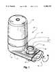
- FIG. 1is a perspective view of the water treatment device incorporating the present invention.
- FIG. 2is a front view of the water treatment device incorporating the present invention.
- FIG. 3is a top view of the water treatment device incorporating the present invention.
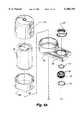
- FIGS. 4A-4Care an enlarged exploded view of the water treatment device incorporating the present invention.
- FIG. 5is a section taken along line 5--5 of FIG. 2.
- FIG. 6is a representational section view of the valve in the bypass position.
- FIG. 7is a section taken along line 7--7 of FIG. 3.
- FIG. 8is a section taken along line 8--8 of FIG. 5.
- FIG. 9is a section taken along line 9--9 of FIG. 5.
- FIG. 10is a representation partial section of the battery clips as shown in FIG. 8.
- FIG. 11is a section taken along line 11--11 of FIG. 10.
- FIG. 12is a representational partial section similar to FIG. 10, wherein the battery is removed from the clips.
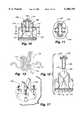
- FIG. 13is an enlarged perspective view of the battery clips as shown in FIG. 4B.
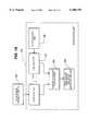
- FIG. 14is a functional block diagram of the meter system.
- FIG. 15is a flow chart indicating the operation of the meter system.
- FIG. 16is a schematic diagram of the flow sensor and the microcontroller of the meter system.
- FIG. 17is an enlarged perspective view of an alternative embodiment of the battery clips as shown in FIG. 4B.
- FIG. 18is an enlarged view of the turbine.
- FIG. 19is a section taken along lines 19--19 of FIG. 18.
- FIG. 20is an enlarged representational partial section of the second vertical channel and the surrounding structure.
- an end-of-faucet water treatment device 20which incorporates the water flow and time totalization meter system of the present invention.
- the water treatment devicehas a replaceable filter which is embodied in a mechanical and/or adsorptive filter cartridge for reducing undesirable contaminants from potable water supplies.
- the particular embodiment of the water treatment device described hereinis attached to the end of a kitchen sink faucet 22, and is more typically known as an end-of-faucet (EOF) filter.
- EAFend-of-faucet
- the totalization meter systemsums the volume of flow through the filter cartridge using a rotating turbine, as well as the total time since the meter system was reset.
- the water treatment deviceincludes a main body 24 defining a first non-filtered bypass flow path 26 (FIG. 6), and a second filtered flow path 28 (FIG. 7).
- the main bodyis attached to a water source, such as faucet 22, and defines a bypass outlet 30 and a filtered outlet 32.
- the meter system and a filter cartridgeare located in the main body in-line with the second filtered flow path 28.
- a valve 34is included in the main body 24 and is actuable to control the flow of the water between the first 26 and second 28 flow paths.
- the bypass 26 flow pathis selected, the water flows from the faucet 22 directly to the bypass outlet 30 and does not flow through the filter cartridge.
- the filtered flow path 28is selected, the water flows from the faucet 22, into the main body 24, through the filter cartridge, through the totalization system, and to the filtered outlet 32.
- the meter system 36 of the present inventioncollects data pertaining to the total volume of water flowing through the filter cartridge 38, and the total time since the meter system was last reset or activated.
- the total volume of water flowing through the meter system 36 and the total time since the system was last activatedare both indicative of the remaining life of the replaceable filter cartridge 38.
- This performance or status datais accumulated by the meter system 36 and output to the user through an output device 40 to indicate to the user the functional status of the filter cartridge 38.
- the water treatment deviceincludes a main body 24 having an upright portion 42 and a laterally extending portion 44 attached to the bottom of the upright portion.
- the laterally extending portion 44includes an inlet aperture 46 for receiving water from the water source, attachment structure 48 associated with the inlet aperture 46 for connecting the water treatment device 20 to the water source, such as the standard faucet 22, a valve 34 for directing the water along the first 26 or second 28 flow paths, and the bypass outlet aperture 30.
- the upright portion 42 of the main body 24forms, as best shown in FIGS. 7, 8 and 9, a vertically oriented chamber 50 which includes a top portion 52 for receiving the replaceable filter cartridge 38, a middle portion 54 for receiving the meter system 36, and a bottom portion 56 and the filtered outlet aperture 32.
- the main body 24is generally formed by a skeletal housing structure 58 having upright 60 and laterally 62 extending portions, analogous to the main body 24, and external shroud members, including the base 64, lower portion 66, riser 68 and cap 70.
- the skeletal housing structure 58contains, supports, and positions the filter cartridge 38 and meter system 36, while the external shroud members 64, 66, 68 and 70 mainly provide the desired aesthetic look.
- the top of the upright portion 60 of the skeletal structure 58is externally threaded to receive the internal threads of the top portion 70 of the housing shroud.
- the inlet aperture structure 48, bypass outlet aperture structure 30, and valve 34 structureare best shown in FIGS. 4A-C, 6 and 7.
- the inlet aperture 48 structureallows the water treatment device to releasably attach to the end of a standard faucet 22.
- the lateral extending portion 62 of the skeletal structure 58 and the lower portion 66 of the shroudboth define apertures for aligned orientation, which together form the inlet aperture 46.
- the aperture 72 on the lateral extending portion 62 of the skeletal structure 58includes an externally threaded collar 74 which extends upwardly through the aperture in the shroud.
- An insert bushing 76is sealingly mated with a washer 78 in the collar 74 to an interior annular shoulder formed around the aperture in the skeletal structure 58.
- the insert bushing 76has a radially outwardly extending flange, and internal threading terminating in a radially internally extending flange.
- the internal threading on the bushing 76receives the external threading on the faucet 22 to attach the water treatment device thereto.
- the end of the faucetbutts against the internally radially extending flange in the bushing 76 and is sealed therein with a washer 77.
- An internally threaded retaining nut 80engages the outwardly extending radial flange on the bushing 76, and threadedly engages the external threads on the collar 74 to clamp the bushing 76 and the rest of the assembly together in a watertight manner.
- the outlet apertureincludes a filter screen assembly 84, and retaining nut 86.
- the retaining nut 86threadedly attaches to an externally threaded collar 88 extending from the bypass aperture 30 on the laterally extending portion 62 of the skeletal structure 58.
- the collar 88extends downwardly through the outlet aperture 90 formed in the base portion 64 of the shroud.
- the retaining nut 86positions the washer and filter screen assembly in the bypass outlet aperture 30.
- the valve 34inserts into a longitudinal bore 92 formed in the lateral extension 62 of the skeletal structure 58, and when assembled therein directs the water to the first flow path 26 to bypass the filter cartridge 38, or directs the water to the second flow path 28 and through the filter cartridge 38.
- the valve 34includes a generally frustoconically shaped stem 94 terminating in a T-handle 96.
- An external shroud portion 98fits over the T-handle 96 to match the other parts of the external shroud.
- An annular groove 100is formed between the T-handle 96 and the stem 94, creating a section having a reduced diameter.
- the first groove structure 102which is part of the first flow path 26, is formed just below the inlet aperture and across the width of the stem 94, as shown in FIG. 6.
- the first groove structure 102allows the water to flow directly from the inlet aperture 62 through to the outlet aperture 30.
- the valve 34is actuated for the first flow path, the T-handle 96 is positioned to be flush, or in line with, the lateral extension 62 of the skeletal structure 58, as shown in FIGS. 1 and 6.
- the second groove structure 104which is part of the second flow path 28, is formed just below the inlet aperture 46 and along the length of the stem 94 to open into the bore 92 formed in the lateral extension 62 of the skeletal structure 58.
- the second groove structure 104is the beginning of the second, or filtered, flow path 28, which is described in more detail below.
- the two groove structures 102 and 104are formed in the stem 94 offset at 90 degrees from one another.
- the stem 94is rotatably received in the bore 92, and is axially maintained therein by the edges of the external shroud (lower 66 and bottom 64 portions) inserted into the annular groove 100 formed between the T-handle 96 and the stem 94.
- the appropriate water-tight seals (O-rings)are positioned on the stem 94 to inhibit water flow past the stem, or between the first 102 and second 104 groove structures.
- the second, or filtered, flow path 28generally runs from the inlet aperture 46, past the valve 34 in the second position, through the second groove structure 104, and into the bore formed in the laterally extending portion of the skeletal structure, as shown in FIG. 7. From this point, as shown in FIG. 7, the second flow path continues into the base of the upright portion 60 of the skeletal structure 58 and up into the filter cartridge 38. The second flow path continues from the filter cartridge 38 down through the meter system 36 and out the filtered outlet aperture 32 (FIGS. 8 and 9).
- the second flow pathruns through several different components in the skeletal housing structure 58.
- the second flow pathruns from the bore 92, through a tunnel 93 formed under the bottom edge of the upright portion 60 of the skeletal structure 58, up through a first vertically oriented channel 108 through the meter case 106, as shown in FIG. 7.
- the filter cartridgeis positioned above the meter case 106 and rests on a plurality of supports 107 extending upwardly from the meter case 106.
- the inlet port 110 of the filter cartridge 38is in fluid communication with the outlet 112 of the first vertical oriented channel 108 formed through the meter case 106.
- the second flow path 28continues through the filter cartridge 38 to the outlet port 114 of the filter cartridge 38, as shown in FIGS. 8 and 9.
- the outlet port 114 of the filter cartridge 38is in fluid communication with the inlet aperture 116 of the second vertical channel 118 formed through the meter case 106.
- the meter system 36is partially positioned in the second vertical channel 118, which has an outlet aperture 120 in fluid communication with the outlet, or filtered water, outlet aperture 32 for the second flow path 28.
- the filter cartridge 38can be made of any type of filter material that is normally used in this type of product.
- the flow path through the filter cartridge 38is not crucial to the working of this invention as long as the flow path terminates in an outlet port 114 formed in the filter cartridge 38.
- a preferable filter cartridge typeis fibrous activated carbon block, manufactured by Fibredyne Corporation of Dover, N.H.
- the waterflows radially through the filter cartridge 38 to a central cylindrical void, where the water falls under the force of gravity and pressure to the bottom of the filter cartridge and out the outlet port 114, as shown in FIG. 7.
- the meter case 106defines an internal cavity 122 which houses the meter system 36 of the present invention.
- the meter case 106also forms two legs of the second flow path 28: the first vertically oriented channel 108 to carry fluid to the inlet port 110 of the filter cartridge 38, and the second vertically oriented channel 118 to carry fluid from the outlet port 114 of the filter cartridge 38, past the meter system 36, to the filtered outlet 32.
- the two legs of the second flow pathare formed through the cavity 122 of the meter case 106, but do not allow fluid to pass into the cavity 122 itself.
- the meter case 106engages the base 124 of the skeletal structure 58.
- the meter case 106has a top surface 128 and a continuous side wall 130 attached around the perimeter of the top surface 128 and extending downwardly.
- the meter case 106fits in the upright portion 60 of the skeletal structure 58, engaging the base 124 around the circumference of the bottom edge 132 of the sidewall 130.
- the filter cartridge 38sits on the top of the meter case 106.
- the first vertical channel 108 of the second flow path 28 formed through the cavity 122is defined by a tube 134 extending upwardly from the base 124 to sealingly mate with an appropriately positioned aperture formed in the top surface 128 of the meter case 106.
- the aperture in the meter case 106is formed at the top of a short section 136 extending upwardly and downwardly from the meter case 106.
- the tube 134inserts into the bottom end of the short section 136 and engages a seal (such as an O-ring) to form a water-tight connection.
- a grommet 138is inserted into the aperture from the top of the short section 136 to engage a seal (such as an O-ring) in conjunction with the sidewalls of the inlet port 110 of the filter cartridge 38 to complete the water tight connection.
- a sealsuch as an O-ring
- the waterthus flows through the tunnel 93, through the tube 134, past the seals, through the grommet 138 and into the inlet port 110 of the filter cartridge 38.
- the second vertical channel 118 of the second flow path 28 formed in the meter case 106extends through the meter case 106 in line with the outlet port 114 of the filter cartridge 38, as best seen in FIGS. 8 and 9.
- the outlet aperture 120is formed in the base 124, and a corresponding aperture is formed in the meter case 106.
- the aperture formed in the meter case 106is formed at the top of a short section 140 extending upwardly and downwardly from the meter case 106.
- a grommet 139is inserted into the aperture from the top of the short section 140, and a seal is formed between the outer surface of the short section 140 and a cylindrical flange 142 extending downwardly from around the outlet port 110 of the filter cartridge 38, such as by an O-ring.
- a turbine housing 144extends upwardly around the outlet aperture 120 in the base 124, and defines opposing v-shaped axle-brackets 146, each having open top ends for rotatably supporting the cylindrical axle ends 147 extending from the turbine 148 therein, as described in greater detail below.
- a flow conditioner 150is positioned between the inlet aperture in the cover 126 and the top of the turbine housing 144.
- the flow conditioner 150includes a planar base 152 for engaging the top edge of the turbine housing 144, and an upwardly extending collar 154 for insertion into the section 140 extending downwardly from around the aperture formed in the cover 126.
- a sealis formed (such as by an 0-ring) between the flow conditioner 150 and the cover 126.
- a rim 154extends downwardly from the planar base 152 of the flow condition 150 to be received just inside the top edge of the turbine housing 144.
- Two prongs 156extend downwardly from the rim 154 of the flow conditioner 150 and terminate adjacent the axle brackets 146 when the flow conditioner 150 is in engagement with the turbine housing 144.
- the prongs 156retain the turbine 148 in the axle brackets 146 and keep the turbine 148 from becoming misaligned.
- An oval aperture 158is formed in the planar base 152 inside the collar for directing the fluid flow onto the proper portion of the turbine to affect rotation.
- the water flowing from the outlet port 114 of the filter cartridge 38thus flows through the grommet 139, through the aperture in the meter case 106, through the flow conditioner 150, through the turbine housing 144, past the meter system 36, and out the outlet aperture 32.
- the battery 160 for powering the meter system 36is suspended in the cavity 122 of the cassette 106 from the top surface 128 of the cover 126, as shown in FIGS. 4B, 8, 10 and 12.
- the batteryis preferably a CR2032 three-volt watch-type battery which is expected to operate for approximately 2 years when incorporated with the meter system of the present invention.
- a battery holder 162supports the battery 160 in a vertically oriented position through a slot 164 formed in the cover 126 of the cassette 106.
- the battery holder 162has a top member 166 for forming a seal to the top surface 128 of the cover 126, a grip portion 168 for providing a location to grasp the holder 162 to remove the battery 160 from the cassette 106, and a downwardly depending seat 170 which holds the battery 160 vertically.
- the seat 170has a circumferential rim to securely engage the outer periphery of the battery 160, and has open sides to allow contact with both sides of the battery 160.
- a pair of contact clips 172, 174automatically engage the battery 160 through the open sides in the holder 162 to provide and carry electrical power to the meter system 36.
- the contact clips 172, 174are positioned in the cassette 106 adjacent to the position of the battery 160 such that when the battery is inserted (FIG. 10), one clip 172, 174 contacts each side of the battery 160. When the battery 160 is removed, the clips 172, 174 extend to contact each other (FIG. 12).
- Each clip 172, 174as shown in FIGS. 8, 10-13, is a single length of wire having opposing ends and a centrally formed D-shaped spring contact 176, 178. The D-shaped spring contact 176, 178 extends from the top inwardly and downwardly to a free end.
- the bend in the wire at the topcreates the spring bias force to bias each spring contact 176, 178 inwardly to engage the other spring contact in the absence of the battery 160.
- the removal of the battery 160causes the spring contacts 176, 178 to engage one another and reset the meter system 36, as described in greater detail below.
- FIG. 17An alternative embodiment of the battery contact clips 172a and 174a are shown in FIG. 17. These contact clips are formed of sheet metal and have basically same shape and function as the above-described contact clips 172 and 174. The contact clips 172a and 174a are held in place by fasteners, such as screws, which attach through the ends of the each contact clip into the meter case 106. As shown in FIGS. 4B, 7, 8 and 9 the meter case 106 also includes a port 180 into which the output device 40 (such as an LED) of the meter system 36 is inserted when the meter case 106 is positioned on the base 124. The port 180 is positioned next to a lens 182 positioned in the riser portion 68 of the shroud.
- the output device 40such as an LED
- the LEDextends out of the port adjacent to the base of the lens.
- the lensis inserted to fit through an aperture 183 formed in the side wall of the shroud and a corresponding aperture in upright portion 60 of the skeletal structure.
- the base of the lensextends into the upright portion of the skeletal structure to terminate adjacent to the position of the LED extending through the port.
- the lensis preferably made of polycarbonate thermoplastic resin, or other light-transmissive material.
- the meter system 36is contained in part in the cavity 122 formed in the meter case 106, in conjunction with the turbine 148 positioned in the flow stream in the turbine housing 144.
- the meter system 36includes the rotatable turbine positioned in the flow stream, a sensor 184 and microcontroller 186, and an output device 40.
- the sensor 184, microcontroller 186 and output device 40are all positioned on a circuit board 188 that fits into the cassette 106, and are electrically connected to the battery 160.
- the meter system 36performs two basic record keeping functions. First, the meter system 36 counts the time from when the meter system was last reset. The meter system 36 is reset by removing and reinserting the battery. When the battery 160 is removed from the holder 162, the clips 172, 174 engage and reset the microcontroller 186 and the counters used therein.
- the meter system 36calculates the total flow of water through the filter cartridge 38 by monitoring the movement of the turbine 148. As described below, the turbine turns a known number of times per unit volume of water flowing past the turbine. Both of these functions are performed simultaneously, by the sensor 184 and microcontroller 186, as described in greater detail below.
- the turbine 148is rotatably positioned in the turbine housing 144, and has a signal generating member 190 mounted thereto.
- the turbineis Generally an elongated cylinder having radially extending turbine blades 192 formed along the length of the cylinder, as shown in FIGS. 18 and 19.
- One blade 192 of the turbine 148has a magnetic rod 190 positioned in its tip, the rod extending along the length of the blade 192.
- the turbine blades 192 opposite the one having the magnetic rod 190are designed to have greater mass (greater blade thickness dimension) in order to counterbalance the additional weight of the magnetic rod.
- the turbine 148has eight equally spaced blades, and the three blades opposite the blade with the magnetic rod positioned therein are thicker than the other blades. This feature is important since the turbine rotates at a relatively high frequency, and any imbalance in the rotational inertia would prove detrimental to the performance of the meter system 36, as well as the structural integrity of the turbine and the axle brackets 146. There are other means of balancing the turbine 148, such as placing a counter weight in an opposing blade, or other location, to obtain the desired counter-balance function.
- the turbine 148is positioned under the aperture 158 in the flow conditioner 150.
- the aperture 158is over an outer portion of the fins 192 of the turbine 148 so that the water flow impacts predominantly one side of the turbine 148 to cause it to turn in one direction only (counterclockwise in FIG. 9).
- the turbine 148 of the presently disclosed embodimentis approximately 3/8 inches long, 0.5 inches in diameter, with a fin length of approximately 1/8 inches.
- This turbine 148rotates approximately 6140 times per gallon of water that flows through the second vertically oriented channel.
- the error of the turbine rotation per gallon of wateris ⁇ 15%, and depends upon flow rate of the fluid. It is contemplated that the specific design of the turbine could be modified, which would change the relationship between the number of rotations and gallons of flow.
- the sensor 184 and microcontroller 186are formed of electrical components interconnected on a circuit board 188, which is positioned in the cavity 122 formed by the cassette 106, out of the flow of the water.
- the sensor 184such as a reed switch or hall-effect sensor, is positioned near the turbine housing 144 and adjacent to the turbine 148.
- the sensoris inside the cavity, while the turbine 148 is in the second vertically oriented channel 118, with the wall of the turbine housing 144 positioned therebetween.
- the sensor and microcontroller assemblyis thus maintained in a relatively dry condition to minimize the detrimental effects of the water on the performance of the meter system 36.
- FIG. 14is a functional block diagram of the sensor and microcontroller, and shows a microcontroller 186 having a flow counter 194, a time counter 196, a sleep/wake timer 198, an age/totalizer module 200, and an output module 202.
- the flow counter 194is responsive to the external flow sensor 184 and counts the number of rotations of the turbine 148 during operation of the water treatment device 20.
- the time counter 196is responsive to the sleep/wake timer 198 to periodically count real time increments.
- the age/totalizer module 200responsive to the flow counter 194 and the time counter 196, calculates the total amount of time which water is passed through the filter cartridge 38 of the water treatment device 20, as well the total amount of fluid passed through the filter cartridge 38.
- the output module 202is used to control the output device 40 to provide the proper user information as previously described.
- the values from the flow counter 194 and the time counterare maintained in the microcontroller 186 until the battery 160 is removed and reinserted to reset the microcontroller.
- the sleep/wake timer 198cycles the microcontroller 186 between a low-power sleep state and a wake state.
- the microcontrollerIn the sleep state, the microcontroller enters its lowest power operation mode and awaits the wake mode, thereby reducing the microcontroller's power consumption from the battery 160 (i.e., to 3 micro-amps or less).
- the microcontroller 186In the wake mode, the microcontroller 186 resumes normal operation and measures any water flow, updates the time counter 196, and performs various calculations, described below.
- the flow sensor 184can sense, through the wall of the turbine housing 144, the movement of the magnetic rod 190 as it rotates, thus generating a signal indicative of the number of, and the frequency of, the rotations of the turbine 148 as it is driven by the water flowing through the second flow path 28.
- the flow sensor 184sends the signal containing this information to the flow counter 194, which records the total flow past the turbine 148, and thus through the filter cartridge 38.
- the flow sensor 194generates and sends a signal containing the turbine rotation information to the age/totalizer module 200, which converts the rotation information to total flow information via a known rotation-to-flow relationship, known as the first performance data. This information is used for several purposes, including for comparison against the respective threshold data in the programmed controller.
- the timer 198operates according to the flow chart in FIG. 15 to control the time counter 196, which tracks the elapsed time since the meter system was reset or started (by pulling and replacing the battery).
- This total time recorded and stored by the time counter 196is translated into a signal, which is sent to the age/totalizer module 200, and is the second performance data.
- the age/totalizer module 200compares the data in the signals received from the flow counter 194 and the time counter 196, and determines the status of the filter cartridge 38 against the pre-programmed threshold requirements. Based on the status of the filter cartridge 38, the output device 40 is actuated accordingly to transmit the information to the user.
- the microcontrolleris pre-programmed to include threshold data levels for total time elapsed, and total flow, since resetting the microcontroller. There may be several sets of threshold requirements pre-programmed into the microcontroller for different output signals.
- the microcontrolleris programmed to: 1) actuate the output device 40 to blink green (acceptable signal) when the filter cartridge 38 is less than or equal to 90% "used," as determined by flow volume (180 gallons) or time (81 days); 2) delay actuation (delay signal) of the output device per 1) above for 3 seconds each time the turbine 148 transitions from resting state to a rotating state; 3) actuate the output device 40 to blink yellow (flush signal) for 2 minutes where the meter system 36 has just previously been reset and the turbine 148 transitions from a resting stated to a rotating state; 4) actuate the output device 40 to blink yellow (caution signal) when the filter cartridge is greater than 90% "used” and less than 100% "used,” as determined by either flow volume (180+ gallons) or time (81+ days); and 5) actuate the output device 40 to blink red (terminate signal) when the filter cartridge 38 is 100% "used
- the microcontrolleris pre-programmed according to the above information to include the appropriate threshold requirements for comparison to the flow and time data for the proper output signal.
- the above threshold requirementshave been found to be desirable from a utilitarian and commercial perspective. It is contemplated that other threshold requirements can be programmed into the microcontroller.
- the flow counter 194 and the time counter 196provide this information to the age/totalizer module 200 to compare against the appropriate performance threshold data programmed in the microcontroller to determine the proper status for the output device 40.
- a meter system 36 for a water treatment device 20is described, the device having an inlet aperture 46 and an outlet aperture 32, and a flow path 28 for channeling water between the inlet 46 and outlet 32 apertures.
- a flow reactive device 148such as a turbine or paddle wheel, is positioned in the path 28 and exposed to the flowing water, and a signal generating member 190, such as a magnetic member, is positioned on the flow reactive device 148.
- a sensor 184 or switch, such as a reed switch,is positioned proximately to the flow reactive device 148, and is sensitive to the proximity of the signal generating member 190. The sensor 184 is able to communicate electric signals indicative of the motion of the signal generating member 190.
- the resettable microcontrollerhas at least one performance threshold programmed therein.
- the performance thresholdcould be the total flow or the total time allowed for the filter cartridge 38 in the particular water treatment device 20.
- the microcontroller 186is in electrical communication with the sensor 184 for receiving electrical signals from the sensor 184.
- the sensor 184is capable of sensing the characteristics of the flow reactive device 148 and communicates electrical signals representative of these characteristics to the microcontroller 186.
- the microcontroller 186interprets the signals as a first performance data, the microcontroller also having a time counter 196 for totaling the time lapse since the microcontroller was last reset.
- the microcontrollerinterprets the time lapse as a second performance data, and the microcontroller compares the first performance data and the second performance data against the respective performance threshold to determine if the performance threshold has been surpassed by either the first or second performance data. If the respective threshold data was surpassed, the microcontroller 186 actuates the output device 40 to display to the user the status of the cartridge filter in the water treatment device 20.
- first and second (90% time and flow limits) and a set of third and fourth (100% time and flow limits) performance thresholdsprogrammed into the microcontroller 186, each set having their own respective output signals.
- the microcontrollercompares the first performance data (flow) and the second performance data (time) against the set of first and second performance thresholds, and against the set of third and fourth performance thresholds to determine which set of thresholds has been surpassed. If either set of performance thresholds have been surpassed by either the first or second performance data, the microcontroller actuates the output device 40 to display the respective output signal.
- FIG. 15is a flow chart of the operation of the microcontroller 186 in controlling and sequencing the operation of the meter system 36 as shown in the functional block diagram of FIG. 14.
- the methodstarts with the Start Reset or Wake 204 operation, and moves to the Wake or Reset? decisional operation 206. If the status here is reset, then move to the Initialize Variables 208 operation and perform the Sleep for 1 Second operation 210. The Sleep for 1 Second Operation 210 loops back to the Start Reset or Wake Operation 204.
- FIG. 16is a circuit diagram illustrating an embodiment of the electrical components of the meter system.
- the microcontroller 100has an oscillator input (OSC1), a master clear (MCLR) input which resets the processor, and configurable input/output pins shown as IO1, IO2, IO3, and IO4.
- OSC1oscillator input
- MCLRmaster clear input/output pins
- IO1, IO2, IO3, and IO4configurable input/output pins
- An 8-bit microcontroller model PIC 16C54 from the Microchip Companycan be used for microcontroller 186.
- the battery 160establishes the power supply for the processor 186 when placed across the contact clips 172.
- a standard filtering capacitoris placed in parallel with the battery 160 to minimize ripples in the supply voltage.
- the oscillator input OSC1 of microcontroller 186is biased with a resistor and capacitor to establish a known and reliable clock cycle which is used to derive the time base from which the calculations are made within microcontroller 186.
- Microcontroller 186is resettable when the MCLR pin (active low) is set low. As previously described, contact clips 172, 174 are spring loaded such that when battery 162 is removed, the contact clips connect the MCLR pin to ground, thereby resetting the processor and the values stored therein, but not the threshold data stored therein.
- Sensor 184which closes in response to magnetic member 190, is connected to two bi-directional configurable input/output pins IO1 and IO2.
- the IO2 pinis configured as an input pin and the IO1 pin is configured as an output pin.
- the microcontroller 186seeks to determine whether switch 184 is opened or closed, a logic high signal is placed on the IO1 pin, and the logic level present on the IO2 pin is read by the microcontroller 186. If the logic level on the IO2 pin is low, then switch 184 is closed; conversely, if the logic level on the IO2 pin is high, switch 184 is opened.
- the IO1 pinis a reconfigurable input/output pin
- the high logic level output at pin IO1is released by the microcontroller when the microcontroller is not reading the state of switch 184. In this manner, the amount of power consumed when reading switch 184 is reduced.
- Input/output pins IO3 and IO4are both configured as output pins to drive the output device 40, such as LED 236.
- LED 236can consist of a combination of LEDs to provide the appropriate output signals, or colors, as needed.
- FIG. 16shows a microcontroller 186 and associated circuitry for implementing the operations and functions described herein, it is understood that equivalent microcontrollers, microprocessors, controllers, processors, discrete logic, real time counters or other electronic counting devices and associated circuitry could also be used without departing from the scope of the present invention.
- the meter system 36is reset or initialized by removing and reinserting the battery 160. This is accomplished by grasping the grip portion 168 of the holder 162 and removing the holder from the slot 164 in the top of the cassette 106. When the battery 160 is removed, the spring contacts 176, 178 touch one another and reset the totalizer system to an initial condition.
- the meter system 36initiates two counter functions for simultaneous operation in the meter system: 1) the total flow counter and 2) the time counter.
- the total flow counteris driven by the amount of water passing the turbine 148, determining the number of rotations of the turbine 148.
- the number of rotations of the turbineis sensed by the sensor 184 and is accumulated and converted in the meter system 36 into total gallons.
- the time counterstarts once the battery is re-inserted, with the lapsed time since re-insertion being stored and accumulated in the meter system 36.
- the meter system 36is programmed to output certain signals through the output device 40 depending on the status of the total flow or total time as measured.
- the systembeneficially alerts the user to the status of the filter cartridge performance in the filter unit to provide information on when to change the filter cartridge, or on when to plan on purchasing a new filter cartridge to replace an existing filter cartridge soon to expire.
- the meter systemcan preferably provide the following information:
- Activate a first signale.g. blink green
- a first signale.g. blink green
- the filter cartridge 38is within the flow and time limits (i.e. less than 90% flow or use thresholds).
- Activate a second signale.g. blink yellow
- a second signale.g. blink yellow
- Activate a third signale.g. blink red
- a third signale.g. blink red
- Activate a fourth signale.g. blink yellow
- a fourth signale.g. blink yellow
Landscapes
- Chemical & Material Sciences (AREA)
- Chemical Kinetics & Catalysis (AREA)
- Physics & Mathematics (AREA)
- Environmental & Geological Engineering (AREA)
- Organic Chemistry (AREA)
- Water Supply & Treatment (AREA)
- Life Sciences & Earth Sciences (AREA)
- Hydrology & Water Resources (AREA)
- Engineering & Computer Science (AREA)
- Health & Medical Sciences (AREA)
- Clinical Laboratory Science (AREA)
- Thermal Sciences (AREA)
- Electromagnetism (AREA)
- Fluid Mechanics (AREA)
- General Physics & Mathematics (AREA)
- Measuring Volume Flow (AREA)
- Water Treatment By Sorption (AREA)
Abstract
Description
Claims (7)
Priority Applications (4)
| Application Number | Priority Date | Filing Date | Title |
|---|---|---|---|
| US09/346,164US6106705A (en) | 1997-08-08 | 1999-07-01 | Water treatment device with volumetric and time monitoring features |
| US09/629,876US6284129B1 (en) | 1997-08-08 | 2000-08-01 | Water treatment device with volumetric and time monitoring features |
| US09/903,054US6517707B2 (en) | 1997-08-08 | 2001-07-10 | Water treatment device with volumetric and time monitoring features |
| US10/364,299US6926821B2 (en) | 1997-08-08 | 2003-02-10 | Water treatment device with volumetric and time monitoring features |
Applications Claiming Priority (2)
| Application Number | Priority Date | Filing Date | Title |
|---|---|---|---|
| US08/907,683US5935426A (en) | 1997-08-08 | 1997-08-08 | Water treatment device with volumetric and time monitoring features |
| US09/346,164US6106705A (en) | 1997-08-08 | 1999-07-01 | Water treatment device with volumetric and time monitoring features |
Related Parent Applications (1)
| Application Number | Title | Priority Date | Filing Date |
|---|---|---|---|
| US08/907,683ContinuationUS5935426A (en) | 1997-08-08 | 1997-08-08 | Water treatment device with volumetric and time monitoring features |
Related Child Applications (1)
| Application Number | Title | Priority Date | Filing Date |
|---|---|---|---|
| US09/629,876ContinuationUS6284129B1 (en) | 1997-08-08 | 2000-08-01 | Water treatment device with volumetric and time monitoring features |
Publications (1)
| Publication Number | Publication Date |
|---|---|
| US6106705Atrue US6106705A (en) | 2000-08-22 |
Family
ID=25424473
Family Applications (5)
| Application Number | Title | Priority Date | Filing Date |
|---|---|---|---|
| US08/907,683Expired - LifetimeUS5935426A (en) | 1997-08-08 | 1997-08-08 | Water treatment device with volumetric and time monitoring features |
| US09/346,164Expired - LifetimeUS6106705A (en) | 1997-08-08 | 1999-07-01 | Water treatment device with volumetric and time monitoring features |
| US09/629,876Expired - LifetimeUS6284129B1 (en) | 1997-08-08 | 2000-08-01 | Water treatment device with volumetric and time monitoring features |
| US09/903,054Expired - LifetimeUS6517707B2 (en) | 1997-08-08 | 2001-07-10 | Water treatment device with volumetric and time monitoring features |
| US10/364,299Expired - LifetimeUS6926821B2 (en) | 1997-08-08 | 2003-02-10 | Water treatment device with volumetric and time monitoring features |
Family Applications Before (1)
| Application Number | Title | Priority Date | Filing Date |
|---|---|---|---|
| US08/907,683Expired - LifetimeUS5935426A (en) | 1997-08-08 | 1997-08-08 | Water treatment device with volumetric and time monitoring features |
Family Applications After (3)
| Application Number | Title | Priority Date | Filing Date |
|---|---|---|---|
| US09/629,876Expired - LifetimeUS6284129B1 (en) | 1997-08-08 | 2000-08-01 | Water treatment device with volumetric and time monitoring features |
| US09/903,054Expired - LifetimeUS6517707B2 (en) | 1997-08-08 | 2001-07-10 | Water treatment device with volumetric and time monitoring features |
| US10/364,299Expired - LifetimeUS6926821B2 (en) | 1997-08-08 | 2003-02-10 | Water treatment device with volumetric and time monitoring features |
Country Status (2)
| Country | Link |
|---|---|
| US (5) | US5935426A (en) |
| UA (1) | UA73272C2 (en) |
Cited By (30)
| Publication number | Priority date | Publication date | Assignee | Title |
|---|---|---|---|---|
| US6517707B2 (en) | 1997-08-08 | 2003-02-11 | Water Pik, Inc. | Water treatment device with volumetric and time monitoring features |
| US6610121B2 (en) | 2002-01-09 | 2003-08-26 | Hp Intellectual Corp. | Odor removal system |
| US6660060B2 (en) | 2002-01-09 | 2003-12-09 | Hp Intellectual Corp. | Air filtering system |
| US20040069696A1 (en)* | 2002-09-09 | 2004-04-15 | William Warren | Single-use long-life faucet-mounted water filtration devices |
| US6753186B2 (en)* | 2001-03-16 | 2004-06-22 | Ewatertek Inc. | Water quality monitoring and transmission system and method |
| US20040201485A1 (en)* | 2003-04-10 | 2004-10-14 | John Dermody | Air filter timer |
| USD498511S1 (en) | 2003-07-03 | 2004-11-16 | Clear Flow Corporation | Water filter |
| USD498512S1 (en) | 2003-07-03 | 2004-11-16 | Clear Flow Corporation | Water filter |
| US20050092661A1 (en)* | 2002-09-09 | 2005-05-05 | William Warren | Single-use long-life faucet-mounted water filtration devices |
| US20050279676A1 (en)* | 2004-06-21 | 2005-12-22 | Izzy Zuhair A | Fluid filter assembly for a dispensing faucet |
| WO2006011134A3 (en)* | 2004-07-26 | 2006-07-13 | Ap2U Net Ltd | A liquid supply measuring apparatus |
| USD533622S1 (en) | 2003-10-01 | 2006-12-12 | Water Pik, Inc. | End-of-faucet filter |
| USD541372S1 (en) | 2005-11-01 | 2007-04-24 | Clarity Filters Llc | Water filter |
| USD541374S1 (en) | 2005-11-30 | 2007-04-24 | The Clorox Company | Faucet mounted water filter |
| USD542374S1 (en) | 2005-11-30 | 2007-05-08 | The Clorox Company | Faucet mounted water filter |
| US20070182159A1 (en)* | 2005-08-01 | 2007-08-09 | Davis Chief R | Sewer line power generating system |
| US7326334B2 (en) | 2003-10-01 | 2008-02-05 | Instapure Brands, Inc. | End-of-faucet filter |
| USD570951S1 (en)* | 2006-11-28 | 2008-06-10 | Mrc Home Products Co., Ltd. | Cartridge for water purifier |
| USD583612S1 (en) | 2007-05-21 | 2008-12-30 | Applica Consumer Products, Inc. | Water filtration pitcher |
| WO2009121072A1 (en)* | 2008-03-28 | 2009-10-01 | Showerminder, Llc | Indicating a shower stage |
| US20100230969A1 (en)* | 2004-07-26 | 2010-09-16 | Ap2U.Net.Ltd. | Apparatus for transforming energy of liquid flowing in a liquid supply pipeline |
| US20110221197A1 (en)* | 2004-07-26 | 2011-09-15 | Hydrospin Monitoring Solutions Ltd. | Apparatus for transforming energy of liquid flowing in a liquid flow path |
| EP2386854A1 (en) | 2005-04-19 | 2011-11-16 | Prediction Sciences LLC | Diagnostic markers of breast cancer treatment and progression and methods of use thereof |
| US20190219276A1 (en)* | 2018-01-15 | 2019-07-18 | Advanced Conservation Technologies Distribution, Inc. | Fluid Distribution System |
| US10473494B2 (en) | 2017-10-24 | 2019-11-12 | Rain Bird Corporation | Flow sensor |
| US20200008609A1 (en)* | 2016-12-20 | 2020-01-09 | Koninklijke Douwe Egberts B.V. | Drainage connector unit and assembly for the drainage of liquid waste of beverage dispensing devices |
| US10634538B2 (en) | 2016-07-13 | 2020-04-28 | Rain Bird Corporation | Flow sensor |
| US11662242B2 (en) | 2018-12-31 | 2023-05-30 | Rain Bird Corporation | Flow sensor gauge |
| US11874149B2 (en) | 2020-04-27 | 2024-01-16 | Rain Bird Corporation | Irrigation flow sensor systems and methods of detecting irrigation flow |
| US12443208B2 (en) | 2023-02-08 | 2025-10-14 | Rain Bird Corporation | Control zone devices, systems and methods |
Families Citing this family (102)
| Publication number | Priority date | Publication date | Assignee | Title |
|---|---|---|---|---|
| US6093313A (en)* | 1996-12-06 | 2000-07-25 | Moen Incorporated | Multiple discharge water faucet with self-contained filter |
| US6149801A (en) | 1997-08-08 | 2000-11-21 | Water Pik, Inc,. | Water treatment device with volumetric monitoring features |
| CA2318636C (en)* | 1998-01-21 | 2008-05-13 | The Clorox Company | Faucet mounted water filter |
| US6251274B1 (en)* | 1999-03-16 | 2001-06-26 | Envirogard Products Limited | Faucet attachment for treating water |
| US6258266B1 (en)* | 1999-04-21 | 2001-07-10 | Sta-Rite Industries, Inc. | Faucet mount water filtration device |
| US7229550B2 (en)* | 1999-04-23 | 2007-06-12 | Haase Richard A | Potable water treatment system and apparatus |
| US6375834B1 (en)* | 1999-06-30 | 2002-04-23 | Whirlpool Corporation | Water filter monitoring and indicating system |
| US6355177B2 (en)* | 2000-03-07 | 2002-03-12 | Maytag Corporation | Water filter cartridge replacement system for a refrigerator |
| US6328881B1 (en) | 2000-03-08 | 2001-12-11 | Barnstead Thermolyne Corporation | Water purification system and method including dispensed volume sensing and control |
| US6379560B1 (en) | 2000-03-08 | 2002-04-30 | Barnstead/Thermodyne Corporation | Water purifying apparatus and method for purifying water |
| USRE40310E1 (en) | 2000-03-08 | 2008-05-13 | Barnstead Thermolyne Corporation | Water purification system and method including dispensed volume sensing and control |
| US6306290B1 (en)* | 2000-06-26 | 2001-10-23 | Patrick J. Rolfes | Water filter replacement indicator |
| JP2002205061A (en)* | 2001-01-15 | 2002-07-23 | Toray Ind Inc | Water cleaning device |
| US6881333B2 (en) | 2001-03-26 | 2005-04-19 | Osaka Gas Chemicals Co., Ltd. | Water purifier filtration portion, water purifier main body, and water purifier including the both |
| US6736298B2 (en)* | 2001-04-07 | 2004-05-18 | Oasis Corporation | Thermoelectric water cooler with filter monitor system |
| US7615152B2 (en) | 2001-08-23 | 2009-11-10 | Pur Water Purification Products, Inc. | Water filter device |
| US7614507B2 (en) | 2001-08-23 | 2009-11-10 | Pur Water Purification Products Inc. | Water filter materials, water filters and kits containing particles coated with cationic polymer and processes for using the same |
| US7614508B2 (en) | 2001-08-23 | 2009-11-10 | Pur Water Purification Products Inc. | Water filter materials, water filters and kits containing silver coated particles and processes for using the same |
| US20050279696A1 (en) | 2001-08-23 | 2005-12-22 | Bahm Jeannine R | Water filter materials and water filters containing a mixture of microporous and mesoporous carbon particles |
| KR100777951B1 (en) | 2001-08-23 | 2007-11-28 | 더 프록터 앤드 갬블 캄파니 | Water filter material, corresponding water filter and method of use thereof |
| WO2003037479A1 (en)* | 2001-10-13 | 2003-05-08 | Professional Dental Manufacturing, Inc. | Water filtering apparatus |
| US7638042B2 (en)* | 2002-02-15 | 2009-12-29 | 3M Innovative Properties Company | System for monitoring the performance of fluid treatment cartridges |
| DE10216847B4 (en)* | 2002-04-16 | 2007-09-20 | Water-Planet Gmbh | Filter device and filter device |
| DE10254054A1 (en)* | 2002-11-19 | 2004-06-03 | Endress + Hauser Flowtec Ag, Reinach | Device for determining and / or monitoring the volume and / or mass flow of a medium |
| US6860988B2 (en)* | 2002-12-23 | 2005-03-01 | Envirogard Products Ltd. | Fluid filtration system with fluid flow meter |
| US7094334B1 (en) | 2003-05-21 | 2006-08-22 | H2O International Inc. | Water filter having a filter use time indicator |
| US7249524B2 (en)* | 2003-05-27 | 2007-07-31 | Williams Richard T | Fluid flow rate and volume sensor, and filtration apparatuses and purification apparatuses having such a sensor |
| US7775422B2 (en) | 2003-06-13 | 2010-08-17 | Arad Measuring Technologies Ltd. | Meter register and remote meter reader utilizing a stepper motor |
| US20060108267A1 (en)* | 2003-07-03 | 2006-05-25 | William Warren | Single-use long-life faucet-mounted water filtration devices |
| US20050035054A1 (en)* | 2003-08-12 | 2005-02-17 | Yi-Chin Chu | Skincare device for filtering tapwater |
| USD501912S1 (en) | 2003-08-19 | 2005-02-15 | Procter & Gamble | Water filter device |
| KR101272966B1 (en) | 2003-10-17 | 2013-06-10 | 액세스 비지니스 그룹 인터내셔날 엘엘씨 | Diverter valve assembly and method of diverting a flow of fluid |
| US20050100483A1 (en)* | 2003-11-12 | 2005-05-12 | Cytyc Corporation | Specimen filter container having data storage |
| US7048129B2 (en)* | 2003-11-24 | 2006-05-23 | Skillings Roger B | System and method for processing liquid |
| DE602005003553T2 (en)* | 2004-01-27 | 2008-12-11 | Koninklijke Philips Electronics N.V. | AUDIO VIDEO CONTENT SYNCHRONIZATION BY PLAYLISTS |
| US7487677B2 (en)* | 2004-04-19 | 2009-02-10 | Fook Tin Technologies Ltd. | Apparatus and methods for monitoring water consumption and filter usage |
| US7107838B2 (en)* | 2004-04-19 | 2006-09-19 | Fook Tin Technologies Ltd. | Apparatus and methods for monitoring water consumption and filter usage |
| US7650830B1 (en)* | 2004-08-19 | 2010-01-26 | Miracle Spring LLC | Beneficiated water system |
| US7267014B2 (en) | 2004-09-23 | 2007-09-11 | Arad Measuring Technologies Ltd. | Meter register having an encoder |
| NL1027748C2 (en)* | 2004-12-15 | 2006-06-22 | Prolix Entpr Internat N V | Shower facility with protection against legionella. |
| US7497957B2 (en)* | 2005-01-21 | 2009-03-03 | Bernard Frank | System, method and apparatus for end-to-end control of water quality |
| US7442297B2 (en)* | 2005-02-28 | 2008-10-28 | Barnstead/Thermolyne Corp. | Remote water dispensing device and methods for operating such remote water dispensing devices |
| AU2006232547A1 (en)* | 2005-04-01 | 2006-10-12 | Applica Consumer Products, Inc. | Water filtration system with improved performance |
| US7743788B2 (en)* | 2005-06-17 | 2010-06-29 | Watts Regulator Co. | Faucet assembly with water quality indicator |
| US20070023332A1 (en)* | 2005-07-28 | 2007-02-01 | Huan-Chang Fan | Automatic supply filtered water adapting system |
| US7387083B2 (en)* | 2005-12-06 | 2008-06-17 | Life Science Control Corporation | Precision watering method and apparatus |
| SE529725C2 (en)* | 2006-03-16 | 2007-11-06 | Oilquick Ab | Hydraulic coupling device and its components and method |
| US20070277530A1 (en)* | 2006-05-31 | 2007-12-06 | Constantin Alexandru Dinu | Inlet flow conditioner for gas turbine engine fuel nozzle |
| US7568874B2 (en)* | 2006-06-02 | 2009-08-04 | Pur Water Purification Products, Inc. | Nut for attaching two devices and method for providing the same |
| USD629865S1 (en) | 2008-04-17 | 2010-12-28 | The Procter & Gambple Company | Connector for a faucet mounted water filter |
| USD582763S1 (en) | 2006-06-02 | 2008-12-16 | Pur Water Purification Products, Inc. | Threaded nut |
| USD568149S1 (en)* | 2007-07-23 | 2008-05-06 | Pur Water Purification Products, Inc. | Threaded nut |
| USD629487S1 (en) | 2008-04-17 | 2010-12-21 | The Procter & Gamble Company | Connector for a faucet mounted water filter |
| US7699993B2 (en)* | 2006-09-29 | 2010-04-20 | Barnstead Thermolyne Corporation | Methods for wirelessly operating water purification systems |
| US7824543B2 (en)* | 2006-09-29 | 2010-11-02 | Barnstead Themolyne Corporation | Wireless water purification systems and wireless remote dispensing devices for water purification systems |
| US9371245B2 (en) | 2006-10-12 | 2016-06-21 | Bruce D. Burrows | Drainless reverse osmosis water purification system |
| US7837866B2 (en)* | 2006-10-12 | 2010-11-23 | Burrows Bruce D | Drainless reverse osmosis water purification system |
| US8398852B2 (en)* | 2006-10-12 | 2013-03-19 | Bruce D. Burrows | Drainless reverse osmosis water purification system |
| WO2009033048A2 (en) | 2007-09-05 | 2009-03-12 | Pur Water Purification Products, Inc. | Apparatus and methods for faucet-mounted water filtration systems |
| US20090168290A1 (en)* | 2007-12-28 | 2009-07-02 | Patrick Dale Riedlinger | Battery clip wtih integrated microprocessor reset switch and method of operating |
| US8051723B2 (en)* | 2008-04-11 | 2011-11-08 | Performance Meter, Inc. | Encoder-type register for an automatic water meter reader |
| DE102008023488C5 (en) | 2008-05-14 | 2021-12-09 | Bwt Water+More Gmbh | Water filter device |
| WO2010048412A1 (en)* | 2008-10-22 | 2010-04-29 | Glenn Cueman | Reusable water filter systems and methods |
| EP2384313A4 (en)* | 2009-01-03 | 2013-04-17 | Gen Ecology Inc | METHODS AND MEANS FOR ECONOMICALLY ENSURING ENHANCED DRINKING WATER QUALITY MANAGEMENT FOR AIRCRAFT AND OTHER APPLICATIONS |
| US9845259B2 (en)* | 2009-01-03 | 2017-12-19 | General Ecology, Inc. | Apparatus for filtering and/or conditioning and/or purifying a fluid such as water |
| US8877056B2 (en)* | 2009-03-25 | 2014-11-04 | General Ecology, Inc. | Methods and means for economically assuring improved potable water quality management for aircraft and other applications |
| CN104692570A (en)* | 2009-01-12 | 2015-06-10 | 捷通国际有限公司 | Point-of-use water treatment system |
| US8482409B2 (en) | 2009-11-19 | 2013-07-09 | Masco Corporation Of Indiana | System and method for conveying status information regarding an electronic faucet |
| KR101164159B1 (en)* | 2010-03-11 | 2012-07-11 | 웅진코웨이주식회사 | Water purifying filter assembly module |
| USD637693S1 (en) | 2010-08-18 | 2011-05-10 | The Procter & Gamble Company | Connector for a faucet mounted water filter |
| USD637691S1 (en) | 2010-08-18 | 2011-05-10 | The Procter & Gamble Company | Connector for a faucet mounted water filter |
| USD637690S1 (en) | 2010-08-18 | 2011-05-10 | The Procter & Gamble Company | Connector for a faucet mounted water filter |
| EP2865635B1 (en) | 2011-02-16 | 2017-02-01 | Crown Equipment Corporation | Materials handling vehicle estimating a speed of a movable assembly from a lift motor speed |
| USD676766S1 (en) | 2011-05-10 | 2013-02-26 | Brita Lp | Filter indicator |
| US8865001B2 (en) | 2011-10-24 | 2014-10-21 | Water-Right, Inc. | Proportional regeneration for water treatment systems |
| US9758387B2 (en) | 2011-06-02 | 2017-09-12 | Water-Right, Inc. | Methods related to proportional regeneration of water treatment systems |
| US8546709B2 (en)* | 2011-06-13 | 2013-10-01 | Day Sun Industrial Corp. | Structure for preventing misoperation of flashlight |
| US8950188B2 (en) | 2011-09-09 | 2015-02-10 | General Electric Company | Turning guide for combustion fuel nozzle in gas turbine and method to turn fuel flow entering combustion chamber |
| TW201314089A (en)* | 2011-09-26 | 2013-04-01 | Rui-Qian Chen | Monitoring device for faucet, faucet having monitoring device and monitoring method thereof |
| US8961781B2 (en) | 2011-09-29 | 2015-02-24 | Brita Lp | Filter status techniques adapted for use with a container based filtration device |
| USD684256S1 (en)* | 2012-09-13 | 2013-06-11 | Moldex-Metric, Inc. | Cover for a respiratory cartridge |
| US10183874B2 (en) | 2013-12-18 | 2019-01-22 | Ds Services Of America, Inc. | Water purification system with active vibration |
| USD726001S1 (en)* | 2014-02-21 | 2015-04-07 | Monte Cristo Holdings, Llc | Sealing washer |
| US10060775B2 (en) | 2014-03-10 | 2018-08-28 | Driblet Labs, LLC | Smart water management system |
| WO2015138888A2 (en) | 2014-03-14 | 2015-09-17 | Protect Plus, Llc | Reusable water filter cartridge device |
| USD741163S1 (en)* | 2014-03-14 | 2015-10-20 | Bmt Co., Ltd. | Check ring for indicating nut tightening amount |
| WO2016020909A1 (en)* | 2014-08-04 | 2016-02-11 | Broner Moshe | An apparatus for monitoring liquid transportation vessels and liquid flowing through them |
| US10124350B2 (en)* | 2015-04-20 | 2018-11-13 | Ying Lin Cai | Hand-held shower head capable of measuring and suggesting replacement of filtering core handle |
| BR112017022999A2 (en) | 2015-05-22 | 2018-07-24 | Access Business Group Int Llc | point of use water treatment system |
| EP3153824B1 (en)* | 2015-10-05 | 2018-08-01 | Honeywell Technologies Sarl | Water treatment armature |
| JP1575701S (en)* | 2016-08-31 | 2017-05-08 | ||
| JP1575700S (en)* | 2016-08-31 | 2017-05-08 | ||
| USD823433S1 (en)* | 2017-01-20 | 2018-07-17 | Aquamedix Llc | Faucet filter |
| US11266932B2 (en) | 2017-01-20 | 2022-03-08 | Aquamedix Llc. | Faucet filtration system and related methods |
| US10288466B2 (en) | 2017-06-30 | 2019-05-14 | Sentry Equipment Corp. | Flow totalizer |
| US11933649B2 (en) | 2019-04-10 | 2024-03-19 | Task Force Tips, Llc | Measuring device with self-powering annular turbine |
| USD969964S1 (en) | 2020-03-06 | 2022-11-15 | Pentair Residential Filtration, Llc | Filtration system |
| FR3108414B1 (en)* | 2020-03-18 | 2022-06-10 | Vernet | Instrumented device for a mixer tap, as well as mixer tap comprising such an instrumented device |
| EP3909917A1 (en)* | 2020-05-15 | 2021-11-17 | Tapp Water S.L. | Filtering and quality monitoring of liquid in real-time |
| US12076671B2 (en)* | 2020-06-23 | 2024-09-03 | Cytiva Us Llc | Filter arrangement including prefiltration filter element and filter device |
| CN113532093B (en)* | 2021-07-19 | 2023-06-02 | 云南佳松新能源科技有限公司 | Temperature-changing drying equipment for medium-temperature heat pump |
| USD1072182S1 (en)* | 2024-03-08 | 2025-04-22 | Wouldn't It Be Nice LLC | Shower filter |
Citations (131)
| Publication number | Priority date | Publication date | Assignee | Title |
|---|---|---|---|---|
| US35667A (en)* | 1862-06-24 | Improvement in folding and tucking gages for sewing-machines | ||
| US329064A (en)* | 1885-10-27 | Filtering apparatus | ||
| US535817A (en)* | 1895-03-19 | Water-filter | ||
| US606804A (en)* | 1898-07-05 | Water-filter | ||
| GB273348A (en) | 1926-01-02 | 1927-07-04 | Henry James Magrath | Improvements relating to the treatment of water for softening, purifying and like purposes |
| US1934159A (en)* | 1932-03-16 | 1933-11-07 | Joseph F Auberschek | Filter |
| US2019319A (en)* | 1933-05-17 | 1935-10-29 | Filtro Faucet Mfg Co | Mixing faucet |
| US2280033A (en)* | 1939-07-20 | 1942-04-14 | Fram Corp | Filter cartridge mounting |
| US2499494A (en)* | 1944-03-04 | 1950-03-07 | Greer Hydraulics Inc | Clogged filter signal device |
| US2736435A (en)* | 1952-02-21 | 1956-02-28 | Houdaille Hershey Of Indiana I | Filter assembly |
| US2886180A (en)* | 1956-03-19 | 1959-05-12 | Caterpillar Tractor Co | Full flow filter with oil retaining means |
| US3160008A (en)* | 1961-03-07 | 1964-12-08 | Rockwell Mfg Co | Flow responsive signal generator |
| US3250397A (en)* | 1962-01-16 | 1966-05-10 | Floyd J Moltchan | Water conditioning filter unit |
| US3263812A (en)* | 1963-08-12 | 1966-08-02 | Gen Motors Corp | Dry cleaning apparatus |
| US3266628A (en)* | 1964-02-21 | 1966-08-16 | Reid Mfg Inc | Flexible impervious cartridge filter |
| US3331509A (en)* | 1964-06-15 | 1967-07-18 | Michigan Dynamics Inc | Strainer |
| US3439809A (en)* | 1968-04-26 | 1969-04-22 | Merle L Mcpherren | Water cleaner |
| US3450632A (en)* | 1967-05-03 | 1969-06-17 | Chevron Res | Method for simultaneously coalescing,filtering and removing oil traces from liquids and media for accomplishing the same |
| US3474600A (en)* | 1967-09-22 | 1969-10-28 | Pittsburgh Activated Carbon Co | Bonded carbon article |
| US3520417A (en)* | 1969-07-02 | 1970-07-14 | Carborundum Co | Pleated paper filter and method of making same |
| US3540030A (en)* | 1969-09-29 | 1970-11-10 | Detroit Edison Co | Structure for and method of powerline load remote control |
| US3556304A (en)* | 1968-09-18 | 1971-01-19 | Porous Plastics Ltd | Plastic filter candle |
| US3585596A (en)* | 1968-11-25 | 1971-06-15 | Rca Corp | Digital signalling system |
| US3595399A (en)* | 1969-11-25 | 1971-07-27 | Anti Pollution Devices Inc | Filter |
| US3724665A (en)* | 1971-04-01 | 1973-04-03 | Champion Labor Inc | Filter unit |
| US3746168A (en)* | 1971-11-23 | 1973-07-17 | Metaframe Corp | Aquarium filtration indicator |
| US3802563A (en)* | 1970-12-23 | 1974-04-09 | Matsushita Electric Industrial Co Ltd | Water purifying device |
| US3853761A (en)* | 1973-05-25 | 1974-12-10 | Aqua Chem Inc | Filter |
| US3950251A (en)* | 1974-03-25 | 1976-04-13 | Rayne International | Filter with quick-connect coupling |
| US4036755A (en)* | 1974-12-19 | 1977-07-19 | Daimler-Benz Aktiengesellschaft | Filter for cleaning lubricating oil in internal combustion engines |
| US4059520A (en)* | 1976-06-01 | 1977-11-22 | Eastman Kodak Company | Apparatus for filtering and heating a liquid |
| US4121199A (en)* | 1975-09-08 | 1978-10-17 | Young Hurshel F | Sentinel system for grease extracting ventilators |
| US4147631A (en)* | 1977-09-23 | 1979-04-03 | Teledyne Industries, Inc. | Water control and distribution apparatus |
| US4154586A (en)* | 1978-01-13 | 1979-05-15 | American Optical Corporation | Respirator cartridge end-of-service lift indicator system and method of making |
| US4172796A (en)* | 1975-09-29 | 1979-10-30 | Teledyne Industries, Inc. | Water purifier apparatus |
| US4195522A (en)* | 1978-10-02 | 1980-04-01 | Electronic Systems Engineering, Inc. | Flowmeter |
| US4199982A (en)* | 1977-06-02 | 1980-04-29 | Sheila Mary Wemyss | Liquid flowmeters |
| US4212743A (en)* | 1979-01-11 | 1980-07-15 | Universal Water Systems, Inc. | Filter |
| US4218317A (en)* | 1978-11-02 | 1980-08-19 | Kirschmann John D | Reverse osmosis water purifier |
| US4224826A (en)* | 1979-01-05 | 1980-09-30 | John McLoughlin | Flow measuring means |
| US4253341A (en)* | 1978-04-25 | 1981-03-03 | Nippon Electric Co., Ltd. | Water meter comprising a ferromagnetic magnetoresistor coupled to a rotatable permanent magnet |
| US4265127A (en)* | 1978-06-02 | 1981-05-05 | Kimmon Manufacturing Co., Ltd. | Low meter system provided with a pulse generator |
| US4271015A (en)* | 1979-01-22 | 1981-06-02 | Moore Roger S | Water treatment apparatus |
| US4272368A (en)* | 1979-09-04 | 1981-06-09 | Parker-Hannifin Corporation | Fluid filter and indicator |
| US4298025A (en)* | 1980-05-05 | 1981-11-03 | Kinetico, Inc. | Control valve for water softeners |
| US4310828A (en)* | 1979-12-31 | 1982-01-12 | Esquire, Inc. | Programmed controller |
| US4321461A (en)* | 1980-04-18 | 1982-03-23 | K/W/D Associates | Flow rate monitor and totalizer with count display |
| US4361050A (en)* | 1979-10-12 | 1982-11-30 | Thomson-Csf | Device for measuring the flow rate of a fluid and air flow sensor system in an internal combustion engine utilizing such a device |
| US4404860A (en)* | 1980-02-01 | 1983-09-20 | Sed Systems Inc. | Flow rate sensor |
| US4406291A (en)* | 1980-04-07 | 1983-09-27 | Schwesinger Dennis W | Exhalation monitoring apparatus |
| US4431717A (en)* | 1981-01-31 | 1984-02-14 | Sony Corporation | Battery case |
| US4431533A (en)* | 1981-02-17 | 1984-02-14 | Standard Messgeratefabrik Gmbh | Filter for liquids, particularly for purifying drinking water |
| US4487820A (en)* | 1983-07-25 | 1984-12-11 | Memory Protection Devices, Inc. | Battery holder for coin cells |
| US4489616A (en)* | 1983-05-16 | 1984-12-25 | Priddy Jerry L | Digital fluid flow meter |
| US4504389A (en)* | 1983-01-17 | 1985-03-12 | Associated Mills, Inc. | Water filter |
| US4512201A (en)* | 1982-12-22 | 1985-04-23 | Wassermesserfabrik Andrae Gmbh & Co. | Flow volumeter for liquids |
| US4522077A (en)* | 1982-06-28 | 1985-06-11 | Koeberle Karl | Flow measuring system including a venturi |
| US4534227A (en)* | 1982-11-26 | 1985-08-13 | L'air Liquide, Societe Anonyme Pour L'etude Et L'exploitation Des Procedes Georges Claude | Device for measuring the flow of a fluid |
| US4536290A (en)* | 1984-02-14 | 1985-08-20 | Robert Bonazzo | Water filtration device |
| US4561979A (en)* | 1983-01-03 | 1985-12-31 | Harmsco, Inc. | Single cartridge filter |
| US4591438A (en)* | 1984-02-27 | 1986-05-27 | Hitachi, Ltd. | Water purifier |
| US4623451A (en)* | 1985-02-19 | 1986-11-18 | Oliver Bruce J | Third faucet system with above sink purity indicator |
| US4656873A (en)* | 1985-08-19 | 1987-04-14 | Stewart David A | Flow measuring device |
| US4666061A (en)* | 1984-03-20 | 1987-05-19 | Digmesa Ag Digitale Messtechnik | Measuring device for beverage dispenser lines |
| US4680116A (en)* | 1984-05-08 | 1987-07-14 | Matsushita Electric Industrial Co., Ltd. | Water purifier apparatus |
| US4681677A (en)* | 1978-02-17 | 1987-07-21 | Olin Corporation | Water processor having automatic shutoff and bypass means |
| US4685066A (en)* | 1984-12-18 | 1987-08-04 | Caterpillar Inc. | Contamination monitor and method |
| US4686037A (en)* | 1985-03-27 | 1987-08-11 | Teledyne Industries, Inc. | Water filter apparatus |
| US4698164A (en)* | 1985-07-29 | 1987-10-06 | Kinetico, Inc. | Filter apparatus |
| US4708790A (en)* | 1984-06-04 | 1987-11-24 | Champion International Corporation | Ultrafiltration system with regeneration control |
| US4711723A (en)* | 1986-05-27 | 1987-12-08 | Nimbus Water Systems, Inc. | Water purification system |
| US4713175A (en)* | 1986-08-05 | 1987-12-15 | Nimbus Water Systems, Inc. | Water purifier comprising stages mounted side-by-side to unitary header |
| US4732674A (en)* | 1984-12-06 | 1988-03-22 | Hitachi, Ltd. | Water purifier |
| US4753728A (en)* | 1986-04-07 | 1988-06-28 | Amway Corporation | Water filter |
| US4769135A (en)* | 1987-03-02 | 1988-09-06 | Culligan International Company | Automatic metering system |
| US4770768A (en)* | 1985-03-27 | 1988-09-13 | Teledyne Industries, Inc. | Water filter apparatus and aerator assembly |
| US4772386A (en)* | 1986-05-30 | 1988-09-20 | Autotrol Corporation | Filter with liquid meter |
| US4786473A (en)* | 1985-09-24 | 1988-11-22 | Mitsubishi Denki Kabushiki Kaisha | Apparatus for measuring impurities in pure water |
| US4808994A (en)* | 1987-08-27 | 1989-02-28 | Riley Robert E | Logic interchange system |
| US4814078A (en)* | 1987-09-15 | 1989-03-21 | Associated Mills Inc. | Water filter cartridge |
| US4833925A (en)* | 1987-05-08 | 1989-05-30 | Baxter International Inc. | Bearingless flowmeter |
| US4849098A (en)* | 1988-04-07 | 1989-07-18 | Anthony Wilcock | Continuous water quality monitor |
| US4848164A (en)* | 1988-05-27 | 1989-07-18 | Graco Inc. | Liquid flow meter |
| US4853302A (en)* | 1985-10-21 | 1989-08-01 | Minolta Camera Kabushiki Kaisha | Battery compartment |
| US4855081A (en)* | 1988-06-07 | 1989-08-08 | Nutech, Inc. | Method for decontaminating conventional plastic materials which have become radioactively contaminated, and articles |
| US4869820A (en)* | 1987-11-13 | 1989-09-26 | Gary Karlin | Filter apparatus for fluids with co-axially stacked filter elements |
| US4877521A (en)* | 1987-04-30 | 1989-10-31 | Cuno, Incorporated | Quick-change filter cartridge and head therefor |
| US4902427A (en)* | 1988-04-25 | 1990-02-20 | Ebonex Corporation | Filter for removing heavy metals from drinking water |
| US4918426A (en)* | 1988-05-02 | 1990-04-17 | Amway Corporation | Method and apparatus for sensing fluid flow volume to indicate end of filter life |
| US4936508A (en)* | 1989-05-02 | 1990-06-26 | Ingalz Thomas J | Shower head volume meter with alarm signal |
| GB2206292B (en) | 1987-06-30 | 1991-04-24 | Brian Ferrier Pump Supplies | Water treatment |
| US5014552A (en)* | 1988-12-15 | 1991-05-14 | Yamatake-Honeywell Co., Ltd. | Flow meter |
| US5017286A (en)* | 1990-03-05 | 1991-05-21 | Heiligman Randy B | Faucet-mounted water filter with wall inlet and annular chamber |
| US5050772A (en)* | 1990-04-09 | 1991-09-24 | Brane Earl P | Apparatus for monitoring a flow of fluid through a filter medium |
| US5055641A (en)* | 1990-12-10 | 1991-10-08 | Richards Gary H | Fluid-flow-control-switch valve |
| US5057821A (en)* | 1991-02-19 | 1991-10-15 | Card Gary C | Filter sentry apparatus |
| US5065901A (en)* | 1990-04-09 | 1991-11-19 | Brane Earl P | Apparatus for monitoring a flow of fluid through a filter medium |
| US5078876A (en)* | 1990-01-17 | 1992-01-07 | Trysan Research, Inc. | Apparatus for multistage purification of water |
| US5089144A (en)* | 1989-12-08 | 1992-02-18 | Nartron Corporation | Filter condition indicator having moveable sensor and aggregate flow counter |
| US5099699A (en)* | 1987-10-07 | 1992-03-31 | Klaus Kobold | Flow indicator or flowmeter |
| GB2219662B (en) | 1988-06-06 | 1992-04-15 | Daido Metal Co | Fluid flow detectors |
| US5106500A (en)* | 1990-06-20 | 1992-04-21 | Recovery Engineering, Inc. | Portable water purification system including a filter cleaning mechanism |
| US5114570A (en)* | 1989-08-14 | 1992-05-19 | Teledyne Industries Inc. | Water filter cartridge |
| US5126043A (en) | 1989-10-17 | 1992-06-30 | Cuno, Incorporated | Radial and axial flow filter device |
| US5128034A (en) | 1991-03-21 | 1992-07-07 | Amway Corporation | Pressure vessel for housing a water filter |
| US5151179A (en) | 1992-04-20 | 1992-09-29 | Northland Aluminum Products, Inc. | Faucet connected water filter |
| US5160038A (en) | 1988-06-28 | 1992-11-03 | Ube Industries, Ltd. | Water purifying apparatus |
| US5192436A (en) | 1990-11-21 | 1993-03-09 | Tsutomi Sasaki | Tap water purifier to be directly coupled to faucet pipe |
| US5236578A (en) | 1992-07-07 | 1993-08-17 | American Home Water Products Corporation | Filter life indicator for water purification system using magnetically actuated switch |
| US5240792A (en) | 1991-05-13 | 1993-08-31 | Matsushita Electric Industrial Co., Ltd. | Battery holder for electronic apparatus |
| US5268093A (en) | 1990-04-05 | 1993-12-07 | Recovery Engineering, Inc. | Portable water purification system |
| US5328597A (en) | 1992-07-27 | 1994-07-12 | The Clorox Corporation | Electronic monitoring unit for monitoring number of uses of cartridge |
| US5458766A (en) | 1992-09-14 | 1995-10-17 | Yuasa Corporation | Life indicator and cartridge for indicating total water flow |
| US5525214A (en) | 1994-03-08 | 1996-06-11 | Recovery Engineering, Inc. | Filter cartridge for water treatment device |
| US5527451A (en) | 1994-03-08 | 1996-06-18 | Recovery Engineering, Inc. | Water treatment device with volume totalization valve |
| US5536394A (en) | 1994-11-17 | 1996-07-16 | Recovery Engineering, Inc. | End of life mechanism for water treatment cartridge |
| US5540107A (en) | 1991-09-23 | 1996-07-30 | Futureflo Systems, Inc. | Liquid flow meter |
| US5549010A (en) | 1995-01-13 | 1996-08-27 | Ziba Design, Inc. | Readily serviceable ancillary fluid filtration system having visual flow rate indicator and quick-release fluid hose fitting |
| US5555271A (en) | 1993-12-27 | 1996-09-10 | Sanyo Electric Co., Ltd. | Semiconductor laser device |
| US5586045A (en) | 1994-03-02 | 1996-12-17 | Graco Inc. | Method of calibrating a high resolution flowmeter and measuring volume flow |
| US5721383A (en) | 1995-11-20 | 1998-02-24 | Water Savers, Inc. | Flow meter system and method of using same |
| US5744033A (en) | 1996-12-06 | 1998-04-28 | Moen Incorporated | Water filter for use with a faucet |
| US5814212A (en) | 1996-03-11 | 1998-09-29 | Hsu; Chao Fou | Monitoring process and device for an activated carbon filtration system of drinking water |
| USD399141S (en) | 1997-05-06 | 1998-10-06 | The Clorox Company | End-of-life indicator for a water treatment device |
| US5823229A (en) | 1996-12-06 | 1998-10-20 | Moen Incorporated | Faucet having multiple water discharges |
| US5824914A (en) | 1995-09-08 | 1998-10-20 | Oras Oy | Method and arrangement for measuring the flow velocity of a liquid, particularly water |
| US5858215A (en) | 1996-12-06 | 1999-01-12 | Moen Incorporated | Water filter containing faucet and display therefor |
| US5873995A (en) | 1997-05-06 | 1999-02-23 | The Clorox Company | End-of-life indicator for water treatment device |
| US5876610A (en) | 1997-03-19 | 1999-03-02 | Clack Corporation | Method and apparatus for monitoring liquid flow through an enclosed stream |
| US5888381A (en) | 1997-05-16 | 1999-03-30 | United States Filter Corporation | Water filter with pressure actuated flow monitor |
| US6024867A (en) | 1994-12-28 | 2000-02-15 | Water Safety Corp. Of America | Counter top water filter with replaceable electronic display monitor |
Family Cites Families (263)
| Publication number | Priority date | Publication date | Assignee | Title |
|---|---|---|---|---|
| US535064A (en)* | 1895-03-05 | Nicholas lehnen | ||
| US1508056A (en) | 1924-03-26 | 1924-09-09 | Charles F Jansen | Valve |
| US2407190A (en) | 1944-06-30 | 1946-09-03 | Sperry Gyroscope Co Inc | Filter for fluid flow systems |
| US2473986A (en) | 1945-10-18 | 1949-06-21 | Wallace & Tiernan Co Inc | Water purification unit |
| US2582885A (en)* | 1948-08-23 | 1952-01-15 | Baker & Co Inc | Method of removing free oxygen or free hydrogen from a gaseous medium |
| US2711994A (en) | 1950-05-26 | 1955-06-28 | Quinn Products Inc | Gravity flow sterilizing filters |
| US2721089A (en) | 1952-05-31 | 1955-10-18 | Shames Harold | Expansion type adapter for use with a conduit adapted to deliver fluid under pressure |
| US2774584A (en) | 1953-02-18 | 1956-12-18 | Elie P Aghnides | Gas and fluid mixing device |
| US2781312A (en)* | 1953-04-10 | 1957-02-12 | Culligan Inc | Self-indicating ion exchange and/or filter apparatus |
| US2792942A (en) | 1953-04-14 | 1957-05-21 | Feuillet Georges | Portable apparatus for the purifying and filtering of water |
| US3002384A (en) | 1957-09-19 | 1961-10-03 | Revere Corp America | Flow meter |
| US3080972A (en)* | 1958-07-28 | 1963-03-12 | Permanent Filter Corp | Filtering component |
| US3071003A (en)* | 1960-03-23 | 1963-01-01 | Cfcmug | Vertical turbine fluid meter |
| US3144878A (en) | 1961-12-18 | 1964-08-18 | Federal Huber Company | Diverter valve assembly |
| US3327859A (en) | 1963-12-30 | 1967-06-27 | Pall Corp | Portable unit for potable water |
| US3366143A (en)* | 1966-01-03 | 1968-01-30 | Bowles Eng Corp | Interconnection apparatus for fluid systems |
| DE19618771C2 (en) | 1996-05-10 | 2000-10-19 | Karl F Massholder | Water tap |
| US3540594A (en) | 1966-07-25 | 1970-11-17 | Sky Center Corp | Oil filter adapter |
| US3408295A (en) | 1966-08-08 | 1968-10-29 | John A. Vaichulis | Apparatus and method for disinfecting or purifying water |
| US3486622A (en) | 1967-01-18 | 1969-12-30 | Parker Hannifin Corp | Bayonet filter |
| US3462363A (en) | 1967-07-14 | 1969-08-19 | Dow Chemical Co | Control of microorganisms with polyhalide resins |
| US3493496A (en)* | 1968-05-13 | 1970-02-03 | Desalination Systems | Purified water supply apparatus and method |
| US3504796A (en)* | 1968-08-01 | 1970-04-07 | Desalination Systems | Reverse osmosis apparatus |
| FR1601333A (en) | 1968-12-03 | 1970-08-17 | ||
| US3522882A (en) | 1968-12-17 | 1970-08-04 | Jess W Dykes | Water conditioner |
| US3688911A (en) | 1968-12-20 | 1972-09-05 | William Baerg | Water treatment apparatus |
| US3923665A (en) | 1969-12-03 | 1975-12-02 | Univ Kansas State | Demand bactericide for disinfecting water and process of preparation |
| GB1284673A (en) | 1970-04-20 | 1972-08-09 | British American Tobacco Co | Improvements relating to tobacco-smoke filters |
| BE511365A (en) | 1970-05-13 | |||
| US3656626A (en)* | 1970-09-14 | 1972-04-18 | Nicholas Sama | Filtering material |
| US3697055A (en) | 1970-09-18 | 1972-10-10 | Edgar Knight | Heat treatment of bodies of combustible material |
| US3746640A (en) | 1971-02-17 | 1973-07-17 | Desalination Systems | Water purification system for small reverse osmosis unit with integral blowdown water disposal |
| JPS5118741B1 (en) | 1971-03-27 | 1976-06-11 | ||
| US3726793A (en)* | 1971-05-03 | 1973-04-10 | Desalination Systems | Reverse osmosis water purifying system with gradient barrier water storage container |
| US3741394A (en) | 1971-07-07 | 1973-06-26 | L Defenbaugh | Liquid filtering apparatus |
| FR2158629A5 (en)* | 1971-10-26 | 1973-06-15 | Giffard L | |
| US3772189A (en) | 1972-01-27 | 1973-11-13 | Culligan Inc | Iodine treated activated carbon and process of treating contaminated water therewith |
| US3799352A (en)* | 1972-03-20 | 1974-03-26 | Clecon Inc | Dessicant device |
| US3879292A (en)* | 1972-03-20 | 1975-04-22 | Clecon Inc | Desiccant device |
| US3794172A (en)* | 1972-08-29 | 1974-02-26 | Desalination Systems | Storage and dispensing apparatus for a reverse osmosis water purification system |
| US3794173A (en)* | 1972-10-04 | 1974-02-26 | Desalination Systems | Valve for reverse osmosis purification and storage system |
| US3831757A (en) | 1972-10-18 | 1974-08-27 | W Dauenhauer | Water purifying and distributing system |
| US3872013A (en)* | 1972-11-09 | 1975-03-18 | Matsushita Electric Industrial Co Ltd | Bactericidal water purifier for dechlorinated water |
| US3950253A (en)* | 1972-11-20 | 1976-04-13 | Dynek Corporation | Domestic water filtration apparatus |
| GB1402159A (en)* | 1972-12-13 | 1975-08-06 | Rhodes & Son Ltd B | Rotary fluid flowmeter |
| US3827636A (en) | 1973-02-15 | 1974-08-06 | American Standard Inc | Substantially leakless aerator |
| US3951812A (en)* | 1973-07-16 | 1976-04-20 | Hsu Charles Jui Cheng | Water extractor |
| US4190542A (en)* | 1973-07-26 | 1980-02-26 | Smith & Nephew Research Ltd. | Disposable column |
| US3887463A (en) | 1974-02-06 | 1975-06-03 | Desalination Systems | Reverse osmosis system with automatic valve for module operation control |
| US3959146A (en) | 1974-12-26 | 1976-05-25 | Desalination Systems, Inc. | Reverse osmosis system with automatic flushing |
| CA1064630A (en)* | 1975-04-29 | 1979-10-16 | John J. Doumas | Process and apparatus for treating drinking water |
| US4021343A (en) | 1975-06-02 | 1977-05-03 | Tyler Truman V | Water purifier |
| US3967638A (en) | 1975-08-06 | 1976-07-06 | Desalination Systems, Inc. | Combination faucet and air gap |
| US4061573A (en) | 1975-09-18 | 1977-12-06 | Seagull Industries, Inc. | Portable oil-water separation apparatus |
| DE2640115C2 (en) | 1975-09-29 | 1986-06-19 | Teledyne Industries, Inc., Los Angeles, Calif. | Device for water purification |
| US4024991A (en) | 1975-11-28 | 1977-05-24 | George Noblit Tyson | Imparter to provide silver to water supplies |
| US4066551A (en)* | 1976-01-07 | 1978-01-03 | Dynek Corporation | Portable water filtration device |
| US4059528A (en) | 1976-02-09 | 1977-11-22 | The Dow Chemical Company | Cartridge filter |
| US4065392A (en) | 1976-06-22 | 1977-12-27 | Gammon Howard M | Filter |
| US4072615A (en)* | 1976-09-01 | 1978-02-07 | Ford Aerospace & Communications Corp. | Receiver dryer for a refrigeration system |
| US4145291A (en)* | 1976-09-27 | 1979-03-20 | Foremost-Mckesson, Inc. | Disinfecting means within a water dispenser |
| CA1048799A (en) | 1976-10-05 | 1979-02-20 | Paul Preus | Barrier construction for water carried pollutants |
| DE7636679U1 (en) | 1976-11-22 | 1977-03-10 | Boehringer Mannheim Gmbh, 6800 Mannheim | DEVICE FOR CHEMICAL AND / OR PHYSICAL TREATMENT OF LIQUIDS |
| US4077883A (en)* | 1976-12-29 | 1978-03-07 | Desalination Systems, Inc. | Reverse osmosis system with automatic pressure relief valve |
| USD253841S (en)* | 1977-05-20 | 1980-01-01 | Sanderson Charles H | Magnetic water conditioner |
| US4151092A (en)* | 1977-07-11 | 1979-04-24 | Teledyne Industries, Inc. | Portable water filter |
| US4176063A (en) | 1977-10-21 | 1979-11-27 | Richard W. Beall, Jr. | Water purifier system and valve |
| US4275194A (en) | 1977-11-26 | 1981-06-23 | Nihon Tennen Gas Kogyo Co., Ltd. | Chitosan-iodine adduct |
| US4225443A (en) | 1978-03-22 | 1980-09-30 | The Taulman Company | Sintered-glass-granule filter medium |
| US4214993A (en) | 1978-04-03 | 1980-07-29 | E. I. Du Pont De Nemours And Company | Apparatus for separating fluids |
| US4378293A (en)* | 1978-04-04 | 1983-03-29 | Duke Don T | Water filter |
| US4173549A (en) | 1978-09-22 | 1979-11-06 | Dart Industries Inc. | Catalyst composition for decomposing ozone |
| US4265760A (en) | 1979-02-26 | 1981-05-05 | Becton Dickinson & Company | Device for dilution and delivery of in vivo chemicals |
| US4238477A (en) | 1979-04-20 | 1980-12-09 | Kansas State University Research Foundation | Process of preparing homogeneous resin-polyiodide disinfectants |
| USD263078S (en)* | 1979-05-14 | 1982-02-16 | Spectrum Medical Industries, Inc. | In-line filter for laboratory use |
| DE2919901C3 (en) | 1979-05-17 | 1995-09-07 | Brita Wasserfilter | Water purification device |
| SE7905956L (en) | 1979-07-09 | 1981-01-10 | Gambro Dialysatoren | COLUMN FOR TREATMENT OF A LIQUID MEDIUM A PARTICULAR MATERIAL |
| US4358376A (en) | 1979-10-29 | 1982-11-09 | Terumo Corporation | Apparatus for detoxifying body fluid |
| US4261863A (en)* | 1979-11-05 | 1981-04-14 | Dart Industries Inc. | Ozone control catalyst compositions |
| US4280906A (en) | 1979-11-21 | 1981-07-28 | Ab Asea-Atom | Filter for separating solid contaminants from a fluid, especially solid contaminants in a reactor cooling water used in nuclear reactor plants |
| US4301010A (en) | 1980-03-10 | 1981-11-17 | Spectrum Medical Industries, Inc. | Vacuum filter |
| US4283283A (en) | 1980-03-20 | 1981-08-11 | Bon Aqua | Water filter |
| US4389311A (en) | 1980-05-05 | 1983-06-21 | Freniere Henry | Portable water purifier |
| US4367149A (en)* | 1980-07-17 | 1983-01-04 | R.N.K. Environmental, Inc. | Water purification process |
| USD267536S (en)* | 1980-11-10 | 1983-01-11 | Impact Products, Inc. | Combined scoop, funnel, and pourer |
| US4391712A (en) | 1981-07-21 | 1983-07-05 | Richard W. Beall, Jr. | Reverse-osmosis water purifier apparatus and method |
| US4419235A (en) | 1981-10-13 | 1983-12-06 | Boris Sway | Gravity fed water treatment apparatus |
| US4419236A (en) | 1982-03-11 | 1983-12-06 | Hsu Charles J | Water detecting or absorbing device for use in and removal from a tank with a limited opening |
| US4462262A (en) | 1982-03-31 | 1984-07-31 | Honeywell Inc. | Fluid flow sensing system |
| US4457843A (en) | 1982-05-12 | 1984-07-03 | Multiform Desiccants, Inc. | Self-retaining adsorbent container |
| US4661344A (en)* | 1982-06-01 | 1987-04-28 | The Dow Chemical Company | Antimicrobial cation exchange composition |
| US4464261A (en) | 1982-07-28 | 1984-08-07 | Multiform Desiccants, Inc. | Adsorbent device |
| US4436623A (en)* | 1982-07-28 | 1984-03-13 | Multiform Desiccants, Inc. | Adsorbent cartridge |
| US4722790A (en)* | 1982-09-13 | 1988-02-02 | Cawley Leo P | On-line plasma modification means |
| US4555347A (en) | 1982-11-15 | 1985-11-26 | Dowd Dennis H O | Iodine disinfection dispenser |
| US4483769A (en) | 1983-01-13 | 1984-11-20 | Aquaria, Inc. | Filter cartridge |
| US4585554A (en)* | 1983-01-13 | 1986-04-29 | Burrows Bruce D | Combined purified water dispensing device and reject water control device |
| US4456222A (en) | 1983-03-07 | 1984-06-26 | Shen Chung Shan | Mechanism for water valve |
| US4505823A (en)* | 1983-05-16 | 1985-03-19 | Max Klein | Filtering device for treating contaminated aqueous solutions |
| US4459269A (en) | 1983-06-29 | 1984-07-10 | Teledyne Industries, Inc. | Method for removing ozone from dilute concentrations in air at room temperatures |
| US4556484A (en) | 1983-07-05 | 1985-12-03 | Teledyne Industries, Inc. | Water filters |
| US4529511A (en) | 1983-09-20 | 1985-07-16 | Blairex Laboratories, Inc. | Water treatment container |
| US4606823A (en) | 1983-11-03 | 1986-08-19 | Lucas Iii Charles E | Water filtering apparatus |
| US4594361A (en) | 1984-11-26 | 1986-06-10 | Everpure, Inc. | Stabilized polybromide resins and method of preparation |
| LU85672A1 (en)* | 1984-12-06 | 1986-07-17 | Arbed | FILTER BED |
| US4885081A (en) | 1985-02-19 | 1989-12-05 | Aquest, Inc. | Drinking water delivery system with purity indicator |
| US4605499A (en) | 1985-02-19 | 1986-08-12 | WISE Lawrence | Water filter |
| US4626350A (en) | 1985-04-01 | 1986-12-02 | Reid Roger P | Filter cartridge |
| US4659467A (en)* | 1985-07-15 | 1987-04-21 | Spearman Michael R | Spin connection adsorption filter |
| US4689147A (en) | 1985-09-27 | 1987-08-25 | Nalge Company | Plastic filter assembly |
| US4764274A (en) | 1985-11-19 | 1988-08-16 | Bernard Miller | Water filter unit and dispenser |
| US4773997A (en) | 1986-01-15 | 1988-09-27 | Butte John C | Filtering apparatus for contaminant removal |
| US4695379A (en) | 1986-01-24 | 1987-09-22 | Innova/Pure Water Inc. | Water treatment apparatus |
| US4769144A (en) | 1986-01-24 | 1988-09-06 | Alan R. Filson | Water treatment apparatus |
| US5017318A (en) | 1986-04-07 | 1991-05-21 | Amway Corporation | Method of making a water filter |
| US4695375A (en) | 1986-05-27 | 1987-09-22 | Tyler Truman V | Self-contained hydraulically operable water purifier |
| US4748904A (en) | 1986-07-01 | 1988-06-07 | Razeto Andres V R | Chlorine generator for preservation of fruits and vegetables |
| US4749481A (en) | 1986-08-01 | 1988-06-07 | Wheatley Robert T | Disposable water purifier |
| JPS63191212A (en) | 1986-10-17 | 1988-08-08 | アラン セカー | Flow rate controller |
| JPS63104666U (en) | 1986-12-26 | 1988-07-06 | ||
| JPS63107716U (en) | 1987-01-05 | 1988-07-12 | ||
| US4711718A (en) | 1987-01-20 | 1987-12-08 | Sanitech, Inc. | Ion-selective water filter |
| US4769143A (en) | 1987-02-17 | 1988-09-06 | Or-Tsurim | Device for purifying water |
| DE3719420A1 (en) | 1987-06-11 | 1988-12-29 | Sandler Helmut Helsa Werke | RESPIRATORY MASK |
| US4787253A (en) | 1987-06-29 | 1988-11-29 | Craig R. deFasselle | Electronic display flow meter |
| US4784763A (en) | 1987-07-13 | 1988-11-15 | Labconco Corporation | Water purification machine |
| US4798672A (en)* | 1987-07-24 | 1989-01-17 | Knight Val R | Charcoal water filter/strainer |
| US4828692A (en) | 1987-07-31 | 1989-05-09 | Purewater Sciences International, Inc. | Simplified method and apparatus for purification |
| US4948499A (en) | 1987-07-31 | 1990-08-14 | Purewater Science International, Inc. | Simplified method and apparatus for purification |
| US4753738A (en) | 1987-08-07 | 1988-06-28 | Nalco Chemical Company | Sludge conditioning process |
| US4787973A (en) | 1987-09-23 | 1988-11-29 | Shoichiro Ando | Device for converting water into mineral water |
| US4882052A (en) | 1987-10-23 | 1989-11-21 | Purewater Sciences International, Inc. | Filter structure for liquid purification and incorporating detent arrangement |
| GB2215325B (en) | 1988-02-29 | 1991-10-16 | Pre Mac | Portable water-purifying devices |
| US4776956A (en) | 1988-03-24 | 1988-10-11 | Gannaway Richard M | Combination water filter and container apparatus |
| DE3810441C2 (en) | 1988-03-26 | 1994-09-08 | Brita Wasserfilter | Water purification device with an inlet funnel |
| US4888118A (en) | 1988-04-18 | 1989-12-19 | Nyodine Products, Inc. | Water purification process and apparatus employing nylon 4 |
| DE8805718U1 (en) | 1988-04-30 | 1988-07-21 | Brita Wasser-Filter-Systeme Gmbh, 6204 Taunusstein | Sieve cover for a cleaning insert in a water treatment device with a hollow tube |
| JPH0776163B2 (en)* | 1988-06-16 | 1995-08-16 | 品川燃料株式会社 | Water-based disinfectant |
| SE462201B (en) | 1988-10-04 | 1990-05-21 | Filtrator Ab | FILTER FOR SINGLE USE |
| US5019311A (en) | 1989-02-23 | 1991-05-28 | Koslow Technologies Corporation | Process for the production of materials characterized by a continuous web matrix or force point bonding |
| US4923091A (en) | 1989-03-10 | 1990-05-08 | Sutera Carl M | Self-filling bottled-water cooler |
| US4994185A (en)* | 1989-03-23 | 1991-02-19 | Multiform Desiccants, Inc. | Combined heat shielding and bonding device for adsorbent packet in refrigerant receiver |
| DE3911826A1 (en) | 1989-04-11 | 1990-10-31 | Seitz Filter Werke | FILTER CANDLE OR FILTER MODULE MADE OF FLEXIBLE DEPTH FILTER MATERIAL |
| US5060167A (en) | 1989-06-26 | 1991-10-22 | Bruner Corporation | Electronic programmable water treatment controller |
| WO1991000986A1 (en) | 1989-07-10 | 1991-01-24 | Tekelek Pty. Ltd. | Flow detection |
| US4999109A (en)* | 1989-08-28 | 1991-03-12 | Sabre Reza A | Filtering lid with separate inlet and outlet compartments |
| US4944876A (en) | 1989-10-03 | 1990-07-31 | Telectro-Mek, Inc. | Filter capsule with inlet dispersion |
| US5096574A (en)* | 1990-01-16 | 1992-03-17 | Teledyne Industries, Inc. | Reverse osmosis system |
| US5131277A (en) | 1990-01-16 | 1992-07-21 | Teledyne Industries, Inc. | Reverse osmosis system |
| US5132017A (en) | 1990-01-16 | 1992-07-21 | Teledyne Industries, Inc. | Reverse osmosis system |
| BR9106314A (en) | 1990-04-05 | 1993-04-20 | Recovery Eng Inc | PORTABLE WATER PURIFICATION SYSTEM |
| JPH042044A (en)* | 1990-04-18 | 1992-01-07 | Sony Corp | Holder for button type cell |
| US5186830A (en)* | 1990-05-14 | 1993-02-16 | Rait Joseph M | Water filtration apparatus |
| DE4019174A1 (en) | 1990-06-15 | 1992-01-02 | Henkel Kgaa | EXTRACTS FOR FILTRATION AND / OR DEHUMIDIFICATION OF MINERAL AND CARBON SUSPENSIONS |
| USD321745S (en) | 1990-06-15 | 1991-11-19 | Wilton Industries, Inc. | Water filter |
| US5114042A (en) | 1990-06-21 | 1992-05-19 | Sutera Carl M | Self-filling bottled-water cooler conversion kit |
| US5405526A (en) | 1990-06-21 | 1995-04-11 | Sutera; Carl M. | Bottle water disinfectant system |
| USD328942S (en) | 1990-06-22 | 1992-08-25 | Mitsubishi Rayon Co., Ltd. | Water purifier |
| US5102543A (en)* | 1990-06-25 | 1992-04-07 | Sta-Rite Industries, Inc. | Improved rotatable spool valve for use with filter cartridges |
| US5126044A (en) | 1990-09-27 | 1992-06-30 | Magnusson Jan H | Iodine resin/carbon water purification system |
| US5076922A (en) | 1990-10-12 | 1991-12-31 | Wilton Industries, Inc. | Water-filtration apparatus |
| US5176836A (en)* | 1991-03-18 | 1993-01-05 | The United States Of America As Represented By The Administrator Of The National Aeronautics And Space Administration | Regenerable biocide delivery unit |
| US5180491A (en)* | 1991-06-06 | 1993-01-19 | Ametek, Inc. | Apparatus for removal of iron from drinking water |
| USD338704S (en) | 1991-07-16 | 1993-08-24 | Poltank, S.A. | Cover for a pressurized sand filter |
| US5443735A (en) | 1991-09-12 | 1995-08-22 | Pall Corporation | Method and device for inhibiting bacterial growth on sorbent media |
| JPH0526196U (en) | 1991-09-19 | 1993-04-06 | 正一郎 安藤 | Water mineralizer for water storage equipment |
| US5223136A (en) | 1992-02-24 | 1993-06-29 | Gilbert Vernon W | Elongated fluid filtering assembly |
| US5225078A (en) | 1992-03-04 | 1993-07-06 | Ametek, Inc. Plymouth Products Division | Pour-through pitcher filter |
| US5182018A (en)* | 1992-03-25 | 1993-01-26 | Langston Mark A | Protein absorbing aquarium filter element and method |
| US5271837A (en) | 1992-04-22 | 1993-12-21 | Discepolo Carl G | Drinking water filtration system |
| US5252206A (en) | 1992-07-16 | 1993-10-12 | Carlos Gonzalez | Filtration cartridge |
| US5308483A (en) | 1992-08-27 | 1994-05-03 | Gelman Sciences Inc. | Microporous filtration funnel assembly |
| US5256287A (en) | 1992-11-12 | 1993-10-26 | Ametek, Inc., Plymouth Products Division | Cartridge filter for faucet attachment |
| US5269922A (en) | 1992-12-08 | 1993-12-14 | Lin Jing Zhi | Water filter |
| US5536395A (en) | 1993-03-22 | 1996-07-16 | Amway Corporation | Home water purification system with automatic disconnecting of radiant energy source |
| US5407573A (en) | 1993-06-01 | 1995-04-18 | Alpine Water Purification, Inc. | Continuous flow water-purifying device |
| US5370041A (en) | 1993-06-07 | 1994-12-06 | Lowe; Stephen | Beverage making apparatus containing a potable water purification unit |
| US5401399A (en)* | 1993-08-27 | 1995-03-28 | Magnusson; Jan H. | Water purification system |
| ATE164778T1 (en)* | 1993-11-30 | 1998-04-15 | Geldmacher Joachim | FILTER FOR CONTINUOUS FILTRATION OF LIQUIDS CONTAINING SOLIDS IN A CLOSED CYLINDRICAL CONTAINER |
| JP2825146B2 (en)* | 1993-12-28 | 1998-11-18 | 東邦レーヨン株式会社 | Suction element for electrical equipment |
| EP0741821A4 (en) | 1993-12-28 | 1997-10-22 | Little Rapids Corp | Disposable filters and manufacturing process |
| US5367031A (en) | 1994-01-25 | 1994-11-22 | Kansas State University Research Foundation | Oxidizing resin for iodide conversion and retention |
| JP3303499B2 (en) | 1994-01-26 | 2002-07-22 | 東レ株式会社 | Faucet direct connection type water purifier |
| US5457665A (en) | 1994-03-10 | 1995-10-10 | Innova Pure Water Inc. | Elapsed time indicator |
| US5366636A (en) | 1994-03-18 | 1994-11-22 | Kansas State University Research Foundation | Method of treating water with resin bound ionic silver |
| US5653868A (en) | 1994-04-06 | 1997-08-05 | Mitsubishi Rayon Company Ltd. | Diverter and water purifier having same |
| USD370051S (en) | 1994-09-20 | 1996-05-21 | Teledyne Industries, Inc. | Filter funnel |
| US5503740A (en) | 1994-09-20 | 1996-04-02 | Teledyne Industries, Inc. | Filter funnel having releasably mounted reservoir |
| US5676824A (en) | 1994-09-30 | 1997-10-14 | Samsung Electronics Co., Ltd. | Water purifier with means for indicating when filter replacement is due and for automatically initiating a membrane washing step |
| RU2137527C1 (en) | 1994-10-28 | 1999-09-20 | Лаика С.Р.Л. | Vessel for filtration of liquids, potable water in particular |
| US5556271A (en) | 1994-11-23 | 1996-09-17 | Coltec Industries Inc. | Valve system for capacity control of a screw compressor and method of manufacturing such valves |
| USD369850S (en) | 1995-02-03 | 1996-05-14 | Teledyne Industries, Inc. | Filter funnel base |
| USD383192S (en) | 1995-07-06 | 1997-09-02 | Regal Ware, Inc. | Water filter |
| JP3585586B2 (en)* | 1995-07-28 | 2004-11-04 | 松下電器産業株式会社 | Mixing faucet with water purifier |
| US5989425A (en) | 1995-11-17 | 1999-11-23 | Toray Industries, Inc. | Multi-way valve and water purifier using the same |
| WO1997020776A1 (en) | 1995-12-06 | 1997-06-12 | Teledyne Industries, Inc. | Point-of-use water treatment system |
| US5679248A (en) | 1995-12-19 | 1997-10-21 | Kimberly-Clark Worldwide, Inc. | Coextruded blocks and applications therefor |
| US5865991A (en) | 1996-03-11 | 1999-02-02 | Hsu; Chao Fou | Monitoring system for a drinking water purification system |
| USD378850S (en) | 1996-03-13 | 1997-04-15 | Ametek, Inc. | Shower water filter |
| US5795471A (en) | 1996-05-30 | 1998-08-18 | Naito; Harusuke | Shower head having a water purifying function |
| US6155430A (en) | 1996-09-02 | 2000-12-05 | Hoshen Water Technologies Ltd. | Filter |
| US5767060A (en) | 1996-10-30 | 1998-06-16 | Advanced Water Systems | Bonded polymer filter medium and its use |
| US6135154A (en) | 1996-11-12 | 2000-10-24 | Chen; Wei Fu | Water faucet |
| USD388500S (en) | 1996-12-02 | 1997-12-30 | Moen Incorporated | Water filter cartridge |
| US6093313A (en) | 1996-12-06 | 2000-07-25 | Moen Incorporated | Multiple discharge water faucet with self-contained filter |
| US6214239B1 (en) | 1996-12-09 | 2001-04-10 | Renau Corporation | Water filter usage monitoring apparatus |
| US5753118A (en) | 1996-12-16 | 1998-05-19 | Yang; Tsai Chen | Faucet and filter assembly |
| US5983938A (en)* | 1997-01-02 | 1999-11-16 | Pure Water, Inc. | Combined faucet and filter assembly |
| US5897779A (en) | 1997-02-13 | 1999-04-27 | Minnesota Mining And Manufacturing Company | Spiral wound extraction cartridge |
| AU5930198A (en) | 1997-02-21 | 1998-09-09 | Engelhard Corporation | Composite material based on zeolite and active carbon, preparation and use thereof in water treatment |
| US6290848B1 (en) | 1997-04-16 | 2001-09-18 | Pur Water Purification Products, Inc. | Filter cartridge for gravity-fed water treatment devices |
| US5833849A (en) | 1997-04-28 | 1998-11-10 | Everpure, Inc. | Spout mounted water filter and extension |
| US6179130B1 (en)* | 1997-08-08 | 2001-01-30 | Emhart Inc. | Faucet spout assembly |
| US6149801A (en)* | 1997-08-08 | 2000-11-21 | Water Pik, Inc,. | Water treatment device with volumetric monitoring features |
| US5935426A (en) | 1997-08-08 | 1999-08-10 | Teledyne Industries, Inc., A California Corporation | Water treatment device with volumetric and time monitoring features |
| USD420093S (en)* | 1997-09-09 | 2000-02-01 | The Clorox Company | Water filter cartridge |
| USD398369S (en) | 1997-09-09 | 1998-09-15 | The Clorox Company | Faucet mounted water treatment device |
| USD398703S (en) | 1997-09-09 | 1998-09-22 | The Clorox Company | Faucet mounted water treatment apparatus |
| US6145670A (en) | 1997-09-22 | 2000-11-14 | Risser; William | Bathtub spout with removable filter |
| US6096197A (en) | 1997-12-11 | 2000-08-01 | Hughes; Douglass E. | Shower filter for chlorine removal and scale deposit prevention |
| CA2318636C (en) | 1998-01-21 | 2008-05-13 | The Clorox Company | Faucet mounted water filter |
| US5976362A (en)* | 1998-04-01 | 1999-11-02 | The Clorox Company | Faucet mounted water filter |
| JP3724941B2 (en) | 1998-02-03 | 2005-12-07 | 東レ株式会社 | Water purifier |
| USD405157S (en)* | 1998-02-23 | 1999-02-02 | The Clorox Company | Water filter cartridge |
| US6641727B1 (en)* | 1998-03-04 | 2003-11-04 | American Standard International Inc. | Filter faucet |
| US5993648A (en) | 1998-03-17 | 1999-11-30 | American Standard, Inc. | Water filtration device with a water fountain outlet and a faucet outlet with flow viewing apparatus |
| DE19819098A1 (en) | 1998-04-29 | 1999-11-11 | Brita Gmbh | Water purification device with means for indicating the exhaustion of the detergent |
| USD410273S (en) | 1998-05-08 | 1999-05-25 | American Standard, Inc. | Water filtration device |
| USD432622S (en) | 1998-06-22 | 2000-10-24 | Teledyne Industries, Inc. | Filter cartridge |
| US6016977A (en)* | 1998-07-29 | 2000-01-25 | Farley; David K. | Hand held shower head and filter housing |
| USD409718S (en) | 1998-07-29 | 1999-05-11 | Farley David K | Hand held shower head and filter housing |
| USD410728S (en) | 1998-07-30 | 1999-06-08 | Omni Corporation | Faucet mount water filter unit |
| KR20010085628A (en) | 1998-08-26 | 2001-09-07 | 게리 제이. 토마스 | Multi-functional shower head |
| USD413371S (en) | 1998-09-17 | 1999-08-31 | Douglas John H | Combined showerhead and filter |
| US6103116A (en) | 1998-10-01 | 2000-08-15 | Kx Industries, L.P. | Collapsible filter |
| USD417904S (en) | 1998-10-19 | 1999-12-21 | John H Douglas | Showerhead filter system |
| AU1216100A (en) | 1998-10-22 | 2000-05-08 | Amerikam, Inc. | Faucet and valve for a water filtration system |
| US6274041B1 (en) | 1998-12-18 | 2001-08-14 | Kimberly-Clark Worldwide, Inc. | Integrated filter combining physical adsorption and electrokinetic adsorption |
| US6251274B1 (en) | 1999-03-16 | 2001-06-26 | Envirogard Products Limited | Faucet attachment for treating water |
| US6220298B1 (en) | 1999-03-23 | 2001-04-24 | Mu Lin Wu | Faucet having a filter member received therein |
| US6258266B1 (en) | 1999-04-21 | 2001-07-10 | Sta-Rite Industries, Inc. | Faucet mount water filtration device |
| JP4848574B2 (en) | 1999-06-16 | 2011-12-28 | 三ツ星ベルト株式会社 | Water treatment filter and faucet direct-attached water treatment filter |
| US6214224B1 (en) | 1999-06-28 | 2001-04-10 | David K. Farley | Filtered showerhead |
| US6368503B1 (en) | 1999-06-29 | 2002-04-09 | Kimberly-Clark Worldwide, Inc. | Filtered fluid dispensing system |
| US6375834B1 (en) | 1999-06-30 | 2002-04-23 | Whirlpool Corporation | Water filter monitoring and indicating system |
| US6241880B1 (en) | 1999-09-13 | 2001-06-05 | James Yahr | Self-cleaning faucet filter |
| JP3484121B2 (en) | 1999-12-28 | 2004-01-06 | 三ツ星ベルト株式会社 | Method for producing filter molded body |
| USD438592S1 (en)* | 2000-01-27 | 2001-03-06 | Recovery Engineering, Inc. | Faucet-mounted water treatment device |
| US6457589B1 (en) | 2000-02-24 | 2002-10-01 | Kimberly-Clark Worldwide, Inc. | Fluid filtration and dispensing system |
| US6227246B1 (en) | 2000-04-14 | 2001-05-08 | Sloan Valve Company | Faucet mixing valve housing with check valves and filter |
| USD438593S1 (en)* | 2000-04-19 | 2001-03-06 | Shwu-Fen Jang | Filter for shower |
| US6571960B2 (en)* | 2000-05-01 | 2003-06-03 | Kimberly-Clark Worldwide, Inc. | Faucet-mounted water filtration device |
| US6270023B1 (en) | 2000-06-07 | 2001-08-07 | David K. Farley | Hand held shower head with unitary filter housing |
| US6306290B1 (en) | 2000-06-26 | 2001-10-23 | Patrick J. Rolfes | Water filter replacement indicator |
| US6464871B1 (en) | 2000-07-21 | 2002-10-15 | Globe Union Industrial Corp. | Faucet assembly with a filtering device disposed in a faucet body |
| USD441048S1 (en) | 2000-07-31 | 2001-04-24 | New Wave Enviro Products, Inc. | Shower filter housing |
| USD446841S1 (en) | 2000-09-25 | 2001-08-21 | Joseph C. Silva | Shower filter housing |
| US6368504B1 (en) | 2000-11-06 | 2002-04-09 | Alticor Inc. | Carbon block water filter |
| USD453952S1 (en)* | 2000-11-17 | 2002-02-26 | Pur Water Purification Products, Inc. | Faucet-mounted water treatment device |
| US6881333B2 (en) | 2001-03-26 | 2005-04-19 | Osaka Gas Chemicals Co., Ltd. | Water purifier filtration portion, water purifier main body, and water purifier including the both |
| USD457596S1 (en) | 2001-04-26 | 2002-05-21 | H2O International Inc. | Water filter |
| CA2351965C (en) | 2001-06-29 | 2004-10-26 | Globe Union Industrial Corp. | Filter assembly for a faucet |
| US6630016B2 (en) | 2002-01-31 | 2003-10-07 | Koslow Technologies Corp. | Microporous filter media, filtration systems containing same, and methods of making and using |
- 1997
- 1997-08-08USUS08/907,683patent/US5935426A/ennot_activeExpired - Lifetime
- 1998
- 1998-07-27UAUA2000031256Apatent/UA73272C2/enunknown
- 1999
- 1999-07-01USUS09/346,164patent/US6106705A/ennot_activeExpired - Lifetime
- 2000
- 2000-08-01USUS09/629,876patent/US6284129B1/ennot_activeExpired - Lifetime
- 2001
- 2001-07-10USUS09/903,054patent/US6517707B2/ennot_activeExpired - Lifetime
- 2003
- 2003-02-10USUS10/364,299patent/US6926821B2/ennot_activeExpired - Lifetime
Patent Citations (133)
| Publication number | Priority date | Publication date | Assignee | Title |
|---|---|---|---|---|
| US35667A (en)* | 1862-06-24 | Improvement in folding and tucking gages for sewing-machines | ||
| US329064A (en)* | 1885-10-27 | Filtering apparatus | ||
| US535817A (en)* | 1895-03-19 | Water-filter | ||
| US606804A (en)* | 1898-07-05 | Water-filter | ||
| GB273348A (en) | 1926-01-02 | 1927-07-04 | Henry James Magrath | Improvements relating to the treatment of water for softening, purifying and like purposes |
| US1934159A (en)* | 1932-03-16 | 1933-11-07 | Joseph F Auberschek | Filter |
| US2019319A (en)* | 1933-05-17 | 1935-10-29 | Filtro Faucet Mfg Co | Mixing faucet |
| US2280033A (en)* | 1939-07-20 | 1942-04-14 | Fram Corp | Filter cartridge mounting |
| US2499494A (en)* | 1944-03-04 | 1950-03-07 | Greer Hydraulics Inc | Clogged filter signal device |
| US2736435A (en)* | 1952-02-21 | 1956-02-28 | Houdaille Hershey Of Indiana I | Filter assembly |
| US2886180A (en)* | 1956-03-19 | 1959-05-12 | Caterpillar Tractor Co | Full flow filter with oil retaining means |
| US3160008A (en)* | 1961-03-07 | 1964-12-08 | Rockwell Mfg Co | Flow responsive signal generator |
| US3250397A (en)* | 1962-01-16 | 1966-05-10 | Floyd J Moltchan | Water conditioning filter unit |
| US3263812A (en)* | 1963-08-12 | 1966-08-02 | Gen Motors Corp | Dry cleaning apparatus |
| US3266628A (en)* | 1964-02-21 | 1966-08-16 | Reid Mfg Inc | Flexible impervious cartridge filter |
| US3331509A (en)* | 1964-06-15 | 1967-07-18 | Michigan Dynamics Inc | Strainer |
| US3450632A (en)* | 1967-05-03 | 1969-06-17 | Chevron Res | Method for simultaneously coalescing,filtering and removing oil traces from liquids and media for accomplishing the same |
| US3474600A (en)* | 1967-09-22 | 1969-10-28 | Pittsburgh Activated Carbon Co | Bonded carbon article |
| US3439809A (en)* | 1968-04-26 | 1969-04-22 | Merle L Mcpherren | Water cleaner |
| US3556304A (en)* | 1968-09-18 | 1971-01-19 | Porous Plastics Ltd | Plastic filter candle |
| US3585596A (en)* | 1968-11-25 | 1971-06-15 | Rca Corp | Digital signalling system |
| US3520417A (en)* | 1969-07-02 | 1970-07-14 | Carborundum Co | Pleated paper filter and method of making same |
| US3540030A (en)* | 1969-09-29 | 1970-11-10 | Detroit Edison Co | Structure for and method of powerline load remote control |
| US3595399A (en)* | 1969-11-25 | 1971-07-27 | Anti Pollution Devices Inc | Filter |
| US3802563A (en)* | 1970-12-23 | 1974-04-09 | Matsushita Electric Industrial Co Ltd | Water purifying device |
| US3724665A (en)* | 1971-04-01 | 1973-04-03 | Champion Labor Inc | Filter unit |
| US3746168A (en)* | 1971-11-23 | 1973-07-17 | Metaframe Corp | Aquarium filtration indicator |
| US3853761A (en)* | 1973-05-25 | 1974-12-10 | Aqua Chem Inc | Filter |
| US3950251A (en)* | 1974-03-25 | 1976-04-13 | Rayne International | Filter with quick-connect coupling |
| US4036755A (en)* | 1974-12-19 | 1977-07-19 | Daimler-Benz Aktiengesellschaft | Filter for cleaning lubricating oil in internal combustion engines |
| US4121199A (en)* | 1975-09-08 | 1978-10-17 | Young Hurshel F | Sentinel system for grease extracting ventilators |
| US4172796A (en)* | 1975-09-29 | 1979-10-30 | Teledyne Industries, Inc. | Water purifier apparatus |
| US4059520A (en)* | 1976-06-01 | 1977-11-22 | Eastman Kodak Company | Apparatus for filtering and heating a liquid |
| US4199982A (en)* | 1977-06-02 | 1980-04-29 | Sheila Mary Wemyss | Liquid flowmeters |
| US4147631A (en)* | 1977-09-23 | 1979-04-03 | Teledyne Industries, Inc. | Water control and distribution apparatus |
| US4154586A (en)* | 1978-01-13 | 1979-05-15 | American Optical Corporation | Respirator cartridge end-of-service lift indicator system and method of making |
| US4681677A (en)* | 1978-02-17 | 1987-07-21 | Olin Corporation | Water processor having automatic shutoff and bypass means |
| US4253341A (en)* | 1978-04-25 | 1981-03-03 | Nippon Electric Co., Ltd. | Water meter comprising a ferromagnetic magnetoresistor coupled to a rotatable permanent magnet |
| US4265127A (en)* | 1978-06-02 | 1981-05-05 | Kimmon Manufacturing Co., Ltd. | Low meter system provided with a pulse generator |
| US4195522A (en)* | 1978-10-02 | 1980-04-01 | Electronic Systems Engineering, Inc. | Flowmeter |
| US4218317A (en)* | 1978-11-02 | 1980-08-19 | Kirschmann John D | Reverse osmosis water purifier |
| US4224826A (en)* | 1979-01-05 | 1980-09-30 | John McLoughlin | Flow measuring means |
| US4212743A (en)* | 1979-01-11 | 1980-07-15 | Universal Water Systems, Inc. | Filter |
| US4271015A (en)* | 1979-01-22 | 1981-06-02 | Moore Roger S | Water treatment apparatus |
| US4272368A (en)* | 1979-09-04 | 1981-06-09 | Parker-Hannifin Corporation | Fluid filter and indicator |
| US4361050A (en)* | 1979-10-12 | 1982-11-30 | Thomson-Csf | Device for measuring the flow rate of a fluid and air flow sensor system in an internal combustion engine utilizing such a device |
| US4310828A (en)* | 1979-12-31 | 1982-01-12 | Esquire, Inc. | Programmed controller |
| US4404860A (en)* | 1980-02-01 | 1983-09-20 | Sed Systems Inc. | Flow rate sensor |
| US4406291A (en)* | 1980-04-07 | 1983-09-27 | Schwesinger Dennis W | Exhalation monitoring apparatus |
| US4321461A (en)* | 1980-04-18 | 1982-03-23 | K/W/D Associates | Flow rate monitor and totalizer with count display |
| US4298025A (en)* | 1980-05-05 | 1981-11-03 | Kinetico, Inc. | Control valve for water softeners |
| US4431717A (en)* | 1981-01-31 | 1984-02-14 | Sony Corporation | Battery case |
| US4431533A (en)* | 1981-02-17 | 1984-02-14 | Standard Messgeratefabrik Gmbh | Filter for liquids, particularly for purifying drinking water |
| US4522077A (en)* | 1982-06-28 | 1985-06-11 | Koeberle Karl | Flow measuring system including a venturi |
| US4534227A (en)* | 1982-11-26 | 1985-08-13 | L'air Liquide, Societe Anonyme Pour L'etude Et L'exploitation Des Procedes Georges Claude | Device for measuring the flow of a fluid |
| US4512201A (en)* | 1982-12-22 | 1985-04-23 | Wassermesserfabrik Andrae Gmbh & Co. | Flow volumeter for liquids |
| US4561979A (en)* | 1983-01-03 | 1985-12-31 | Harmsco, Inc. | Single cartridge filter |
| US4504389A (en)* | 1983-01-17 | 1985-03-12 | Associated Mills, Inc. | Water filter |
| US4489616A (en)* | 1983-05-16 | 1984-12-25 | Priddy Jerry L | Digital fluid flow meter |
| US4487820A (en)* | 1983-07-25 | 1984-12-11 | Memory Protection Devices, Inc. | Battery holder for coin cells |
| US4536290A (en)* | 1984-02-14 | 1985-08-20 | Robert Bonazzo | Water filtration device |
| US4591438A (en)* | 1984-02-27 | 1986-05-27 | Hitachi, Ltd. | Water purifier |
| US4666061A (en)* | 1984-03-20 | 1987-05-19 | Digmesa Ag Digitale Messtechnik | Measuring device for beverage dispenser lines |
| US4680116A (en)* | 1984-05-08 | 1987-07-14 | Matsushita Electric Industrial Co., Ltd. | Water purifier apparatus |
| US4708790A (en)* | 1984-06-04 | 1987-11-24 | Champion International Corporation | Ultrafiltration system with regeneration control |
| US4732674A (en)* | 1984-12-06 | 1988-03-22 | Hitachi, Ltd. | Water purifier |
| US4685066A (en)* | 1984-12-18 | 1987-08-04 | Caterpillar Inc. | Contamination monitor and method |
| US4623451A (en)* | 1985-02-19 | 1986-11-18 | Oliver Bruce J | Third faucet system with above sink purity indicator |
| US4686037A (en)* | 1985-03-27 | 1987-08-11 | Teledyne Industries, Inc. | Water filter apparatus |
| US4770768A (en)* | 1985-03-27 | 1988-09-13 | Teledyne Industries, Inc. | Water filter apparatus and aerator assembly |
| US4698164A (en)* | 1985-07-29 | 1987-10-06 | Kinetico, Inc. | Filter apparatus |
| US4656873A (en)* | 1985-08-19 | 1987-04-14 | Stewart David A | Flow measuring device |
| US4786473A (en)* | 1985-09-24 | 1988-11-22 | Mitsubishi Denki Kabushiki Kaisha | Apparatus for measuring impurities in pure water |
| US4853302A (en)* | 1985-10-21 | 1989-08-01 | Minolta Camera Kabushiki Kaisha | Battery compartment |
| US4753728A (en)* | 1986-04-07 | 1988-06-28 | Amway Corporation | Water filter |
| US4711723A (en)* | 1986-05-27 | 1987-12-08 | Nimbus Water Systems, Inc. | Water purification system |
| US4772386A (en)* | 1986-05-30 | 1988-09-20 | Autotrol Corporation | Filter with liquid meter |
| US4713175A (en)* | 1986-08-05 | 1987-12-15 | Nimbus Water Systems, Inc. | Water purifier comprising stages mounted side-by-side to unitary header |
| US4769135A (en)* | 1987-03-02 | 1988-09-06 | Culligan International Company | Automatic metering system |
| US4877521A (en)* | 1987-04-30 | 1989-10-31 | Cuno, Incorporated | Quick-change filter cartridge and head therefor |
| US4833925A (en)* | 1987-05-08 | 1989-05-30 | Baxter International Inc. | Bearingless flowmeter |
| GB2206292B (en) | 1987-06-30 | 1991-04-24 | Brian Ferrier Pump Supplies | Water treatment |
| US4808994A (en)* | 1987-08-27 | 1989-02-28 | Riley Robert E | Logic interchange system |
| US4814078A (en)* | 1987-09-15 | 1989-03-21 | Associated Mills Inc. | Water filter cartridge |
| US5099699A (en)* | 1987-10-07 | 1992-03-31 | Klaus Kobold | Flow indicator or flowmeter |
| US4869820A (en)* | 1987-11-13 | 1989-09-26 | Gary Karlin | Filter apparatus for fluids with co-axially stacked filter elements |
| US4849098A (en)* | 1988-04-07 | 1989-07-18 | Anthony Wilcock | Continuous water quality monitor |
| US4902427A (en)* | 1988-04-25 | 1990-02-20 | Ebonex Corporation | Filter for removing heavy metals from drinking water |
| US4918426A (en)* | 1988-05-02 | 1990-04-17 | Amway Corporation | Method and apparatus for sensing fluid flow volume to indicate end of filter life |
| US4848164A (en)* | 1988-05-27 | 1989-07-18 | Graco Inc. | Liquid flow meter |
| GB2219662B (en) | 1988-06-06 | 1992-04-15 | Daido Metal Co | Fluid flow detectors |
| US4855081A (en)* | 1988-06-07 | 1989-08-08 | Nutech, Inc. | Method for decontaminating conventional plastic materials which have become radioactively contaminated, and articles |
| US5160038A (en) | 1988-06-28 | 1992-11-03 | Ube Industries, Ltd. | Water purifying apparatus |
| US5014552A (en)* | 1988-12-15 | 1991-05-14 | Yamatake-Honeywell Co., Ltd. | Flow meter |
| US4936508A (en)* | 1989-05-02 | 1990-06-26 | Ingalz Thomas J | Shower head volume meter with alarm signal |
| US5114570A (en)* | 1989-08-14 | 1992-05-19 | Teledyne Industries Inc. | Water filter cartridge |
| US5126043A (en) | 1989-10-17 | 1992-06-30 | Cuno, Incorporated | Radial and axial flow filter device |
| US5089144B1 (en)* | 1989-12-08 | 1996-11-12 | Nartron Corp | Filter condition indicator having moveable sensor and aggregate flow counter |
| US5089144A (en)* | 1989-12-08 | 1992-02-18 | Nartron Corporation | Filter condition indicator having moveable sensor and aggregate flow counter |
| US5078876A (en)* | 1990-01-17 | 1992-01-07 | Trysan Research, Inc. | Apparatus for multistage purification of water |
| USRE35667E (en) | 1990-03-05 | 1997-11-25 | Ultrapure Systems, Inc. | Faucet-mounted water filter with wall inlet and annular chamber |
| US5017286A (en)* | 1990-03-05 | 1991-05-21 | Heiligman Randy B | Faucet-mounted water filter with wall inlet and annular chamber |
| US5268093A (en) | 1990-04-05 | 1993-12-07 | Recovery Engineering, Inc. | Portable water purification system |
| US5065901A (en)* | 1990-04-09 | 1991-11-19 | Brane Earl P | Apparatus for monitoring a flow of fluid through a filter medium |
| US5050772A (en)* | 1990-04-09 | 1991-09-24 | Brane Earl P | Apparatus for monitoring a flow of fluid through a filter medium |
| US5106500A (en)* | 1990-06-20 | 1992-04-21 | Recovery Engineering, Inc. | Portable water purification system including a filter cleaning mechanism |
| US5192436A (en) | 1990-11-21 | 1993-03-09 | Tsutomi Sasaki | Tap water purifier to be directly coupled to faucet pipe |
| US5055641A (en)* | 1990-12-10 | 1991-10-08 | Richards Gary H | Fluid-flow-control-switch valve |
| US5057821A (en)* | 1991-02-19 | 1991-10-15 | Card Gary C | Filter sentry apparatus |
| US5128034A (en) | 1991-03-21 | 1992-07-07 | Amway Corporation | Pressure vessel for housing a water filter |
| US5240792A (en) | 1991-05-13 | 1993-08-31 | Matsushita Electric Industrial Co., Ltd. | Battery holder for electronic apparatus |
| US5540107A (en) | 1991-09-23 | 1996-07-30 | Futureflo Systems, Inc. | Liquid flow meter |
| US5151179A (en) | 1992-04-20 | 1992-09-29 | Northland Aluminum Products, Inc. | Faucet connected water filter |
| US5236578A (en) | 1992-07-07 | 1993-08-17 | American Home Water Products Corporation | Filter life indicator for water purification system using magnetically actuated switch |
| US5328597A (en) | 1992-07-27 | 1994-07-12 | The Clorox Corporation | Electronic monitoring unit for monitoring number of uses of cartridge |
| US5458766A (en) | 1992-09-14 | 1995-10-17 | Yuasa Corporation | Life indicator and cartridge for indicating total water flow |
| US5555271A (en) | 1993-12-27 | 1996-09-10 | Sanyo Electric Co., Ltd. | Semiconductor laser device |
| US5586045A (en) | 1994-03-02 | 1996-12-17 | Graco Inc. | Method of calibrating a high resolution flowmeter and measuring volume flow |
| US5527451A (en) | 1994-03-08 | 1996-06-18 | Recovery Engineering, Inc. | Water treatment device with volume totalization valve |
| US5525214A (en) | 1994-03-08 | 1996-06-11 | Recovery Engineering, Inc. | Filter cartridge for water treatment device |
| US5536394A (en) | 1994-11-17 | 1996-07-16 | Recovery Engineering, Inc. | End of life mechanism for water treatment cartridge |
| US6024867A (en) | 1994-12-28 | 2000-02-15 | Water Safety Corp. Of America | Counter top water filter with replaceable electronic display monitor |
| US5549010A (en) | 1995-01-13 | 1996-08-27 | Ziba Design, Inc. | Readily serviceable ancillary fluid filtration system having visual flow rate indicator and quick-release fluid hose fitting |
| US5824914A (en) | 1995-09-08 | 1998-10-20 | Oras Oy | Method and arrangement for measuring the flow velocity of a liquid, particularly water |
| US5721383A (en) | 1995-11-20 | 1998-02-24 | Water Savers, Inc. | Flow meter system and method of using same |
| US5814212A (en) | 1996-03-11 | 1998-09-29 | Hsu; Chao Fou | Monitoring process and device for an activated carbon filtration system of drinking water |
| US5744033A (en) | 1996-12-06 | 1998-04-28 | Moen Incorporated | Water filter for use with a faucet |
| US5823229A (en) | 1996-12-06 | 1998-10-20 | Moen Incorporated | Faucet having multiple water discharges |
| US5858215A (en) | 1996-12-06 | 1999-01-12 | Moen Incorporated | Water filter containing faucet and display therefor |
| US5876610A (en) | 1997-03-19 | 1999-03-02 | Clack Corporation | Method and apparatus for monitoring liquid flow through an enclosed stream |
| USD399141S (en) | 1997-05-06 | 1998-10-06 | The Clorox Company | End-of-life indicator for a water treatment device |
| US5873995A (en) | 1997-05-06 | 1999-02-23 | The Clorox Company | End-of-life indicator for water treatment device |
| US5888381A (en) | 1997-05-16 | 1999-03-30 | United States Filter Corporation | Water filter with pressure actuated flow monitor |
Non-Patent Citations (7)
| Title |
|---|
| "Use and Care Manual," PUR, 1995. |
| Filter Products Chart, Mar. 7, 1997.* |
| Kleen Plus Replacement Filter package, 1993.* |
| Kleen Plus™ Replacement Filter package, 1993. |
| Use and Care Manual, P U R, 1995.* |
| WaterWare , Use and Care Manual, 1996.* |
| WaterWare™, Use and Care Manual, 1996. |
Cited By (47)
| Publication number | Priority date | Publication date | Assignee | Title |
|---|---|---|---|---|
| US6517707B2 (en) | 1997-08-08 | 2003-02-11 | Water Pik, Inc. | Water treatment device with volumetric and time monitoring features |
| US6926821B2 (en) | 1997-08-08 | 2005-08-09 | Water Pik, Inc. | Water treatment device with volumetric and time monitoring features |
| US6753186B2 (en)* | 2001-03-16 | 2004-06-22 | Ewatertek Inc. | Water quality monitoring and transmission system and method |
| US6610121B2 (en) | 2002-01-09 | 2003-08-26 | Hp Intellectual Corp. | Odor removal system |
| US6660060B2 (en) | 2002-01-09 | 2003-12-09 | Hp Intellectual Corp. | Air filtering system |
| US20060032795A1 (en)* | 2002-09-09 | 2006-02-16 | William Warren | Single-use long-life faucet-mounted water filtration devices |
| US20040069696A1 (en)* | 2002-09-09 | 2004-04-15 | William Warren | Single-use long-life faucet-mounted water filtration devices |
| US7252757B2 (en) | 2002-09-09 | 2007-08-07 | Clarity Filters Llc | Faucet-mounted water filtration device including gate position sensor |
| US7258781B2 (en) | 2002-09-09 | 2007-08-21 | Clarity Filters Llc | Single-use long-life faucet-mounted water filtration devices |
| US20060032792A1 (en)* | 2002-09-09 | 2006-02-16 | William Warren | Single-use long-life faucet-mounted water filtration devices |
| US20050092661A1 (en)* | 2002-09-09 | 2005-05-05 | William Warren | Single-use long-life faucet-mounted water filtration devices |
| US20060032793A1 (en)* | 2002-09-09 | 2006-02-16 | William Warren | Single-use long-life faucet-mounted water filtration devices |
| US20040201485A1 (en)* | 2003-04-10 | 2004-10-14 | John Dermody | Air filter timer |
| US6888466B2 (en) | 2003-04-10 | 2005-05-03 | John Dermody | Air filter timer |
| US20060037893A1 (en)* | 2003-07-03 | 2006-02-23 | William Warren | Single-use long-life faucet-mounted water filtration devices |
| USD498512S1 (en) | 2003-07-03 | 2004-11-16 | Clear Flow Corporation | Water filter |
| USD498511S1 (en) | 2003-07-03 | 2004-11-16 | Clear Flow Corporation | Water filter |
| USD533622S1 (en) | 2003-10-01 | 2006-12-12 | Water Pik, Inc. | End-of-faucet filter |
| US7326334B2 (en) | 2003-10-01 | 2008-02-05 | Instapure Brands, Inc. | End-of-faucet filter |
| US20050279676A1 (en)* | 2004-06-21 | 2005-12-22 | Izzy Zuhair A | Fluid filter assembly for a dispensing faucet |
| US7980143B2 (en)* | 2004-07-26 | 2011-07-19 | Hydrospin Monitoring Solutions Ltd | Apparatus for transforming energy of liquid flowing in a liquid supply pipeline |
| WO2006011134A3 (en)* | 2004-07-26 | 2006-07-13 | Ap2U Net Ltd | A liquid supply measuring apparatus |
| US8544346B2 (en) | 2004-07-26 | 2013-10-01 | Hydrospin Monitoring Solutions Ltd | Apparatus for transforming energy of liquid flowing in a liquid flow path |
| US20110221197A1 (en)* | 2004-07-26 | 2011-09-15 | Hydrospin Monitoring Solutions Ltd. | Apparatus for transforming energy of liquid flowing in a liquid flow path |
| US20100230969A1 (en)* | 2004-07-26 | 2010-09-16 | Ap2U.Net.Ltd. | Apparatus for transforming energy of liquid flowing in a liquid supply pipeline |
| US7712383B2 (en)* | 2004-07-26 | 2010-05-11 | Ap2U.Net Ltd. | Liquid supply measuring apparatus |
| US20080307897A1 (en)* | 2004-07-26 | 2008-12-18 | Dani Peleg | Liquid Supply Measuring Apparatus |
| EP2386854A1 (en) | 2005-04-19 | 2011-11-16 | Prediction Sciences LLC | Diagnostic markers of breast cancer treatment and progression and methods of use thereof |
| US7429803B2 (en)* | 2005-08-01 | 2008-09-30 | Rufus Davis | Sewer line power generating system |
| US20070182159A1 (en)* | 2005-08-01 | 2007-08-09 | Davis Chief R | Sewer line power generating system |
| USD541372S1 (en) | 2005-11-01 | 2007-04-24 | Clarity Filters Llc | Water filter |
| USD542374S1 (en) | 2005-11-30 | 2007-05-08 | The Clorox Company | Faucet mounted water filter |
| USD541374S1 (en) | 2005-11-30 | 2007-04-24 | The Clorox Company | Faucet mounted water filter |
| USD570951S1 (en)* | 2006-11-28 | 2008-06-10 | Mrc Home Products Co., Ltd. | Cartridge for water purifier |
| USD583612S1 (en) | 2007-05-21 | 2008-12-30 | Applica Consumer Products, Inc. | Water filtration pitcher |
| US20090242659A1 (en)* | 2008-03-28 | 2009-10-01 | Todd Richard Metlen | Indicating a shower stage |
| WO2009121072A1 (en)* | 2008-03-28 | 2009-10-01 | Showerminder, Llc | Indicating a shower stage |
| US10634538B2 (en) | 2016-07-13 | 2020-04-28 | Rain Bird Corporation | Flow sensor |
| US12285131B2 (en)* | 2016-12-20 | 2025-04-29 | Koninklijke Douwe Egberts B.V. | Drainage connector unit and assembly for the drainage of liquid waste of beverage dispensing devices |
| US20200008609A1 (en)* | 2016-12-20 | 2020-01-09 | Koninklijke Douwe Egberts B.V. | Drainage connector unit and assembly for the drainage of liquid waste of beverage dispensing devices |
| US10473494B2 (en) | 2017-10-24 | 2019-11-12 | Rain Bird Corporation | Flow sensor |
| US20190219276A1 (en)* | 2018-01-15 | 2019-07-18 | Advanced Conservation Technologies Distribution, Inc. | Fluid Distribution System |
| US10514172B2 (en)* | 2018-01-15 | 2019-12-24 | Advanced Conservation Technology Distribution, Inc. | Fluid distribution system |
| US11662242B2 (en) | 2018-12-31 | 2023-05-30 | Rain Bird Corporation | Flow sensor gauge |
| US11874149B2 (en) | 2020-04-27 | 2024-01-16 | Rain Bird Corporation | Irrigation flow sensor systems and methods of detecting irrigation flow |
| US12264948B2 (en) | 2020-04-27 | 2025-04-01 | Rain Bird Corporation | Irrigation flow sensor systems and methods of detecting irrigation flow |
| US12443208B2 (en) | 2023-02-08 | 2025-10-14 | Rain Bird Corporation | Control zone devices, systems and methods |
Also Published As
| Publication number | Publication date |
|---|---|
| US20030173273A1 (en) | 2003-09-18 |
| US5935426A (en) | 1999-08-10 |
| US6926821B2 (en) | 2005-08-09 |
| UA73272C2 (en) | 2005-07-15 |
| US6517707B2 (en) | 2003-02-11 |
| US6284129B1 (en) | 2001-09-04 |
| US20010040121A1 (en) | 2001-11-15 |
Similar Documents
| Publication | Publication Date | Title |
|---|---|---|
| US6106705A (en) | Water treatment device with volumetric and time monitoring features | |
| US6149801A (en) | Water treatment device with volumetric monitoring features | |
| US7717270B2 (en) | End-of-faucet filter | |
| US7094334B1 (en) | Water filter having a filter use time indicator | |
| US4881283A (en) | Self contained eye wash fountain | |
| US5888381A (en) | Water filter with pressure actuated flow monitor | |
| US20090045106A1 (en) | Water treatment system | |
| CA2645158A1 (en) | Water purifier | |
| CN100584767C (en) | Water Purifier | |
| US7249524B2 (en) | Fluid flow rate and volume sensor, and filtration apparatuses and purification apparatuses having such a sensor | |
| US20040118755A1 (en) | Fluid filtration system with fluid flow meter | |
| JP5339499B2 (en) | Water purifier | |
| JP2003117545A (en) | Water cleaner | |
| CN220684756U (en) | Water purifier with directly connected faucet | |
| JP3379528B2 (en) | Flow meters and filtration devices | |
| JP2022097852A (en) | Faucet-directly coupled water purifying device | |
| KR100996144B1 (en) | Device and method for indicating life of water filter | |
| JPH0131351Y2 (en) | ||
| WO2022138517A1 (en) | Faucet-direct-connection-type water purifier | |
| JP2003211156A (en) | Water purifier | |
| JPH081150A (en) | Water purifier | |
| JPH03232581A (en) | Water cleaning device | |
| HK1125808A (en) | Water purifier | |
| HK1113782B (en) | Water purifier |
Legal Events
| Date | Code | Title | Description |
|---|---|---|---|
| AS | Assignment | Owner name:CHASE MANHATTAN BANK, THE, NEW YORK Free format text:SECURITY INTEREST;ASSIGNOR:WATER PIK, INC.;REEL/FRAME:010444/0574 Effective date:19991129 | |
| AS | Assignment | Owner name:WATER PIK TECHNOLOGIES, INC., CALIFORNIA Free format text:ASSIGNMENT OF ASSIGNORS INTEREST;ASSIGNOR:TELEDYNE INDUSTRIES, INC.;REEL/FRAME:010700/0595 Effective date:19991129 Owner name:WATER PIK, INC., CALIFORNIA Free format text:ASSIGNMENT OF ASSIGNORS INTEREST;ASSIGNOR:WATER PIK TECHNOLOGIES, INC.;REEL/FRAME:010700/0607 Effective date:19991129 | |
| STCF | Information on status: patent grant | Free format text:PATENTED CASE | |
| FEPP | Fee payment procedure | Free format text:PAYOR NUMBER ASSIGNED (ORIGINAL EVENT CODE: ASPN); ENTITY STATUS OF PATENT OWNER: SMALL ENTITY | |
| FPAY | Fee payment | Year of fee payment:4 | |
| AS | Assignment | Owner name:TELEDYNE INDUSTRIES, INC., COLORADO Free format text:ASSIGNMENT OF ASSIGNORS INTEREST;ASSIGNORS:GIORDANO, EDWARD C.;GRAVES, THOMAS W.;JENNINGS, JAMES M.;AND OTHERS;REEL/FRAME:016427/0701;SIGNING DATES FROM 19980409 TO 19980527 | |
| AS | Assignment | Owner name:JPMORGAN CHASE BANK, N.A. (F/K/A THE CHASE MANHATT Free format text:RELEASE BY SECURED PARTY;ASSIGNOR:WATER PIK, INC.;REEL/FRAME:017519/0342 Effective date:20060412 | |
| AS | Assignment | Owner name:IPB HOLDINGS, INC., COLORADO Free format text:ASSIGNMENT OF ASSIGNORS INTEREST;ASSIGNOR:WATER PIK, INC.;REEL/FRAME:018746/0658 Effective date:20061215 | |
| AS | Assignment | Owner name:INSTAPURE BRANDS, INC., COLORADO Free format text:CHANGE OF NAME;ASSIGNOR:IPB HOLDINGS, INC.;REEL/FRAME:019817/0744 Effective date:20061219 | |
| FPAY | Fee payment | Year of fee payment:8 | |
| FEPP | Fee payment procedure | Free format text:PAYER NUMBER DE-ASSIGNED (ORIGINAL EVENT CODE: RMPN); ENTITY STATUS OF PATENT OWNER: SMALL ENTITY Free format text:PAYOR NUMBER ASSIGNED (ORIGINAL EVENT CODE: ASPN); ENTITY STATUS OF PATENT OWNER: SMALL ENTITY Free format text:PAT HOLDER CLAIMS SMALL ENTITY STATUS, ENTITY STATUS SET TO SMALL (ORIGINAL EVENT CODE: LTOS); ENTITY STATUS OF PATENT OWNER: SMALL ENTITY | |
| FPAY | Fee payment | Year of fee payment:12 |