US6106457A - Compact imaging instrument system - Google Patents
Compact imaging instrument systemDownload PDFInfo
- Publication number
- US6106457A US6106457AUS09/052,570US5257098AUS6106457AUS 6106457 AUS6106457 AUS 6106457AUS 5257098 AUS5257098 AUS 5257098AUS 6106457 AUS6106457 AUS 6106457A
- Authority
- US
- United States
- Prior art keywords
- instrument
- recited
- data
- housing
- imaging
- Prior art date
- Legal status (The legal status is an assumption and is not a legal conclusion. Google has not performed a legal analysis and makes no representation as to the accuracy of the status listed.)
- Expired - Lifetime
Links
Images


Classifications
- A—HUMAN NECESSITIES
- A61—MEDICAL OR VETERINARY SCIENCE; HYGIENE
- A61B—DIAGNOSIS; SURGERY; IDENTIFICATION
- A61B1/00—Instruments for performing medical examinations of the interior of cavities or tubes of the body by visual or photographical inspection, e.g. endoscopes; Illuminating arrangements therefor
- A61B1/00002—Operational features of endoscopes
- A61B1/00043—Operational features of endoscopes provided with output arrangements
- A61B1/00045—Display arrangement
- A61B1/00052—Display arrangement positioned at proximal end of the endoscope body
- A—HUMAN NECESSITIES
- A61—MEDICAL OR VETERINARY SCIENCE; HYGIENE
- A61B—DIAGNOSIS; SURGERY; IDENTIFICATION
- A61B1/00—Instruments for performing medical examinations of the interior of cavities or tubes of the body by visual or photographical inspection, e.g. endoscopes; Illuminating arrangements therefor
- A61B1/00002—Operational features of endoscopes
- A61B1/00039—Operational features of endoscopes provided with input arrangements for the user
- A61B1/0004—Operational features of endoscopes provided with input arrangements for the user for electronic operation
- A—HUMAN NECESSITIES
- A61—MEDICAL OR VETERINARY SCIENCE; HYGIENE
- A61B—DIAGNOSIS; SURGERY; IDENTIFICATION
- A61B1/00—Instruments for performing medical examinations of the interior of cavities or tubes of the body by visual or photographical inspection, e.g. endoscopes; Illuminating arrangements therefor
- A61B1/00064—Constructional details of the endoscope body
- A61B1/00105—Constructional details of the endoscope body characterised by modular construction
- A—HUMAN NECESSITIES
- A61—MEDICAL OR VETERINARY SCIENCE; HYGIENE
- A61B—DIAGNOSIS; SURGERY; IDENTIFICATION
- A61B1/00—Instruments for performing medical examinations of the interior of cavities or tubes of the body by visual or photographical inspection, e.g. endoscopes; Illuminating arrangements therefor
- A61B1/04—Instruments for performing medical examinations of the interior of cavities or tubes of the body by visual or photographical inspection, e.g. endoscopes; Illuminating arrangements therefor combined with photographic or television appliances
- A61B1/042—Instruments for performing medical examinations of the interior of cavities or tubes of the body by visual or photographical inspection, e.g. endoscopes; Illuminating arrangements therefor combined with photographic or television appliances characterised by a proximal camera, e.g. a CCD camera
- A—HUMAN NECESSITIES
- A61—MEDICAL OR VETERINARY SCIENCE; HYGIENE
- A61B—DIAGNOSIS; SURGERY; IDENTIFICATION
- A61B5/00—Measuring for diagnostic purposes; Identification of persons
- A61B5/0002—Remote monitoring of patients using telemetry, e.g. transmission of vital signals via a communication network
- A61B5/0004—Remote monitoring of patients using telemetry, e.g. transmission of vital signals via a communication network characterised by the type of physiological signal transmitted
- A61B5/0013—Medical image data
- A—HUMAN NECESSITIES
- A61—MEDICAL OR VETERINARY SCIENCE; HYGIENE
- A61B—DIAGNOSIS; SURGERY; IDENTIFICATION
- A61B1/00—Instruments for performing medical examinations of the interior of cavities or tubes of the body by visual or photographical inspection, e.g. endoscopes; Illuminating arrangements therefor
- A61B1/00002—Operational features of endoscopes
- A61B1/00011—Operational features of endoscopes characterised by signal transmission
- A61B1/00016—Operational features of endoscopes characterised by signal transmission using wireless means
- A—HUMAN NECESSITIES
- A61—MEDICAL OR VETERINARY SCIENCE; HYGIENE
- A61B—DIAGNOSIS; SURGERY; IDENTIFICATION
- A61B1/00—Instruments for performing medical examinations of the interior of cavities or tubes of the body by visual or photographical inspection, e.g. endoscopes; Illuminating arrangements therefor
- A61B1/227—Instruments for performing medical examinations of the interior of cavities or tubes of the body by visual or photographical inspection, e.g. endoscopes; Illuminating arrangements therefor for ears, i.e. otoscopes
- A—HUMAN NECESSITIES
- A61—MEDICAL OR VETERINARY SCIENCE; HYGIENE
- A61B—DIAGNOSIS; SURGERY; IDENTIFICATION
- A61B2560/00—Constructional details of operational features of apparatus; Accessories for medical measuring apparatus
- A61B2560/02—Operational features
- A61B2560/0266—Operational features for monitoring or limiting apparatus function
- A61B2560/0276—Determining malfunction
- A—HUMAN NECESSITIES
- A61—MEDICAL OR VETERINARY SCIENCE; HYGIENE
- A61B—DIAGNOSIS; SURGERY; IDENTIFICATION
- A61B2560/00—Constructional details of operational features of apparatus; Accessories for medical measuring apparatus
- A61B2560/02—Operational features
- A61B2560/0295—Operational features adapted for recording user messages or annotations
- A—HUMAN NECESSITIES
- A61—MEDICAL OR VETERINARY SCIENCE; HYGIENE
- A61B—DIAGNOSIS; SURGERY; IDENTIFICATION
- A61B2560/00—Constructional details of operational features of apparatus; Accessories for medical measuring apparatus
- A61B2560/04—Constructional details of apparatus
- A61B2560/0456—Apparatus provided with a docking unit
- A—HUMAN NECESSITIES
- A61—MEDICAL OR VETERINARY SCIENCE; HYGIENE
- A61B—DIAGNOSIS; SURGERY; IDENTIFICATION
- A61B3/00—Apparatus for testing the eyes; Instruments for examining the eyes
- A61B3/10—Objective types, i.e. instruments for examining the eyes independent of the patients' perceptions or reactions
- A61B3/12—Objective types, i.e. instruments for examining the eyes independent of the patients' perceptions or reactions for looking at the eye fundus, e.g. ophthalmoscopes
- A61B3/1208—Multiple lens hand-held instruments
- G—PHYSICS
- G16—INFORMATION AND COMMUNICATION TECHNOLOGY [ICT] SPECIALLY ADAPTED FOR SPECIFIC APPLICATION FIELDS
- G16H—HEALTHCARE INFORMATICS, i.e. INFORMATION AND COMMUNICATION TECHNOLOGY [ICT] SPECIALLY ADAPTED FOR THE HANDLING OR PROCESSING OF MEDICAL OR HEALTHCARE DATA
- G16H30/00—ICT specially adapted for the handling or processing of medical images
- G16H30/20—ICT specially adapted for the handling or processing of medical images for handling medical images, e.g. DICOM, HL7 or PACS
- G—PHYSICS
- G16—INFORMATION AND COMMUNICATION TECHNOLOGY [ICT] SPECIALLY ADAPTED FOR SPECIFIC APPLICATION FIELDS
- G16H—HEALTHCARE INFORMATICS, i.e. INFORMATION AND COMMUNICATION TECHNOLOGY [ICT] SPECIALLY ADAPTED FOR THE HANDLING OR PROCESSING OF MEDICAL OR HEALTHCARE DATA
- G16H50/00—ICT specially adapted for medical diagnosis, medical simulation or medical data mining; ICT specially adapted for detecting, monitoring or modelling epidemics or pandemics
- G16H50/20—ICT specially adapted for medical diagnosis, medical simulation or medical data mining; ICT specially adapted for detecting, monitoring or modelling epidemics or pandemics for computer-aided diagnosis, e.g. based on medical expert systems
Definitions
- This inventionrelates to the field of imaging instruments, and particularly to an imaging instrument system having interchangeable instrument heads selectively used with a single instrument body or a family of instrument bodies.
- the instrumentcan allow image, audio, and other forms of data (multimedia) to be selectively captured, stored, and utilized.
- a number of hand-held diagnostic instrumentsare commonly known in the medical field for examining a patient, such as those which are used during routine physician office visits. These instruments include, among others, skin surface microscopes which are used for diagnosing skin disorders, otoscopes permitting examination of the ear canal and tympanic membrane, and ophthalmoscopes for examining the eyes. Each of the above instruments have uniquely inherent features to allow an effective examination of the area of interest.
- Skin surface microscopesfor example, include a distal optical element having a relatively large diameter (e.g. approximately 15 mm) for direct placement onto a wart, lesion, or other skin disorder.
- Otoscopeson the other hand, include a frusto-conical insertion portion, including a safety speculum, which prevents insertion beyond a predetermined distance into the ear canal.
- a miniature video camerasuch as a CCD or other electronic sensor
- the electronic sensorincludes a light receiving surface or substrate which receives a focused optical image of a target of interest through a specifically designed viewing system, such as a rod lens, objective or other form of lens positioned, typically in the distal end of the instrument.
- a separately disposed light box or other source of illuminationprovides white light through a sheathed cable tethered to the proximal end of the instrument.
- the cableincludes an optical fiber bundle for directing the light specifically to the distal tip of the instrument, as well as electrical conductors for powering the electronic sensor.
- the electronic sensorin turn, creates an analog or digital electrical signal which is remotely transmitted to a processor containing appropriate circuitry for converting the transmitted electrical signal into a video monitor-ready (PAL, NTSC) format.
- PAL, NTSCvideo monitor-ready
- Videoized diagnostic instrument systemslike those described above, are quite expensive, with each system requiring a separate diagnostic instrument, along with dedicated cabling, light source, signal processor and video peripheral device(s).
- each systemalso requires a significant space allocation, posing a separate problem considering that space is already at a premium in physician's offices and other environments where such systems would be typically be used. It is therefore desirable to provide a diagnostic instrument system which is capable of performing multiple examinations.
- physicianssuch as family practitioners, surgeons, etc.
- the physicianmay write information directly into the patient's file.
- the course of usual practiceis to record events of an examination using a hand-held recording device.
- the taped notesare then later transcribed and then added to the patient's file.
- a physicianmay see as many as 40 patients. This kind of volume makes the task of compiling and transcribing notes difficult, or at a minimum time consuming, either for the physician or for the physician's staff.
- the creation of patient records incorporating several types of data, including audio and video data,is even more difficult.
- transcripting apparatusthere are a number of transcripting apparatus available, none conveniently combine audio data with other forms of collected data, such as captured images, sketches by the physician, or data obtained from other instruments to be retained and used in compiling and assembling complete examination records which can then be effectively stored and maintained.
- Another primary object of the present inventionis to provide a single or family of convertible diagnostic devices which allow varied clinical, as well as industrial uses, to be performed.
- Yet another primary object of the present inventionis to provide an instrument capable of storing various forms of data (i.e.: multimedia), that can be adaptively interconnected with a plurality of output devices to allow transfer and subsequent processing of a plurality of stored data inputs.
- multimediaforms of data
- a hand-held video instrumentcapable of performing multiple examination tasks, said system comprising:
- an instrument bodyincluding an interior
- optical viewing meansfor viewing a target of interest, said optical viewing means including at least one optical element in at least one of said instrument body and said plurality of instrument heads, said viewing means having a defined viewing axis;
- electronic imaging meansincluding an electronic sensor disposed along said viewing axis for receiving an optical image of said target from said optical viewing means.
- each of the instrument headsinclude viewing optics which focus an optical image onto an electronic sensor, the sensor being situated adjacent the front or distal face of the instrument body.
- the instrument headcan similarly, however, be mounted to other interface surfaces of the instrument body.
- Each instrument headis releasably attachable to the instrument body using a latch mechanism, wherein the electrical contacts for an illumination assembly and/or imaging assembly are disposed in the mechanism and are not enabled until the latch has secured the instrument head of choice to the front face of the instrument body.
- a light sourceis provided, either in the instrument head or in the instrument body, to illuminate the target of interest.
- the instrument headsinclude the illumination source, while in another embodiment, a lamp assembly or other light source is provided in the instrument body.
- the CCD or other electronic sensorcan be retained with the instrument body to be mainly used with the family of instrument heads.
- the imagercan be positioned directly within at least one instrument head, with the instrument body having suitable electrical contacts for powering the imager, as well as the illumination source.
- instrument bodiescan additionally be provided which serve as camera platforms to provide additional versatility for clinical and/or industrial applications, such as for borescopes and the like.
- a hand-held imaging instrumentcomprising:
- a compact housingincluding an interior
- At least one instrument headmounted to said housing;
- said viewing meansincluding at least one optical element in at least one of said instrument body and said at least one instrument head, said viewing means having a defined viewing axis;
- image capture meansincluding an electronic sensor disposed along said viewing axis for receiving an optical image of said target from said viewing means;
- display meansintegral with said instrument housing for displaying at least one image of the target of interest captured by said image capture means.
- the instrument bodyfurther includes means for storing at least one image and for capturing, storing and playback of audio data corresponding to at least one captured and stored image.
- a particular instrumentcan include means for selectively utilizing data other than videoized data, such as obtained from stethoscopes, etc., and/or other forms of data, wherein the data can selectively be linked to other data input, including but not limited to video data.
- the described instrumentcan include a plurality of interchangeable instrument heads which are releasably mountable to the instrument, each of the instrument heads having a unique viewing system for allowing multiple types of examination to be performed using the same instrument.
- the instrumentis part of an overall data or records management system in which the instrument is interconnected with a receiving cradle.
- the receiving cradleacts as a docking station having means for allowing data transfer between the instrument and an external source to allow transfer of audio, video and other data files stored in the instrument or the external source which can, for example, be part of a single computer or computer network.
- protocols, operating instructions, etc., as well as datacan be transferred directly to the instrument according to one embodiment or data and the like can be transferred from the instrument.
- the datais transferred, according to a particular aspect of the present invention, to an immediate or local computer or PC utilizing software which arranges the data into a script template, such as a patient chart of convenient architecture, including allocation for voice, video and annotation data; for example, as part of a local database.
- a script templatesuch as a patient chart of convenient architecture, including allocation for voice, video and annotation data; for example, as part of a local database.
- the local databasewould for example, contain patient files for a specific physician's office.
- the transferred voice or WAV filescan be further transferred into a central data network (e.g. a server) utilizing a global database for tying in a plurality of similar diagnostic or other suitable instruments.
- the central databasefor example, can handle raw voice data from a particular instrument communicated remotely and transfer a transcribed report back to the local physician.
- the described data management systemincludes software which is capable of discriminating a captured video image for known 1D or 2D barcode symbology or for pattern recognizable data. This allows the instrument to tag data files automatically without requiring separate manual input from the user.
- each of the instrument headsinclude separate and unique viewing optics which focus an optical image onto an electronic sensor, the sensor being preferably situated adjacent the front face of the instrument body.
- each instrument headis releasably attachable to the instrument housing using a latching mechanism, in which attachment automatically transmits power to the instrument head, such as for activating a contained illuminating lamp, for example.
- the instrument headsinclude a source of illumination though alternately the illumination source can also be a contained part of the instrument.
- the instrument headsare removably attachable to a single and compact instrument housing having both image capture means as well as an integral display element for allowing the operator to uniquely view a target of interest as perceived through the instrument head.
- the instrumentincludes other features, such as allowing annotation data to be added to a displayed image of interest as well the capability of storing and transmitting stored forms of data, including audio data.
- a record management systemcomprising:
- a diagnostic instrumentincluding a plurality of instrument heads, each of said instrument heads having an optical system for directing an image onto an electronic sensor disposed in said instrument and display means for displaying at least one directed image and data capture means for capturing audio and video data;
- processing meansfor transferring data files from said instrument and for moving said files to a processing means, said processing means including means for transcribing notes from said audio files; and for accumulating data from said instrument into a record format.
- a diagnostic instrumentsaid instrument having digital camera means and display means contained therein, as well as means for taking audio data corresponding to a displayed video image;
- voice recognition softwareto process the transcription notes, the program preferably being able to recognize and utilize learn technology based on a given voice being recognized for processing;
- An advantage of the present inventionis that an examination room videoized system is provided which allows multiple types of examination to be performed in a simple and efficient manner using a single instrument body and interchangeable instrument heads.
- Another advantage of the present inventionis that multiple instrument heads can be selectively and simply interchanged with a single instrument body to provide versatility and to provide the advantages of multiple videoized systems without a significant impact beyond that of a dedicated videoized diagnostic system.
- Another advantage of the present inventionis that a system as described allows multiple videoized examinations to be performed in the space envelope used by a single videoized system, allowing the physician to more efficiently improve the capabilities of the office.
- Yet another advantage of the present inventionis that a system as described can be easily expanded, is easier to replace in the case of breakage of one of the instrument heads, and is much more inexpensive than furnishing multiple diagnostic systems.
- Still another advantage of the present inventionis that an examination room videoized system is provided allowing multiple types of examinations to be efficiently performed using a single instrument body having a plurality of interchangeable instrument heads.
- a multiple of instrument headseach having capability of performing a different type of examination, can be selectively and simply interchanged on a single instrument for use.
- the systemtherefore, dramatically increases versatility while maximizing use of space.
- the instrumentis portable, meaning that examinations are not confined to a dedicated location, such as a doctor's office.
- Still another advantage of the present inventionis that the described system allows multiple examinations to be performed in a space envelope which is smaller than conventionally known videoized systems.
- the instrumentalso includes an integral display and means for compactly storing a series of images, or of displaying real or stored images and playback of captured audio-related data. This capability allows the physician to more efficiently improve the capabilities of the office.
- the instrumentis preferably linkable to a PC, a PC network or other peripherals capable of using data retrieved from the instrument. Yet, the physician or other user of the instrument can use the videoized instrument from literally any location without restriction, for example, to an office setting.
- the described instrumentincludes an integral display element. More preferably, annotation notes relating to at least one captured videoized image can be made using the display, the annotation data being stored along with corresponding video and/or audio data relating to a patient.
- Yet another advantage of the present inventionis that the described system can be easily expanded, allows simple replacement or updating of components, and is much more inexpensive than furnishing multiple diagnostic or other systems.
- Still another advantage of the present systemis that numerous types of data including imaging data, audio data, and annotation data can be easily stored, transferred, and utilized.
- This storageallows the creation of a "multi-media" data file and allows efficient creation and maintenance of records provided in a useful format which incorporates each data type within the confines of a specific record.
- a transcription servicecan be created allowing audio data captured and stored by the instrument(s) to be added into a central network having voice processing software using a cradle or dictating station which is tied to a local PC and the PC network.
- transcribed datacan then be processed and returned to the physician without tedious review of previous data records, providing improved reliability and accuracy of records, and time saving for the physician.
- local use of the audio dataprovides a more efficient means for locally performing transcription as well, such as by a member of a physician's staff.
- Yet another advantage of the described data management systemis that overall transcription time can be reduced in that the doctor can immediately place the patient, physiology, notes, and transcription.
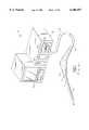
- FIG. 1is a front isometric view of a known medical diagnostic instrument system in accordance with the prior art
- FIG. 2is a perspective view of a video instrument system in accordance with a preferred embodiment of the present invention
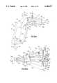
- FIG. 3(a)is a cross sectional view of the instrument body and an attached instrument head used in the system of FIG. 2, according to a preferred embodiment
- FIG. 3(b)is a partial front perspective view of the front face of the instrument body of FIG. 3(a), illustrating one half of a releasable latching mechanism
- FIG. 4(a)is a side-sectional view of an otoscopic instrument head interchangeably used with the instrument body shown in FIG. 3;
- FIG. 4(b)is a rear perspective view of the otoscopic instrument head of FIG. 4(a), emphasizing the remaining portion of the preferred latching mechanism;
- FIG. 4(c)is a partial front perspective view of the otoscopic instrument head of FIGS. 4(a)-4(b), depicting a retained lamp assembly and corresponding electrical contacts;
- FIG. 4(d)is a partial side pictorial view of the otoscopic instrument head of FIGS. 4(a)-4(c), illustrating the respective paths of insufflating air and illumination;
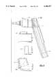
- FIG. 5(a)is a cross-sectional view of a surface microscope head used with the instrument body of FIG. 3(a);
- FIG. 5(b)is a front perspective view of the surface microscope head of FIG. 5(a);
- FIG. 5(c)is a partial front perspective view of the surface microscope head of FIGS. 5(a) and 5(b), illustrating the interconnection between the electrical contacts of a retained lamp assembly and the latching mechanism;
- FIG. 6(a)is a side-sectional view of a general-viewing instrument head interchangeably used with the instrument body of FIG. 3(a);
- FIG. 6(b)is a partial rear perspective view of the general-viewing instrument head of FIG. 6(a);
- FIG. 6(c)is a partial side sectional view of the latching mechanism of the general-viewing instrument head of FIGS. 6(a) and 6(b), as engaged with the instrument body of FIGS. 3(a) and 3(b);
- FIG. 7(a)is a side-sectional view of a magnifying instrument head interchangeably used with the instrument head of FIG. 3(a);
- FIG. 7(b)is a partial front perspective view of the magnifying instrument head of FIG. 7(a), illustrating the interconnection between the latching mechanism and the lamp electrical contacts;
- FIG. 7(c)is a rear perspective view of the magnifying instrument head of FIGS. 7(a) and 7(b);
- FIG. 8is a partial side sectional view of an instrument body according to a second preferred embodiment of the present invention.
- FIG. 9is a partial side sectional view of the instrument body of FIG. 8, including an attached surface microscope head in accordance with a separate embodiment of the present invention.
- FIGS. 10(a) and 10(b)are perspective views of an illumination light pipe used in accordance with the surface microscope head of FIG. 9;
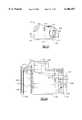
- FIG. 11is a partial side assembly view of an imaging instrument system according to a third embodiment of the present invention.
- FIG. 12is a side sectional view of the assembled imaging instrument of FIG. 11.
- FIG. 13is a side sectional view of a video instrument according to a fourth embodiment of the present invention.
- FIG. 14is a side partial view of a multimedia instrument made in accordance with a preferred embodiment of the present invention.
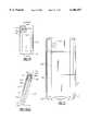
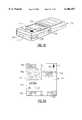
- FIG. 15is a front elevational view of the multimedia instrument of FIG. 14;
- FIG. 16(a)is a side sectional view of the multimedia instrument as taken through line 16--16 of FIG. 15;
- FIG. 16(b)is an enlarged front isometric view of a front interface of the multimedia instrument of FIGS. 14-16(a);
- FIG. 17is a rear elevational view of the multimedia instrument of FIGS. 14-16(a);
- FIG. 18is a side perspective view of the instrument of FIG. 17, with the sliding cover being moved to an open position to allow access to a touch sensitive display;
- FIG. 19is a partial rear view of the instrument of FIGS. 14-18, showing video display and annotation features of the touch sensitive display;
- FIG. 20is a side view of the otoscopic instrument head shown in FIG. 14;
- FIG. 21is a front isometric partially cutaway view (enlarged) of the otoscopic instrument head of FIG. 20;
- FIG. 22is a rear view of the otoscopic instrument head of FIGS. 20 and 21;
- FIG. 23is a sectional view of the otoscopic instrument head of FIGS. 20-22;
- FIG. 24is an enlarged sectional view of the optical system of the otoscopic instrument head of FIGS. 20-23;
- FIG. 25is a front perspective view of the general viewing instrument head illustrated in FIG. 14;
- FIG. 26is an enlarged partially cutaway isometric view of the general viewing instrument head of FIG. 23, rotated approximately 45 degrees;
- FIG. 27is a side view of the surface microscope head of FIG. 26;
- FIG. 28is a cut-away partial rear perspective view of the surface microscope head of FIGS. 26 and 27;
- FIG. 29is a sectional view of the surface microscope head of FIG. 27, as taken through the line 29--29;
- FIG. 30is a side perspective view of the polarizing lens assembly of the instrument head of FIGS. 27-29;
- FIG. 31is a side perspective view of the magnifying instrument head of FIG. 14;
- FIG. 32is an enlarged rear view of the instrument head of FIG. 31;
- FIG. 33is a partially cutaway front isometric view of the instrument head of FIGS. 31 and 32;
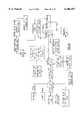
- FIG. 34is a block diagram of a preferred system architecture for a multimedia instrument according to the present invention.
- FIG. 35is a systematic diagram of the instrument of FIG. 14 in connection with a receiving cradle capable of transferring data between the diagnostic instrument and a central data network;
- FIG. 36(a)illustrates respective top and front partial views of a multimedia instrument according to a second embodiment of the present invention
- FIG. 36(b)is a partial front view of an instrument in accordance with a third embodiment of the present invention.
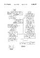
- FIG. 37is a flow chart representative of the prior art for transcription methodology relating to audio medical records
- FIG. 38is a flow chart according to a data management system using the mulitmedia instrument system of FIGS. 14-34;
- FIG. 39is a second flow chart of transcription procedure in accordance with the prior art.
- FIG. 40is a flow chart illustrating the flow of image and audio data in connection with the data management system of FIG. 38;
- FIG. 41is a detailed flow chart of the transcription process using the data management system of FIG. 38;
- FIG. 42is a generalized diagram illustrating the transfer of data between a multimedia instrument, a local computer and a data network.
- FIG. 43is a sample data sheet created using the data management system shown in FIGS. 34, 35 and 38-42.
- the instrument system 10includes a medical diagnostic instrument 14, an endoscope (ie: a video laparoscope) being shown, defined by an elongate instrument body 16 having a distal end 18 and an opposite proximal end 17 attached to a handle section 20.
- An electronic sensor or element(not shown), such as a CCD (charge coupled device), is disposed within the instrument body 16 and receives an optical image of a target of interest through an imaging system, such as a relay lens system (not shown) or other known arrangement, in a conventional manner.
- the electronic sensorincludes support electronics which convert the optical signal into an electrical signal which is transmitted along a sheathed cable 22 depending from the proximal end 24 of the handle section 20.
- a video processing module 28forms the proximal end of the sheathed cable 22, the module containing processing electronics for converting the transmitted electrical signal into a video monitor-ready (PAL, NTSC, etc.) signal.
- the video processing module 28is attached into a receiving cavity 29 of a light/power box 32 containing a high output light source, such as an arc lamp (not shown) or other source of white light.
- a high output light sourcesuch as an arc lamp (not shown) or other source of white light.
- the light from the high-intensity light sourceis transmitted from the light box 32 through an optical fiber bundle (not shown) contained within the sheathed cable 22, and guided into the diagnostic instrument body 16 to the distal end 18 thereof.
- the light/power box 32also serves to furnish power to the diagnostic instrument 14 through electrical connectors, also contained within the sheathed cable 22, the power/light box being operated by a control panel 30.
- a processed video signal of the target of interestis displayed by an interconnected video monitor 34 which is connected to the light/power box 32 to allow viewing, by a physician and patient(s).
- Other peripheral devicessuch as a video printer, a video tape recorder, a PC, etc., can also be substituted into the above described instrument system.
- the above diagnostic instrument system 10introduces a number of discrete components and requires a significant spatial footprint typically restricting the use of the system to a dedicated area, such as a physician's office, an emergency room, etc.
- a dedicated areasuch as a physician's office, an emergency room, etc.
- other types of diagnostic instrumentssuch as otoscopes, colposcopes, and dermatoscopes, among others, are required for performing other types of examinations that are typically done during a patient visit. That is, it is not uncommon that a variety of different examinations, (ear, eye, throat, skin) could be performed in a single family practitioner visit.
- the ability to electronically capture and archive images for each type of examinationwould be desirable, allowing the patient and the physician to both view a target of interest, but as noted above, typically a separate dedicated system is required for each instrument.
- FIG. 2there is provided a diagrammatic view of a medical diagnostic instrument system 40 according to a first preferred embodiment of the present invention including a primary instrument body or housing 42 having a front or distal face 44 and a proximal end 46.
- a plurality of instrument heads 48, 50, 52 and 54are interchangeably and releasably mountable to the front face 44, the details of which will be described in greater detail below.
- the instrument body 42is tethered by known means at the proximal end 46 to one end of an umbilical cable 56, the remaining end of which is attached to an interface box 58.
- the interface box 58acts as a conduit to supply electric power to the described system 40 from a transformer 60 connected to a conventional wall outlet 70, though it is conceivable that other electric power sources, such as batteries and the like, could be alternately utilized.
- a battery powered instrumentis described in a succeeding embodiment of this invention.
- the interface box 58includes a number of attachment ports 62 to enable interconnection to a number of video peripheral devices.
- a video monitor 64, a video printer 66, and a personal computer 68are shown, each of which is capable of receiving a processed video signal from the diagnostic instrument, as is described in greater detail below.
- the interface box 58includes additional ports (not shown), allowing a plurality of instrument bodies 42A, 42B to be similarly interconnected by umbilical cables 56A, 56B. Details relating to the method of interconnection are well known in the field and require no further discussion for purposes of the present invention.
- a conventional wall mount 71is preferably provided for receiving and retaining an instrument body 42 or bodies 42A, 42B when the instrument is not in use.
- the wall mount 71may also be suitably equipped to provide a signal to turn the illumination and video mechanism off upon engagement therewith; that is, to shut the unit off automatically when the instrument is no longer in use.
- the instrument body 42includes a substantially hollow interior 72 defined by a hand-holdable section 74 and an instrument section 76.
- the hand-holdable section 74assumes the shape of a pistol grip, though other convenient shapes or designs can alternately be used.
- Each of the two sections 74, 76are integral, the instrument body 42 having a separable two-part housing 78 which is attached using threaded fasteners 80 through holes 81 provided at either end.
- the interior 72 of the instrument section 76is sized for containing a miniature video camera, such as a charge coupled device (CCD), CMOS, or other electronic sensor 82, having a substrate 84 defining an image plane for receiving an optical signal along a viewing axis 85, extending to the front face 44, FIG. 2, of the instrument body 42.
- a miniature video camerasuch as a charge coupled device (CCD), CMOS, or other electronic sensor 82
- CMOScomplementary metal-sable 82
- a series of transmission lines 88are soldered or otherwise connected to a series of connector pins (not shown) extending from the rear of the electronic sensor 82, by known means, to an integrated circuit board 92 disposed in the hand-holdable portion 74.
- the circuit board 92contains video processing circuitry (not shown) for converting the electrical signal from the electronic sensor 82 into a video signal which is then transmitted from the circuit board along the transmission lines 83 extending through the umbilical cable 56 to the video peripheral devices 64, 66, 68, FIG. 2, through the interface box 58, FIG. 2.
- the umbilical cable 56as partially shown in FIG. 3(a), includes a flexible covering 90 and is sized for also containing additional transmission lines 94 for transmitting electric power from the transformer 60, FIG. 2, to the instrument section 76.
- the instrument body 42also contains a power ON/OFF switch 95 comprising a depressible portion extending through a slot (not shown) in the two-part housing 78, as well as a similarly disposed white balance button 98, the purpose of which will be described below.
- one of the instrument headsin this instance an otoscopic instrument head 48, is shown which is releasably attachable to the front face 44 of the instrument body 42.
- the instrument head 48has an illumination assembly including a supported halogen lamp or other suitable light source, and an imaging system retained therein.
- a major feature of the present inventionrelates to the powering of the illuminating assembly using a latching mechanism described in detail below. Additional details also follow pertaining to features of each interchangeable instrument head 48, 50, 52, 54, as well as the operation of the diagnostic system 40 of this embodiment.
- the front face 44 of the instrument body 42includes a base portion 100 defined by an open ended distally extending section 104 having a circular metal alignment plate 108 mounted therein, the plate having a substantially flat contact surface 110.
- the alignment plate 108also includes a centrally disposed and substantially circular cavity 112 having a defined bottom planar surface 116. As noted, the cavity 112 is substantially circular, with the exception of a pair of diametrically opposed tab sections 120.
- a cylindrical pilot section 124projects distally from the planar surface 116, the section comprising a circular cross section and an open end 128 centrally disposed about a center aperture 132.
- the center aperture 132is centrally disposed on the front face 44 of the instrument body 42 and communicates with the interior of the instrument section 76, FIG. 3(a). Furthermore, the center aperture 132 is aligned with the viewing axis 85, FIG. 3(a).
- the metal alignment plate 108is securely fastened to the base portion 100 by engagement of a pair of threaded fasteners (not shown) into corresponding diametrically opposed holes 136.
- the holes 136are preferably countersunk to ensure the planarity of the contact surface 110.
- a pair of electrical contacts 140 connected to the power transmission lines 83, FIG. 3(a),are provided in a pair of openings 144 provided on the planar recessed surface 116. According to this embodiment, the openings 144 are also diametrically opposed, and are disposed adjacent the tab sections 120.
- the contacts 140are preferably flush with the planar surface 116.
- a pair of stops(not shown) are provided within respective annular slots 148, shown in phantom, extending radially from the tab sections 120, the purpose of which is described below.
- instrument heads 48, 50, 52, and 54are releasably attachable to the front face 44 of the instrument body 42, the description of which is now attended to.
- Each of the above instrument headsinclude an identical latching mechanism for releasable attachment to the front face 44 of the instrument body 42.
- the following discussionspecifically refers to the latch mechanism related to the otoscopic instrument head 48. Similar features are present in the attachment of the remaining instrument heads 50, 52, 54.
- the front facing surface of the instrument and the rear surface of the instrument headsare the interfacing surfaces
- mechanisms embodying the concepts prescribed hereincan be provided using other surfaces thereof.
- the instrument headscould be attached to the top of a suitable instrument body for use (e.g. a side-viewing instrument head, etc).
- the rear or proximal face 152 of the otoscopic instrument head 48includes a ring-shaped latching member 156 having a substantially circular configuration with the exception of a pair of diametrically opposite ear portions 160.
- the latching member 156is disposed within a correspondingly shaped cavity 164 provided in a flat ring 158 which is fixedly secured to the rear face 152 using a plurality of evenly spaced threaded holes 168.
- the threaded holes 168are sized for receiving a corresponding number of threaded fasteners (not shown).
- each of the fastener holes 168extend into an interior wall 170 of the instrument head 48.
- a single pin hole 172similarly extends into the latching member 156 and into the interior wall 170.
- a pin (not shown) inserted into the pin hole 172prevents rotation of the latching member 156.
- the latching member 156is a cylindrical member having a pair of open ends 157 centrally disposed relative to a center opening or aperture 177 communicating with the interior of the instrument head 48.
- a pair of diametrically opposed cylindrical electrical contact elements 192are slidingly attached to the latching member 156 through openings extending therethrough into the interior of the instrument head 48 for allowing axial movement thereof.
- a plastic insulator 200surrounds each the contact element 192, as shown in FIG. 4(a).
- the latching member 156is preferably made from a stainless steel and includes an inner annular shoulder portion 176 disposed within a cavity 180 formed in the interior of the rear face 152.
- An O-ring 184is also disposed within the cavity 180 between the annular shoulder portion 176 and the interior surface of the flat ring 158.
- the latching member 156is intentionally biased rearwardly relative to the rear face 152 by the O-ring 184 to a first axial position. This position is most clearly shown in FIG. 4(a).
- the leaf springs 183each include an engagement portion 188 at one end which is aligned with the inwardly extending end of a contact member 192 so as to supply a bearing force thereupon.
- the rear side 152 of the instrument head 48is brought into engagement with the front face 44 of the instrument body 42, FIG. 3(b).
- the latching member 156is aligned with the cavity 112, and more specifically the ear portions 160 are aligned with the tab portions 120.
- the cavity 112, including the tab portions 120closely match the profile or contour of the latching member 156.
- the engagement of the cylindrical pilot portion 124causes the latching member 156 to be directed forwardly toward the interior of the instrument head 48 against the bias of the O-ring 184, ensuring significant contact between the flat ring 158 and the contact surface 110.
- the described rotational movementcauses the contact members 192 to align with and engage with the corresponding electrical contacts 140 in the instrument body 42, thereby supplying electric power to the supported lamp assembly 101.
- a userreverses the above procedure by grasping and rotating the instrument head in the opposite (counterclockwise) direction until the ear portions 160 are aligned with the tab portions 120 in the instrument body 42.
- the instrument head 48is then pulled axially away from the front face 44 of the instrument body 42, causing the latching member 156, as biased by the O-ring 184, to be moved back into the initial axial position.
- each of the remaining instrument heads 50, 52, and 54include an identical latching mechanism for releasable engagement with the front face 44 of the instrument body 42. An actual engagement therebetween is also illustrated in FIG. 6(c).
- the instant instrument head 42is defined by a substantially frusto-conical configuration including a rear housing portion 202, an intermediate housing portion 204, and an front housing or insertion portion 206 distally arranged therefrom.
- the insertion portion 206includes overlapping and conically shaped inner and outer tip housings, 210, 214, each having a respective distal tip opening 218, 222.
- a safety speculum 226 made from a plastic material and having a distal tip opening 228is mounted onto the conical periphery of the outer tip housing 214, also in overlapping relation thereto.
- a linear lens tube 230is retained within the interior of the inner tip housing 210 extending rearwardly from the tip opening 218.
- a series of objective lens assemblies 234are retained within each of the lens tubes 230.
- the illumination assembly 101includes a miniature halogen lamp 238 which is disposed within the rear housing portion 202 and press-fitted within a spring-metal receptacle 242 placed in a spaced enclosure 244 formed by a pair of supporting plates 246 mounted to a rear wall 248.
- the spring metal receptacle 242forms a pocket sized for retaining the lamp 238 from one of a pair of flat sections 252, which are mounted to the exterior of the supporting plates 246.
- the remaining flat spring-metal section 254includes a curved section 256 which is disposed behind the lamp 238 and into engagement with the lamp contacts 258.
- Each of the flat spring metal sections 252, 254support the leaf springs 183 such that when the contacts 192 engage the contacts 140 in the instrument body 42, FIG. 3(a), that the electrical circuit is completed, allowing the lamp 238 to be powered.
- light from the halogen lamp 238is directed to one end of a bundle of optical fibers 262 (partially shown in FIG. 4(a)) which are fanned out into an annular space 264 formed between the lens tube 230 and the interior wall of the inner tip housing 210.
- the bundle of fibers 262terminate at the distal tip opening 218 of the inner tip housing 210 as a polished light emitting end 266.
- an insufflation port 250is provided in the intermediate housing portion 204 and sized to receive a fitting 268, shown only in FIGS. 3(a) and 4(a).
- the insufflation port 250defines one end of a passageway extending into the interior of the insertion section 206.
- the fitting 268allows a known depressible pneumatic bulb (not shown) to be connected thereto for directing air (or creating a vacuum) through the path 270 which is defined through an opening in an interior wall 272 into an annular space 260 between the inner and outer tip housings 210, 214.
- the airthen passes out the distal tip opening 222 of the outer tip housing 214 and into another annular space 274 defined between the inner tip housing 210 and the interior of the safety speculum 226.
- the directed airexits through the distal tip opening 228 of the safety speculum 226.
- a rear wall 278seals the assembly, along with the mounted safety speculum 226 from air leakage other than through the distal tip opening 228, as shown in FIG. 4(d).
- the safety speculum 226is releasably attached to the outer tip housing 214 using a bayonet attachment as described in commonly owned U.S. Pat. No. 4,380,998 issued to Kieffer, et al, the entire contents of which are herein incorporated by reference.
- the otoscopic instrument head 48is attached as previously described and as shown in FIG. 3(a).
- the described latching mechanismallows the instrument head 48 to be locked into engagement with the front side 44 of the instrument body 42.
- this engagementallows the proper electrical interconnection to power the lamp assembly 101 which directs light through the optical fiber bundle 262 to the distal tip opening of the insertion portion 206.
- insufflation capabilityis provided through the port 250 to allow stimulation of the tympanic membrane.
- the target of interest(the interior of the ear canal) is viewed by the objective lens assembly 234 through the aligned tip opening 226, 218 which then projects the optical image along the viewing axis 85, FIG. 3(a), focusing the image onto the electronic sensor 82, FIG. 3(a).
- an instrument head of the above or similar designcould be used in cavities having narrow or shaped openings in-addition to the ear canal.
- a surface microscope head 50includes an elongated housing 280 having a hollow interior 288 and respective proximal and distal ends 284, 296.
- the housing 280has a substantially frusto-conical configuration with the proximal end 284 being wider than the distal end 296 to provide adequate space allocation for an illumination assembly 282 disposed therein.
- the proximal end 284 of the instrument head 50is defined by a cylindrical base portion 290 having a cavity 291 sized for retaining a shoulder portion 177 of a latching member 156.
- the cavity 291is formed between a flat ring 158 mounted by threaded fasteners (not shown) through countersunk holes 168 to an interior wall 302.
- the remainder of the latching member 156extends through an opening 164, FIG. 4(b), on the flat ring 158, and is biased into a first axial position by a pair of leaf springs 304, 306 mounted to the inside surface of the interior wall 302 and engaged into biasing contact with a pair of contact members 192, only one being shown in FIG.
- latching member 156is identical to that previously described which releasably engages the front face 44, FIG. 3(a), of the instrument body 42, FIG. 3(a). Therefore, no further discussion is required except as needed.
- a releasably attachable lens holder 292is disposed at the distal end 296 thereof
- the lens holder 292accommodates a viewing window 300 having a measuring reticle (not shown) for providing a frame of reference or means of measuring a target of interest.
- the viewing window 300provides a field of view of approximately 15 mm, and is releasably attachable to allow cleaning and/or sterilization.
- the viewing window 300 according to this embodimentis made from a plate glass, though any optical grade material including light plastics such as acrylic, or polycarbonate are suitable.
- the illumination assembly 282includes a light source, such as a miniature halogen lamp 298, which is retained within a spaced enclosure 305 formed by a pair of parallel supporting plates 310 extending from the interior of the wall 302.
- a light sourcesuch as a miniature halogen lamp 298, which is retained within a spaced enclosure 305 formed by a pair of parallel supporting plates 310 extending from the interior of the wall 302.
- other suitable light sourcessuch as low-power surface-mounted or bulb-type white LEDs, can also be substituted.
- the spaced enclosure 305further includes a spring metal receptacle 314 into which the lamp 298 is press-fitted, the receptacle being formed from one of a pair of leaf springs 304 having a substantially flat portion attached to the interior of the wall 302.
- the remaining leaf spring 306includes a flat extending portion 320 for contacting the rear electrical contacts (not shown) of the halogen lamp 298 when fitted into the spaced enclosure 305.
- a first polarizer 308is provided at the light emitting end of the lamp 298 and attached to the corresponding end of the supporting plates 310.
- the first polarizer 308is angled relative to the axis formed between the viewing window 300 and a lens assembly 316 including a plano lens 318, an aperture plate 322, and an objective lens 326 respectively disposed within the interior of the base portion 290.
- a second polarizer 312is also provided between the viewing window 300 and the lens assembly 316, to assist in minimizing glare presented by the illumination assembly 282.
- the polarizer 308, 312also combine to minimize specular glare from the target (e.g. skin) surface.
- the instrument head 50is mounted in the previously described manner such that the latching member 156 inwardly deflects when engaged with the front face 44, FIG. 3(a), of the instrument body 42. This deflection causes the cylindrical contact members 192 to bear against respective engagement portions 330 of the leaf springs 304, 306, as illustrated in FIGS. 5(a) and 5(c). Subsequent twisting of the instrument head 50 as described above, also aligns the contacts 192 with the corresponding contacts 140, FIG. 3(b), provided in the instrument body 42, FIG. 3(b), and completes an electrical connection causing the lamp 298 to illuminate upon locking of the instrument head 50 in place.
- the illumination assembly 282, and particularly the first polarizer lens 308, being angled relative to the viewing axis 85causes light to indirectly strike the viewing window 300 in order to minimize reflective glare from the inside surface thereof, and to prevent an image of the illuminating assembly to be reflected optically through the lens assembly 316.
- the lens assembly 316, including the second polarizer 312, and the viewing window 300are each aligned along the viewing axis 85, FIG. 3(a), to allow a focused optical image to be transmitted to the electronic sensor 82, FIG. 3(a).
- the lens assembly 316allows focusing of an optical image of the target (a wart, lesion, or other skin disorder) when the viewing window 300 is placed in direct contact therewith.
- the general viewing instrument head 52includes a cylindrical base section 340 similar in construction to the dermatological instrument head 50 previously described.
- An adjustable lens assembly 344is securely mounted within a lens holder 354 which is threaded or otherwise attached through an opening 352 provided in a distal end 348 thereof.
- the adjustable lens assembly 344includes at least one objective lens (not shown) and an aperture plate (not shown), wherein the objective lens has sufficient power to provide an enhanced field of view.
- the lens assembly 344is movable along a defined axis 362 and allows an optical image to be focused onto the electronic sensor 82, FIG. 3(a).
- the optical axis 362is aligned with viewing axis 85, as shown in FIG. 6(c).
- the instant instrument head 52includes a latching member 156 as previously described for releasably engaging the front face 44, FIG. 2, of the instrument body 42, as shown in FIG. 6(b). Because an illumination assembly is not present, however, the described instrument head can have a compact construction.
- the magnifying instrument head 54is defined by a cylindrical housing 380 including an integral depending portion 384 used to retain an illumination assembly 385.
- the illumination assembly 385includes a halogen lamp 388, or as noted above, another suitable light source, and a reflector 392 which are retained within a pocket 387 formed by a triad of spring fingers 396 extending from a rear wall 389, as most clearly shown in FIG. 7(b).
- the halogen lamp 388includes a rear electrical contact 400 which engages a sheet metal plate (not shown) when the lamp is press-fitted into the spring fingers 396.
- a set of wires 402extend from the metal plate and the spring fingers 396 to respective leaf springs 404 mounted at one end to a rear interior wall 406 of the housing 380.
- the remaining end 415 of the leaf springs 404is cantilevered for movement and is aligned with the ends of cylindrical contact members 192 passing through the latching member 156 and the rear interior wall 406.
- the latching member 156is identical to that described above. To avoid redundancy, a recitation of these features, shown in FIGS. 7(a)-7(c), is not repeated. Therefore, when the latching member 156 is engaged, the electrical connection is completed and the lamp 388 is illuminated.
- the housing 380also includes an adjustable lens assembly 408 defined by a mushroom-shaped housing 412 having a necked portion 416 which is fitted into an opening 420 in the front side of the housing. At least one objective lens assembly 425 and an adjacent aperture plate (not shown) are contained therein.
- the lens assembly 408, according to this embodiment,is received within the opening 420 and is rotatably and axially movable therein to permit focal adjustment.
- a shoulder portion 430having a width dimension which is wider than the opening in the front side of the housing 380 provides an adjustment limit.
- the depending portion 384 of the housing 380is built in two pieces. Removal of the rear wall 389 allows the lamp 388 to be removed for replacement as needed. Finally, the lamp 388 is oriented such that the defined illumination axis 424 is angled relative to the viewing axis 85.
- FIGS. 8-10(b)A second embodiment of a video diagnostic instrument system according to the present invention is herein described with reference to FIGS. 8-10(b). Similar parts are herein labeled with the same reference numerals for the sake of convenience.
- an instrument base unit 460having a hollow interior 464 and within which an imaging assembly 470 and an illumination assembly 498 are each provided.
- the imaging assembly 470includes a CCD or other electronic sensor 82 having an image plane or substrate 84 which is aligned with a viewing opening 468 of the base unit 460, thereby defining a viewing axis 85.
- a video processing board 472having circuitry for converting an electronic signal from the electronic sensor 82 to a monitor-ready video signal is also disposed within the interior 464 of the base unit 460 and is interconnected by transmission lines (not shown) through an umbilical cable 56 partially shown).
- the illumination assembly 498includes a halogen lamp 502 positioned within a reflector 506, the lamp having electrical contacts (not shown) which are interconnected to the transmission in the umbilical cable 56.
- a plurality of instrument headscan be releasably mounted to the front face of the instrument base unit 460, in a manner similar to that described above.
- an exemplary instrument headis shown in FIG. 9, which is a surface microscope head 520 similar to that described as 50 above, having a housing 522, including an engagement or locking member 524 projecting from the rear side 528 for attachment within a defined cavity 530 of the distal face of the instrument base unit 460.
- the instrument head housing 522includes a viewing window 526 mounted in a releasably attachable circular lens holder 527 which is mounted on the distal end 532 of the housing oppositely disposed from the locking member 524.
- the housing 522further includes an expanded interior 533 sized for retaining a light pipe 534 for transmitting light from the illumination assembly 498 to the viewing window 526.
- the light pipe 534is made from a transparent (light-transmissive) material, such as acrylic or polycarbonate, including a light receiving end 542 which is positioned in alignment with the light emitting end 500 of the illumination assembly 498, which as noted earlier, is disposed above the imaging assembly 470.
- the light receiving end 542is part of a cylindrical light emitting portion 538 which is curved to allow the light pipe 534 to extend into the expanded portion of the interior 533.
- the pipe 534includes a cylindrical light emitting portion 538 at the remaining end having a through opening 546 to enable an optical image from the viewing window 526 to be transmitted along the viewing axis 85 without interference.
- light from the illumination assembly 498is transmitted through the length of the light pipe 534 where the light is transmitted in a circular area through the viewing window 526 from the cylindrical light emitting portion 538.
- the location of the electronic imager 82 in the described systemis not limited to the interior of the instrument body. Referring to FIGS. 11 and 12, a diagnostic instrument system in accordance with a third embodiment of the present invention is herein described.
- An instrument body 560includes a hand-holdable portion 564 shaped similarly like a pistol grip which includes a hollow interior 568 sized to retain a number of components.
- the body 560is a two-part housing connected by fasteners inserted through spaced holes 640.
- a number of depressible buttons and/or switchesare included on the exterior of the body 560 to control a number of functions including an ON/OFF power switch 572, a white balance switch 576, and an electronic zoom control switch (not shown).
- At least one instrument head 584is mountable to the front face 588 of the instrument body 560, the instrument head including an electronic imager assembly 590 and an illumination assembly 592 disposed within a substantially hollow interior 593.
- the imager assembly 590includes an electronic sensor 82 disposed adjacent to a rear wall 600 and includes a number of spring-loaded contacts 608 on the exterior of the rear wall 600, which can be subsequently brought into engagement with corresponding contacts 604 provided on the front face surface 588 of the instrument body 560.
- the illumination assembly 592includes a halogen lamp 612 positioned above the imager assembly.
- An opening 638 in the rear wall 600allows the lamp to be accessed for replacement, while the imager assembly 590 is accessible by means of a removable cover 639.
- the engagement interface between the instrument head 584 and the instrument body 560is structurally different than the latching mechanisms previously described.
- the rear wall 600 of the instrument head 584includes a peripheral slot 628 covering at least three sides of the periphery for engaging a correspondingly sized annular shoulder 630 provided in the front face 588 of the instrument body 560.
- the instrument head 588is fitted by sliding the head onto the body 560 in the direction of arrow 634, as shown in FIG. 11.
- the instrument 1100includes a body section 1104 and an instrument head 1108 which is releasably attachable to a distal face 1112 thereof.
- the instrument head 1108includes a housing 1116 having a distal receptacle 1120 sized for accommodating a lens assembly 1124 having a series of linearly arranged optical elements disposed along an optical axis 1128 in an adjustable lens cell 1126.
- An electronic imager 1132such as a miniature CCD or CMOS vide camera, is attached to an interior surface 1140 of a rear wall 1136 of the instrument head 1108.
- the imager 1132includes a light receiving surface (not shown) which is aligned with the optical axis 1128 to receive any focused image of a target of interest from the adjustable lens cell 1126.
- a polarizer element 1 144is disposed between the electronic imager 1132 and the receptacle 1120.
- the polarizer element 1144is preferably attached to a slide mechanism 1148 externally connected to the housing 1116 through a slot 1152, allowing selective positioning of the polarizer element relative to the optical axis 1128.
- An adjustable lamp assembly 1156includes a low-power miniature halogen lamp or other suitable light source to an external portion of the instrument head housing 1116.
- the lamp assembly 1156is pivotally attached to the housing 1116, the housing having a series of circumferentially disposed detents 1160 for accommodating toothed sections 1164 of the lamp assembly 1156 so as to orient the lamp until the illumination axis 1157 is aligned with and intersects the optical axis 1128.
- Other suitable automatic or manual assembly mechanisms(not shown) for rotating or otherwise shifting the location of the lamp assembly 1156 can easily be imagined.
- the body section 1104 of the instrument 1100includes a handle configuration having an interior sized for accommodating a number of components.
- the interior 1170includes a battery compartment 1174 for at least one contained rechargeable battery 1178.
- An RF (radio frequency) antenna 1180is attached by conventional means and extends from an upper part of the body section 1104. Electrical connectors 1182 extending from the RF antenna 1180 are connected to a conventional RF circuit board 1184. Another set of electrical connectors 1188 extend from opposite sides of the battery compartment 1174 in alignment with the terminals of the battery 1178 to a power modifying printed circuit board 1194 disposed adjacent the distal face 1112 of the instrument head and having appropriate regulators and drivers for setting the voltage and wattage for powering the imager 1132 and the adjustable lamp assembly 1156 of the instrument head 1108.
- a series of spring loaded contacts 1200extend from the front of the power modifying printed circuit board 1194 for engaging female contacts 1202 located on the exterior side of the rear wall 1136 of the instrument head 1108.
- the circuit board 1194is interconnected by known means to a set of switches located on the exterior of the body section 1104 of the instrument 1100. More particularly, these switches include an ON/OFF power switch 1216, an electronic zoom switch 1218, and a white balance switch 1220, wherein the power modifying circuit board 1194 is connected in a known manner order to support the above switches.
- the lens cell 1126is adjustable via a threaded portion 1212 which engages a threaded opening 1214 of the lens assembly 1124.
- the distal receptacle 1120includes a groove 1122 for accommodating an O-ring 1208 on the lens assembly 1124 used to seal the lens assembly into position.
- engagement of the corresponding contacts 1200, 1202 during attachment of the instrument head 1108 to the distal face 1112 of the body section 1104powers the adjustable lamp assembly 1156 and the electronic imager 1132 by connection with the power modifying printed circuit board 1194, as powered by the battery 1178.
- Selective depression of the power ON/OFF switch 1216can also be used to control the lamp assembly 1156 and imager 1132 after the instrument head 1108 has been attached.
- the latching mechanism used to retain the instrument head 1108is similar to that described in FIG. 12 in which the rear wall 1136 of the instrument head 1108 includes a peripheral slot 1222 for engaging a corresponding annular shoulder 1226 of the distal face 1112 of the body section 1104, though other means could similarly be employed.
- the output of the electronic imager 1132can be transmitted using the RF circuitry and antenna 1180 to a video processor, video printer or other peripheral device (not shown) having suitable means for receiving and decoding the RF signal and obviating the need for cabling.
- a charger port 1224extends from the bottom of the body section 1104 to allow recharging of the battery 1178 without having to remove the battery from the compartment 1174.
- a diagnostic instrument system 730comprises a compact diagnostic instrument 732 including a housing or body 734 having a front interface 736 with means for allowing selective releasable attachment thereto of a plurality of instrument heads.
- the instrument headsinclude a general purpose instrument head 738, a dermatological instrument head 740, a high magnification instrument head 742, and an otological instrument head 746.
- Other instrument headssuch for ophthalmoscopes employing optical systems such as described in commonly assigned U.S. Pat. Nos. 4,526,449 and 4,998,818, for example, incorporated by reference herein, can also be utilized.
- each of the instrument heads 738, 740, 742, 746 and the attachment of each to the diagnostic instrument 732are described in greater detail below. In passing, however, it should be noted that the instrument heads described in the first embodiment could be substituted for those about to be described and vice versa. Still further, other suitable heads for the same or other purposes, e.g. ophthalmoscopic could be envisioned.
- the diagnostic instrument 732 for purposes of the described system 730, FIG. 14,is a compact digital camera having a defined interior 748.
- the interior 748is appropriately sized to retain a plurality of components including an electronic imaging element 750, such as a charge coupled device (CCD), disposed adjacent a window 752 or clear covering at the front interface 736.
- an electronic imaging element 750such as a charge coupled device (CCD)
- CCDcharge coupled device
- the digital camera used in the described embodimentis a "COOLPIX 300" sold by the Nikon Corporation, though it will be apparent that other known compact digital cameras having similar or other features can be similarly configured for use in the described diagnostic instrument system.
- a controllersuch as a microprocessor with sufficient memory and programmable logic is contained within the interior of the instrument housing 734 and is interconnected to the retained components, including an integral touch-sensitive TFT liquid crystal display (LED) 754, provided at the rear side 756 of the instrument housing 734.
- LEDliquid crystal display
- an eyepiece (Kopin) type of displaycould be used.
- the processed digital video signalis outputted to the display 754 by the microprocessor for viewing by the user.
- the rear side 756 of the instrument housing 764is angled, as shown in FIG.
- an angle, represented in FIG. 16 as --A--, of approximately 15 degreesis suitable.
- the programmable logic and internal memory of the microprocessorallows various forms of data to be captured and stored in conjunction with image (video) information.
- An internal condenser microphone 764 disposed on the top exterior of the instrument housing 734allows audio information to be captured and stored selectively into the memory of the microcontroller (not shown), while an integral speaker 766 disposed on the rear side 756 of the housing allows playback of the stored audio information in conjunction with a stored video image.
- a plurality of control switches located on the exterior of the instrument housing 734includes a POWER ON/OFF switch 768, as well as a RECORD/PLAYBACK switch 770 controlling the audio recording and playback features of the camera.
- a series of indicating lampsare also provided, more specifically a power lamp 772, a ready lamp 773, and a recording lamp 774.
- the described digital camera used as the diagnostic instrument 732includes other salient and specific features relating to image capture, such as programmed auto-exposure control, including an electronic single-frame shutter and automatic gain control.
- programmed auto-exposure controlincluding an electronic single-frame shutter and automatic gain control.
- the specific teachings of these featuresdo not specifically form a part of the present invention. Therefore, no further discussion is required.
- Activation of the diagnostic instrument 732 using POWER ON switch 768activates the imager and processing circuitry so as to allow a real time video image to be viewed on the TFT display 754.
- the viewed imagecan be selectively captured using a shutter release button provided on the instrument housing 734 (not shown), causing the image to be stored into the internal memory of the controller.
- Activation of the switch 770allows the microphone 764 to be enabled to allow audio data to be captured corresponding to the video image which is being currently displayed.
- the cameraincludes a MENU feature controlled by the programmable logic of the controller which allows the length of the sound clip to be controlled. Alternately, other modes are provided for recording sound without use of the video capture mechanisms, if desired. Audio data is stored in a WAV format, though other formats with varying degrees of compression may also be used. In the present embodiment, approximately 17 minutes of sound data memory are provided though this quantity can easily be varied.
- the TFT display 754includes a main window 776 and a plurality of selectable keys disposed about the periphery thereof, including a key for accessing a main menu 778, an ENTER key 780, a CANCEL key 782, and a DELETE key 784. Keys 786 are also provided to allow scrolling in either vertical direction.
- the main window 776can be selectively divided into separate image fields for allowing multiple stored digital images to be displayed simultaneously, and to allow annotation relating to a displayed image(s). Exemplary image fields 788 and 790 and an annotation field 792 are shown in FIG. 19, though preferably the microprocessor allows literally any number of separate fields to be made available.
- a plurality of miniature captured imagescan be displayed in a sequential manner as a slide show presentation on the main window 776.
- a stylus penselectively allows notes to be added in the illustrated annotation field 792.
- the notesare also stored into the internal memory of the instrument 432.
- the programmable logic of the controller of the described instrument 732also includes an internal calendar, including a date and time stamp which automatically provides an entry which is stored with each corresponding video and/or audio image captured by the camera.
- the multimedia instrumentcould conceivably link forms of data input selectively or not at all. For example, video may not be required for certain applications which may require only annotation and audio data, etc.
- Image data in internal memoryare stored in the presently described instrument using JPEG compression to reduce the amount of memory they consume.
- Image qualitycan be enhanced by adjusting of a menu setting in order to produce either high quality photographs or normal (compressed) photographs which increases the compression ratio and reduces the amount of memory needed to store each photograph.
- the high quality modeallows 66 images to be stored using a compression ratio of 10:1 and 132 photographs to be stored using a compression of 20:1 in the normal mode.
- the instrument housing 734includes a compartment 794, FIG. 17, accessible from the rear side 756 thereof for retaining a set of rechargeable batteries (not shown) for powering the instrument 732.
- a separate adapter cordcan supply power from a suitable AC outlet (not shown).
- the instrument 732further includes a serial port (not shown) and an SCSI port (also not shown in this embodiment) allows selective interconnection to a computer (not shown) or to a docking station or cradle 796, FIG. 34, which is similarly linked to a PC or PC network, according to a preferred embodiment described in greater detail below.
- a serial portnot shown
- SCSI portalso not shown in this embodiment
- the stored audio and video datacan also be transmitted to a video printer, or other suitable peripheral device(s) (not shown).
- the front interface 736 of the herein referred to multimedia diagnostic instrument 732provides releasable but locking engagement with latching members provided on the rear side of each of the instrument heads 738, 740, 742, 746, FIG. 14. Furthermore, engagement also allows electrical contact to be made with illumination sources (if any) provided in the attached instrument head of choice, without interfering with the optical path to the electronic imaging element 750. Attachment of an instrument head of choice using the described latching mechanism also aligns the optical components of the instrument head with the instrument viewing axis 753.
- the front interface 736includes an open-ended distally extending section 798 having a centrally disposed and substantially circular cavity 800 with a defined planar mounting surface 802.
- the cavity 800is substantially circular, with the exception of a pair of diametrically opposed tab sections 804.
- a cylindrical pilot section 806projects distally from the planar surface 802, the section comprising a circular cross section and an open end 808 centrally disposed about an aperture 810 which directly communicates with the interior 748, FIG. 16(a), of the diagnostic instrument 732.
- the aperture 810is coaxial with the viewing axis 753, FIG. 16(a), and extends directly into the instrument 732 to the imaging substrate (light receiving surface) of the electronic imaging element 750, FIG. 16(a), as supported within the housing 734, FIG. 16(a).
- a lens elementcould be supplied within the pilot section and aligned with the imaging element 750 in lieu of or in combination with any of the instrument heads. That is to say, a general or other optical system can be alternately supplied in the instrument interface.
- a pair of stops 814(only one being shown in FIG. 16(b)) is provided within respective annular slots 816, each extending radially from one side of each tab section 804.
- the front interface 736engages the rear or proximal face of a corresponding instrument head of choice.
- the following descriptionrelates to the otoscopic instrument head 746, though each instrument head includes similar features for releasable attachment to the diagnostic instrument 732.
- the otoscopic instrument head 746 of this embodimentincludes a latching member 818 similar to that described in FIGS. 4(a)-4(d) above, the member having a rounded configuration, with the exception of a pair of diametrically opposite ear portions 820 and a pair of flat edges 822.
- the latching member 818is disposed within a correspondingly shaped cavity 824 provided in a flat ring 826 fixedly secured to the rear face of the instrument head 746 by known means.
- the latching member 818is a cylindrical member having a pair of open ends centrally disposed relative to a center opening or aperture 828 communicating with the interior of the instrument head 746.
- a pair of diametrically opposed cylindrical electrical contact elements 830are slidingly attached to the latching member 818 for axial movement thereof adjacent the ear portions 820 through openings extending into the interior of the instrument head 746.
- the contact elements 830are made from metal, though other materials may be substituted.
- the latching member 818is made from plastic (although other non conducting materials can be used), and includes an inner annular shoulder (not shown) disposed within a cavity formed in the interior of the rear face thereof.
- the latching member 818is intentionally biased rearwardly of the flat ring 826 by a pair of internal spring fingers 827 to a first or home axial position.
- a pair of contact springs 834are fixedly attached to the interior facing side 836 of a rear support 839 and includes a depending spring end portion aligned with the inwardly extending end of a contact member 830 so as to supply a bearing force thereupon.
- the rear support 839 of the otoscopic instrument head 746is brought into engagement with the front interface 736 of the instrument body 734.
- the latching member 818is aligned with the cavity 800, and more specifically the ear portions 820 are aligned with the tab portions 804.
- the cavity 800, including the tab portions 804closely match the profile or contour of the latching member 818.
- the engagement of the cylindrical pilot portion 806causes the latching member 818 to be directed forwardly toward the interior of the instrument head 746 against the bias of the internal spring fingers 827.
- the described rotational movementcauses the contact members 830 to align with and engage with the corresponding electrical contacts 812 in the interface 736, thereby supplying electric power to a supported lamp assembly 840, as described below.
- a userreverses the above procedure by grasping and rotating the instrument head 746 in the opposite (counterclockwise) direction until the ear portions 820 are aligned with the tab portions 804 in the interface 736.
- the instrument head 746is then pulled axially away from the interface 736, causing the latching member 818, as biased by the internal spring fingers 827, to be moved back into the initial axial position.
- each of the instrument headsare similarly attached and detached from the front interface 736 of the instrument 732.
- Other salient features of each of the instrument heads used in the present embodimentwill now be described.
- the otoscopic instrument head 746 of this specific embodimentincludes a substantially cylindrically shaped rear or proximal housing portion 839, an intermediate portion 842, and a frusto-conical front or distal insertion portion 847.
- the distal insertion portion 847includes an interior which includes overlapping and conically shaped inner and outer tip housings, 848, 850, each having a respective distal tip opening 852, 854.
- the inner tip housing 848extends distally from the tip opening 854 of the outer tip housing 850.
- a hollow safety speculum 846made from a plastic material and having a distal tip opening 906, is mounted onto the conical periphery of the front insertion portion 847, also in overlapping relation thereto.
- Each of the tip openings 850, 848, 906are coaxial with one another along a defined optical axis 856, the tip openings of the mounted speculum 846 and the front insertion portion 847 being slightly displaced from the tip opening 852 of the inner tip housing 848.
- the optical system of the otoscopic instrument head 746is comprised of a series of axially interconnected lens tubes 858, 860, 862 arranged within the interior of the instrument head 746 along an optical axis 856.
- a negative lens element 864is disposed in a first lens tube 858 adjacent the distal opening 852 of the inner tip housing 848, FIG. 23.
- a plano glass section 866is disposed directly in front of the negative lens 864.
- the interior wall of the first lens tube 858defines a shoulder 868 for supporting and positioning the two optical elements 864, 866.
- the proximal end 870 of the first lens tube 856is wider than that of the remainder of the tube and is sized for receiving the distal end 872 of the attached second lens tube 860.
- An aperture plate 874 and a second lens element 876are retained within the widened proximal end 870 of the first lens tube 858 prior to the distal end 872 of the second lens tube 860.
- the second lens element 876is a positive lens of sufficient power.
- a proximal end of the second lens tube 860is retained within a cavity 878 of the distal end 880 of a third lens tube 862, wherein a third lens element 882 is attached at the proximal end of the second lens tube 860.
- the third lens element 882is a doublet containing a concave and convex lens of an appropriate size.
- a fourth singlet lens element 884is disposed in a cavity 886 at approximately the midpoint of the length of the third lens tube 862.
- an optical signalis channeled through the above disposed lens elements and is ultimately focused at the imaging substrate of the electronic sensor of the diagnostic instrument upon assembly. It should be readily evident that the fourth lens element 884 could alternately be disposed within the pilot section 806, FIG. 16(b), of the instrument 732.
- the optical axis 856 of the otoscopic instrument head 746is coaxial with the viewing axis 753, FIG. 16(a), of the instrument 732, each of the above described lens elements being spaced to allow the optical signal to be focused onto the imaging substrate (not shown) of the electronic imaging element 750.
- the otoscopic instrument head 746includes a miniature halogen lamp 888 disposed conveniently within the rear housing portion 839 and press-fitted within a spring-metal receptacle 890.
- the receptacle 890is defined by a spaced enclosure 892 which is preferably formed by a pair of metal supporting ribs 894, 896 mounted to the interior side of a rear support 898.
- the spring metal receptacle 890forms a pocket sized for retaining the halogen lamp 888, which is preferably angled relative to the optical axis 856.
- light from the halogen lamp 888is directed to one end of a bundle 902 of optical fibers.
- the bundle of fibers 902are fanned out into an annular space 904 formed between the exterior of the lens tubes 858, 860, 862 of the optical system and the interior wall of the inner tip housing 848 so as not to interfere with the transmission of optical data.
- the bundle of fibers 902terminate at the distal tip opening 852 as a polished light emitting end.
- the safety speculum 846is preferably attached in a releasable manner to the exterior of the front insertion portion 847 using a bayonet attachment as described in commonly owned U.S. Pat. No. 4,380,998 issued to Kieffer, et al, the entire contents of which are herein incorporated by reference.
- the previously described latching mechanismallows the instrument head 746 to be locked into engagement with the front interface 736 of the instrument body 734. This engagement allows a proper electrical interconnection to power the lamp 888 which directs light through the optical fiber bundle 902 to the distal tip opening 906 of the insertion portion 846.
- insufflation capabilitycan be provided through a separate port (not shown) to allow stimulation of the tympanic membrane.
- the target of interest(the interior of the ear canal) is viewed through the aligned tip openings, allowing an optical image along the aligned axes 856,753.
- the lens elements of the optical systemare preferably spaced so as to focus the image directly onto the electronic imaging element 750.
- the general purpose or general-viewing instrument head 738includes a cylindrical housing 908 having a rear plate 910 and a defined hollow interior.
- An adjustable lens assembly 912is securely mounted within a lens holder which is threaded or otherwise attached through an opening provided in a distal end 914 thereof.
- the adjustable lens assembly 912includes at least one objective lens and an aperture plate of sufficient size to provide an enhanced field of view for the diagnostic instrument 732 when assembled thereto.
- a field of view of approximately 40 degreesis provided, but this parameter can be easily varied depending on the application.
- the lens assembly 912 of the present embodimentis movable along a defined axis 916 so as to focus at a wide range of distances, allowing a formed optical image to be focused onto the electronic imaging element 750, FIG. 15, while varying the object distance.
- the instrument head 738is attached to the front interface 736 of the instrument 732, in the manner previously described above.
- the latching member 918includes a pair of non-electrical contact members 922 extending through the rear plate 910.
- Each contact member 922includes an interior end for separately engaging a pair of flat springs 924 fixedly attached to the interior side of the rear plate 910.
- the springs 924provide a bias for engaging and locking the instrument head 738 in place with the front interface 736 of the instrument 732.
- the optical pathproceeds in an uninterrupted manner through the interior of the instrument head 738 and the opening defined in the latching member 918, which is focused at the electronic imaging element 750, FIG. 15.
- the surface microscope head 740 of the instant embodimentincludes a two-piece construction comprising a cylindrical housing shell 930 having a hollow interior 932 with open distal and proximal ends 934, 936.
- a second section 938is fitted into the interior 932 of the housing 930.
- the second section 938includes a base portion 940 and a curved side wall 942 which is sized to fit within the interior 932 of the housing 930, the curved side wall being fitted within an axial slot 944.
- a protruding portion 946 of the side wall 942 adjacent the distal end 934 of the instrument head 740is used for retaining a miniature halogen lamp 948.
- the base portion 940includes a cavity 950 sized for retaining a latching member 952.
- the latching member 952operates nearly identically in principle to those previously described above.
- the miniature halogen lamp 948is retained in a pocket 949 formed by a spring metal receptacle 956 located within the protruding portion 946 of the side wall 942.
- a spring metal receptacle 956located within the protruding portion 946 of the side wall 942.
- the receptacle 956is defined by one of a pair of contacting plates 958, 960.
- the first plate 958as shown in FIG. 28, forms a spring loaded sleeve for the miniature lamp 948 while the second plate 960 includes a flat portion 962 in contact with the rear portion of the lamp and the electrical contacts (not shown) thereof.
- Each of the contacting plates 958, 960is manufactured from a spring metal extending in parallel configurations along the interior side or wall 956 of the rear portion 940. A portion of each plate 958, 960 is fixedly attached with a depending spring end 963 of each being cantilevered into biasing contact with axially movable contact members 964 extending through the rear portion 940.
- the latching member 952is biased by the depending spring ends 962 into a first axial position directed outward or rearward of the proximal end 936, as shown most particularly in FIGS. 27 and 29.
- attachment of the instrument head 740 to the front interface 736 of the instrument body 734causes the latching member 952 to overcome the bias of the springs 962 and causes intimate contact, completing an electrical circuit with the miniature lamp 948 and causing illumination thereof.
- a releasably attachable lens holder 964is disposed at the distal end 934 thereof.
- the lens holder 964accommodates a direct skin contacting window 966 having a measuring reticle (not shown) for providing a frame of reference of a target of interest.
- the skin contacting window 966provides a field of view of approximately 15 mm, and is releasably attachable to allow cleaning and/or sterilization.
- the skin contacting window 212according to this embodiment is made from a plate glass, though any optical grade material including light plastics such as acrylic, or polycarbonate are suitable.
- a pair of crossed, linear polarizer elements 968, 970are disposed on a support assembly 972, aligning a first polarizer element 968 with the illuminating end of the halogen lamp 948, and angled thereto.
- the support assembly 972includes a three point mount fitted within the center opening defined by the lens holder 964 and having a second polarizing lens or element 970 disposed proximally from the skin contacting window 966.
- the support assembly 972is preferably rotatable relative to the skin contacting window 966 (the viewing axis) to polarize incoming light as needed in order to minimize glare.
- glare from the skin surfaceis removed by applying a layer of oil to eliminate the air/tissue interface. Oil could still be applied, but the crossed linear polarizers eliminate much of the specular glare from the surface.
- the first polarizer element 968being angled relative to the viewing axis 753, FIG. 16(a), causes light to indirectly strike the viewing window 966 in order to minimize reflective glare from the inside surface thereof, and to prevent an image of the miniature lamp 948 to be reflected optically through.
- the support assembly 972is preferably attached to the lens holder 964 by known means.
- the instrument head 740is mounted to the front interface 736 of the diagnostic instrument 732 in the manner previously described such that the latching member 952 inwardly deflects when engaged therewith. This deflection causes the cylindrical contact members 964 to bear against the respective depending spring ends 963 of the supporting plates 958, 960. Subsequent twisting of the instrument head 740, as described above, also aligns the projecting ends of each of the contact members 964 with the contacts 812, FIG. 16(b), located in the front interface 736 of the instrument 732. This alignment completes an electrical connection, causing the lamp 948 to automatically illuminate, upon locking of the instrument head 740 in place.
- the skin-contacting window 966 and the second polarizing element 970are each aligned with the viewing axis 753 to allow a focused optical image to be transmitted to the electronic sensor 750.
- a targetsuch as a wart, lesion, or other skin disorder
- a targetis viewed when the skin-contacting window 966 is placed in direct contact therewith.
- the reticle(not shown) can be spaced from the target of interest by recessing the optical window using an adapter. This allows the image to be viewed, such as a lesion or wart, without compression thereof.
- the magnifying instrument head 742is defined by a two part housing 974 defining an interior sized for supporting an illumination assembly 976 and adjacent supporting fixture 978 including a rear support 980.
- the illumination assembly 976includes a halogen lamp (not shown) or other suitable light source which is supported therein as described in greater detail above in the preceding embodiment.
- the lampis supported by a set of spring fingers retaining the back end of the lamp and providing electrical contact.
- a pair of supporting plates (not shown) made from a spring materialextend therefrom, at least one of the plates having a portion engaged with the lamp's electrical contacts (not shown).
- the platesextend therefrom and are supported at the interior side 982 of the rear support 980, each of the plates having a depending spring end 984 (only one of which is shown in FIG. 33).
- the supporting fixture 978includes a rear support 980 including a latching member 986 supported in a cavity 988 of a flat floating ring 990.
- the latching member 986is biased by the depending spring ends 984 (one shown in FIG. 33), attached to the interior side 982 of the rear support 980 (partially shown), also in the manner previously described.
- the latching member 986includes a center opening 988 extending into the interior of the housing 974 of the instrument head 742.
- the latching member 986is similar to that described above and having a depending spring ends which bias a pair of fixedly attached electrical contact members 991 having ends extending through openings in the rear portion 980.
- a focusing lens assembly 992 defined by a cylindrical lens housing 994is fixedly supported by the interior wall 982 of the rear support 980.
- the proximal end of the lens assembly 992is coaxial with the center openings defined by the rear support 980 and the latching member 986.
- a distal portion 996, FIG. 14, of the lens housing 984extends through an opening 998 in the front or distal side of the assembled housing 974.
- At least one objective lens assembly (not shown) and an adjacent aperture plate (not shown)are contained therein, the details being provided in the preceding embodiment with reference to FIGS. 7(a)-7(c).
- the lens assembly 992is preferably rotatably and axially movable therein to permit focal adjustment.
- an image perceived by the optics contained in the adjustable lens assembly 992is transmitted along an axis aligned with the viewing axis 753, FIG. 16(a), to direct an incoming optical signal to the electronic imaging element 750, FIG. 16(a).
- the lampis oriented such that a defined illumination axis is angled relative to the viewing axis 753, FIG. 16(a).
- the arrangement of the reflectorized lamp systemgives a substantially coaxial illumination to the viewing path, such as for imaging anatomy within a cavity.
- the described embodimentdoes not provide an optical system for the electronic imaging element 750, FIG. 16(a), when an instrument head is not attached to the front interface 736, FIG. 16(a).
- one of the instrument headsin this case, the general view instrument head 738, can slide relative to the front side of the instrument body 732 adjacent the front interface 736.
- Each of the remaining instrument headscan be attached selectively to the front interface 736, as needed using the afore mentioned latching mechanism in the manner previously described.
- the general view instrument head 738can translate into and out of position with the viewing axis 753 (not shown in this FIG.) of the instrument 732 by sliding the head 738 laterally along a pair of parallel rails 1002.
- the general view instrument head 738having the latching member 820 (not shown in this FIG.), can engage the front interface 736, also in the manner previously described.
- a single lens element(not shown) can be supplied in the pilot section adjacent the electronic imaging element to provide a general view with a limited field of view.
- each of the above described or other instrument heads 1003can be circumferentially disposed on a rotatable turret assembly 1006, which can be fixedly or removably mounted to the front side of the diagnostic instrument 732.
- the turret assembly 1006allows each of the instrument heads to be selectively rotated into position relative to the front interface 736 and into alignment with the electronic imaging element 750, FIG. 16(a).
- the turret assembly 1006includes detent means (not shown) based, according to this embodiment, on a 90 degree rotation thereof
- the turret assembly 1006provides a means for storing those instrument heads that are currently not in use.
- the above diagnostic instrumentcan contain other salient features, including an audible or vibratory alarm (not shown), which can be preset for a predetermined period of time (e.g. 10-15 minutes) to assist the physician to stay on schedule.
- an audible or vibratory alarmnot shown
- a predetermined period of timee.g. 10-15 minutes
- FIG. 38 and 39which broadly describes a transcription procedure in accordance with the prior art.
- a patient chartis taken from the office files and given to the physician.
- the physicianthen examines the patient, adding his or her notes to the file and dictating as needed during the course of examination, typically using a hand-held tape recorder.
- the physicianidentifies the patient and adds a time and date stamp at the start of each dictation session.
- a single tapewill contain dictation relating to a plurality of patients seen over the course of a typical working day or shift. Often the dictation will be done at the end of the day, when details of the patient visit are sketchy.
- the doctormust usually rely upon memory, and whatever notes made during the course of examination. As noted, however, a doctor will often see many patients during the day, obscuring the details of a specific visit.
- the tapeis then sent to a transcriptionist, who listens to the tape, as best understood, and manually types the chart notes.
- the notesare either into typed into a computer record or onto paper for each patient record on the tape.
- a copy of the chart notesare then printed and forwarded to the physician for review.
- the physicianfills in any data which could not be successfully interpreted by the transcriptionist, and otherwise edits the chart notes which are then typed in accordance with the corrections.
- the physiciansigns off the transcribed record.
- the recordis then added to the patient's file.
- a diagnostic instrument 732Asimilar to the instrument 732 described above, with a different body 734A is used in conjunction with a cradle 796 which provides a data transfer function to allow downloading of stored audio and video data from the internal memory of the instrument 732A.
- the cradle 796is interconnected to a local computer station 1012 which incorporates the downloaded data into a local database.
- audio (WAV) filesare arranged with corresponding video data in a template which forms the basis for a patient record data sheet, the files being separated by identifiers (for example, patient and doctor names) as described in greater detail below.
- the audio data filesare transmitted to a central network server 1014 which includes a number of computer stations 1016 which utilize human transcriptionists and voice recognition software, as described below, to create a transcription record which is downloaded back to the local computer in the generated template format. Reports can then be generated which can be stored in the local database, and can be printed for creating, maintaining and updating of patient files.
- the diagnostic instrument 732Aincludes those features as the instrument 732A described above. That is, the instrument 732A is a compact digital camera which has been configured for use with a plurality of selectively interchangeable instrument heads. Each of the instrument heads includes a specific optical system which allows an optical image of interest to be focused onto an electronic imaging element.
- the instrument 732Aincludes an instrument housing 734A having an integral display 754, and support electronics (not shown) for converting the optical signal into a video signal which is captured and displayed.
- a microprocessor within the instrument 732Acontains programmable logic which allows a real-time image to be continuously displayed and also allows a predetermined number of images to be captured and stored into memory, selectively or otherwise, along with corresponding audio and/or annotation data added using an integral microphone and the display, which is preferably touch-sensitive and includes a number of controls on the instrument housing 734A and keys located on the TFT display 754, as previously described.
- the instrumentcan selectively utilize data, such as to combine audio and annotative data, without reliance on video data for those applications which do not necessarily require this form of input.
- the instrument 732Aincludes a pinned data exchange (SCSI) connector 1018 configured for engagement with a corresponding port (not shown) located in the receiving cavity 1020 of the cradle 796.
- SCSIpinned data exchange
- the cradle 796is linked by conventional means to a local personal computer (PC) 1012 located in the physician's office, while the physician's computer is, according to this embodiment, connected either through phone lines through dial-up networking, a LAN connection, or alternately via the Internet to a central computer network 1014 to which other individual remote PC stations 1016 are also connected.
- PCpersonal computer
- the cradle 796includes a supporting base portion 1028 having the receiving cavity 1020 appropriately sized for retaining the diagnostic instrument 732A, shown partially.
- the base portion 1028can also include a separate storage cavity (not shown) or other means for retaining any of the loose interchangeable instrument heads.
- a control section 1030 of the cradle 796includes a number of controls including an actuatable synch button or switch 1032, which when activated automatically downloads the stored digital video, audio and annotation (if any) data contained within the internal memory of the supported diagnostic instrument 732A into the local PC 1012.
- the control section 1030further includes a plurality of indicator lamps 1035 which indicate specific operational features of the cradle 796, such as to indicate the extent of charging of the instrument batteries, the status of data transfer, and overall powering of the station.
- indicator lamps 1035which indicate specific operational features of the cradle 796, such as to indicate the extent of charging of the instrument batteries, the status of data transfer, and overall powering of the station.
- activation of the synch button 1032causes all audio, annotated and video data to be automatically downloaded to the local PC 1012.
- the cradle 796is capable of performing additional functions. For example, means are provided for recharging the batteries contained in the compartment 794, FIG. 17, of the instrument 732A while nested. Additionally, the instrument 732A can also be powered (for example, when battery power is low) while attached to the cradle 796, through interconnection to a wall outlet or other source of electrical power.
- the control section 1030can also be configured with additional switches (not shown) which interconnect with the controller through the data transfer connector of the instrument 732A to allow the instrument to be operated directly from the cradle 796.
- An advantage realized by this from of controlis that the instrument 732A can be made capable of receiving data from other instruments, such as a clinical vital signs monitor, for storage as part of a patient protocol.
- the cradle 796also preferably allows connection to a separate video monitor 1034 or other peripheral device for viewing of the captured images, such as with other doctors, patients or interested parties.
- the instrument 732Asuch as the above described Nikon COOLPIX E300 digital camera, also allows direct connection to a video monitor without requiring direct use of a cradle 796, if desired.
- Corresponding audio and annotation datacan be similarly transferred with the video data in a manner known in the field. Techniques for transferring of this data is already known in the art and does not form a part of the present invention, therefore no further discussion is required.
- the preferred record management systemis herein described.
- the descriptionrelates specifically to an office visit by a patient, though it will be readily apparent that the above could also apply to a typical round or hospital shift or other suitable setting in which a single patient or plurality of patients are to be examined.
- the patient chartis pulled from the files for the physician.
- the physicianthen initiates the examination by utilizing the diagnostic instrument 732A by removing the instrument from the cradle 796 and attaching the general purpose instrument head 738 to the front interface 46 of the instrument in the manner described previously.
- the cradle 796recharges the batteries of the instrument 732A sufficiently to allow several hours of typical use.
- a patient ID and doctor IDare first captured.
- One way of obtaining either IDis by capturing and storing video image(s) of the printed patient chart.
- the IDmay or may not include barcode information.
- a video image of the patientcan be taken and the appropriate data can be added via annotation, using the TFT display 754.
- doctor and patient informationcan be captured via a menu in the controller software.
- imagesare captured and stored by first activating the instrument 732A using switch 768, FIG. 18, and framing the image to be captured into memory in the integral display 754.
- Actuation of the shutter control button (not shown) of the instrument 732Aallows each digital image of interest to be stored into the internal memory of the contained controller. Vital sign and other pertinent patient data would also be added, either as a captured video image or be entering the data directly into the internal memory of the instrument. Data from other instruments or from other measurements can be entered into the instrument 732A by a number of known methods. For example, data could be sent using RF or other wireless technologies. Data could also be entered using the keyboard of the local PC 1012, through buttons, or other known input devices on the instrument itself.
- each patient visitis initialized by capturing a video image of the patient ID and storing the image into the internal memory of the microprocessor. Additional patient data can then be captured using the instrument and selectively any of the interchangeable instrument heads which may be required.
- the physiciancan also capture audio data pertaining to each captured video image of interest using the microphone 764, FIG. 18, through activation of the switch 770, FIG. 18, the video and audio data being available for playback using speaker 766, FIG. 18, also using switch 770, FIG. 18, at any point during the examination.
- the instrument according to the present embodimentutilizes an internal calendar with date stamping to identify the date and time of each captured image.
- this datacould be entered separately or other data could be entered, such as from an external source, including operating instructions, protocol, height and weight data, as well as other pertinent information which can be added using the local computer or the network, for example.
- Each new patientrequires identification of the new patient ID, as described above.
- the physiciancan perform his dictation in the usual manner.
- the instrument 732Ais loaded into the receiving cavity 1020 of the cradle 796.
- the software contained within the instrument 732Afurther preferably allows additional data entry for an earlier patient, if desired, such as to include later obtained data from another external source, etc.
- the synch button 1032Upon loading the diagnostic instrument 732A into the receiving cavity 1020 of the cradle 796, the synch button 1032 is actuated, automatically transferring the stored audio (WAV), video, and annotation data files (if any) to the physician's local PC 1012.
- the software provided in the local PCloads the raw data into a specific template, an example of which is shown in FIG. 43.
- a confirmation indicationis provided on the display of the local PC 1012 to indicate that all images and audio clips have been removed from the instrument 732A.
- the local PC 1012preferably includes recognition software which allows identification of the doctor and patient IDs and loads the data into an already existing or newly created patient file.
- the softwareincludes pattern recognition or bar code recognition programs which can detect the existence of a barcode or other pattern from an existing and captured video image and then decode the bar code or pattern if such information is present.
- the doctor ID or the patient IDmay contain a 1D or 2D bar code pattern, the determination of which engages the following transcription routine. Details relating to the software for detecting barcode from a digitally captured video image is described in greater detail in U.S. application Ser. No.
- the barcode recognition softwarecan also be used to control the instrument 732A.
- the softwarecan be used to indicate the type of instrument head being used or which anatomy type a physician is examining or imaging.
- the softwareUpon identifying the doctor and patient, the software creates a new data folder in the event of a previously unlisted patient, or accesses an already existing patient folder by comparison to a list stored in memory.
- a security featureis loaded into the logic of the local computer 1012 prompting a user identification window and requiring a password be entered prior to allowing access to the raw data for review or prior to transferring the data to the central data network 1014.
- the softwareautomatically stores images and other associated data input to a tagged file having the ID number or name attributed to it. As such, the files can be automatically stored without requiring human intervention or assistance. In addition, the files can also be tagged for action, such as additional tests, follow-up visits, inoculations, prescriptions, or other procedures.
- the digital audio files(WAV) files, such as through phone lines as part of a LAN connection , by dial-up networking, e-mail transfer or alternately over the Internet by known means to the central data network 1014.
- WAV filesPrior to transmitting this data, the WAV files are first previewed, such as by the physician at the local PC 1012, if desired by selection of the appropriate entry queued at the patient template. Alternately, other image data can be archived to the central network location 1014 while the audio data is being transmitted.
- the local PC 1012encrypts the data prior to transferring the data to the central data network 1014, where the data will be decrypted using techniques known in the field.
- the details of encryption/decryptiondo not form an essential part of the present invention and therefore require no further discussion.
- the datais transferred between the local PC 1012 and the central data network 1014 using the template originally created at the local PC. Because the data is transferred in this format, it is not necessary to sent the corresponding video data to the central data network 1014. However, image files may be transferred for data storage (warehousing) or for sending referring letters via e-mail or other purposes.
- the audio digital (WAV) filescan be transcribed after being loaded into a server or other hardware, the center having a plurality of linked computer stations 1016 using human transcriptionists in combination with an automatic voice recognition (hereinafter referred to as VR) software system, such as Dragon Systems Naturally Speaking to develop a database of a doctor's vocabulary.
- VRautomatic voice recognition
- the VR softwarecontains an adaptation or learning mode which improves the general efficiency of transcription as related to specific physician(s). That is, as the number of transcriptions using the dedicated physician necessarily improves more efficiently over time by updating of a specific dedicated physician file.
- the trainingwould be done by transcriptionists rather than the physicians themselves.
- the physician's IDis retrieved from memory at the central database and the training file (if existing) is accessed. Otherwise, a new doctor's training file is created. An original version of the transcription is then automatically created, the results of which are then subsequently transmitted, also automatically, to a separate PC station 1016 for review by a human transcriptionist.
- the transcriptionistcan effect any changes which may be required based on a review of the created transcription, the changes being directly inputted into the record and also into the VR software into the training file.
- the above procedurecan then be iterated until the training using the VR software has progressed to a given level and a suitable transcription is produced.
- the number of iterations (edits)will significantly decrease with an increasing number of transcription files, based on the learning mode, and assuming the physician performs an initial vocabulary building exercise typically required of presently known VR software. This improvement creates an increase in efficiency and accuracy after an initial learning curve for each physician.
- the transcriptionistcan also access the video and annotation files, if transmitted and as needed, to further improve the reviewing process.
- the chief benefit of this sort of training methodis that the difficult job of training VR software is done by lower paid personnel which is more efficient, thereby freeing the physicians to perform the jobs they were trained for.
- a copy of the transcriptionis removed from the training file and is attached to the specific patient data file in the appropriate location prompted by the incoming template.
- the data fileis then transferred to the local PC 1012 in the template format having the transcribed information added as shown in FIG. 43 in the vicinity of the corresponding video image. Data transfer is performed either through a LAN connection, dial-up networking, or other suitable means either through telephone lines or via the Internet (http/ftp) .
- the transcriptioncan then be reviewed by the physician where the information can be reviewed for accuracy and additional editing, if needed.
- the physiciancan also access the image and audio portions of the patient chart while reviewing the transcription.
- a finalized copycan be approved or signed off by the physician prior to adding a hardcopy of the file to the patient record.
- the appropriate filesare originally combined using a data file accumulated prior to transcription which is presented using a script template.
- the templatecan be reviewed and the audio information can be accessed by cursor, mouse or keyboard control to icons presented adjacent to the video images.
- the iconsaccess the audio files with the annotation files being presented along with the video files.
- a hardcopy with the transcription record added appropriately with the images in place of the iconscan be printed for placing in the patient file.
- the video images, once received into the systemare scanned. Subsequent changes, such as cropping or airbrushing, etc may be detected to prevent distortion or falsification of records. Further, the system preferably contains appropriate encryption programs for preventing access to the records by unauthorized persons.
- the datacan also be transmitted over the telephone lines in any known manner or via the Internet to an EMR or other remote site, with the central network station 1014 also allowing receipt of information therefrom from other sources, etc. to aid in networking.
- information from an instrument at a remote site relative to the local PC 1012can be transmitted into the local database or be unlinked by known means through the cradle 796 to the instrument 732A.
Landscapes
- Health & Medical Sciences (AREA)
- Life Sciences & Earth Sciences (AREA)
- Surgery (AREA)
- Engineering & Computer Science (AREA)
- Medical Informatics (AREA)
- General Health & Medical Sciences (AREA)
- Pathology (AREA)
- Radiology & Medical Imaging (AREA)
- Nuclear Medicine, Radiotherapy & Molecular Imaging (AREA)
- Biophysics (AREA)
- Biomedical Technology (AREA)
- Heart & Thoracic Surgery (AREA)
- Physics & Mathematics (AREA)
- Molecular Biology (AREA)
- Animal Behavior & Ethology (AREA)
- Veterinary Medicine (AREA)
- Public Health (AREA)
- Optics & Photonics (AREA)
- Physiology (AREA)
- Computer Networks & Wireless Communication (AREA)
- Endoscopes (AREA)
- Studio Devices (AREA)
- Closed-Circuit Television Systems (AREA)
- Microscoopes, Condenser (AREA)
- Measurement Of The Respiration, Hearing Ability, Form, And Blood Characteristics Of Living Organisms (AREA)
- Measuring And Recording Apparatus For Diagnosis (AREA)
- Eye Examination Apparatus (AREA)
Abstract
Description
Claims (73)
Priority Applications (8)
| Application Number | Priority Date | Filing Date | Title |
|---|---|---|---|
| US09/052,570US6106457A (en) | 1997-04-04 | 1998-03-31 | Compact imaging instrument system |
| US09/221,795US6393431B1 (en) | 1997-04-04 | 1998-12-28 | Compact imaging instrument system |
| US09/221,922US6142934A (en) | 1997-04-04 | 1998-12-28 | Objective lens system for imaging instrument |
| PCT/US1999/003663WO1999042760A1 (en) | 1998-02-20 | 1999-02-19 | Objective lens system for imaging instrument |
| AU33040/99AAU3304099A (en) | 1998-02-20 | 1999-02-19 | Compact imaging instrument system |
| PCT/US1999/003559WO1999042029A1 (en) | 1998-02-20 | 1999-02-19 | Compact imaging instrument system |
| PCT/US1999/003653WO1999042030A1 (en) | 1998-02-20 | 1999-02-19 | Compact imaging instrument system |
| AU28699/99AAU2869999A (en) | 1998-02-20 | 1999-02-19 | Compact imaging instrument system |
Applications Claiming Priority (2)
| Application Number | Priority Date | Filing Date | Title |
|---|---|---|---|
| US4337497P | 1997-04-04 | 1997-04-04 | |
| US09/052,570US6106457A (en) | 1997-04-04 | 1998-03-31 | Compact imaging instrument system |
Related Child Applications (2)
| Application Number | Title | Priority Date | Filing Date |
|---|---|---|---|
| US09/221,922Continuation-In-PartUS6142934A (en) | 1997-04-04 | 1998-12-28 | Objective lens system for imaging instrument |
| US09/221,795Continuation-In-PartUS6393431B1 (en) | 1997-04-04 | 1998-12-28 | Compact imaging instrument system |
Publications (1)
| Publication Number | Publication Date |
|---|---|
| US6106457Atrue US6106457A (en) | 2000-08-22 |
Family
ID=21926852
Family Applications (1)
| Application Number | Title | Priority Date | Filing Date |
|---|---|---|---|
| US09/052,570Expired - LifetimeUS6106457A (en) | 1997-04-04 | 1998-03-31 | Compact imaging instrument system |
Country Status (4)
| Country | Link |
|---|---|
| US (1) | US6106457A (en) |
| EP (1) | EP0868878A1 (en) |
| JP (1) | JPH11155815A (en) |
| CA (1) | CA2234141A1 (en) |
Cited By (211)
| Publication number | Priority date | Publication date | Assignee | Title |
|---|---|---|---|---|
| WO2001001620A1 (en)* | 1999-06-30 | 2001-01-04 | Howard Stein | Encrypting security device and process |
| US6186944B1 (en) | 1998-11-25 | 2001-02-13 | Jory Tsai | Medical inspection device |
| US6211904B1 (en)* | 1997-09-11 | 2001-04-03 | Edwin L. Adair | Surgical devices incorporating reduced area imaging devices |
| US20010004232A1 (en)* | 1999-12-14 | 2001-06-21 | Kiyomi Sakamoto | Command control device and navigation device |
| US6310642B1 (en)* | 1997-11-24 | 2001-10-30 | Micro-Medical Devices, Inc. | Reduced area imaging devices incorporated within surgical instruments |
| US20010035902A1 (en)* | 2000-03-08 | 2001-11-01 | Iddan Gavriel J. | Device and system for in vivo imaging |
| US6319199B1 (en)* | 1998-10-26 | 2001-11-20 | David M. Sheehan | Portable data collection device |
| US20020025040A1 (en)* | 2000-06-28 | 2002-02-28 | Howard Stein | Method and apparatus for generating an encryption key |
| US6361489B1 (en) | 1998-11-25 | 2002-03-26 | Jory Tsai | Medical inspection device |
| US6364831B1 (en)* | 1997-09-29 | 2002-04-02 | Boston Scientific Corporation | Endofluorescence imaging module for an endoscope |
| US20020058862A1 (en)* | 2000-11-10 | 2002-05-16 | Furnas Steven J. | Method and apparatus for diagnosing pathogenic or allergenic microorganisms or microparticles at a remote location |
| US6393431B1 (en)* | 1997-04-04 | 2002-05-21 | Welch Allyn, Inc. | Compact imaging instrument system |
| US6401069B1 (en)* | 2000-01-26 | 2002-06-04 | Central Coast Patent Agency, Inc. | System for annotating non-text electronic documents |
| US6434342B1 (en)* | 1998-08-31 | 2002-08-13 | Olympus Optical Co., Ltd. | Electric circuit board system for camera capable of structuring target camera by merely exchanging unit circuit board |
| US20020118279A1 (en)* | 2001-02-28 | 2002-08-29 | Eastman Kodak Company | Intra-oral camera with integral display |
| US20030035107A1 (en)* | 1999-12-08 | 2003-02-20 | X-Rite, Incorporated | Optical measurement device and related process |
| US20030046562A1 (en)* | 2001-09-05 | 2003-03-06 | Olympus Optical Co., Ltd. | Remote medical supporting system |
| US20030045799A1 (en)* | 2001-07-09 | 2003-03-06 | L'oreal | Device, system and method for observing a typological characteristic of the body |
| WO2002096279A3 (en)* | 2001-02-14 | 2003-07-31 | Welch Allyn Inc | Eye viewing device comprising eye cup |
| US6625296B2 (en)* | 1998-11-03 | 2003-09-23 | Fuji Xerox Co., Ltd. | Method and system for freeform digital ink annotation of data traces |
| US6626825B2 (en) | 1998-11-25 | 2003-09-30 | Jory Tsai | Medical inspection device |
| WO2003094706A1 (en)* | 2002-05-08 | 2003-11-20 | Lions Eye Institute Limited | Imaging apparatus and adaptors therefor |
| US20030223057A1 (en)* | 2002-02-06 | 2003-12-04 | Ramsey Craig C. | Wireless substrate-like sensor |
| EP1285624A3 (en)* | 2001-08-17 | 2004-01-14 | Makino Ophtalmic Instrument Co., Ltd. | Ophtalmic examination and treatment system |
| US20040021669A1 (en)* | 2002-03-26 | 2004-02-05 | Eastman Kodak Company | Archival imaging system |
| US20040049098A1 (en)* | 2000-12-21 | 2004-03-11 | Kia Silverbrook | Otoscope with internal printer |
| WO2003103528A3 (en)* | 2002-06-07 | 2004-05-13 | Schick Technologies Inc | Wireless dental camera |
| US20040111031A1 (en)* | 1999-07-22 | 2004-06-10 | Alfano Robert R. | Spectral polarizing tomographic dermatoscope |
| USD493528S1 (en) | 2001-02-14 | 2004-07-27 | Welch Allyn, Inc. | Eye viewing device |
| US6770027B2 (en)* | 2001-10-05 | 2004-08-03 | Scimed Life Systems, Inc. | Robotic endoscope with wireless interface |
| USD493887S1 (en) | 2001-02-14 | 2004-08-03 | Welch Allyn, Inc. | Eye viewing device |
| US20040183482A1 (en)* | 2003-03-20 | 2004-09-23 | Welch Allyn, Inc. | Electrical adapter for medical diagnostic instruments using leds as illumination sources |
| US20040194026A1 (en)* | 2003-03-31 | 2004-09-30 | Ricoh Company, Ltd. | Method and apparatus for composing multimedia documents |
| NL1024115C2 (en)* | 2003-08-15 | 2004-10-01 | P J M J Beheer B V | Device is for coupling endoscope to mobile picture telephone and is recorded by a camera contained in housing of telephone |
| US20040225185A1 (en)* | 2002-10-18 | 2004-11-11 | Olympus Corporation | Remote controllable endoscope system |
| US20040224279A1 (en)* | 2003-05-06 | 2004-11-11 | Ormco Corporation | Dental display system |
| US20040258288A1 (en)* | 2000-02-18 | 2004-12-23 | Robert Kenet | Method and device for skin cancer screening |
| US20050005760A1 (en)* | 2001-11-19 | 2005-01-13 | Hull Jonathan J. | Music processing printer |
| US20050010084A1 (en)* | 1998-11-25 | 2005-01-13 | Jory Tsai | Medical inspection device |
| US20050022122A1 (en)* | 2003-03-31 | 2005-01-27 | John Barrus | Document collection manipulation |
| US20050020909A1 (en)* | 2003-07-10 | 2005-01-27 | Moctezuma De La Barrera Jose Luis | Display device for surgery and method for using the same |
| US20050027169A1 (en)* | 2003-07-28 | 2005-02-03 | Welch Allyn, Inc. | Otoscope |
| US20050024682A1 (en)* | 2000-11-30 | 2005-02-03 | Hull Jonathan J. | Printer with embedded retrieval and publishing interface |
| US20050027168A1 (en)* | 2003-07-28 | 2005-02-03 | Welch Allyn, Inc. | Otoscopic tip element and related method of use |
| US20050034057A1 (en)* | 2001-11-19 | 2005-02-10 | Hull Jonathan J. | Printer with audio/video localization |
| US20050036034A1 (en)* | 2003-08-15 | 2005-02-17 | Rea David D. | Apparatus for communicating over a network images captured by a digital camera |
| US20050038321A1 (en)* | 2003-05-14 | 2005-02-17 | Olympus Corporation | Capsular medical apparatus |
| US20050043591A1 (en)* | 2001-11-27 | 2005-02-24 | Waldemar Witte | Otoscope |
| US20050043588A1 (en)* | 1998-11-25 | 2005-02-24 | Jory Tsai | Medical inspection device |
| US20050058962A1 (en)* | 2002-12-05 | 2005-03-17 | Ormco Corporation | Remote dental display system |
| US20050065400A1 (en)* | 2001-10-05 | 2005-03-24 | Banik Michael S. | Robotic endoscope with wireless interface |
| US20050075535A1 (en)* | 2003-05-16 | 2005-04-07 | Marc Shapiro | Data entry system for an endoscopic examination |
| US6908307B2 (en) | 2003-02-03 | 2005-06-21 | Schick Technologies | Dental camera utilizing multiple lenses |
| US20050223309A1 (en)* | 2004-03-30 | 2005-10-06 | Dar-Shyang Lee | Multimedia projector-printer |
| US20050224899A1 (en)* | 2002-02-06 | 2005-10-13 | Ramsey Craig C | Wireless substrate-like sensor |
| US20050224902A1 (en)* | 2002-02-06 | 2005-10-13 | Ramsey Craig C | Wireless substrate-like sensor |
| US20050233770A1 (en)* | 2002-02-06 | 2005-10-20 | Ramsey Craig C | Wireless substrate-like sensor |
| US20060015013A1 (en)* | 2004-06-30 | 2006-01-19 | Zvika Gilad | Device and method for in vivo illumination |
| US20060020176A1 (en)* | 2004-07-21 | 2006-01-26 | Jonathan Berall | Portable handheld medical diagnostic tool ''Camcorder handle'' |
| US6993167B1 (en)* | 1999-11-12 | 2006-01-31 | Polartechnics Limited | System and method for examining, recording and analyzing dermatological conditions |
| WO2005109297A3 (en)* | 2004-05-11 | 2006-03-30 | Philips Intellectual Property | Mobile electronic device for medical diagnosis |
| US7038716B2 (en) | 1999-07-30 | 2006-05-02 | Pixim, Inc. | Mobile device equipped with digital image sensor |
| US20060155589A1 (en)* | 2005-01-10 | 2006-07-13 | Welch Allyn, Inc. | Portable vital signs measurement instrument and method of use thereof |
| EP1518676A3 (en)* | 2003-09-25 | 2006-10-11 | Ricoh Company, Ltd. | Multimedia printer capable of sharing processing tasks |
| US20060262995A1 (en)* | 2003-03-31 | 2006-11-23 | John Barrus | Action stickers for identifying and processing stored documents |
| US20060294450A1 (en)* | 2003-03-31 | 2006-12-28 | John Barrus | Action stickers for nested collections |
| USD536794S1 (en) | 2005-01-10 | 2007-02-13 | Welch Allyn, Inc. | Vital signs monitor |
| USD536795S1 (en) | 2005-01-10 | 2007-02-13 | Welch Allyn, Inc. | Vital signs monitor |
| US20070038020A1 (en)* | 2003-10-15 | 2007-02-15 | Der-Yang Tien | Endoscope apparatus |
| US20070129602A1 (en)* | 2005-11-22 | 2007-06-07 | Given Imaging Ltd. | Device, method and system for activating an in-vivo imaging device |
| US20070195539A1 (en)* | 2006-02-21 | 2007-08-23 | Karl Storz Gmbh & Co. Kg | Ultra wide band wireless optical endoscopic device |
| US20070213586A1 (en)* | 2006-03-07 | 2007-09-13 | Olympus Medical Systems Corp. | Endoscope system and adapter applied to this endoscope system |
| US7275159B2 (en) | 2003-08-11 | 2007-09-25 | Ricoh Company, Ltd. | Multimedia output device having embedded encryption functionality |
| EP1836950A1 (en)* | 2006-03-22 | 2007-09-26 | Kirchner & Wilhelm GmbH + Co. KG | Illumination device for medical instruments, in particular othoscopes |
| US20070222462A1 (en)* | 2006-02-21 | 2007-09-27 | Gardner Delrae H | Capacitive distance sensing in semiconductor processing tools |
| US7295226B1 (en) | 1999-11-15 | 2007-11-13 | Given Imaging Ltd. | Method for activating an image collecting process |
| US20070261494A1 (en)* | 2006-04-28 | 2007-11-15 | Biomec, Inc. | Ultrasonic transducer devices and detection apparatus |
| WO2007142404A1 (en)* | 2006-06-02 | 2007-12-13 | Dong-Yeop Yeom | Camera device with vacuum tube |
| US20080037247A1 (en)* | 2006-08-09 | 2008-02-14 | Olympus Medical Systems Corp. | Light source apparatus |
| US20080035733A1 (en)* | 2006-07-31 | 2008-02-14 | Igor Vinogradov | Illumination without hot spots in field of view of imaging reader |
| US20080051637A1 (en)* | 2003-07-28 | 2008-02-28 | Welch Allyn, Inc. | Digital otoscope |
| US20080139881A1 (en)* | 2006-11-16 | 2008-06-12 | Reid Cover | Wireless endoscopic camera |
| US20080157994A1 (en)* | 2006-12-29 | 2008-07-03 | General Electric Company | IP based voice communication enabled inspection system |
| US7417850B1 (en)* | 2006-09-11 | 2008-08-26 | Juan Pulido | Self contained power and signal distribution system for computers and the like |
| US7424129B2 (en) | 2001-11-19 | 2008-09-09 | Ricoh Company, Ltd | Printing system with embedded audio/video content recognition and processing |
| KR100858759B1 (en)* | 2001-01-15 | 2008-09-16 | 소니 가부시끼 가이샤 | Recording device and recording medium |
| US20080228430A1 (en)* | 2007-03-12 | 2008-09-18 | Cyberoptics Semiconductor, Inc. | Wireless sensor for semiconductor processing systems |
| US20080231291A1 (en)* | 2006-02-21 | 2008-09-25 | Ramsey Craig C | Capacitive Distance Sensing In Semiconductor Processing Tools |
| US20080239314A1 (en)* | 2006-09-29 | 2008-10-02 | Bonciolini Dennis J | Substrate-like particle sensor |
| US20080249370A1 (en)* | 2007-04-04 | 2008-10-09 | Dashiell Birnkrant | Video blade laryngoscope |
| US20080249355A1 (en)* | 2007-04-04 | 2008-10-09 | Dashiell Birnkrant | Video endoscopic device with detachable control circuit |
| US20080246493A1 (en)* | 2007-04-05 | 2008-10-09 | Gardner Delrae H | Semiconductor Processing System With Integrated Showerhead Distance Measuring Device |
| US7440126B2 (en) | 2003-09-25 | 2008-10-21 | Ricoh Co., Ltd | Printer with document-triggered processing |
| US20080269565A1 (en)* | 2005-04-01 | 2008-10-30 | Welch Allyn, Inc. | Vaginal Speculum Apparatus |
| US20080281211A1 (en)* | 2003-07-14 | 2008-11-13 | Welch Allyn, Inc. | Motion Management In A Fast Blood Pressure Measurement Device |
| US20080298603A1 (en)* | 1998-10-05 | 2008-12-04 | Clive Smith | Medical device with communication, measurement and data functions |
| US20090018392A1 (en)* | 2007-07-11 | 2009-01-15 | Scholly Fiberoptic Gmbh | Endoscope |
| US20090015268A1 (en)* | 2007-07-13 | 2009-01-15 | Gardner Delrae H | Device and method for compensating a capacitive sensor measurement for variations caused by environmental conditions in a semiconductor processing environment |
| US7505163B2 (en) | 2003-09-25 | 2009-03-17 | Ricoh Co., Ltd. | User interface for networked printer |
| US7505178B2 (en) | 2003-09-25 | 2009-03-17 | Ricoh Co., Ltd. | Semantic classification and enhancement processing of images for printing applications |
| US20090076321A1 (en)* | 2005-12-26 | 2009-03-19 | Kanagawa Furniture Co., Ltd. | Digital camera for taking image inside oral cavity |
| US20090076328A1 (en)* | 2007-09-14 | 2009-03-19 | Root Thomas V | Endoscope with internal light source and power supply |
| US7508535B2 (en) | 2003-09-25 | 2009-03-24 | Ricoh Co., Ltd. | Stand alone multimedia printer with user interface for allocating processing |
| US7511846B2 (en)* | 2003-09-25 | 2009-03-31 | Ricoh Co., Ltd. | Printer having embedded functionality for printing time-based media |
| US7528977B2 (en) | 2003-09-25 | 2009-05-05 | Ricoh Co., Ltd. | Printer with hardware and software interfaces for peripheral devices |
| US7528976B2 (en) | 2003-09-25 | 2009-05-05 | Ricoh Co., Ltd. | Stand alone printer with hardware/software interfaces for sharing multimedia processing |
| US7551312B1 (en) | 2005-03-17 | 2009-06-23 | Ricoh Co., Ltd. | Annotable document printer |
| US7570380B2 (en) | 2003-09-25 | 2009-08-04 | Ricoh Company, Ltd. | Printer user interface |
| US20090198111A1 (en)* | 2008-02-04 | 2009-08-06 | University Hospitals Of Cleveland | Universal handle |
| US7573593B2 (en) | 2003-09-25 | 2009-08-11 | Ricoh Company, Ltd. | Printer with hardware and software interfaces for media devices |
| USD598545S1 (en) | 2007-04-03 | 2009-08-18 | Welch Allyn, Inc. | Digital otoscope |
| US20090225159A1 (en)* | 2008-03-07 | 2009-09-10 | Scott Schneider | Visual inspection device |
| US20090318758A1 (en)* | 2004-09-24 | 2009-12-24 | Vivid Medical, Inc. | Pluggable vision module and portable display for endoscopy |
| US20100033563A1 (en)* | 2008-08-05 | 2010-02-11 | Perceptron, Inc. | Light Pipe For Imaging Head of Video Inspection Device |
| USD615650S1 (en) | 2006-03-10 | 2010-05-11 | Welch Allyn, Inc. | Veterinary otoscopic tip element |
| US20100118393A1 (en)* | 2008-11-07 | 2010-05-13 | Kuang-Yuan Lin | Electronic device for biological microscopy |
| US7739583B2 (en) | 2003-03-31 | 2010-06-15 | Ricoh Company, Ltd. | Multimedia document sharing method and apparatus |
| US7747655B2 (en) | 2001-11-19 | 2010-06-29 | Ricoh Co. Ltd. | Printable representations for time-based media |
| US20100198009A1 (en)* | 2004-09-24 | 2010-08-05 | Vivid Medical, Inc. | Disposable endoscope and portable display |
| US20100208054A1 (en)* | 2004-09-24 | 2010-08-19 | Vivid Medical, Inc. | Disposable microscope and portable display |
| US20100300922A1 (en)* | 2009-05-27 | 2010-12-02 | Zvika Gilad | System and method for storing and activating an in vivo imaging capsule |
| US20100317924A1 (en)* | 2009-06-16 | 2010-12-16 | Sisko Michael A | Digital image data collection apparatus system and method |
| US7861169B2 (en) | 2001-11-19 | 2010-12-28 | Ricoh Co. Ltd. | Multimedia print driver dialog interfaces |
| US7864352B2 (en) | 2003-09-25 | 2011-01-04 | Ricoh Co. Ltd. | Printer with multimedia server |
| US20110015489A1 (en)* | 2009-07-14 | 2011-01-20 | Puthalath Koroth Raghuprasad | Otoscope with attachable ear wax removal device |
| US20110028790A1 (en)* | 2004-09-24 | 2011-02-03 | Vivid Medical, Inc. | Disposable endoscopic access device and portable display |
| EP2289391A1 (en)* | 2009-08-26 | 2011-03-02 | Apple Biomedical, Inc. | Medical inspection device |
| WO2011042722A1 (en)* | 2009-10-05 | 2011-04-14 | Keeler Limited | Improvements in and relating to ophthalmic instruments |
| US20110112408A1 (en)* | 2009-11-10 | 2011-05-12 | Lior Greenstein | Optical Speculum |
| US20110137118A1 (en)* | 2009-10-06 | 2011-06-09 | Apple Biomedical, Inc. | Medical inspection device |
| US8077341B2 (en) | 2003-09-25 | 2011-12-13 | Ricoh Co., Ltd. | Printer with audio or video receiver, recorder, and real-time content-based processing logic |
| WO2012035351A1 (en)* | 2010-09-15 | 2012-03-22 | Tsong Yun Kwong | Medical device |
| US8270303B2 (en) | 2007-12-21 | 2012-09-18 | Hand Held Products, Inc. | Using metadata tags in video recordings produced by portable encoded information reading terminals |
| US8274666B2 (en) | 2004-03-30 | 2012-09-25 | Ricoh Co., Ltd. | Projector/printer for displaying or printing of documents |
| US20120245422A1 (en)* | 2011-03-21 | 2012-09-27 | Hasbun William M | Otoscope attachment to be used in conjunction with a smart phone and a method for its use |
| CN103027664A (en)* | 2011-10-04 | 2013-04-10 | 晋弘科技股份有限公司 | Host, optical lens module and digital diagnostic system composed of optical lens module |
| US20130096374A1 (en)* | 2011-10-18 | 2013-04-18 | Ian Joseph Alexander | Portable Endoscope and Method of Use Thereof |
| US20140171743A1 (en)* | 2012-12-19 | 2014-06-19 | Heine Optotechnik Gmbh & Co Kg | Otoscope with ejectable ear speculum |
| US20140275781A1 (en)* | 2013-03-14 | 2014-09-18 | Wenjie Deng | Tamper-evident camera enclosure |
| US8873816B1 (en) | 2011-04-06 | 2014-10-28 | Given Imaging Ltd. | Method and system for identification of red colored pathologies in vivo |
| US8885034B2 (en) | 1997-10-06 | 2014-11-11 | Micro-Imaging Solutions Llc | Reduced area imaging device incorporated within endoscopic devices |
| USD717856S1 (en) | 2013-03-01 | 2014-11-18 | Welch Allyn, Inc. | Optical device adapter |
| US8932217B2 (en) | 2005-01-13 | 2015-01-13 | Welch Allyn, Inc. | Vital signs monitor |
| US8944596B2 (en) | 2011-11-09 | 2015-02-03 | Welch Allyn, Inc. | Digital-based medical devices |
| US20150055281A1 (en)* | 2013-08-26 | 2015-02-26 | General Electric Company | Apparatus and method for pivot attachment |
| US9001326B2 (en) | 2011-12-13 | 2015-04-07 | Welch Allyn, Inc. | Method and apparatus for observing subsurfaces of a target material |
| US20150099983A1 (en)* | 2013-10-09 | 2015-04-09 | United Sciences, Llc | Tapered Optical Guide |
| EP2709513A4 (en)* | 2011-05-03 | 2015-04-22 | Endosee Corp | Method and apparatus for hysteroscopy and endometrial biopsy |
| US20150133732A1 (en)* | 2013-11-08 | 2015-05-14 | Welch Allyn, Inc. | Laser configured otoscope |
| US20150133746A1 (en)* | 2010-03-09 | 2015-05-14 | Zipline Health, Inc. | Ear Ailment Diagnostic Device and Method |
| US20150148686A1 (en)* | 2013-11-27 | 2015-05-28 | Elwha Llc | Devices and methods for sampling and profiling microbiota of skin |
| US20150148684A1 (en)* | 2013-11-27 | 2015-05-28 | Elwha LLC, a limited liability company of the State of Delaware | Devices and methods for profiling microbiota of skin |
| US20150148685A1 (en)* | 2013-11-27 | 2015-05-28 | Elwha Llc | Devices and methods for profiling microbiota of skin |
| US20150150481A1 (en)* | 1999-03-01 | 2015-06-04 | West View Research, Llc | Computerized apparatus with ingestible probe |
| CN104755013A (en)* | 2012-10-25 | 2015-07-01 | 极点有限公司 | Image acquisition apparatus |
| US20150223669A1 (en)* | 2014-02-13 | 2015-08-13 | Welch Allyn, Inc. | Multi-modal medical examining instrument and related method for enabling multiple examination modes |
| US9186278B2 (en) | 2013-11-27 | 2015-11-17 | Elwha Llc | Systems and devices for sampling and profiling microbiota of skin |
| US20150351637A1 (en)* | 2013-02-04 | 2015-12-10 | Helen Of Troy Limited | Ear inspection device and method of determining a condition of a subject's ear |
| US9271640B2 (en) | 2009-11-10 | 2016-03-01 | Illumigyn Ltd. | Optical speculum |
| US9307893B2 (en) | 2011-12-29 | 2016-04-12 | Cook Medical Technologies Llc | Space-optimized visualization catheter with camera train holder in a catheter with off-centered lumens |
| US9324145B1 (en) | 2013-08-08 | 2016-04-26 | Given Imaging Ltd. | System and method for detection of transitions in an image stream of the gastrointestinal tract |
| US9326668B1 (en)* | 2014-08-15 | 2016-05-03 | Wisconsin Alumni Research Foundation | Otoscope providing improved ear canal access |
| USD756517S1 (en) | 2014-07-02 | 2016-05-17 | Comprehensive Telemedicine | Multi-purpose medical imaging device support apparatus |
| US20160143518A1 (en)* | 2014-11-20 | 2016-05-26 | Globalmedia Group, Llc | Polarizing endoscopy system and method |
| US9390312B2 (en) | 2013-08-23 | 2016-07-12 | Elwha Llc | Systems, methods, and devices for assessing microbiota of skin |
| US9427188B2 (en) | 2012-09-04 | 2016-08-30 | Heine Optotechnik Gmbh & Co Kg | Spacer attachment for a dermatoscope |
| US9456777B2 (en) | 2013-08-23 | 2016-10-04 | Elwha Llc | Systems, methods, and devices for assessing microbiota of skin |
| US9498231B2 (en) | 2011-06-27 | 2016-11-22 | Board Of Regents Of The University Of Nebraska | On-board tool tracking system and methods of computer assisted surgery |
| WO2016186711A1 (en)* | 2015-05-20 | 2016-11-24 | Comprehensive Telemedicine | Multipurpose diagnostic examination apparatus and system |
| US9532706B2 (en) | 2014-08-07 | 2017-01-03 | Welch Allyn, Inc. | Vaginal speculum with illuminator |
| US9557331B2 (en) | 2013-08-23 | 2017-01-31 | Elwha Llc | Systems, methods, and devices for assessing microbiota of skin |
| USD780182S1 (en)* | 2013-03-11 | 2017-02-28 | D4D Technologies, Llc | Handheld scanner |
| US9610037B2 (en) | 2013-11-27 | 2017-04-04 | Elwha Llc | Systems and devices for profiling microbiota of skin |
| US9668643B2 (en) | 2011-12-29 | 2017-06-06 | Cook Medical Technologies Llc | Space-optimized visualization catheter with oblong shape |
| US9805171B2 (en) | 2013-08-23 | 2017-10-31 | Elwha Llc | Modifying a cosmetic product based on a microbe profile |
| US9811641B2 (en) | 2013-08-23 | 2017-11-07 | Elwha Llc | Modifying a cosmetic product based on a microbe profile |
| US9861268B2 (en) | 1999-03-01 | 2018-01-09 | West View Research, Llc | Methods of processing data obtained from medical device |
| US9877644B2 (en) | 2009-11-10 | 2018-01-30 | Illumigyn Ltd. | Optical speculum |
| US10010704B2 (en) | 2013-08-23 | 2018-07-03 | Elwha Llc | Systems, methods, and devices for delivering treatment to a skin surface |
| US10029079B2 (en) | 2011-10-18 | 2018-07-24 | Treble Innovations | Endoscopic peripheral |
| US10078226B2 (en) | 2013-10-14 | 2018-09-18 | Welch Allyn, Inc. | Portable eye viewing device enabled for enhanced field of view |
| US10092175B2 (en) | 2014-02-12 | 2018-10-09 | Welch Allyn, Inc. | Eye viewing device enabled for performing ear examinations and adapter |
| US10098530B2 (en) | 2014-11-07 | 2018-10-16 | Welch Allyn, Inc. | Medical diagnostic instrument |
| US20180296082A1 (en)* | 2013-12-02 | 2018-10-18 | Welch Allyn, Inc. | Digital Colposcope System |
| US10105149B2 (en) | 2013-03-15 | 2018-10-23 | Board Of Regents Of The University Of Nebraska | On-board tool tracking system and methods of computer assisted surgery |
| US10143358B2 (en) | 2012-02-07 | 2018-12-04 | Treble Innovations, Llc | System and method for a magnetic endoscope |
| US10152529B2 (en) | 2013-08-23 | 2018-12-11 | Elwha Llc | Systems and methods for generating a treatment map |
| CN109381158A (en)* | 2017-08-04 | 2019-02-26 | 黎浩桦 | Adapter, fundus camera system including adapter, and method of using same |
| US10219811B2 (en) | 2011-06-27 | 2019-03-05 | Board Of Regents Of The University Of Nebraska | On-board tool tracking system and methods of computer assisted surgery |
| US10244927B2 (en) | 2011-12-29 | 2019-04-02 | Cook Medical Technologies Llc | Space-optimized visualization catheter with camera train holder |
| US10362926B2 (en) | 2012-06-25 | 2019-07-30 | Coopersurgical, Inc. | Low-cost instrument for endoscopically guided operative procedures |
| US10667678B2 (en) | 2018-04-10 | 2020-06-02 | Anna J. Wujciak | Ear instrument assembly |
| US20200178776A1 (en)* | 2017-04-25 | 2020-06-11 | Gwmv Limited | New product |
| US10702305B2 (en) | 2016-03-23 | 2020-07-07 | Coopersurgical, Inc. | Operative cannulas and related methods |
| USD894383S1 (en) | 2017-12-28 | 2020-08-25 | Wisconsin Alumni Research Foundation | Otoscope |
| US10765309B1 (en)* | 2015-11-03 | 2020-09-08 | Ziad A. Alsaifi | Multifunctional otoscope |
| WO2020239650A1 (en)* | 2019-05-24 | 2020-12-03 | Cupris Limited | Imaging apparatus for use with a portable electronic device as an otoscope |
| US10925478B2 (en) | 2019-02-21 | 2021-02-23 | Wisconsin Alumni Research Foundation | Disposable speculum for digital otoscope |
| US10942964B2 (en) | 2009-02-02 | 2021-03-09 | Hand Held Products, Inc. | Apparatus and method of embedding meta-data in a captured image |
| US11026569B2 (en) | 2015-06-25 | 2021-06-08 | Wisconsin Alumni Research Foundation | Otoscope providing multi-directional illumination |
| CN113180579A (en)* | 2021-05-14 | 2021-07-30 | 浙江鸿顺医疗科技有限公司 | Take image probe's ear lens of can blowing |
| US11116574B2 (en) | 2006-06-16 | 2021-09-14 | Board Of Regents Of The University Of Nebraska | Method and apparatus for computer aided surgery |
| US11147441B2 (en) | 2018-01-16 | 2021-10-19 | Welch Allyn, Inc. | Physical assessment device |
| US20210321862A1 (en)* | 2020-04-15 | 2021-10-21 | Techeverst Co., Ltd. | Therapeutic endoscope and cover therefor |
| US11426055B2 (en)* | 2020-02-21 | 2022-08-30 | Ambu A/S | Medical visualisation system including a monitor and a graphical user interface therefore |
| US11439294B2 (en)* | 2017-11-30 | 2022-09-13 | Olympus Corporation | Insertion apparatus, endoscope, and connection structure for connecting exterior member and cylindrical member |
| US11576567B2 (en) | 2015-06-25 | 2023-02-14 | Wisconsin Alumni Research Foundation | Otoscope providing low obstruction electronic display |
| US20230072482A1 (en)* | 2020-02-10 | 2023-03-09 | Audelation Limited | Speculum and otoscope |
| US20240000397A1 (en)* | 2022-06-30 | 2024-01-04 | Kevin S. Merigian | Portable, foldable and handheld multipurpose medical instrument (opthalmotopharyngodermatoscope) for use in telemedicine to examine ears, mouth, eyes, skin, and nasal cavity and detect body temperature |
| US20240008714A1 (en)* | 2019-03-11 | 2024-01-11 | Integrated Endoscopy, Inc. | Cordless disposable endoscope |
| US11911117B2 (en) | 2011-06-27 | 2024-02-27 | Board Of Regents Of The University Of Nebraska | On-board tool tracking system and methods of computer assisted surgery |
Families Citing this family (14)
| Publication number | Priority date | Publication date | Assignee | Title |
|---|---|---|---|---|
| AU2627900A (en)* | 1999-01-31 | 2000-08-18 | Visual Systems, Inc. | Hand held scope video system with internal video processor |
| AU2004233552B2 (en)* | 2000-12-21 | 2005-09-29 | Silverbrook Research Pty Ltd | Medical image sensor with internal printer |
| AU2002214850B2 (en)* | 2000-12-21 | 2004-09-02 | Silverbrook Research Pty Ltd | Otoscope with internal printer |
| AUPR256601A0 (en) | 2001-01-17 | 2001-02-08 | Silverbrook Research Pty. Ltd. | An apparatus (AP29) |
| JP4578937B2 (en)* | 2004-11-02 | 2010-11-10 | 株式会社ニデック | Optometry equipment |
| US20080214896A1 (en)* | 2007-01-10 | 2008-09-04 | Krupa Robert J | Endoscope with detachable elongation portion |
| JP4879367B2 (en)* | 2009-12-04 | 2012-02-22 | オリンパスメディカルシステムズ株式会社 | Handheld wireless endoscope |
| JP2012237703A (en)* | 2011-05-13 | 2012-12-06 | Sony Corp | Measurement apparatus, measurement method, program, and recording medium |
| CN102488492A (en)* | 2011-12-23 | 2012-06-13 | 苏州康捷医疗股份有限公司 | Portable visual digital otoscope |
| WO2014105649A1 (en)* | 2012-12-26 | 2014-07-03 | Ecoclinix, Inc. | Transformable medical device |
| TR201305176A2 (en) | 2013-05-02 | 2014-11-21 | Hueseyin Yetik | A system for visualizing body areas |
| CN105796107A (en)* | 2016-05-25 | 2016-07-27 | 上海理工大学 | Intelligent appliance for measuring tissue thickness at high resolution factor |
| JP6372787B1 (en)* | 2018-05-10 | 2018-08-15 | 株式会社エム・ピー・アイ | Guide mechanism for examination scope |
| JP6459103B1 (en)* | 2018-11-09 | 2019-01-30 | 株式会社エム・ピー・アイ | Guide mechanism for examination scope |
Citations (29)
| Publication number | Priority date | Publication date | Assignee | Title |
|---|---|---|---|---|
| US4323304A (en)* | 1979-12-24 | 1982-04-06 | Olympus Optical Co., Ltd. | Device for fitting an attachment to an endoscope ocular section |
| US4380998A (en)* | 1981-01-05 | 1983-04-26 | Welch Allyn, Inc. | Soft tip speculum |
| US4742819A (en)* | 1987-03-23 | 1988-05-10 | George Gordon P | Intubating scope with camera and screen |
| US4859032A (en)* | 1988-04-15 | 1989-08-22 | Designs For Vision, Inc. | Hand-held magnifier apparatus |
| US4860094A (en)* | 1987-03-10 | 1989-08-22 | Olympus Optical Co., Ltd. | Control apparatus for use with different types of endoscopes |
| US4864341A (en)* | 1983-09-02 | 1989-09-05 | Minolta Camera Kabushiki Kaisha | Mount arrangement and interchangeable lens unit for photographic camera |
| US4866516A (en)* | 1987-06-12 | 1989-09-12 | Olympus Optical Co., Ltd. | Optical endoscope having image signal transmitting cable |
| US4869237A (en)* | 1987-03-02 | 1989-09-26 | Olympus Optical Co., Ltd. | Electronic endoscope apparatus |
| US4895138A (en)* | 1985-01-14 | 1990-01-23 | Olympus Optical Co., Ltd. | Endoscope with a detachable observation unit at its distal end |
| US4905668A (en)* | 1988-05-16 | 1990-03-06 | Olympus Optical Co., Ltd. | Endoscope apparatus |
| US4924856A (en)* | 1988-04-08 | 1990-05-15 | Olympus Optical Co., Ltd. | Endoscope light source apparatus |
| US4947245A (en)* | 1988-05-23 | 1990-08-07 | Sumitomo Electric Industries, Ltd. | Image picking-up and processing apparatus |
| US5051824A (en)* | 1989-10-30 | 1991-09-24 | Olympus Optical Co., Ltd. | Electronic scope having detachable frame to which solid state imaging device is fastened |
| US5079629A (en)* | 1991-02-08 | 1992-01-07 | Dan Oz | Optical viewing device and system including same |
| US5239984A (en)* | 1991-11-25 | 1993-08-31 | Cane Richard M | Hand-held opto-diagnostic instrument system |
| US5363839A (en)* | 1992-09-21 | 1994-11-15 | Jedmed Instrument Company | Video otoscope |
| US5527262A (en)* | 1994-08-18 | 1996-06-18 | Welch Allyn, Inc. | Hand-held diagnostic dental probe with video imaging |
| US5527261A (en)* | 1994-08-18 | 1996-06-18 | Welch Allyn, Inc. | Remote hand-held diagnostic instrument with video imaging |
| US5541398A (en)* | 1989-10-24 | 1996-07-30 | Norand Corporation | Compact hand-held RF data terminal |
| US5609561A (en)* | 1992-06-09 | 1997-03-11 | Olympus Optical Co., Ltd | Electronic type endoscope in which image pickup unit is dismounted to execute disinfection/sterilization processing |
| US5630783A (en)* | 1995-08-11 | 1997-05-20 | Steinberg; Jeffrey | Portable cystoscope |
| US5682199A (en)* | 1996-03-28 | 1997-10-28 | Jedmed Instrument Company | Video endoscope with interchangeable endoscope heads |
| US5740801A (en)* | 1993-03-31 | 1998-04-21 | Branson; Philip J. | Managing information in an endoscopy system |
| US5762605A (en)* | 1991-11-25 | 1998-06-09 | Cane; Richard M. | Ergonomic hand-held optical diagnostic instrument |
| US5789289A (en)* | 1996-06-18 | 1998-08-04 | Vanguard International Semiconductor Corporation | Method for fabricating vertical fin capacitor structures |
| US5859628A (en)* | 1994-01-05 | 1999-01-12 | Pois, Inc. | Apparatus and method for a personal onboard information system |
| US5873814A (en)* | 1996-07-12 | 1999-02-23 | Adair; Edwin L. | Sterile encapsulated endoscopic video monitor and method |
| US5885214A (en)* | 1996-02-13 | 1999-03-23 | Welch Allyn, Inc. | Integrated video diagnostic center |
| US5902230A (en)* | 1995-02-06 | 1999-05-11 | Asahi Kogaku Kogyo Kabushiki Kaisha | Electronic endoscope system with information combined in digital output |
- 1998
- 1998-03-31USUS09/052,570patent/US6106457A/ennot_activeExpired - Lifetime
- 1998-04-01CACA002234141Apatent/CA2234141A1/ennot_activeAbandoned
- 1998-04-02EPEP98302605Apatent/EP0868878A1/ennot_activeWithdrawn
- 1998-04-06JPJP10093757Apatent/JPH11155815A/ennot_activeWithdrawn
Patent Citations (30)
| Publication number | Priority date | Publication date | Assignee | Title |
|---|---|---|---|---|
| US4323304A (en)* | 1979-12-24 | 1982-04-06 | Olympus Optical Co., Ltd. | Device for fitting an attachment to an endoscope ocular section |
| US4380998A (en)* | 1981-01-05 | 1983-04-26 | Welch Allyn, Inc. | Soft tip speculum |
| US4864341A (en)* | 1983-09-02 | 1989-09-05 | Minolta Camera Kabushiki Kaisha | Mount arrangement and interchangeable lens unit for photographic camera |
| US4895138A (en)* | 1985-01-14 | 1990-01-23 | Olympus Optical Co., Ltd. | Endoscope with a detachable observation unit at its distal end |
| US4869237A (en)* | 1987-03-02 | 1989-09-26 | Olympus Optical Co., Ltd. | Electronic endoscope apparatus |
| US4860094A (en)* | 1987-03-10 | 1989-08-22 | Olympus Optical Co., Ltd. | Control apparatus for use with different types of endoscopes |
| US4742819A (en)* | 1987-03-23 | 1988-05-10 | George Gordon P | Intubating scope with camera and screen |
| US4866516A (en)* | 1987-06-12 | 1989-09-12 | Olympus Optical Co., Ltd. | Optical endoscope having image signal transmitting cable |
| US4924856A (en)* | 1988-04-08 | 1990-05-15 | Olympus Optical Co., Ltd. | Endoscope light source apparatus |
| US4859032A (en)* | 1988-04-15 | 1989-08-22 | Designs For Vision, Inc. | Hand-held magnifier apparatus |
| US4905668A (en)* | 1988-05-16 | 1990-03-06 | Olympus Optical Co., Ltd. | Endoscope apparatus |
| US4947245A (en)* | 1988-05-23 | 1990-08-07 | Sumitomo Electric Industries, Ltd. | Image picking-up and processing apparatus |
| US5541398A (en)* | 1989-10-24 | 1996-07-30 | Norand Corporation | Compact hand-held RF data terminal |
| US5051824A (en)* | 1989-10-30 | 1991-09-24 | Olympus Optical Co., Ltd. | Electronic scope having detachable frame to which solid state imaging device is fastened |
| US5079629A (en)* | 1991-02-08 | 1992-01-07 | Dan Oz | Optical viewing device and system including same |
| US5239984A (en)* | 1991-11-25 | 1993-08-31 | Cane Richard M | Hand-held opto-diagnostic instrument system |
| US5762605A (en)* | 1991-11-25 | 1998-06-09 | Cane; Richard M. | Ergonomic hand-held optical diagnostic instrument |
| US5609561A (en)* | 1992-06-09 | 1997-03-11 | Olympus Optical Co., Ltd | Electronic type endoscope in which image pickup unit is dismounted to execute disinfection/sterilization processing |
| US5363839A (en)* | 1992-09-21 | 1994-11-15 | Jedmed Instrument Company | Video otoscope |
| US5740801A (en)* | 1993-03-31 | 1998-04-21 | Branson; Philip J. | Managing information in an endoscopy system |
| US5877819A (en)* | 1993-03-31 | 1999-03-02 | Branson; Philip J. | Managing information in an endoscopy system |
| US5859628A (en)* | 1994-01-05 | 1999-01-12 | Pois, Inc. | Apparatus and method for a personal onboard information system |
| US5527262A (en)* | 1994-08-18 | 1996-06-18 | Welch Allyn, Inc. | Hand-held diagnostic dental probe with video imaging |
| US5527261A (en)* | 1994-08-18 | 1996-06-18 | Welch Allyn, Inc. | Remote hand-held diagnostic instrument with video imaging |
| US5902230A (en)* | 1995-02-06 | 1999-05-11 | Asahi Kogaku Kogyo Kabushiki Kaisha | Electronic endoscope system with information combined in digital output |
| US5630783A (en)* | 1995-08-11 | 1997-05-20 | Steinberg; Jeffrey | Portable cystoscope |
| US5885214A (en)* | 1996-02-13 | 1999-03-23 | Welch Allyn, Inc. | Integrated video diagnostic center |
| US5682199A (en)* | 1996-03-28 | 1997-10-28 | Jedmed Instrument Company | Video endoscope with interchangeable endoscope heads |
| US5789289A (en)* | 1996-06-18 | 1998-08-04 | Vanguard International Semiconductor Corporation | Method for fabricating vertical fin capacitor structures |
| US5873814A (en)* | 1996-07-12 | 1999-02-23 | Adair; Edwin L. | Sterile encapsulated endoscopic video monitor and method |
Cited By (397)
| Publication number | Priority date | Publication date | Assignee | Title |
|---|---|---|---|---|
| US6393431B1 (en)* | 1997-04-04 | 2002-05-21 | Welch Allyn, Inc. | Compact imaging instrument system |
| US6211904B1 (en)* | 1997-09-11 | 2001-04-03 | Edwin L. Adair | Surgical devices incorporating reduced area imaging devices |
| US6364831B1 (en)* | 1997-09-29 | 2002-04-02 | Boston Scientific Corporation | Endofluorescence imaging module for an endoscope |
| US9667896B2 (en) | 1997-10-06 | 2017-05-30 | Cellect Llc | Reduced area imaging device incorporated within endoscopic devices |
| US8885034B2 (en) | 1997-10-06 | 2014-11-11 | Micro-Imaging Solutions Llc | Reduced area imaging device incorporated within endoscopic devices |
| US9307895B2 (en) | 1997-10-06 | 2016-04-12 | Micro-Imaging Solutions, Llc | Reduced area imaging device incorporated within endoscopic devices |
| US9198565B2 (en) | 1997-10-06 | 2015-12-01 | Micro-Imaging Solutions | Reduced area imaging device incorporated within endoscopic devices |
| US9186052B1 (en)* | 1997-10-06 | 2015-11-17 | Micro-Imagaing Solutions | Reduced area imaging device incorporated within endoscopic devices |
| US6310642B1 (en)* | 1997-11-24 | 2001-10-30 | Micro-Medical Devices, Inc. | Reduced area imaging devices incorporated within surgical instruments |
| US6434342B1 (en)* | 1998-08-31 | 2002-08-13 | Olympus Optical Co., Ltd. | Electric circuit board system for camera capable of structuring target camera by merely exchanging unit circuit board |
| US8243940B2 (en)* | 1998-10-05 | 2012-08-14 | Clive Leonard Smith | Medical device with communication, measurement and data functions |
| US20080298603A1 (en)* | 1998-10-05 | 2008-12-04 | Clive Smith | Medical device with communication, measurement and data functions |
| US6319199B1 (en)* | 1998-10-26 | 2001-11-20 | David M. Sheehan | Portable data collection device |
| US6625296B2 (en)* | 1998-11-03 | 2003-09-23 | Fuji Xerox Co., Ltd. | Method and system for freeform digital ink annotation of data traces |
| US6626825B2 (en) | 1998-11-25 | 2003-09-30 | Jory Tsai | Medical inspection device |
| US6361489B1 (en) | 1998-11-25 | 2002-03-26 | Jory Tsai | Medical inspection device |
| US20050043588A1 (en)* | 1998-11-25 | 2005-02-24 | Jory Tsai | Medical inspection device |
| US7137948B2 (en) | 1998-11-25 | 2006-11-21 | Jory Tsai | Medical inspection device |
| US20050010084A1 (en)* | 1998-11-25 | 2005-01-13 | Jory Tsai | Medical inspection device |
| US6186944B1 (en) | 1998-11-25 | 2001-02-13 | Jory Tsai | Medical inspection device |
| US7419467B2 (en) | 1998-11-25 | 2008-09-02 | M3 Electronics, Inc. | Medical inspection device |
| US10028645B2 (en) | 1999-03-01 | 2018-07-24 | West View Research, Llc | Computerized information collection and processing apparatus |
| US9861268B2 (en) | 1999-03-01 | 2018-01-09 | West View Research, Llc | Methods of processing data obtained from medical device |
| US10154777B2 (en) | 1999-03-01 | 2018-12-18 | West View Research, Llc | Computerized information collection and processing apparatus and methods |
| US9913575B2 (en) | 1999-03-01 | 2018-03-13 | West View Research, Llc | Methods of processing data obtained from medical device |
| US20150150481A1 (en)* | 1999-03-01 | 2015-06-04 | West View Research, Llc | Computerized apparatus with ingestible probe |
| US10973397B2 (en) | 1999-03-01 | 2021-04-13 | West View Research, Llc | Computerized information collection and processing apparatus |
| US10098568B2 (en)* | 1999-03-01 | 2018-10-16 | West View Research, Llc | Computerized apparatus with ingestible probe |
| US9861296B2 (en) | 1999-03-01 | 2018-01-09 | West View Research, Llc | Ingestible probe with agent delivery |
| US10028646B2 (en) | 1999-03-01 | 2018-07-24 | West View Research, Llc | Computerized information collection and processing apparatus |
| WO2001001620A1 (en)* | 1999-06-30 | 2001-01-04 | Howard Stein | Encrypting security device and process |
| US20040111031A1 (en)* | 1999-07-22 | 2004-06-10 | Alfano Robert R. | Spectral polarizing tomographic dermatoscope |
| US7038716B2 (en) | 1999-07-30 | 2006-05-02 | Pixim, Inc. | Mobile device equipped with digital image sensor |
| US6993167B1 (en)* | 1999-11-12 | 2006-01-31 | Polartechnics Limited | System and method for examining, recording and analyzing dermatological conditions |
| US7295226B1 (en) | 1999-11-15 | 2007-11-13 | Given Imaging Ltd. | Method for activating an image collecting process |
| US6867864B2 (en) | 1999-12-08 | 2005-03-15 | X-Rite, Incorporated | Optical measurement device and related process |
| US20050122518A1 (en)* | 1999-12-08 | 2005-06-09 | Overbeck James L. | Optical measurement device and related process |
| US20030053061A1 (en)* | 1999-12-08 | 2003-03-20 | X-Rite, Incorporated | Optical measurement device and related process |
| US7050168B2 (en) | 1999-12-08 | 2006-05-23 | X-Rite, Incorporated | Optical measurement device and related process |
| US6750971B2 (en)* | 1999-12-08 | 2004-06-15 | X-Rite, Incorporated | Optical measurement device and related process |
| US7030986B2 (en) | 1999-12-08 | 2006-04-18 | X-Rite Incorporated | Optical measurement device and related process |
| US20030189706A1 (en)* | 1999-12-08 | 2003-10-09 | Overbeck James L. | Optical measurement device and related process |
| US20030035107A1 (en)* | 1999-12-08 | 2003-02-20 | X-Rite, Incorporated | Optical measurement device and related process |
| US20010004232A1 (en)* | 1999-12-14 | 2001-06-21 | Kiyomi Sakamoto | Command control device and navigation device |
| US6401069B1 (en)* | 2000-01-26 | 2002-06-04 | Central Coast Patent Agency, Inc. | System for annotating non-text electronic documents |
| US20040258288A1 (en)* | 2000-02-18 | 2004-12-23 | Robert Kenet | Method and device for skin cancer screening |
| US7522825B2 (en)* | 2000-02-18 | 2009-04-21 | Robert Kenet | Method and device for skin cancer screening |
| US8125516B2 (en) | 2000-03-08 | 2012-02-28 | Given Imaging, Ltd. | Device and system for in vivo imaging |
| US20060132599A1 (en)* | 2000-03-08 | 2006-06-22 | Given Imaging Ltd. | Device and system for in vivo imaging |
| US8194123B2 (en) | 2000-03-08 | 2012-06-05 | Given Imaging Ltd. | Device and system for in vivo imaging |
| US7009634B2 (en)* | 2000-03-08 | 2006-03-07 | Given Imaging Ltd. | Device for in-vivo imaging |
| US8681209B2 (en) | 2000-03-08 | 2014-03-25 | Given Imaging Ltd. | Device and system for in-vivo imaging |
| US9386208B2 (en) | 2000-03-08 | 2016-07-05 | Given Imaging Ltd. | Device and system for in vivo imaging |
| US9432562B2 (en) | 2000-03-08 | 2016-08-30 | Given Imaging Ltd. | Device and system for in vivo imaging |
| US20060082648A1 (en)* | 2000-03-08 | 2006-04-20 | Given Imaging Ltd. | Device and system for in vivo imaging |
| US20080106596A1 (en)* | 2000-03-08 | 2008-05-08 | Iddan Gavriel J | Device and system for in vivo imaging |
| US20010035902A1 (en)* | 2000-03-08 | 2001-11-01 | Iddan Gavriel J. | Device and system for in vivo imaging |
| US20020025040A1 (en)* | 2000-06-28 | 2002-02-28 | Howard Stein | Method and apparatus for generating an encryption key |
| US20020058862A1 (en)* | 2000-11-10 | 2002-05-16 | Furnas Steven J. | Method and apparatus for diagnosing pathogenic or allergenic microorganisms or microparticles at a remote location |
| US7418118B2 (en)* | 2000-11-10 | 2008-08-26 | Furnas Steven J | Method and apparatus for diagnosing pathogenic or allergenic microorganisms or microparticles at a remote location |
| US20050024682A1 (en)* | 2000-11-30 | 2005-02-03 | Hull Jonathan J. | Printer with embedded retrieval and publishing interface |
| US7573604B2 (en) | 2000-11-30 | 2009-08-11 | Ricoh Co., Ltd. | Printer with embedded retrieval and publishing interface |
| US7253919B2 (en) | 2000-11-30 | 2007-08-07 | Ricoh Co., Ltd. | Printer with embedded retrieval and publishing interface |
| US20100249514A1 (en)* | 2000-12-21 | 2010-09-30 | Silverbrook Research Pty Ltd | Handheld printing device for optical medical examinations |
| US7740579B2 (en)* | 2000-12-21 | 2010-06-22 | Silverbrook Research Pty Ltd | Otoscope with internal printer |
| US20040049098A1 (en)* | 2000-12-21 | 2004-03-11 | Kia Silverbrook | Otoscope with internal printer |
| US8313429B2 (en) | 2000-12-21 | 2012-11-20 | Silverbrook Research Pty Ltd | Handheld printing device for optical medical examinations |
| KR100858759B1 (en)* | 2001-01-15 | 2008-09-16 | 소니 가부시끼 가이샤 | Recording device and recording medium |
| USD493887S1 (en) | 2001-02-14 | 2004-08-03 | Welch Allyn, Inc. | Eye viewing device |
| US6830347B2 (en) | 2001-02-14 | 2004-12-14 | Welch Allyn, Inc | Eye viewing device comprising eye cup |
| WO2002096279A3 (en)* | 2001-02-14 | 2003-07-31 | Welch Allyn Inc | Eye viewing device comprising eye cup |
| USD493528S1 (en) | 2001-02-14 | 2004-07-27 | Welch Allyn, Inc. | Eye viewing device |
| US20020118279A1 (en)* | 2001-02-28 | 2002-08-29 | Eastman Kodak Company | Intra-oral camera with integral display |
| EP1238624A3 (en)* | 2001-02-28 | 2003-12-10 | Eastman Kodak Company | Intra-oral camera with integral display |
| US7057639B2 (en) | 2001-02-28 | 2006-06-06 | Eastman Kodak Company | Intra-oral camera with integral display |
| US7986987B2 (en)* | 2001-07-09 | 2011-07-26 | L' Oréal | Device, system and method for observing a typological characteristic of the body |
| US20030045799A1 (en)* | 2001-07-09 | 2003-03-06 | L'oreal | Device, system and method for observing a typological characteristic of the body |
| EP1285624A3 (en)* | 2001-08-17 | 2004-01-14 | Makino Ophtalmic Instrument Co., Ltd. | Ophtalmic examination and treatment system |
| US7386730B2 (en)* | 2001-09-05 | 2008-06-10 | Olympus Corporation | Remote medical supporting system |
| US20030046562A1 (en)* | 2001-09-05 | 2003-03-06 | Olympus Optical Co., Ltd. | Remote medical supporting system |
| US20050065400A1 (en)* | 2001-10-05 | 2005-03-24 | Banik Michael S. | Robotic endoscope with wireless interface |
| US6770027B2 (en)* | 2001-10-05 | 2004-08-03 | Scimed Life Systems, Inc. | Robotic endoscope with wireless interface |
| US7097615B2 (en)* | 2001-10-05 | 2006-08-29 | Boston Scientific Scimed, Inc. | Robotic endoscope with wireless interface |
| US8517924B2 (en) | 2001-10-05 | 2013-08-27 | Boston Scientific Scimed, Inc. | Robotic endoscope with wireless interface |
| US20060293563A1 (en)* | 2001-10-05 | 2006-12-28 | Banik Michael S | Robotic endoscope with wireless interface |
| US7424129B2 (en) | 2001-11-19 | 2008-09-09 | Ricoh Company, Ltd | Printing system with embedded audio/video content recognition and processing |
| US7861169B2 (en) | 2001-11-19 | 2010-12-28 | Ricoh Co. Ltd. | Multimedia print driver dialog interfaces |
| US7314994B2 (en) | 2001-11-19 | 2008-01-01 | Ricoh Company, Ltd. | Music processing printer |
| US20050034057A1 (en)* | 2001-11-19 | 2005-02-10 | Hull Jonathan J. | Printer with audio/video localization |
| US7747655B2 (en) | 2001-11-19 | 2010-06-29 | Ricoh Co. Ltd. | Printable representations for time-based media |
| US7415670B2 (en) | 2001-11-19 | 2008-08-19 | Ricoh Co., Ltd. | Printer with audio/video localization |
| US20050005760A1 (en)* | 2001-11-19 | 2005-01-13 | Hull Jonathan J. | Music processing printer |
| US20050043591A1 (en)* | 2001-11-27 | 2005-02-24 | Waldemar Witte | Otoscope |
| US7289230B2 (en)* | 2002-02-06 | 2007-10-30 | Cyberoptics Semiconductors, Inc. | Wireless substrate-like sensor |
| US20030223057A1 (en)* | 2002-02-06 | 2003-12-04 | Ramsey Craig C. | Wireless substrate-like sensor |
| US7456977B2 (en) | 2002-02-06 | 2008-11-25 | Cyberoptics Semiconductor, Inc. | Wireless substrate-like sensor |
| US20050224902A1 (en)* | 2002-02-06 | 2005-10-13 | Ramsey Craig C | Wireless substrate-like sensor |
| US20050224899A1 (en)* | 2002-02-06 | 2005-10-13 | Ramsey Craig C | Wireless substrate-like sensor |
| US20060151606A1 (en)* | 2002-02-06 | 2006-07-13 | Cyberoptics Semiconductor, Inc. | Wireless substrate-like sensor |
| US20050233770A1 (en)* | 2002-02-06 | 2005-10-20 | Ramsey Craig C | Wireless substrate-like sensor |
| US7283255B2 (en) | 2002-02-06 | 2007-10-16 | Cyberoptics Semiconductor, Inc. | Wireless substrate-like sensor |
| US20070120860A1 (en)* | 2002-03-26 | 2007-05-31 | Fredlund John R | Archival imaging system |
| US7764290B2 (en) | 2002-03-26 | 2010-07-27 | Eastman Kodak Company | Archival imaging system |
| US20040021669A1 (en)* | 2002-03-26 | 2004-02-05 | Eastman Kodak Company | Archival imaging system |
| US7956864B2 (en) | 2002-03-26 | 2011-06-07 | Eastman Kodak Company | Archival imaging system |
| WO2003094706A1 (en)* | 2002-05-08 | 2003-11-20 | Lions Eye Institute Limited | Imaging apparatus and adaptors therefor |
| US20050200707A1 (en)* | 2002-05-08 | 2005-09-15 | Kanagasingam Yogesan | Multi-purpose imaging apparatus and adaptors therefor |
| EP1509122A4 (en)* | 2002-05-08 | 2008-04-30 | Lions Eye Inst Ltd | IMAGING DEVICE AND CORRESPONDING ADAPTERS |
| US7986342B2 (en)* | 2002-05-08 | 2011-07-26 | The Lions Eye Institute Limited | Multi-purpose imaging apparatus and adaptors therefor |
| WO2003103528A3 (en)* | 2002-06-07 | 2004-05-13 | Schick Technologies Inc | Wireless dental camera |
| US6761561B2 (en)* | 2002-06-07 | 2004-07-13 | Schick Technologies | Wireless dental camera |
| US20040225185A1 (en)* | 2002-10-18 | 2004-11-11 | Olympus Corporation | Remote controllable endoscope system |
| US7252633B2 (en)* | 2002-10-18 | 2007-08-07 | Olympus Corporation | Remote controllable endoscope system |
| US20050058962A1 (en)* | 2002-12-05 | 2005-03-17 | Ormco Corporation | Remote dental display system |
| US6908307B2 (en) | 2003-02-03 | 2005-06-21 | Schick Technologies | Dental camera utilizing multiple lenses |
| US20040183482A1 (en)* | 2003-03-20 | 2004-09-23 | Welch Allyn, Inc. | Electrical adapter for medical diagnostic instruments using leds as illumination sources |
| US20070219417A1 (en)* | 2003-03-20 | 2007-09-20 | Welch Allyn, Inc. | Electrical adapter for medical diagnostic instruments using replaceable LEDs as illumination sources |
| US7458934B2 (en) | 2003-03-20 | 2008-12-02 | Welch Allyn, Inc. | Electrical adapter for medical diagnostic instruments using replaceable LEDs as illumination sources |
| USRE44806E1 (en)* | 2003-03-20 | 2014-03-18 | Welch Allyn, Inc. | Electrical adapter for medical diagnostic instruments using LEDs as illumination sources |
| US7276025B2 (en)* | 2003-03-20 | 2007-10-02 | Welch Allyn, Inc. | Electrical adapter for medical diagnostic instruments using LEDs as illumination sources |
| US20050022122A1 (en)* | 2003-03-31 | 2005-01-27 | John Barrus | Document collection manipulation |
| US20060262995A1 (en)* | 2003-03-31 | 2006-11-23 | John Barrus | Action stickers for identifying and processing stored documents |
| US7536638B2 (en) | 2003-03-31 | 2009-05-19 | Ricoh Co., Ltd. | Action stickers for identifying and processing stored documents |
| US7757162B2 (en) | 2003-03-31 | 2010-07-13 | Ricoh Co. Ltd. | Document collection manipulation |
| US7703002B2 (en) | 2003-03-31 | 2010-04-20 | Ricoh Company, Ltd. | Method and apparatus for composing multimedia documents |
| US20060294450A1 (en)* | 2003-03-31 | 2006-12-28 | John Barrus | Action stickers for nested collections |
| US7509569B2 (en) | 2003-03-31 | 2009-03-24 | Ricoh Co., Ltd. | Action stickers for nested collections |
| US7739583B2 (en) | 2003-03-31 | 2010-06-15 | Ricoh Company, Ltd. | Multimedia document sharing method and apparatus |
| US20040194026A1 (en)* | 2003-03-31 | 2004-09-30 | Ricoh Company, Ltd. | Method and apparatus for composing multimedia documents |
| US20040224279A1 (en)* | 2003-05-06 | 2004-11-11 | Ormco Corporation | Dental display system |
| US20050038321A1 (en)* | 2003-05-14 | 2005-02-17 | Olympus Corporation | Capsular medical apparatus |
| US20080238869A1 (en)* | 2003-05-14 | 2008-10-02 | Olympus Corporation | Capsular medical apparatus |
| US7367940B2 (en)* | 2003-05-14 | 2008-05-06 | Olympus Corporation | Capsular medical apparatus |
| US20050075535A1 (en)* | 2003-05-16 | 2005-04-07 | Marc Shapiro | Data entry system for an endoscopic examination |
| US20050020909A1 (en)* | 2003-07-10 | 2005-01-27 | Moctezuma De La Barrera Jose Luis | Display device for surgery and method for using the same |
| US20080281211A1 (en)* | 2003-07-14 | 2008-11-13 | Welch Allyn, Inc. | Motion Management In A Fast Blood Pressure Measurement Device |
| US8734355B2 (en) | 2003-07-14 | 2014-05-27 | Welch Allyn, Inc. | Motion management in a fast blood pressure measurement device |
| US20210338072A1 (en)* | 2003-07-28 | 2021-11-04 | Welch Allyn, Inc. | Digital otoscope |
| US20120065473A1 (en)* | 2003-07-28 | 2012-03-15 | Welch Allyn, Inc. | Digital otoscope |
| AU2004264876B2 (en)* | 2003-07-28 | 2010-04-22 | Welch Allyn, Inc. | Otoscopic tip element and related method of use |
| US20130267784A1 (en)* | 2003-07-28 | 2013-10-10 | Welch Allyn, Inc. | Digital otoscope |
| US20050027169A1 (en)* | 2003-07-28 | 2005-02-03 | Welch Allyn, Inc. | Otoscope |
| US20050027168A1 (en)* | 2003-07-28 | 2005-02-03 | Welch Allyn, Inc. | Otoscopic tip element and related method of use |
| US7354399B2 (en)* | 2003-07-28 | 2008-04-08 | Welch Allyn, Inc. | Otoscopic tip element and related method of use |
| US20080139888A1 (en)* | 2003-07-28 | 2008-06-12 | Welch Allyn, Inc. | Otoscopic tip element and related method of use |
| US8197403B2 (en) | 2003-07-28 | 2012-06-12 | Welch Allyn, Inc. | Otoscopic instrument having tip attachment and ejecting mechanism |
| US10966600B2 (en) | 2003-07-28 | 2021-04-06 | Welch Allyn, Inc. | Digital otoscope |
| US8066634B2 (en) | 2003-07-28 | 2011-11-29 | Welch Allyn, Inc. | Digital otoscope |
| US20080051637A1 (en)* | 2003-07-28 | 2008-02-28 | Welch Allyn, Inc. | Digital otoscope |
| US7399275B2 (en)* | 2003-07-28 | 2008-07-15 | Welch Allyn, Inc. | Otoscope |
| US9474441B2 (en)* | 2003-07-28 | 2016-10-25 | Welch Allyn, Inc. | Digital otoscope |
| US10470650B2 (en)* | 2003-07-28 | 2019-11-12 | Welch Allyn, Inc. | Digital otoscope |
| US20170035283A1 (en)* | 2003-07-28 | 2017-02-09 | Welch Allyn, Inc. | Digital otoscope |
| US11805990B2 (en)* | 2003-07-28 | 2023-11-07 | Welch Allyn, Inc. | Digital otoscope |
| US8469882B2 (en)* | 2003-07-28 | 2013-06-25 | Welch Allyn, Inc. | Digital otoscope |
| US11071446B2 (en)* | 2003-07-28 | 2021-07-27 | Welch Allyn, Inc. | Digital otoscope |
| US7275159B2 (en) | 2003-08-11 | 2007-09-25 | Ricoh Company, Ltd. | Multimedia output device having embedded encryption functionality |
| US20050036034A1 (en)* | 2003-08-15 | 2005-02-17 | Rea David D. | Apparatus for communicating over a network images captured by a digital camera |
| US20060215013A1 (en)* | 2003-08-15 | 2006-09-28 | Jongsma Peter Johannes M | Device for coupling an endoscope to a videophone |
| WO2005016135A1 (en) | 2003-08-15 | 2005-02-24 | P.J.M.J. Beheer B.V. | Device for coupling an endoscope to a videophone |
| NL1024115C2 (en)* | 2003-08-15 | 2004-10-01 | P J M J Beheer B V | Device is for coupling endoscope to mobile picture telephone and is recorded by a camera contained in housing of telephone |
| US8077341B2 (en) | 2003-09-25 | 2011-12-13 | Ricoh Co., Ltd. | Printer with audio or video receiver, recorder, and real-time content-based processing logic |
| US7864352B2 (en) | 2003-09-25 | 2011-01-04 | Ricoh Co. Ltd. | Printer with multimedia server |
| US7511846B2 (en)* | 2003-09-25 | 2009-03-31 | Ricoh Co., Ltd. | Printer having embedded functionality for printing time-based media |
| US7508535B2 (en) | 2003-09-25 | 2009-03-24 | Ricoh Co., Ltd. | Stand alone multimedia printer with user interface for allocating processing |
| US7440126B2 (en) | 2003-09-25 | 2008-10-21 | Ricoh Co., Ltd | Printer with document-triggered processing |
| US8373905B2 (en) | 2003-09-25 | 2013-02-12 | Ricoh Co., Ltd. | Semantic classification and enhancement processing of images for printing applications |
| US7573593B2 (en) | 2003-09-25 | 2009-08-11 | Ricoh Company, Ltd. | Printer with hardware and software interfaces for media devices |
| US7505163B2 (en) | 2003-09-25 | 2009-03-17 | Ricoh Co., Ltd. | User interface for networked printer |
| US7505178B2 (en) | 2003-09-25 | 2009-03-17 | Ricoh Co., Ltd. | Semantic classification and enhancement processing of images for printing applications |
| US7570380B2 (en) | 2003-09-25 | 2009-08-04 | Ricoh Company, Ltd. | Printer user interface |
| EP1518676A3 (en)* | 2003-09-25 | 2006-10-11 | Ricoh Company, Ltd. | Multimedia printer capable of sharing processing tasks |
| US7528977B2 (en) | 2003-09-25 | 2009-05-05 | Ricoh Co., Ltd. | Printer with hardware and software interfaces for peripheral devices |
| US7528976B2 (en) | 2003-09-25 | 2009-05-05 | Ricoh Co., Ltd. | Stand alone printer with hardware/software interfaces for sharing multimedia processing |
| US20070038020A1 (en)* | 2003-10-15 | 2007-02-15 | Der-Yang Tien | Endoscope apparatus |
| US8274666B2 (en) | 2004-03-30 | 2012-09-25 | Ricoh Co., Ltd. | Projector/printer for displaying or printing of documents |
| US7603615B2 (en) | 2004-03-30 | 2009-10-13 | Ricoh Co., Ltd. | Multimedia projector-printer |
| US20050223309A1 (en)* | 2004-03-30 | 2005-10-06 | Dar-Shyang Lee | Multimedia projector-printer |
| WO2005109297A3 (en)* | 2004-05-11 | 2006-03-30 | Philips Intellectual Property | Mobile electronic device for medical diagnosis |
| US20060015013A1 (en)* | 2004-06-30 | 2006-01-19 | Zvika Gilad | Device and method for in vivo illumination |
| US20060020176A1 (en)* | 2004-07-21 | 2006-01-26 | Jonathan Berall | Portable handheld medical diagnostic tool ''Camcorder handle'' |
| US20110028790A1 (en)* | 2004-09-24 | 2011-02-03 | Vivid Medical, Inc. | Disposable endoscopic access device and portable display |
| US8827899B2 (en)* | 2004-09-24 | 2014-09-09 | Vivid Medical, Inc. | Disposable endoscopic access device and portable display |
| US8878924B2 (en) | 2004-09-24 | 2014-11-04 | Vivid Medical, Inc. | Disposable microscope and portable display |
| US20100208054A1 (en)* | 2004-09-24 | 2010-08-19 | Vivid Medical, Inc. | Disposable microscope and portable display |
| US20090318758A1 (en)* | 2004-09-24 | 2009-12-24 | Vivid Medical, Inc. | Pluggable vision module and portable display for endoscopy |
| US8858425B2 (en) | 2004-09-24 | 2014-10-14 | Vivid Medical, Inc. | Disposable endoscope and portable display |
| US20100198009A1 (en)* | 2004-09-24 | 2010-08-05 | Vivid Medical, Inc. | Disposable endoscope and portable display |
| US9033870B2 (en) | 2004-09-24 | 2015-05-19 | Vivid Medical, Inc. | Pluggable vision module and portable display for endoscopy |
| USD536795S1 (en) | 2005-01-10 | 2007-02-13 | Welch Allyn, Inc. | Vital signs monitor |
| USD536794S1 (en) | 2005-01-10 | 2007-02-13 | Welch Allyn, Inc. | Vital signs monitor |
| US20060155589A1 (en)* | 2005-01-10 | 2006-07-13 | Welch Allyn, Inc. | Portable vital signs measurement instrument and method of use thereof |
| US10165950B2 (en) | 2005-01-13 | 2019-01-01 | Welch Allyn, Inc. | Vital signs monitor |
| US8932217B2 (en) | 2005-01-13 | 2015-01-13 | Welch Allyn, Inc. | Vital signs monitor |
| US7551312B1 (en) | 2005-03-17 | 2009-06-23 | Ricoh Co., Ltd. | Annotable document printer |
| US20080269565A1 (en)* | 2005-04-01 | 2008-10-30 | Welch Allyn, Inc. | Vaginal Speculum Apparatus |
| US20140148653A1 (en)* | 2005-04-01 | 2014-05-29 | Welch Allyn, Inc. | Vaginal speculum apparatus |
| US9332898B2 (en)* | 2005-04-01 | 2016-05-10 | Welch Allyn, Inc. | Vaginal speculum apparatus |
| US8435175B2 (en) | 2005-04-01 | 2013-05-07 | Welch Allyn, Inc. | Vaginal speculum apparatus |
| US9949633B2 (en)* | 2005-04-01 | 2018-04-24 | Welch Allyn, Inc. | Vaginal speculum apparatus |
| US20090216088A1 (en)* | 2005-04-01 | 2009-08-27 | Domick Danna | Vaginal speculum |
| US8157728B2 (en)* | 2005-04-01 | 2012-04-17 | Welch Allyn, Inc. | Vaginal speculum |
| US12262878B2 (en) | 2005-04-01 | 2025-04-01 | Welch Allyn, Inc. | Vaginal speculum apparatus |
| US8821395B2 (en)* | 2005-04-01 | 2014-09-02 | Welch Allyn, Inc. | Vaginal speculum apparatus |
| US9883792B2 (en) | 2005-04-01 | 2018-02-06 | Welch Allyn, Inc. | Vaginal speculum apparatus |
| US11291359B2 (en)* | 2005-04-01 | 2022-04-05 | Welch Allyn, Inc. | Vaginal speculum apparatus |
| US10376138B2 (en) | 2005-04-01 | 2019-08-13 | Welch Allyn, Inc. | Vaginal speculum apparatus |
| US20170172404A1 (en)* | 2005-04-01 | 2017-06-22 | Welch Allyn, Inc. | Vaginal speculum apparatus |
| US20070129602A1 (en)* | 2005-11-22 | 2007-06-07 | Given Imaging Ltd. | Device, method and system for activating an in-vivo imaging device |
| US20090076321A1 (en)* | 2005-12-26 | 2009-03-19 | Kanagawa Furniture Co., Ltd. | Digital camera for taking image inside oral cavity |
| US20070222462A1 (en)* | 2006-02-21 | 2007-09-27 | Gardner Delrae H | Capacitive distance sensing in semiconductor processing tools |
| US20080231291A1 (en)* | 2006-02-21 | 2008-09-25 | Ramsey Craig C | Capacitive Distance Sensing In Semiconductor Processing Tools |
| US7804306B2 (en) | 2006-02-21 | 2010-09-28 | CyterOptics Semiconductor, Inc. | Capacitive distance sensing in semiconductor processing tools |
| US20070195539A1 (en)* | 2006-02-21 | 2007-08-23 | Karl Storz Gmbh & Co. Kg | Ultra wide band wireless optical endoscopic device |
| US7893697B2 (en) | 2006-02-21 | 2011-02-22 | Cyberoptics Semiconductor, Inc. | Capacitive distance sensing in semiconductor processing tools |
| US20070213586A1 (en)* | 2006-03-07 | 2007-09-13 | Olympus Medical Systems Corp. | Endoscope system and adapter applied to this endoscope system |
| USD615650S1 (en) | 2006-03-10 | 2010-05-11 | Welch Allyn, Inc. | Veterinary otoscopic tip element |
| EP1836950A1 (en)* | 2006-03-22 | 2007-09-26 | Kirchner & Wilhelm GmbH + Co. KG | Illumination device for medical instruments, in particular othoscopes |
| US20070223869A1 (en)* | 2006-03-22 | 2007-09-27 | Kirchner & Wilhelm Gmbh & Co. Kg | Lighting device for medical instruments |
| US20070261494A1 (en)* | 2006-04-28 | 2007-11-15 | Biomec, Inc. | Ultrasonic transducer devices and detection apparatus |
| WO2007142404A1 (en)* | 2006-06-02 | 2007-12-13 | Dong-Yeop Yeom | Camera device with vacuum tube |
| US11116574B2 (en) | 2006-06-16 | 2021-09-14 | Board Of Regents Of The University Of Nebraska | Method and apparatus for computer aided surgery |
| US11857265B2 (en) | 2006-06-16 | 2024-01-02 | Board Of Regents Of The University Of Nebraska | Method and apparatus for computer aided surgery |
| US20080035733A1 (en)* | 2006-07-31 | 2008-02-14 | Igor Vinogradov | Illumination without hot spots in field of view of imaging reader |
| US8540393B2 (en)* | 2006-08-09 | 2013-09-24 | Olympus Medical Systems Corp. | First and second light-emitting elements having identical peak emission intensities |
| US20080037247A1 (en)* | 2006-08-09 | 2008-02-14 | Olympus Medical Systems Corp. | Light source apparatus |
| US7417850B1 (en)* | 2006-09-11 | 2008-08-26 | Juan Pulido | Self contained power and signal distribution system for computers and the like |
| US20080239314A1 (en)* | 2006-09-29 | 2008-10-02 | Bonciolini Dennis J | Substrate-like particle sensor |
| US8823933B2 (en) | 2006-09-29 | 2014-09-02 | Cyberoptics Corporation | Substrate-like particle sensor |
| US20080139881A1 (en)* | 2006-11-16 | 2008-06-12 | Reid Cover | Wireless endoscopic camera |
| US10667671B2 (en) | 2006-11-16 | 2020-06-02 | Stryker Corporation | Wireless endoscopic camera |
| US11382488B2 (en) | 2006-11-16 | 2022-07-12 | Stryker Corporation | Wireless endoscopic camera |
| US8545396B2 (en) | 2006-11-16 | 2013-10-01 | Stryker Corporation | Wireless endoscopic camera |
| US20080157994A1 (en)* | 2006-12-29 | 2008-07-03 | General Electric Company | IP based voice communication enabled inspection system |
| US8625434B2 (en)* | 2006-12-29 | 2014-01-07 | Ge Inspection Technologies Lp | IP based voice communication enabled inspection system |
| US7778793B2 (en) | 2007-03-12 | 2010-08-17 | Cyberoptics Semiconductor, Inc. | Wireless sensor for semiconductor processing systems |
| US20080228430A1 (en)* | 2007-03-12 | 2008-09-18 | Cyberoptics Semiconductor, Inc. | Wireless sensor for semiconductor processing systems |
| USD598545S1 (en) | 2007-04-03 | 2009-08-18 | Welch Allyn, Inc. | Digital otoscope |
| US9386914B2 (en)* | 2007-04-04 | 2016-07-12 | Karl Storz Endovision, Inc. | Video endoscopic device with detachable control circuit |
| US8029440B2 (en)* | 2007-04-04 | 2011-10-04 | Karl Storz Endovision, Inc. | Video blade laryngoscope |
| US20080249355A1 (en)* | 2007-04-04 | 2008-10-09 | Dashiell Birnkrant | Video endoscopic device with detachable control circuit |
| US20080249370A1 (en)* | 2007-04-04 | 2008-10-09 | Dashiell Birnkrant | Video blade laryngoscope |
| US20080246493A1 (en)* | 2007-04-05 | 2008-10-09 | Gardner Delrae H | Semiconductor Processing System With Integrated Showerhead Distance Measuring Device |
| US8197398B2 (en)* | 2007-07-11 | 2012-06-12 | Schölly Fiberoptic GmbH | Endoscope |
| US20090018392A1 (en)* | 2007-07-11 | 2009-01-15 | Scholly Fiberoptic Gmbh | Endoscope |
| US20090015268A1 (en)* | 2007-07-13 | 2009-01-15 | Gardner Delrae H | Device and method for compensating a capacitive sensor measurement for variations caused by environmental conditions in a semiconductor processing environment |
| US20090076328A1 (en)* | 2007-09-14 | 2009-03-19 | Root Thomas V | Endoscope with internal light source and power supply |
| US8152715B2 (en)* | 2007-09-14 | 2012-04-10 | Optim, Incorporated | Endoscope with internal light source and power supply |
| US8270303B2 (en) | 2007-12-21 | 2012-09-18 | Hand Held Products, Inc. | Using metadata tags in video recordings produced by portable encoded information reading terminals |
| US20090198111A1 (en)* | 2008-02-04 | 2009-08-06 | University Hospitals Of Cleveland | Universal handle |
| US9295378B2 (en)* | 2008-02-04 | 2016-03-29 | University Hospitals Of Cleveland | Universal handle |
| US8189043B2 (en) | 2008-03-07 | 2012-05-29 | Milwaukee Electric Tool Corporation | Hand-held visual inspection device for viewing confined or difficult to access locations |
| US20090225159A1 (en)* | 2008-03-07 | 2009-09-10 | Scott Schneider | Visual inspection device |
| US8659652B2 (en) | 2008-03-07 | 2014-02-25 | Milwaukee Electric Tool Corporation | Visual inspection device |
| US9986212B2 (en) | 2008-03-07 | 2018-05-29 | Milwaukee Electric Tool Corporation | Visual inspection device |
| US8988522B2 (en) | 2008-03-07 | 2015-03-24 | Milwaukee Electric Tool Corporation | Visual inspection device |
| US9693024B2 (en) | 2008-03-07 | 2017-06-27 | Milwaukee Electric Tool Corporation | Visual inspection device |
| US20100033563A1 (en)* | 2008-08-05 | 2010-02-11 | Perceptron, Inc. | Light Pipe For Imaging Head of Video Inspection Device |
| US8760507B2 (en) | 2008-08-05 | 2014-06-24 | Inspectron, Inc. | Light pipe for imaging head of video inspection device |
| US8174760B2 (en)* | 2008-11-07 | 2012-05-08 | Shanghai Microtek Technology Co., Ltd. | Electronic device for biological microscopy |
| US20100118393A1 (en)* | 2008-11-07 | 2010-05-13 | Kuang-Yuan Lin | Electronic device for biological microscopy |
| US10942964B2 (en) | 2009-02-02 | 2021-03-09 | Hand Held Products, Inc. | Apparatus and method of embedding meta-data in a captured image |
| US7931149B2 (en) | 2009-05-27 | 2011-04-26 | Given Imaging Ltd. | System for storing and activating an in vivo imaging capsule |
| US20100300922A1 (en)* | 2009-05-27 | 2010-12-02 | Zvika Gilad | System and method for storing and activating an in vivo imaging capsule |
| US20100317924A1 (en)* | 2009-06-16 | 2010-12-16 | Sisko Michael A | Digital image data collection apparatus system and method |
| US8062216B2 (en)* | 2009-07-14 | 2011-11-22 | Puthalath Koroth Raghuprasad | Otoscope with attachable ear wax removal device |
| US20110015489A1 (en)* | 2009-07-14 | 2011-01-20 | Puthalath Koroth Raghuprasad | Otoscope with attachable ear wax removal device |
| EP2289391A1 (en)* | 2009-08-26 | 2011-03-02 | Apple Biomedical, Inc. | Medical inspection device |
| WO2011042722A1 (en)* | 2009-10-05 | 2011-04-14 | Keeler Limited | Improvements in and relating to ophthalmic instruments |
| GB2474079B (en)* | 2009-10-05 | 2016-03-16 | Keeler Ltd | Improvements in and relating to ophthaimic instruments |
| US20110137118A1 (en)* | 2009-10-06 | 2011-06-09 | Apple Biomedical, Inc. | Medical inspection device |
| US8206290B2 (en)* | 2009-10-08 | 2012-06-26 | Apple Biomedical, Inc. | Medical inspection device |
| US20110087073A1 (en)* | 2009-10-08 | 2011-04-14 | Apple Biomedical, Inc. | Medical inspection device |
| US9259157B2 (en) | 2009-11-10 | 2016-02-16 | Illumigyn Ltd. | Optical speculum |
| US9603529B2 (en) | 2009-11-10 | 2017-03-28 | Illumigyn Ltd. | Optical speculum |
| US10694954B2 (en) | 2009-11-10 | 2020-06-30 | Illumigyn Ltd. | Optical speculum |
| US9877644B2 (en) | 2009-11-10 | 2018-01-30 | Illumigyn Ltd. | Optical speculum |
| US10188298B2 (en) | 2009-11-10 | 2019-01-29 | Illumigyn Ltd. | Optical speculum |
| US9314162B2 (en) | 2009-11-10 | 2016-04-19 | Illumigyn Ltd. | Optical speculum |
| US9629556B2 (en) | 2009-11-10 | 2017-04-25 | Illumigyn Ltd. | Optical speculum |
| US8638995B2 (en)* | 2009-11-10 | 2014-01-28 | Illumigyn Ltd. | Optical speculum |
| US9968262B2 (en) | 2009-11-10 | 2018-05-15 | Illumigyn Ltd. | Optical speculum |
| US9271640B2 (en) | 2009-11-10 | 2016-03-01 | Illumigyn Ltd. | Optical speculum |
| US9603528B2 (en) | 2009-11-10 | 2017-03-28 | Illumigyn Ltd. | Optical speculum |
| US20110112408A1 (en)* | 2009-11-10 | 2011-05-12 | Lior Greenstein | Optical Speculum |
| US20150133746A1 (en)* | 2010-03-09 | 2015-05-14 | Zipline Health, Inc. | Ear Ailment Diagnostic Device and Method |
| US20190046025A1 (en)* | 2010-03-09 | 2019-02-14 | Zipline Health, Inc. | Ear Ailment Diagnostic Device and Method |
| US11471035B2 (en) | 2010-03-09 | 2022-10-18 | Zipline Health, Inc. | Ear ailment diagnostic device and method |
| US10463241B2 (en) | 2010-03-09 | 2019-11-05 | Zipline Health, Inc. | Ear ailment diagnostic device and method |
| WO2012035351A1 (en)* | 2010-09-15 | 2012-03-22 | Tsong Yun Kwong | Medical device |
| US20120245422A1 (en)* | 2011-03-21 | 2012-09-27 | Hasbun William M | Otoscope attachment to be used in conjunction with a smart phone and a method for its use |
| US8873816B1 (en) | 2011-04-06 | 2014-10-28 | Given Imaging Ltd. | Method and system for identification of red colored pathologies in vivo |
| EP2709513A4 (en)* | 2011-05-03 | 2015-04-22 | Endosee Corp | Method and apparatus for hysteroscopy and endometrial biopsy |
| US10441134B2 (en) | 2011-05-03 | 2019-10-15 | Coopersurgical, Inc. | Method and apparatus for hysteroscopy and endometrial biopsy |
| US9498231B2 (en) | 2011-06-27 | 2016-11-22 | Board Of Regents Of The University Of Nebraska | On-board tool tracking system and methods of computer assisted surgery |
| US10080617B2 (en) | 2011-06-27 | 2018-09-25 | Board Of Regents Of The University Of Nebraska | On-board tool tracking system and methods of computer assisted surgery |
| US10219811B2 (en) | 2011-06-27 | 2019-03-05 | Board Of Regents Of The University Of Nebraska | On-board tool tracking system and methods of computer assisted surgery |
| US11911117B2 (en) | 2011-06-27 | 2024-02-27 | Board Of Regents Of The University Of Nebraska | On-board tool tracking system and methods of computer assisted surgery |
| US12232828B2 (en) | 2011-06-27 | 2025-02-25 | Board Of Regents Of The University Of Nebraska | On-board tool tracking system and methods of computer assisted surgery |
| CN103027664A (en)* | 2011-10-04 | 2013-04-10 | 晋弘科技股份有限公司 | Host, optical lens module and digital diagnostic system composed of optical lens module |
| US11445891B2 (en) | 2011-10-18 | 2022-09-20 | Treble Innovations, Llc | Portable wireless endoscope |
| US10945589B2 (en) | 2011-10-18 | 2021-03-16 | Treble Innovations, Llc | Flexible endoscopic peripheral |
| US12208225B2 (en) | 2011-10-18 | 2025-01-28 | Treble Innovations, Llc | Flexible endoscopic peripheral |
| US10321807B2 (en) | 2011-10-18 | 2019-06-18 | Treble Innovations, Llc | Methods of performing internal body imaging |
| US10682042B2 (en) | 2011-10-18 | 2020-06-16 | Treble Innovations, Llc | Wireless viewing system and method |
| US20130096374A1 (en)* | 2011-10-18 | 2013-04-18 | Ian Joseph Alexander | Portable Endoscope and Method of Use Thereof |
| US10029079B2 (en) | 2011-10-18 | 2018-07-24 | Treble Innovations | Endoscopic peripheral |
| US9757150B2 (en)* | 2011-10-18 | 2017-09-12 | Treble Innovations | Portable endoscope and method of use thereof |
| US8944596B2 (en) | 2011-11-09 | 2015-02-03 | Welch Allyn, Inc. | Digital-based medical devices |
| US11553981B2 (en) | 2011-11-09 | 2023-01-17 | Welch Allyn, Inc. | Digital-based medical devices |
| US9642517B2 (en) | 2011-11-09 | 2017-05-09 | Welch Allyn, Inc. | Digital-based medical devices |
| US10238462B2 (en) | 2011-11-09 | 2019-03-26 | Welch Allyn, Inc. | Digital-based medical devices |
| US9001326B2 (en) | 2011-12-13 | 2015-04-07 | Welch Allyn, Inc. | Method and apparatus for observing subsurfaces of a target material |
| US9182343B2 (en) | 2011-12-13 | 2015-11-10 | Welch Allyn, Inc. | Method and apparatus for observing subsurfaces of a target material |
| US9668643B2 (en) | 2011-12-29 | 2017-06-06 | Cook Medical Technologies Llc | Space-optimized visualization catheter with oblong shape |
| US9307893B2 (en) | 2011-12-29 | 2016-04-12 | Cook Medical Technologies Llc | Space-optimized visualization catheter with camera train holder in a catheter with off-centered lumens |
| US10244927B2 (en) | 2011-12-29 | 2019-04-02 | Cook Medical Technologies Llc | Space-optimized visualization catheter with camera train holder |
| US10143358B2 (en) | 2012-02-07 | 2018-12-04 | Treble Innovations, Llc | System and method for a magnetic endoscope |
| US10362926B2 (en) | 2012-06-25 | 2019-07-30 | Coopersurgical, Inc. | Low-cost instrument for endoscopically guided operative procedures |
| US9427188B2 (en) | 2012-09-04 | 2016-08-30 | Heine Optotechnik Gmbh & Co Kg | Spacer attachment for a dermatoscope |
| CN104755013A (en)* | 2012-10-25 | 2015-07-01 | 极点有限公司 | Image acquisition apparatus |
| US10560620B2 (en) | 2012-10-25 | 2020-02-11 | Epipole Limited | Image acquisition apparatus |
| US20140171743A1 (en)* | 2012-12-19 | 2014-06-19 | Heine Optotechnik Gmbh & Co Kg | Otoscope with ejectable ear speculum |
| US9498111B2 (en)* | 2012-12-19 | 2016-11-22 | Heine Optotechnik Gmbh & Co. Kg | Otoscope with ejectable ear speculum |
| US20150351637A1 (en)* | 2013-02-04 | 2015-12-10 | Helen Of Troy Limited | Ear inspection device and method of determining a condition of a subject's ear |
| US11058286B2 (en)* | 2013-02-04 | 2021-07-13 | Helen Of Troy Limited | Ear inspection device and method of determining a condition of a subject's ear |
| USD717856S1 (en) | 2013-03-01 | 2014-11-18 | Welch Allyn, Inc. | Optical device adapter |
| USD780182S1 (en)* | 2013-03-11 | 2017-02-28 | D4D Technologies, Llc | Handheld scanner |
| US20140275781A1 (en)* | 2013-03-14 | 2014-09-18 | Wenjie Deng | Tamper-evident camera enclosure |
| US10702130B2 (en) | 2013-03-14 | 2020-07-07 | Stryker Corporation | Tamper-evident camera enclosure |
| US9615725B2 (en)* | 2013-03-14 | 2017-04-11 | Stryker Corporation | Tamper-evident camera enclosure |
| US10105149B2 (en) | 2013-03-15 | 2018-10-23 | Board Of Regents Of The University Of Nebraska | On-board tool tracking system and methods of computer assisted surgery |
| US9324145B1 (en) | 2013-08-08 | 2016-04-26 | Given Imaging Ltd. | System and method for detection of transitions in an image stream of the gastrointestinal tract |
| US10010704B2 (en) | 2013-08-23 | 2018-07-03 | Elwha Llc | Systems, methods, and devices for delivering treatment to a skin surface |
| US10140424B2 (en) | 2013-08-23 | 2018-11-27 | Elwha Llc | Modifying a cosmetic product based on a microbe profile |
| US10219789B2 (en) | 2013-08-23 | 2019-03-05 | Elwha Llc | Systems, methods, and devices for assessing microbiota of skin |
| US9557331B2 (en) | 2013-08-23 | 2017-01-31 | Elwha Llc | Systems, methods, and devices for assessing microbiota of skin |
| US9811641B2 (en) | 2013-08-23 | 2017-11-07 | Elwha Llc | Modifying a cosmetic product based on a microbe profile |
| US10152529B2 (en) | 2013-08-23 | 2018-12-11 | Elwha Llc | Systems and methods for generating a treatment map |
| US9456777B2 (en) | 2013-08-23 | 2016-10-04 | Elwha Llc | Systems, methods, and devices for assessing microbiota of skin |
| US10546651B2 (en) | 2013-08-23 | 2020-01-28 | Elwha Llc | Modifying a cosmetic product based on a microbe profile |
| US10448929B2 (en) | 2013-08-23 | 2019-10-22 | Elwha Llc | Systems, methods, and devices for assessing microbiota of skin |
| US9805171B2 (en) | 2013-08-23 | 2017-10-31 | Elwha Llc | Modifying a cosmetic product based on a microbe profile |
| US9390312B2 (en) | 2013-08-23 | 2016-07-12 | Elwha Llc | Systems, methods, and devices for assessing microbiota of skin |
| US9354670B2 (en)* | 2013-08-26 | 2016-05-31 | General Electric Company | Apparatus and method for pivot attachment |
| US20150055281A1 (en)* | 2013-08-26 | 2015-02-26 | General Electric Company | Apparatus and method for pivot attachment |
| US20150099983A1 (en)* | 2013-10-09 | 2015-04-09 | United Sciences, Llc | Tapered Optical Guide |
| US10078226B2 (en) | 2013-10-14 | 2018-09-18 | Welch Allyn, Inc. | Portable eye viewing device enabled for enhanced field of view |
| US20150133732A1 (en)* | 2013-11-08 | 2015-05-14 | Welch Allyn, Inc. | Laser configured otoscope |
| US10213098B2 (en)* | 2013-11-08 | 2019-02-26 | Welch Allyn, Inc. | Laser configured otoscope |
| US9186278B2 (en) | 2013-11-27 | 2015-11-17 | Elwha Llc | Systems and devices for sampling and profiling microbiota of skin |
| US9549703B2 (en)* | 2013-11-27 | 2017-01-24 | Elwha Llc | Devices and methods for sampling and profiling microbiota of skin |
| US9526480B2 (en)* | 2013-11-27 | 2016-12-27 | Elwha Llc | Devices and methods for profiling microbiota of skin |
| US9526450B2 (en)* | 2013-11-27 | 2016-12-27 | Elwha Llc | Devices and methods for profiling microbiota of skin |
| US20150148684A1 (en)* | 2013-11-27 | 2015-05-28 | Elwha LLC, a limited liability company of the State of Delaware | Devices and methods for profiling microbiota of skin |
| US20150148685A1 (en)* | 2013-11-27 | 2015-05-28 | Elwha Llc | Devices and methods for profiling microbiota of skin |
| US9610037B2 (en) | 2013-11-27 | 2017-04-04 | Elwha Llc | Systems and devices for profiling microbiota of skin |
| US20150148686A1 (en)* | 2013-11-27 | 2015-05-28 | Elwha Llc | Devices and methods for sampling and profiling microbiota of skin |
| US10799105B2 (en)* | 2013-12-02 | 2020-10-13 | Welch Allyn, Inc. | Digital colposcope system |
| US20180296082A1 (en)* | 2013-12-02 | 2018-10-18 | Welch Allyn, Inc. | Digital Colposcope System |
| US10092175B2 (en) | 2014-02-12 | 2018-10-09 | Welch Allyn, Inc. | Eye viewing device enabled for performing ear examinations and adapter |
| US20150223669A1 (en)* | 2014-02-13 | 2015-08-13 | Welch Allyn, Inc. | Multi-modal medical examining instrument and related method for enabling multiple examination modes |
| USD756517S1 (en) | 2014-07-02 | 2016-05-17 | Comprehensive Telemedicine | Multi-purpose medical imaging device support apparatus |
| US9532706B2 (en) | 2014-08-07 | 2017-01-03 | Welch Allyn, Inc. | Vaginal speculum with illuminator |
| US10945594B2 (en) | 2014-08-07 | 2021-03-16 | Welch Allyn, Inc. | Vaginal speculum with illuminator |
| US9326668B1 (en)* | 2014-08-15 | 2016-05-03 | Wisconsin Alumni Research Foundation | Otoscope providing improved ear canal access |
| US10098530B2 (en) | 2014-11-07 | 2018-10-16 | Welch Allyn, Inc. | Medical diagnostic instrument |
| US9775500B2 (en)* | 2014-11-20 | 2017-10-03 | Globalmedia Group, Llc | Polarizing endoscopy system and method |
| US20160143518A1 (en)* | 2014-11-20 | 2016-05-26 | Globalmedia Group, Llc | Polarizing endoscopy system and method |
| WO2016186711A1 (en)* | 2015-05-20 | 2016-11-24 | Comprehensive Telemedicine | Multipurpose diagnostic examination apparatus and system |
| US11317804B2 (en) | 2015-05-20 | 2022-05-03 | Comprehensive Telemedicine | Multipurpose diagnostic examination apparatus and system |
| US11026569B2 (en) | 2015-06-25 | 2021-06-08 | Wisconsin Alumni Research Foundation | Otoscope providing multi-directional illumination |
| US11576567B2 (en) | 2015-06-25 | 2023-02-14 | Wisconsin Alumni Research Foundation | Otoscope providing low obstruction electronic display |
| US10765309B1 (en)* | 2015-11-03 | 2020-09-08 | Ziad A. Alsaifi | Multifunctional otoscope |
| US10702305B2 (en) | 2016-03-23 | 2020-07-07 | Coopersurgical, Inc. | Operative cannulas and related methods |
| US20200178776A1 (en)* | 2017-04-25 | 2020-06-11 | Gwmv Limited | New product |
| US12220107B2 (en)* | 2017-04-25 | 2025-02-11 | Audelation Limited | Speculum with attachment means |
| CN109381158B (en)* | 2017-08-04 | 2023-06-20 | 黎浩桦 | Adapter, fundus camera system including adapter and method of using same |
| CN109381158A (en)* | 2017-08-04 | 2019-02-26 | 黎浩桦 | Adapter, fundus camera system including adapter, and method of using same |
| US11439294B2 (en)* | 2017-11-30 | 2022-09-13 | Olympus Corporation | Insertion apparatus, endoscope, and connection structure for connecting exterior member and cylindrical member |
| USD894383S1 (en) | 2017-12-28 | 2020-08-25 | Wisconsin Alumni Research Foundation | Otoscope |
| US11147441B2 (en) | 2018-01-16 | 2021-10-19 | Welch Allyn, Inc. | Physical assessment device |
| USD959661S1 (en) | 2018-01-16 | 2022-08-02 | Welch Allyn, Inc. | Medical viewing device |
| US10667678B2 (en) | 2018-04-10 | 2020-06-02 | Anna J. Wujciak | Ear instrument assembly |
| US10925478B2 (en) | 2019-02-21 | 2021-02-23 | Wisconsin Alumni Research Foundation | Disposable speculum for digital otoscope |
| US11871908B2 (en) | 2019-02-21 | 2024-01-16 | Wisconsin Alumni Research Foundation | Disposable speculum for digital otoscope |
| US12239286B2 (en)* | 2019-03-11 | 2025-03-04 | Integrated Endoscopy, Inc. | Cordless disposable endoscope |
| US20240008714A1 (en)* | 2019-03-11 | 2024-01-11 | Integrated Endoscopy, Inc. | Cordless disposable endoscope |
| WO2020239650A1 (en)* | 2019-05-24 | 2020-12-03 | Cupris Limited | Imaging apparatus for use with a portable electronic device as an otoscope |
| US20230072482A1 (en)* | 2020-02-10 | 2023-03-09 | Audelation Limited | Speculum and otoscope |
| US11910998B2 (en) | 2020-02-21 | 2024-02-27 | Ambu A/S | Medical visualisation system including a monitor and a graphical user interface therefore |
| US11426055B2 (en)* | 2020-02-21 | 2022-08-30 | Ambu A/S | Medical visualisation system including a monitor and a graphical user interface therefore |
| US12016530B2 (en)* | 2020-04-15 | 2024-06-25 | Techeverst Co., Ltd. | Therapeutic endoscope |
| US20210321862A1 (en)* | 2020-04-15 | 2021-10-21 | Techeverst Co., Ltd. | Therapeutic endoscope and cover therefor |
| CN113180579A (en)* | 2021-05-14 | 2021-07-30 | 浙江鸿顺医疗科技有限公司 | Take image probe's ear lens of can blowing |
| US20240000397A1 (en)* | 2022-06-30 | 2024-01-04 | Kevin S. Merigian | Portable, foldable and handheld multipurpose medical instrument (opthalmotopharyngodermatoscope) for use in telemedicine to examine ears, mouth, eyes, skin, and nasal cavity and detect body temperature |
| US12342993B2 (en)* | 2022-06-30 | 2025-07-01 | Kevin S. Merigian | Portable, foldable and handheld multipurpose medical instrument (opthalmotopharyngodermatoscope) for use in telemedicine to examine ears, mouth, eyes, skin, and nasal cavity and detect body temperature |
Also Published As
| Publication number | Publication date |
|---|---|
| EP0868878A1 (en) | 1998-10-07 |
| CA2234141A1 (en) | 1998-10-04 |
| JPH11155815A (en) | 1999-06-15 |
Similar Documents
| Publication | Publication Date | Title |
|---|---|---|
| US6106457A (en) | Compact imaging instrument system | |
| US6393431B1 (en) | Compact imaging instrument system | |
| US11013468B2 (en) | PED-endoscope image and diagnosis capture system | |
| US8157726B2 (en) | Endoscopic imaging system | |
| US5762605A (en) | Ergonomic hand-held optical diagnostic instrument | |
| US5879289A (en) | Hand-held portable endoscopic camera | |
| US6186944B1 (en) | Medical inspection device | |
| US6432046B1 (en) | Hand-held, portable camera for producing video images of an object | |
| US6554765B1 (en) | Hand held, portable camera with adaptable lens system | |
| US5662586A (en) | Hand held diagnostic instrument with video imaging | |
| US7419467B2 (en) | Medical inspection device | |
| US20100145146A1 (en) | Endoscopic digital recording system with removable screen and storage device | |
| US5527262A (en) | Hand-held diagnostic dental probe with video imaging | |
| US20050010084A1 (en) | Medical inspection device | |
| EP2289391A1 (en) | Medical inspection device | |
| US20110137118A1 (en) | Medical inspection device | |
| CN101953675A (en) | Novel hand-held portable fundus camera device | |
| WO1999042030A1 (en) | Compact imaging instrument system | |
| JP2019529028A (en) | Human body opening inspection system | |
| WO2011141925A1 (en) | Ear nose throat multiscope and recorder | |
| US20220151478A1 (en) | Imaging Device Attachment Compatible With A Mobile Device | |
| WO2022072138A1 (en) | Laryngoscope | |
| US20250098939A1 (en) | Wireless Imaging System | |
| AU770838B2 (en) | Hand-held, portable endoscopic camera and kit | |
| KR20250064007A (en) | A System for image acquisition that can replace the artificial intelligence inference engine |
Legal Events
| Date | Code | Title | Description |
|---|---|---|---|
| AS | Assignment | Owner name:WELCH ALLYN, INC., NEW YORK Free format text:ASSIGNMENT OF ASSIGNORS INTEREST;ASSIGNORS:PERKINS, D.;SALVAIT, JON;WRISLEY, W.;AND OTHERS;REEL/FRAME:009260/0390 Effective date:19980428 | |
| STCF | Information on status: patent grant | Free format text:PATENTED CASE | |
| CC | Certificate of correction | ||
| FPAY | Fee payment | Year of fee payment:4 | |
| FPAY | Fee payment | Year of fee payment:8 | |
| REMI | Maintenance fee reminder mailed | ||
| FPAY | Fee payment | Year of fee payment:12 | |
| AS | Assignment | Owner name:JPMORGAN CHASE BANK, N.A., AS COLLATERAL AGENT, ILLINOIS Free format text:SECURITY INTEREST;ASSIGNORS:ALLEN MEDICAL SYSTEMS, INC.;HILL-ROM SERVICES, INC.;ASPEN SURGICAL PRODUCTS, INC.;AND OTHERS;REEL/FRAME:036582/0123 Effective date:20150908 Owner name:JPMORGAN CHASE BANK, N.A., AS COLLATERAL AGENT, IL Free format text:SECURITY INTEREST;ASSIGNORS:ALLEN MEDICAL SYSTEMS, INC.;HILL-ROM SERVICES, INC.;ASPEN SURGICAL PRODUCTS, INC.;AND OTHERS;REEL/FRAME:036582/0123 Effective date:20150908 | |
| AS | Assignment | Owner name:JPMORGAN CHASE BANK, N.A., AS COLLATERAL AGENT, ILLINOIS Free format text:SECURITY AGREEMENT;ASSIGNORS:HILL-ROM SERVICES, INC.;ASPEN SURGICAL PRODUCTS, INC.;ALLEN MEDICAL SYSTEMS, INC.;AND OTHERS;REEL/FRAME:040145/0445 Effective date:20160921 Owner name:JPMORGAN CHASE BANK, N.A., AS COLLATERAL AGENT, IL Free format text:SECURITY AGREEMENT;ASSIGNORS:HILL-ROM SERVICES, INC.;ASPEN SURGICAL PRODUCTS, INC.;ALLEN MEDICAL SYSTEMS, INC.;AND OTHERS;REEL/FRAME:040145/0445 Effective date:20160921 | |
| AS | Assignment | Owner name:ALLEN MEDICAL SYSTEMS, INC., ILLINOIS Free format text:RELEASE BY SECURED PARTY;ASSIGNOR:JPMORGAN CHASE BANK, N.A.;REEL/FRAME:050254/0513 Effective date:20190830 Owner name:WELCH ALLYN, INC., NEW YORK Free format text:RELEASE BY SECURED PARTY;ASSIGNOR:JPMORGAN CHASE BANK, N.A.;REEL/FRAME:050254/0513 Effective date:20190830 Owner name:MORTARA INSTRUMENT, INC., WISCONSIN Free format text:RELEASE BY SECURED PARTY;ASSIGNOR:JPMORGAN CHASE BANK, N.A.;REEL/FRAME:050254/0513 Effective date:20190830 Owner name:HILL-ROM COMPANY, INC., ILLINOIS Free format text:RELEASE BY SECURED PARTY;ASSIGNOR:JPMORGAN CHASE BANK, N.A.;REEL/FRAME:050254/0513 Effective date:20190830 Owner name:HILL-ROM, INC., ILLINOIS Free format text:RELEASE BY SECURED PARTY;ASSIGNOR:JPMORGAN CHASE BANK, N.A.;REEL/FRAME:050254/0513 Effective date:20190830 Owner name:ANODYNE MEDICAL DEVICE, INC., FLORIDA Free format text:RELEASE BY SECURED PARTY;ASSIGNOR:JPMORGAN CHASE BANK, N.A.;REEL/FRAME:050254/0513 Effective date:20190830 Owner name:VOALTE, INC., FLORIDA Free format text:RELEASE BY SECURED PARTY;ASSIGNOR:JPMORGAN CHASE BANK, N.A.;REEL/FRAME:050254/0513 Effective date:20190830 Owner name:MORTARA INSTRUMENT SERVICES, INC., WISCONSIN Free format text:RELEASE BY SECURED PARTY;ASSIGNOR:JPMORGAN CHASE BANK, N.A.;REEL/FRAME:050254/0513 Effective date:20190830 Owner name:HILL-ROM SERVICES, INC., ILLINOIS Free format text:RELEASE BY SECURED PARTY;ASSIGNOR:JPMORGAN CHASE BANK, N.A.;REEL/FRAME:050254/0513 Effective date:20190830 |